Tregaskiss 293039 Iron Pro 450 Self Shielded MIG Gun Manual de usuario
- Categoría
- Sistema de soldadura
- Tipo
- Manual de usuario

Miller Electric Mfg. Co.
An Illinois Tool Works Company
1635 West Spencer Street
Appleton, WI 54914 USA
International Headquarters-USA
USA Phone: 920-735-4504 Auto-Attended
USA & Canada FAX: 920-735-4125
International FAX: 920-735-4125
European Headquarters - United Kingdom
Phone: 44 (0) 1204-593493
Fax: 44 (0) 1204-598066
MillerWelds.com
© 2023 Bernard Printed in U.S.A. OM-IP 1.0
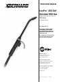
OPERATIONS MANUAL
IronPro™ 450 Self-
Shielded MIG Gun
Manufactured for Miller Electric Mfg. Co.
450 Amp
Part Number: 293039
Safety DepenDS On yOu!
DO NOT INSTALL, OPERATE OR REPAIR
THIS EQUIPMENT WITHOUT READING
THIS OPERATING MANUAL AND THE ARC
WELDING SAFETY PRECAUTIONS ON THE
INSIDE FRONT COVER.
Bernard® MIG Guns are designed and built
with safety in mind, but operators must
follow prescribed safety guidelines.

Protect yourself and others from injury – read, follow,
and save these important safety precautions and
operating instructions.
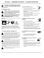
1-1 Symbol Usage
DANGER! – Indicates a hazardous situation which, if
not avoided, will result in death or serious injury. The
possible hazards are shown in the adjoining symbols
or explained in the text.
Indicates a hazardous situation which, if not avoided,
could result in death or serious injury. The possible
hazards are shown in the adjoining symbols or
explained in the text.
NOTICE–Indicatesstatementsnotrelatedtopersonalinjury.
– Indicatesspecialinstructions.
ThisgroupofsymbolsmeansWarning!WatchOut!
ELECTRICSHOCK,MOVINGPARTS,andHOTPARTShazards.
Consultsymbolsandrelatedinstructionsbelowfornecessary
actionstoavoidthehazards.
1-2 Arc Welding Hazards
Thesymbolsshownbelowareusedthroughoutthis
manualtocallattentiontoandidentifypossiblehazards.
Whenyouseethesymbol,watchout,andfollowthe
relatedinstructionstoavoidthehazard.Thesafetyinformation
givenbelowisonlyasummaryofthemorecompletesafety
informationfoundinsection1-4PrincipalSafetyStandardson
page3,andinweldingpowersourceOwner'sManual.Readand
followallSafetyStandards.
Onlyqualifiedpersonsshouldinstall,operate,maintain,
andrepairthisequipment.Aqualifiedpersonisdefined
asonewho,bypossessionofarecognizeddegree,
certificate,orprofessionalstanding,orwhobyextensive
knowledge,trainingandexperience,hassuccessfully
demonstratedabilitytosolveorresolveproblemsrelatingtothe
subjectmatter,thework,ortheprojectandhasreceivedsafety
trainingtorecognizeandavoidthehazardsinvolved.
Duringoperation,keepeverybody,especiallychildren,
away.
ELECTRIC SHOCK can kill.
lAlwaysweardryinsulatinggloves.
lInsulateyourselffromworkandground.
lDonottouchliveelectrodeorelectricalparts.
lReplaceworn,damaged,orcrackedgunsorcables.
lTurnoffweldingpowersourcebeforechangingcontacttipor
gunparts.
lKeepallcoversandhandlesecurelyinplace.
FUMES AND GASES can be hazardous.
lKeepyourheadoutofthefumes.
lVentilatearea,orusebreathingdevice.The
recommendedwaytodetermineadequate
ventilationistosampleforthecomposition
andquantityoffumesandgasestowhichpersonnelare
exposed.
lReadandunderstandtheSafetyDataSheets(SDSs)andthe
manufacturer’sinstructionsforadhesives,coatings,cleaners,
consumables,coolants,degreasers,fluxes,andmetals.
MOVING PARTS can injure.
lKeepawayfrommovingparts.
lKeepawayfrompinchpointssuchasdrive
rolls.
WELDING can cause fire or explosion.
lDonotweldnearflammablematerial.
lDonotweldoncontainersthathaveheld
combustibles,oronclosedcontainerssuchas
tanks,drums,orpipesunlesstheyare
properlypreparedaccordingtoAWSF4.1andAWSA6.0(see
SafetyStandards).
lWatchforfire;keepextinguishernearby.
lReadandunderstandtheSafetyDataSheets(SDSs)andthe
manufacturer’sinstructionsforadhesives,coatings,cleaners,
consumables,coolants,degreasers,fluxes,andmetals.
BUILDUP OF GAS can injure or kill.
lShutoffcompressedgassupplywhennotin
use.
lAlwaysventilateconfinedspacesoruseapprovedair-
suppliedrespirator.
ARC RAYS can burn eyes and skin.
Arcraysfromtheweldingprocessproduceintense
visibleandinvisible(ultravioletandinfrared)rays
thatcanburneyesandskin.Sparksflyofffromthe
weld.
1
SECTION 1 — SAFETY PRECAUTIONS — READ BEFORE USING

lWearanapprovedweldinghelmetfittedwithapropershade
offilterlensestoprotectyourfaceandeyesfromarcraysand
sparkswhenweldingorwatching(seeANSIZ49.1andZ87.1
listedinSafetyStandards).
lWearapprovedsafetyglasseswithsideshieldsunderyour
helmet.
lUseprotectivescreensorbarrierstoprotectothersfrom
flash,glareandsparks;warnothersnottowatchthearc.
lWearbodyprotectionmadefromleatherorflame-resistant
clothing(FRC).Bodyprotectionincludesoil-freeclothing
suchasleathergloves,heavyshirt,cufflesstrousers,high
shoes,andacap.
HOT PARTS can burn.
lAllowguntocoolbeforetouching.
lDonottouchhotmetal.
lProtecthotmetalfromcontactbyothers.
NOISE can damage hearing.
Noisefromsomeprocessesor
equipmentcandamagehearing.
lCheckfornoiselevellimits
exceedingthosespecifiedby
OSHA.
lUseapprovedearplugsorearmuffsifnoiselevelishigh.
lWarnothersnearbyaboutnoisehazard.
WELDING WIRE can injure.
lKeephandsandbodyawayfromguntipwhen
triggerispressed.
READ INSTRUCTIONS.
lReadandfollowalllabelsandtheOwner's
Manualcarefullybeforeinstalling,operating,
orservicingunit.Readthesafetyinformation
atthebeginningoftheManualandineachsection.
lUseonlygenuinereplacementpartsfromthemanufacturer.
lPerforminstallation,maintenance,andserviceaccordingto
theOwner'sManuals,industrystandards,andnational,state,
andlocalcodes.
2

1-3 California Proposition 65 Warnings
WARNING:Thisproductcanexposeyoutochemicals
includinglead,whichareknowntothestateofCaliforniato
causecancerandbirthdefectsorotherreproductiveharm.
Formoreinformation,gotowww.P65Warnings.ca.gov.
1-4 Principal Safety Standards
Safety in Welding, Cutting, and Allied Processes,AmericanWelding
SocietystandardANSIStandardZ49.1.Website:www.aws.org.
Safe Practice For Occupational And Educational Eye And Face
Protection,ANSIStandardZ87.1,fromAmericanNational
StandardsInstitute.Website:www.ansi.org.
Safe Practices for the Preparation of Containers and Piping for
Welding and Cutting,AmericanWeldingSocietyStandardAWS
F4.1.Website:www.aws.org.
National Electrical Code,NFPAStandard70fromNationalFire
ProtectionAssociation.Website:www.nfpa.org.
Safe Handling of Compressed Gases in Cylinders,CGAPamphletP-
1fromCompressedGasAssociation.Website:www.cganet.com.
Safety in Welding, Cutting, and Allied Processes,CSAStandard
W117.2fromCanadianStandardsAssociation.Website:
www.csagroup.org.
Standard for Fire Prevention During Welding, Cutting, and Other
Hot Work,NFPAStandard51BfromNationalFireProtection
Association.Website:www.nfpa.org.
OSHA,OccupationalSafetyandHealthStandardsforGeneral
Industry,Title29,CodeofFederalRegulations(CFR),Part
1910.177SubpartN,Part1910SubpartQ,andPart1926,Subpart
J. Website:www.osha.gov.
SR72022-01
1-5 EMF Information
Electriccurrentflowingthroughanyconductorcauseslocalized
electricandmagneticfields(EMF).Thecurrentfromarcwelding
(andalliedprocessesincludingspotwelding,gouging,plasmaarc
cutting,andinductionheatingoperations)createsanEMFfield
aroundtheweldingcircuit.EMFfieldsmayinterferewithsome
medicalimplants,e.g.Pacemakers.Protectivemeasuresfor
personswearingmedicalimplantshavetobetaken.Forexample,
restrictaccessforpassersbyorconductindividualriskassessment
forwelders.Allweldersshouldusethefollowingproceduresin
ordertominimizeexposuretoEMFfieldsfromtheweldingcircuit:
1. Keepcablesclosetogetherbytwistingortapingthem,or
usingacablecover.
2. Donotplaceyourbodybetweenweldingcables.Arrange
cablestoonesideandawayfromtheoperator.
3. Donotcoilordrapecablesaroundyourbody.
4. Keepheadandtrunkasfarawayfromtheequipmentinthe
weldingcircuitaspossible.
5. Connectworkclamptoworkpieceasclosetotheweldas
possible.
6. Donotworknextto,sitorleanontheweldingpowersource.
7. Donotweldwhilstcarryingtheweldingpowersourcewire
feeder.
About Implanted Medical Devices:
ImplantedMedicalDevicewearersshouldconsulttheirdoctorand
thedevicemanufacturerbeforeperformingorgoingneararc
welding,spotwelding,gouging,plasmaarccutting,orinduction
heatingoperations.Ifclearedbyyourdoctor,thenfollowingthe
aboveproceduresisrecommended.
3

Pour écarter les risques de blessure pour vous-même
et pour autrui — lire, appliquer et ranger en lieu sûr
ces consignes relatives aux précautions de sécurité et
au mode opératoire.
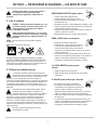
2-1 Symboles utilisés
DANGER! – Indique une situation dangereuse qui si
on l’évite pas peut donner la mort ou des blessures
graves. Les dangers possibles sont montrés par les
symboles joints ou sont expliqués dans le texte.
Indique une situation dangereuse qui si on l’évite pas
peutdonner la mort ou des blessures graves. Les
dangers possiblessont montrés par les symboles
joints ou sont expliquésdans le texte.
AVIS – Indique des déclarations pas en relation avec des blessures
personnelles.
–Indique des instructions spécifiques.
CegroupedesymbolesveutdireAvertissement!Attention!
DANGERDECHOCELECTRIQUE,PIECESENMOUVEMENT,et
PIECESCHAUDES.Reportez-vousauxsymbolesetauxdirectives
cidessousafindeconnaîtrelesmesuresàprendrepourévitertout
danger.
2-2 Dangers relatifs au soudage à l'arc
Lessymbolesdonnésci-aprèssontutilisésdanstoutle
ma-nuelpourattirerl’attentionsurlesdangers
possiblesetpourindiquerletypededangerdontils’agit.
Quandonvoitlesymbole,prendregardeetsuivrelesdirectives
corres-pondantespouréviterledanger.Lesconsignesdesécurité
présentéesci-aprèsnefontquerésumerl’informationcontenue
danslesNormesdesécuritéprincipales,etdansleGuide
d’utilisationdelasourcedecourantdesoudage.Lireetsuivre
touteslesNormesdesécurité.
L'installation,l'utilisation,l'entretienetlesréparationsne
doiventêtreconfiésqu'àdespersonnesqualifiées.Une
personnequalifiéeestdéfiniecommecellequi,parla
possessiond'undiplômereconnu,d'uncertificatoud'unstatut
professionnel,ouqui,paruneconnaissance,uneformationetune
expérienceapprofondies,adémontréavecsuccèssacapacitéà
résoudrelesproblèmesliésàlatâche,letravailouleprojeteta
reçuuneformationensécuritéafindereconnaîtreetd'éviterles
risquesinhérents.
Aucoursdel'utilisation,tenirtoutepersonneàl'écartet
plusparticulièrementlesenfants.
UN CHOC ÉLECTRIQUE peut tuer.
lPortertoujoursdesgantssecsetisolants.
lS’isolerdelapièceetdelaterre.
lNejamaistoucheruneélectrodeoudespiècesélectriques
soustension.
lRemplacerlespistoletsoucâblesdesoudagequisont
endommagés,usésoucraquelés.
lMettrelasoudeusehorstensionavantderemplacerunbec
contactoudespiècesdepistolet.
lS’assurerquetouslescouverclesetpoignéessont
fermementassujettis.
LES FUMÉES ET LES GAZ peuvent être
dangereux.
lGarderlatêtehorsdesfumées.
lAérerlazonedetravailouporterunappareil
respiratoire.Pourdéterminerlabonne
ventilation,ilestrecommandédeprocéderàunprélèvement
pourlacompositionetlaquantitédefuméesetdegaz
auxquelsestexposélepersonnel.
lLireetcomprendrelesfichesdedonnéesdesécuritéetles
instructionsdufabricantconcernantlesadhésifs,les
revêtements,lesnettoyants,lesconsommables,lesproduits
derefroidissement,lesdégraisseurs,lesfluxetlesmétaux.
Les PIÈCES MOBILES peuvent causer des
blessures.
lNepass’approcherdesorganesmobiles.
lNepass’approcherdespointsdecoincement
telsquedesrouleauxdecommande.
Le SOUDAGE peut provoquer un incendie ou
une explosion.
lNepassouderàproximitédematériaux
inflammables
lNepaseffectuerlesoudagesurdesconteneursferméstels
quedesréservoirs,tambours,ouconduites,àmoinsqu’ils
n’aientétépréparéscorrectementconformémentàAWSF4.1
etAWSA6.0(voirlesNormesdeSécurité).
lPrendregardeauxincendiesettoujoursavoirunextincteurà
proximité.
SECTION 2 — CONSIGNES DE SÉCURITÉ — LIRE AVANT UTILISATION
4

lLireetcomprendrelesfichesdedonnéesdesécuritéetles
instructionsdufabricantconcernantlesadhésifs,les
revêtements,lesnettoyants,lesconsommables,lesproduits
derefroidissement,lesdégraisseurs,lesfluxetlesmétaux.
L'ACCUMULATION DE GAZ risquent de
provoquer des blessures ou même la mort.
lFermerl’alimentationdugazcompriméencas
denonutilisation.
lVeillertoujoursàbienaérerlesespacesconfinésouseservir
d’unrespirateurd’adductiond’airhomologué.
LE RAYONNEMENT DE L'ARC peut brûler les
yeux et la peau.
Lerayonnementdel’arcduprocédédesoudage
génèredesrayonsvisiblesetinvisiblesintenses
(ultravioletsetinfrarouges)susceptiblesde
provoquerdesbrûluresdanslesyeuxetsurlapeau.Desétincelles
sontprojetéespendantlesoudage.
lPorteruncasquedesoudageapprouvémunideverres
filtrantsappropriépourprotégervisageetyeuxpendantle
soudage(voirANSIZ49.1etZ87.1énumérédanslesnormes
desécurité).
lPorterdeslunettesdesécuritéavecécranslatérauxmême
sousvotrecasque.
lAvoirrecoursàdesécransprotecteursouàdesrideauxpour
protégerlesautrescontrelesrayonnementsles
éblouissementsetlesétincelles;prévenirtoutepersonnesur
leslieuxdenepasregarderl’arc.
lPorteruneprotectioncorporelleencuiroudesvêtements
ignifu-ges(FRC).Laprotectionducorpscomportedes
vêtementssanshuile,commedesgantsdecuir,unechemise
solide,despanta-lonssansrevers,deschaussureshauteset
unecasquette.
LES PIÈCES CHAUDES peuvent provoquer
des brûlures.
lLaisserrefroidirlepistoletavantdeletoucher.
lNepastoucherd’objetsmétalliqueschauds.
lAbriterlesobjetsmétalliquescontretoutcontactparles
personnesàproximité.
Le BRUIT peut endommager l’ouie.
Lebruitdesprocessusetdeséquipementspeut
affecterl’ouïe.
lVérifiersilesniveauxdebruitexcèdentles
limitesspécifiéesparl’OSHA.
lUtiliserdesbouche-oreillesoudesserre-têteantibruit
approuvéssileniveaudebruitestélevé.
lAvertirlespersonnesàproximitéausujetdudangerinhérent
aubruit.
.
LES FILS DE SOUDAGE peuvent provoquer
des blessures.
lÉloignerlesmainsetlecorpsdelabusedu
pistoletaprèsavoirappuyésurlagâchette.
LIRE LES INSTRUCTIONS.
lLireetappliquerlesinstructionssurles
étiquettesetleModed’emploiavant
l’installation,l’utilisationoul’entretiende
l’appareil.Lirelesinformationsdesécuritéaudébutdu
manueletdanschaquesection.
lN’utiliserquelespiècesderemplacementprovenantdu
fabricant.
lEffectuerl’installation,l’entretienettouteinterventionselon
lesmanuelsd’utilisateurs,lesnormesnationales,provinciales
etdel’industrie,ainsiquelescodesmunicipaux.
5

2-3 Proposition californienne 65 avertissements
AVERTISSEMENT–Ceproduitpeutvousexposeràdes
produitschimiquestelsqueleplomb,reconnusparl’Étatde
Californiecommecancérigènesetsourcesdemalformationsou
d’autrestroublesdelareproduction
Pourplusd’informations,consulterwww.P65Warnings.ca.gov.
2-4 Principales normes de sécurité
Safety in Welding, Cutting, and Allied Processes,AmericanWelding
SocietystandardANSIStandardZ49.1.Website:www.aws.org.
Safe Practice For Occupational And Educational Eye And Face
Protection,ANSIStandardZ87.1,fromAmericanNational
StandardsInstitute.Website:www.ansi.org.
Safe Practices for the Preparation of Containers and Piping for
Welding and Cutting,AmericanWeldingSocietyStandardAWSF4.1
fromGlobalEngineeringDocuments.Website:www.aws.org.
National Electrical Code,NFPAStandard70fromNationalFire
ProtectionAssociation.Website:www.nfpa.org.
Safe Handling of Compressed Gases in Cylinders,CGAPamphletP-
1fromCompressedGasAssociation.Website:www.cganet.com.
Safety in Welding, Cutting, and Allied Processes,CSAStandard
W117.2fromCanadianStandardsAssociation.Website:
www.csagroup.org.
Standard for Fire Prevention During Welding, Cutting, and Other Hot
Work,NFPAStandard51BfromNationalFireProtection
Association.Website:www.nfpa.org.
OSHA,OccupationalSafetyandHealthStandardsforGeneral
Industry,Title29,CodeofFederalRegulations(CFR),Part1910.177
SubpartN,Part1910SubpartQ,andPart1926,SubpartJ.Website:
www.osha.gov.
SR7_fre2022-01
2-5 Informations relatives aux CEM
Lecourantélectriquequitraversetoutconducteurgénèredes
champsélectromagnétiques(CEM)àcertainsendroits.Lecourant
issud’unsoudageàl’arc(etdeprocédésconnexes,ycomprisle
soudageparpoints,legougeage,ledécoupageplasmaetles
opérationsdechauffageparinduction)créeunchamp
électromagnétique(CEM)autourducircuitdesoudage.Leschamps
électromagnétiquesproduitspeuventcauserinterférenceàcertains
implantsmédicaux,p.ex.lesstimulateurscardiaques.Desmesures
deprotectionpourlesporteursd’implantsmédicauxdoiventêtre
prises:parexemple,desrestrictionsd’accèspourlespassantsou
uneévaluationindividuelledesrisquespourlessoudeurs.Tousles
soudeursdoiventappliquerlesprocéduressuivantespour
minimiserl’expositionauxCEMprovenantducircuitdesoudage:
1. Rassemblerlescâblesenlestorsadantouenlesattachantavec
durubanadhésifouavecunehousse.
2. Nepasseteniraumilieudescâblesdesoudage.Disposerles
câblesd’uncôtéetàdistancedel’opérateur.
3. Nepascourberetnepasentourerlescâblesautourdevotre
corps.
4. Maintenirlatêteetletorseaussiloinquepossibledumatériel
ducircuitdesoudage.
5. Connecterlapincesurlapièceaussiprèsquepossibledela
soudure.
6. Nepastravailleràproximitéd’unesourcedesoudage,ni
s’asseoirousepencherdessus.
7. Nepassoudertoutenportantlasourcedesoudageoule
dévidoir.
En ce qui concerne les implants médicaux :
Lesporteursd’implantsdoiventd’abordconsulterleurmédecin
avantdes’approcherdesopérationsdesoudageàl’arc,desoudage
parpoints,degougeage,ducoupageplasmaoudechauffagepar
induction.Silemédecinapprouve,ilestrecommandédesuivreles
procéduresprécédentes.
6

Protéjase usted mismo y a otros contra lesiones —
lea, cumpla y conserve estas importantes
precauciones de seguridad e instrucciones de
utilización.
3-1 Uso de símbolos
PELIGRO! – Indica una situación peligrosa que, si no
se la evita, resultará en muerte o lesión grave. Los
peligros posibles se muestran en los símbolos
adjuntos o se explican en el texto.
Indica una situación peligrosa que, si no se la evita,
podríaresultar en muerte o lesión grave. Los peligros
posiblesse muestran en los símbolos adjuntos, o se
explican en eltexto.
AVISO – Indica precauciones no relacionadas a lesiones
personales.
–Indica instrucciones especiales.
Estegrupodesímbolossignifica¡Advertencia!,¡Cuidado!
CHOQUEODESCARGAELÉCTRICA,PIEZASQUESEMUEVEN,y
peligrosdePARTESCALIENTES.Consultelossímbolosylas
instruccionesrelacionadasqueaparecenacontinuaciónparaver
lasaccionesnecesariasparaevitarestospeligros.
3-2 Peligros en soldadura de arco
Lossímbolosmostradosabajoseusanentodoeste
manualparallamarlaatenciónaeidentificarlosposibles
peligros.Cuandoveaelsímbolo,presteatenciónysiga
lasinstruc-cionesrelacionadasparaevitarelpeligro.La
informacióndeseguridaddadaabajoessolamenteunresumende
lain-formaciónmáscompletadeseguridadqueseencuentraen
losestandaresdeseguridad,ylafuentedealimentaciónpa-ra
soldaduradelManualdelusuario.Leaysigatodaslasnormasde
seguridad.
Solamentepersonalcualificadodebeinstalar,utilizar,
manteneryrepararesteequipo.Ladefiniciónde
personalcualificadoescualquierpersonaque,debidoa
queposeeuntítulo,uncertificadoounaposiciónprofesional
reconocida,ograciasasugranconocimiento,capacitacióny
experiencia,hayademostradoconéxitolacapacidadpara
solucionaroresolverproblemasrelacionadosconeltrabajo,el
proyectooeltemaencuestión,ademásdehaberasistidoauna
capacitaciónenseguridadparareconoceryevitarlospeligrosque
implicaelproceso.
Durantesuoperaciónmantengalejosatodos,
especialmentealosniños.
UNA DESCARGA ELÉCTRICA puede matarlo.
lSiempreuseguantesaislantessecos.
lAísleseustedmismodeltrabajoylatierra.
lNotoqueelectrodoeléctricamentevivoopartes
eléctricamentevivas.
lReemplaceantorchasocablesdesgastados,dañadosorotos.
lRepareoreemplaceaislamientodelapistolaodelcableque
estédesgastado,dañadooagrietado.
lApaguelamáquinadesoldarantesdecambiarlostubosde
contactoopiezasdelaantorcha.
lMantengatodaslastapasyasabiensegurasensitio.
HUMO y GASES pueden ser peligrosos.
lMantengasucabezafueradelhumo.
lVentileellugarouseunaparatopararespirar.
Elmétodorecomendadoparadeterminarla
ventilaciónadecuadaestomarmuestrasdela
composiciónycantidaddehumosygasesalosqueestá
expuestoelpersonal.
lLeayentiendalasHojasdedatosdelmaterial(SDS)ylas
instruccionesdelfabricanterelacionadasconlosadhesivos,
metales,consumibles,recubrimientos,limpiadores,
refrigerantes,desengrasadores,fundentesymetales.
Las PIEZAS MÓVILES pueden provocar
lesiones.
lAléjesedetodaparteenmovimiento.
lAléjesedetodopuntoquepellizque,talcomorodillos
impulsados.
EL SOLDAR puede causar fuego o explosión.
lNosueldecercadematerialinflamable
lNosueldeenrecipientesquehancontenido
combustibles,nienrecipientescerradoscomo
tanques,tamboresotuberías,amenosque
esténpreparadoscorrectamentedeacuerdoconlanorma
AWSF4.1yAWSA6.0(vealasnormasdeseguridad).
lSiempremirequenohayafuegoymantengaunextinguidor
defuegocerca.
lLeayentiendalasHojasdedatosdelmaterial(SDS)ylas
instruccionesdelfabricanterelacionadasconlosadhesivos,
metales,consumibles,recubrimientos,limpiadores,
refrigerantes,desengrasadores,fundentesymetales.
7
SECTION 3 — PRECAUCIONES DE SEGURIDAD — LEA ANTES DE USAR

EL AMONTONAMIENTO DE GAS puede
enfermarle o matarle.
lCierreelsuministrodegascomprimido
cuandonolouse.
lSiempredéventilaciónaespacioscerradosouseun
respiradoraprobadoquereemplazaelaire.
LOS RAYOS DEL ARCO pueden quemar sus
ojos y piel.
Losrayosdelarcodeunprocesodesuelda
producenuncalorintensoyrayosultravioletas
fuertesquepuedenquemarlosojosylapiel.Las
chispasseescapandelasoldadura.
lUseunacaretaparasoldaraprobadaequipadaconunfiltrode
protecciónapropiadoparaprotegersucarayojosdelos
rayosdelarcoydelaschispasmientrasestésoldandoo
mirando.(véaselosestándaresdeseguridadANSIZ49.1y
Z87.1).
lUseanteojosdeseguridadaprobadosquetenganprotección
lateral.
lUsepantallasdeprotecciónobarrerasparaprotegeraotros
deldestello,reflejosychispas,alerteaotrosquenomirenel
arco.
lUseprotecciónparaelcuerpohechadecueroodeprendas
resis-tentesalasllamas(FRC).Entrelaprotecciónparael
cuerposein-cluyelaropasinaceite,comoguantesdecuero,
unacamisagruesa,pantalonessinvuelta,calzadoaltoyuna
gorra.
PARTES CALIENTES puedan causar
quemaduras severas.
lPermitaquelaantorchaseenfríeantesde
tocarla.
lNotoquemetalcaliente.
lProtejaaotrosdelcontactoconelmetalcaliente.
EL RUIDO puede trastornar su oído.
Ruidoprovenientedealgunosprocesosoequipo
puededañareloído.
lChequeeloslímitesdelniveldelruidosi
excedenaquellosespecificadosporOSHA.
lUsetapasparalosoídosocubiertasparalosoídossielnivel
delruidoesdemasiadoalto.
lAdviertaaotrosqueesténcercaacercadelpeligrodelruido.
El ALAMBRE de SOLDAR puede causarle
heridas.
lMantengalasmanosyelcuerpolejosdeltubo
decontactodelaantorchacuandosehaya
presionadoelgatillo.
LEER INSTRUCCIONES.
lLeaysigacuidadosamentelasinstrucciones
contenidasentodaslasetiquetasyenel
Manualdelusuarioantesdeinstalar,utilizaro
realizartareasdemantenimientoenlaunidad.Leala
informacióndeseguridadincluidaenlaprimerapartedel
manualyencadasección.
lUtiliceúnicamentepiezasdereemplazolegítimasdel
fabricante.
lLostrabajosdeinstalaciónymantenimientodebenser
ejecutadosdeacuerdoconlasinstruccionesdelmanualdel
usuario,lasnormasdelsectoryloscódigosnacionales,
estatalesylocales.
8

3-3 Advertencias de la Proposición 65 del estado de California
ADVERTENCIA:Esteproductopuedeexponerloaquímicos,
inclusoplomo,queelestadodeCaliforniaconocecomo
causantesdecáncer,defectosdenacimientouotrosdaños
reproductivos.
Paraobtenermásinformación,accedaa
www.P65Warnings.ca.gov.
3-4 Estándares principales de seguridad
Safety in Welding, Cutting, and Allied Processes,AmericanWelding
SocietystandardANSIStandardZ49.1.Website:www.aws.org.
Safe Practice For Occupational And Educational Eye And Face
Protection,ANSIStandardZ87.1,fromAmericanNational
StandardsInstitute.Website:www.ansi.org.
Safe Practices for the Preparation of Containers and Piping for
Welding and Cutting,AmericanWeldingSocietyStandardAWSF4.1
fromGlobalEngineeringDocuments.Website:www.aws.org.
National Electrical Code,NFPAStandard70fromNationalFire
ProtectionAssociation.Website:www.nfpa.org.
Safe Handling of Compressed Gases in Cylinders,CGAPamphletP-
1fromCompressedGasAssociation.Website:www.cganet.com.
Safety in Welding, Cutting, and Allied Processes,CSAStandard
W117.2fromCanadianStandardsAssociation.Website:
www.csagroup.org.
Standard for Fire Prevention During Welding, Cutting, and Other
Hot Work,NFPAStandard51BfromNationalFireProtection
Association.Website:www.nfpa.org.
OSHA,OccupationalSafetyandHealthStandardsforGeneral
Industry,Title29,CodeofFederalRegulations(CFR),Part
1910.177SubpartN,Part1910SubpartQ,andPart1926,Subpart
J. Website:www.osha.gov.
SR7_spa2022–01
3-5 Información sobre los campos electromagnéticos (EMF)
Lacorrientequefluyeatravésdeunconductorgeneracampos
eléctricosymagnéticos(EMF)localizados.Lacorrientedelarcode
soldadura(yotrastécnicasafinescomolasoldaduraporpuntos,el
ranurado,elcorteporplasmayelcalentamientoporinducción)
generauncampoEMFalrededordelcircuitodesoldadura.Los
camposEMFpuedeninterferirconalgunosdispositivosmédicos
implantadoscomo,porejemplo,losmarcapasos.Porlotanto,se
debentomarmedidasdeprotecciónparalaspersonasqueutilizan
estosimplantesmédicos.Porejemplo,apliquerestriccionesal
accesodepersonasquepasanporlascercaníasorealice
evaluacionesderiesgoindividualesparalossoldadores.Todoslos
soldadoresdebenseguirlosprocedimientosqueseindicana
continuaciónconelobjetodeminimizarlaexposiciónaloscampos
EMFgeneradosporelcircuitodesoldadura:
1. Mantengaloscablesjuntosretorciéndolosentresío
uniéndolosmediantecintasounacubiertaparacables.
2. Noubiquesucuerpoentreloscablesdesoldadura.Disponga
loscablesaunladoyapártelosdeloperario.
3. Noenrollenicuelgueloscablessobresucuerpo.
4. Mantengalacabezayeltroncotanapartadosdelequipodel
circuitodesoldaduracomoleseaposible.
5. Conectelapinzademasaenlapiezalomáscercaposibledela
soldadura.
6. Notrabajecercadelafuentedealimentaciónparasoldadura,
nisesienteorecuestesobreella.
7. Nosueldemientrastransportalafuentedealimentaciónoel
alimentadordealambre.
Acerca de los aparatos médicos implantados:
Laspersonasqueusenaparatosmédicoimplantadosdeben
consultarconsumédicoyelfabricantedelaparatoantesdellevara
cabooacercarseasoldaduradearco,soldaduradepunto,ranurar,
hacercorteporplasma,uoperacionesdecalentamientopor
inducción.Sisudoctorlopermite,entoncessigalos
procedimientosdearriba.
9

Introduction
Thank you for choosing Bernard. The product you have purchased has
been carefully assembled and factory tested prior to shipment. Should
you experience problems with installation or performance, please refer
to the “Troubleshooting Guide” in this manual.
Before installing, compare the equipment received against the invoice
to verify that the shipment is complete and undamaged. It is the
responsibility of the purchaser to file all claims of damage or loss that
may have occurred during transit with the carrier.
The manual contains general information on the operation of this
Bernard product. Before installing or operating any equipment, read
and understand the information and safety precautions presented
in this manual. Also, note the various data plates, labels, and tags
attached to the product.
While every precaution has been taken to assure the accuracy of this
manual, Bernard assumes no responsibility for errors or omissions.
Bernard assumes no liability for damages resulting from the use of
the information contained herein. Bernard shall have no liability to
the buyer for consequential damages or be liable to the in tort for
any negligent manufacture of the goods or for the omissions of any
warning therefrom.
Commercial Warranty
Product is warranted to be free from defects in material and
workmanship for 1 year after the sale by an authorized Buyer. Straight
handles, straight handle switches and straight rear strain reliefs are
covered by a lifetime warranty.
Bernard reserves the right to repair, replace or refund the purchase
price of non-conforming product. Product found not defective will be
returned to the Buyer after notification by Customer Service.
Bernard makes no other warranty of any kind, expressed or implied,
including, but not limited to the warranties of merchantability or fitness
for any purpose. Bernard shall not be liable under any circumstances
to Buyer, or to any person who shall purchase from Buyer, for
damages of any kind. Including, but not limited to any, direct, indirect
incidental or consequential damages or loss of production or loss of
profits resulting from any cause whatsoever, including, but not limited
to, any delay, act, error or omission of Bernard.
Genuine Bernard parts must be used for safety and performance
reasons or the warranty becomes invalid. Warranty shall not apply
if accident, abuse, or misuse damages a product, or if a product is
modified in any way except by authorized Bernard personnel.
Part I General Description
The IronPro™ 450 Self-Shielded MIG Gun is designed primarily for
processing mild steel electrode under FCAW (Flux Cored Arc
Welding).
The IronPro™ 450 Self-Shielded MIG Gun provides rapid neck
interchangeability, typically during production processes. Neck may
also be positioned on line within a 360 degree rotation. This position
allows for movements between standard horizontal welding,
overhead, and hard-to-reach side angles. The neck includes an
optional jump liner system that effectively reduces costs associated
with one-piece liner systems. Bernard is concerned about your
higher productivity.
The IronPro™ 450 Self-Shielded MIG Gun meets or exceeds NEMA
(National Electrical Manufacturer’s Association) EW3 requirements.
1. Your gun has been shipped with a specific feeder connector,
neck, and sized for electrode as per the part number
indicated on its package. Please inspect the received gun
against this part number for accuracy.
2. Turn off power prior to any installation.
3. Fully extend gun and cable. Press liner fully into power pin.
4. Safely expose approximately 2” (51 mm) of electrode
beyond feeder or adaptor block.
5. Power Pin
Connect the power pin of the direct plug gun by sliding the
electrode into the liner and the power fitting into the drive
housing of the feeder. Fully seat the unit in position and
tighten into place as designated in the manufacturer’s
instructions. On initial installations, a thin film of silicone
lubricant will aid installation and prevent o-ring damage.
Attach control lead wires to the appropriate plug, terminals,
or lead kit. Plug or wire into the control circuit of the feeder
as designated in manufacturer’s instructions.
6. Pull contact tip from neck tip adapter. An unobstructed electrode path has
now been established.
7. Safely feed electrode through the gun and approximately 1” (25 mm)
beyond head.
8. Slide contact tip over electrode into tip adapter on the neck by hand and
tighten with non-marring pliers. Torque to 30 in-lbs (3.5 Nm).
NOTE: AccuLock™ tip tool part # T-ALTOOL is recommended.
Welding current and duty cycle
shall not exceed published
specication of this product. If such
conditions exist, product life and
performance will be reduced.
Part II Installation
10

1. Tip insulation could be unthreaded slightly to extend the life
the of part.
Cable:
1. Periodically check torques of neck and end fittings. Loose
fittings can cause overheating and premature failure of the
gun.
2. Sharp bends and loops in the cable should be avoided. Often
the best solution is to suspend the wire feeder from a boom
or trolley, thus eliminating a large number of bends and
keeping the cable clear of hot weldments.
3. Do not immerse liner into solvents for cleaning; the liner may
be periodically blown out with compressed air.
4. Avoid rough surfaces and sharp edges that can cause tears
and nicks in cable jacket which can cause premature failure.
5. Periodically check all cables and ground connections.
6. Use anti-seize on all threaded connections.
Part III Helpful Operating Tips
Tip Insulation:
Feeder:
1. Check drive rolls for wear; be sure drive rolls and guide
tubes are clean and free of debris. Do not overtighten drive rolls;
set as per manufacturer’s specifications.
2. Use clean, non-corroded electrode.
3. When installing or replacing electrode, you may: remove
burrs from end of electrode, remove head/gas diffuser and
contact tip, and/or straighten the first few inches of elec-
trode.
End User Stocking Recommendations:
Contact Tips .............................. 30 for every 1 gun in service
Triggers ..................................... 1 for every 10 guns in service
Necks ........................................ 1 for every 10 guns in service
Handle Kits ................................ 1 for every 20 guns in service
Strain Relief Kits ....................... 1 for every 20 guns in service
Power Pin Kits .......................... Order as Necessary
These stocking recommendations are only initial guidelines based on
an 80 hour work period. You should work closely with your distributor
to tailor a stocking program that suits your specific needs. Results will
vary.
11

Disconnect gun from equipment, allow to cool, and remove electrode from liner before servicing.
Part IV Maintenance and Repair
See page 17 for parts list
12
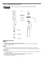
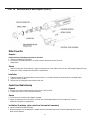
CONVENTIONAL CABLE LINER
REMOVAL
1. Remove neck, heat shield and heat shield nut and lay cable straight.
2. Remove rear guide cap, then using a 10 mm wrench, turn liner counter-clockwise until it is free from the power pin.
3. Remove liner from gun assembly.
SERVICE
1. Inspect for excessive wear and debris on the inside diameter. Do not dip liner in solvents for cleaning. Liner may be
periodically blown out with shop air. Replace with new liner when excessive wear or debris produces poor electrode feed.
INSTALLATION
1. With cable laying straight, insert new liner into power pin and feed through gun using short strokes to prevent kinking. Twist
liner clockwise if necessary.
2. Use a 10 mm wrench to turn liner lock clockwise to tighten into power pin, then replace guide cap.
3. Trim liner flush with front adapter block (as shown in the above figure).
4. Then reassemble neck and heat shield.
WARNING

Part IV Maintenance and Repair (cont.)
13
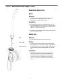
2. Before installing, inspect neck and adapter block of the front
gun handle for debris, clean if necessary. Then, take the tapered
end of the neck and insert into adapter block, making sure the
cable liner is inserted into jump liner.
3. Install neck in reverse order of removal, adjust neck by twisting
into place, torque to 38in-lbs.
Jump Liner
1.Remove used jump liner from the back end of neck.
Inspect for excessive wear and debris on the inside diameter.
Do not dip jump liner in solvents for cleaning. Jump liners may
be periodically blown out with shop air. Replace with new jump
liner when excessive wear or debris produces poor electrode
feed.
Insert jump liner making sure the liner stop is fully seated
at the back of the neck. For new jump liner replacement,
measure the jump liner from rear of liner lock to tip of the
liner. For 12" long necks (1370270) measure and trim to
10-7/8". For 7" short necks (1370271) measure and trim to
5-7/8".
Neck and Jump Liner
Neck
Removal
1. Remove neck from adapter block on the front gun handle
by grasping lock nut and rotate counter-clockwise.
Rotation will free neck from adapter block.
Installation
Service
Removal
Installation
2.
3.

Part IV Maintenance and Repair (cont.)
14
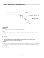
1. Tip insulation can be removed by turning in a counter-clockwise direction.
clockwise direction.
Tip Insulation
Removal
Service
2. Inspect for cracks and degradation of insulation. Replace the insulation when loose, worn, or exposing the tip of the neck.
Installation
3. Replace threaded fit nozzle by threading in a clockwise direction. Tip Insulation should allow about 1/4" of the contact tip exposed.
Contact Tip
Removal
1. Cut electrode and remove all burrs. Remove threaded tip insulation by turning in a counter-clockwise direction.
Remove contact tip by turning in a counter-clockwise direction.
Installation
Replacement is accomplished by cutting electrode and removing all burrs. Slide contact tip over electrode into tip adapter on the
neck by hand and tighten with non-marring pliers. Torque to 30 in-lbs (3.5 Nm). NOTE: AccuLock tip tool part # T-ALTOOL is
recommended.
Reinstall tip insulation.
2.
3.

15
Part IV Maintenance and Repair (cont.)
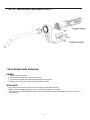
T Series Straight Handle (Switch Only)
REMOVAL
1. Remove neck and heat shield.
2. Remove both housing screws with an 8 mm nut driver.
3. Ease switch out of trigger housing with needle nose pliers to grip switch.
4. Remove switch from switch lead connectors with needle nose pliers.
INSTALLATION
5. Push switch lead connectors firmly onto new switch terminals with needle nose pliers.
6. Depress switch into trigger housing, then nest on handle (switch leads must lay parallel).
7. Align housing holes with threaded holes in body and insert mounting screws first before tightening with 8 mm nut driver to
even alignment.

16
Part IV Maintenance and Repair (cont.)
Miller Power Pin
Removal
Remove the liner by following steps listed for cable liner:
1. Remove pin/adapter block insulation.
2. Use wrenches and rotate power pin in a counter-clockwise direction to remove it from the
adapter block.
Service
Control Lead Cable Housing
Removal
1. Remove screw covers and both housing screws with an 8 mm nut driver.
2. (If replacing cut wires at back of the butt connectors).
Service
Test lead wires for continuity when trigger is engaged.
Inspect all components for cracks, debris, excessive wear, and breakage. Replace with new components if safety or
performance of product is compromised.
Installation (If replacing, splice control lead into new butt connectors)
Lay butt connectors parallel with handle.
Align housing holes with threaded holes in adapter block and insert mounting screws first before tightening with 8 mm nut
driver to even alignment.
3.
4.
6.
7.
Lubricate o-rings with silicone lubricant. Inspect all components for cracks, debris, excessive wear, and breakage. Replace with new
components if safety or performance of product is compromised.
3.
Installation
Thread new power pin into adaptor block and use wrenches in a clockwise direction to thread power pin into adaptor block.
Torque to 18 ft-lbs (24 Nm).
Reinstall liner by following the steps listed for cable liner.
4.
5.
6.

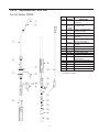
Part V Replacement Parts List
Gun Part Number: 293039
ITEM
PART
NUMBER DESCRIPTION
1NS-AFLX Nozzle Assembly, Gasless -
AccuLock™
2T-A072CH*AccuLock Contact Tip wire
size 0.072”-3/32”
31370270 Gasless, 12"-30 Deg Q-Neck
Assembly, AccuLock
4QJL-L7
52030037 Universal Q-Neck Adaptor
Shield Nut
61760013 Universal Q-Neck Adaptor -
One Piece Heat Shield**
71680085U Universal Q-Neck Adaptor
Assembly
8410S Short T-Series Handle
9411-2 Switch Housing Assembly
10 411-3M Screw M5x12mm Hex Head
11 414-400 Universal Adapter Detail
12 1620004
13
Hex Head Screw Cover
1810053 Rear Pod, Low Profile, W/2
Butt Connectors
142200137 Miller® Power Pin Assembly
15 L7A-15 Liner Assembly
16 214-332 Guide Cap - Miller
17 414-400-20 Power Pin Insulator
18 2950001 Cap Plug
17
Gasless 3/32" Jump Liner
T-A078CH*
T-A094CH
*Sold Separately
** Included, not installed

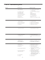
Part VI Troubleshooting Guide
PROBLEM POSSIBLE CAUSE CORRECTIVE ACTION
1. Electrode does not feed. 1. Feeder relay.
2. Broken control lead.
3. Poor adaptor connection.
4. Worn or broken switch.
5. Improper drive roll size.
6. Drive roll tension misadjusted.
7. Burn back to contact tip.
8. Wrong size liner.
9. Buildup inside of liner.
1. Consult feeder manufacturer.
2. a. Test & connect spare control lead.
b. Install new cable.
3. Test & replace leads and/or contact pins.
4. Replace.
5. Replace with proper size.
6. Adjust tension at feeder.
7. See ‘contact tip burn back’.
8. Replace with correct size.
9. Replace liner, check condition of electrode.
2. Contact tip burn back. 1. Improper voltage and/or wire feed speed.
2. Erratic wire feeding.
3. Improper contact tip stickout.
4. Improper electrode stickout.
5. Faulty ground.
1. Set parameters.
2. See ‘erratic wire feeding’.
3. Adjust nozzle/contact tip relationship.
4. Adjust gun to base metal relationship.
5. Repair all cables & connections.
3. Contact Tip disengages from head. 1. Improper contact tip installation.
2. Extreme heat or duty cycle.
1. Install as per Maintenance & Repair Section.
2. Replace with heavy duty consumables.
5. Erratic arc. 1. Worn contact tip.
2. Buildup inside of liner.
3. Wrong contact tip size.
4. Not enough bend in neck.
1. Replace.
2. Replace liner, check condition of electrode.
3. Replace with correct size contact tip.
4. Replace with 30º or optional short 60º neck.
4. Short contact tip life. 1. Contact tip size.
2. Electrode eroding contact tip.
3. Exceeding duty cycle.
1. Replace with proper size.
2. Inspect and/or change drive rolls.
3. Replace with properly rated Bernard® MIG
Gun.
6. Erratic wire feeding. 1. Buildup inside of liner.
2. Wrong size liner.
3. Improper drive roll size.
4. Worn drive roll.
5. Improper guide tube relationship.
6. Improper wire guide diameter.
7. Gaps at liner junctions.
8. Feeder malfunction.
9. Contact tip.
1. Replace liner, check condition of electrode.
2. Replace with new liner of proper size.
3. Replace with proper size drive roll.
4 a. Replace with new drive roll.
b. Stone edge of groove on drive roll.
5 a. Adjust/replace guide as close to drive rolls
as possible.
b. Eliminate all gaps in electrode path.
6. Replace with proper guide diameter.
7 a. Replace with new liner trimming as per
‘Maintenance & Repair’ (Section IV).
b. Replace guide tube/liner, trim as close to
mating component as possible.
8. Consult feeder manufacturer.
9. Inspect and replace.
17
18

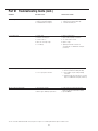
Part VI Troubleshooting Guide (cont.)
*In some cases with aluminum and mild steels, it may be necessary to use a contact tip with either a larger or smaller bore size.
7. Extreme spatter. 1. Improper machine parameters.
2. Improper contact tip installation.
3. Contaminated wire or work piece.
1. Adjust parameters.
2. Adjust nozzle/contact tip relationship.
3. Clean wire and work piece.
8. Porosity in weld. 1. Insulator worn.
2. Extreme heat or duty cycle.
3. Control circuit loss.
4. Worn, cut or missing o-rings.
5. Loose fittings.
1. Replace nozzle/insulator.
2. Replace with heavy duty consumables.
3. See ‘electrode does not feed’.
4. Replace o-rings.
5.
9. Gun running hot. 1. Exceeding duty cycle.
2. Loose or poor power connection.
1. a. Replace with properly rated Bernard MIG gun.
b. Decrease parameters to within gun rating.
2. a. Clean, tighten or replace cable grounding
connection.
b. Tighten gun and cable connections to specified
torque. See ‘Maintenance & Repair’ (Section IV).
10. Liner is discolored full length. 1. Short circuit to electrode.
2. Broken copper stranding in power cable.
1. Isolate electrode reel from feeder and drive
block. Consult feeder manufacturers manual.
2. Replace MIG Gun.
PROBLEM POSSIBLE CAUSE CORRECTIVE ACTION
18
19
Tighten gun and cable connections to
specified torque. See ‘Maintenance & Repair’
(Section IV).

Notes
© 2023 Bernard Printed in U.S.A. OM-IP 1.0
-
 1
1
-
 2
2
-
 3
3
-
 4
4
-
 5
5
-
 6
6
-
 7
7
-
 8
8
-
 9
9
-
 10
10
-
 11
11
-
 12
12
-
 13
13
-
 14
14
-
 15
15
-
 16
16
-
 17
17
-
 18
18
-
 19
19
-
 20
20
-
 21
21


Tregaskiss 293039 Iron Pro 450 Self Shielded MIG Gun Manual de usuario
- Categoría
- Sistema de soldadura
- Tipo
- Manual de usuario
en otros idiomas
Artículos relacionados

Otros documentos
-
Bernard 600 Amp Manual de usuario
-
Miller BLUE STAR 185 DX El manual del propietario
-
-
HobartWelders HANDLER 125 EZ AND H-9B GUN El manual del propietario
-
-
-