Samoa 363112 Instructions Manual
- Categoría
- Rociador de pintura
- Tipo
- Instructions Manual

2019_07_22-10:00
1
R. 07/19 836 829
SAMOA Industrial, S.A. · Pol. Ind. Porceyo, I-14 · Camino del Fontán, 831 · 33392 - Gijón - Spain · Tel.: +34 985 381 488 · www.samoaindustrial.com
Part No. / Cód. / Réf. / Art. Nr. /
Деталь №:
363 100
OIL CONTROL HANDLE 2
PISTOLA DE ACEITE 7
POIGNEE DE DISTRIBUTION 12
COMANDO DE ÓLEO PARA ÓLEO LUBRIFICANTE 17
РУКОЯТКА ДЛЯ РЕГУЛИРОВАНИЯ ПОТОКА МАСЛА 22
EN
ES
FR
PT
RU
Parts and technical service guide
Guía de servicio técnico y recambio
Guide d’instructions et pièces de rechange
Bedienungsanleitung und Teileliste
Руководство по техническому обслуживанию и деталям

2019_07_22-10:00
2836 829 R. 07/19
SAMOA Industrial, S.A. · Pol. Ind. Porceyo, I-14 · Camino del Fontán, 831 · 33392 - Gijón - Spain · Tel.: +34 985 381 488 · www.samoaindustrial.com
EN
• This unit is intended for professional use. Read all the
instructions in this manual prior to use.
• Only use the unit for the purposes for which it is intended.
• Do not alter or modify the unit.
• Do not exceed the maximum unit working pressure.
See page 6 of the technical specifications.
• Use the unit with fluids and solutions which are
compatible with the moist parts of the unit. See the
relevant section of the technical specifications.
• Observe the manufacturer’s safety warnings for the
fluids used.
WARNING: Release all pressure within the
system prior to performing any maintenance or
disassembly operation.
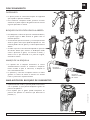
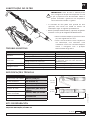
• The control valve is designed to dispense a variety of
fluid lubricants and antifreeze fluid.
• The control handle allows a progressive openning valve
for better control of oil delivery. The valve can be locked
in open position by means of the trigger button.
• The gun includes protection to prevent accidental
opening. Refer to the operation section for details of
operation.
• All guns include 1/2” BSP threaded swivel, a swivel
cover and nozzle extension outlet with automatic or
quarter turn opening non-drip tip.
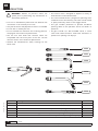
INTRODUCTION
!
369224
369226
369228
369230
369232
369234
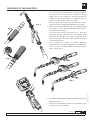
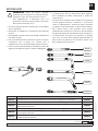
Part No. Description Extension
363112 Oil control handle with flexible outlet and automatic non-drip tip. 369224
363113 Oil control handle with flexible formable outlet and automatic non-drip tip. 369226
363114 Oil control handle with 90º flexible outlet and quarter turn opening non-drip tip. 369228
363115 Oil control handle with 90º flexible outlet and automatic non-drip tip. 369230
363116 Oil control handle with 60º rigid outlet and quarter turn opening non-drip tip. 369232
363117 Oil control handle with flexible formable outlet and quarter turn opening non-drip tip. 369234

2019_07_22-10:00
3
R. 07/19 836 829
SAMOA Industrial, S.A. · Pol. Ind. Porceyo, I-14 · Camino del Fontán, 831 · 33392 - Gijón - Spain · Tel.: +34 985 381 488 · www.samoaindustrial.com
EN
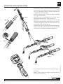
MOUNTING AND INSTALLATION
Fig. 1
Fig. 2
Fig. 3
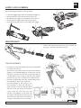
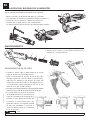
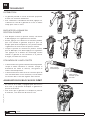
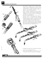
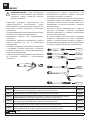
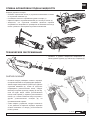
• To ensure the sealing, mount the extension outlet using
the provided o-ring, taking care that the position of the
o-ring in the flange housing is correct. Lubricate the
o-ring before mounting (fig. 4).
• Attach the swivel cover to the house before installing
the oil gun in the system.
• The swivel cover is compatible with 1/2" hoses, either
with male fixed terminal or swivel nut (fig. 1).
• Depending on the type of terminal hose may be
necessary to open the end of the swivel cover to allow
its passage through the hose. The swivel cover has a slot
at its end for easy opening (fig. 2).
• To connect the gun to the network, keep fixed the gun
body and the end of the hose while rotate the free end
of the swivel to achieve the desired torque (fig. 3).
• A flow meter can be attached to the gun by means of
the flange.
• Employ a 24 x 2 mm size o-ring (1) and two M5 x 14
screws (2) for mounting.
1
2
Fig. 4

2019_07_22-10:00
4836 829 R. 07/19
SAMOA Industrial, S.A. · Pol. Ind. Porceyo, I-14 · Camino del Fontán, 831 · 33392 - Gijón - Spain · Tel.: +34 985 381 488 · www.samoaindustrial.com
EN
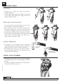
DISPENSED
OPERATING MODE
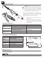
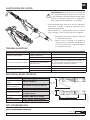
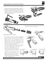
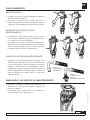
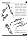
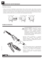
• The gun has a safety lock system that prevents
accidental opening.
• To begin dispensing fluid, push the button on the top
of the trigger while pulling the trigger toward gun
handle to open the valve.
OPEN VALVE LOCK POSITION
• To lock the valve in fully open position, first you must
pull the trigger to its maximum opening.
• Then press the button and hold it pressed while
releasing the trigger until it is locked. At this point you
can release the trigger and the valve will remain open.
• When the gun is locked in open valve position to unlock
it you must press the trigger again without pressing the
button. Then release the trigger and it backs to its
original position, closing the valve.
NOZZLE OPERATION
• The opening of the automatic nozzle is performed
automatically when the fluid begins to flow. When fluid
dispensing ends, the nozzle is closed automatically.
• The opening and closing of the manual nozzle is
performed turning quarter turn the end clockwise and
counterclockwise respectively.
AUTOMATIC
NOZZLE
QUARTER TURN
MANUAL NOZZLE
SUPPLY LOCK OVERRIDE
• Depending on the model, the oil gun can be supplied
as standard with a pin (1) to lock the trigger in the open
position.
• To avoid the trigger can be locked in the open position
is necessary to remove the pin (1).

2019_07_22-10:00
5
R. 07/19 836 829
SAMOA Industrial, S.A. · Pol. Ind. Porceyo, I-14 · Camino del Fontán, 831 · 33392 - Gijón - Spain · Tel.: +34 985 381 488 · www.samoaindustrial.com
EN
SUPPLY LOCK OVERRIDE
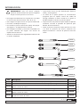
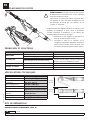
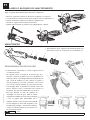
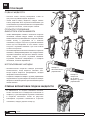
Use the following procedure to remove the pin:
• Loosen the trigger fixing screws (2) and pull the trigger (3).
• Using a hammer and a punch remove the pin (1).
• Reassemble the trigger (3) and tighten the screws (2).
• Check that the trigger opens and closes properly.
• Over-tightening the screws (2) may block the trigger. 12
3
2
1
2
2
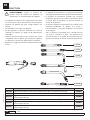
MAINTENANCE
• Loosen and remove the swivel (1), then remove the
spring (2), the valve (3) and the rod (4).
1
4
3
2
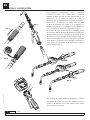
CAM DISSASEMBLY
• Proceed first to the disassembly of the valve as described
in the previous section.
• Then remove the screws of the cam (4) and remove the
trigger (5). To avoid damaging the o-rings, push out the
cam (6) on one side until only the o-ring of that side (7)
is visible. Remove the o-ring (7) and then fully remove
the cam with the other o-ring (8) on the opposite side.
• To mount, proceed the other way around taking care in
the assembly of the o-rings of the cam.
• To avoid damage to the o-rings in the
cam assembly, it must be mounted a
single ring (8) on cam (6) and then place
the cam in the gun by the end without
o-ring. Slide the cam until the end
without o-ring appears on the other side
of the gun, with special care that only the
groove of the o-ring stands. Introduce the
o-ring (7) and place the shaft in position.

2019_07_22-10:00
6836 829 R. 07/19
SAMOA Industrial, S.A. · Pol. Ind. Porceyo, I-14 · Camino del Fontán, 831 · 33392 - Gijón - Spain · Tel.: +34 985 381 488 · www.samoaindustrial.com
EN
FILTER REPLACEMENT
WARNING: Release all pressure within the system
and disconnect the air supply to the pump prior to
performing strainer replacement. Discharge
pressure operating the gun into an appropriate
container and open any bleeder-type air valves and
fluid drain valves in the system if necessary.
!
TROUBLE-SHOOTING
TECHNICAL SPECIFICATIONS
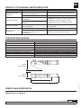
• The gun can be provided with a strainer (optional). To
inspect strainer or make replacement read the following
procedure. Remove the cover (1) (optional) of the
swivel and loosen the nut (2) of the hose.
1
2
• Remove the o-ring (3) fixing the filter (4)
and then filter.
• Check the filter and cleaning it or replacing as
necessary. Place again the filter with the
o-ring and install the hose with the swivel
cover (optional).
4
3
Maximum flow rate 40 l/min (4.5 gpm)
Maximum working
pressure 100 bar (1450 psi)
Operating
temperature range -10 ºC to 70 ºC (14 ºF to 158 ºF)
Burst pressure 400 bar (5800 psi)
Fluid inlet 1/2" BSP
Fluid outlet 1/2" BSP y brida con alojamiento
para junta tórica
Wetted parts Aluminio, NBR, acero cincado
Fluid compatibility Aceite, glicol y anticongelante
Weight 500 g (1.1 lb)
110 mm
(4.3 in)
55 mm
(2.1 in)
180 mm (7.1 in)
250 mm (9.8 in)
PROBLEM CAUSE SOLUTION
Slow flow. Strainer clogged, if it is installed (optional). Clean or replace strainer.
Pump pressure is low. Increase pump air pressure.
Valve leaks. Valve seal worn or damaged. Disassemble the valve for inspection. If it is
not damaged, clean seat valve. Otherwise,
replace the valve.
Foreign material on valve seal.
Leakage at cam. O-ring worn or damaged. Replace o-ring according to instructions.
Leakage at swivel. The swivel is loose. Tighten swivel assembly.
Swivel o-ring worn or damaged. Replace o-ring.
SPARE PARTS SEE PAGE 28.
REPARATION KITS

7
R. 07/19 836 829
SAMOA Industrial, S.A. · Pol. Ind. Porceyo, I-14 · Camino del Fontán, 831 · 33392 - Gijón - Spain · Tel.: +34 985 381 488 · www.samoaindustrial.com
ES
2019_07_22-10:00
• Este equipo está destinado a uso profesional. Lea todas
las instrucciones de este manual antes de su uso.
• Use el equipo sólo para los fines a los que está destinado.
• No altere o modifique el equipo.
• No exceda la presión máxima de trabajo del equipo.
Vea página 11 de especificaciones técnicas.
• Use el equipo con fluidos y soluciones compatibles con
las partes húmedas del equipo. Vea sección de
especificaciones técnicas.
• Atienda las advertencias de seguridad del fabricante de
los fluidos empleados.
ADVERTENCIA: Antes de realizar cualquier
operación de desmontaje de la pistola asegúrese
de que no existe presión en el circuito.
• La pistola de control ha sido diseñada para dispensar
aceite y anticongelante.
• La válvula de la pistola permite un accionamiento
progresivo para un óptimo control del caudal de
entrega. Mediante el botón situado en el gatillo es
posible bloquear la válvula en posición abierta.
• La pistola tiene una protección para impedir la apertura
accidental. Consulte el apartado de operación para
detalles de funcionamiento.
• Todas las pistolas incorporan rótula giratoria con rosca
1/2” BSP, un protector de rótula y extensión con
boquilla automática o manual de apertura cuarto de
vuelta.
INTRODUCCIÓN
!
369224
369226
369228
369230
369232
369234
Cód. Descripción Extensión
363112 Pistola de control de aceite con extensión flexible y boquilla antigoteo automática. 369224
363113 Pistola de control de aceite con extensión flexible conformable y boquilla antigoteo automática. 369226
363114 Pistola de control de aceite con extensión flexible a 90º y boquilla antigoteo manual de
apertura cuarto de vuelta. 369228
363115 Pistola de control de aceite con extensión flexible a 90º y boquilla antigoteo automática. 369230
363116 Pistola de control de aceite con extensión rígida a 60º y boquilla antigoteo manual de
apertura cuarto de vuelta. 369232
363117 Pistola de control de aceite con extensión flexible conformable y boquilla antigoteo manual
de apertura cuarto de vuelta. 369234

2019_07_22-10:00
8836 829 R. 07/19
SAMOA Industrial, S.A. · Pol. Ind. Porceyo, I-14 · Camino del Fontán, 831 · 33392 - Gijón - Spain · Tel.: +34 985 381 488 · www.samoaindustrial.com
ES
MONTAJE E INSTALACIÓN
Fig. 1
Fig. 2
Fig. 3
• Para asegurar la estanqueidad, monte la extensión
utilizando la junta tórica suministrada y teniendo
especial cuidado de que la junta permanezca en su
alojamiento en la salida del cuerpo de pistola o
contador (fig. 4). Lubrique la tórica previo al montaje.
• Previamente a la conexión a la red de la pistola, debe
acoplar el protector de rótula a la manguera. El
protector de rótula es compatible con mangueras de
1/2” con terminal macho fijo o tuerca loca (fig. 1).
• En función del tipo de terminal de la manguera puede
ser necesario abrir el extremo del protector para permitir
su deslizamiento por la manguera. El protector posee
una ranura en su extremo que facilita su apertura (fig. 2).
• Para conectar la pistola a la red, mantenga fijo el cuerpo
de la pistola y el extremo de la manguera mientras se
hace girar el extremo libre de la rótula hasta lograr el
apriete deseado (fig. 3).
• Un medidor de caudal puede ser acoplado a la pistola
por medio de la brida de la pistola. Emplee una junta
tórica (1) de tamaño 24 x 2 mm y dos tornillos (2) de
M5 x 14 para el montaje.
1
2
Fig. 4

9
R. 07/19 836 829
SAMOA Industrial, S.A. · Pol. Ind. Porceyo, I-14 · Camino del Fontán, 831 · 33392 - Gijón - Spain · Tel.: +34 985 381 488 · www.samoaindustrial.com
ES
2019_07_22-10:00
DISPENSADO
FUNCIONAMIENTO
• La pistola posee un sistema de bloqueo de seguridad
que impide la apertura accidental.
• Para comenzar a dispensar fluido, presione el botón
situado en la parte superior del gatillo mientras acciona
el gatillo para abrir la válvula.
BLOQUEO EN POSICIÓN VÁLVULA ABIERTA
• Para bloquear la válvula en posición totalmente abierta,
en primer lugar se debe accionar el gatillo hasta su
máxima apertura.
• A continuación presione el botón y con éste presionado
suelte el gatillo hasta que quede bloqueado. En este
instante puede soltar el gatillo y la válvula permanecerá
abierta.
• Cuando la pistola se encuentra bloqueada en posición
de válvula abierta para realizar el desbloqueo debe
volver a presionar el gatillo, sin accionar el botón, y
soltarlo con lo que retrocede a su posición original,
cerrando la válvula.
MANEJO DE LA BOQUILLA
• La apertura de la boquilla automática se realiza
automáticamente cuando se comienza a dispensar
fluido. Cuando se para el suministro, la boquilla se
cierra automáticamente.
• La apertura y cierre de la boquilla manual se realiza
girando un cuarto de vuelta el extremo en sentido
horario y antihorario respectivamente.
BOQUILLA
AUTOMÁTICA
BOQUILLA
MANUAL CUARTO
DE VUELTA
ANULACIÓN DEL BLOQUEO DE SUMINISTRO
• Dependiendo del modelo, la pistola puede suministrarse
con un pasador (1) que permite bloquear el gatillo en
posición de apertura.
• Para impedir que el gatillo pueda bloquearse en
posición de apertura es necesario que desmonte el
pasador (1).

2019_07_22-10:00
10 836 829 R. 07/19
SAMOA Industrial, S.A. · Pol. Ind. Porceyo, I-14 · Camino del Fontán, 831 · 33392 - Gijón - Spain · Tel.: +34 985 381 488 · www.samoaindustrial.com
ES
ANULACIÓN DEL BLOQUEO DE SUMINISTRO
Siga el siguiente procedimiento para desmontar el pasador:
• Afloje los tornillos (2) de sujeción del gatillo (3) y extraerlo.
• Con ayuda de un martillo y un botador extraiga el pasador (1).
• Monte de nuevo el gatillo (3) y apriete los tornillos (2).
• Verifique que el gatillo abre y cierre correctamente.
Un apriete excesivo de los tornillos (2) podría bloquear el gatillo. 12
3
2
1
2
2
MANTENIMIENTO
• Afloje y retire la rótula (1) para extraer el muelle (2), la
válvula (3) y el empujador (4).
1
4
3
2
DESMONTAJE DEL EJE DE GIRO
• Proceda en primer lugar al desmontaje de la válvula
según lo descrito en el apartado anterior.
• Quite a continuación los tornillos del eje de giro (4) y
extraiga el gatillo (5). Para no dañar las juntas tóricas,
saque por un extremo el eje de giro (6) hasta que
asome sólo la junta de ese lado (7). Extraiga la tórica (7)
y a continuación saque totalmente el eje con la otra
junta tórica (8) por el lado contrario.
• Para realizar el montaje proceda a la inversa poniendo especial
atención en el montaje de las juntas tóricas del eje de giro.
• Para evitar dañar las juntas en el montaje
del eje debe montar una sola tórica (8) en
el eje (6) e introducirlo en la pistola por el
extremo sin junta. Deslice el eje hasta que
el extremo sin junta asome por el otro
lateral de la pistola, con especial cuidado
de que sólo sobresalga la cajera de la
junta. Introduzca la junta (7) y coloque el
eje en su posición.

11
R. 07/19 836 829
SAMOA Industrial, S.A. · Pol. Ind. Porceyo, I-14 · Camino del Fontán, 831 · 33392 - Gijón - Spain · Tel.: +34 985 381 488 · www.samoaindustrial.com
ES
2019_07_22-10:00
SUSTITUCIÓN DEL FILTRO
ADVERTENCIA: Antes de realizar la sustitución del
filtro asegúrese de que no hay presión en el circuito
y que la bomba se encuentra desconectada. Libere
presión accionando la pistola en un recipiente y
actúe sobre válvulas de drenaje si es necesario.
!
TROUBLE-SHOOTING
ESPECIFICACIONES TÉCNICAS
• La pistola puede estar provista de un filtro (opcional).
Para revisar su estado o realizar su sustitución siga el
siguiente procedimiento.
• Retire el protector (1) (opcional) de la rótula, en caso de
estar montado, y afloje la tuerca (2) de la manguera.
1
2
• Extraiga la junta tórica (3) que fija el filtro (4)
y a continuación el filtro.
• Revise el filtro y proceda a su limpieza o
sustitución en caso necesario. Fije de nuevo el
filtro con la junta tórica y monte la manguera
y el protector de rótula.
4
3
Caudal máximo 40 l/min (4.5 gpm)
Presión máxima de
trabajo 100 bar (1450 psi)
Rango de temperatura
de funcionamiento -10 ºC to 70 ºC (14 ºF to 158 ºF)
Presión de rotura 400 bar (5800 psi)
Conexión de entrada 1/2" BSP
Conexión de salida 1/2" BSP y brida con alojamiento
para junta tórica
Materiales partes
húmedas Aluminio, NBR, acero cincado
Fluidos compatibles Aceite, glicol y anticongelante
Peso 500 g (1.1 lb)
110 mm
(4.3 in)
55 mm
(2.1 in)
180 mm (7.1 in)
250 mm (9.8 in)
PIEZAS DE RECAMBIO PÁGINA 28.
KITS DE REPARACION
SÍNTOMA POSIBLE CAUSA SOLUCIÓN
Disminución de caudal.
Obstrucción del filtro, si lo
incorpora (opcional). Extraiga filtro para limpieza.
Presión de la bomba baja. Aumente presión en la bomba.
No corta el suministro de aceite.
Junta de la válvula deteriorada. Extraiga la válvula para inspeccionar su estado. Si
no presenta daños, limpie el asiento de la junta.
En caso contrario, sustituya la válvula.
Impurezas en el asiento de la
junta de válvula.
Fuga aceite por el eje del gatillo. Junta tórica deteriorada. Sustituya la tórica según instrucciones de montaje.
Fuga aceite por la rótula. La rótula no está bien apretada. Reapriete la tuerca de la rótula.
Junta tórica de rótula dañada. Reemplace la junta.

2019_07_22-10:00
12 836 829 R. 07/19
SAMOA Industrial, S.A. · Pol. Ind. Porceyo, I-14 · Camino del Fontán, 831 · 33392 - Gijón - Spain · Tel.: +34 985 381 488 · www.samoaindustrial.com
FR
• Cet appareil est destiné à un usage professionnel. Bien
lire les instructions de ce manuel avant toute utilisation.
• N’utilisez cet appareil que pour l’usage auquel il est
destiné.
• Ne pas altérer ou modifier cet appareil.
• Ne pas dépasser la pression maximale de travail de
l’appareil. Se reporter à la page 16 des spécifications
techniques.
• N’utiliser que des fluides et des solutions qui soient
compatibles avec les pièces qui composent l’appareil.
Se reporter à la section des spécifications techniques.
• Respecter les règles de sécurité du fabricant des fluides
utilisés.
AVERTISSEMENT: Couper la pression du
système avant de réaliser une opération de
maintenance, ou un démontage de l’appareil.
.
• La poignée de distribution est conçue pour distribuer
tous types de lubrifiants et de liquides de refroidissement.
• La poignée de distribution possède une ouverture
progressive qui permet un meilleur contrôle du débit.
La vanne peut être bloquée en position ouverte au
moyen de la gâchette.
• Le pistolet comporte une protection afin d’éviter toute
ouverture accidentelle. Se reporter à la section «
Fonctionnement » pour plus de détails sur l’utilisation
de la poignée.
• Tous les pistolets sont équipés d’un raccord tournant
1/2” BSP à roulement à billes, une protection du
raccord tournant et un flexible de sortie avec bec anti-
goutte automatique ou manuel ouverture quart de tour.
INTRODUCTION
!
369224
369226
369228
369230
369232
369234
Réf. Description Extension
363112 Poigneé de distribution d’huile avec flexible droit et bec anti-goutte automatique. 369224
363113 Poigneé de distribution d’huile avec flexible adaptable droit et bec anti-goutte automatique. 369226
363114 Poigneé de distribution d’huile avec flexible coudé à 90º et bec anti-goutte manuel
ouverture quart de tour. 369228
363115 Poigneé de distribution d’huile avec flexible coudé à 90º et bec anti-goutte automatique. 369230
363116 Poigneé de distribution d’huile avec rigide extension à 60º et bec anti-goutte manuel
ouverture quart de tour. 369232
363117 Poigneé de distribution d’huile avec flexible adaptable droit et bec anti-goutte manuel
ouverture quart de tour. 369234

13
R. 07/19 836 829
SAMOA Industrial, S.A. · Pol. Ind. Porceyo, I-14 · Camino del Fontán, 831 · 33392 - Gijón - Spain · Tel.: +34 985 381 488 · www.samoaindustrial.com
2019_07_22-10:00
FR
MONTAGE ET INSTALLATION
Fig. 1
Fig. 2
Fig. 3
• Pour assurer un joint d’étanchéité, monter l’extension
en utilisant le joint torique fourni, en prenant soin de
vérifier que le joint torique en sortie de pistolet ou
compteur soit bien placé dans son logement (fig. 4).
Graisser le joint torique avant le montage.
• Enfiler la protection du raccord tournant sur le tuyau
avant d’installer la poignée de distribution au réseau.
• La protection du raccord tournant est compatible avec
les tuyaux 1/2”, avec des raccords mâles ou des écrous
du même diamètre (fig. 1).
• En fonction du type de tuyau de sortie, il peut être
nécessaire d’ouvrir l’extrémité de la protection pour
permettre son passage sur le tuyau. La protection du
raccord comporte une fente à son extrémité qui facilite
son ouverture (fig. 2).
• Pour connecter le pistolet au réseau, maintenir
l’extrémité du corps de la poignée et l’extrémité du
tuyau, et visser en même temps le raccord tournant
pour le serrer (fig. 3).
• Un débitmètre peut être couplé à l’pistolet à travers la
bride du pistolet.
• Utiliser un joint torique (1) de 24 x 2 mm et deux vis (2)
de M5 x 14 pour le montage.
1
2
Fig. 4

2019_07_22-10:00
14 836 829 R. 07/19
SAMOA Industrial, S.A. · Pol. Ind. Porceyo, I-14 · Camino del Fontán, 831 · 33392 - Gijón - Spain · Tel.: +34 985 381 488 · www.samoaindustrial.com
FR
DISTRIBUTION
FONCTIONNEMENT
• La gâchette possède un verrou de sécurité qui permet
d’éviter une ouverture accidentelle.
• Pour commencer la distribution du fluide, appuyer sur
le bouton en haut de la gâchette et la tirer en même
temps pour ouvrir la vanne.
BLOCAGE DE LA VANNE EN
POSITION OUVERTE
• Pour bloquer la vanne en position ouverte, vous devez
d’abord appuyer sur la gâchette au maximum.
• Ensuite, appuyer sur le bouton et le maintenir pendant
que vous relâchez la gâchette jusqu’à ce qu’il soit
bloqué. Après cette manipulation, vous pouvez relâcher
la gâchette et la vanne restera en position ouverte.
• Lorsque le pistolet est verrouillé en position ouverte,
pour le débloquer, vous devez appuyer sur la gâchette
sans appuyer sur le bouton de verrouillage. Ensuite
relâcher la gâchette et elle retournera à sa position
d’origine, en refermant la vanne.
UTILISATION DE L’ANTI-GOUTTE
• L’ouverture de l’anti-goutte s’effectue automatiquement
lorsque le fluide commence à s’écouler. Lorsque la
distribution de fluide se termine, l’anti-goutte se
referme automatiquement.
• L’ouverture du bec manuel se fait en tournant quart de
tour l’extrémité dans le sens antihoraire, et la fermeture
en tournant dans le sens des aiguilles d’une montre.
ANTI-GOUTTE
AUTOMATIQUE
ANTI-GOUTTE
MANUEL QUART
DE TOUR
ANNULATION DU BLOCAGE DE DÉBIT
• En fonction du modèle, la poignée peut être muni e
d’un rivet (1) qui permet de bloquer la gâchette en
position d’ouverture.
• Pour éviter que la gâchette ne se bloque en position
d’ouverture, il est nécessaire de retirer le rivet.

15
R. 07/19 836 829
SAMOA Industrial, S.A. · Pol. Ind. Porceyo, I-14 · Camino del Fontán, 831 · 33392 - Gijón - Spain · Tel.: +34 985 381 488 · www.samoaindustrial.com
2019_07_22-10:00
FR
ANNULATION DU BLOCAGE DE DÉBIT
Veuillez suivre les instructions suivantes pour retirer le goupille:
• Désserrez les vis (2) qui serrent la gâchette (3) et enlevez-la.
• A l’aide d’un marteau et d’un repoussoir, retirez le goupille (1).
• Assemblez à nouveau la gâchette (3) et resserrez les vis (2).
• Vérifiez que l’ouverture et la fermeture de la gâchette
s’effectue correctement. Un serrement excessif des vis (2)
pourrait bloquer la gâchette.
12
3
2
1
2
2
MAINTENANCE
• Dévisser et retirer le raccord (1), ensuite démonter le
ressort (2) la vanne (3) et la tige (4).
1
4
3
2
DÉMONTAGE DE LA CAME
• Avant de démonter la came, procéder au démontage
de la vanne comme décrit dans la section précédente.
• Ensuite, dévisser les vis de la came (4) et retirer la
gâchette (5). Pour éviter d’endommager les joints
toriques, pousser vers l’extérieur la came (6) d’un coté
jusqu’à ce que le joint (7) soit visible. Retirer le joint
torique (7) et ensuite démonter complètement la came
avec l’autre joint (8), du coté opposé.
• Pour le remontage, procéder en sens inverse en prenant
soin de bien remettre les joints toriques de la came.
• Pour éviter d’endommager les joints
toriques lors du remontage de la came, un
seul joint (8) doit être remis sur la came (6)
et ensuite placer la came dans le pistolet, par
l’extrémité sans joint. Faire glisser la came
jusqu’à ce que l’extrémité sans joint
apparaisse de l’autre coté du pistolet, en
faisant bien attention que seul ressorte la
cannelure qui recevra l’autre joint. Remettre
le joint (7) et replacer la came.

2019_07_22-10:00
16 836 829 R. 07/19
SAMOA Industrial, S.A. · Pol. Ind. Porceyo, I-14 · Camino del Fontán, 831 · 33392 - Gijón - Spain · Tel.: +34 985 381 488 · www.samoaindustrial.com
FR
REMPLACEMENT DU FILTRE
AVERTISSEMENT: Couper la pression du système
et déconnecter l’alimentation en air de la pompe
avant de remplacer le filtre.
Faire baisser la pression en vidant le pistolet dans
un récipient et ouvrir tout type de purge d’air ou
de drainage de fluide qui soit présent sur le
système, si nécessaire.
!
PROBLÈMES ET SOLUTIONS
SPÉCIFICATIONS TECHNIQUES
• Le pistolet peut être équipé d’un filtre (en option). Pour
inspecter ou remplacer le filtre, suivre la procédure
suivante. Démonter la protection (1) (en option) du
raccord et dévisser l’écrou (2) du tuyau.
1
2
• Démonter le joint torique (3) qui retient le
filtre (4) et ensuite retirer le filtre.
• Contrôler le filtre et le nettoyer ou le
remplacer si nécessaire. Remettre en place le
filtre et le joint torique, revisser le tuyau, ainsi
remettre la protection de raccord (en option).
4
3
110 mm
(4.3 in)
55 mm
(2.1 in)
180 mm (7.1 in)
250 mm (9.8 in)
DESSIN DE PIECES DE RECHANGE, PAGE 28.
KITS DE RÉPARATION
Débit maximum 40 l/min (4.5 gpm)
Pression maximale de travail 100 bar (1450 psi)
Températures limites
d’utilisation
-10 ºC to 70 ºC
(14 ºF to 158 ºF)
Pression d’explosion 400 bar (5800 psi)
Entrée de fluide 1/2" BSP
Sortie de fluide 1/2" BSP et bride avec
logement pour joint torique
Revêtement des pièces
humides
Aluminium, NBR, acier
revêtu de zinc
Fluide compatibles Huile, glycol, antigel
Poids 500 g (1.1 lb)
PROBLEM CAUSE SOLUTION
Débit faible Le filtre est bouché, s’il est installé (option). Nettoyer ou remplacer le filtre.
La pression de la pompe est trop basse. Augmenter la pression d’air de la pompe.
La vanne fuit Le joint de la vanne est endommagé. Démonter la vanne pour la contrôler. Si elle
n’est pas endommagée, nettoyer le siège de
la vanne. Ou alors, remplacer la vanne.
Corps étranger sur le joint de la vanne.
Leakage at cam Le joint torique est endommagé. Remplacer le joint en respectant les instructions.
Leakage at swivel Le raccord est dévissé. Resserrer le raccord tournant.
Le joint torique du raccord est endommagé. Remplacer le joint.

17
R. 07/19 836 829
SAMOA Industrial, S.A. · Pol. Ind. Porceyo, I-14 · Camino del Fontán, 831 · 33392 - Gijón - Spain · Tel.: +34 985 381 488 · www.samoaindustrial.com
2019_07_22-10:00
PT
• Usar este comando de óleo somente para as finalidades
que foi projetado.
• Não alterar ou modificar as características do comando
de óleo.
• Não exceder a pressão máxima de trabalho indicada ao
comando de óleo.
• Usar o comando de óleo somente com óleos e soluções
compatíveis com as partes em contato com o
equipamento (ver a sessão de especificações técnicas).
• Fazer o uso do comando de óleo, atendendo os avisos de
segurança do fabricante para os fluidos empregados.
IMPORTANTE: Antes de realizar qualquer
operação de manutenção do comando de óleo,
assegurar-se que não existe pressão na linha.
Este equipamento é destinado para uso
profissional. Leia com atenção todas as instruções
deste manual antes de usa-lo.
• O comando de óleo foi desenvolvido para dispensar
uma variedade de fluidos lubrificantes e fluidos de
arrefecimento.
• A válvula de acionamento do comando de óleo permite
acionar progressivamente, otimizando o controle da
vazão no abastecimento. através do botão localizado
no gatilho é possível bloquear a válvula mesmo aberta.
• Esta válvula possui uma proteção para impedir
acidentalmente a abertura. Consultar a arte de detalhes
de operações para melhores detalhes do funcionamento.
• O comando de óleo possui um giratório na entrada
com rosca 1/2” BSP, uma proteção emborrachada na
parte inferior do gatilho e uma extensão flexível com
bico antigotejante automático.
INTRODUÇÃO
!
369224
369226
369228
369230
369232
369234
Cód. Descripción Extensión
363112 Comando de óleo com extensão flexível e com ponteira antigotejante automática. 369224
363113 Comando de óleo com extensão flexível adaptável e com ponteira antigotejante automática. 369226
363114 Comando de óleo com extensão flexível a 90º e com ponteira antigotejante manual de
apertura quarto de volta. 369228
363115 Comando de óleo com extensão rígida a 90º e com ponteira antigotejante automática. 369230
363116 Comando de óleo com extensão rígida a 60º e com ponteira antigotejante manual de
apertura quarto de volta. 369232
363117 Comando de óleo com extensão flexível adaptável e com ponteira antigotejante manual
de apertura quarto de volta. 369234

2019_07_22-10:00
18 836 829 R. 07/19
SAMOA Industrial, S.A. · Pol. Ind. Porceyo, I-14 · Camino del Fontán, 831 · 33392 - Gijón - Spain · Tel.: +34 985 381 488 · www.samoaindustrial.com
PT
MONTAGEM E INSTALAÇÃO
Fig. 1
Fig. 2
Fig. 3
• Para assegurar a vedação, montar a extensão flexível
usando o anel de vedação que é fornecido e tendo
cuidado para que o anel permaneça em seu orifício na
saída do corpo do gatilho ou medidor (figura 4).
Lubrificar a rosca antes da montagem.
• Antes de conectar a extensão ao gatilho, é preciso
acoplar a proteção emborrachada na mangueira de
abastecimento de óleo. A proteção emborrachada é
compatível com mangueiras de ½” com terminal
macho fixo ou giratório (figura 1).
• Em função do tipo de terminal da mangueira pode ser
necessário abrir a extremidade da proteção
emborrachada, para permitir o deslizamento pela
mangueira. A proteção emborrachada possui uma rasura
na sua extremidade que facilita a abertura (figura 2).
• Para conectar o gatilho na rede, manter o corpo do
gatilho fixo e a extremidade da mangueira enquanto
girar a extremidade livre da mangueira até a fixação do
gatilho esteja totalmente adequada (figura 3).
• O medidor de vazão pode ser acoplado ao comando
de óleo através da flange do gatilho.
• Colocar o anel de vedação (1) – tamanho 24 x 2 mm
e os parafusos (2) M5 x 14 para fazer a montagem.
1
2
Fig. 4

19
R. 07/19 836 829
SAMOA Industrial, S.A. · Pol. Ind. Porceyo, I-14 · Camino del Fontán, 831 · 33392 - Gijón - Spain · Tel.: +34 985 381 488 · www.samoaindustrial.com
2019_07_22-10:00
PT
ABASTECIMENTO
FUNCIONAMENTO
• O gatilho possui um sistema de bloqueio de segurança
que uma acidental abertura.
• Para iniciar o abastecimento do fluido, pressionar o
botão localizado na parte superior do gatilho enquanto
o gatilho é acionado para abrir a válvula do comando.
BLOQUEIO DO GATILHO COM A
VÁLVULA ABERTA
• Para bloquear a válvula do comando de óleo, mesmo
com a válvula totalmente aberta, primeiramente acio-
nar o gatilho até sua máxima abertura.
• Então pressionar o botão e com ele pressionado solte o
gatilho até que ele esteja bloqueado. Neste momento a
alavanca do gatilho pode ser solta e a válvula permane-
cerá aberta, para continuar o abastecimento.
MANUSEIO DA VÁLVULA ANTIGOTEJANTE
• A abertura da válvula antigotejante automática se faz
automaticamente quando se inicia o abastecimento do
fluido, ou seja quando a alavanca do gatilho é acionada.
Quando o abastecimento é interrompido a valvula
antigotejante se fecha automaticamente. Para fechar a
valvula antigotejante manualmente girar um quarto de
volta até extremo em sentido horario e antihorario
respectivamente.
VÁLVULA
ANTIGOTEJANTE
AUTOMÁTICA
VÁLVULA
ANTIGOTEJANTE
MANUAL
(UM QUARTO DE VOLTA)
ANULANDO O BLOQUEIO DE ABASTECIMENTO
• Conforme o modelo, o gatilho tem disponivel um
dispositivo (1) que permite bloquear o gatilho na
posição de abertura.
• Para impedir que o gatilho possa ser bloqueado, é
necessario desmontar o dispositivo (1).

2019_07_22-10:00
20 836 829 R. 07/19
SAMOA Industrial, S.A. · Pol. Ind. Porceyo, I-14 · Camino del Fontán, 831 · 33392 - Gijón - Spain · Tel.: +34 985 381 488 · www.samoaindustrial.com
PT
ANULANDO O BLOQUEIO DE ABASTECIMENTO
Seguir o seguinte procedimento para desmontar o dispositivo:
• Afrouxar os parafusos laterais (2) de fixação ao gatilho (3) e retira-los.
• Com ajuda de um martelo e uma chave turquesa, retirar o dispositivo (1).
• Montar novamente o gatilho (3) e apertar os parafusos (2).
• Verificar se o gatilho abre e fecha corretamente.
• Apertar excessivamente os parafusos (2) pode bloquear o gatilho. 12
3
2
1
2
2
MANUTENÇÃO
• Desrosquear e retirar o giratório da entrada do gatilho (1)
para retirar a mola (2), a válvula (3) e o empurrador (4).
1
4
3
2
DESMONTAGEM DO EIXO DE GIRO
• Primeiramente, desmontar a válvula, segundo escrito
no capitulo anterior.
• Em seguida, retirar os parafusos do eixo de giro (4), e
remover a alavanca do gatilho (5). Para não danificar as
vedações, puxar o eixo de giro pela extremidade (6) até
que o anel de vedação se solte sozinho (7). Retirar o
anel de vedação (7), remover totalmente o eixo juntos
com o outro anel de vedação (8), pelo lado contrario.
• A montagem deve se proceder no sentido inverso dos
passos descritos acima, colocando total atenção na
colocação dos anéis de vedação do eixo de giro.
• Para não danificar os anéis de vedação na
montagem do eixo de giro, deve-se colocar
somente uma vedação (8) no eixo (6) e introduzir
o eixo no gatilho pela extremidade sem a
vedação. Deslizar o eixo até que a extremidade
do eixo chegue ao outro lado do gatilho, com
cuidado para proteger o encaixe das vedações.
Colocar os anéis de vedação (7) e colocar o eixo
em sua posição correta.

21
R. 07/19 836 829
SAMOA Industrial, S.A. · Pol. Ind. Porceyo, I-14 · Camino del Fontán, 831 · 33392 - Gijón - Spain · Tel.: +34 985 381 488 · www.samoaindustrial.com
2019_07_22-10:00
PT
SUBSTITUIÇÃO DO FILTRO
IMPORTANTE: Antes de fazer a substituição do
filtro, assegurar-se de que não há pressão na linha
e que a propulsora está desconectada. Liberar a
pressão acionando o gatilho em um recipiente e
retire todo fluido contido no gatilho.
!
TROUBLE-SHOOTING
ESPECIFICAÇÕES TÉCNICAS
• O comando de óleo pode estar provida do filtro
(opcional). Para revisar seu estado ou realizar sua
substituição seguir os seguintes procedimentos:
• Retirar a proteção emborrachada (1) (opcional) do giratório
e afrouxe a rosca (2) da mangueira de abastecimento.
1
2
• Retirar o anel de vedação (3) que é fixa o filtro
(4) e em seguida retirar o filtro.
• Fazer a revisão do filtro e fazer a limpeza ou
sua substituição, caso necessário. Fixar
novamente o filtro com o anel de vedação e
monte a mangueira com a proteção
emborrachada do giratório.
4
3
110 mm
(4.3 in)
55 mm
(2.1 in)
180 mm (7.1 in)
250 mm (9.8 in)
PROBLEM CAUSE SOLUTION
Slow flow. Strainer clogged, if it is installed (optional). Clean or replace strainer.
Pump pressure is low. Increase pump air pressure.
Valve leaks. Valve seal worn or damaged. Disassemble the valve for inspection. If it is
not damaged, clean seat valve. Otherwise,
replace the valve.
Foreign material on valve seal.
Leakage at cam. O-ring worn or damaged. Replace o-ring according to instructions.
Leakage at swivel. The swivel is loose. Tighten swivel assembly.
Swivel o-ring worn or damaged. Replace o-ring.
Vazão máxima livre 40 l/min (4.5 gpm)
Pressão máxima de trabalho 100 bar (1450 psi)
Intervalo de temperatura
de funcionamento -10 ºC to 70 ºC
(14 ºF to 158 ºF)
Pressão de ruptura 400 bar (5800 psi)
Conexão de entrada 1/2" BSP
Conexão de saída 1/2" BSP e flange com
acoplamento para anel de
vedação
Materiais das partes em
contato com fluido Alumínio, NBR, aço zincado
Fluidos compatíveis Óleo, glicol e fluidos de
arrefecimento
Peso 500 g (1.1 lb)
PEÇAS DE REPOSIÇÃO, PÁGINA 28.
KITS DE REPARACIÓN

2019_07_22-10:00
22 836 829 R. 07/19
SAMOA Industrial, S.A. · Pol. Ind. Porceyo, I-14 · Camino del Fontán, 831 · 33392 - Gijón - Spain · Tel.: +34 985 381 488 · www.samoaindustrial.com
RU
• Настоящее устройство предназначено для
профессионального использования. Перед
использованием устройства следует прочитать все
инструкции, которые содержатся в настоящем
руководстве.
• Устройство разрешается использовать исключительно
для целей, для которых оно предназначено.
• Запрещается изменять или модифицировать
устройство.
• Запрещается превышать максимальное удельное
рабочее давление. См. стр. 27 технической
спецификации.
• Устройство разрешается использовать с жидкостями
и растворами, которые совместимы с влажными
деталями устройства. См. соответствующий раздел
технической спецификации.
• Следует соблюдать предупреждения производителя
об опасностях, связанных с использованием
жидкостей.
ПРЕДУПРЕЖДЕНИЕ: перед выполнением
технического обслуживания или разборки
устройства следует полностью сбросить
давление в системе.
• Регулировочный клапан предназначен для
распределения различных жидких смазочных
материалов и жидкого антифриза.
• Регулировочная рукоятка позволяет поступательно
открывать клапан, что повышает эффективность
управления потоком масла. Клапан может быть
заблокирован в открытом положении с помощью
пусковой кнопки.
• Пистолет включает предохранитель, чтобы не
допустить случайного открытия. Подробное
описание механизма см. в разделе, посвященном
эксплуатации устройства.
• В состав каждого пистолета входит резьбовое
поворотное соединение (1/2» BSP), поворотная
крышка и дополнительный выходной патрубок с
автоматически открывающимся или открывающимся
на четверть оборота герметичным наконечником.
ВВЕДЕНИЕ
!
369224
369226
369228
369230
369232
369234
Деталь № Описание Насадка
363112 Рукоятка для регулировки потока масла с гибким выходным патрубком и
автоматически открывающимся герметичным наконечником 369224
363113 Рукоятка для регулировки потока масла с гибким формуемым выходным патрубком
и автоматически открывающимся герметичным наконечником. 369226
363114 Рукоятка для регулировки потока масла с гибким 90° выходным патрубком и
открывающимся на четверть оборота герметичным наконечником. 369228
363115 Рукоятка для регулировки потока масла с гибким 90° выходным патрубком и
автоматически открывающимся герметичным наконечником. 369230
363116 Рукоятка для регулировки потока масла с жестким 60° выходным патрубком и
открывающимся на четверть оборота герметичным наконечником. 369232
363117 Рукоятка для регулировки потока масла с гибким формуемым выходным патрубком
и открывающимся на четверть оборота герметичным наконечником. 369234

23
R. 07/19 836 829
SAMOA Industrial, S.A. · Pol. Ind. Porceyo, I-14 · Camino del Fontán, 831 · 33392 - Gijón - Spain · Tel.: +34 985 381 488 · www.samoaindustrial.com
2019_07_22-10:00
RU
МОНТАЖ И УСТАНОВКА
Рис. 1
Рис. 2
Рис. 3
• Чтобы обеспечить герметичность, выходной
патрубок следует устанавливать с помощью
предоставленного уплотнительного кольца,
обращая внимание на положение уплотнительного
кольца в корпусе фланца. Смазать уплотнительное
кольцо перед монтажом (рис. 4).
• Прикрепить поворотную крышку к корпусу перед
установкой масляного пистолета в системе.
• Поворотная крышка совместима с 1/2» шлангами
со штыревым неподвижным контактом или
накидной гайкой (рис. 1).
• В зависимости от типа контакта шланг может
потребоваться для открытия конца поворотной
крышки и ее прохождения через шланг. Поворотная
крышка имеет прорезь на конце, чтобы упростить
ее открытие (рис. 2).
• Чтобы подключить пистолет к сети, следует
закрепить корпус пистолета и конец шланга и при
этом поворачивать свободный конец поворотного
соединения вплоть до достижения необходимого
крутящего момента (рис. 3).
• Расходомер можно прикрепить к пистолету с
помощью фланца.
• Для монтажа следует использовать уплотнительное
кольцо (1) размером 24 x 2 мм и два винта (2) M5 x 14.
1
2
Рис. 4

2019_07_22-10:00
24 836 829 R. 07/19
SAMOA Industrial, S.A. · Pol. Ind. Porceyo, I-14 · Camino del Fontán, 831 · 33392 - Gijón - Spain · Tel.: +34 985 381 488 · www.samoaindustrial.com
RU
ПОДАЧА ЖИДКОСТИ
ЭКСПЛУАТАЦИЯ
• Пистолет имеет систему блокировки, чтобы не
допустить случайной подачи жидкости.
• Чтобы начать подачу жидкости, следует нажать
кнопку в верхней части спускового механизма, при
этом нажав на спусковой механизм по направлению
к рукоятке пистолета, чтобы открыть клапан.
ОТКРЫТОЕ ПОЛОЖЕНИЕ
ФИКСАТОРА КЛАПАНАABIERTA
• Чтобы заблокировать клапан в полностью открытом
положении, сначала следует нажать на спусковой
механизм вплоть до максимального открытия клапана.
• Нажав кнопку и удерживая ее в нажатом
положении, следует отпустить спусковой механизм
вплоть до его блокировки. В этот момент можно
отпустить спусковой механизм. При этом клапан
останется открытым.
• После блокировки пистолета в положении с открытым
клапаном, чтобы разблокировать его, следует нажать
спусковой механизм еще раз без нажатия кнопки.
Затем следует отпустить спусковой механизм.
Спусковой механизм возвращается в исходное
положение, и клапан закрывается.
ИСПОЛЬЗОВАНИЕ НАСАДКИ
• Автоматическое открытие насадки происходит
автоматически, когда жидкость начинает течь.
Когда подача жидкости прекращается, насадка
закрывается автоматически.
• Открытие и закрытие насадки с ручным управлением
осуществляется путем поворота ее конца на четверть
оборота по часовой стрелке и против часовой стрелки
соответственно.
Насадка с
автоматическим
управлением
Насадка с
поворотом
на четверть
оборота и ручным
управлением
ОТМЕНА БЛОКИРОВКИ ПОДАЧИ ЖИДКОСТИ
• В зависимости от модели масляный пистолет
может поставляться в стандартном исполнении со
штифтом (1) для блокировки спускового механизма
в открытом положении. Чтобы не допустить
блокировки спускового механизма в открытом
положении, следует удалить штифт (1).

25
R. 07/19 836 829
SAMOA Industrial, S.A. · Pol. Ind. Porceyo, I-14 · Camino del Fontán, 831 · 33392 - Gijón - Spain · Tel.: +34 985 381 488 · www.samoaindustrial.com
2019_07_22-10:00
RU
ОТМЕНА БЛОКИРОВКИ ПОДАЧИ ЖИДКОСТИ
Порядок удаления штифта:
• Ослабить крепежные винты (2) спускового механизма и нажать
на спусковой механизм (3).
• С помощью молотка и пробойника удалить штифт (1).
• Обратно собрать спусковой механизм (3) и затянуть винты (2).
• Убедиться, что спусковой механизм должным образом
открывается и закрывается. Чрезмерное затягивание винтов (2)
может привести к блокировке спускового механизма.
12
3
2
1
2
2
ТЕХНИЧЕСКОЕ ОБСЛУЖИВАНИЕ
• Ослабить и удалить поворотное соединение (1).
Затем удалить пружину (2), клапан (3) и стержень (4).
1
4
3
2
СНЯТИЕ КУЛАЧКА
• Сначала следует разобрать клапан в порядке,
который описывается в предыдущем разделе.
• Затем следует вынуть винты кулачка (4) и удалить
спусковой механизм (5). Чтобы не допустить
повреждения уплотнительных колец, следует
вытолкнуть кулачок (6) в одну сторону до тех пор,
пока не будет видно только уплотнительное
кольцо этой стороны (7). Удалить уплотнительное
кольцо (7) и затем полностью вынуть кулачок с
другим уплотнительным кольцом (8) на
противоположной стороне.
• Чтобы собрать устройство, следует выполнить
те же действия в обратном порядке, обращая
особое внимание на сборку уплотнительных
колец кулачка.

2019_07_22-10:00
26 836 829 R. 07/19
SAMOA Industrial, S.A. · Pol. Ind. Porceyo, I-14 · Camino del Fontán, 831 · 33392 - Gijón - Spain · Tel.: +34 985 381 488 · www.samoaindustrial.com
RU
ЗАМЕНА ФИЛЬТРА
ПРЕДУПРЕЖДЕНИЕ: перед заменой сетчатого
фильтра следует полностью сбросить
давление в системе и отсоединить подачу
воздуха к насосу. сбросить давление,
используемое для эксплуатации пистолета, в
подходящий контейнер и открыть клапаны
выпуска воздуха и клапаны слива жидкости в
системе (если необходимо).
!
• Пистолет может поставляться с сетчатым
фильтром (по желанию). Ниже описывается
порядок проверки и замены фильтра. Снять
крышку (1) (опционально) поворотного контакта и
ослабить гайку (2) шланга.
1
2
• Снять уплотнительное кольцо (3), фиксирующее
фильтр (4), и затем сам фильтр. Проверить фильтр
и очистить его или заменить (если необходимо).
Обратно установить фильтр с уплотнительным
кольцом, а также шланг с поворотной крышкой
(опциональное).
4
3
ТЕХНИЧЕСКОЕ ОБСЛУЖИВАНИЕ
СНЯТИЕ КУЛАЧКА
• Чтобы не допустить повреждения уплотнительных колец в блоке кулачка, одно кольцо (8) следует
установить на кулачок (6) и затем поместить кулачок в пистолет. При этом на другом конце кулачка не
должно быть уплотнительного кольца. Задвинуть кулачок, пока конец без уплотнительного кольца не
появится на другой стороне пистолета, обращая внимание на положение канавки уплотнительного кольца.
Вставить уплотнительное кольцо (7) и установить вал в необходимое положение.

27
R. 07/19 836 829
SAMOA Industrial, S.A. · Pol. Ind. Porceyo, I-14 · Camino del Fontán, 831 · 33392 - Gijón - Spain · Tel.: +34 985 381 488 · www.samoaindustrial.com
2019_07_22-10:00
RU
ПОИСК И УСТРАНЕНИЕ НЕИСПРАВНОСТЕЙ
ТЕХНИЧЕСКИЕ ДАННЫЕ
Максимальная скорость подачи жидкости 40 л/мин (4,5 гал/мин)
Максимальное рабочее давление 100 бар (1450 фунтов/кв.дюйм)
Рабочий температурный диапазон от -10 °C до 70 °C (от 14 °F до 158 °F)
Давление разрыва 400 бар (5800 фунтов/кв.дюйм)
Вход жидкости 1/2" BSP
Выход жидкости 1/2” BSP и фланец с выемкой в уплотнительном кольце
Детали, контактирующие с жидкостью Алюминий, бутадиен-нитрильный каучук, оцинкованная сталь
Совместимость жидкостей Масло, гликоль, антифриз
Вес 500 г (1,1 фунта)
110 мм
(4,3 дюйма)
55 мм
(2,1 дюйма)
180 мм (7,1 дюйма)
250 мм (9,8 дюйма)
Проблема Причина Решение
Медленный поток
жидкости.
Сетчатый фильтр засорен, если он
установлен (опционально). Очистить или заменить сетчатый фильтр.
Давление на выходе насоса низкое. Повысить давление воздуха в насосе.
Протечка клапана.
Уплотнение клапана изношено или
повреждено. Разобрать и осмотреть клапан. Если он не
поврежден, очистить седло клапана.
В противном случае, заменить клапан.
Инородный материал на уплотнении
клапана.
Протечка кулачка. Уплотнительное кольцо изношено
или повреждено.
Заменить уплотнительное кольцо согласно
инструкциям.
Протечка поворотного
соединения.
Поворотное соединение ослаблено. Затянуть блок поворотного соединения.
Уплотнительное кольцо поворотного
соединения изношено или
повреждено.
Заменить уплотнительное кольцо.
РЕМОНТНЫЕ КОМПЛЕКТЫ
ПРИМЕЧАНИЯ, СТРАНИЦА 28.

2019_07_22-10:00
28 836 829 R. 07/19
SAMOA Industrial, S.A. · Pol. Ind. Porceyo, I-14 · Camino del Fontán, 831 · 33392 - Gijón - Spain · Tel.: +34 985 381 488 · www.samoaindustrial.com
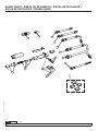
SPARE PARTS / PIEZAS DE RECAMBIOS / PIÈCES DE RECHANGE /
PEÇAS DE REPOSIÇÃO / ПРИМЕЧАНИЯ
21
17
22
18
19
4
2
11
20
24
23
8
16
7
2
1
11
10
13 6
5
4
9
12

2019_07_22-10:00
29
R. 07/19 836 829
SAMOA Industrial, S.A. · Pol. Ind. Porceyo, I-14 · Camino del Fontán, 831 · 33392 - Gijón - Spain · Tel.: +34 985 381 488 · www.samoaindustrial.com
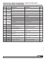
POS. PART NO. /
CÓD. DESCRIPTION DESCRIPCIÓN QTY.
1 736628
O-ring
Strainer Junta tórica
Filtro 1
1
Swivel Rótula 1
2 369604
Spring Muelle 1
Valve Válvula 1
1
Rod Empujador 1
4 369603
Cam Eje de giro 1
O-ring Junta tórica 2
Self tapping screw Tornillo 2
5 369602
Pin Pasador elástico 1
Lock/unlock button Botón de bloqueo 1
Trigger spring Muelle de bloqueo 1
Pin Pasador elástico 1
Trigger Gatillo 1
6 369224 Flexible outlet with automatic
non-drip tip. Extensión flexible con boquilla antigoteo
automática. 1
7 369226 Flexible formable outlet with
automatic non-drip tip. Extensión flexible conformable con
boquilla antigoteo automática. 1
8 369228 Flexible outlet with quarter turn
opening non-drip tip.
Extensión flexible a 90º con boquilla
antigoteo manual de apertura cuarto de
vuelta. 1
9 369230 Flexible outlet with automatic
non-drip tip. Extensión flexible a 90º con boquilla anti-
goteo automática. 1
10 369232 Rigid outlet with quarter turn opening
non-drip tip.
Extensión rígida a 60º con boquilla
antigoteo manual de apertura cuarto de
vuelta. 1
11 369234 Flexible formable outlet with quarter
turn opening non-drip tip.
Extensión flexible conformable con
boquilla antigoteo manual de apertura
cuarto de vuelta. 1
12 369222 Quarter turn opening non-drip tip. Boquilla antigoteo de apertura cuarto de
vuelta. 1
13 369221 Automatic non-drip tip. Boquilla antigoteo automática. 1
16 369606 Flange cover kit 4 colors Kit protectores de brida 4 colores 1
SPARE PARTS / PIEZAS DE RECAMBIOS / PIÈCES DE RECHANGE /
PEÇAS DE REPOSIÇÃO / ПРИМЕЧАНИЯ

2019_07_22-10:00
30 836 829 R. 07/19
SAMOA Industrial, S.A. · Pol. Ind. Porceyo, I-14 · Camino del Fontán, 831 · 33392 - Gijón - Spain · Tel.: +34 985 381 488 · www.samoaindustrial.com
SPARE PARTS / PIEZAS DE RECAMBIOS / PIÈCES DE RECHANGE /
PEÇAS DE REPOSIÇÃO / ПРИМЕЧАНИЯ
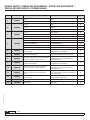
Pos. Réf. / Cód. Description Descrição Qty.
1 736628
Joint torique
Filtre Anel de vedação
Filtro 1
1
Raccord tournant Giratório 1
2 369604
Ressort Mola 1
Vanne Válvula 1
1
Poussoir Empurrador 1
4 369603
Came Eixo de giro 1
Joint torique Anel de vedação 2
Vis de serrage Parafusos 2
5 369602
Goupille élastique Passador elástico 1
Bouton de blocage /déblocage Botão de bloqueio 1
Ressort de gâchette Mola de bloqueio 1
Goupille élastique Passador elástico 1
Gâchette Gatilho 1
6 369224 Flexible droit et bec anti-goutte
automatique. Extensão flexível com ponteira
antigotejante automática. 1
7 369226 Flexible adaptable droit et bec anti-
goutte automatique. Extensão flexível adaptável com
ponteira antigotejante automática. 1
8 369228 Flexible coudé à 90º et bec anti-goutte
manuel ouverture quart de tour..
Extensão flexível 90º com ponteira
antigotejante manual de apertura
quarto de volta. 1
9 369230 Flexible coudé à 90º et bec anti-
goutte automatique. Extensão flexível 90º com ponteira
antigotejante automática. 1
10 369232 Extension à 60º et bec anti-goutte
manuel ouverture quart de tour.
Extensão rídida 60º com ponteira
antigotejante manual de apertura
quarto de volta. 1
11 369234 Flexible adaptable droit et bec anti-
goutte manuel ouverture quart de
tour.
Extensão flexível adaptável com pon-
teira antigotejante manual de apertura
quarto de volta. 1
12 369222 Bec anti-goutte manuel ouverture
quart de tour. Ponteira antigotejante manual de
apertura quarto de volta. 1
13 369221 Bec anti-goutte automatique Ponteira antigotejante automática 1
16 369606 Kit de protection de bride, 4 couleurs
différentes Kit proteção da flange, 4 cores
diferentes 1

2019_07_22-10:00
31
R. 07/19 836 829
SAMOA Industrial, S.A. · Pol. Ind. Porceyo, I-14 · Camino del Fontán, 831 · 33392 - Gijón - Spain · Tel.: +34 985 381 488 · www.samoaindustrial.com
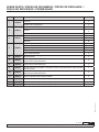
Поз. Деталь № Описание Кол-во.
1 736628
Уплотнительное кольцо сетчатого
фильтра
1
1
Поворотное соединение 1
2 369604
Пружина 1
Клапан 1
1
Стержень 1
4 369603
Кулачок 1
Уплотнительное кольцо 2
Саморез 2
5 369602
Штифт 1
Кнопка блокировки / разблокировки 1
Пружина спускового механизма 1
Штифт 1
Спусковой механизм 1
6 369224 Гибкий выходной патрубок с автоматически открывающимся герметичным
наконечником. 1
7 369226 Гибкий формуемый выходной патрубок с автоматически открывающимся
герметичным наконечником. 1
8 369228 Гибкий выходной патрубок с открывающимся на четверть оборота
герметичным наконечником. 1
9 369230 Гибкий выходной патрубок с автоматически открывающимся герметичным
наконечником. 1
10 369232 Жесткий выходной патрубок с открывающимся на четверть оборота
герметичным наконечником. 1
11 369234 Гибкий формуемый выходной патрубок с открывающимся на четверть
оборота герметичным наконечником. 1
12 369222 Открывающийся на четверть оборота герметичный наконечник. 1
13 369221 Автоматически открывающийся герметичный наконечник. 1
16 369606 Крышка выходного фланца в 4-х различных цветах 1
SPARE PARTS / PIEZAS DE RECAMBIOS / PIÈCES DE RECHANGE /
PEÇAS DE REPOSIÇÃO / ПРИМЕЧАНИЯ

2019_07_22-10:00
32 836 829 R. 07/19
SAMOA Industrial, S.A. · Pol. Ind. Porceyo, I-14 · Camino del Fontán, 831 · 33392 - Gijón - Spain · Tel.: +34 985 381 488 · www.samoaindustrial.com
For SAMOA INDUSTRIAL, S.A.
Por SAMOA INDUSTRIAL, S.A.
Pour SAMOA INDUSTRIAL, S.A.
Für SAMOA INDUSTRIAL, S.A.
Por SAMOA INDUSTRIAL, S.A.
От лица компании SAMOA INDUSTRIAL, S.A.
Pedro E. Prallong Álvarez
Production Director
Director de Producción
Directeur de Production
Produktionsleiter
Diretor de Produção
Директор по производству
SAMOA INDUSTRIAL, S.A., Pol. Ind. Porceyo, I-14 ·
Camino del Fontán, 831 · 33392 - Gijón - Spain, declares
that the product(s): 366 000
conform(s) with the EU Directive(s): 2004/108/EC
EN
SAMOA INDUSTRIAL, S.A., Pol. Ind. Porceyo, I-14 ·
Camino del Fontán, 831 · 33392 - Gijón - España,
declara que el(los) producto(s): 366 000
cumple(n) con la(s) Directiva(s) de la Unión Europea:
2004/108/CE
ES
SAMOA INDUSTRIAL, S.A., Pol. Ind. Porceyo, I-14 ·
Camino del Fontán, 831 · 33392 - Gijón - Espagne,
déclare que le(s) produit(s): 366 000
est(sont) conforme(s) au(x) Directive(s) de l’Union
Européenne: 2004/108/CE
FR
SAMOA INDUSTRIAL, S.A., Pol. Ind. Porceyo, I-14 ·
Camino del Fontán, 831 · 33392 - Gijón- Spanien,
bestätigt hiermit, dass das (die) Produkt (e): 366 000
der (den) EG-Richtlinie(n): 2004/108/EG entspricht
(entsprechen).
DE
SAMOA INDUSTRIAL, S.A., Pol. Ind. Porceyo, I-14 ·
Camino del Fontán, 831 · 33392 - Gijón- Espanha,
declara que os produtos 2100S-DO cumprem as
diretrizes da União Europeia: 366 000
2004/108/EG
PT
EC CONFORMITY DECLARATION / DECLARATION CE DE CONFORMIDAD / DÉCLARATION CE DE
CONFORMITÉ / EG-KONFORMITÄTSERKLÄRUNG / DECLARAÇÃO DE CONFORMIDADE
Сертификат соответствия:
№ ТС RU C-ES.АБ58.В.01841, срок действия с
28.07.2017 по 27.07.2020, выдан органом по
сертификации продукции «М-ФОНД» ООО
«Агентство по экспертизе и испытаниям продукции»;
Адрес 125167, Россия, г. Москва, ул. Викторенко,
дом 16, стр. 1. Телефон: +74951501658,
e-mail: [email protected]. Аттестат аккредитации №RA.
RU.11АБ58 от 07.04.2016 года.
Дата производства указана на маркировке
изделия
Транспортировка
Изделие должно транспортироваться в заводской
упаковке для защиты от повреждений и влаги.
Хранение
Изделие должно храниться запакованным, в хорошо
проветриваемом и сухом помещении.
Утилизация
Выполняйте национальные правила утилизации и
переработки отслужившего оборудования, упаковки
и принадлежностей.
RU
-
 1
1
-
 2
2
-
 3
3
-
 4
4
-
 5
5
-
 6
6
-
 7
7
-
 8
8
-
 9
9
-
 10
10
-
 11
11
-
 12
12
-
 13
13
-
 14
14
-
 15
15
-
 16
16
-
 17
17
-
 18
18
-
 19
19
-
 20
20
-
 21
21
-
 22
22
-
 23
23
-
 24
24
-
 25
25
-
 26
26
-
 27
27
-
 28
28
-
 29
29
-
 30
30
-
 31
31
-
 32
32


Samoa 363112 Instructions Manual
- Categoría
- Rociador de pintura
- Tipo
- Instructions Manual
en otros idiomas
- français: Samoa 363112
- português: Samoa 363112
Artículos relacionados
-
Samoa 365588 Instructions Manual
-
-
-
-
-
-
-
-
-