sauermann LR 110 Light Sensor or Transmitter Guía del usuario
- Tipo
- Guía del usuario


English Quick Start Guide
Light transmitter
Operating temperature, protection of the instruments and information about storage
Conditions of use (°C/%RH/m): from -10 to +50 °C; in non-condensing conditions. From 0 to 2000 m.
Protection: IP65
Storage temperature: from -10 to +70 °C.
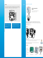
Dimensions
Symbols used
For your safety and in order to avoid any damage of the device, please follow the procedure described in
this document and read carefully the notes preceded by the following symbol:
The following symbol will also be used in this document, please read carefully the information notes
indicated after this symbol:
Connections
LR 110 light sensor has a measuring range from
0 to 10,000 lux.
46 mm 90 mm
109 mm
26 mm
Ø52 mm
Inside the front housing
1. Active switch
2. Inactive switch
3. LCC-S software
connection
4. Power supply and
output signal
5. Cable gland
1
2
Removable front face Fixed back housing
3
5
4
This connection must be made by a qualied and trained technician.
To make the connection, the transmitter must not be energized.
Vdc
ILUX or
+
-
Vdc
ILUX
+
-
+
+
-
... 5 6 7
Power supply 16-30 Vdc
A
+
-
... 5 6 7
A16-30 Vdc
2 wires
Display/regulator/PLC
passive type
2 wires
Display/regulator/PLC
active type
2 wires
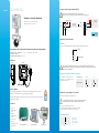
Settings and use of the transmitter
Conguration
To congure the transmitter, unscrew the 4 screws of the housing then open it. DIP switches allowing the different
settings are accessible.
To congure the transmitter, it must not be energized. Then you can make the required settings
thanks to the DIP switches as shown on the drawing below. When the transmitter is congured, you
can power it up.
1
2
3
4
Off On
Setting of the measuring unit
On-off switch
Electrical connections – as per NFC15-100 standard
Measuring unit setting – Active switch
Congurations lux fc
Combinations
To set the unit of measurement, put the on-
off switches 3 and 4 as shown in the table: 1
2
3
4
1
2
3
4
Conguration via PC
1
2
3
4
Conguration via LCC-S software (optional)
An easy and friendly conguration with the software!
Caution: The conguration of the parameters can be done either by
DIP switch, or by software (you cannot combine both solutions).
To access to the conguration via software:
- Set the switch as shown below.
- Connect the cable of the LCC-S to the connection of the transmitter
To congure the
transmitter, please
refer to the LCC-S user
manual.
Switch 1

Maintenance: please avoid any aggressive
solvent. Please protect the transmitter
and its probes from any cleaning product
containing formalin, that may be used for
cleaning rooms or ducts.
Precautions for use: please always use the device
in accordance with its intended use and within
parameters described in the technical features in order
not to compromise the protection ensured by the
device.
Français Guide rapide
Mounting
To mount the transmitter, mount the ABS plate on the wall (drilling: Ø 6 mm, screws and pins are supplied).
Insert the transmitter on the xing plate (see A on the drawing beside). Rotate the housing in clockwise
direction until you hear a “click” which conrms that the transmitter is correctly installed.
7.5 mm
8 mm
4.5 mm
40 mm
50 mm
68 mm
75 mm
37.5 mm
23.75 mm
14 mm
A
A
Capteur / transmetteur de
lumière
Tempréture d'utilisation, protection des appareils et informations sur le stockage
Conditions d’utilisation (°C/%RH/m) : de -10 à +50 °C ; en condition de non condensation. De 0 à 2000 m.
Indice de protection : IP65
Température de stockage : de -10 à +70 °C.
Dimensions
Symboles utilisés
Pour votre sécurité et an d’éviter tout endommagement de l’appareil, veuillez suivre la procédure décrite
dans ce document et lire attentivement les notes précédées du symbole suivant :
Le symbole suivant sera également utilisé dans ce document. Veuillez lire attentivement les notes
d’informations indiquées après ce symbole.
Connectiques
Le LR 110 est un capteur de lumière qui gère une
gamme de mesure de 0 à 10 000 lux.
46 mm 90 mm
109 mm
26 mm
Ø52 mm
Intérieur de la coque avant
1. Switch actif
2. Switch inactif
3. Connexion Logiciel
LCC-S
4. Bornier
d’alimentation et de
sortie
5. Presse-étoupe
1
2
Face avant mobile Boîter arrière xe
3
5
4

Seul un technicien formé et qualié peut réaliser cette opération.
Pour réaliser le raccordement, l’appareil doit être HORS-TENSION.
Réglages et utilisation du capteur
Conguration
Pour congurer le capteur, dévisser les 4 vis du boîtier puis l’ouvrir. Les switchs permettant les différents réglages
sont accessibles.
ATTENTION : Pour congurer le capteur, le mettre hors tension puis procéder aux réglages souhaités
en disposant les interrupteurs comme décrit ci-dessous. Remettre le capteur sous tension une fois
les réglages effectués.
1
2
3
4
Off On
Réglages de l’unité
Interrupteur
Raccordements électriques suivant normes NFC15-100
Réglage de l’unité de mesure – Switch actif
Congurations lux fc
Combinaisons
Pour régler l’unité de mesure, positionner les
interrupteurs 3 et 4 comme indiqué dans le
tableau ci-contre : 1
2
3
4
1
2
3
4
Conguration par PC
1
2
3
4
Conguration logiciel LCC-S (option)
Le logiciel permet une conguration plus souple.
ATTENTION : la conguration des paramètres s’effectue soit par
switch soit par logiciel. Les deux ne sont pas compatibles.
Pour accéder à la conguration par logiciel :
- Régler le switch comme indiqué ci-dessous.
- Raccorder le câble du LCC-S à la connexion du capteur.
Pour procéder à la
conguration de votre
appareil, voir la notice
du LCC-S.
Entretien :
• Éviter tous les solvants agressifs.
• Protéger l’appareil lors du nettoyage
à base de produits formolés (pièces ou
conduits).
Précautions d’utilisation : veillez à toujours utiliser
l’appareil conformément à l’usage prévu et dans les
limites des paramètres décrits dans les caractéristiques
techniques an de ne pas compromettre la protection
assurée par l’appareil.
Montage
Pour réaliser le montage mural, xer la plaque ABS au mur (perçage Ø 6 mm, vis et chevilles fournies). Insérer
le capteur dans la plaque de xation (aux points A sur le schéma) en l’inclinant à 30°. Faire pivoter le boîtier
dans le sens des aiguilles d’une montre jusqu’à l’obtention d’un clipage ferme.
7.5 mm
8 mm
4.5 mm
40 mm
50 mm
68 mm
75 mm
37.5 mm
23.75 mm
14 mm
A
A
Vdc
ILUX ou
+
-
Vdc
ILUX
+
-
+
+
-
... 5 6 7
Alimentation 16-30 Vdc
A
+
-
... 5 6 7
A16-30 Vdc
2 ls
Afcheur / régulateur
autonome de type passif
2 ls
Afcheur / régulateur
autonome de type actif
2 ls
Switch 1

Español Guía rápida
(1) Modelo ambiental / (2) Modelos posterior, a distancia y estándar.
Transmisores de nivel de iluminación
Temperatura de uso, índice de protección de los instrumentos y informaciones para almacenamiento
Condiciones de uso (°C/%RH/m) : de -10 a +50 °C ; sin condensación. De 0 a 2000 m.
Índice de protección : IP65
Temperatura de almacenamiento : de -10 a +70 °C.
Dimensiones
Símbolos utilizados
Por su seguridad y para evitar daños en el dispositivo, siga el procedimiento descrito en el presente
documento y lea atentamente las notas precedidas del siguiente símbolo:
El siguiente símbolo también se utiliza en el presente documento. Lea atentamente las notas informativas
indicadas tras este símbolo.
Connexiones
El LR 110 es un sensor de luz que maneja un
rango de medición de 0 a 10,000 lux.
46 mm 90 mm
109 mm
26 mm
Ø52 mm
Interior de la parte frontal
1. Bloque de
microinterruptores
activo
2. Bloque de
microinterruptores
inactivo
3. Conexión LCC-S
4. Bornes de
alimentación y señal
5. Prensa-estopa
1
2
Parte frontal extraible Parte trasera ja
3
5
4
Sólo un técnico cualicado puede efectuar estas conexiones.
Debe llevar a cabo esta instalación cuando el instrumento no tenga tensión.
Conguración y uso del transmisor
Conguración
Para acceder a los interruptores DIP, desatornille los 4 tornillos de la parta frontal de la caja.
Para congurar el transmisor, debe proceder a colocar los interruptores según se describe a
continuación cuando el equipo esté sin alimentación. Reestablezca la alimentación una vez haya
completado la conguración.
1
2
3
4
Off On
Ajuste de las unidades
Interruptor
Conexiones eléctricas (según normativa NFC-150)
Conguración de las unidades de medición – Bloque activo
Conguraciones lux fc
Combinaciones
Para congurar la unidad, coloque los
interruptores 3 y 4 del bloque derecho
(activo) tal y como se indica. 1
2
3
4
1
2
3
4
Conguración con LCC-S
Switch 1
1
2
3
4
Conguración con el programa LCC-S (opcional)
Una conguración exible gracias al programa LCC-S
La conguración debe realizarse a través de los interruptores DIP o
mediante programa (no pueden combinarse ambos métodos).
Para acceder a la conguración por software:
- Ajustar los interruptores previamente como se indica en el gráco.
- Conectar el cable al conector especíco en la electrónica
Para proceder a la
conguración del
equipo, consulte el
manual del programa
LCC-S.
Vdc
ILUX o
+
-
Vdc
ILUX
+
-
+
+
-
... 5 6 7
Alimentación 16-30 Vdc
A
+
-
... 5 6 7
A
16-30 Vdc
2 hilos
Regulador/PLC
tipo pasivo
2 hilos
2 hilos
Regulador/PLC
tipo activo

Mantenimiento : evite el contacto con
disolventes agresivos. Proteja el transmisor
y sus sondas de cualquier producto de
limpieza que contenga formalina.
Precauciones en el uso del dispositivo : use siempre
el dispositivo de acuerdo con la aplicación para la cual
está destinado y dentro de los parámetros descritos
en las características técnicas para no comprometer la
protección garantizada del dispositivo.
Montaje
Para realizar el montaje mural, jar la placa de ABS en la pared (suministrada con el equipo).
Tornillería : Ø 6 mm (tornillos y tacos suministrados). Colocar el equipo a la placa de jación y rotar 30°.
Hacer pivotar la caja en sentido de las agujas del reloj hasta obtener una jación segura.
7.5 mm
8 mm
4.5 mm
40 mm
50 mm
68 mm
75 mm
37.5 mm
23.75 mm
14 mm
A
A

QSG – LR 110 – 07/10/22 – Non-contractual document – We reserve the right to modify the characteristics of our products without prior notice
www.sauermanngroup.com
Download the LR 110 data sheet
Télécharger la che technique du LR 110
Descargue la cha técnica del LR 110
Download the LCC-S software user manual
Télécharger la notice d'utilisation du logiciel LCC-S
Descargue el manual de usuario del software LCC-S
https://sauermann-en.custhelp.com
Customer service portal / Portail service clients
Portal de servicio al cliente
Use our Customer service portal to contact us
Utilisez notre Portail service clients pour nous contacter
Contacte con nosotros a través del Portal de servicio al cliente
-
 1
1
-
 2
2
-
 3
3
-
 4
4
-
 5
5
-
 6
6
-
 7
7


sauermann LR 110 Light Sensor or Transmitter Guía del usuario
- Tipo
- Guía del usuario
en otros idiomas
Artículos relacionados
Otros documentos
-
 TELEMECANIQUE ALTIVAR 31 El manual del propietario
-
 Hach Chlorine Sensor Manual de usuario
-
Eurotherm ATV12 El manual del propietario
-
Lelit Kate PL82T Manual de usuario
-
Polk Audio MagniFi El manual del propietario
-
Schneider Electric altivar 58 telemecanique Manual de usuario
-
Logitech V450 Nano Cordless Laser Mouse for Notebooks Manual de usuario
-
JVC DT-V1710CG Manual de usuario
-

