Baumer FVDK 10N66Z0/S35A Instrucciones de operación
- Tipo
- Instrucciones de operación

11214494
Í?+5L~ÂÂ*Â4Î
1/8
Canada
Baumer Inc.
CA-Burlington, ON L7M 4B9
Phone +1 (1)905 335-8444
China
Baumer (China) Co., Ltd.
CN-201612 Shanghai
Phone +86 (0)21 6768 7095
Denmark
Baumer A/S
DK-8210 Aarhus V
Phone +45 (0)8931 7611
France
Baumer SAS
FR-74250 Fillinges
Phone +33 (0)450 392 466
Germany
Baumer GmbH
DE-61169 Friedberg
Phone +49 (0)6031 60 07 0
India
Baumer India Private Limited
IN-411038 Pune
Phone +91 20 2528 6833/34
Italy
Baumer Italia S.r.l.
IT-20090 Assago, MI
Phone +39 (0)2 45 70 60 65
Singapore
Baumer (Singapore) Pte. Ltd.
SG-339412 Singapore
Phone +65 6396 4131
Sweden
Baumer A/S
SE-56133 Huskvarna
Phone +46 (0)36 13 94 30
Switzerland
Baumer Electric AG
CH-8501 Frauenfeld
Phone +41 (0)52 728 1313
United Kingdom
Baumer Ltd.
GB-Watchfield, Swindon, SN6 8TZ
Phone +44 (0)1793 783 839
USA
Baumer Ltd.
US-Southington, CT 06489
Phone +1 (1)860 621-2121
www.baumer.com/worldwide
Baumer Electric AG · CH-8501 Frauenfeld
Phone +41 (0)52 728 1122 · Fax +41 (0)52 728 1144
FVDK 10N66Z0/S35A
Allgemeine Hinweise:
Bestimmungsgemässer Gebrauch: Dieses Produkt ist ein Präzisionsgerät und dient zur Erfassung von Objekten, Gegenständen und Aufbereitung bzw. Bereitstellung von Messwerten als elektrische Grösse für das
Folgesystem.Sofern dieses Produkt nicht speziell gekennzeichnet ist, darf dieses nicht für den Betrieb in explosionsgefährdeter Umgebung eingesetzt werden. Inbetriebnahme: Einbau, Montage und Justierung dieses
Produktes dürfen nur durch eine Fachkraft erfolgen. Montage: Zur Montage nur die für dieses Produkt vorgesehenen Befestigungen und Befestigungszubehör verwenden. Nicht benutzte Ausgänge dürfen nicht beschaltet
werden. Bei Kabelausführungen mit nicht benutzten Adern, müssen diese isoliert werden. Zulässige Kabel-Biegeradien nicht unterschreiten. Vor dem elektrischen Anschluss des Produktes ist die Anlage spannungsfrei
zu schalten. Wo geschirmte Kabel vorgeschrieben werden, sind diese zum Schutz vor elektromagnetischen Störungen einzusetzen. Bei kundenseitiger Konfektion von Steckverbindungen an geschirmte Kabel, sollen
Steckverbindungen in EMV-Ausführung verwendet und der Kabelschirm muss grossflächig mit dem Steckergehäuse verbunden werden.
General notes:
Rules for proper usage: This product is a precision device which has been designed for the detection of objects and parts. It generates and provides measured values issued as electrical signals for following
systems. Unless this product has not been specifically marked it may not be used in hazardous areas. Set-up: Installation, mounting and adjustment of this product may only be executed by skilled employees.
Installation: Only mounting devices and accessories specifically provided for this product may be used for installation Unused outputs may not be connected. Unused strands of hard-wired sensors must be isolated. Do not
exceed the maximum permissible bending radius of the cable. Before connecting the product electrically the system must be powered down. Where screened cables are mandatory, they have to be used in order to assure
EMI protection. When assembling connectors and screened cables at customer site the screen of the cable must be linked to the connector housing via a large contact area.
Indications d’ordre général:
Affectation: Ce produit est un appareil de précision. Il sert à la détection d’objets, de pièces, ainsi qu’au traitement et à la transmission de valeurs de mesure sous forme d’une grandeur électrique. Si ce produit
n’est pas spécialement désigné, il ne peut être utilisé dans des environnements présentant un risque d’explosion. Mise en service: L’installation, le montage et le réglage de ce produit ne peut être effectué que par
une personne spécialisée. Montage: Pour le montage, n’utiliser que les fixations et les accessoires prévus pour ce produit. Les sorties non utilisées ne doivent pas être raccordées. Dans le cas d’exécutions avec câble,
les fils non utilisés doivent être isolés. Ne pas dépasser le rayon de courbure autorisé pour le câble. Mettre impérativement l’installation hors tension avant de procéder au raccordement du produit. Dans les cas où des
câbles blindés sont demandés, ils doivent être absolument utilisés afin d’éviter les perturbations d’ordre électromagnétiques. Dans le cas où des câbles blindés avec connecteurs sont confectionnés par le client, il faut utiliser
des connecteurs conformes CEM et le blindage du câble doit être relié au connecteur.

2/8
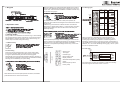
Betriebsreichweite (Einweg-Lichtleiter) Actual range Sb (through beam fiber optics) Portée de fonctionnement Sb (barrière)
Tastweite Tw (Reflex-Lichtleiter) Sensing distance Tw (diffuse fiber optics) Portée Tw (réflex)
Betriebsspannungsbereich +Vs (UL-Class 2) Voltage supply range +Vs (UL-Class 2) Plage de tension +Vs (UL-Class 2)
max. Stromverbrauch Max. supply current Consommation max.
max. Schaltstrom Max. switching current Courant de sortie max.
Spannungsabfall Voltage drop Tension résiduelle
Ansprechzeit (je nach Betriebsmodus) Response time (depending on working mode) Temps d'activation
Abfallzeit (je nach Betriebsmodus) Release time (depending on working mode) Temps desactivation
Timer Funktion / An-/Abfallverzögerung Timer function / on/off delay Ajustage temporisation /activation/désactivation
Ausgangsimpulslänge Output pulse width Durée de l'impulsion de sortie
Kurzschlussfest Short circuit protection Protégé contre courts-circuits
Verpolungsfest Reverse polarity protection Protégé contre inversion polarité
Arbeitstemperatur Temperature range Température de fonctionnement
Schutzklasse Protection class Classe de protection
FVDK 10N66Z0/S35A
940 mm (FSE 200C11002)
260 mm (FUE 200C1003)
10.5 ...26.5 VDC
30 mA
100 mA
< 2,1 VDC
0.25 ms / 0.5 ms / 1 ms / 5 ms
0.25 ms / 0.5 ms / 1 ms / 5 ms
1 ms ... 5 s
-
ja / yes / oui
ja / yes / oui
-20 °C ... +55°C
IP 40

3/8
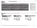
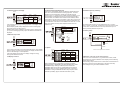
1. Bedienungselemente
2. Ausgangsfunktion
3. Schaltpunkt einstellen
Der Schaltpunkt kann manuell über die Tastatur oder über drei
unterschiedliche Teach-in Verfahren eingestellt werden.
Beim manuellen Einstellen bleibt der Sensor in Funk
tion. Beim
Teach-in schaltet der Ausgang auf OFF.
3.2 Teach-in
Es stehen drei unterschiedliche Teach-in Verfahren
zur Verfügung.
Beim Teach-in wird der optimale Schaltpunkt und der optimale
Betriebsmodus automatisch anhand der empfangenen Lichtmenge
gesetzt. Muss aus applikationstechnischen Gründen ein bestimmter
Betriebsmodus eingestellt sein, kann über die Funkt
ion „Optionen“
der Automatismus ausgeschaltet werden.
Nach dem Einteachen wird der Schaltpunkt in die Mit
te der zwei
Teachwerte gelegt.
Falls die zwei Teachwerte zu nahe beieinander geleg
en sind oder
die absolute Lichtmenge zu tief ist, wird eine Alar
minformation
angezeigt. In diesem Fall überprüfen Sie die Instal
lation und
versuchen Sie es nochmals.
Bei einem Reflex-Lichtleiter wird der Schaltpunkt a
uf den max. Wert
gelegt, bei dem der Hintergrund nicht erkannt wird.
Wird dieser Teach-in Ablauf angewendet mit einem Reflex-
Lichtleiter ohne Objekt oder Hintergrund und ein Einweg-Lichtleiter
mit einem Objekt dazwischen, wird die max. Empfindl
ichkeit des
Sensors eingestellt.
Der Schaltpunkt wird im gewählten Prozentwert zum aktuellen
Empfangswert gesetzt. Ist der gewählte Prozentwert
unmöglich wird
eine Fehlermeldung ausgegeben. In diesem Fall überp
rüfen Sie die
Installation und versuchen Sie es nochmals.
4. Funktionen
Betriebsmodus
Timer
Anzeigevarianten
Energiesparmodus
Anzeige drehen
Nachführung der Schaltschwelle
Optionen
Sendefrequenz umschalten
Fabrikzustand einstellen
4.1 Betriebsmodus
3.1 Manuelles Einstellen
Der Betriebsmodus ist eine Kombination zwischen Ansprechzeit und
Empfindlichkeit. Es existieren 3 unterschiedliche Ansprechzeiten mit
jeweils 4 Empfindlichkeitsstufen. Sollte im gewählt
en Betreibsmodus
der Sensor in der Sättigung sein, wählen sie einfach eine weiniger
empfindliche Stufe (nL4 4000 entspricht max. Empfindlichkeit).
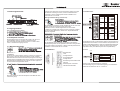
4.2 Timer
Es stehen zwei Timerfunktionen zur Verfügung:
Einschaltverzögerung und Ausschaltverzögerung. Der einstellbare
Zeitbereich für beide Timer ist von 1 ms bis 5 s.
Response times shown are for emitter frequency Fr-1.
Press
AUTO
OK
Timer types
No timer
On-delay
Off-delay
Press
AUTO
OK
–
+
Press
Press
Response
time
Maximum
display value
1ms
500µs
250µs
Sensing
types
Normal
Semi Fast
Fast
–
+
AUTO
OK
AUTO
OK
High Power
5ms
Hell- / Dunkelschaltung wählen
Hintergrundausblendung (elektronisch)

4/8
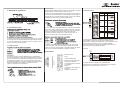
4.3
Anzeigevarianten
Es bestehen zwei Anzeigemöglichkeiten:
1. Normale Anzeige: Aktueller Wert der empfangenen
Lichtmenge
(rot) und Schaltschwelle (grün)
2. Prozentanzeige: Die aktuell empfangene Lichtmeng
e wird in
Prozent (rot) zur Schaltschwelle angezeigt (Schaltschwelle = 100%)
4.4 Energiesparmodus (Display ausschalten)
Die Stromaufnahme kann etwa um 30% gesenkt werden w
enn die
Anzeige ausgeschaltet wird. Ein kleiner grüner Balken zeigt an,
dass der Sensor immer noch zuverlässig arbeitet.
Wird der Energiesparmodus gewählt, schaltet sich die Anzeige nach
ca. 20 s aus.
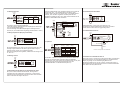
4.5 Anzeige drehen
4.6 Automatisches Nachführen der Schaltschwelle (STA)
Die „STA“ Funktion hält die Schaltschwelle, bei langsamen
Veränderungen der empfangenen Lichtmenge, in einem
festen
Verhältnis zu der empfangenen Lichtmenge. Wenn dies
e Funktion
aktive ist leuchtet die orange LED „STA“.
Falls die Schaltschwelle nicht nachgeführt werden kann, blinkt die
orange LED „STA“. Der Schaltpunkt kann bei aktiver „STA“
Funktion weder manuell noch mittels Teach-in eingestellt werden.
Falls die „STA“ Funktion eingesetzt wird überprüfen
Sie die
Applikation sorgfältig. Es kann sein, dass andere Einflüsse als die
gewollten, die Schaltschwelle nachführen.
4.7 Optionen
Die Funktion „Optionen“ ermöglicht das automatische
Setzen der
Schwelle ein-/auszuschalten und diesen Wert im EEPR
OM
abzuspeichern oder nicht. Weiter kann gewählt werde
n ob die „STA“
Funktion bei einem Power-ON geresetet wird oder nicht.
Das EEPROM lässt ca. 200'000 Schreibzyklen zu).
4.8 Sendefrequenz umschalten
Im Betriebsmodus „normal“ oder „semi fast“ kann die
Sendefrequenz umgeschaltet werden. Damit kann verhindert
werden dass sich zwei Sensoren gegenseitig stören.
4.9 Fabrikzustand einstellen
–
+
AUTO
OK
Press
Press
AUTO
OK
Normal
display
Stability safety
margin
indication
Preset value
Incoming
light level
Stability
safety
margin
P *
Menu
Display
(green)
Display
(red)
Indication
type
When the stability safety margin is indicated, “P” is always displayed.
Disable monitor sleep
Enable monitor sleep
Press
Press
AUTO
OK
AUTO
OK
–
+
Do not invert
Invert
–
+
Press
Press
AUTO
OK
AUTO
OK
Timer types
When STA is
disabled
Setting of
the STA rate
When STA is enabled
STA is disabled
STA is enabled
Press
AUTO
OK
AUTO
OK
AUTO
OK
–
+
–
+
Press
AUTO
OK
*Between 50 and 95 P, STA can be set in increments of 5 P.
–
+
AUTO
OK
Press
Press
AUTO
OK
○
○
○ ○
○
○
○
Menu
Automatic
sensitivity
switching
STA
reset upon
power-up
EEPROM
Storage
–
+
Press
Press
AUTO
OK
AUTO
OK
Response times for Fr-2 differ from those for Fr-1.
Do not initialize
Initialize
Initialize
Do not initialize
Return to normal operation after initialization
Press
AUTO
OK
Press
AUTO
OK
–
+
5. Verhalten bei fehlerhaftem Teach-in
Wenn beim Teach-in Vorgang ein Fehler passiert (Bsp: ungenügender
Kontrastunterschied, zu wenig Empfangssignal), wird dies auf dem
Display angezeigt und der Schaltausgang bleibt auf 0V.
Der Ausgang bleibt auf 0V, bis ein erneutes, erfolgreiches Teach-in
durchgeführt oder das fehlgeschlagene Teach-in mittels "FUNC/CAN-
CEL"-Taste manuell quittiert wurde.

5/8
1. Key pad
2. Operation mode
3. Tuning modes
Tuning mode can be selected from manual tuning, in which settings
are changed directly by button operation an 3 types
of auto-tuning.
Target detection continues to function during manua
l tuning, but
control output turns OFF during auto-tuning.
3.1 Manual tuning
3.2 Auto tuning
Auto-tuning can be selected from 3 types: 2-point tuning, BGS
tuning (max. sensitivity setting) and percent tunin
g. During auto-
tuning, the optimal sensitivity level for the incoming light is
automatically set by the automatic sensitivity switching. However, if
a fixed sensitivity is desired for auto-tuning, the automatic sensitivity
switching can be disabled by the option setting.
After detection with the work piece present and abs
ent, the middle
point between the 2 is used as the set value.
When the difference in received light level between the 2 points is
small or when absolute light level is low, a setting error may occur.
In this case, check the sensor installation conditions and then carry
out the auto tuning again.
For a diffuse-scan fiber unit with no work piece present, the
maximum value at which the background is not detect
ed is used as
the set value.
If BGS tuning is executed for a diffuse scan fiber unit without a
background or target object present, or a thru-scan fiber unit with a
target object present, the value can be set at the
low limit (max.
sensitivity setting).
Uses a specified percentage of the incoming light l
evel as the set
value. If setting at the specified percentage is no
t possible, a setting
error will occur. In this case change the sensor’s installation
conditions or the specified percentage and the carry out the auto
tuning again.
4. Functions
Sensing type
Timer type
Indication type
Monitor sleep mode
Display inversion
Self threshold adjustment (STA)
Option
Emitter frequency switch
Factory setup
4.1 Sensing types
Sensing types are a combination of a response time and a
sensitivity level. There are 3 response times (Ft/S
F/nL) and 4
incoming light sensitivity levels (4/3/2/1 in desce
nding order of
sensitivity), therefore there are 12 sensing types.
If configuration is
not possible due to incoming light saturation caused by close-range
detection, etc., use a lower sensitivity sensing type (**3/**2/**1) and
then do an operational check.
4.2 Timer type
Two output timer functions are available: on-delay
and off-delay.
The time range for each timer is from 1 ms to 5 s.
Response times shown are for emitter frequency Fr-1.
Press
AUTO
OK
Timer types
No timer
On-delay
Off-delay
Press
AUTO
OK
–
+
Press
Press
Response
time
Maximum
display value
1ms
500µs
250µs
Sensing
types
Normal
Semi Fast
Fast
–
+
AUTO
OK
AUTO
OK
High Power
5ms

6/8
4.3
Incoming light level display
Two methods of displaying incoming light level on t
he digital display
can be selected.
Normal display (initial mode): Displays the current incoming light
level (red) and the set value (green)
Stability safety margin indication: The letter P (green) and the ratio
(in %) if the incoming light level (red) to the detection threshold are
displayed.
4.4 Monitor sleep mode
The current consumption can be decreased about 30%
if the display
will be turned off. A green moving point in the display shows that the
sensor is still working in normal operation.
If using the display-off function, the display chan
ges to energy
saving mode after 20 seconds.
4.5 Display inversion
4.6 Self threshold adjustment STA
This function automatically adjusts the detection threshold using a
given ratio of the threshold to the incoming light level. The auto-
adjustment of the threshold is carried out at regular intervals
(approx. every 3 s). When STA is enabled, the STA indicator is lit. If
the threshold is not adjusted due to the incoming light level fall in
below the limit, the indicator blinks. When STA is
enabled, neither
manual tuning nor auto-tuning is possible. If STA w
ill be used, check
its operation in advanced. If the incoming Light le
vel fluctuates due
to a combination of the sensor and a diffuse scan fiber unit or a slow
work piece speed, STA may fail to adjust the threshold to the
expected one.
4.7 Option
Option settings allow a combination of automatic sensitivity
switching saving to EEPROM and enabling/disabling S
TA reset.
EEPROM storage: Settings modified by STA are stored
in
EEPROM. When the function is enabled settings are s
tored in
EEPROM. When function is disabled settings are not
stored in
EEPROM. If writing to EEPROM would be very frequent, select
“disabled” (durability: approx. 200’000 erase-write
cycles).
4.8 Emitter frequency switching
The emitter LED frequency can be selected from Fr-1
and Fr-2
(when “normal” or “semi fast” is selected). Even if
fiber units are next
to each other, mutual interferences can be prevente
d for up to 2
units by selecting different frequencies.
4.9 Factory setup
–
+
AUTO
OK
Press
Press
AUTO
OK
Normal
display
Stability safety
margin
indication
Preset value
Incoming
light level
Stability
safety
margin
P *
Menu
Display
(green)
Display
(red)
Indication
type
When the stability safety margin is indicated, “P” is always displayed.
Disable monitor sleep
Enable monitor sleep
Press
Press
AUTO
OK
AUTO
OK
–
+
Do not invert
Invert
–
+
Press
Press
AUTO
OK
AUTO
OK
Timer types
When STA is
disabled
Setting of
the STA rate
When STA is enabled
STA is disabled
STA is enabled
Press
AUTO
OK
AUTO
OK
AUTO
OK
–
+
–
+
Press
AUTO
OK
*Between 50 and 95 P, STA can be set in increments of 5 P.
–
+
AUTO
OK
Press
Press
AUTO
OK
○
○
○ ○
○
○
○
Menu
Automatic
sensitivity
switching
STA
reset upon
power-up
EEPROM
Storage
–
+
Press
Press
AUTO
OK
AUTO
OK
Response times for Fr-2 differ from those for Fr-1.
Do not initialize
Initialize
Initialize
Do not initialize
Return to normal operation after initialization
Press
AUTO
OK
Press
AUTO
OK
–
+
5. Behavior if an error occurs during Teach-in
If an error occurs while teach-in (e.g. insufficient contrast, insuffi-
cient light level), it will be indicated on the display and the switching
output remains at 0V.
The switching output remains at 0V until another successful teach-in
has been carried out or the failed teach-in has been manually
acknowledged using the "FUNC/CANCEL" button.

7/8
1. Eléments de commande
2. Fonction de sortie
3. Réglage du point de commutation
Le point de commutation peut être réglé manuellement sur le clavier
ou au moyen des trois procédés différents d’apprentissage (Teach-
in). Lors du réglage manuel, le détecteur reste en fonction. Lors du
Teach-in, la sortie commute sur OFF.
3.1 Réglage manuel
3.2 Teach-in
On dispose de trois procédures différentes pour l’a
pprentissage.
Lors de cette opération, le point de commutation ai
nsi que le mode
de service optimaux sont déterminés automatiquement en fonction
de la quantité de lumière reçue. Si, pour des raisons techniques
spécifiques à l’application, il s’avère nécessaire de choisir un mode
de service déterminé, il est possible, en utilisant
la fonction
„Options“, de déclencher l’automatisme.
Après l’opération d’apprentissage, le point de commutation est placé
au milieu des deux valeurs Teach-in. Dans le cas où
les deux valeurs d’apprentissage sont trop prêtes l’une de l’autre ou,
si encore, la quantité de lumière en valeur absolue est trop faible, un
message de mise en garde est affiché. Dans ce cas,
il faut contrôler
l’installation et recommencer ensuite l’apprentissa
ge.
Pour un conducteur de lumière à réflexion
,
le point de commutation
est fixé sur la valeur maximum pour laquelle l’arrière-plan n’est pas
reconnu. Si on utilise cette variante de Teach-in avec un conducteur
de lumière à réflexion sans objet ou sans arrière-p
lan et un
conducteur de lumière simple avec un objet entre les deux, le
détecteur est alors réglé sur la sensibilité maximum.
Le point de commutation est fixé selon la valeur du
pourcentage
choisie par rapport à la valeur de réception actuelle. Si la valeur
choisie en pourcent est impossible, un message d’erreur est généré.
Dans ce cas, contrôlez l’installation et essayez à
nouveau.
4. Fonctions
Mode de service
Timer
Variantes d’affichage
Mode économique d’énergie
Faire pivoter l’afficheur
Accompagnement du seuil de
commutation
Options
Commutation de la fréquence
émettrice
Réglage sur état d’usine
4.1 Mode de service
Le mode de service est une combinaison entre le tem
ps de réaction
et la sensibilité. Il existe 3 temps de réaction di
fférents avec
respectivement 4 degrés de sensibilité. Si, pour le
mode de service
choisi, le détecteur devait se trouver en état de saturation,
choisissez simplement un degré de sensibilité moins
élevé (nL4
4000 correspond à la sensibilité maximum)
4.2 Timer
On dispose de deux fonctions Timer. Retardement à
l’enclenchement et retardement au déclenchement. La plage de
réglage pour les deux Timer est de 1 ms à 5 s.
Response times shown are for emitter frequency Fr-1.
Press
AUTO
OK
Timer types
No timer
On-delay
Off-delay
Press
AUTO
OK
–
+
Press
Press
Response
time
Maximum
display value
1ms
500µs
250µs
Sensing
types
Normal
Semi Fast
Fast
–
+
AUTO
OK
AUTO
OK
High Power
5ms

8/8
4.3 Variantes d’affichage
Il existe deux posibilités d’affichage:
1. Affichage normal : valeur actuelle de la quantité de lumière reçue
(rouge) et seuil de commutation (vert)
2. Affichage en pourcent : la valeur actuelle de la
quantité de
lumière reçue est affichée en pourcent (rouge) par rapport au seuil
de commutation (seuil de commutation = 100%)
4.4 Mode économique d’énergie (déclencher l’afficheur)
La consommation de courant peut être réduite de 30% environ
lorsque l’afficheur est déclenché. Un petit trait v
ert indique que le
détecteur travaille toujours de façon fiable.
Lorsqu’on choisi le mode économique d’énergie, l’afficheur s’éteint
après environ 20 s.
4.5 Faire pivoter l’afficheur
4.6 Accompagnement automatique du seuil de commutation
(STA)
La fonction „STA“ maintient le seuil de commutation
lors de
changements lents de la lumière reçue dans un rapport fixe par
rapport à la lumière reçue. Lorsque cette fonction
est active, la LED
orange „STA“ reste allumée.
Dans le cas où le seuil de commutation ne peut être
accompagné,
la LED orange „STA“ clignote. Lorsque la fonction
„STA“ est active,
le point de commutation ne peut être réglé manuellement ni par la
procédure Teach-in. Dans le cas où la fonction „STA
“ est utilisée,
contrôlez avec soin l’application. Il est possible que d’autres
influences que celles souhaitées assurent l’accompa
gnement du
seuil de commutation.
4.7 Options
La fonction „Options“ rend possible d’activer ou d
e déclencher la
fixation automatique du seuil de commutation et de mémoriser cette
valeur dans un EEPROM.
De plus, on peut choisir si lors d’un Power-ON la f
onction „STA“ doit
être réinitialisé ou non.
L’EEPROM permet environ 200'000 cycles d’écriture
4.8 Commutation de la fréquence émettrice
En mode de service „normal“ ou „semi fast“, la fréquence émettrice
peut être commutée. Ceci permet d’éviter que deux d
étecteurs se
gênent mutuellement.
4.9 Réglage sur état d’usine
–
+
AUTO
OK
Press
Press
AUTO
OK
Normal
display
Stability safety
margin
indication
Preset value
Incoming
light level
Stability
safety
margin
P *
Menu
Display
(green)
Display
(red)
Indication
type
When the stability safety margin is indicated, “P” is always displayed.
Disable monitor sleep
Enable monitor sleep
Press
Press
AUTO
OK
AUTO
OK
–
+
Do not invert
Invert
–
+
Press
Press
AUTO
OK
AUTO
OK
Timer types
When STA is
disabled
Setting of
the STA rate
When STA is enabled
STA is disabled
STA is enabled
Press
AUTO
OK
AUTO
OK
AUTO
OK
–
+
–
+
Press
AUTO
OK
*Between 50 and 95 P, STA can be set in increments of 5 P.
–
+
AUTO
OK
Press
Press
AUTO
OK
○
○
○ ○
○
○
○
Menu
Automatic
sensitivity
switching
STA
reset upon
power-up
EEPROM
Storage
–
+
Press
Press
AUTO
OK
AUTO
OK
Response times for Fr-2 differ from those for Fr-1.
Do not initialize
Initialize
Initialize
Do not initialize
Return to normal operation after initialization
Press
AUTO
OK
Press
AUTO
OK
–
+
5. Comportement si une erreur survient lors du Teach-in
Si une erreur se produit pendant l'apprentissage (par exemple, un contraste
insuffisant, un niveau de signal insuffisant)
Cela sera indiqué sur le Display et la sortie de commutation restera à 0V.
La sortie de commutation reste à 0V jusqu'à ce qu'un autre apprentissage
ait été exécuté avec succès ou que l'apprentissage erroné ait été acquitté
manuellement en utilisant le bouton "FUNC / CANCEL".
-
 1
1
-
 2
2
-
 3
3
-
 4
4
-
 5
5
-
 6
6
-
 7
7
-
 8
8


Baumer FVDK 10N66Z0/S35A Instrucciones de operación
- Tipo
- Instrucciones de operación
en otros idiomas
Artículos relacionados
-
Baumer FVDK 10N66Y0 Instrucciones de operación
-
-
-
-
-
-
-
Baumer FVDK 10P66Y0/S35A Ficha de datos
-
-
Otros documentos
-
SICK GLL170T Instrucciones de operación
-
-
-
SICK WLL180T Instrucciones de operación
-
-
AVENTICS Sensor, series SN6 El manual del propietario
-
-
 BGS technic 8633 Manual de usuario
