Kenmore 911.47712 Guía de instalación
- Categoría
- Hornos
- Tipo
- Guía de instalación

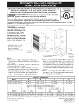
Installation
Instructions
30" Built-In Wall Oven
911.47712,47714,47719,47752,47754,47759,
49042,49043,49044,49049,49052,49053,
49054,49059
I If you have questions, contact our website at: www.sears.com I
Before You Begin
Read these instructions carefully and completely.
• IM PO RTANT-save these
instructions for local inspector's use.
• IMPORTANT-observe all
governing codes and ordinances.
• Note to Installer--Be sure to leave these
instructions with the consumer.
• Note to Consumer--Keep these
instructions for future reference.
• Proper installation is the responsibility
of the installer and product failure due
to improper installation is NOT covered
under the warranty.
• NOTE--This appliance must be properly
grounded.
•ATTENTION INSTALLER
All electric wall ovens must be hard wired
(direct wired) into an approved junction
box, A plug and receptacle is NOT permitted
on these products,
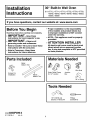
Parts Included
Metal
Bottom Trim
Screws For
Installation Plastic
Bottom Trim
Materials Needed
Strain Relief Clamp
for 1/2" conduit
@
Junction
Box
Wire Nuts
36" of String
Tools Needed
1/8" Drill Bit and
Electric or Hand Drill
Phillips
Screwdriver
229c4053P499-4
31-10518-4 243JR
1

Installation Instructions
IMPORTANT SAFETY INSTRUCTIONS
For Your Safety
• Be sure your oven is installed properly by
a qualified installer or service technician.
• Be sure the oven is securely installed in a
cabinet that is firmly attached to the house
structure. Weight on the oven door could
cause the oven to tip and result in injury.
Never allow anyone to climb, sit, stand or
hang on the oven door.
• Make sure the cabinets and wall coverings
around the oven can withstand the
temperatures (up to 200°F) generated
by the oven.
WARNING: The electrical
power to the oven supply line
must be shut off while line
connections are being made. Failure
to do so could result in serious injury
or death.
Electrical
Requirements
This appliance must be supplied with the
proper voltage and frequency, and connected
to an individual, properly grounded branch
circuit, protected by a circuit breaker or fuse
having amperage as noted on rating plate.
(Rating Plate is located on oven frame.)
We recommend you have the electrical wiring
and hookup of your oven connected by a
qualified electrician. After installation, have the
electrician show you where your main oven
disconnect is located.
Check with your local utilities for electrical
codes which apply in your area. Failure to wire
your oven according to governing codes could
result in a hazardous condition. If there are no
local codes, your oven must be wired and fused
to meet the requirements of the National
Electrical Code, ANSI/NFPA No. 70-Latest
Edition. You can get a copy by writing:
National Fire Protection Association
Batterymarch Park
Quincy, MA 02269
Effective January 1, 1996, the National
Electrical Code requires that new, but not
existing, construction utilize a four-conductor
connection to an electric oven. When installing
an electric oven in new construction, a mobile
home, recreational vehicle or an area where
local codes prohibit grounding through the
neutral conductor, follow the instructions in
the section on NEW CONSTRUCTION AND
FOUR-CONDUCTOR BRANCH CIRCUIT
CONNECTION.
You must use a three-wire, single-phase A.C.
208Y/120 Volt or 240/120 Volt, 60 hertz
electrical system. If you connect to aluminum
wiring, properly installed connectors approved
for use with aluminum wiring must be used.
2

Installation Instructions
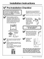
Pre-lnstallation Checklist
ALL INSTALLATION INFORMATION
ON THE FOLLOWING PAGES IS TO
BE USED FOR SINGLE AND DOUBLE
OVEN INSTALLATION!
Remove packaging materials.
Check behind hinges and under
false bottom. Remove labels on the
outside of the door, plastic on trims
and panel, all tape around the oven,
and any shipping screws securing
the oven to the base pad.
Oven Racks
Broiler Pan
and Grid Literature
Pack
Open oven door and remove literature
pack, broiler pan and grid, and oven
racks.
Remove Installation Instructions from
literature pack and read them carefully
before you begin.
Be sure to place all literature, Use and
Care, Installations, etc. in a safe place
for future reference.
m
Door removal is not a requirement for
installation of the product, but is an
added convenience. To remove the door:
Open the oven door as far as it will go.
Push both hinge Hinge
_ _'qb,,. Unlocked
locks down toward . ._i_l /
',_'I Position
the door frame, Hmgei/_,i
to the unlocked s_ot _
position. This may
require a flat blade Hinge
screwdriver. Arm
DO NOT LIFT THE DOOR
BY THE HANDLE!
Place hands on both sides of
the door, and close the oven
door to the removal position.
This is half way between the
broil stop and fully closed.
[_ Lift door up and
out until the
hinge arms
clear the slots.
Hint e Clears Slot
NOTE: The oven door is very heavy, Be sure
you have a firm grip before lifting the oven
door off the hinges, Use caution once the
door is removed. Do not lay the door on its
handle, This could cause dents or scratches,
(Continued on following page)
3

Installation Instructions
[_ Pre-lnstallation Checklist cont.
d
Place the oven on a table or platform
even with the cutout opening.
(Platform must support 150 Ibs. single,
275 Ibs. double.)
Remove the bottom trim from the top
of the oven. It will be installed at the
end of the installation process. The
trim is wrapped separately and taped
to the top of the unit.
4

Installation Instructions
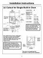
I-A-11Cutout for Single Built-In Oven
Allow 11/16" for
overlap of oven
over side edges
of cutout
21
Allow a minimum of
21" for clearance to
adjacent corners,
drawers, walls, etc.
when door is open
Cutout Cabinet Width 30"
Width
28 1/2" Min.
Between
inside Walls
Must Be
At Least
28 1/2- Wide
Allow 1" minimum
for overlap of
oven top and and
1_/4"for bottom
of cutout
Cabinet
Width
30"
I
I
I
Height
27 1/4" Min. i
27 5/16" Max,_
Recommended
minimum cutout
location from
floor 32 1/2"
Junction Box
22" to
Bottom of
Junction Box
Recommended
Minimum
Cutout Location
from Floor
Cutout Depth
Cutout Width
Cutout Height
32 1/2"
23 1/2" Min.
28 1/2" Min.
28 5/8" Max.
27 1/4" Min.
27 5/16" Max.
NOTE: If the cabinet does not
have a front frame and the
sides are less than 3/4" thick,
shim both sides equally to
establish the cutout width.
If the cabinet does not have a solid bottom,
two braces or runners must be installed
level with the bottom of the cutout to
support the weight of the oven. For single
ovens, the runners and braces must
support 150 Ibs.
NOTE: If marks, blemishes or the
cutout opening are visible above the
installed oven, it may be necessary to
add wood shims under the runners and
front trim until the marks or opening
are covered.
Suitable
Bracing
to Suppo_
Runners--
21 5/8"
Over Centerline
of Cabinet
-- 2"x4"or
equivalent
runners
level with
the bottom
of cutout
This oven is not approved for
stackable or side by side installation.
5

Installation Instructions
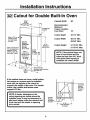
Cutout for Double Built-In Oven
Allow 11/16" for
overlap of oven
over aide edgea
of cutout
Allow a minimum of
21" for clearance to
adjacent corners_
drawers, walls, etc.
when door is open
21"
Cutout
Width
28 l/2"Min,
<--28 518" Max. -'_
Opening
Between
Inside Wails
Must Be
At Least
28 1/2" Wide
Allow 1"
minimum for
overlap of oven
top and 1V¢'
for bottom
of cutout
_ 5"fJunction Box
47" to
Bottom of
Junction Box
Height
51 13116" Min.
15/16" Max.
_._-_'_ _ Recomn_ended
30"_-_-L I minimum cutout location
Cab'met_--_____rom ,floor 12"
Width
Cabinet Width 30"
Recommended
Minimum
Cutout Location
from Floor
Cutout Depth
Cutout Width
Cutout Height
12"
23 1/2" Min.
28 1/2" Min.
28 5/8" Max.
51 13/16" Min.
51 15/16" Max.
NOTE: If the cabinet does not
have a front frame and the
sides are less than 3/4" thick,
shim both sides equally to
establish the cutout width.
If the cabinet does not have a solid bottom,
two braces or runners must be installed
level with the bottom of the cutout to
support the weight of the oven. For double
ovens, the runners and braces must
support 275 Ibs.
NOTE: If marks, blemishes or the
cutout opening are visible above the
installed oven, it may be necessary to
add wood shims under the runners and
front trim until the marks or opening
are covered.
Suitable
Bracing
to Support
Runners --
_21 5/8"_
r Centerline /
of Cabinet
--2"x4"or
equivalent
runners
level with
bottom of
cutout
6

Installation Instructions
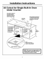
I_ Cutout for Single Built-In Oven
Under Counter
Gas or electric cooktops may
be installed over this oven.
See cooktop installation
instructions for cutout size.
See label on top of oven for
approved cooktop models.
Top and/or side fillers
may
between existing
cabinets. Be sure
they are attached
securely, since they
will anchor the oven
• in the cabinet.
240V / 208V
Junction Box
Location
1" overlap for
top of oven and
_._11/16" overlap
for side edges
of cutout
Gas and electrical connections for
30" gas cooktop must be located
in an adjacent accessible location
to the right. For 36" gas cooktop,
the connections may be made
to the left.
22" Min. 36"
Above Typical
Support Countertop
Platform Height
I
sJ*_
3/4"
Support Platform
Required
5 9/16"
Reference dimension for
maximum support height with
typical 36" countertop height
MUST SUPPORT 150 LBS.
II installed under a solid disk, induction III
or downdraft modular cooktop.
7

Installation Instructions
I-B-]Electrical Connections
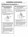
ATTENTION INSTALLER
All electric wall ovens must be hard wired
(direct wired) into an approved junction
box. A plug and receptacle is NOT permitted
on these products.
DO NOT shorten the flexible conduit.
The conduit strain relief clamp must be
securely attached to the junction box
and the flexible conduit must be securely
attached to the clamp. If the flexible
conduit will not fit within the clamp, do not
install the oven until a clamp of the proper
size is obtained.
NOTE TO ELECTRICIAN: The 3 power
leads supplied with this appliance are
UL recognized for connection to heavier
gauge household wiring. The insulation
of these 3 leads is rated at temperatures
much higher than the temperature rating
of household wiring. The current carrying
capacity of the conductor is governed
by the wire gauge and the temperature
rating of the insulation around the wire.
WARNING: Improper
connection of aluminum house
wiring to copper leads can
result in an electrical hazard or fire.
Use only connectors designed for
joining copper to aluminum and follow
the manufacturer's recommended
procedure closely.
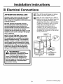
Turn off the circuit breaker or remove
fuses to the oven branch circuit.
With the oven supported on a table or
platform in front of the cabinet opening,
connect the flexible conduit to the
electrical junction box as shown below.
Position the conduit in such a manner
that it will lie on top of the oven in
a natural loop when the oven is
installed. You will need to purchase
an appropriate strain relief clamp to
complete the connection of the conduit
to the junction box.
Junction Box ,,
Location -t-5-4-
Paceoe o s_l _-_ 1/ (notincluded)
support to assist in '_ must be used at
connecting conduit Junction Box
8 (Continued on following page)

Installation Instructions
I-B-]Electrical Connections cont.
New Construction and
Four Conductor Branch
Circuit Connection
• When installing in new construction, or
• When installing in a mobile home, or
• When installing in a recreational vehicle, or
• When local codes do not permit grounding
through neutral:
a. Cut the neutral (white) lead from the crimp.
Re-strip the neutral (white) lead to expose
the proper length of conductor.
_ Junction Box
Cover
b. Attach the appliance grounding lead (green
or bare copper) in accordance with local
codes. If the residence grounding conductor
is aluminum, see WARNING on page 8.
c. Connect the oven neutral (white) lead to
the branch circuit neutral (white or gray)
in accordance with local codes, using a
wire nut.
d. Connect the oven red lead to the branch
circuit red lead and the oven black lead to
the branch circuit black lead in accordance
with local codes, using wire nuts. If the
residence red, black or white leads are
aluminum conductors, see WARNING on
page 8.
e. Install Junction Box Cover.
Three-Conductor Branch
Circuit Connection
When connecting to a three-conductor branch
circuit, if local codes permit:
a. Connect the bare oven ground conductor
with the crimped neutral (white) lead to
the branch circuit neutral (white or gray
in color), using a wire nut.
b. Connect the oven red lead to the branch
circuit red lead in accordance with local
codes, using a wire nut.
c. Connect the oven black lead to the branch
circuit black lead in accordance with local
codes, using a wire nut. If the residence
red, black or white leads are aluminum
conductors, see WARNING on page 8.
d. Install Junction Box Cover.
9

Installation Instructions
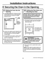
Securing the Oven in the Opening
Sliding the Oven Into the
Opening
a. Loop (do not tie) a 36" string around the
conduit before the oven is slid into place.
This will keep the conduit from falling
behind the oven.
Pull out on
string loop
while pushing
the oven into
BB the cabinet
b. Lift oven into cabinet cutout using the oven
opening as a grip. Carefully push against
oven front frame. Do not push against
outside edges.
c. As you slide the oven back, pull the string
so that the conduit will lie on top of the
oven in a natural loop.
d. When you are sure the conduit is out of the
way, slide the oven 3/4 way back into the
opening. Remove the string by pulling on
one end of the loop.
I-_ Drilling the Pilot Holes and
Mounting the Oven
NOTE: Before drilling the pilot holes,
make sure the oven is pushed as far
back into the opening as it will go
and centered.
a. Drill holes through the mounting holes (top
and bottom) of the side trim, for the #8
screws provided.
The screws must
be a minimum of
1/4" from the front
of the cutout.
_i WARNING: Mounting
screws must be used. Failure to
do so could result in the oven
falling out of the cabinet causing
serious injury.
w
b. Secure the oven to cabinet with screws
provided.
NOTE: If the cabinet is particle board, you
must use #8 x 3/4" particle board screws.
These may be purchased at any hardware
store.
10 (Continued on following page)

Installation Instructions
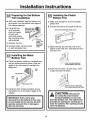
I-_ Preparing for the Bottom
Trim Installation
a. With oven installed, take the bottom trim
and center it on the bottom front edge of
the cabinet opening.
b. Using the trim
as a template,
mark the center
of each slot
(two total) where
the mounting holes
will be drilled.
With Lower Trim
in Position, Mark
(2) Mounting Hole
Locations
c. Remove the trim.
d. Drill pilot holes into the center
of each template mark.
Remove
Lower Trim
Before
Pro-drilling
Mounting
Holes
Installing the Metal
Bottom Trim
a. Place the bottom metal trim centered over
the pro-drilled mounting holes. Tape the
edges of the trim down to maintain the
alignment.
Side
Trim
Trim
Side
Trim -
\
Metal LowerTrim
b. Using two trim screws provided, secure
the bottom trim to the bottom edge of the
cabinet.
IMPORTANT: If this unit is ever
removed from the cabinet or the oven
is ever pulled out for service, the trim
must be removed first or damage to
the trim will occur.
I-_ Installing the Plastic
Bottom Trim
a. Make sure flat side is up on the plastic
bottom trim.
b. Find the key slot on the back of the trim.
Key Hole Slot and Wide Flange at Top
c. Match the key slot with the rivet on the
bottom of the side trim, and lower the trim
onto the rivet.
d. Push the trim down, at both ends, until it
snaps securely into place.
CAUTION: Be sure you
do not tip the oven forward
during installation or you may
bend the bottom trim. The bottom trim
provides an opening for cooling air to
enter the cabinet. This opening should
never be blocked.
11

Installation Instructions
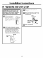
Replacing the Oven Door
NOTE: The oven door is heavy, You
may need help lifting the door high
enough to slide it into the hinge slots,
Do not lift the door by the handle,
[_Liftthe oven door by
placing one hand on
each side. The door is
heavy, so you may need
help. Do not lift the door
by the handle.
J
I-D-_ With the door at the same angle as
the removal position (half way between
the closed and broil stop position,
seat the notch of the hinge arm into
the bottom edge of the hinge slot.
The notch of the hinge arm must be
fully seated into the bottom of the slot.
Hinge Arm
Bottom Edg_ /
of Slot
Hinge Notch
I-_ Open the oven door as far as it
will open.
['_ Push the hinge locks up against the
front frame of the oven cavity, to the
locked position.
Hinge in
Locked Position
Notch of Hinge
Securely Fitted
into
Hinge Slot
I-D--_ Close the oven door.
12

Installation Instructions
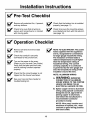
Pre-Test Checklist
Remove all protective film, if present,
and any stickers.
Check to be sure that all wiring is
secure and not pinched or in contact
with moving parts.
[_ Check that the bottom trim is installed
properly (see page 11).
[_ Check to be sure the mounting screws
are installed and flush with the side trim
(see page 10).
Operation Checklist
Remove all items from the inside
of the oven.
Check that conduit is securely
connected to the junction box.
Turn on the power to the oven.
(Refer to your Use and Care Guide.)
Verify that the bake and broil units,
and all cooking functions operate
properly.
Check that the circuit breaker is not
tripped nor the house fuse blown.
See your Use and Care Guide for
troubleshooting list.
NOTE TO ELECTRICIAN: The power
leads supplied with this appliance
are UL recognized for connections
to larger gauge household wiring.
The insulation of these leads is
rated at temperatures much higher
than the temperature rating of
household wiring. The current
carrying capacity of a conductor
is governed by the wire gauge and
also the temperature rating of the
insulation around the wire.
NOTE: ALUMINUM WIRING
A. WARNING: IMPROPER
CONNECTION OF ALUMINUM
HOUSE WIRING TO THE COPPER
LEADS CAN RESULT IN AN
ELECTRICAL HAZARD OR FIRE,
S.
Splice copper wires to aluminum
wiring using special connectors
designed and UL approved for
joining copper to aluminum,
and follow the manufacturer's
recommended connector
procedure closely.
NOTE: Wire used, location and
enclosure of splices, etc., must
conform to good wiring practice
and local codes.
13

NOTES
14

Instrucciones
de instalacibn
Horno de pared empotrado
de 30"
911.47712,47714,47719,47752,47754,47759,
49042,49043,49044,49049,49052,49053,
49054,49059
I &Preguntas? Visite nuestro sitio en la Web: www.sears.com I
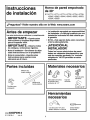
Antes de empezar
Lea estas instrucciones cuidadosa y completamente.
• IMPORTANTE-Guarde estas
instrucciones y tdngalas disponibles
para el inspector local.
• IMPORTANTE-observe todos
los cbdigos y ordenanzas vigentes.
• Nota al instalador--Cerciorese de dejar
estas instrucciones con el propietario.
• Nota al consumidor--Guarde estas
instrucciones para usarlas como
referencia en el futuro.
• La instalacibn apropiada es responsabilidad
del instalador y la falla del producto pot una
instalacibn incorrecta NO estd cubierta por
la garantfa.
• NOTA--Este aparato debe estar conectado
a tierra adecuadamente.
f
• iATENCION AL
INSTALADOR!
Todos los hornos electrbnicos de pared
deben ser cableados directamente en una
caja de conexion aprobada. Un "enchufe-
receptaculo" NO ES permitido en estos
productos.
Partes incluidas
Moldura de
fondo metalica
Tornillos para
instalacion
Moldura de
fondo pl&stica
Materiales necesarios
Abrazadera de alivio
de presi6n para
conducto de 1/2"
Tuercas para
alambres
Caja de
conexion
Cord6n de 36"
Herramientas
necesarlos
Unabroca de 1/8" para
taladro el6ctricoo manual
Destornillador
de estrella
229c4053P499-4
31-10518-4 243JR
1

Instrucciones de instalacibn
INSTRUCCIONES DE SEGURIDAD
IMPORTANTES
Para su uridad
• Cerci6rese de que su horno sea instalado
adecuadamente por un instalador calificado
o por un t6cnico de servicio.
• Cerci6rese de que su horno est6 firmemente
instalado en un gabinete que este firmemente
adherido a la estructura de la casa. El peso
sobre la puerta del horno podfia causar que el
horno se voltee resuttando en lesiones. Nunca
permita que nadie se suba, se siente, se pare o
se cuelgue de la puerta del horno.
• Cerci6rese de que los gabinetes y los
revestimientos de la pared alrededor del horno
puedan soportar las temperaturas (hasta 200°F)
generadas por el horno.
ADVERTENCIA:
La energia eldctrica hacia la linea
de suministro del horno debe ser
desconectada mientras se hacen las
conexiones. No hacer esto podfia
resultar en lesiones graves e incluso
provocar la muerte.
Requisitos eldctricos
Este aparato debe ser abastecido con et voltaje
y la frecuencia adecuados, y conectado a un
circuito ramal individual que se encuentre
conectado a tierra apropiadamente. Adem&s,
debe estar protegido por un interruptor de circuito
o fusible que tenga el amperaje requerido por
la tabla de valores. (La tabla de valores est&
ubicada en el marco del horno.)
Recomendamos que el cableado y la conexi6n
etectrica de su horno los realice un electricista
calificado. Despu6s de la instalaci6n, pfda al
electricista que le muestre la ubicacion del
interruptor principal del horno.
Consulte con su compafiia de servicios local
para obtener los c6digos electricos que sean
aplicables en su &rea. No hacer el cableado de
su horno de manera apropiada, respetando los
c6digos vigentes, podfia resultar en condiciones
peligrosas. Si no existen c6digos locales, su
aparato debe usar un cableado y fusibles que
cumplan con los requisitos, del C6digo Electrico
Nacional, ANSINFPA No. 70-Ultima edici6n.
Usted puede obtener una copia de este c6digo
escribiendo a:
National Fire Protection Association
Batterymarch Park
Quincy, MA 02269
A partir del 1ro. de enero de 1996, el C6digo
Electrico Nacional requiere que todas las
construcciones nuevas, pero no existentes, usen
una conexi6n de 4 conductores hacia cualquier
horno el6ctrico. Cuando instale un horno el6ctrico
en una construcci6n nueva, casa m6vil, vehfculo
de recreaci6n o un &rea donde los c6digos
locales prohiban la conexi6n a tierra a trav6s
del conductor neutro, siga las instrucciones en
la Secci6n CONSTRUCCIONES NUEVAS Y
CONEXIONES DE CIRCUITOS RAMALES
DE 4 CONDUCTORES.
Usted debe usar un sistema el6ctrico de tres
alambres, monof&sico, A.C. 208Y/120 voltios o
240/120 voltios, 60 Hertz. Si hace una conexi6n
a alambres de aluminio, debe usar conectores
adecuadamente instatados que esten aprobados
para ser utilizados con cableados de aluminio.
2

Instrucciones de instalacibn
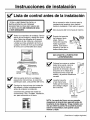
Lista de control antes de la instalacibn
iTODA LA INFORMACION PARA LA
INSTALACION EN LAS PAGINAS
SIGUIENTES ES PARA SER USADA EN
LA INSTALACION DE HORNOS DE UNA
O DOS UNIDADES!
Retire los materiales de embalaje. Revise
detr&s de las bisagras y debajo del fondo
falso. Retire las etiquetas de la puerta,
el pl&stico de las molduras y del panel,
y todas las cintas alrededor del homo, y
cualquier tornillo de envio que sostenga
el horno con la almohadilla de la base.
I -- I
Parrillas del homo
Cacerola y parrilla
ara a ar _ Paquete de
p s instrucclones
Abra la puerta del horno y extraiga el
paquete de instrucciones, la cacerola y
parrilla para asar, y las parrillas del horno.
No es necesario retirar la puerta para la
instalaci6n del producto, pero hacerlo
facilita la instalaci6n. Para retirar la puerta:
Abra la puerta del horno hasta el maximo.
Extraiga las instrucciones de instalaci6n
del paquete y 16alas cuidadosamente
antes de empezar la instalaci6n.
Empuje los topes de
las bisagras hacia
abajo, hacia el
marco de la puerta
hasta la posici6n
abierta. Esto podria
requerir el uso de un
destornillador piano.
Posicibn
, abierta de
I,_,i, la bisagra
Ranur '_
dela ra _
bisag
Brazo de
la blsagra
Cerci6rese de guardar bien todas las
instrucciones, Uso y Cuidado, Instalaci6n,
etc. para referencia en el futuro.
iNO LEVANTE LA PUERTA POR
LA EMPUI_IADURA!
!
Coloque las manos en ambos
lados de la puerta, cierre la
puerta del homo hasta la
posici6n de remoci6n, 6sta se
encuentra en la mitad de la
trayectoria entre el tope del
asador y la posici6n totalmente
cerrada.
Levante la puerta
y hale hacia fuera
hasta que los brazos
de la bisagra salgan
de la ranuras.
Bisa_ ra sale
de la ranura
NOTA: La puerta del homo es muy pesada.
Asegdrese de tenerla bien agarrada antes de
levantarla de las bisagras. Tenga cuidado una
vez que retire la puerta. No acueste la puerta
sobre la empufiadura; esto podria causar
marcas y rayas.
3 (Contin6a en la p&gina siguiente)

Instrucciones de instalacibn
[_ Lista de control antes de la instalacibn
cont.
Coloque el horno sobre la mesa o
plataforma al nivel de la abertura del
corte. (La plataforma debe soportar
150 libras para hornos de una unidad
y 275 libras para hornos de dos
unidades.)
Extraiga la moldura de fondo de la
parte superior del homo. La misma
ser_. instalada al final de la instalaci6n.
La moldura de fondo est,. envuelta por
separado y pegada a la parte superior
de la unidad.
4

Instrucciones de instalacibn
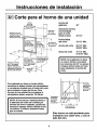
Corte para el horno de una unidad
Ancho Ancho del
del corte gabinete
Permita 11116" de
sobrepaso del homo
sobre los bordes
laterales del corte
21
Permita un mlmmo
de 1" para el
sobrepaso del
Permita un minimo horno pot encima
de 21" de espacio 11/4"por debajo
para las esquinas, I del corte
cajones, paredes, etc., .._
adyacentes cuando las _ Ancho del
puertas estdn abiertas
30"
Ubicacibn
de la caja
de conexi6n
22" hasta el
fondo de la caja
de conexidn
Ubicacibn minima
recomendada para
el corte desde el
Ubicacibn minima
recomendada
para el corte
desde el piso
Profundidad
del corte
Ancho del corte
Altura de corte
30"
32 112"
23 112" Min.
28 112" Min.
28 518" Mdx.
27 1/4" Min.
27 5/16" Mdx.
NOTA: Si el gabinete no tiene
un marco frontal y los lados
son menores de 3/4" en grosor,
coloque ambos lados en linea
para establecer el ancho del
corte.
Si el gabinete no tiene un fondo sblido,
entonces se deben instalar dos abrazaderas
o correderas nivelada con el rondo del corte
para sostener el peso del horno. Para
hornos de una unidad las correderas o
abrazaderas deben soportar 150 libras.
NOTA: Si las marcas, imperfecciones o
la abertura del corte son visibles por
encima del horno instalado, quizds sea
necesario agregar relleno debajo de las
correderas y moldura delantera hasta
que se cubran.
Abrazaderas
de soporte
adecuadas
para las
correderas --
21 5/8"
Linea de centro \
sobre gabinetes
2"x4"o
correderas
equivalentes
niveleada
con el fondo
del corte
Este horno no estd aprobado para
instalarse uno sobre otro, o uno al
lado del otro.
5

Instrucciones de instalacibn
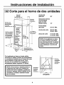
Corte para el horno de dos unidades
Permita 11116"
para sobrepaso
del horno sobre
los bordes
laterales del corte --_.
Permita un minimo
de 21" de espacio
para las esquinas,
cajones, paredes,
etc., adyacentes
cuando las puertas
estdn abiertas
21"
Ancho del Ancho del
gabinete
<_28 1/2" Urn. _,. 5". gabinete
28 518" M_x. --_"
"7
del corte
51 13/16" Mfn,
51 15/16" Max.
'_'_La abertura
entre las
paredes
interiores
debe ser
como minimo
28 1/2" de
ancho
Permita un
minimo de 1"
para el
sobrepaso
del horno J
por encima
y 1_/4por"
debajo _1
Ubicacibn
de la caja
de conexi6n
/
47" hasta el
fondo de la caja
de conexi6n
del corte _- .
_._ _..._ _ ,,_-_ Ubicaci6n minima
An_ recomendada para el
gabinete _---___.._orte,desde el piso 12"
30" _-_
Ubicacibn minima
recomendada
para el corte
desde el piso
Profundidad
del corte
Ancho del corte
Altura de corte
30"
12"
23 112" Min.
28 112" Min.
28 518" Mdx.
51 13/16" Min.
51 15/16" Mdx,
NOTA: Si el gabinete no tiene
un marco frontal y los lados
son menores de 3/4" en grosor,
coloque ambos lados en linea
para establecer el ancho del
corte.
Si el gabinete no tiene un fondo sblido,
entonces se deben instalar dos abrazaderas
o correderas nivelada con el rondo del corte
para sostener el peso del horno. Para
hornos de una unidad las correderas o
abrazaderas deben soportar 275 libras.
NOTA: Si las marcas, imperfecciones o
la abertura del corte son visibles por
encima del homo instalado, quizds sea
necesario agregar relleno debajo de las
correderas y moldura delantera hasta
que se cubran.
Abrazadems
de sopo_e
adecuadas
para las
/ L_nea de centro \
sobre gabinetes
x4"o
correderas
equivalentes
niveleada
con el fondo
del corte
6

Instrucciones de instalacibn
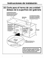
Corte para el horno de una unidad-
debaio de la superficie del gabinete
Las estufas eldctricas o de gas se
pueden instalar sobre este horno.
Consulte las instrucciones de la estufa
para el tama_o del corte. Consulte la
etiqueta encima del homo para los
modelos de estufas aprobados.
Ubicaci6n de la
caja de conexi6n
240V/208V
Las conexiones de gas y eldctricas
para una estufa a gas de 30, deben
estar ubicadas en un lugar adyacente
de facil acceso en el lado derecho.
Para estufas a gas de 36, la conexi6n
se debe realizar a la izquierda.
Material de relleno
para la parte superior
y/o lados podHa
ser necesario si la 1112" M_n.
unidad esta 28 5/8" Max.
entre gabinetes
existentes. Asegdrese I
de que est_ pegado
firmemente ya que 27 114" Mfn.
_ste anclara el homo 27 5116" Max. t
- en el gabinete, j_--_
I
I
_Permita un mfnimo
de 1" para sobrepaso 22" Mfn.
del homo pot encima plataforma
: y 11116"para de soporte
sobrepaso del homo superior
-sobre los bordes
laterales del corte
36"
Altura tipica
del gabinete
I
Plataforma de _
fJ 3/4" de soporte
requerida
DEBE SOPORTAR 150 LIBRAS
5 9/16"
Dimensibn de referencia para la
altura maxima de soporte con una
altura tfpica de estufa de 36"
NOTA: Este horno no estd aprobado
para ser instalado debajo de un estufa
de disco sblido, induccibn o modular
de tiro descendente (downdraft).
7

Instrucciones de instalacibn
Conexiones eldctricas
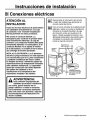
ATENCION AL
INSTALADOR:
Todos los hornos electricos de pared deben
ser cableados directamente en una caja
de conexibn. Una "enchufe-receptaculo"
NO ES permitido en estos productos.
NO acorte el conducto flexible. La
abrazadera para controlar la presibn debe
estar firmemente adherida a la caja de
conexibn y el conductor flexible debe estar
firmemente adherido a la abrazadera. Si el
conducto flexible no se ajusta al interior
de la abrazadera, no instale el horno hasta
que obtenga el tama_o apropiado.
NOTA AL ELECTRICISTA: Los 3 alambres
el_ctricos proporcionados con este aparato
son reconocidos por la UL para conexiones
a cableado residencial de mayor calibre.
El aislante de estos 3 alambres supera las
especificaciones de temperatura indicadas
para cableado residencial. La capacidad
actual de conduccibn del cable depende
del calibre del cableado y de la
clasificacibn de la temperatura del
aislamiento alrededor del alambre.
ADVERTENCIA:
Una conexibn inapropiada del
cableado de aluminio residencial
con cobre, podria resultar en un
peligro electrico o hasta en incendio.
Use solamente conectores dise_ados
para unir cobre con aluminio y siga las
recomendaciones del fabricante con
mucho cuidado.
Desconecte el interrupter del circuito
o retire los fusibles que alimentan el
circuito ramal del horno.
Con el horno enfrente de la abertura del
gabinete, sobre una mesa o plataforma
conecte el conducto flexible a la caja
de conexiSn como se muestra en la
figura. Usted necesitar_, comprar una
abrazadera liberadora de presi6n para
completar la conexi6n del conducto
hacia la caja de conexi6n.
Ubicacion de la
caja de conexibn
Conducto
48 1/2"
de largo
Coloque el homo en
el soporte para ayudar
en la conexion del
conductor
Abrazadera lIberadora
_- de presibn (no incluida)
debe usarse en la caja
de conexi6n
8 (Contint3a en la pagina siguiente)

Instrucciones de instalacibn
Conexiones eldctricas cont.
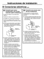
Conexi6n para nueva .
construccion y de circuito
ramal de cuatro conductores
• Cuando se instale en una construcci6n
nueva, o
• Cuando se instale en una casa m6vil, o
• AI instalar en un vehiculo de recreacfon, o
• Cuando los c6digos locales no permitan
hacer conexi6n a tierra a traves de un cable
neutro:
a. Corte la punta del alambre neutro (blanco)
del empalme. Pele la punta del alambre
neutro (blanco) hasta exponer la extensi6n
apropiado del conductor.
Alambres de
conexi6n a tierra
I'_ Cubierta de la caja
"_J de conexibn
b. Conecte el alambre de conex6n a tierra
(verde o cobre descubierto) de acuerdo
a los c6digos locales. Si el conductor de
conexi6n a tierra de la residencia es de
aluminio, consulte la ADVERTENCIA en
la p&gina 8.
c. Conecte el alambre neutro del horno
(blanco) al circuito ramal neutro (blanco o
gris) de acuerdo con los c6digos locales,
usando una tuerca para alambres.
d. Conecte el alambre rojo del horno al
alambre rojo del circuito y el alambre negro
del horno al alambre negro del circuito de
acuerdo con los c6digos locales. Si los
alambres rojos, negros o blancos de la
residencia son conductores de aluminio,
consulte la ADVERTENCIA en la p&gina 8.
e. Instale la cubierta de la caja de conexi6n.
Conexi6n de circuito ramal
de tres conductores
Cuando conecte un circuito ramal de
3 conductores, si los c6digos locales Io
permiten:
a. Conecte el alambre descubierto del horno
con el alambre neutro (blanco) del circuito
ramal (blanco o gris), usando una tuerca
para alambres.
b. Conecte el alambre rojo del horno al
alambre rojo del circuito ramal, usando
una tuerca para alambres.
c. Conecte el alambre negro del horno al
alambre negro del circuito ramal de
acuerdo a los c6digos locales, usando
una tuerca para alambre. Si los alambres
rojos, negros o blancos de la residencia
son conductores de aluminio, consulte la
ADVERTENCIA en la p&gina 8.
d. Instale la cubierta de la caja de conexi6n.
9

Instrucciones de instalacibn
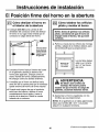
Posicibn firme del horno en la abertura
Cbmo deslizar el horno en
el interior de la abertura
a. Coloque (sin atar) una cuerda de 36"
alrededor del conductor antes de deslizar
el homo en su lugar. Esto evitar_ que el
conducto se caiga detrAs del homo.
\\\_\\\\\\\_\\\\\\\\\\\\\\\\\\\\_\\_\\\\
Tire hacia afuera
per el lazo de la
cuerda mientras
empuja el horno
_< hacia el interior
I
del gabinete
b. Levante el horno hacia el interior del corte
en el gabinete usando la abertura del
homo para agarrarlo. Empuje contra el
marco frontal del homo cuidadosamente.
No empuje contra los bordes externos.
c. A medida que el homo se desliza hacia
atr_.s tire de la cuerda para que el conducto
quede encima del homo de forma natural.
d. Cuando este seguro de que el conducto
est& fuera del camino, deslice el homo
completamente hacia atr&s y hacia el
interior de la abertura. Retire la cuerda
halando de un extremo.
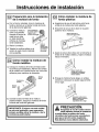
Cbmo taladrar los orificios
piloto y montar el horno
NOTA: Antes de perforar los orificios
piloto, cercibrese de que el horno se
empujb hasta el fondo y de que este
centrado.
a. Perfore a trav_s de los orificios de montaje
(arriba y abajo) de la moldura lateral, para
los tornillos #8 que se proporcionan.
Ubicacibn de J
los orificios
jJ de montaje
Los tornillos deben
estar a un minimo
de 1/4" del frente
del corte.
ADVERTENCIA:
Se deben usar tornillos de
montaje. No hacerlo podria
resultar en que el horno se caiga del
gabinete, causando lesiones serias.
b. Ajuste bien el horno al gabinete con los
tornillos que se proporcionan.
NOTA: Si el gabinete es en tabla aglomerada
debe usar tornillos #8 x 3/4". Los puede
adquirir en cualquier ferreteria.
10 (Contin0a en la pagina siguiente)

Instrucciones de instalacibn
r_ Preparacibn para la instalaci6n
de la moldura de fondo
a. Con el horno instalado, tome la moldura de
fondo y centrela en el borde frontal del fondo
de la abertura del gabinete.
b. Usando la moldura
como una plantilla
marque el centro de
cada ranura (dos
en total) donde los
orificios de montaje
ser&n taladrados.
Con la moldura en
la posici6n inferior
marque los (2)
orificios de montaje
c. Retire la moldura.
d. Taladre los orificios piloto en el
centro de cada marca indicada
Retire la
moldura
inferior antes
de pretaladrar
los orificios
de montaje
con la ptantilla.
r_ cbmo instalar la moldura de
fondo metdlica
a. Coloque la moldura de fondo centrada sobre
los orificios pre-taladrados. Adhiera los bordes
de la motdura en ta parte inferior con una cinta
adhesiva para mantener la alineaci6n.
Tornillo de la
moldura
Moldura
lateral
Moldura
lateral
Moldura inferior
met_ilica
b. Usando los dos tornillos de la moldura
proporcionados, asegure la moldura de fondo
al borde del fondo del gabinete.
I[I MPORTANTE: Si alguna vez esta unidad
se retira del gabinete o para reparacibn,
primero se debe retirar la moldura o de Io
contraio se podria dafiar.
I-€--_cbmo instalar la moldura de
fondo pldstica
a. Aseg_rese de que el lado piano est6 hacia
arriba de la moldura de fondo pl&stica.
b. Encuentre la ranura de la Ilave en la parte
posterior de la moldura.
Ranura de la Ilave y
lado ancho hacia arriba
c. Ajuste la ranura de la Ilave con el remache al
fondo de ta moldura lateral, y baje la moldura
hacia el remache.
el extremo de la moldura
inferior met_ilica
d. Empuje la moldura hacia abajo, en ambos
extremos, hasta que se ajuste seguramente
en su lugar.
Empuje la moldura hacia
aba|o, en ambos extremos_
hasta que se ajuste
seguramente en su lugar
PRECAUCION:
Asegdrese de no dar vuelta al horno
hacia adelante durante la instalacibn
o podria dafiar la moldura de fondo.
La moldura de fondo provee una abertura
para que el aire frio entre al gabinete.
Esta abertura nunca deberia obstruirse.
11

Instrucciones de instalacibn
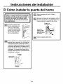
I-D-1Cbmo instalar la puerta del horno
NOTA: La puerta del horno es pesada.
Quizds necesite ayuda para levantar y
deslizar la puerta hacia abajo sobre
las bisagras. No levante la puerta por
la empu_adura.
['_ Levante la puerta del
horno colocando una
mano en cada lado.
La puerta es pesada y
quizas necesite ayuda.
No levante la puerta
por la empufiadura.
[-D---_Con la puerta en el mismo angulo que la
posici6n para remoci6n (en la mitad de
la trayectoria entre el tope del asador y
la posici6n totalmente cerrada), coloque
la muesca del brazo de la bisagra en el
interior del borde inferior de la ranura de
la bisagra. La muesca del brazo de la
bisagra debe apoyarse completamente
al fondo de la ranura.
Brazo de
la bisagra
Borde inferior ! _.__
de la ranura J
Muesca de
la bisagra
r-_ Abra la puerta del homo hasta el
maxlmo.
['0--"_ Empuje los topes de las bisagras contra
el marco frontal de la cavidad del homo,
hasta alcanzar la posici6n de cierre.
Bisagra en la
posici6n de cierre
Muesca de la
bisagra ajustada
firmemente en el
de la bisagra
[D--'_ Cierre la puerta del horno.
12

Instrucciones de instalacibn
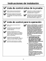
Lista de control antes de la prueba
Retire cualquier cinta de protecci6n y
etiqueta que todavia este presente.
[_ Revise para asegurarse de que todos
los alambres est_n bien conectados y
no aplastados o en contacto con partes
m6viles.
Inspeccione la moldura de fondo para
cerciorarse de que est& instalada
apropiadamente (ver p&gina 11).
Inspeccione para cerciorarse de que los
tornillos de montura estan instalados y
apretados hasta quedar al mismo nivel
de la moldura lateral (ver p&gina 10).
Lista de control para la operacibn
[_ Retire cualquier articulo del interior [_
del horno.
Cerci6rese de que el conducto est_
conectado firmemente a la caja de
conexi6n el6ctrica.
Conecte la energia hacia el horno.
(Consulte su Manual de Uso y Cuidado.)
Verifique que las unidades de horneado y
asado, y todas las funciones de cocci6n
operan correctamente.
Cerci6rese de que el interruptor de
circuito no se haya disparado o de que los
fusibles de ta casa no esten quemados.
Consulte el manual de Uso y Cuidado
para una lista de problemas eventuales.
NOTA AL ELECTRICISTA: Los alambres
eldctricos proporcionados con este
aparato son reconocidos por la UL para
conexiones cableado residencial de
mayor calibre. El aislante de estos
alambres supera las especificaciones
indicadas para cableado residencial.
La capacidad actual de conducci6n del
cable depende de la clasificaci6n de la
temperatura del aislamiento alrededor
del alambre.
NOTA: CABLEADO DE ALUMINIO
A ADVERTENCIA:
UNA CONEXlON INAPROPIADA
DEL CABLEADO DEL ALUMINIO
RESIDENCIAL CON EL COBRE,
PODR[A RESULTAR EN PROBLEMAS
SERIOS O EN INCENDIO.
S. Conecte los alambres de cobre a
los alambres de aluminio usando
conectores especiales disefiados
y aprobados por UL para unir cobre
y aluminio y siga cuidadosamente
el procedimiento para hacer las
conexiones recomendadas por el
fabricante.
NOTA: El alambrado que se use,
la ubicacibn y el tipo de conexibn,
etc., deben cumplir con las buenas
prdcticas de alambrado y los
cbdigos locales.
13

NOTAS
14
-
 1
1
-
 2
2
-
 3
3
-
 4
4
-
 5
5
-
 6
6
-
 7
7
-
 8
8
-
 9
9
-
 10
10
-
 11
11
-
 12
12
-
 13
13
-
 14
14
-
 15
15
-
 16
16
-
 17
17
-
 18
18
-
 19
19
-
 20
20
-
 21
21
-
 22
22
-
 23
23
-
 24
24
-
 25
25
-
 26
26
-
 27
27
-
 28
28


Kenmore 911.47712 Guía de instalación
- Categoría
- Hornos
- Tipo
- Guía de instalación
en otros idiomas
- English: Kenmore 911.47712 Installation guide
Otros documentos
-
GE PT920DR2BB Guía de instalación
-
GE JK1000DF1BB Installation Instructions Manual
-
GE CT9800SH3SS Guía de instalación
-
GE ZEK958SFSS Manual de usuario
-
-
GE Profile PT925DNBB Guía de instalación
-
GE Profile PT925SNSS Guía de instalación
-
 Kenmore Elite 79048913411 Guía de instalación
-
Frigidaire FEB374CHBA Guía de instalación
-
Frigidaire FEB398CETB Guía de instalación
