GE JK1000DF1BB Installation Instructions Manual
- Tipo
- Installation Instructions Manual

Installation Instructions
27" & 30" Electric Built-in Wall Ovens
Questions? Calt 1.800.GE.CARES(1.800.432.2737) or visit www.GEAppiiances.com
In Canada, calt 1.800.561.3344 or visit www.GEAppliances.ca
BEFORE YOU BEGIN
Reed these instructions completelg end
cerefullg.
" IMPORTANT -- Save these instructions
for local inspector's use.
" IMPORTANT -- Observe allgoverning
codes and ordinances.
, Note to Installer- Besure to leave these
instructions with Consumer.
, Note to Consumer- Keepthese instructions
for future reference.
, Skill level- Installation of this appliance
requires a qualified installer or electrician.
. Proper installation is the responsibility
of the installer.
, Product failure due to improper installation
isnot covered under Warranty.
, Product is for indoor use onlg.
ATTENTION INSTALLER: All electric wall ovens must be hard-wired (direct-wired)into an
approved junction box. A plug and receptacle is NOT permitted on these products.
FOR YOUR SAFETY:
WAR NING:Before beginning the installation, switch power off at the service panel and
lock the service disconnecting means to prevent power from being switched on accidentallg. When the
service disconnecting means cannot be locked, securelg fasten a prominent warning device, such as a tag,
to the service panel.
Besure the oven is securelg installed in a cabinet that is firmlg attached to the house structure.
Weight on the oven door could cause the oven to tip and result in injurg. Neverallow angone to climb, sit,
stand or hang on the oven door.
Make sure the wall coverings, counters and cabinets around the oven can withstand the heat
(up to 200°F [93.3°C])generated bg the oven.
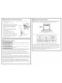
MATERIALS YOU MAY NEED
JunctionBox
Wire Nuts
Strain ReliefClamp for 1/2" Conduit
TOOLS YOU MAY NEED
1/8" Drill Bit and Electric or Hand Drill
PhillipsScrewdriver
Wire Strippers
DESIGN INFORMATION
SINGLEOVENINSTALLATIONS
The single oven mag be installed in a cabinet alone or above a warming drawer. Thesingle oven meg also
be installed below a countertop or below specified cooktops. See the label on top of the oven for approved
models.
DOUBLEOVENINSTALLATIONS
Adouble oven mag beinstalled in a cabinet alone or above a warming drawer. Seethe label on top of the
oven for approved models.
IMPORTANT:Alwagsreferto individualinstallationinstructionspackedwitheachproductforspecific
requirements.
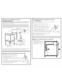
I_] PREPARE THE OPENING
NOTE: If the cabinet does not have a solid bottom, two
braces or runners must be installed to support the weight
of the oven. For single ovens, the runners and braces
must support 200 Ibs 191kg). For double ovens, the
runners and braces must support 375 Ibs. 1170 kg).
NOTE: If marks, blemishes or the cutout opening are
visible above the installed oven, it mag be necessarg to
add wood shims under the runners and front trim until
the marks or opening are covered.
NOTE: If the cabinet does not have a front frame and
the sides are less than sA"11.9cm) thick, shim both sides
equallg to establish the cutout width.
2" x 4"(5 cm x 10 cm)
or Equivalent Runners Level
with Bottom of Cutout
and Flush with Sides of Cutout
Suitable
Bracing
to Support.
m
Ill REMOVE PACKAGING MATERIALS
Failure to remove packaging materials could result in damage to the appliance. Remove all packing
parts from oven, racks and heating elements. Remove protective film and labels on the outer door
and control panel. Also, remove plastic on trims and panel, all tape around the oven and ang shipping
screws securing the oven to the base pad. Open oven door and remove literature pack and oven
racks. Remove the bottom trim from the top of the oven. It will be installed at the end of the installation
process. The trim is wrapped separatelg and taped to the top of the unit. Remove pedestal rails from
separate box and set aside (30" Double Wall Ovens Onlg).

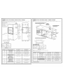
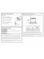
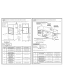
r_==_ CUTOUT FOR SINGLE OVENS IN WALL CABINET
NOTE: If the cabinet does not have a front frame and the sides are less than sA" (1.9 cm) thick, shim
both sides equally to establish the cutout width.
These ovens
are not
approved for
stackable
installations.
Opening
Between Inside
Wails Must be
at Least 28-1/2"
(724 cm) Wide
H
Sideby-SideInstallations
Installtwo ovensin separatecutouts
CenterLine CenterLine
] so.s"177scrnl ]
I 30"models I
] 2T' (68.58crn) ]
I 27"modes !
I !
--I
Cutout- Cutout -
observeall observeall
dimensionsand dimensionsand
requirements requirements
"---_1 I_== 2"Is1cm/r_in
Junction
Box
Location
(junction
box may
Jbe located
in adjacent
cabinetl
: --T
22" (559 __-=_lm
cm} Hin. to
_ Bottomof
J Junction
J BOX
J
..... ~%:;, ....
-" " Cutou/Depth
(59.7cm}Nlin.
Note: Allow
1/4" (0.64 cm)
clearances
from side
edges of oven
door.
_____B___-_
t
F
G
............................... L ......
t
C
m
4_
Recommended
Cutout Location
from Floor
32 1/2" (826cm)
A---d
Dimension Dimension Description 27" Single Oven 30" Single Oven
A Cabinet Width 27" (68.6 cm) 30" (76.2 cm)
B Cutout Width 25" (63.5 cm) min. 28½" (72.4 cm) min.
25½" (64.1 cm) max. 28sA " (72.7 cm) max.
C Cutout Height 27%" (70.2 cm) min. 27½" (69.2 cm) min.
28½" (71.4 cm) max. 27s4d ' (69.4 cm) max.
D Overlap of Oven Over 1" (2.5 cm) _¼_d'(1.75 cm)
Side Edges of Cutout
E Clearance to 23" 150.8 cm) min. 23" 153.3 cm) min.
Adjacent Corners,
Drawers, Walls, etc.,
When Door Is Open
F Overlap of Oven 1" 12.5 cm) min. 1" 12.5 cm) min.
Top of Cutout (11/4'' 13.2 cm) for PT9050)
G Overlap of Oven 1" (2.5 cm) min. 1½" (3.2 cm)
Bottom of Cutout
H Junction Box Location 8¾" (22.2 cm) max. 9½" (24.1 cm) max.
right side only right side only
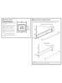
CUTOUT FOR SINGLE OVENS - UNDER COUNTER
NOTE: These ovens are only approved to be installed under the specific models as labeled on the unit.
Gas or Electric Cooktops May Be Installed Over This Oven.
See Cooktop Installation instructions for Cutout Size, 240V/208V
See Label on Top of Oven for Approved Models. Junction Box
Location (junction
box may be
in adjacent cabinet)
25" (63.5 cm)
Gas and Electrical Connections
for Gas Cooktop Must be Located
in an Adjacent Accessible
Location to the Right
MUST SUPPORT 200 Ibs. (60 kg) FOR SINGLE OVENS
MUST SUPPORT 375 Ibs. (170 kg) FOR DOUBLE OVENS
Side-by-Side Installations
Install two ovens in separate cutouts.
center Line CenterLine
I 30.5"(775cm)30" models
36" (91.4 cm)
Countertop
Height
Cutout - observe
all dimensions and
requirements.
__q
JL
Cutout = observe
all dimensions and
requirements.
_=2" (5.l cm)Nlin.
NOTE:One cooktop may be centered over either oven in
the side-by-side installation.
Dimension Dimension Description 27" Single Oven 30" Single Oven
A Cabinet Width 25" (63.5 cm) min. 28½" (72.4 cm) min.
25¼" (64.1 cm) max. 28%" (72.7 cm) max.
B Cutout Height 27%" (70.2 cm) min. 27½" (69.2 cm) min.
28½" (71.4 cm) max. 27%d' (69.4 cm) max.
C Unit Overlap Top 1" (2.5 cm) 1" (2.5 cm)
(1VJ' (5.2 cm) for PT9050)
D Unit Overlap Bottom 1" (2.5 cm) l_/J ' (5.2 cm)
E Unit Overlap Side Edges 1" (2.5 cm) _¼_d'(1.75 cm)
F Junction Box Location 8sA" (22.2 cm) max. 9½" (24.1 cm) max.
right side only right side only
Continue to Section 4.

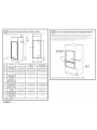
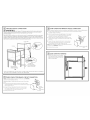
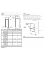
CUTOUT FOR DOUBLE OVENS (2THERMAL OVENS)
NOTE: If the cabinet does not have a front frame and the sides are less than sA"(1.9 cm)
both sides equall_h.i
Junction
BO×
Location
(junction
/ boxmay
/be located
in adjacent
cabinet)
l
J
O _
t
F
G
t
hick, shim
i
r
%
r
i
Dim. Description 27" Double Oven 30" Double Oven with 30" Double Oven
Pedestal without Pedestal
A Cabinet Width 27" (68.6 am) 30" (76.2 am) 30" (76.2 am)
B Cutout Width 25" (63.5 cm) min. 28½" (72.4 cm) min. 28½" (72.4 cm) min.
25¼" (64.1cm) max. 28%" (72.7 cm) max. 28%" (72.7 cm) max.
C Cutout Height 4%_d' (126.2cm) min. 5113/S' (131.6 cm) min. 50 ¼" (127.64cm)
50½" (127.5am) max. 51_/_d' (151.9 am) max.
D Overlap of Oven 1" (2.5am) _½d'(1.75 am) _4d' (1.75 am)
Over Side Edges
of Cutout
E Clearanceto 23" (50.8 cm) min. 23" (53.3 cm) min. 23" (53.3 cm) min.
Adjacent Corners,
Drawers, Walls, etc.,
When Door/sOpen _ ,
F Overlap of Oven 1" (2.5 am) rain. 1" (2.5 cm) min. 1" (2.5 cm) min.
Top of Cutout (1¼"(5.2cm) for PT9550) (1¼"(5.2cm) for PT9550)
G Overlap of Oven 1"(2.5 cm) min. 11/4"(5.2 cm) 11/4"(5.2 cm)
Bottom of Cutout
H Junction Box 8sA" (22.2 cm) max. 9½" (24.1 cm) max. 9½" (24.1 cm) max.
Locat!on _ rights!de only _ rights!de only . rights!de only
J Height to Bottom 44" (111.8cm) 47" (i19.4cm) 47" (i19.4cm)
of Junction Box
K Recommended 15¼" (55.7 am) 12" (50.5 am) 12" (50.5 am)
Cutout Location
from Floor
Continue to Section 3.
J31-i0856-iJo -isGE
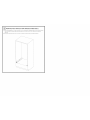
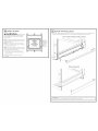
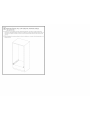
CUTOUT FOR INSTALLATION OVER A WARMING DRAWER
NOTE: Installtheoven onlywithspecificmodels listedon the labellocatedon topofthe oven.
NOTE: Additionalclearancesbetween cutoutsmay be required.Checktobe suretheoven supports
above theWorming Drawer locationdo notobstructtherequiredinteriordepthand height.
When installinga Worming Drawer belowa singleordoubleoven,a separate120V,60 HZ,properly
grounded receptaclemustbe installed.Referto installationinstructionspocked with
theWorming Drawer forspecificinstallationrequirements.
Anti-Tip Block Against
Rear Wall Per Warming
Drawer Requirement
2" (5.1 cm)
Min.
Per Warming
Drawer
Requirement
Continue to Section 3 for DWO with Pedestal. Otherwise, continue to Section 4.

_-I PEDESTAL RAIL INSTALLATION (DOUBLE OVENS ONLY)
A. Place one pedestal rail on each cabinet runner or centered on opposite side of solid cabinet bottom
flush with side of cabinet opening. Locate each rail so that front of rail is behind front cabinet
opening.
B. Drill pilot holes and attach rails to runner or bottom of cabinet with provided hardware.

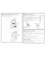
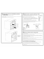
[_ DOOR REMOVAL {RECOMMENDED)
NOTE: Door removal is not a requirement for installation of the product but is an added convenience.
To remove the door:
A. Open the oven door as far as it will go.
B. Push both hinge locks down toward the door frame
to the unlocked position. This may require a flat-
blade screwdriver. DO NOT LIFTTHE DOOR BYTHE
HANDLE!
C. Place hands on both sides of the door and close the
oven door to the removal position (approximately
1"-2" [2.5 cm-5.1 cm] from the closed position).
D. Lift the door up and out until the hinge arms clear
the slots.
NOTE: The oven door is very heavy. Be sure
you have a firm grip before lifting the oven door off
the hinges. Use caution once the door is removed. Do
not lay the door on its handle.
This could cause dents or scratches.
Hinge
_1_ Unlocked
Position
Hinge Slot ,
Hinge Arm
Hinge Clears
Slot
r_ ELECTRICAL REQUIREMENTS
A WARNING: This appliance rnust be properly grounded
A WAR N I N G: To prevent fire or shock, do not use an extension cord with this appliance.
A WA R N I N G: To prevent shock, remove house fuse or open circuit breaker before
beginning installation.
A WAR N IN G: ,mproperconnectionofa,uminumhousewiring to copper leads can result
in an electrical hazard or fire. Useonly connectors designed for joining copper to aluminum and follow the
manufacturer's recommended procedure closely.
We recommend you have the electrical wiring and hookup of your appliance connected by a qualified
electrician. After installation, have the electrician show you how to disconnect power from the appliance.
You must use a single-phase, 120/208 VACor 120/240 VAC,60 Hertz electrical system. Ifyou connect to
aluminum wiring, properly installed connectors approved for use with aluminum wiring must be used.
Effective Januarg 1, 1996,the National Electrical Code requires that new construction (not existing) utilize
a four-conductor connection to an electric oven. When installing an electric oven in new construction,
a mobile home, recreational vehicle or an area where local codes prohibit grounding through the
neutral conductor, refer to the section on four-conductor branch circuit connections.
Check with your local utilities for electrical codes which apply in your area. Failure to wire your oven
according to governing codes could result in a hazardous condition. If there are no local codes, your
oven must be wired and fused to meet the National Electrical Code, NFPA No. 70 i latest edition,
available from the National Fire Protection Association.
[_] ELECTRICAL REQUIREMENTS {CONT.)
Thisappliance must be supplied with the proper voltage and frequency and connected to an individual,
properly grounded branch circuit, protected by a circuit breaker or fuse. See the rating plate located on the
oven frame to determine the rating of the product•
Rating Plata
Location ....................................;
_================_ _
Rating plate is located on the oven side trim.
Use the chart below to determine the minimum recommended dedicated circuit protection:
Recommended
KW Rating KW Rating Circuit Size
240V 208V {Dedicated)
<4.8 KW <4.2 KW 20 Amp
4.9 KW=7.2 KW 4.2 KW=6.2 KW 30 Amp
7.3 KW-9.6 KW 6.3 KW-8.3 KW 40 Amp
9.7 KW-12.0 KW 8.4 KW-10.4 KW 50 Amp
DO NOTshorten the flexible conduit. The conduit strain relief clamp must be securely attached to the
junction box and the flexible conduit must be securely attached to the clamp. If the flexible conduit will not
fit within the clamp, do not install the oven until a clamp of the proper size isobtained•
The 3 power leads supplied with this appliance are suitable for connection to heavier gauge household
wiring. The insulation of these 3 leads israted for temperatures much higher than the temperature rating
of the household wiring. Thecurrent-carrying capacity of the conductor is governed by the wire gauge and
the temperature rating of the insulation around the wire.

MAKE ELECTRICAL CONNECTIONS
A WA RNING:Sw,tchpower off at the service panel and lock the service disconnecting
means to prevent power from being switched on accidentallg When the service disconnecting means
cannot be locked, securelUfasten a prominent warning device, such asa tag,
to the service panel.
Place oven on table or platform even with the cutout opening. For a single oven, the platform must support
200 Ibs.(9! kg);and for a double oven, the platform must support 375 Ibs.(170 kg).Connect the flexible
conduit to the electrical junction box as shown below*. Position the conduit in such a manner that it will lie
behind the unit in a natural loop when the oven is installed. Youwill need to purchase an appropriate strain
relief clamp to complete the connection of the conduit to thejunction box.
Junction Box
Conduit
Place Oven on a
Support to Assist in
Connecting Conduit
Strain ReliefClamp
(not included) Must Be
Used at Junction Box
*Ovens come equipped with a 40" long conduit. If a longer conduit is desired, there mag beone available for
gour model. To check availabilitg or order parts, call !.800.GE.CARES.
[!] THREE-CONDUCTOR BRANCH CIRCUIT CONNECTION
NOTE: If residence leads are aluminum conductors, see WARNING
in Section 5, Electrical Requirements.
When connecting to a three-conductor branch circuit, if local codes
permit:
A. Connect the bare oven ground conductor with the crimped
neutral (white)lead to the branch circuit neutral (white or grag in
color), using a wire nut.
B.Connect the oven red lead to the branch circuit red lead
and the oven black lead to the branch circuit black lead
in accordance with local codes, using wire nuts.
C. Install junction box cover.
_l__un d
Neutral
L _" Wires
"-.J "_ Junction Box
Cover
181 FOUR-CONDUCTOR BRANCH CIRCUIT CONNECTION
NOTE: If residence leads are aluminum conductors, see WARNING in Section 5, Electrical Requirements.
A. Cut the neutral (white) lead from the crimp. Re-strip the neutral (white) lead to expose
the proper length of conductor.
B.Attach the appliance grounding lead (green or bare copper)
in accordance with local codes. If the residence grounding
conductor is aluminum, see WARNING in Section 5.
C.Connect the oven neutral (white) lead to the branch circuit
neutral (white or grog)in accordance with local codes, using
a wire nut.
D. Connect the oven red lead to the branch circuit red lead
and the oven block lead to the branch circuit block lead
in accordance with local codes, using wire nuts.
NOTE: If the residence red, block or white leads ore aluminum
conductors, see WARNING in Section 5.
E.Install junction box cover.
'%r°e nd
unction Box
Cover
[=_SLIDE OVEN INTO OPENING
oLift oven into cabinet cutout using the
oven opening as a grip. Carefullg push
against oven front frame. Do not push
against outside edges.

r_ MOUNT THE OVEN
AWAR NING: Hount,ngscrews
must be used. Failure to do so could result in
the oven failing out of the cabinet, causing
serious injurg.
NOTE: During oven mounting step, ensure that no
damage is done to oven gasket which lines the
edge of oven cavitg.
NOTE: Before drilling the pilot holes, make sure
the oven is pushed as far back into the opening
as it will go and is centered.
NOTE: If the cabinet is particle board, gou must
use #8 × sA"particle board screws. These mag be
purchased at ang hardware store.
A. Drill through the mounting holes (top and
bottom) of the side trim for the #8 mounting
screws provided.
B.Secure the oven cabinet with the screws
provided.
Mounting
Hole
Locations
(hole locations
may vary)
The Screws
Must Bea
Minimum of
1/4" (6 mm)
From the
Front of
the Cutout.
_ BOTTOM TRIM INSTALLATION
. With oven installed, attach the bottom trim through its mounting holes in front vertical brace using
two trim screws provided. Bottom trim lip must be placed under flange of bottom air duct.
SWO's and DWO installations without pedestal
DWO's with pedestals
IMPORTANT: If this unit is ever removed from the cabinet or the oven is ever pulled out for service, |
i
the bottom trim must be removed first or damage to the trim will occur.
1

_OVEN RACK GUIDE INSTALLATION (IF APPLICABLE)
A. Locate included oven rack guide mouting hardware.
B. Placeoven rack guides on cavity wall studs with L bracket towards back of cavity as shown.
¢. Install guides using the 8 provided mounting nuts.
Oven rack
guide shown
in place.
_ REPLACING THE OVEN DOOR
NOTE:The oven door is heavy. You may need help lifting the door high enough
to slide it into the hinge slots. Do not lift the door by the handle.
A. Lift the oven door by grasping each side.
B.With the door at the same angle os the removal position (approximately
1"-2" [2.5 cm-5.1 cm] from the closed position), seat the notch of the hinge
arm into the bottom edge of the hinge slot. The notch of the hinge arm must
be fully seated into the bottom of the slot.
C. Fully open the door. If the door will not fully open. the indentation is not
seated correctly in the bottom edge of the slot.
D. Push the hinge locks up against the front frame of the oven cavity.
to the locked position.
E.Close the oven door.
Hinge in
Locked
Position
J
Notch of Hinge
Securely Fitted Int(
Bottom of Hinge
Slot
Bottom
Edge of
Slot X
! Hinge
J Arm
Hinge Notch
_4-] FINAL INSTALLATION CHECKLIST
, Check to make sure the circuit breaker is closed (RESET)or the circuit fuses ore replaced.
, Besure power is in service to the building.
, Check that oil packing material and tape have been removed. Failure to remove these materials
could result in damage to the appliance once the appliance has been turned on and surfaces have
heated.
, Remove oil items from inside the oven.
, Check to be sure that the mounting screws ore installed and flush with the side trim
(seeSection 10).
, Check that the bottom trim is installed properly (seeSection 11).
, Ensure that air duct opening at bottom of unit is free of obstructions.
, Check that oven rack guides (ifapplicable) ore installed correctly and oven racks function smoothly.
OPERATION CHECKLIST
,Turn on the power to the oven (refer to your Owner's Manual). Verify that the bake and broil units
and oil cooking functions operate properly.
, See your Owner's Manual for the troubleshooting list.
, Besure all of the oven controls ore OFF before leaving the oven.

Instruccionesde instalaci6n
Hornosdeparedel ctricosempotradosde27"y30"
_Preguntas? Llame al 1.800.GE.CARES(1.800.432.2737) o visite GEApptiances.com
EnCanad6, liame al 1.800.561.3344 o visite www.GEAppliances.ca.
ANTES DE COMENZAR
Lea estas instrucdones par completo g con
detenimiento.
" IMPORTANTE- Guardeestasinstrucciones
paraelusadeinspectoreslocales.
° IMPORTANT - Cumplacontodoslosc6digos
gordenanzasvigentes.
• Noteal instalador- AsegOresede@jarestas
instruccionescon elConsumidor.
, Note el consumidor - Conserve estas
instrucciones pare referenda futura.
, Nivel de destreze - La instalad6n de este
aparato requiere un instalador o electridsta
califieados.
, Elinstalador tiene la responsabilidad de
efectuar una instalad6n adecuada.
, La garant[a no cubre las fallas del producto
provocadas par una instalaci6n incorrecta.
, Esteproducto s6lo sedebe user en 6reas
interiores.
ATENCI6NINSTALADOR:T0d0s10shorn0sdeporedel&ctric0sdebenc0ntarconcabiead0dec0nexBnpermanente
(cablead0direct0)dentr0deunacajadec0nexi0nesapr0badaEnestospr0ductosNOsepermiteiac0nexi6ndeltipo'enchufeyreceptacul0"
PARA SU SEGURIDAD:
A ADVERTENCIA:Antesdecomenzar la instalaci6n,desconecte,aenergia
del panelde servicio gbloqueelos mediosde desconexi6npara evitar el accionamiento delaenergia de manera
accidental. Cuandolos mealiesde desconexi6ndeservicionopueden bloquearse,coloquesobre
el panelde servicioun dispositivode advertencia bienvisible,come una etiqueta.
Elhomo debe instalarsebienen un gabinete que se encuentrefirmemente sujeto aiaestructura de ia casa.Sise
coloca pesosobre la puerta del homo, @stepuedevolcarse gprovocar lesiones.Nunca permita que nadiesesuba,
siente,pare ocuelgue de la puerta del homo.
Verifiquequeel revestimientode lasparedes,mostradoresg gabinetes ubicadosalrededordel homo puedan
soportar elcalor (haste 200°F[%,3°C])generado per el homo.
MATERIALESQUEPUEDENECESITAR
Cajadeconexiones
Taponesdealambre
Abrazaderade aliviodetensi6nparaconductode1/2"
HERRAMIENTAS NECESARIAS
Broca de perforadora de 1/8" g perforadora
el@ctricao de mane
Destornillador de estrella
Alicates pelacables
INFORMACI6N DE DISE--O
INSTALACIONESDEHORNOUNICO
El homo 0nice puede instalarse solo en un gabinete o sobre un caj6n calentador. Elhomo 0nice tambi_n
puede instalarse debajo de un mostrador de encimera o debajo de las estufas especificadas. Vea la
etiqueta de la parte superior del homo pare consulter los modelos aprobados.
INSTALACIONESDEHORNODOBLE
Puede instalarse un homo doble solo en un gabinete o sobre un caj6n calentador. Vea laetiqueta de la
parte superior del homo pare consulter los modelos aprobados.
IMPORTANTE:Siempreconsultelosinstruccionesdeinstalacionesindividualesenviadasconcede producto
parerequerimientosespecificos.
[2_ PREPARE LA ABERTURA
NOTA: Siel gabinete no cuenta con un fondo s61ido,
deben instalarse dos abrazaderas o gufas pare
soportar el peso del horno. Para hornos Onieos,las
gufas o abrazaderas deben soportar 200 Ibs (91 kgs).
Para hornos dobles, las gufas o abrazaderas deben
soportar S7SIbs (170 kgs).
NOTA: Simarcas, imperfecdones o la abertura
resultaran visibles sabre el homo instalado, puede
ser necesario agregar cutlas de madera bajo las
gufas g el reborde frontal hasta cubdr las mareas
o la abertura.
NOTA: Siel gabinete no cuenta con un armaz6n
frontal g los lades son menores a un grosor de sA"
(1,9cm), coloque cu_as uniformemente sobre ambos
lades para establecer al ancho de la abertura.
Abrazaderas
adecuadas
pare sostener
las gules
Guias de 2"x 4" (5 cm x !0 cm)
o equivaJentes a nivel con
el fondo del recorte
y niveladas
costados de Rabertura
r_ QUITE LOS NIATERIALES DE EMPAQUE
No quitar los matefiaJes de empaque puede provocar daf_osal electrodom6stico. Quite todas las partes de
empaque del homo, bandejas g elementos decalentamiento. Quite la peliculaprotectora g las etiquetas de
la puerta exterior g panel de control. Tambi6n, quite los elementos pl6sticos de los rebordes g panel, toda la
cinta que cubre el homo g lostornillos de envio que fijan el homo ala almohadilla base.Abra la puerta del
homo g quite elmaterial informative g las bendejas delhomo. Quiteel reborde inferior de la parte superior del
homo. Secolocar6 al final del proceso de instalaci6n. Elreborde se encuentra envuelto en forma separeda g
edherido en la parte superior de la unided. Retirelosdelesdet pedestal de Iacaja que est6 aparte g d_jetosa
un costado (Hornoscon Pared DoNe de30° 0nicamente).

| ABERTURAPARAHORNOSUNICOSENUNGABIENTEDEPARED
NOTA: Si el gabinete no cuenta con un armaz6n frontal g loslados son menores a un grosor de 3/4" (1,9
cm),coloque cuBas uniformemente sobre ambos lados para establecer al ancho de la abertura.
Estos hornos
no est6n
aprobodos
pare
instalaciones
apilables.
La abertura
entre las paredes
nternas debe set
Linea central Linea central
305" (77,5 cm) I
k modelo 50"
i 27"(6858 cm} _1
i modeb 27" !
Abertura - cumpla Abertura - cum@a
con todas Cas _ con todas las
dimensi°nes g l dimensi°nes g
requenm_entos J requenmrentos
""_ _"_"_ 2" (5,1 cm) rain.
Ubicanci6n
de Cacaja de
conexiones
(la caja de
conexiones
puede hallarse
en un gabinete
adgancente)
_2" (55,9cm} U_*'''_
"nfn.hasta Ca
parte inferior
de la caja de
onexiones
4_ _abertura 23 1/2"
_--_-.L_ (59,7 cm} minimo
Nora: Deje
1/4" (064 cm.}
de espaeio
desde los
extremos
lateraCes de
la puerta del
homo.
,,_=......_ B =======,_
t
F
G
t
C
w
Ubicanci6n
recomendada
de (a abertura
desde el piso
52d/2" (82.6 cm}
1_2
Dimensi6n Descripci6ndela dimensi6n Homo _nico de 27" Horno _nico de 30"
A Ancho del gebinete 27" (68,6 cm) 30" (76,2 cm)
B Ancho de le eberture 25" (63,5 cm) mfn. 28½" (72,4 cm) mh.
25½" (64,1 cm) m6x. 28sA" (72,7 cm) m6x.
C Altura de la abertura 27%" (70,2 cm) mfn. 27½" (69,2 cm) mfn.
28½" (71,4 cm) m6x. 27s4d' (69,4 cm) m6x.
D Superposici6n del homo 1" (2,5 cm) _¼_d'(1,75 cm)
sobre los costedos
laterales de la abertura
E Espacio respecto 23" (50,8 cm) min. 23" (53,3 cm) min.
de esquinas adyacentes,
cajones, paredes, etc.,
cuando la puerta
est_ abierta
F Superposici6n de la 1"(2,5 cm) mfn. 1" (2,5 cm) mfn.
parte superior del homo (1½" (3.2 cm) para PT9050)
de la abertura
G Superposici6n de la r' (2,5 cm) m[n. 11/4" (3,2cm)
perte inferior del homo
de la eberture
H Ubicaci6n de la caja 8¾" (22,2 cm) m6×. 9½" 124,1cm) m6×.
de cone×iones s61o lado derecho s61olado derecho
ABERTURAPARAHORNOSUNICOS- BAJOELMOSTRADORDEENCIMERA
NOTA: Estos homos s61opueden instalarse bajo los modelos especificos como se (ndica en la etiqueta
de la unidad.
Pueden Instalarse estufas a gas o el_ctricas sobre este homo.
Ver las instrucciones de instalaci6n de la estufa para el
tama_o de la aberlura.
Ver la etiqueta de la parle superior del homo para Ublcaci6n de la caja
modelos aprobados, de conexiones de
240V/208V
(la caja de conexiones
puede hallarse en un
gabinete adyacente)
25 '* (63,5 cm) F
Las conexiones de gas
y el_ctricas para estufas
a gas deben ubicarse en
una ubicaci6n adyaoente
accesible sobre la derecha.
Dr:BE PODER SOSTENER 200 LBS. (90 kg) PARA HORNOS 0NICOS
DEBE PODER SOSTFNER 375 LBS. (170 kg) PARA PIORNOS DOBLES
Instalaciones lado a lado
Instale dos hornos en aberturas separadas.
Linea central Linea central
30,5" (77,5 cm) modelo 30" I
2T' (68.58 cm) modelo 2T' I
i
|
i-
Abertura - cum@a j Abertura -cumpla
con todas las l con todas las
dimensiones g dimensiones g
requedmientos, requedmientos.
----_1 _ z' 15,icmlMin
NOTA: Una estufa puede centrarse sobre cualquier
homo en la instalaci6n de lado a lado.
22" (55,9 ore) rain. 36 *' (9t,4 cm)
sobre la plataforma Altura del mostrador
de encimera
4" (10,2 cm)
-_ Placa de protecci6n
Dimensi6n Descripci6ndela dimensi6n Horno 6nico de 27" Horno 6nico de 30"
A Ancho del gebinete 25" (63,5 cm) mfn. 28½" (72,4 cm) mfn.
25¼" (64,1 cm) m6x. 28%" (72,7 cm) m6x.
B Alture de le eberture 27%" (70,2 cm) mfn. 27½" (69,2 cm) mfn.
28½" (71,4 cm) m6x. 27s_d' (69,4 cm) m6x.
C Superposici6n de le 1" (2,5 cm) 1" (2,5cm)
unided en perte superior (1½"(3.2 cm) para PT9050)
D Superposici6n de le 1" (2,5 cm) 1VJ' (3,2cm)
unided en perte inferior
E Superposici6n de le r' (2,5 cm) _¼_d'(1,75 cm)
unidadencostadoslaterales
F Ubiceci6n de le ceje 8sA" (22,2 cm) m6x. 9½" (24,1 cm) m6x.
de cone×iones s61olado derecho s61olado derecho
ContinUe en la secci6n 4.

| ABERTURA PARA HORNOS DOBLES(2 HORNOSTI_RMICOS)
NOTA:Siel gabinete no cuenta con un armaz6n frontal g los ]ados son menores a un grosor de 3/4" (1,9cm),
coloque cuRasuniformemente sobre ambos lados para establecer a]ancho de la abertura.
H
Ubicaci6n
de la caja de
conexiones (la caja
de cone×iones
D_
J
t
F
G
t
m
K
Dim. DescripcJ6n !Homo doble de 27" Homo doble de 30" Homo doble de 30"
con pedestal sin pedestal
A Ancho del gabinete 27" 168,6cm) 30" 176,2cm) 30" 176,2cm)
B Ancho de la abertura 25" (63,5 cm) rain. 28½" (72,4 cm) rain. 28½" (72,4 cm) rain.
25¼" (64,1 cm) max. 28Y{' (72,7 cm) max. 28%" (72.7 cm) max.
C Altura de la abertura 49_Vld' (126,2 cm) min. 51_s/S' (131,6 cm) min. 50 ¼" (127,64cm)
50Vd' (127,3cm) max. 51_%_s" (131,9 cm) max.
D Superposici6n del 1" (2,5cm) _V_6"(1,75 cm) __d' (1,75 cm)
homo sobre los
costados laterales de
la abertura
E Espacio respecto de 23" (50,8 cm) min. 23" (53,3 cm) min. 23" (53,3 cm) min.
esquinas adgacentes,
cajones paredes, etc.,
cuando la puerta est6
abierta
F Superposici6n de Io 1" (2,5 cm) min. 1" (2,5 cm) min. 1" (2,5 cm) min.
porte superior del (1¼" (3.2 cm) para (1½" (3.2 cm) para
homo de Io oberturo PT95501 PT9550)
G Superposici6n de 1" (2,5 cm) min. 1¼" (3,2 cm) 1¼" (3,2 cm)
la parte inferior del
homo de la abertura
H Ubicaci6n de la caja 8¾" (22,2 cm) max. 9½" (24,1 cm) max. 9½" (24,1 cm) max.
de conexiones s61olado derecho s61olado derecho s61olado derecho
J Altura hasta la parte 44" (111,8 cm) 47" (119,4 cm) 47" (119,4 cm)
inferior de Io cojo de
conexiones
K Ubicaci6n 13¼" (33,7 cm) 12" (30,5 cm) 12" (30,5 cm)
recomendada de la
oberturo desde el piso
ContinUe en la secci6n 2;.
] 0_-lsGE
31-10856-1
r==i-=1_
INSTALACION CAJON
|1131ABERTURA PARA SOBRE UN
CALENTADOR
NOTA: InstaJe el homo s61ocon los modelos especificos %tados en laetiqueta ubicada
en la parte superior del homo.
NOTA: Pueden necesitarse espados adicionales entre las aberturas. Vefifique que los soportes
del homo sobre la ubicaci6n de caj6n calentador no obstrugan la profundidad g altura intedores
requeddas.
Cuando instale un caj6n calentador deba]o de un homo 0nico o doble, debe instalarse
un tomacorriente separado de 120V, 60 HZ con adecuada cone×i6n a tierra. Consulte
las instrucdones de instalaci6n enviadas con el caj6n calentador para requisitos especfficos
de instalaci6n.
81oque anti=volcaduras
contra la pared trasera
seg_n requisito de|
eaj6n calentador
Ubicaci6n
recomendada
de la abertura
desde el piso
21 5/8" (54 9 cm)
Jisitos
ContinUe a la Secci6n 3 para conocer detalles del DWO con Pedestal. De otra forma, continue a la
Secci6n 4.

r_ INSTALACtON DEL RIEL CON PEDESTAL (HORNOS DOBLES
UNICAtVlENTE)
A. Coloque un riel con pedestal en cada rodadura del gabinete o centrado en el lado opuesto de la
parte inferior del gabinete s61ido nivelado con el lateral de la abertura del gabinete. Ubique cada riel
de modo que la parte frontal de los mismos se encuentre detras del lado frontal de la abertura del
gabinete.
B. Realice agujeros de prueba g adjunte los deles a la rodadura o a la parte inferior del gabinete con el
equipo provisto.

REMOCI6N DE LA PUERTA (recomendada)
NOTA: La remoci6n de la puerta no es un requedmiento de la instalaci6n del producto,
pero es una comodidad adicional.
Para quitar la puerta:
A. Abra la puerta del homo en sutotalidad.
B. Presione ambas trabas de la bisagra hacia abajo en
direcci6n del marco de la puerta hasta destrabarlas.
Para esto puede hacer falta un destornillador de
lados pianos, iNO LEVANTE LA PUERTADE LA
MANIJA!
C. Coloque las manos sobre ambos lados y cierre
la puerta del homo hasta la posici6n de remoci6n
(aproximadamente 1"12" [2,5 cm-5,1 cm]
de la posici6n de cierre).
D. Levante la puerta hasta que los brazos
de la bisagra hagan salido de las ranuras.
NOTA: La puerta del homo es mug pesada.
Aseg_rese de tener un agarre firme antes de levantar
la puerta del homo de sus bisagras. Tenga cuidado
una vez que haga quitado la puerta. No deposite
la puerta sobre la manUa. Esto puede provocar
abolladuras o ragones.
Ranura
de la bisagra
Brazo
de la bisagra
Posici6n
_1_ estrabada de
la bisagra
Labisagra sale
de la ranura
[_] REQUISITOS ELI_CTRICOS
A ADVERTENCIA: steaparatadebecontarcanunaadecuadaconex, nat,erra.
A ADVERTENCIA:Paraprevenir un incendio o descarga el_ctrica, no utilice un cable
de extensi6n con este aparato.
A ADVERTENClA:Paraprevenir una descarga el@ctrica,quite el fusible o abra el
interruptor de circuitos antes de comenzar la instalaci6n.
• ,ADVERTENClA:Unaconexi6ninadecuadadecableadodom@sticodealuminiocon
cables decobre puede generar un peligro el_ctrico o un incendio. S61ouse conectores dise_ados para unir
cobre con aluminio g siga al pie de la letra el procedimiento recomendado del fabricante.
Recomendamos que un electricista calificado conecte el cableado el@ctricode suaparato. Despu@s
de la instalaci6n, solicite al electricista que le indique c6mo desconectar la energia del aparato.
Usted debe usar un sistema el#ctrico de fase 0nica de 120/208 VACo !20/240 VACde 60 hercios.Sitiene
una conexi6n con cableado de aluminio, deben utilizarse conectores adecuadamente instalados para
utilizar con cableado de aluminio.
Vigentedesdeel Zdeenerode1996,elC6digoEl@ctricoNacionalrequierequelasnuevasconstrucciones
(noexistentes)utilicenunaconexi6ndecuatroconductoresaunhomoel6ctrico.Cuandoinstaleunhomo
el@tricoenunaconstrucci6nnueva,unacasarodante,unvehiculorecreativooun@eadondelosc6digos
localesprohibenlaconexi6natierra atrav@sdeunconductorneutral,consultela secci6nsobreconexiones
encircuitoderivadode cuatroconductores
Consulte alas empresas de servicio p0blico sabre los c6digos el@ctricosque se aplican en su 6rea. No
realizar el cableado de su homo de acuerdo con losc6digos vigentes puede provocar una situaci6n
peligrosa. Si noexisten c6digos locales, elcableado g fusibles de su homo deben cumplir con el C6digo
El@ctricoNacional, NFPANo70,01tima edici6n, disponible en National Fire Protection Association (Asociaci6n
Nacional de Protecci6n contra Incendios).
[_] REQUiSiTOS ELi_CTRICOS (CONT.)
Esteaparato debe recibir elvoltaje gfrecuencia adecuados, g debe conectarse a un circuito derivado
individual con adecuada conexi6n a tierra, protegido por un interruptor de circuitos o fusible. Ver la placa de
clasificaci6n ubicada en el armaz6n del homo para determinar la clasificaci6n del producto.
Rating Plate
Location .............................."
La placa de dasificaci6n se encuentra en el reborde
lateral del homo.
Utilice latabla de abajo para determinar la protecci6n de circuito dedicado minima recomendada:
Clasificaci6n Tama6o de circuito
de KW Clasificaci6n de KW recomendado
240V 208V {dedicado)
<4,8 KW -<4,1 KW 20 Amp
4,9 KW-7,2 KW 4,2 KW-6,2 KW 30 Amp
7,3 KWi9,6 KW 6,3 KWi8,3 KW 40 Amp
9,7 KW-12,0 KW 8,4 KW-10,4 KW 50 Amp
NO acorte elconducto flexible. La abrazadera del alivio de tensi6n del conducto debe estar bien sujeta a la
caja de conexiones g el conducto flexible debe estar bien sujeto a la abrazadera. Si elconducto flexible no
entra dentro de la abrazadera, no instale el homo hasta obtener una abrazadera del tama_o adecuado.
Los 3 cables de energ[a suministrados con este aparato son adecuados para conexiones con cableados
dom@sticosde calibre magores. La aislaci6n de estos 3 cables estc_clasificada a temperaturas mucho m6s
de transmitir corriente del conductor estc_determinada por elcalibre del cable g la clasificaci6n
de temperatura de la aislaci6n alrededor del cable.

ELI_CTRICAS
161REALICE LAS CONEXIONES
A ADVERTENCIA:Desconectelaenergiadelpaneldeserviciogbloqueelosmedios
de desconexi6n para evitar el accionamiento de laenergia de manera accidental. Cuando los medios
de desconexi6n de servicio no pueden bloquearse, coloque sobre el panel de servicio un dispositivo de
advertencia bien visible,como una etiqueta.
Coloque el homo sobre una mesa o plataforma enforma nivelada con la abertura. Para un homo Onico,
la plataforma debe soportar 200 Ibs.(9! kg); para un homo doble, la plataforma debe soportar 375 Ibs.
(170 kg).Conecte el conducto flexible a la caja de conexiones el@trica como se indica abajo*. Posicione
el conducto de modo tal que se apoge detr6s de la unidad en un circulo natural cuando el homo sea
instalado. Tendrd que comprar una abrazadera para alivio de tensi6n apropiada para completar la conexi6n
del conducto a la caja de conexiones. Cajade cone×iones
Conducto
Coloque elhorno
en un sopo_e para
agudarala cone×i6n del
conducto
Laabrazadera del aJivio
de tensi6n (no induido)
debe usarse en la caja de
cone×Jones
*Loshornosvienenequipadosconun conductode40"deIongitud.Sideseaunconductom6slargo,puedehaberuno
disponibleparasu modelo.Paraverificarladisponibilidado solicitarpiezas,Ilameal1.800.GECARES.
r_ CONE×I6N DE CIRCUITO DERIVADO DETRESCONDUCTORES
NOTA:Si loscables dom_sticos son conductores de aJuminio,
ver la ADVERTENCIAde la secd6n 5, Requisitosel6ctricos.
Cuando conecte un circuito derivado detres conductores,
si Iopermiten losc6digos locales:
A.Conecte el conductor a tierra del homo con elcable neutral (blanco)
en rizo al neutral del circuito derivado (blanco ogris) utilizando un
tap6n de alambre.
B.Conecte el cable rojo del homo alcable ro]odel circuito derivado g el
cable negro del homo alcable negro del circuito derivado de acuerdo
con losc6digos locales, utilizando tapones de alambre.
C.Instale la tapa de lacaja de cone×iones.
_bles a
I_ 11 _-_ tierra g
L " neutrales
_.dl" _ Tapa de
la caja ae
cone×iones
r_ CONEXI6N DE ClRCUITO DERIVADO DE CUATRO
CONDUCTORES
NOTA: Si los cables dom6sticos son conductores de aJuminio, vet la ADVERTENCIA
de la secci6n 5, Requisitos el@ctricos.
A. Corte el cable neutral (blanco) del conector de engarce.
Pele el cable neutral (blanco) para e×poner la Iongitud correcta
del conductor.
B.Conecte el cable a tierra del artefacto (verde o cobre)
de acuerdo con los c6digos locales. Siel conductor a tierra de la
residencia es de aluminio, ver ADVERTENCIAde la secci6n 5.
C. Conecte el cable neutral (blanco) del homo con el neutral
de circuito derivado (blanco o gris) de acuerdo con c6digos
locales, utiFzando un tap6n de alambre.
D. Conecte el cable rojo del horno al cable rojo del circuito derivado
g el cable negro del homo al cable negro del circuito derivado de
acuerdo con los c6digos locales, utilizando tapones de alambre.
NOTA: Silos cables rojos, negros o blancos son conductores de
aluminio, vet ADVEIRTENCIAde la secci6n 5.
E.Ilnstale la tapa de la caja de cone×iones.
erCabrlea
Tapade
lacajade
cone×iones
L_J DESLICE EL HORNO DENTRO DE LA ABERTURA
oLevante el homo dentro
de la abertura del gabinete utiFzando
el homo abierto como agarre. Con
cuidado empuje contra el armaz6n
frontal del homo. No presione sobre
los bordes e×ternos.

IT_ INSTALE EL HORNO
A ADVERTENCIA:
Deben utilizarse tornillos de montaje. Si no Io hace,
el homo puede caer del gabinete, Ioque provocaria
una lesi6n grove.
NOTA: Durante el montaje del homo, asegOrese
de que no hag(] daflos sobre lajunta del homo,
que alifio el e×tremo de la cavidad del homo
NOTA: Antes de perforor los orificios piloto,
asegOrese de que el homo se encuentre
en la posici6n final de la abertura g centrado.
NOTA: Si el gabinete es de placa de partTculas,
deben utilizarse tornillos #8 × sA"para dicho
material. Estos pueden adquirirse en cualquier
ferreteria.
A. Perfore a trav6s de los orificios de montaje
(superiores e inferiores) del reborde lateral
par(] lostornillos de montoje #8 provistos.
B.Asegure el gabinete del homo con los tornillos
provistos.
Ubicaciones
de los
de montaje
ias ubicaciones
pueden variar)
Los tornillos
deben
hallarse a
un minimo
de _"
(6 mm) desde
el frente de
la abertura.
_ INSTALACI6N DEL REBORDE INFERIOR
• Una vez instalado el homo, adjunte el borde inferior a trav6s de sus agujeros de montoje frente al
soporte vertical, utilizando los dos tornillos con cabeza recortada provistos. Ellabio de la cubierta
inferior deber(_ ser ubicado debojo de la brida de la porte inferior del conducto de aire.
Instalaciones SWO y DWO sin pedestal
DWO sin pedestales
I
IMPORTANTE: Siestounidodolgunovezse quitodelgobineteo sielhomo se quitade servicio,el I
reborde inferior debe quitorse antes o el reborde sufrir(_ doflos.
1

GUiA DE INSTALACION DE LA ESTANTERiA DEL HORNO (Sl
CORRESPONDE)
A. Ubique el equipo de montaje de la gufa del homo incluida.
B. Posidone el conducto de modo tal que seapoge detr6s de la unidad en un drculo natural cuando el
homo sea instalado.
C. Instale las gufas usando las 8 tuercas de montaje provistas.
Imagen de la guia
de la estanteda
en su lugar
correspondiente.
_ C6MO VOLVER A COLOCAR LA PUERTA DEL HORNO
NOTA: La puerta del homo es pesada. Puede necesitar aguda para
levantar la puerta Io sufidente como para deslizada dentro de las ranuras de
la bisagra. No levante la puerta de la manija.
A. Levante la puerta del homo tom6ndola de ambos lados.
B.Con la puerta en elmismo 6ngulo de la posid6n de remod6n
(aproximadamente 1"i2" [2,5 cm-5,1 cm] desde la posid6n de cerrado),
introduzca la muesca del brazo de la bisagra dentro del extremo inferior de
la ranura de la bisagra. La ranura del brazo de la bisagra debe estar bien
colocada en la parte inferior de la ranura.
C.Abra la puerta por completo. Si la puerta no se abre por completo,
la muesca no est6 bien colocada en elextremo inferior de la ranura.
D. Presione las trabas de la bisagra hada arriba contra el armaz6n frontal de
la cavidad del homo, hasta alcanzar la posid6n de trabado.
E.Cierre la puerta del homo.
Bisagra en la
posid6n de
trabado
/
Ranura de la
bisagra bien
colocada en la
parte inferior de
la ranura de la
bisagra
Ladoinferior
dela ranura
\
J J Brazo
ij d_ la bisagra
Ranura de la bisagra
r_ LISTA DE CONTROL FINAL DE LA INSTALACI6N
oVerifique que el interruptor de circuitos se encuentre cerrado (RESET)o que los fusibles del drcuito
se hagan reemplazado.
Aseg0rese de que haga suministro el6ctrico en el edifido.
Controle que se haga quitado todo el material de empaque g la dnta adhesiva. No quitar estos
materiales puede provocar daflos al electrodom6stico una vez que el aparato se haga encendido g
las superficies se hagan calentado.
Quite todos los elementos ubicados dentro del homo.
Aseg0rese de que los tornillos de montaje se encuentren instalados g nivelados con el reborde
lateral (ver secci6n 10).
. Verifique que el reborde inferior est6 bien instalado (versecci6n 11).
oAseg0rese de que la abertura inferior del conducto de aire de la unidad est6 libre de obstrucciones.
. Controle que las gufas de los estantes del homo (si corresponde) est6n instaladas de forma correcta
g que los estantes del homo funcionen de forma fluida.
LIZTA DE CONTROL DE FUNCIONAMIENTO
. Accione la energfa del homo (consulte el Manual del propietario). Verifique que las unidades
de horneado g asado g que todas las funciones de cocd6n operen bien.
. Vet el Manual del propietario para la lista de detecci6n g soluci6n de problemas.
. Aseg0rese de que todos los controles del homo se encuentren en OFF(apagado) antes
de dejar el homo.
-
 1
1
-
 2
2
-
 3
3
-
 4
4
-
 5
5
-
 6
6
-
 7
7
-
 8
8
-
 9
9
-
 10
10
-
 11
11
-
 12
12
-
 13
13
-
 14
14
-
 15
15
-
 16
16


GE JK1000DF1BB Installation Instructions Manual
- Tipo
- Installation Instructions Manual
En otros idiomas
- English: GE JK1000DF1BB