Bosch HBL742AUC/02 Guía de instalación
- Categoría
- Hornos
- Tipo
- Guía de instalación
Este manual también es adecuado para

BOSCH WALL OVENS
Installation InstruCtions
BOSCH
YOUR LIFE OUR INSPIRATION

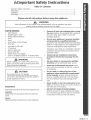
lmportant
PLease read aL! Lnstructions before usLng thLs appHanceo
If the information in this manual is not followed exactly, a fire or explosion may result
causing property damage, personal injury or death.
PARTS NEEDED;
• Tape Measure
Straight Edge or Ruler
Phillips Head Screwdriver
Level
Pencil
Wire Cutters or Wire Stripper
Wire Nuts
Volt Meter (0-250 VAC)
!" Hole Saw
Hand or Saber Saw
Drill and Drill Bit
Safety Gloves and Goggles
Cloth or cardboard (Optional - to Protect Floor)
WARNING
Before installing, turn power OFF at the service
panel. Lock service panel to prevent power from
being turned ON accidentally.
CAUTION
Do not use the oven for storage.
Unit is heavy and requires at least two people or
proper equipment to move.
Important:
Savetheseinstructionsforthelocalinspector'suse.
Installer:
Please leave the instructions with the unit for the
owner
Owner:
Please save these instructions for future reference.
Remove all tape and packaging before using
the oven, Destroy the packaging after unpacking
the oven, Never allow children to play with
packaging material,
Be sure your appliance is properly installed
and grounded by a qualified technician in
accordance with the National Electrical Code ANSI/
NFPA No. 7 latest edition (or the Canadian Electric
Code) and local electrical code requirements.
[mportant: Local codes vary_ Installation, electrical
connections and grounding must comply with all
applicable codes.
Install only per installation instructions
provided inthe literature package for this
oven,
Ask your dealer to recommend a qualified
technician and an authorized repair service.
Know how to disconnect the power to the
oven at the circuit breaker or fuse box in case of
an emergency,
Do not repair or replace any part of the
appliance unless specifically recommended
in the manuals. All other servicing should be
done by a qualified technician, This may"reduce
the risk of personal injury and damage to the
oven.
Never modify or alter the construction of an
oven by removing panels, wire covers, screws, or
any other part of the product.
DO NOT LIFT OVEN BY DOOR HANDLE.
Remove the door for easier handling and installa-
tion. See 'Removing the Oven Door' in the Mainte-
nance section of the Use and Care Manual.
English _ 1

Steps 1 through
1. Prepare Cabinets
General Instructions:
° The single oven can be installed under a counter or
in a wall or cabinet. The double oven can be
installed in a wall or cabinet.
. Choose a location away from strong drafts and
where electrical power can be provided.
, The oven support surface must be a minimum 3/4"
thick plywood platform. For single ovens, it must
support !50 pounds. For double ovens, it must
support 290 pounds. The platform must be solid,
level and flush with the bottom of the cabinet cut
out.
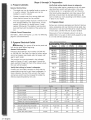
Cabinet Cutout Dimensions
See Table 2, below and Figures 2, 2 and 3 on following
page for cutout dimensions.
3: Preparation
Verify that wiring inside house is adequate,
Host wiring codes require a separate circuit with sepa-
rate disconnect switch and fuses either in the main
entrance panel or in a separate switch and fuse box.
Most local building regulations and codes require that
electrical wiring be done by licensed electricians. Be
sure to install your oven according to the electric codes
in place in your region.
3. Prepare Oven
Remove any remaining packaging and discard. Remove
racks, accessories and oven door(s) and set aside. See
instructions in Use and Care Manual for proper removal
of oven doors. DO NOT lift oven by door handles!
Place oven in front of cabinets where it is to be in=
stalled. Rest it on a jack or other sturdy support so that
it is in line with the cabinet cutout.
2. Prepare Electrical Outlet
_Waming; Turn power off at service panel and
lock service panel before beginning.
General Information
Ovens are dual rated for use on either :[20/240 VAC
or :[20/208 VAC. See Table 2 at right for power ratings
and circuit breaker sizes based upon the supply volt=
age for each model.
The junction box must be located in the indicated
space in Figures :[,2 and 3, next page. It should be
easily reached through the front of the cabinet where
the oven will be located.
Verify that wiring to house is adequate,
Contact your local utility company to verify that the
present electric service to your home is adequate. In
some instances, the size of the wiring to the house
and service switch must be increased to handle the
electrical load demanded by the oven.
Table 2: Electrical
Model
HBL503,
HBL504
HBL505,
HBL506
HBN504
HBN505
HBL73
HBL74,
HBN74
HBL75,
HBN75
HBL76,
HBN76
_ecifications
Vdt$
:[20/240
:[20/208
:[20/240
:[20/208
:[20/240
:[20/208
:[20/240
:[20/208
:[20/240
:[20/208
:[20/240
:[20/208
:[20/240
:[20/208
!20/240
:[20/208
Watts
3,350
6,350
5,300
3,250
2,820
6,250
5,400
3,600
2_500
%650
3_550
7,250
7:050
7,300
7_:[00
Amps
:[4
:[4.:[
26,25
25.25
:[3.5
:[3.6
26
26
:[5.4
:[7,2
:[5,8
17,6
3:[.2
34.8
3:[.6
35.2
A
B
C
D
E
F
Cutout Width
Cutout Depth
Cutout Height
Floor to Bottom of Cutout
Top of Cutout to Opening Above
Bottom of Cutout to Opening Below
i
28"
24"
23"
34"
1" min
1/4" min
25 3/8"
23"
34"
l"min
1/4"min
25 3/8"
47 13/16"
N/A
l"min
1/4"min
28"
24"
47 13/16"
N/A
1"min
1/4" min
G Top of Cutout to Top of Counter 4 1/2" min 4 1/2" min N/A N/A
H Side of Cutout to Adjacent Door or 1/4" min 1/4" min N/A N/A
Drawer Front
Oven Door Frame Width 26 5/8" 29 1/2" N/A N/A
2 * English

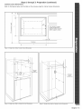
Steps 1 through 3: Preparation (continued)
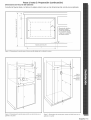
Cabinet Cutout Dimensions
Refer to the figures below and the table on the previous page for cabinet cutout dimensions.
2
G
v
C
m
_L
V
j'
I
J
A
E
-t
Oven electrical supply:
Locate junction box in
adjacent cabinet or below
bottom support surface.
ToeSpace
I i
Figure l: Single Oven Under Counter Cutout Dimensions
Electrical
supply
Jnction box
Electrical
supply
junction box
Figure 2: Single Oven Wall or Cabinet Cut-Out Dimensions
Figure 3: Double Oven Wall or Cabinet Cut-Out Dimensions
English _ 3

4° Connect Emectric
Verifythatelectrictothejunctionbox has been turned
offbeforebeginningthisstep,
General Instructions:
Use copper wire ONLY, Wire size and connections
must be suitable for the rating of the appliance per
the National Electrical Code requirements or the
Canadian Electric Code requirements.
. The flexible conduit extending from the oven
should be connected directly to the junction box.
Do not shorten flexible conduit,
. The junction box should be located to allow as
much slack as possible between the junction box
and the oven,
A UL listed conduit connector must be provided at
each end of the power supply cable,
The four wire branch drcuit connection is
preferred, but where local codes permit, a three
wire branch circuit connection is also acceptable.
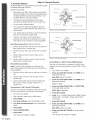
Step 4: Connect Electric
Junction box_
Red wires
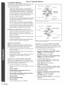
Four Wire Connection (Preferred Method):
!. Connect green ground wire from oven to green (or
bare) ground wire in junction box.
2. Connect red wire from oven to red wire in junction
box.
3. Connect black wire from oven to black wire in
junction box.
4. Connect white wire from oven to white (or gray)
neutral wire in junction box.
Three Wire Connection :
Note; The four wire connection is preferred, but
where local codes permit, the three wire connection is
also acceptable.
!. Connect red wire from oven to red wire in junction
box.
2. Connect black wire from oven to black wire in
junction box.
3. Connect both green ground wire and white wire
from oven to white (or gray) neutral wire in
junction box.
Connecting to a 208 V circuit (700 Series}:
The oven is pre=wiredfor connection to 240 V,60 Hz supply,
but can be convertedfor use with 208 V,60 Hzsupply.
!. Turn poweron a breaker.
2. Openoven door (upper oven in double ovens)
3. Press CANCEL.
4. Turn knob clockwise until 6 double beeps sound.
4. Turn knob ceuentercieckwise until 9 double beeps
sound.
5. Press START,
6. Press COOKING MODE,
7. Press START,
Time of dayclock appearsin display.
Cable from
power supply White wires
Ungrounded Neutral
Black wires
Bare or green wires Cable
from oven _ B,L,=listed conduit connector
Figure 4: Four Wire Connection
Junction box\ Cable from
_-_ power supply
Red wires Grounded Neutral
lack wires
Cable _ U,L,-[isted conduit connector
from oven
Figure 5: Three Wire Connection
Connecting to a 208 V circuit (50OO Series);
The oven is pre=wired for connection to 240 V, 60 Hz
supply, but can be converted for use with 208 V, 60 Hz
supply.
!. Turn power on a breaker.
2. Press and hemalSET CLOCK and TIMER for at
least three seconds.
Sele dEC appears in display.
3. Press and hoJd STOP TIME and TIMER for at
least three seconds.
Display is blank.
4. Press and hold COOK TIME and STOP TIME
for at least three seconds.
VOLT 240 is displayed.
5. Press SET CLOCK,
6. Press + or -to select appropriate voltage (choose
208 for 208 V connection; choose 240 to 240 V
connection).
7. Press SET CLOCK.
8. Press and hemalSTOP TIME and TIMER for at
least three seconds.
Sele dEC appears in display
8. Press and hold SET CLOCK for at least three
seconds.
Time of day clock appears in display.
4 * English

5o Install Oven
1.
2.
Step 5 and 6, Install Oven and Test Operation
Slide oven into cabinet cutout.
Push straight in until oven trim is flush with
cabinet wall, being careful not to crimp flexible con-
duit between oven and cabinet back wall. The oven
should be straight, not crooked.
Install screws (two or four depending on model)
through tap holes in trim.
6,Test Operation
For 700 SeriesModels;
1. Verify that all control knobs are in the OFF position.
2. Turn on power at the breaker.
The clock will appear in the display.
3. Check power at junction box using a volt meten
For 240 V installation, the reading between the red
and black wires (line to line) should be 220 to 240
volts.
For 208 V installation, the reading between the red
and black wires (line to line) should be !90 to 208
volts,
4. Test the oven mode.
Press COOKING HODE.
Turn knob to BAKE.
Touch START.
PREHEATappears in display.
When the oven has reached the set temperature
(350 ° F), it beeps and PREHEATno longer appears.
If installing a double oven, test the second oven as
well.
5. If any of the tests do not result as explained above,
contact Bosch service: 800-944-2904. Otherwise, the
installation is complete at this time.
4. Test the oven mode,
Turn cooking mode selector knob to BAKE. The
following should occur:
o 350 °F (the default baking temperature) and
COOK appear in the display.
Red preheat indicator lights up.
Oven light and fan turn on.
If installing a double oven, test the second oven
as well.
5. If any of the tests do not result as explained
above, contact Bosch service: 800-944-2904.
Otherwise, the installation is complete at this
time.
[:orSO00 Series Models:
1. Verify that all control knobs are in the OFF position.
2. Turn on power at the breaker.
The oven will beep and the dock will appear in the
display. The lock icons in the display will blink on
and off and you will hear a series of clicks as the
oven performs a system check.
When successfully completed, only the clock time
will appear in the display. The dock is preset to 12:00
AN.
3. Check power at junction box using a volt meter.
For 240 V installation, the reading between the red
and black wires (line to line) should be 220 to 240
volts.
For 208 V installation, the reading between the red
and black wires (line to line) should be 190 to 208
volts.
English _ 5

lnstrucciones lmportantes
Por favor lea todas las instrucciones antes de utilizar este aparatoo
El no observar la informaci6n en este manual puede causar un fuego o una explosi6n, y como resultado
da_os a la propiedad, lesiones o la muerte.
PARTE$ QUE SE NECE$ITAN:
Cinta de medir
Regla
• Destornillador de cabeza Phillips (de cruz)
Niveleta
L_piz
• Cortaalambres o pinzas para pelar cables
o Conectores de alambre
Volt[metro (0=250 VAC)
Cerrucho para orificio de 1 pulgada
Cerrucho de mano
Taladro y broca
• Guantes y lentes de seguridad
Trapo o cart6n (Opcional - para proteger el piso)
ADVERTENC][A
Antes de inst_alar,APAGUE la corriente en el
panel de servicio. Bloquee el panel para evitar
que se PRENDAla corriente accidentalmente.
PRECAUCI6N
No aImacenecosasen elhorno.
Elaparatoes pesado y requierede almenos dos
personaso un equipoapropiadoparamoverlo.
Importante:
Guarde estas instrucciones para el uso del inspector
local,
Instalador:
Pot favor deje las instrucciones con la unidad para el
propietario.
Propietario:
Pot favor guarde estas instrucdones para futuras refer°
endas.
• Quite las dntas adhesivas y los materiales
de empaque antes de usar el homo. Destruya
los materiales de empaque despu6s de desempa°
car el horno. Nunca permita que los niffos jueguen
con estos materiales.
Aseg_rese de que su aparato est_ insta[ado y
aterrizado correctamente pot un t_cnico
calificadode acuerdocon losrequedmientosdel
c6digo el6ctrico local y la tiltima edici6n del C6digo
EI6ctrico National ANSIiNFPA (o del C6digo
EI6ctdco de Canada).
Importante: Los c6digos locales pueden variar.
La instalaci6n, las conexiones el6ctricas y la puesta
a tierra deben cumplir con todos los c6digos
aplicables.
, Instate soJamente de acuerdo a [as
instruccionesde instalaci6nque se incluyen
en e[ paquete de [iteratura para este homo°
P[dalea su distribuidorque recomiende un
t_cnico ¢alificadoy un centrode servicio
autorizado,
Aprenda a desconectar [a corriente al homo
en el cortacircuitos o la caja de fusibles en caso de
una emergenda.
No trate de reparar o ree_piazar alguna
parte de[ aparato a _enos clue los manuales
1o reco_ienden especfficamente, Todo servicio
adidonal debe ser realizado por un t6cnico
calificado. Esto puede redudr el riesgo de lesiones
y daffos al homo.
Nunca modifique o altere [a construcci6n
de un homo quitando paneles, el revestimiento
de cables, torniHos o cualquier otra parte del
producto.
NO LEVANTE EL HORNO POR LA
AGARRADERA, Quite la puerta para facilitar el
manejo y la instalaci6n. Consulte la secci6n "Quitar
la puerta del Horno" en la secci6n de
mantenimiento del Manual de Uso y Cuidado.
Espa ol * 1

1. Preparar los Gabinetes
Instrucdones Generales_
@
Pasos 1 hasta 3: Preparaci6n
Se puede instalar el homo send[Io por debajo de la
cubierta de cocina o adentro de una pared o
un gabinete. Se puede instalar el doble homo en
una pared o un gabinete.
Escoja un lugar lejos de fuertes cordentes y donde
se pueda conectar a la cordente el_ctdca.
La superfide de soporte de[ homo debe ser una
plataforma de madera laminada con un grosor
mmimo de 3/4" que aguanta !50 libras. Para
homos dobles, debe soportar 290 libras. La plata°
forma debe set s6lida, nivelada y quedar a[ ras con
el rondo del recorte del gabinete.
Dimensiones de[ Recorte de[ Gabinete
Consulte la Tabla ! abajo y [as Figuras 1, 2 y 3 en la
siguiente p_gina para las dimensiones del recorte.
2. Preparar [a Tomacorriente
Advertenda; Apague la cordente en el panel
de servido y bloqu_elo antes de comenzar.
Informad6n Genera[
Las estufas tienen dobie r_gimen el_ctrico nominal para
!20/240 VAC o !20/208 VAC. Vea la tabia 2 para la da-
sificad6n ei_ctrica y el tamaffo del cortadrcuito basado
en el voltaje de alimentad6n para cada modelo.
Se debe co[ocar la caja de conexiones en el espado
indicado en las Figuras !, 2 y 3 de [a siguiente p_gina.
Debe set f_cil de akanzarla a trav_s de[ ffente del
gabinete donde se colocar_i el horno.
Verificar que e[ cab[carlo a [a casa est_ e[
adecuado
Contacte a su proveedor local de electriddad para
verificar que el servido el_ctrico actual sea el adecuado
para su casa. En algunos casos se debe aumentar el
tamaffo de[ cabieado a la casa y el interruptor de servi-
do para manejar la carga ei_ctdca exigida pot el homo.
A
B
C
D
E
i
Verificar q_e e[ cab[eado adentro de [a casa sea
el adec_ado.
La mayoffa de los c6digos de cableado requieren un
drcuito separado con un desconectador separado y
fusibles en el panel principal de entrada o en una caja
separada para el interruptor y para los fusibles.
La mayor[a de las regulaciones locales de construcd6n
requieren que un electrico calificado haga [as instalad-
ones el_ctricas. Aseg0rese de instalar su homo de acu-
erdo con los c6digos ei_ctdcos aplicables en su regi6n.
3, Preparar e[ Homo
Quite todo el material de empaque y des_chelo.
Saque las rejillas, accesonos y la puerta(s) del homo y
gu_irdelos a un lado. Vea las instrucdones en el Manual
de Uso y Cuidado para ver c6mo quitar la puerta, iNO
levante el homo pot las agarraderas de la puerta!
Coloque el homo enffente de los gabinetes donde
se debe instalar. Descanse el homo sobre un gato u
otto soporte robusto para que quede alineado con el
recorte para el gabinete.
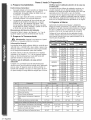
Tabla 2: Especificaciones El&tricas
Mode[o Vo[tios
HBL503,
HBL504
HBL505,
HBL506
HBN504
HBN505
HBL73
HBL74,
HBN74
HBL75,
HBN75
HBL76,
HBN76
!20/240
!20/208
!20/240
!20/208
!20/240
!20/208
!20/240
!20/208
!20/240
!20/208
!20/240
!20/208
120/240
!20/208
!20/240
!20/208
Ancho del Recorte
Profundidad del Recorte
Altura del Recorte
Piso at Fondo del Recorte
Parte Superior de! Recorte a Abertura
Alta
Fondo del Recorte a Abertura Baja
Watts Amps
3,350 14
2,925 14,i
6,350 26.25
5,300 25.25
3,250 !3.5
2,820 !3.6
6,250 26
5,400 26
3,600 15,4
2,500 !7.2
3_650 !5.8
3,550 17.6
_250 31.2
_050 34.8
7,300 31.6
7_100 35.2
25 3/8"
24
23"
34"
1" min
1/4" min
28"
24
23"
34"
1"min
1/4" min
G Parte Superior de! Recorte a la Cubierta 4 1/2" min 4 1/2" min
H Costado de! Recorte a la Puerta Adya - 1/4" min 1/4" min
cente o al Frente del Caj6n
[ Ancho del Marco de Puerta del Homo 26 5/8" 29 1/2"
253/5"
24
47 13/16"
N/A
1"min
28
24
47 13/i6"
N/A
I" min
1/4"min 1/4"min
N/A N/A
N/A N/A
N/A N/A
2 * Espa o[

Pasos 1 hasta 3: Preparaci6n (continuaci6n)
Di_ensione$ de Reco_e del Gabinete
Consulte las figuras abajo y la tabla en la p_igina anterior para ver las dimensiones del recorte para el gabinete.
v
k
KJ
U
¢)
r_
8
<C
Y
T_
\
............ J
m B
I
R A B
R B
I
H --
Espacio para Fospies
I
Alimentaci6n e!6ctrica
del homo: Iocalice
la caja de conexlones
en e/gabinete adjunto
o abajo de la superficie
del soporte inferior,
Figura 1: Dimensiones de recorte iaara el homo sencillo debajo de la cubierta de cocina
A
Caja de
mentaci6n
el_ctrica
Caja de
conexiones
para la
alimentaci6n
el_ctrica
Figura 2: Dimensiones de recorte para montar un solo homo en un
gabinete o la pared
Figura 3: Dimensiones de recorte para montar un doble homo en un
gabinete o la pared
Espa_ol _ 3

Paso 4: Cone×idn El ctrica
4. Cone×idn El ctrica
Vedfique que se haya apagada la electdcidad a la caja
de conexiones antes de comenzar con este paso.
Instrucciones Generales:
* Utilice SOLO cables de cobre. Los tamaffos de
cables y las conexiones deben set adecuadas para
la c[asificacidn de[ aparato seg_n los requefimien=
tos de[ Cddigo El_ctdco Nacional (o Canadiense).
, Se debe conectar el conducto flexible que sale del
homo directamente a [a caja de conexiones.
No torte el conducto flexible.
Se debe colocar [a caja de conexiones de tal forma
que permita el mayor juego posibIe entre la caja
de conexiones y el homo.
Se debe utilizar un conector de conducto listado
Caja de conexiones Cable de [a fuente
_. de a[imen_:addn
Cables blancos
Neutral No
Aterrizado
Cables verdes o desnudos
Cable
del homo _ Conector de conducto
listado con U,L,
Figura 4: Conexidn con cuatro hilos
con UL en cada extremo del cable de alimentaddn.
La conexidn de[ drcuito con cuatro hilos es prefer-
Die pero donde los cddigos locales Io permiten, se
acepta tambi6n una conexidn con tres hilos.
Conexidn con cuatro hilos (Hfitodo Prefeddo);
!. Conecte el cable verde de tierra del homo al cable
verde (o desnudo) en la caja de conexiones.
2. Conecte el cable rojo del homo al cable rojo en la
caja de conexiones.
3. Conecte el cable negro del homo al cane negro en
la caja de conexiones.
4. Conecte el cable blanco del homo al cable blanco
(o gris) neutral en la caja de conexiones.
Caja de conexiones_ Cable de la fuente
-. de alimentacidn
Cab{es rojos _ NeutrN de Tierra
Cables b[a__
__ "Cables negros
Cable verde o desnudo / _
CaMe _Conector de conducto
del homo [istado con U,L.
Figura 5: Conexidn con tres hilos
Conexidn con tres hilos:
Nora: La conexidn del drcuito con cuatro hilos es
preferible pero donde los cddigos locales 1opermiten,
se acepta tambi_n una conexidn con tres hilos.
!. Conecte el cable rojo del homo al cane rojo en la
caja de conexiones.
2. Conecte el cable negro de[ homo al cane negro en
la caja de conexiones.
3. Conecte ambos cables verde y blanco del homo al
cable bianco (o gris) neutral en la caja de
conexiones.
Conexidn a un circuito de 208 V (Serie 700);
El homo viene precableado para una conexidn a una
alimentacidn de 240 V, 60 Hz, pero se puede convertir
para una alimentaddn de 208 V, 60 Hz.
!. Prenda la cordente con un interruptor.
2. Abra la puerta del homo (homo superior en hornos
dobles)
3. Optima CANCEL,
4. Gire [a perii[a en sentido de[ reloj hasta
escuchar 6 pNdos dobles.
4. Gire [a peri[[a en sentido contrario de[ reloj
hasta escuchar 9 pitidos dobles.
5. Oprima START.
6. Optima COOKING NODE.
7. Optima START°
La hora del dia aparece en la pantalla.
Conexidn a un circuito de 208 V ($erie $000)_
El homo viene precableado para una conexidn a una
alimentaddn de 240 V, 60 Hz, pero se puede convertir
para una alimentaddn de 208 V, 60 Hz.
!. Prenda la corfiente con un interruptor.
2. Oprima y mantenga oprimido SET CLOCK y
TINIER pot al menos tres segundos.
Sele dEG aparece en la pantalla.
3. Optima y mantenga oprimido STOP TINE y
TINIER pot al menos tres segundos.
La pantalla est,1en blanco.
4. Press and hold COOK T:[NE y STOP TINE
pot al menos tres segundos.
VOLT 240 aparece en la pantalla.
5. Oprima SET CLOCK,
6. Press + o opara selecdonar el voltaje correcto
(escoja 208 para una conexidn de 208 V; escoja
240 para una conexidn de 240 V).
7. Optima SET CLOCK,
8. Optima y mantenga oprimido STOP TINE y
TINER pot al menos tres segundos.
Seine dEG aparece en la pantalla
8. Press and hold SET CLOCK pot al menos tres
segundos.
La hora del d[a aparece en la pantalla.
4 o Espafiol

Paso 5 y 6: InstaJar el Homo y Probar Ja Operaci6n
5. Instalar eL Homo
!. Inserte el homo en el recorte del gabinete.
2. Empuje el homo hada atr_is hasta que el borde
quede al ras con la pared del gabinete. Tenga cui-
dado para no doblar el conducto flexible entre
el homo y Japared trasera del gabinete. El homo
debe quedar en posid6n recta, no torcida.
2. Instale los tomillos (dos o cuatro dependiendo del
modelo) a trav6s de los agujeros para rosca
interior en la moldura.
6, Probar Jaoperad6n
Para Modelos de maSerie 700:
!. Verifique que todas las perillas de control est6n en la
posid6n de APAGADO.
2. Prenda la cordente en el interruptor.
El reloj aparece en la pantalla
3. Revise la cordente en la caja de conexiones con un
volt[metro.
Para una instalad6n de 240V, la lectura entre los
cables rojos y negros (l[nea a I[nea) debe set 220 a
240 voltios.
3. Revise la corriente en la caja de conexiones con
un volt[metro.
Para una instalad6n de 240V, la lectura entre los
cables rojos y negros (Hnea a linea) debe set 220
a 240 voltios.
Para una instalad6n de 208V, la lectura entre los
cables rojos y negros (l[nea a linea) debe set !90
a 208 voltios.
4. Vedfique el modo del horno.
Cambie la perilla de selecd6n del homo a BAKE
(Homear). Lo siguiente deber[a ocurrir:
o 350 °F (la temperatura pot default) y COOK
(Codnar) aparecen en la pantalla.
Se iluminan las luces rojas de precalentao
miento.
Se prenden la luz y el ventilador del homo.
Cuando instala un doble homo, aplique la misma
prueba tambi6n al otto horno.
5. Si alguna de las pruebas no resulta como se
describe ardba, contacate al servido de Bosch:
800-944-2904. De otto modo la instalad6n ya
termin6 en este momento.
Para una instalad6n de 208V, la lectura entre los
cables rojos y negros (Hnea a linea) debe ser !90 a
208 voltios.
4. Verifique el modo del homo.
Optima COOKING NODE.
Gire la perilla a BAKE (Hornear).
Optima START (Inicio).
PREHEAT(Precalentar) aparece en la pantalla.
Cuando el homo haya alcanzado la temperatura
determinada (350° F), emite pitidos y PREHEATdeja
de aparecer en la pantalla.
Cuando instala un doble homo, aplique la misma
prueba tambi6n al otto homo.
5. Si alguna de las pruebas no resulta como se
describe arriba, contacte al servicio de Bosch:
800-944-2904. De otto modo la instalaci6n ya
termin6 en este momento.
Para Modeios de la Serie 5000
2.
Vedfique que todas las perillas de control est6n
en la posici6n de APAGADO.
Prenda la corriente en el interruptor.
El homo emitir_i un pitido y el reloj aparecer_i en
la pantalla. Los iconos de bloqueo parpadear_in
en la pantalla y usted podr_i escuchar una serie
de chasquidos mientras el homo realiza un
chequeo del sistema.
Una vez que termina el homo, s61oaparecer_ la
hora del reloj en la pantalla. El reloj queda pre-
configurado para las !2:00 AN.
Espa_ol o !

BSH reserves the right to change specifications or design without notice. Some models are certified for use in Canada. BSH is not responsibFe
for products which are transported from the United States for use in Canada. Check with your FocaFCanadian distributor or dearer. BSH Home
AppFiances, Corporation, 5551 McFadden Avenue, Huntington Beach, CA 92649.
For the most up to date critical installation dimensions by fax_ use your fax handset and call 702-833-3600. Use code #8030.
YOJR L!FE OUR INSP RATION,
5551 NcFadden Avenue, Huntington Beach, CA 92649 _ 800-944-2904 _ www.boschappliances.com
9000053251 (No ECO) • 10002 Rev C _ 9/05 © BSH Home Appliances Corporation 2005 • Litho U.S A.
-
 1
1
-
 2
2
-
 3
3
-
 4
4
-
 5
5
-
 6
6
-
 7
7
-
 8
8
-
 9
9
-
 10
10
-
 11
11
-
 12
12


Bosch HBL742AUC/02 Guía de instalación
- Categoría
- Hornos
- Tipo
- Guía de instalación
- Este manual también es adecuado para
en otros idiomas
Artículos relacionados
Otros documentos
-
GE JK1000DF1BB Installation Instructions Manual
-
Kenmore 79040452801 Guía de instalación
-
Electrolux EW30EC55GB2 Guía de instalación
-
Kenmore 79047849407 Guía de instalación
-
Frigidaire FPET3085KFC Guía de instalación
-
-
Frigidaire GLEB27M9FBA Guía de instalación
-