Craftsman 580323601 El manual del propietario
- Categoría
- Generadores de poder
- Tipo
- El manual del propietario

Owner's Manual
ICRRFTSMRN+I
AC Generator
3600 Watt
Model No.
580.323601
CusGemn:/at°lplin e_
HOURS: Mon. - Fri. 8 a.m. to 5 p.m. (CT)
CAUTION:
Before using this product, read this
manual and follow all its Safety Rules
and Operating Instructions.
Sears, Roebuck and Co., Hoffman Estates, IL 60179
Visit our Craftsman website: www.sears.comlcraftsman
Past No. 192788GS Drai'_0 (03/07/2003)
• Safety
• Assembly
• Operation
• Maintenance
• Parts
• Espafiol
01!!!U!!!!U!.,

WARRANTY ............................. 2
SAFETY RULES ........................ 3-4
KNOW YOUR GENERATOR ................ 5
ASSEMBLY ............................ 6-7
OPERATION .......................... 8-10
SPECIFICATIONS ....................... 11
MAINTENANCE ....................... 11-13
STORAGE ............................. 13
TROUBLESHOOTING .................... 14
NOTES ............................ 15 & 26
SCHEMATIC/WIRING DIAGRAM ............ 16
REPLACEMENT PARTS ................ 17-25
EMISSION SYSTEM WARRANTY ........... 27
ESPANOL ........................... 28-43
HOW TO ORDER PARTS .......... BACK PAGE
LIMITED WARRANTY FOR CRAFTSMAN GENERATORS
SEARS warrants to the original purchaser that the alternator and engine for itsportable generator will be free
from defects in materials or workmanship for the items and period set forth below from the date of original
purchase. This warranty is not transferable.
CONSUMER* COMMERCIAL*
Alternator 2 Years (2nd year parts only) 1 Year
Engine 2 Years (2nd year parts only) 1 Year
* NOTE: For the purpose of this warranty "Consumer Use" means personal residential household and emergency
use by original purchaser, not to be used as a primary source of power. "Commercial Use" means all other uses,
including rental, construction, commercial, and income producing purposes. Once a generator has experienced
commercial use, it shall thereafter be considered a commercial use generator for the purpose of this warranty.
During said warranty period, SEARS will, at its option, repair or replace any part which, upon examination by
SEARS, is found to be defective under normal use and service**. Starting batteries are not warranted by SEARS.
All transportation costs under warranty, including return to the factory if necessary, are to be borne by the
purchaser and prepaid by him. This warranty does not cover normal maintenance and service and does not apply
to a generator set, alternator or engine, or parts which have been subjected to improper or unauthorized
installation or alteration, misuse, negligence, accident, overloading, over-speeding, improper maintenance, repair
or storage so as, in SEARS's judgment, to adversely affect its performance and reliability.
** NORMAL WEAR: As with all mechanical devices, engines need periodic parts service and replacement to
perform well. This warranty will not cover repair when normal use has exhausted the life of a part or engine.
THERE IS NO OTHER EXPRESS WARRANTY. SEARS HEREBY DISCLAIMS ANY AND ALL IMPLIED
WARRANTIES, INCLUDING BUT NOT LIMITED TO THOSE OF MERCHANTABILITY AND FITNESS
FOR A PARTICULAR PURPOSE TO THE EXTENT PERMITTED BY LAW. THE DURATION OF ANY
IMPLIED WARRANTIES WHICH CANNOT BE DISCLAIMED IS LIMITED TO THE TIME PERIOD AS
SPECIFIED IN THE EXPRESS WARRANTY. LIABILITY FOR CONSEQUENTIAL, INCIDENTAL, OR
SPECIAL DAMAGES UNDER ANY AND ALL WARRANTIES IS EXCLUDED.
Some states do not allow limitations on how long an implied warranty lasts, or the exclusion or limitation of
incidental or consequential damages, so the above limitations or exclusions may not apply to you. This warranty
gives you specific legal rights and you may also have other rights, which vary from state to state.
For service, see your nearest SEARS authorized warranty service facility. Warranty service can be performed
only by a SEARS authorized service facility. This warranty wilt not apply to service at any other facility. At the time
of requesting warranty service, evidence of original purchase date must be presented.
SEARS, ROEBUCK and CO., D/817WA, Hoffman Estates, IL 60179 U.S.A.
2

A
_Read this manual carefully and become
familiar with your pressure washer. Know its
applications, its limitations, and any hazards
involved.
This is the safety alert symbol. It is used to alert you to potential personal injury hazards.
Obey all safety messages that follow this symbol to avoid possible injury or death.
The safety alert symbol (,_) is used with a signal
word (DANGER, CAUTION, WARNING), a pictorial
and/or a safety message to alert you to hazards.
DANGER indicates a hazard which, if not avoided, will
result in death or serious injury. WARNING indicates a
hazard which, if not avoided, could result in death or
serious injury. CAUTION indicates a hazard which, if
not avoided, might result in minor or moderate injury.
CAUTION, when used without the alert symbol,
indicates a situation that could result in equipment
damage. Follow safety messages to avoid or reduce
the risk of injury or death.
In the State of California a spark arrester is required
3y taw (Section 4442 of the California Public
Resources Code). Other states may have similar laws.
;ederal laws apply on federal lands. If you equip the
"nuffter with a spark arrester, it must be maintained in
_=ffective working order.You can order a spark arrester
through your authorized Sears service dealer.
A WARNING I
The engine exhaust from this product contains I
chemicals known to the State of California to cause
cancer, b rth defects, or other reproduct ve harm,
WARNING
This generator does not meet U. S. Coast Guard
Regulation 33CFR-183 and should not be used on
marine applications.
Failure to use the appropriate U. S. Coast Guard
approved generator could result in bodily injury and/or
property damage.
DANGER
DO NOT allow any open flame, spark, heat, or lit cigarette
during and for several minutes after charging a battery.
Wear protective goggles, rubber apron, and rubber gloves.
DANGER
Operate generator ONLY outdoors.
Keep at least 2 feet of clearance on all sides of
generator for adequate ventilation.
DO NOT operate generator inside any building or
enclosure, including the generator compartment of a
recreational vehicle (RV).
kDANGER
National Electric Code requires generator to be properly
grounded to an approved earth ground. Call an
electrician for local grounding requirements.
DANGER
When using generator for backup power, notify utility
company. Use approved transfer equipment to isolate
generator from electric utility.
Use a ground circuit fault interrupter (GFCI) in any damp
or highly conductive area, such as metal decking or steel
work.
DO NOT touch bare wires or receptacles.
DO NOT use generator with electrical cords which are
worn, frayed, bare or otherwise damaged.
DO NOT operate generator in the rain.
DO NOT handle generator or electrical cords while
standing in water, while barefoot, or while hands or feet
are wet.
DO NOT allow unqualified persons or children to operate
or service generator.
WARNING
;ENERATOR
Disconnect the spark plug wire from the spark plug and
place the wire where it cannot contact spark plug.
3

WARNING
WHEN ADDING FUEL
Turn generator OFF and let it cool at least 2 minutes
before removing fuel cap. Loosen cap slowly to relieve
pressure in tank.
Fill fuel tank outdoors.
DO NOT overfill tank. Allow space for fuel expansion.
Keep fuel away from sparks, open flames, pilot lights,
heat, and other ignition sources.
DO NOT light a cigarette or smoke.
_/HEN OPERATING EQUIPMENT
Do not tip engine or equipment at angle which causes
fuel to spill.
This generator is not for use in mobile equipment or
marine applications.
_/HEN TRANSPORTING OR REPAIRING EQUIPMENT
Transport/repair with fuel tank EMPTY or with fuel shutoff
valve OFF.
Disconnect spark plug wire.
_/HEN STORING FUEL OR EQUIPMENT WITH FUEL IN
TANK
Store away from furnaces, stoves, water heaters, clothes
dryers or other appliances that have pilot light or other
ignition source because they can ignite fuel vapors.
WARNING
DO NOT touch hot surfaces.
Allow equipment to cool before touching,
CAUTION
DO NOT tamper with governed speed. Generator
supplies correct rated frequency and voltage when
running at governed speed.
DO NOT modify generator in any way.
CAUTION
See "Don't Overload Generator" on page 10.
Start generator and let engine stabilize before connectin
electrical loads.
Connect electrical loads in OFF position, then turn ON
for operation.
Turn electrical loads OFF and disconnect from generatol
before stopping generator.
CAUTION
Use generator only for intended uses.
If you have questions about intended use, ask dealer or
contact Sears.
Operate generator only on level surfaces.
DO NOT expose generator to excessive moisture, dust,
dirt, or corrosive vapors.
DO NOT insert any objects through cooling slots.
If connected devices overheat, turn them off and
disconnect them from generator.
Shut off generator if:
-electrical output is lost;
-equipment sparks, smokes, or emits flames;
-unit vibrates excessively.
4

KNOW YOUR GENERATOR
Read the owner's manual and safety rules before operating your generator.
Compare the illustrations with your generator to familiarize yourself with the locations of various controls and
adjustments. Save this manual for future reference.
FuetTank
Rocker Switch
Oil Fill Cap/Dipstick
Recoil Starter
120 Volt AC, 20 Amp
Duplex Receptacles
Choke Lever
Air
120/240 Volt AC, 20 Amp
Receptacles
Spark Arrester
Muffler
Circuit Breake_
120 Volt AC, 20 Amp, Duplex Receptacles -- May
be used to supply electrical power for the operation of
120 Volt AC, 20 Amp, single phase, 60 Hz electrical,
lighting, appliance, tool and motor loads.
120/240 Volt AC, 20 Amp Locking Receptacle --
May be used to supply electrical power for the
operation of 120 and/or 240 Volt AC, 20 Amp, single
phase, 60 Hz electrical, lighting, appliance, tool and
motor loads.
Air Cleaner -- Filters intake air as it is drawn into the
engine.
Circuit Breakers -- Each receptacle socket is
protected against electrical overload with "push to
reset" circuit breakers.
Grounding Fastener
Fuel Tank -- Tank holds 4 U.S. gallon of unleaded
fuel.
Grounding Fastener-- Ground the generator to an
approved earth ground here.
Oil Fill Cap/Dipstick -- Check and fill engine with oil
here. See page 7 for oil recommendations and filling
instructions.
Choke Lever -- Used when starting a cold engine.
Recoil Starter -- Used for starting the engine.
Rocker Switch -- Set switch to "On" prior to using
recoil starter. Set switch to "Off" to switch off engine.
Spark Attester Muffler -- Exhaust muffler lowers
engine noise and is equipped with a spark arrester
screen.
5

TO REMOVE GENERATOR FROM
CARTON
Open top flaps of shipping carton.
Slice two corners at end of carton from top to
bottom so the panel can be folded down fiat, then
remove all packing material.
Remove the generator and contents from the
shipping carton.
CARTON CONTENTS
Check all contents against those listed below:
Main unit
Engine oil
Owner's manual
Wheel Kit
If any parts are missing or damaged, call the
generator hetpline at 1-800-222-3136.
INSTALL WHEEL KIT
NOTE: While the wheel kit is designed to greatly
improve the portability of your generator, it is not
intended for over-the-road use.
You will need a socket wrench with 1/2" or 13mm
sockets, a 5/16" wrench and a needle-nose pliers to
install this kit.
Install the Wheel Kit as Follows:
1. Place bottom of generator cradle on a flat surface.
2. Place axle stud through wheel retainer on cradle
frame, as shown below.
3. Use 15/16" wrench to secure axle stud to frame
with 5/8-18 jam nut.
4. Install other axle stud in same manner.
NOTE: Be sure to install wheel with raised hub inboard.
5. Tip unit and install wheel. Place flat washer over
axle stud.
6. Retain wheel on axle stud with retaining pin.
Install other wheel on remaining axle stud the
same way.
7. Attach support leg using two 13mm wrenches with
20mm cap screws and lock nuts.
8. Center lifting handle on generator end of cradle.
Attach handle using two 13mm wrenches with
capscrews and hex nuts.
Capscrew
Jam Nut
Washer
Mountin
Axle
Stud
\ / /
Capscrew /
Wheel Retaining Pin
6

BEFORE STARTING THE
GENERATOR
Add Engine Oil
IMPORTANT: Any attempt to crank or start the engine
before it has been properly serviced with the
recommended oil may result in an engine failure.
NOTE: When adding oil to the engine crankcase, use
only high quality detergent oil rated with API service
classification SF, SG, SH, SJ or higher rated
SAE 30 weight. Do Not use special additives.
1. Choose a viscosity according to the table below:
**mm
IE*
J
._ -2o, o 2o 3_ 4o _o _o _oo
STARTING TEMPERATURE RANGE ANTiCiPATED BEFORE NEXT OiL CHANGE
* The use of multi-viscosity oils (5W-30, 10W-30, etc.)
in temperatures above 40°F (4°C) will result in higher
than normal oil consumption. When using a multi-
viscosity oil, check oil more frequently.
** If using SAE 30 oil in temperatures below 40°F
(4°C), it will result in hard starting and possible engine
bore damage due to inadequate lubrication.
1. Place generator on a level surface.
2. Clean area around oil fill and remove oil dipstick.
3. Wipe dipstick clean. Pour oil into oil fill opening.
Replace and tighten dipstick.
4. Pause to permit oil to settle. Remove and and
check oil level. Oil level should be at "Full" mark
on dipstick. DO NOT OVERFILL.
Add Fuel
,_ WARNINGI NEVER fill fuel tank indoors.
NEVER fill fuel tank when engine is running or
hot. Allow unit to cool for two minutes before
refueling. DO NOT light a cigarette or smoke
when filling the fuel tank.
,_ WARNINGI DO NOT overfill the fuel tank.
Always leave room for expansion.
1. Use regular UNLEADED fuel with generator
engine. DO NOT use premium fuel. DO NOT mix
oil with fuel.
2. Clean area around fuel fill cap, remove cap.
3. Slowly add unleaded regular fuel to fuel tank. Be
careful not to overfill. Allow about 1.5 of tank
space for fuel expansion, as shown here.
Fuel
_NNNN_N_NN_NNNN_
_NNNNNNNNNN_NNNN,
4. Install fuel cap and wipe up any spilled fuel.
IMPORTANT: It is important to prevent gum deposits
from forming in fuel system parts such as the
carburetor, fuel hose or tank during storage. Alcohol-
blended fuels (called gasohol, ethanol or methanol)
can attract moisture, which leads to separation and
formation of acids during storage. Acidic gas can
damage the fuel system of an engine while in storage.
To avoid engine problems, the fuel system should be
emptied before storage of 30 days or longer.
See "Storage" on page 13. NEVER use engine or
carburetor cleaner products in the fuel tank as
permanent damage may occur.
NOTE: You may not need to use all the supplied oil.
5. Install oil dipstick, hand tighten securely.
NOTE: Check oil often during engine break-in.
7

HOW TO USE YOUR GENERATOR
If you have any problems operating your generator
after reading the manual, please call the generator
hetpline at 1-800-222-3136.
Grounding The Generator
The National Electrical Code requires that the frame
and external electrically conductive parts of this
generator be properly connected to an approved earth
ground. Local electrical codes may also require proper
grounding of the unit. For that purpose, a grounding
fastener is provided on the generator housing.
Grounding
Fastener _ \_\
Generally, connecting a No. 12 AWG (American Wire
Gauge) stranded copper wire to the grounding
fastener and to an earth-driven copper or brass
grounding rod (electrode) provides adequate
protection against electrical shock. However, local
codes vary widely. Consult with a local electrician for
grounding requirements in your area.
Proper grounding of generator will help prevent
electrical shock in the event of a ground fault condition
in the generator or in connected electrical devices,
especially if the unit is equipped with a wheel kit.
Proper grounding also helps dissipate static electricity,
which often builds up in ungrounded devices.
To Start The Engine
CAUTION! NEVER start or stop the engine with
electrical loads connected to the receptacles AND with
the connected devices turned ON.
Disconnect all electrical loads from the generator.
Follow start instruction steps in numerical order:
1. Make sure unit is on a level surface.
IMPORTANT: Failure to start and operate unit on a
level surface will cause the unit not to start or shut
down during operation.
2. Turn fuel valve to "On" position. Fuel valve handle
should be vertical (pointing toward ground) for fuel
to flow.
Fuel Valve is shown
in the On position
3. Place choke lever in "Choke" position.
4. Set rocker switch to "On" position.
Rocker Switch is
shown in On position
5. Grasp recoil handle and pull slowly until slight
resistance is felt. Then pull rapidly to start engine.
6. Move choke lever to "Run" position a short
distance at a time over several seconds in warm
weather or minutes in cold weather. Let engine
run smoothly before each change. Operate with
choke in "Run" position.
NOTE: If engine starts after 3 pulls but fails to run, or
if unit shuts down during operation, make sure unit is
on a level surface and check for proper oil level in
crankcase. This unit may be equipped with a low oil
protection device.
Connecting Electrical Loads
Let the engine stabilize and warm up for a few
minutes after starting.
DO NOT connect 240 Volt loads to 120 Volt
receptacles.
DO NOT connect 3-phase loads to the generator.
DO NOT connect 50 Hz loads to the generator.
Plug in and turn on the desired 120 Volt AC, single
phase, 60 Hertz electrical loads.
DO NOT OVERLOAD THE GENERATOR. See
"Don't Overload Generator" on page 10.
Stopping the Engine
1. Unplug all electrical loads from unit. NEVER start
or stop engine with electrical devices plugged in
and turned on.
2. Let engine run at no-load for two minutes to
stabilize unit's internal temperatures.
3. Move rocker switch to "Off" position.
4. Move fuel valve to "Off" position.
CORD SETS AND RECEPTACLES
Use only high quality, well-insulated, extension cords
with the generator's 120 Volt electrical receptacles.
Check the ratings of all extension cords before you
use them. Extension cord sets used should be rated
for 125 Volt AC loads at 20 Amps or greater for most
electrical devices. Some devices, however, may not
require this type of extension cord. Check the owner's
manuals of those devices for the manufacturer's
recommendations.
8

Keep extension cords as short as possible, preferably
less than 15 feet long, to prevent voltage drop and
possible overheating of wires.
120 Volt AC, 20 Amp Duplex Receptacle
Each receptacle is protected against overload by a
single 15 Amp push-to-reset circuit breaker. Use each
receptacle to operate 120 Volt AC, single phase 60 Hz
electrical loads requiring up to 2,400 watts (2.4 kW) at
20 Amps of current.
120/240 Volt AC, 20 Amp Receptacle
This is a full capacity receptacle; it can supply the
generator's full rated output from this sole outlet. The
outlet is protected by two 15 Amp push-to-reset
circuit breakers.
4-Wire Cord Set
1. Make sure generator has clean, fresh fuel.
2. Open fuel tank valve (turn valve to open position).
3. Use SAE 5W-30 oil (synthetic preferred, see
page 7).
4. Check oil level daily or after every eight (8) hours
of operation.
5. Change oil every 24 hours of operation.
6. Shelter unit from elements.
In an emergency, use the original shipping carton as a
temporary shelter:
1. Cut off all carton flaps.
2. Cut out one of the tong sides of carton to expose
muffler side of unit as shown below. Ensure a
minimum of two feet clearance between open side
of carton and nearest object.
/
(Neutral)
Y (Hot) / X (Hot)
/
NEMA L14-20 _ Ground (Green)
A NEMA L14-20 plug is used with this 240 Volt
receptacle. Connect a suitable 4-wire cord set to the
plug and to the desired load. The cord set should be
rated for 250 Volt AC loads at 20 Amps (or greater).
A
CAUTION! Although this receptacle is rated for
120/240 Volts at 20 Amps (4,800 watts or
4.8 kW), the generator is rated for a total of
3,600 watts at 15 Amps. Powering loads that
exceed the wattage capacity of the generator
can damage it or cause serious injuries. See
"Don't Overload Generator" on page 10.
COLD WEATHER OPERATION
Under certain weather conditions (temperatures below
40°F [4°C] combined with high humidity), your
Craftsman generator may experience icing of the
carburetor and/or the crankcase breather system. To
reduce this problem, you need to perform the
following:
Muffler side exposed. Your unit may differ in
appearance from that shown above.
3. Cut appropriate slots to access receptacles of unit.
4. Start unit, then place carton over it.
NOTE: Remove carton when temperature is above
40°F [4°C].
For a more permanent shelter, build a structure that
will enclose three sides and the top of the generator.
1. Make sure entire muffler-side of generator is
exposed, as shown.
2. Ensure a minimum of two feet clearance between
open side of structure and nearest object.
3. Face exposed end away from wind and elements.
4. Structure should hold enough heat created by
generator to prevent icing problem.
,_ WARNING! Engines give off carbon monoxide,
an odorless, colorless, poison gas. Breathing
carbon monoxide can cause nausea, fainting or
death.
5. Start and run engine outdoors.
6. DO NOT start or run engine in enclosed area,
even if doors or windows are open.
7. DO NOT enclose generator any more than shown.
8. Remove shelter when temperatures are above
40°F [4°C].
9. Turn engine OFF and let cool two (2) minutes
before refueling.
9

DON'T OVERLOAD GENERATOR
Capacity
You must make sure your generator can supply
enough rated (running) and surge (starting) watts for
the items you will power at the same time. Follow
these simple steps:
1. Select the items you will power at the same time.
2. Total the rated (running) watts of these items. This
is the amount of power your generator must
produce to keep your items running.
3. Estimate how many surge (starting) watts you will
need. Surge wattage is the short burst of power
needed to start electric motor-driven tools or
appliances such as a circular saw or refrigerator.
Because not all motors start at the same time,
total surge watts can be estimated by adding only
the item(s) with the highest additional surge watts
to the total rated watts from step 2.
Example:
Tool or Appliance
Window Air
Conditioner
Refrigerator
Deep Freezer
Television
Light (75 Watts)
Rated
(Running) Watts
1200
8O0
5O0
500
75
3075 Total
RunningWatts
Total Rated (Running) Watts
Highest Additional Surge Watts
Total Generator Output Required
Power Management
Additional Surge
(Starting)Wa_s
1800
1600
5O0
1800 Highest
Su_eWatts
= 3075
= 1800
= 4875
To prolong the life of your generator and attached
devices, it is important to take care when adding
electrical loads to your generator. There should be
nothing connected to the generator outlets before
starting it's engine. The correct and safe way to
manage generator power is to sequentially add loads
as follows:
1. With nothing connected to the generator, start the
engine as described in this manual.
2. Plug in and turn on the first load, preferably the
largest load you have.
3. Permit the generator output to stabilize (engine
runs smoothly and attached device operates
properly).
4. Plug in and turn on the next load.
5. Again, permit the generator to stabilize.
6. Repeat steps 4 and 5 for each additional load.
NEVER add more loads than the generator capacity.
Take special care to consider surge loads in generator
capacity, as described above.
Tool or Appliance
Essentials
Light Bulb - 75 watt
Deep Freezer
Sump Pump
Refrigerator/Freezer - 18 Cu, Ft,
Water Well Pump- 1/3 HP
HeatinglCeeling
Window AC - 10,000 BTU
Window Fan
Furnace Fan Blower - 1/2 HP
Kitchen
Microwave Oven - 1000 Watt
Coffee Maker
Electric Stove - Single Element
Hot Plate
Family Room
DVD/CD Player
VCR
Stereo Receiver
Color Television - 27"
Personal Computer w/17"
monitor
Other
Security System
AM/FM Clock Radio
Garage Door Opener - 1/2 HP
Electric Water Heater - 40
Gallon
DIY/Job Site
Quartz Halogen Work Light
Airless Sprayer - 1/3 HP
Reciprocating Saw
Electric Drill - 1/2 HP
Circular Saw - 7 1/4"
Miter Saw - 10"
Table Planer - 6"
Table Saw/Radial Arm Saw - 10"
Air Compressor - 1-1/2 HP
Rated* Additional
(Running) Sure
Wa_s (Starting)
Wa_s
75
500 500
800 1200
800 1600
1000 2000
1200 1800
300 600
800 1300
1000
1500
1500
2500
100
100
450
500
800
180
300
480 520
4000
1000
600 1200
960 960
1000 1000
1500 1500
1800 1800
1800 1800
2000 2000
2500 2500
*Wattages listed are approximate only. Check tool or
appliance for actual wattage.
10

MAINTENANCE SCHEDULE
Follow the hourly or calendar intervals, whichever occurs first.
More frequent service is required when operating in adverse conditions noted below.
MAINTENANCE SCHEDULE
FILL IN DATES AS YOU COMPLETE
REGULAR SERVICE
MAINTENANCE TASK
HOURLY OPERATING
INTERVAL
Before
Each Use
SERVICE DATES
ENGINE
X
Check oil level
Change engine oil X= I
Service air cleaner I X_ I
Service spark plug I X I
Service spark attester X I
Prepare for storage I If unit is to remain idle for
I
I longer than 30 days. I
Clean if clogged. Replace if perforated or torn.
2 Change oil after the first (5) operating hours and every 50 hours or every year, whichever occurs first, thereafter.
Change sooner when operating under dirty or dusty conditions.
3 Replace more often under dirty or dusty conditions.
PRODUCT SPECIFICATIONS
Generator Specifications
Rated Running Watts ......... 3,600 Watts (3.6kW)
Rated Surge Watts ........... 5,300 Watts (5.3kW)
Rated AC Voltage ............ 120/240 Volts
Rated Maximum AC Current
at 240 Volts .............. 15.0 Amperes
at 120 Volts .............. 30.0 Amperes
Rated Frequency ............ 60 Hz at 3600 rpm
Phase ..................... Single Phase
Shipping Weight ............. 127 Ibs.
Engine Specifications
Rated Horsepower ........... 7.0 at 3600 rpm
Displacement ............... 206cc
Spark Plug Type: ............ Champion RC-12YC
or Equivalent
Set Gap To: ................ 0.030inch (0.76mm)
Fuel Capacity ............... 4 U.S. gallon
Oil
Above 40°F .......... SAE 30
0°F -4O°F ........... SAE 5W-30 or 10W-30
GENERAL RECOMMENDATIONS
The generator warranty does not cover items that
have been subjected to operator abuse or negligence.
To receive full value from the warranty, operator must
maintain generator as instructed in this manual.
Some adjustments will need to be made periodically to
properly maintain your generator.
All adjustments in this section should be made at least
once each season. Follow the requirements in the
"Maintenance Schedule" chart shown above.
NOTE: Once a year you should clean or replace the
spark plug and replace the air filter. A new spark plug
and clean air filter assure proper fuel-air mixture and
help your engine run better and last longer.
GENERATOR MAINTENANCE
Generator maintenance consists of keeping the unit
clean and dry. Operate and store the unit in a clean
dry environment where it witl not be exposed to
excessive dust, dirt, moisture or any corrosive vapors.
Cooling air slots in the generator must not become
clogged with snow, leaves,or any other foreign
material.
Check the cleanliness of the generator frequently and
clean when dust, dirt, oil, moisture or other foreign
substances are visible on its exterior surface.
11

NOTE:DONOTuseagardenhosetoclean
generator.Watercanentertheenginefuelsystemand
causeproblems.Inaddition,ifwaterentersthe
generatorthroughcoolingairslots,someofthewater
willberetainedinvoidsandcracksoftherotorand
statorwindinginsulation.Wateranddirtbuilduponthe
generatorinternalwindingswilteventuallydecrease
theinsulationresistanceofthesewindings.
To Clean the Generator
Use a damp cloth to wipe exterior surfaces clean.
Use a soft bristle brush to loosen caked on dirt, oil,
etc.
,_ CAUTIONI NEVER insert any object or tool
through the air cooling slots, even ifthe engine
is not running.
Use a vacuum cleaner to pick up loose dirt and
debris.
Use low pressure air (not to exceed 25 psi) to blow
away dirt. Inspect cooling air slots and openings on
the generator. These openings must be kept clean
and unobstructed.
ENGINE MAINTENANCE
,_ CAUTIONI When working on the generator
always disconnect spark plug wire from spark
plug and keep it away from spark plug.
Checking Oil Level
Oil level should be checked prior to each use or at least
every 5 hours of operation. Keep oil level maintained.
Changing Engine Oil
Change the oil after the first 5 hours of operation.
Change oil every 50 hours thereafter. If you are using
your generator under extremely dirty or dusty
conditions, or in extremely hot weather, change the oil
more often.
Change the oil while the engine is still warm from
running, as follows:
1. Clean area around oil drain plug. The oil drain
plug is located at base of engine, opposite
carburetor.
2. Remove oil drain plug and drain oil completely into
a suitable container.
3. Install oil drain plug and tighten securely.
4. Fill oil sump with recommended oil. See page 7
for oil recommendations.
5. Install oil cap/dipstick. Check oil level. Tighten cap
securely.
6. Wipe up any spilled oil.
Clean/Replace Spark Plug
Change the spark plug every 100 hours of operation
or once each year, whichever comes first. This wilt
help your engine to start easier and run better.
1. Clean area around spark plug.
2. Remove and inspect spark plug.
3. Replace spark plug ifelectrodes are pitted or
burned or porcelain is cracked. For replacement
use Champion RC-12YC or equivalent.
4. Check electrode gap with wire feeler gauge and
set spark plug gap to 0.030 inch (0.76mm) if
necessary.
5. Install spark plug and tighten firmly.
NOTE: You can purchase a new spark plug by calling
1-800-366-PART.
Service Air Cleaner
Your engine will not run properly and may be
damaged if you run it with a dirty air cleaner.
Replace the air cleaner every 100 hours of operation
or once each year, whichever comes first. Replace
more often if operating under dirty or dusty conditions.
To service the air cleaner, follow these steps:
1. Loosen screw and tilt cover down.
CARTRIDGE BASE -_
COVER
SLOTS AND
SCREW----_ TABS
2. Carefully remove cartridge assembly.
3. To clean cartridge, gently tap pleated paper side
on a flat surface.
4. Reinstall clean or new cartridge inside cover.
5. Insert cover's tabs into slots in bottom of base.
6. Tilt cover up and tighten screw securely to base.
NOTE: You can purchase new air filter elements by
calling 1-800-366-PART.
12

Carburetor
If you think your carburetor needs adjusting, see your
nearest Sears service center. Engine performance
may be affected at attitudes above 3000-5000 feet.
For operation at higher elevations, contact your
nearest Sears service center.
Clean Spark Arrester Screen
The engine exhaust muffler has a spark arrester
screen. Inspect and clean the screen every 100 hours
of operation or once each year, whichever comes first.
NOTE: If you use your generator on any forest-
covered, brush-covered, or grass-covered unimproved
land, it must have a spark arrester. The spark arrester
must be maintained in good condition by the
owner/operator.
Clean and inspect the spark arrester as follows:
1. To remove muffler heat shield from muffler,
remove four screws that connect guard to muffler
bracket.
Spark Arrester
Screen
Muffler
Heat Shield
2. Remove four screws that attach spark arrester
screen.
3. Inspect screen and replace if torn, perforated or
otherwise damaged. DO NOT use a defective
screen. If screen is not damaged, clean it with
commercial solvent.
4. Reattach screen and muffler guard.
GENERAL
The generator should be started at least once every
seven days and allowed to run at least 30 minutes. If
this cannot be done and you must store the unit for
more than 30 days, use the following information as a
guide to prepare it for storage.
Long Term Storage Instructions
A
WARNINGI NEVER store engine with fuel in
tank indoors or in enclosed, poorly ventilated
areas where fumes may reach an open flame,
spark or pilot light as on a furnace, water heater,
clothes dryer or other gas appliance.
It is important to prevent gum deposits from forming in
essential fuel system parts such as the carburetor, fuel
filter, fuel hose or tank during storage. Also,
experience indicates that alcohol-blended fuels (called
gasohol, ethanol or methanol) can attract moisture,
which leads to separation and formation of acids
during storage. Acidic gas can damage the fuel
system of an engine while in storage.
To avoid engine problems, the fuel system should be
emptied before storage of 30 days or longer. Follow
these instructions:
Protect Fuel System
,_ WARNINGI Drain fuel into approved container
outdoors, away from open flame. Be sure
engine is cool. DO NOT smoke.
Remove all fuel from the fuel tank to prevent gum
deposits from forming on these parts and causing
possible engine malfunction.
Run engine until engine stops from lack of fuel.
Change Oil
While engine is still warm, drain oil from crankcase.
Refill with recommended grade.
Oil Cylinder Bore
Remove spark plug and pour about 1 ounce (30ml)
of clean engine oil into the cylinder.
,_ CAUTIONI Avoid spray from spark plug hole
when cranking engine slowly.
Cover spark plug hole with rag. Crank slowly to
distribute oil.
Install spark plug. DO NOT connect spark plug
wire.
Generator
Clean the generator as outlined on page 12 ("To
Clean the Generator").
Check that cooling air slots and openings on
generator are open and unobstructed.
Other Storage Tips
DO NOT store fuel from one season to another.
Replace your fuel can if the can starts to rust. Rust
and/or dirt in your fuel wilt cause problems.
If possible, store your unit indoors and cover it to
give protection from dust and dirt. BE SURE TO
EMPTY THE FUEL TANK.
Cover your unit with a suitable protective cover that
does not retain moisture.
Store generator in clean, dry area.
IMPORTANT: NEVER cover your generator while
engine and exhaust area are warm.
13

Problem
Engine is running, but no AC
output is available.
Engine runs good at no-load but
"bogs down" when loads are
connected,
Engine will not start; or starts
and runs rough.
Engine shuts down when
running.
Engine lacks power.
Cause
1. One of the circuit breakers is
open.
2. Fault in generator.
3. Poor connection or defective
cord set.
4. Connected device is bad.
1. Short circuit in a connected
load.
2. Engine speed is too slow.
3. Generator is overloaded.
4. Shorted generator circuit.
1. Rocker Switch set to "Off".
2. Fuel Valve is in "Off' position.
Correction
1. Reset circuit breaker.
2. Contact Sears service facility.
3. Check and repair.
4. Connect another device that is
in good condition.
1. Disconnect shorted electrical
load.
2. Contact Sears service facility.
3. See "Don't Overload
Generator".
4. Contact Sears service facility.
1. Set switch to "On".
2. Turn fuel valve to "Open"
position.
3. Dirty air cleaner.
4. Out of gasoline.
5. Stale gasoline.
6. Spark plug wire not connected
3. Clean or replace air cleaner.
4. Fill fuel tank.
5. Drain gas tank and carburetor;
fill with fresh fuel.
6. Connect wire to spark plug.
Engine "hunts" or falters.
to spark plug.
7. Bad spark plug.
8. Water in gasoline.
9. Flooded.
7. Replace spark plug.
8. Drain gas tank and carburetor;
fill with fresh fuel.
9. Wait 5 minutes and re-crank
engine.
10. Excessively rich fuel mixture.
11. Intake valve stuck open or
closed.
12. Engine has lost compression.
Out of gasoline.
1. Load is too high.
2. Dirty air filter.
Carburetor is running too rich or
too lean.
10. Contact Sears service facility.
11. Contact Sears service facility.
12. Contact Sears service facility.
Fill fuel tank.
1. See "Don't Overload
Generator".
2. Replace air filter.
Contact Sears service facility.
14

15

zl
POKER
11
I C_B!
IEO¢
J.IA
IP
I_ur/
m
PZ_
44_
P3-4
i[:le
4
16

CRAFTSMAN 3600 Watt AC Generator 580.323601
Alternator -- Exploded View & Parts List
5
",\
\
\
\
6
7
×
\
\
Item
1
2
3
4
5
6
7
8
9
10
11
12
13
\
\
\
\
\
\
\\
2
\
\
10
Part #
186059GS
191685GS
191686AGS
186060GS
86308GS
91825GS
66849GS
22694GS
81917GS
191051AGS
74908GS
23762GS
190356GS
Qty. Description
1 ADAPTER, Mounting, Alternator
1 ROTOR
1 STATOR
1 RBC, with O-Ring (p/n 189197GS)
4 SCREW
1 ASSY, Holder, Rectifier/Brush
2 SCREW
1 RECEPTACLE, 6 pin
2 PIN, Roll
1 ASSY, Wire, Ground
1 SCREW
1 WASHER
1 HARNESS, Wire, Power
17

CRAFTSMAN 3600 Watt AC Generator 580.323601
Main Unit-- Exploded View
38
4O
45
24
30.
37
900
\
49
\
\
51
/
25
9
\
26
\
\
7
\
\
11
\
lO
17
14
16
21
DETAIL "Y"
1
20 /
12
50
18

CRAFTSMAN 3600 Watt AC Generator 580.323601
Main Unit -- Parts List
Item Part# Qty. Description
1 E192765GS 1 CRADLE
2 70642GS 2 MOUNT, Vibration
3 76222GS 3 SCREW
4 186058AGS 1 HOUSING, Engine Adapter
5 191745GS 1 ASSY, Alternator (see page 17)
6 43107GS 4 SCREW
7 22129GS 4 WASHER, Lock
8 96796GS 1 WASHER
9 186347GS 1 COVER, Bearing Carrier
10 86307GS 4 SCREW
11 24823GS 1 SCREW
12 191436GS 1 DECAL, Caution Hot Muffler
13 45771GS 4 NUT
14 191785GS 1 BRACKET, Muffler
15 692237 1 GASKET, Exhaust
16 66476GS 2 SCREW
17 188301GS 1 MUFFLER
18 36781GS 2 SCREW
19 83083GS 1 SCREEN, Spark Arrest
20 B4986GS 1 DECAL, Ground
21 67989GS 9 NUT
22 85652GS 2 MOUNT, Vibration
23 191739GS 1 DECAL, Control Panel
24 191743GS 1 ASSY, Control Panel (see page 20)
25 189164GS 4 NUT
26 74908GS 4 SCREW
27 J191790GS 1 SHIELD, Heat
28 191753GS 1 DECAL, Heat Shield
29 86292GS 1 SCREW
30 48031CGS 2 CLAMP, Hose, Band
31 191795GS 1 HOSE, Fuel, Formed
32 26850GS 2 WASHER
33 14353621GS 1 WIRE, Ground
34 191435GS 1 DECAL, Fuel Shut Off
35 23762GS 1 WASHER
36 86494GS 1 SCREW, Wing
37 B2153GS 4 SCREW
38 192751GS 1 ASSY, Tank, Fuel (Includes Items 41 & 42)
39 B4363GS 1 GAUGE, Fuel
40 92982GS 1 DECAL, Danger
41 80270GS 1 VALVE, Tank
42 78299GS 1 BUSHING, Plastic Tank
43 188973GS 4 GROMMET, Tank
44 78831CGS 4 SCREW
45 189235GS 1 DECAL, Operating Instructions
46 188333GS 1 DECAL, Fuel Level
47 192788GS 1 MANUAL, Owners
48 43483GS 1 PLUG, 250V, 2OAmp
49 191754GS 1 DECAL, Recoil
50 B4901GS 1 DECAL, 1-8O0-4-MYHOME
51 191740GS 1 DECAL, Air Cleaner
900 NSP 1 ENGINE
19

CRAFTSMAN 3600 Watt AC Generator 580.323601
Control Panel -- Exploded View and Parts List
\\
\
\
\
\
\
\
\\
\
\\
\
\
\
\
2
_6
\
\
\
\
\
\
\
\
\\
Item
1
2
3
4
5
6
7
8
9
10
11
12
13
14
15
16
17
Part #
188914GS
188889AGS
189167GS
189182GS
189166GS
68759GS
189165GS
84198GS
75207DGS
68867GS
189164GS
84543CGS
93857GS
188890GS
82308GS
22694GS
192241GS
Qty. Description
1 COVER, Lid, Control Panel
1 CONTROL PANEL, Compact
2 CLIP, Hinge Pin Retainer
2 SPRING, Hinge, Pin
2 PIN, Hinge, Cover, Compact
2 OUTLET, 120V, 20A, Duplex
4 NUT
2 CAP, Circuit Breaker
2 BREAKER, Circuit
1 OUTLET, 120/240V Locking, 20A
2 NUT
2 SCREW
1 BAR, Retaining
1 COVER, Back, Control Panel
2 SCREW
1 HOUSING, Receptacle
4 SCREW
2O

CRAFTSMAN 3600 Watt AC Generator 580.323601
Wheel Kit -- Exploded View and Parts List
4
3
9
8
10
5
3
Item Part# Qty. Description
1 189715GS 1 ASSY, Handle
2 94034GPGS 1 LEG, Mounting
3 52858GS 4 NUT, Lock
4 39287GS 2 SCREW
5 93728GPGS 2 AXLE
6 87280GS 2 WHEEL
7 87005AGS 2 PIN
8 49808GS 2 WASHER
9 94222QGS 2 NUT
10 39253GS 2 SCREW
21

ENGINE, 7.0 HP, Briggs and Stratton, 120412 - Exploded View
3s® 23°O
36_
30_
24
619_
1022
J
J
J
J
J
33_
1034
13_
J
zz_J_
22_ 21_
522
45 _ 11
914A_
914_
Y
718
615
22

ENGINE, 7.0 HP, Briggs and Stratton, 120412 - Exploded View
365
163
108
633 O
692
633AO
0
137_
276_
977 CARBURETOR GASKET SET
276 _ 51
633A@ 633 @
968 425_
121 CARBURETOR OVERHAUL KIT
633A@
633_
276Q
971_
11
3@
51
358 ENGINE GASKET SET
993 3 1022_
883
23

ENGINE, 7.0 HP, Briggs and Stratton, 120412 - Exploded View
562_
334_
851
615_
364_
286 _
1305
_564_
J _ 564A
604
347_
1052_
799_
456
23
1211
592_
eoJ
59
55
1005
1070_
455
332
1095 VALVE GASKET SET
24

ENGINE, 7.0 HP, Briggs and Stratton, 120412 - Parts List
item Part # Description item Part #
1 694470 Cylinder Assembly 276 271716
2 399269 Kit-Bushing/Seal (Magneto Side) 286 698317
3 299819 Oil Seal (Magneto Side) 304 697909
5 693643 Head-Cylinder 305 690960
7 698210 Gasket-Cylinder Head 305A 691140
11 692600 Tube-Breather 306 693610
12 692549 Gasket-Crankcase 307 690345
13 691137 Screw (Cylinder Head) 332 690662
15 691686 Plug-Oil Drain 333 692605
15 691682 Plug-Oil Drain 334 691061
16 695237 Crankshaft 337 491055
18 693204 Cover-Crankcase 347 697854
20 692550 Seal-Oil (PTO Side) 356 695630
21 281658 Cap-Oil Fill 356A 692602
22 692551 Screw (Crankcase Cover) 358 695155
23 692987 Flywheel 364 695693
24 222698 Key-Flywheel 365 692568
25 690021 Piston Assembly (Standard) 425 692583
25 694167 Piston Assembly (,010" Oversize) 445 491588
25 694168 Piston Assembly (,020" Oversize) 455 692591
25 694169 Piston Assembly (,030" Oversize) 456 692299
26 499631 Ring Set (Standard) 459 281505
26 692785 Ring Set (,610" Oversize) 505 691251
26 692786 Ring Set (,626" Oversize) 522 697689
26 692787 Ring Set (,030" Oversize) 552 692346
27 691866 Lock-Piston Pin 562 691112
28 499423 Pin-Piston 564 692577
29 690124 Rod-Connecting 564A 692198
30 692562 Dipper-Connecting Rod 592 690800
32 691664 Screw (Connecting Rod) 597 691696
32A 695759 Screw (Connecting Rod) 604 697326
33 499642 Valve-Exhaust 608 697549
34 499641 Valve-Intake 615 692576
35 691304 Spring-Valve (Intake) 616 692547
36 691304 Spring-Valve (Exhaust) 619 691108
40 692194 Retainer-Valve 621 692310
45 690977 Tappet-Valve 632 693408
46 693404 Camshaft 633 693867
51 692555 Gasket-intake (2 Required) 633A 691321
55 691422 Housing-Rewind Starter 635 692076
58 693389 Rope-Starter 689 691855
59 805957 Grip-Insert 692 690572
60 715257 Starter Rope Grip 718 690959
65 690837 Screw (Rewind Starter) 741 692565
95 691636 Screw (Throttle Valve) 742 692564
97 690024 Throttle Shaft 746 692566
104 691242 Pin-Float Hinge 799 693609
108 692567 Valve-Choke 830 694544
109 690023 Shaft-Choke 851 493880
117 691428 Jet-Main (Standard) 868 692044
121 695157 Kit-Carburetor Overhaul 914 692198
122 693749 Spacer-Carburetor 914A 692557
125 698810 Carburetor 968 698811
130 691203 Valve-Throttle 971 690370
133 398187 Float-Carburetor 975 493640
134 398188 Valve-Float Needle 977 695156
137 693981 Gasket-Float Bowl 993 694088
146 690979 Key-Timing 1005 692592
155 698214 Plate-Cylinder Head 1022 691890
161 696063 Base-Air Cleaner 1023 499924
163 696024 Gasket-Air Cleaner 1026 693517
186 692317 Connector-Hose 1029 691230
188 690877 Screw (Control Bracket) 1034 691343
189 694543 Bali-Rocker Arm 1052 698674
209 693206 Spring-Governor 1095 695289
219 693578 Gear-Governor 1070 692590
220 691724 Washer (Governor Gear) 1210 498144
222 698322 Bracket-Control 1211 498144
227 692573 Lever-Governor Control 1305 691140
238 691300 Cap-Valve
Description
Washer-Sealing
Module-Oil Sensor
Housing-Blower
Screw (Blower Housing)
Screw (Blower Housing)
Shield-Cylinder
Screw (Cylinder Shield)
Nut (Flywheel)
Armature-Magneto
Screw (Magneto Armature)
Plug-Spark
Switch-Rocker
Stop Wire
Stop Wire
Gasket Set-Engine
Terminal-Oil Plug
Screw (Carburetor)
Screw (Air Cleaner Cover)
Filter-A/C Cartridge
Cup-Flywheel
Plate-Pawl Friction
PawI-Ratchet
Nut (Governor Control Lever)
Plug-Dipstick/Fill
Bushing-Governor Crank
Bolt (Governor Control Lever)
Screw (Control Cover)
Screw (Control Cover)
Nut (Rewind Starter)
Screw (Pawl Friction Plate)
Cover-Control
Starter-Rewind
Retainer-Governor Shaft
Crank-Governor
Screw (Cylinder Head Plate)
Switch-Stop
Spring/Link -Mechanical Governor
Seal-Choke/Throttle Shaft
Seal-Choke/Throttle Shaft
Boot-Spark Plug
Spring-Friction
Spring-Detent
Pin-Locating
Gear-Timing
Ring-Retaining
Gear-Idler
Screw (Oil Sensor Module)
Stud (Rocker Arm)
Terminal-Spark Plug
Seal-Valve
Screw (Rocker Cover)
Screw (Rocker Cover)
Cover-Air Cleaner
Screw (Air Cleaner Base)
Bowl-Float
Gasket Set-Carburetor
Gasket-Cylinder Head Plate
Fan-Flywheel
Gasket-Rocker Cover
Cover-Rocker
Rod-Push
Rocker Arm
Guide-Push Rod
Sensor-Oil Module
Set-Valve Gasket
Screw (Flywheel)
Pulley/Spring Assembly (Pulley)
Pulley/Spring Assembly (Spring)
Screw (Oil Sensor)
25

26

Sears, Roebuck and Co., U.S.A. (Sears), the California Air Resources Board (CARB) and
the United States Environmental Protection Agency (U.S.EPA)
Emission Control System Warranty Statement
(Owner's Defect Warranty Rights and Obligations)
EMISSION CONTROL WARRANTY COVERAGE IS a, Fuel Metering System
APPLICABLE TO CERTIFIED ENGINES PURCHASED IN
CALIFORNIA IN 1995 AND THEREAFTER WHICH ARE
USED IN CALIFORNIA, AND TO CERTIFIED MODEL
YEAR 1997 AND LATER ENGINES WHICH ARE
PURCHASED AND USED ELSEWHERE IN THE UNITED
STATES (AND AFTER JANUARY 1, 2001 IN CANADA).
California and U.S, EPA Emission Control Warranty
Statement Your Warranty Rights and Obligations
The California Air Resources Board (CARB). U.S.EPA and
Sears are pleased to explain the Emission Control System
Warranty on your model year 2000 and later small off-road
engine (SORE). In California, new small off-road engines
must be designed, built and equipped to meet the State's
stringent anti-smog standards. Elsewhere in the United
States, new non-road, spark-ignition engines certified for
model year 1997 and later, must meet similar standards set
forth by the U.S.EPA. Sears must warrant the emission
control system on your engine for the periods of time listed
below, provided there has been no abuse, neglect, or
improper maintenance of your small off-road engine.
Your emission control system may include parts such as the
carburetor or fuel-injection system, the ignition system, and
catalytic converter. Also included may be hoses, belts,
connectors and other emission related assemblies.
Where a warrantable condition exists, Sears will repair your
small off-road engine at no cost to you including diagnosis.
parts and labor.
Sears Emission Control Defects Warranty Coverage
The 1995 and later small off-road engines are warranted for
two years. If any emission-related part on your engine is
defective, the part will be repaired or replaced by Sears.
Owner's Warranty Responsibilities
As the small off-road engine owner, you are responsible for
the performance of the required maintenance listed in this
owner's manual. Sears recommends that you retain all your
receipts covering maintenance on your small off-road
engine, but Sears cannot deny warranty solely for the lack of
receipts or for your failure to ensure the performance of all
scheduled maintenance.
As the small off-road engine owner, you should however be
aware that Sears may deny you warranty coverage if your
small off-road engine or a part has failed due to abuse,
neglect, improper maintenance or unapproved modifications.
You are responsible for presenting your small off-road
engine to an approved Sears Service Center as soon as a
problem exists. The warranty repairs should be completed in
a reasonable amount of time, not to exceed 30 days.
If you have any questions regarding your warranty rights and
responsibilities, you should contact a Sears Service
Representative at 1-800-469-4663.
Sears Emission Control Defects Warranty Provisions
The following are specific provisions relative to your
Emission Control Defects Warranty Coverage.
1, Warranted Parts
Coverage under this warranty extends only to the parts
listed below (the emission control systems parts) to the
extent these parts were present on the engine purchased,
Cold start enrichment system
Carburetor and internal parts
Fuel Pump
b. Air Induction System
Air cleaner
Intake manifold
c. Ignition System
Spark plug(s)
Magneto ignition system
d. Catalyst System
Catalytic converter
Exhaust manifold
Air injection system or pulse valve
e. Miscellaneous Items Used in Above Systems
Vacuum. temperature, position, time sensitive valves
and switches
Connectors and assemblies
2, Length of Coverage
Sears warrants to the initial owner and each subsequent
owner that the Warranted Parts shall be free from
defects in materials and workmanship which caused the
failure of the Warranted Parts for a period of two years
from the date the engine is delivered to a retail
purchaser.
3. No Charge
Repair or replacement of any Warranted Part will be
performed at no charge to the owner, including
diagnostic labor which leads to the determination that a
Warranted Part is defective, if the diagnostic work is
performed at an approved Sears Service Center.
4. Claims and Coverage Exclusions
Warranty claims shall be filed in accordance with the
provisions of the Sears Warranty Policy. Warranty
coverage shall be excluded for failures of Warranted
Parts which are not original Sears parts or because of
abuse, neglect or improper maintenance as set forth in
the Sears Engine Warranty Policy. Sears is not liable to
cover failures of Warranted Parts caused by the use of
add-on, non-original, or modified parts.
5, Maintenance
Any Warranted Part which is not scheduled for
replacement as required maintenance or which is
scheduled only for regular inspection to the effect of
"repair or replace as necessary" shall be warranted as to
defects for the warranty period. Any Warranted Part
which is scheduled for replacement as required
maintenance shall be warranted as to defects only for
the period of time up to the first scheduled replacement
for that part. Any replacement part that is equivalent in
performance and durability may be used in the
performance of any maintenance or repairs. The owner
is responsible for the performance of all required
maintenance, as defined in this owner's manual.
6, Consequential Coverage
Coverage hereunder shall extend to the failure of any
engine components caused by the failure of any
Warranty Part still under warranty.
In the USA and Canada, a 24-hour hotline, 1-800-469-4663, has a menu of pre-recorded messages offering you product
maintenance information.
27

GARANTIA...........................................................28
REGLASDESEGURtDAD.............................29-30
CONOZCASUGENERADOR...............................31
MONTAJE.......................................................32-33
FUNCIONAMtENTO........................................34-36
ESPECIFICACIONES...........................................37
MANTENIMtENTO..........................................37-39
ALMACENAMIENTO............................................40
REPARACIONDEAVERIAS...............................41
NOTAS...................................................................42
GARANTIADELStSTEMADECONTROL
DEEMISIONES...................................................43
COMOORDENARPARTES........ULTIMAPAGINA
GARANTIA LIMITADA GENERADORES CRAFTSMAN
SEARS le garantiza al comprador original que el alternador y el motor de su generador port_til estar_ libre de defectos en
materiales y mano de obra en los componentes y por el periodo de tiempo establecido a continuaci6n a partir de la fecha
de compra original. Esta garantia no es transferible.
CLIENTE* COMERClAL*
Altemador 2 Afios(segundo afio despide s61o) 1Afio
Motor 2 Afios(segundo afio despide s61o) 1Afio
* NOTA: Para prop6sitos de esta garantia el t_rmino "Uso del Cliente" representa el uso dom_stieo resideneial y de
emergencia pot parte del comprador original, sin incluir aplicaciones donde ta unidad sea usada como fuente de
potencia principal. El t6rmino "Uso Comercial" representa todos los otros usos, incluyendo alquiler, construccibn,
comercial y para propbsitos lucrativos. Una vez el generador haya tenido uso comercial, 6ste serb considerado
como un generador para uso comercial para los fines de esta garantia.
Durante dicho periodo de garantia, SEARS reparar_ o reemplazar_, a su discreci6n, cualquier parte que haya sido
encontrada defectuosa, en examen previo realizado pot SEARS, bajo uso y servicio normal**. Las baterias de arranque y
los elementos perecederos como bujias y filtros de aire, que se desgastan con el uso normal, no est_n garantizados por
SEARS. Todos los costos de transporte bajo garantia, incluyendo el envio a la f_brica, de ser necesario, ser_n
responsabilidad del comprador y deber_n ser pagados por anticipado. Esta garantia no cubre el mantenimiento y servicio
normal y no se aplica a generadores, alternadores, motores o pares que hayan sido sujetos a instalaciones o
modificaciones incorrectas o no autorizadas, real uso, negligencia, accidente, sobrecarga, exceso de velocidad,
mantenimiento, reparaci6n o almacenamiento incorrecto que, ajuicio de SEARS, afecte negativamente su funcionamiento y
confiabilidad.
** DESGASTE NORMAL: Como con todos los dispositivos mec_nicos, los motores necesitan el servicio y
reemplazo peribdico de las partes para funcionar en buenas condiciones. Esta garantia no cubre reparaciones
cuando el uso normal haya sobrepasado la vida t_til de una parte o motor.
NO EXISTEN OTRAS GARANTIAS EXPRESAS. SEARS POR MEDIO DE LA PRESENTE DESCONOCE TODAS LAS
GARANTIAS IMPLICITAS, INCLUYENDO, SIN LIMITARSE, A AQUELLAS DE COMERCIALIZACION Y ADAPTACION
PARA UN PROPOSITO PARTICULAR AL EXTREMO PERMITIDO POR LA LEY. LA DURACION DE CUALQUIER
GARANTIA IMPLICITA QUE NO PUEDA SEn DESCONOCIDA, ESTA LIMITADA AL PERIODO DE TIEMPO
ESPECIFICADO EN LA GARANTIA EXPRESA. LA RESPONSABILIDAD LEGAL ES EXCLUIDA POR DANOS
CONSECUENCIALES, INCIDENTALES O ESPECIALES BAJO CUALQUIERA DE LAS GARANTIAS.
Algunos estados no permiten limitaciones en la duraci6n de las garantias implicitas, o la exclusi6n o limitaci6n de dafios
incidentales o consecuenciales, por tanto las limitaciones o exclusiones anteriormente mencionadas podrian no aplicarse
a usted. Esta garantia le otorga derechos legales especificos; usted podria tener otros derechos, los cuales cambian de
estado a estado.
Para servicio, visite su centro de servicio de garantia autorizado SEARS m_s cercano. El servicio de garantia puede ser
Ilevado a cabo t_nicamente por un centro de servicio autorizado SEARS. Esta garantia no se podr_ aplicar para servicio en
otros centros de servicio. Evidencia de la fecha de compra original deber_ ser presentada en el momento de solicitar el
servicio de garantia.
SEARS, ROEBUCK AND CO., Department 817WA, Hoffman Estates, IL 60179
28

_IL Este es el simbolo de alerta de seguridad. Es usado para indicarle situaciones con peligros potenciales de
lesion para el personal. Siga las instrucciones de todos los mensajes de seguridad que aparecen despues de
este simbolo para evitar posibles lesiones o muerte.
_ Lisez avec soin ce manuel et familiarisez-vous
avec votre gdndrateur. Connaissez ses
applications, ses limitations et les dangers qu'il
implique.
El simbolo de alerta de seguridad (_.) es usado con una
palabra (PELIGRO, ADVERTENCIA, PRECAUCION), un
mensaje por escrito o una ilustraci6n, para alertarlo acerca
de cualquier situaciSn de peligro que pueda existir.
PELIGRO indica un riesgo el cual, si no se evita, causara la
muerte o una herida grave. ADVERTENCIA indica un riesgo
el cual, si no se evita, puede causar la muerte o una herida
grave. PRECAUClON indica un riesgo, el cual, si no se
evita, puede causar heridas menores o moderadas.
PRECAUClON, cuando se usa sin el simbolo de alerta,
indica una situaci6n que podria resultar en el daSo del
equipo. Siga los mensajes de seguridad para evitar o reducir
los riesgos de heridas e inclusive la muerte.
-n el estado de California es obligatorio, segt_n la ley, el uso
Je apagachispas (Secci6n 4442 del C6digo de Recursos
_Qblicos de California). Otros estados pueden tener leyes
_imilares. Las leyes federales se aplican en tierras
'ederales. Si equipa el silenciador con un apagachispas,
.=stedeber_ ser mantenido en buenas condiciones de
:rabajo. Usted puede ordenar el apagachispas a trav6s de
_u distribuidor de servicio autorizado Sears.
ADVERTENCIA
El escape del motor de este producto contiene
elementos quimicos reconocidos en el Estado de
California pot producir cdncer, defectos de nacimiento
u otros da_os de tipo reproductivo.
ADVERTENCIA
Este generador no comple la norma 33CFR-183 del cuerpo de
guardacostas de EE.UU. y no debe utilizarse en aplicaciones
marinas.
El uso de un generador no homologado per coe_ de guardacostas
de EE.UU. puede provocar Iesiones y daSos materiales,
PELIGRO
NO permita ninguna llama abierta, chispa, calor, o encienda un
cigarrilIo durante y por varios minutos despu6s de haber
recargado Is baterla.
Lleve puestos las gafas protectoras, delantal y guantes de goma,
PELIGRO
Opere el generador SOLAMENTE al aire libre.
Mantenga al menos 2 pies de espacio tibre alrededor del
generador, para la adecuada ventitaci6n.
NO epere el generader dentro de un edificio o lugar cerrade,
incluyendo el cempartimiento del generador en un vehiculo
recreativo o RV.
PELIGRO
Los C6digos Nacionales para la Electricidad, requieren que los
generadores est_n haciendo tierra de una manera aprobada.
Llame a un electricista para conocer los requisitos locales para
hacer tierra,
PELIGRO
Cuando use un generador come poder de energia auxiliar, notif_que
a la compafiia de utilidades. Use el equipo de transferencia
aprebado para aislar el generador de otra utilidad el6ctdca.
Use un interruptor para la falla det circuito de tierra (GFCI) en
cualquier area bastante hQmeda e que sea altamente conductiva,
tales come terrazas de metal o trabajo hecho con acero.
NO toque los alambres pelados o receptaculos.
NO use un generador con cables el6ctricos que est_n
malgastados, rotos, pelades o daSados de cualquier forma.
NO opere el generador bajo la Iluvia.
NO maneje el generador o cables el_ctricos mientras est_ parade
en agua, descalzo o cuando las manes y los pies est6n mojados.
NO permita que personas descalificadas o niSos operen o
sirvan al generador.
ADVERTENCIA
_ENERADOR
Siempre desconecte el alambre de la bujia y col6quelo donde
no pueda entrar en contacto con la bujJa.
29

ADVERTENCIA
CUANDO AI_IADA COMBUSTIBLE
Apague el generador (posici6n OFF) y d6jelo enfriar al menos
per 2 minutos antes de remover la tapa de la gasolina. Afloje la
tapa lentamente para dejar que la presiSn salga de; tanque.
Llene el tanque al aire libre.
NO Ilene demasiado el tanque. Perrnita al menos espacio para
la expansi6n del combustible.
Mantenga la gasolina alejada de chispas, llamas abiertas,
pilotos, calory otras fuentes de ignici6n.
NQ encienda un cigarrillo o fume.
_UANDO OPERE EL EQUIPO
NO incline el motor o el equipo, de tal manera que le gasolina
se pueda derrarnar.
Este generador no es apto para el uso en equipos m6viles ni en
aplicaciones marinas.
_UANDO TRANSPORTE O REPARE EL EQUIPO
Transporte o repare el equipo con el tanque de combustible
vaeio, o con la valvula para apagar el combustible, apagada
(posici6n OFF).
Desconecte el cable de la bujia.
;UANDO ALMACENE O GUARDE EL EQUIPO CON
COMBUSTIBLE EN EL TANQUE
AImacene alejado de calderas, estufas, calentadores de agua,
secadoras de ropa u otros aperatos electrodom6sticos que
posean pilotos u otras fuentes de ignici6n, porque ellos pueden
encender los vapores de ]a gasofina.
ADVERTENCIA
NO toque las superficies calientes.
Perrnita que el equipo se enfrfe antes de tocarlo.
, PRECAUCION
NO cambie ninguna velocidad determinada. El generador
suministra una frecuencia y un voltaje califlcado cuando
funciona a una velocidad determinada.
NO modMque al generador en ninguna forma.
PRECAUCION
Yea "No sobrecargue generador" en ]a p&gina 36,
Encienda su generador y deje que el motor se estabilice antes
de conectar las cargas el6ctricas.
Conecte las cargas el6ctricas en la posici6n de apagado (OFF),
luego encienda (ON) para su operaci6n.
Apague (OFF) las cargas el6ctricas y descon6ctelas del
generador antes de parar el generador.
PRECAUCION
Use elgene_dorsolamen_ conla finalidad pa_ elcual Ne
disefiado.
Si usted tiene alguna pregunta acerca de las finalidades de uso
del generador, preg_ntele a su concesionario o contacte a
Sears.
Opere el generador solamente en superficies niveladas.
NO exponga al generador a una humedad excesiva, polvo,
suciedad o vapores corrosivos.
NO inserte cualquier objeto a trav_s de las ranuras de
enfriamiento.
Si los aparatos conectedos se sobrecalientan, apaguelos y
descon6ctelos del generador.
Apague el generador si:
-Se pierde la salida el_ctrica;
-El equipo produce chispas, humo o ernite llamas;
-La unidad vibra de una manera excesiva.
3O

CONOZCA SU GENERADOR
Lea este manual del propietario y las reglas de seguridad antes de operar su generador.
Compare las ilustraciones con su generador para familiarizarse con la ubicaci6n de los diferentes controles y
ajustes. Conserve este manual para referencias futuras.
Interruptor de Arranque de
Tanque de Combustible J Marcha/Parado Retroceso
Tapa del Dep6sito Palanca del
del Aceite Cebador
Tomacorrientes Dobles de
120 Voltios AC, 20 Amperios
Depurador
de Aire
Tomacorrientes de
1201240 Voltios AC,
20 Amperios
Cortacircuitos
Arranque de Retroceso - Usado para arrancar el motor.
Cortacircuitos - Cada tomacorriente posee un cortacircuito
para proteger el generador contra sobrecargas el6ctricas.
Los cortacircuitos son del tipo "oprimir para reposicionar".
Depurador de Aire - Filtra el aire de entrada a medida que
penetra en el motor.
Interruptor Balancin - Deber_ estar en la posici6n "On"
(En) para darle arranque al motor. Col6quelo en la posici6n
"Off" (Apagado) para detener un motor en funcionamiento.
Palanca del Cebador - Usada cuando se est_ dando
arranque a un motor frio.
Silenciador Apagachispas -- El silenciador disminuye el
ruido del motor y est_ equipado con una pantalla
apagachispas.
Tapa del Depbsito del Aceite - Llene el motor con aceite
aqui. Vea la p&gina 33 para las recomendaciones del aceite.
Silenciador
Apagachispas
Tuerca Mariposa de
Conexion A Tierra
Tanque de Combustible - El tanque tiene una capacidad
de 4 gal6n americano de gasolina sin contenido de plomo.
Tomacorriente Dobles de 120 Voltios AC, 20 Amp --
Pueden ser utilizados para suministrar alimentaci6n el6ctrica
para el funcionamiento de cargas del motor, herramientas,
aparatos especiales e iluminaci6n el6ctrica de 120 Voltios
AC a 20 Amperios, monof_sica de 60 Hz.
Tomacorriente con Dispositivo de Seguridad de
1201240 Voltios, 20 Amp -- Puede ser utilizado para
suministrar alimentaci6n el6ctrica para el funcionamiento de
cargas del motor, herramientas, aparatos especiales e
iluminaci6n el6ctrica de 120 y/o 240 Voltios AC a
20 Amperios, monof_sica de 60 Hz.
Tuerca Mariposa de Conexion A Tierra - Moll6 el
generador a un suelo aprobado de la tierra aqui,
31

PARA RETIRAR EL GENERADOR
DE LA CAJA
Abra con cuidado las tapas superiores de la caja de
envio,
Corte dos esquinas en el extremo de la caja de la parte
superior a la inferior, de manera que pueda doblar eJ
panel hacia abajo en forma plana, despu6s retire todo el
material de protecci6n,
Retire el generador y su contenido de la caja de envio.
CONTENIDO DE LA CAJA
Revise todo el contenido compar_ndolo con la lista a
continuaci6n:
Unidad Principal
Aceite del Motor
Manual del Propietario
Si cualquier parte falta o est_ daSada, Ilame a la Linea de
Ayuda del Generador al 1-800-222-3136
INSTALE EL JUEGO DE RUEDAS
El juego de ruedas est_ dise_ado para mejorar el transporte
del generador,
NOTA: Este Juego de Ruedas no ha sido dise_ado para ser
usado en la carretera.
Necesitar_ una llave de cubos con cubos de ½" o 13mm y
unas pinsas de punta para instalar el juego de ruedas,
Instale el Juego de Ruedas Como Sigue:
1, Coloque el fondo de la camilla del generador en una
superficie plan&
2, Coloque semental de eje por iguala de rueda en el
marco de curia.
3, Uso 15/16" la Ilave inglesa asegurar el semental de eje
para encuadrar con nuez de mermelada 5/848.
4, Instale el otro semental de eje en la misma manera,
NOTA: Est_ seguro instalar la rueda con inboard levantado
de eje,
5, La unidad de la punta e instala la rued& Coloque
arandela plana sobre semental de eje,
6, Retenga la rueda en el eje Ilena de alfller que retiene,
Instale otra rueda en el tQnel restante de eje la misma
manera,
7, Conecte el pierna de apoyo con un 20 mm tornillo de la
tapa y nuez de cerradura.
8, Centre el asidero que levanta en el fin del generador de
cuna, Conecte el asidero que usa dos 13 mm Ilaves
inglesas con dos capscrews y dos nueces del real de
ojo.
Tornillos
\\
Tuerca de
Seguridad
del Eje
At_squese Nuez
Arandela
/
Pierna de Apoyo
Tuerca de Seguridad -_
\
Tornillos
/
Rueda
/
/
Pasador de Reteci6n
32

ANTES DE DARLE ARRANQUE AL
GENERADOR
Agregue Aceite de Motor
tMPORTANTE: Cualquier intento de hacer girar o arrancar
el motor antes de que se haya depositado el aceite
recomendado puede resultar en falla del motor.
NOTA: Cuando agregue aceite al compartimiento del motor,
utilice t]nicamente aceite detergente de alta calidad, designado
con la dasificaci6n API de servicio SF, SG, SH, SJ o superior,
dasificado con el peso SAE 30. NO use aditivos especiales.
Seleccione una viscosidad de acuerdo a la tabla siguiente:
_F --20 0 20 32 40 60 80 100
"c -_0 -2'o -lb ' _ 1'0 2'o ' 3b ' d_=
Temperaturas de Uso Esperadas
* El uso de aceites multigrado (5W-30, 10W-30. etc.) en
temperaturas mayores a los 40°F (4°C) ocasionar_ un
consumo de aceite mayor al normal. Cuando utilice un
aceite multigrado, revise con mayor frecuencia el nivel de
aceite del motor.
** Si utiliza aceite SAE 30 en temperaturas inferiores a los
40°F (4°C), ocasionar_ que el arranque sea m_s dificil e
incluso que se desbiele el motor debido a su inadecuada
lubricaci6n interna.
2. Coloque la generador sobre una superficie plan&
3. Limpie el _rea alrededor de la abertura para Ilenado de
aceite y retire la varilla de medici6n del aceite.
4. Limpie la varilla de medici6n. Vierta el aceite en la
abertura de Ilenado. Vuelva a colocar y apriete la varilla
de medici6n; retirela y revise el nivel del aceite. El
aceite debe estar en la marca "Full" ("Lleno") de la
varilla de medici6n. NO LLENE EXCESIVAMENTE.
\\
\
5. Instale la varilla de medici6n del aceite y aprietela
firmemente con la mano.
NOTA: Revise el aceite frecuentemente durante el
despegue del motor.
Agregue Gasolina
_ ADVERTENCIAt NUNCA Ilene el tanque de
combustible en recintos cerrados. NUNCA Ilene el
tanque de combustible cuando el motor est6
funcionando o est6 caliente. NO fume cuando est6
Ilenando el tanque de combustible.
_. ADVERTENCIA! NUNCA Ilene por completo el
tanque de combustible. Deje espacio para la
expansi6n del combustible. Limpie cualquier derrame
de combustible del motor y del equipo antes de darle
arranque a la unidad.
1. Use combustible limpio y almac6nelo en recipientes
cubiertos, limpios y aprobados. Utilice embudos limpios.
NUNCA utilice gasolina "vieja" dejada de la estaci6n
anterior o gasolina almacenada por periodos de tiempo
prolongados.
2. Limpie el _rea alrededor de la tapa de Ilenado del
combustible, retire la tap&
3. Agregue lentamente gasolina regular "SIN PLOMO" al
tanque de combustible. Use un embudo para evitar que
se derrame. Llene el tanque lentamente hasta
aproximadamente 1.5" por debajo de la parte la cima
del cuello del tubo de Ilenado.
Combustible
4. Instale la tapa del tanque de combustible y limpie la
gasolina que se haya derramado.
IMPORTANTE: Es importante evitar la formaci6n de
dep6sitos de goma en las partes esenciales de] sistema de
combustible como en el carburador, filtro del combustible,
manguera del combustible o tanque, durante su
aimacenamiento. Los combustibles mezclados con alcohol
(llamados gasohol, etanol o metanol) pueden atraer la
bumedad, la cual produce la separaci6n y formaci6n de
_cidos durante el almacenamiento. La gasolina _cida puede
daSar el sistema de combustible de un motor durante su
almacenamiento. Para evitar problemas en el motor, deber_
vaciar el sistema de combustible antes de periodos de
almacenamiento de 30 dias o m_s.
Vea "Almacenamiento" en la p_gina 40. NUNCA use
productos para limpiar motores o carburadores en el tanque
del combustible; si Io hace ocurrir_n daSos permanentes.
33

CONEXION A TIERRA DEL
GENERADOR
El C6digo EI6ctrico Nacional exige que el bastidor y las
pares externas conductoras de electricidad del generador
se encuentren conectadas adecuadamente a una tierra
fisica aprobada. Los c6digos el6ctricos locales tambi6n
podrian exigir la conexi6n a tierra de la unidad. Para tal
prop6sito, se ha suministrado una tuerca mariposa para
conexi6n a tierra en la base del armaz6n.
Tuerca Mariposa para
Conexi6n a Tierra _
Por IOgeneral, la conexi6n de un alambre de cobre trenzado
No. 12 AWG (American Wire Gauge) a la aleta a tierra y a
una barra de conexi6n a tierra de cobre o bronce (electrodo)
proporciona una protecci6n adecuada contra las descargas
el6ctricas. Sin embargo, los c6digos locales pueden variar
substancialmente. Consulte con un electricista local para
conocer los requisitos de conexi6n a tierra de su _rea.
La adecuada conexi6n a tierra del generador ayuda a evitar
descargas el6ctricas si se produce alguna falla a tierra en el
generador o en los dispositivos el6ctrices conectados.
especialmente si el generador se equipa con un juego de la
rued& Tambi6n ayuda a disipar la electricidad est_tica que,
con frecuencia, se genera en dispositivos sin conexi6n a tierra.
COMO USAR SU GENERADOR
SI TIENE PROBLEMAS operando su generador despu6s de
leer el manual, por favor Ilame a la linea de ayuda para
generadores al 1-800-222-3136,
Encienda el Motor
_. PRECAUCION! NUNCA encienda o pare el motor
con las cargas el6ctricas conectadas a los recept_culos
Y con los aparatos conectados ENCENDIDOS.
Desconecte todas las cargas el6ctricas del generador. Use
las siguientes instrucciones para encender, paso por paso,
en orden num6rico.
1. AsegQrese de que la unidad est_ en una superticie plan&
IMPORTANTE: Si la unidad no se arranca y utiliza en una
superficie plan& se pueden producir problemas de arranque
y de parada durante el funcionamiento.
2. Gire la v_lvula del combustible a la posici6n "On". El
asidero de la v_lvula del combustible debe ser vertical
(seSalar hacia el suelo) para el combustible para fluir.
3,
V_lvula del Combustible
en posici6n "On"
Coloque la palanca de choke en la posici6n "Choke".
4,
Coloque el interruptor balancin a la posici6n "On".
k Interruptor Balancin
en posici6n "On"
/
5. Agarre la manilla de retroceso y hale lentamente hasta
que puede sentir un poco de resistencia. Luego hale
r_pidamente para encender el motor.
6. Mueva la palanca de choke a la posici6n "Run" una
distancia corta a la vez per algunos segundos en un
clima c_lido, o algunos minutos en un clima frio. Deje
que el motor corra suavemente antes de cada cambio.
Opere con el choke en la posici6n "Run".
NOTA: Si el motor arranca despu6s de tirar tres veces del
arrancador pero no sigue funcionando, o si la unidad se
para en funcionamiento, asegQrese de que la unidad est_ en
una superficie plana y compruebe que el nivel de aceite del
cigQe5al es correcto. La unidad puede equiparse con un
dispositivo de protecci6n de bajo nivel de aceite.
Conexion de Cargas Elecricas
Deje que el motor se estabilice y se caliente por unos
minutes despu6s del arranque.
Enchufe y encienda las cargas el6ctricas AC de
120 Voltios, monof_sicas de 60 Hertzios deseadas.
NO conecte cargas de 240 Voltios a los tomacorrientes
de 120 Voltios.
NO conecte cargas trif_sicas a los tomacorrientes.
NO conecte cargas de 50 Hertzios al generador.
NO SOBRECARGUE GENERADOR. Vea "No
Sobrecargue Generador" en la p_gina 36.
Detener el Motor
1,
2,
3,
4,
Desconecte todas las cargas el6ctricas de la unidad.
NUNCA arranque o detenga el motor con dispositivos
el6ctricos conectados a 61y encendidos.
Permita que el motor funcione sin carga durante dos
minutos para estabilizar las temperaturas internas de la
unidad.
Mueva el interruptor del motor a la posici6n "Off' (Apagado).
Gire la v_lvula a la posici6n "Off" (Apagado).
JUEGOS DE CORDONES Y
ENCHUFES CONECTORES
Use t_nicamente cordones de extensi6n de alta calidad y
bien aislados con los tomacorrientes el6ctricos dobles de
120 Voltios del generador.
Revise las capacidades de todos las cordones de extensidn
antes de usarlos. Los juegos de cordones de extensi6n utilizados
deber&n tener una capacidad de 125 Voltios AC a 20 Amperios
o mayor para la mayoria de los dispositivos el_"ctdcos.Sin
embargo, algunos dispositivos podrian no requerir este tipo de
cord6n de extensi6n. Revise el manual del propietario de esos
dispositivos para ver las recomendaciones del fabricante.
34

Mantenga los cordones de extensi6n Io mQs corto posible,
preferiblemente menos de 15 pies de largo para evitar la
caida de voltaje y posible recalentamiento de los alambres.
Tomacorriente Doble de 120 Voltios AC
Cada tomacorriente est_ protegido contra sobrecargas por
medio de un cortacircuito con dispositivo de reposicidn. UtUloe
cada uno de estos tomacorrientes para operar cargas elL_ctdcas
de 120 Voltios AC, monof_sicas de 60 Hz que requieran hasta
2,400 vatios (2.4 kW) a 20 Amperios de corriente.
Tomacorriente de 120/240 Voltios AC,
20 Amperios
Este es un tomacorriente de capacidad total, lo que significa
que usted puede tomar el vatiaje nominal total de este solo
tomacorriente. Este es una tomacorriente tipo NEMA
L14-20. La toma est_ protegida por dos cortacircuitos de
20 Amperios con dispositivo de reposici6n.
_ego de Cable de 4 Alambres
2, Abra la v_lvula del tanque de combustible (gire la
v_lvula a la posici6n de abierto),
3, Utilice aceite 5W-30 SAE (se prefiere sint6tico, v6ase la
pQgina 33),
4, Verifique el nivel de aceite diariamente o despu6s de
cada ocho (8) horas de funcionamiento,
5, Cambie el aceite despu6s de cada 24 horas de
funcionamiento,
6. Proteja la unidad de la intemperie.
En caso de emergencia, utilice la caja de cartdn del
embalaje original como una proteccidn temporal.
1. Corte las tapas de la caja.
2. Corte uno de los lados largos de la caja para dejar
expuesto el lado del silenciador de la unidad como se
muestra. AsegQrese de que baya una separacidn
minima de 60 cm (2 pies) entre el lado abierto de la
caja y el objeto m_s cercano.
%Vie__
/
/
(Neutro)
Y (Cargado) X (Cargado)
NEMA L14-20 Tierra (Verde)
Usted deber_ usar un enchufe para conector tipo bloqueo
NEMA L14-20 con el tomacorriente de 240 Voltios. Conecte
un juego de cordones de 4 alambres al enchufe y alas
cargas el6ctricas deseadas. Los juegos de cordones deber_n
tener una capacidad de 250 Voltios AC a 20 Amperios.
_. IPRECAUCIONt A pesar de que cada tomacorriente
tiene una capacidad de 120/240 Voltios AC a 20
Amperios (4,800 vatios o 4.8 kV), el generador tiene una
capacidad total de 3,600 vatios. Las cargas de potencia
que excedan la capacidad de vatiaje del generador
pueden causar daSos o lesiones severas. El total de las
cargas con 120 Voltios AC que pasan a trav6s de estos
tomacorrientes no deber_ exceder los 20 Amperios.
FUNCIONAMIENTO EN CLIMA FRIO
Lade del silenciador expuesto. Su unidad puede tener una
apariencia diferente de como se muestra m_s arriba.
3. Corte las ranuras adecuadas para tener acceso a los
tomacorrientes de la unidad.
4, Arranque la unidad y despu6s coloque la caja de cartdn
encima,
NOTA: Retire la caja cuando la temperatura sea superior a
4° C [40 ° F].
Para una protecci6n m_s permanente, construya una estructura
que rodee los tres lados y la parte superior del generador.
1. AsegQrese de que quede expuesto el lado completo del
silenciador del generador, como se muestra.
2. AsegQrese de que baya una separacidn minima de
60 cm (2 pies) entre el lado abierto de la estructura y el
objeto m_s cercano.
3. El extremo expuesto debe estar situado en direcci6n
contraria al viento y los elementos.
4. La estructura deber_ conservar suficiente calor del
generador a fin de evitar problemas de formacidn de hielo.
_. ADVERTENCIA! El motor produce mon6xido decarbono, un gas venenoso, incoloro e inodoro. La
inhalaci6n de mon6xido de carbono puede provocar
n_useas, desmayos o la muerte.
8.
En ciertas condiciones clim_ticas (temperaturas inferiores a 6.
4° C [40° F] combinadas con un alto nivel de humedad), su
generador Craftsman puede experimentar formacidn de hielo 7.
en el carburador o el sistema de ventilaci6n del c_rter. Para
reducir este problema, es necesario realizar Io siguiente: 8.
1. AsegQrese de que el generador tenga combustible
nuevo y limpio. 9.
Arranque el motor y mant6ngalo en marcha en exteriores.
NO arranque ni mantenga el motor en marcha en un _rea
cerrada, aun cuando est6n abiertas puertas y ventanas.
El generador no debe quedar m_s encerrado de Io que
se muestra.
Retire la proteccidn cuando la temperatura sea superior
a 4° C [40° F].
Apague el motor y d6jelo enfriar durante dos (2)
minutos antes de volver a abastecer de combustible.
35

NO SOBRECARGUE GENERADOR 4, Conecte y encienda la pr6xima carga,
Capacidad
Usted debe asegurarse que su generador puede proveer el
suficiente vataje calificado (cuando est6 funcionando) y de
carga (al encender) para los aparatos a los cuales va a
proveer la energfa, al mismo tiempo. Siga estos pasos:
1. Seleccione los aparatos que recibir_n la energia, al
mismo tiempo.
2,
Totalice los vatios calificados (cuando est6
funcionando) de estos aparatos. Esta es la cantidad de
energia que su generador debe producir para mantener
eso aparatos funcionando adecuadamente.
3,
Calcule la cantidad de vatios de carga (al encender)
que usted necesitar& El vataje de carga es la cantidad
minima de electricidad, necesaria para encender
herramientas o aparatos con motores el6ctricos, tales
como, sierras circulares o refrigeradores. Debido a que
no todos los motores se encienden al mismo momento,
el vataje total de carga se puede estimar al ahadir
solamente el(los) aparato(s) con el vataje adicional m_s
alto, al total del vataje calificado, obtenido en el paso 2.
Ejemplo:
Herramienta o
Aparato EI6ctdco
Aire Acondicionado
de Ventana
Refrigerador
Congelador
industrial
TelevisiOn
Luz (75 Vatios)
Vatios Calificados
(cuando est6
funcionando)
1200
800
500
5OO
75
Total = 3075
Vetios para
funcionar
VaSosAdicionales
de Carga (aI
encender)
1800
1600
50O
1800 (Vatios de
Carga mas alto)
Vataje Total Calificado (cuando est6 funcionando) = 3075
Vataje de Carga Adicional m_s alto = 1800
Salida Total Requerida del Generador = 4875
Control de la Energia
Para prolongar la vida de su generador y los aparatos que
est6n conectados al mismo, es muy importante cuidarlo
cuando se le ahaden cargas el6ctricas. Nada deberfa estar
conectado a los tomacorrientes del generador antes de que
su motor sea encendido. La forma correcta y m_s segura
para controlar la energfa del generador, es la de aOadir en
secuencias las cargas, como se describe a continuaci6n:
1. Sin tener nada conectado al generador, encienda el
motor de la manera descrita en este manual.
2,
3.
Conecte y encienda la primera carga, preferiblemente la
mayor que usted tenga.
Permita que la salida del generador se estabilice (el
motor funciona suavemente y el aparato conectado al
mismo trabaja adecuadamente).
5. De nuevo, permita que el generador se estabilice.
6. Repita los pasos 4 y 5 para cada carga adicional que
usted tenga.
NUNCA ahada m_s cargas sobre la capacidad del
generador. Tome una atenci6n especial en considerar las
cargas de corriente segOn la capacidad del generador, como
se describe arriba.
Herramienta o Aparato EI6ctdco
Esenciales
Bombilla - 75 vatios
Congelador industrial
Bomba de aguas negras
Refdgerador / congelador - 18 pies
cObicos
Bomba de agua - 1/3 HP
Calefacci6n / enfriamiento
Aire Acond. de ventana - 10.000
BTU
Ventitador de ventana
Calefactor de caldera - 1/2 HP
Cocina
Homo de microondas i 1.000
Vatios
Cafetera
Cocina elOctrica - Elemento simple
Calientaplatos
Habitacion Familiar
Tocador de DVD/CD
VCR
Receptor est6reo
Televisor a color- 27 pulg.
Computadora personal con monitor
de 17 pulg,
Otroe
Sistema de seguridad
Radio-Relqj AM/FM
Abddor de garaje - 1/2 HP
Calentador el6ctrico de agua - 40
galones
Taller
Luz de halOqeno para trabajar
Rociador sin aire - 1/3 HP
Sierra intercambiable
Taladro elOctrico - 1/2 HP
Sierra circular - 7 '/_ pul9.
Sierra inglete* 10 pulg.
Mesa de planificaci6n -6 pulg,
Sierra de mesa / sierra de brazo
radial- 10 puig.
Compresor de aire _1-1/2 HP HP =
Cabalto de fuerza.
Vatios Vatios
Calificados*
Adicionales
(cuando de Carga
est6
funcionand (al
o) encender)
75
500 500
800 1200
800 1600
1000 2000
1200 1800
300 600
800 1300
1000
1500
1500
2500
100
100
450
500
800
180
300
480 520
4000
1000
600 1200
960 960
1000 1000
1500 1500
1800 1800
1800 1800
2000 2000
2500 2500
*El vataje que aparece en la lista es solamente una cantidad
aproximada. Verifique la herramienta o aparato el6ctrico
para obtener el vataje verdadero,
36

PROGRAMA DE MANTENIMIENTO
Siga los intervalos horarios o de calendario, Io que ocurra primero. Se requiere de servicio con mayor frecuencia cuando
opere la unidad en las condiciones adversas descritas a continuaci6n.
CALENDARIO DE MANTENIMIENTO
ANOTE LAS FECHAS CONFORME
CUMPLA CON EL
SERVICIO NORMAL
TAREA DE MANTENIMIENTO
Motor
Verificar el nivel de aceite
Cambiar el aceite del motor
Servicio al filtro de aire
Servicio a la bujia
Servicio al sistema de la bujia
Prepar almacenamiento
INTERVALO DE
OPERACION POR
HORA
Antes de
Cada Uso
X
_ x= II_;_;_;_;_
__ x_ I
__@_ x I
__T_ x I
si la unidad permanecer_ sin I
uso por m_s de 30 dias. I
FECHAS DE SERVICIO
Limpiar siesta obstruido. Remplazar si est_ perforado o roto.
Cambiar el aceite despu6a de las primeras (5) horas y despu6a cada 50 horas.
Hacer el cambio de aceite con mayor frecuencia cuando trabaje en condiciones de macha saciedad o polvo.
Remplazar mas a menudo bajo condiciones de saciedad o polvo.
ESPECIFICACIONES DEL
PRODUCTO
Especificaciones del Generador
Potencia M_xima ................ 3600 vatios (3,6 kW)
Potencia de Sobretensi6n .......... 5300 Vatios (5,3 kW)
Voltaje Nominal AC ................... 120/240 Voltios
Corriente M_xima a 240 Voltios .......... 15,0 Amperios
Corriente M_xima a 120 Voltios .......... 30.0 Amperios
Frecuencia Nominal ................. 60Hz a 3600 rpm
Fase ................................. Monof_sica
Peso que Embarca ......................... 127 Ibs,
Especificaciones del Motor
Caballos de Fuerza ................... 7.0 a 3600 rpm
Desplazamiento ............................. 206cc
Bujia
Tipo: ............ Champion RC12YC o equivalente
Calibrar Separaci6n a: ......... 0.030 pulgadas (0,76mm)
Capacidad de Gasolina ........... 4 galones americanos
Tipo de Aceite
Sobre 4O°F................. SAE 30
Debajo 40°F ................ SAE 5W-30 o 10W-30
RECOMENDACIONES GENERALES
La garantia del generador no cubre los elementos que
hayan sido sujetos al abuso o negligencia del operador,
Para recibir el valor completo de la garantia, el operador
deber_ mantener el generador de la forma descrita en este
manual,
Se deber_n Ilevar a cabo algunos ajustes peri6dicamente
para mantener correctamente su generador.
Todos los ajustes de la secci6n Servicio y Ajustes de este
manual deber_n ser hechos por Io menos una vez en cada
estaci6n, Cumpla con los requisitos de la tabla "Programa
de Mantenimiento" descrita anteriormente,
NOTA: Una vez al aSo deber_ limpiar o reemplazar la bujia
y reemplazar el filtro de aire. Una bujia nueva y un filtro de
aire limpio garantizan una mezcla de combustible-aire
adecuada y ayuda a que su motor funcione mejor y tenga
una vida Qtil m_s prolongada.
MANTENIMIENTO DEL
GENERADOR
El mantenimiento del generador consiste en mantener la
unidad limpia y seca. Opere y almacene la unidad en un
ambiente limpio y seco donde no vaya a estar expuesta a
excesos de polvo, suciedad, humedad o a vapores
corrosivos. Las ranuras para aire de enfriamiento del
generador deben permanecer despejadas, sin acumulaci6n
de nieve, hojas u objetos extraSos.
Revise frecuentemente la limpieza del generador y limpielo
cuando elementos como polvo, suciedad, aceite, humedad o
substancias extraSas sean visibles sobre su superficie
exterior.
NOTA: NO recomendamos el uso de mangueras de jardin
para limpiar el generador. El agua podria introducirse en el
sistema de combustible del motor y causar problemas.
Adem_s, si el agua se introduce al generador a trav6s de
las ranuras para aire de enfriamiento, algo del agua quedar_
retenida en los espacios vacios y grietas del aislamiento del
devanado del estator y rotor. La acumulaci6n de agua y
suciedad en los devanados internos del generador
disminuir_ eventualmente la resistencia del aislamiento de
estos devanados.
37

Para Limpiar el Generador
Utilice un trapo ht_medo para limpiar las superficies
exteriores.
Puede usar un cepillo de cerdas suaves para retirar la
suciedad endurecida, aceite, etc.
,_ IPRECAUCION! NUNCA inserte objetos o
herramientas a trav6s de las ranuras de enfriamiento
de aire, incluso si el motor no est_ en
funcionamiento.
Puede usar una m_quina aspiradora para eliminar
suciedad y residues sueltos,
Puede usar aire a baja presi6n (que no exceda los
25 psi) para eliminar la suciedad. Inspeccione las ranuras
para aire de enfriamiento y la apertura del generador.
Estas aperturas deber_n mantenerse limpias y
despejadas,
,_ IPRECAUCION! Siempre desconecte el alambre
de la bujia y mant6ngalo alejado de la misma cuando
trabaje en el generador.
MANTENIMIENTO DEL MOTOR
RevisiOn del Nivel del Aceite
El nivel del aceite deber_ ser revisado antes de cada uso o
al menos cada 5 horas de operaci6n. Conserve el nivel del
aceite.
Cambio de Aceite
Cambie el aceite del motor despu6s de las primeras 5 horas y
cada 50 horas, o anualmente, a partir de eee momento. Si
est_ utilizando su m_quina lavadora a presidn bajo
condiciones de extrema suciedad o polvo, o en un clima
demasiado caliente, haga el cambio de aceite cada 25 horae.
Cambie el aceite con el motor caliente despu6s del
funcionamiento, como se indica a continuacidn:
1. Retire el tap6n del drenaje ubicado en la parte inferior
del motor.
2. Drene el aceite en un recipiente adecuado. Cuando la
caja del cigQeSal eet6 vacia, vuelva a colocar el tapdn
del drenaje.
3. Deposite el aceite lentamente por la abertura de llenado
del aceite. Vuelva a colocar y a apretar la varilla de
medicidn, retirela y revise el nivel del aceite. El nivel del
aceite debe estar en la marca de "Full" ("Lleno") de la
varilla de medici6n. No llene por encima de esa mama.
4. Inetale y apriete la varilla de mediciOnltapa del aceite
cuando la caja del cigQe_al est6 Ilena al nivel correcto.
5. Limpie los residuos de aceite.
Limpie/Reemplace la Bujia
Cambie la bujia cada 100 horas de operaciSn o una vez al
ago, Io que suceda primero. Esto ayudar_ a su motor a
arrancar m_s f_cilmente y a funcionar mejor. Reempl_cela
con una bujia champion RC-12YC o una de tipo equivalente.
1. Limpie el _rea alrededor de la bujia.
2. Retire y revise la bujia.
3,
Reemplace la bujia si los electrodos est_n picados,
quemados o si la porcelana est_ rota. Para su
reemplazo, _nicamente utilice Champion RC12YC o
una de tipo equivalente.
4. Revise la separaci6n del electrodo con un calibrador de
alambre y ajuste la separacidn a 0.030 pulgadas
(0.76ram) si ee necesario.
J
5. Instale la bujia y aprietela firmemente.
NOTA: Puede adquirir nuevos bujia al n_mero telefdnico
1-800-366-PART.
Servicio del Depurador de Aire
Su motor no funcionar_ adecuadamente y puede daSarse si
usted Io hace funcionar con un depurador de aire sucio.
Suministre servido al depurador de aire una vez cada 100 horae
de operaci6n o una vez por aSo, Io que suceda pdmero.
Suministre servido m_s frecuentemente si la unidad funciona
bajo condiciones de mucha suciedad o polvo. Los repuestos se
encuentran disponibles en su centro de servicio local Sears.
Para dar servicio al filtro de aire, siga los pasos que se
detallan a continuacibn:
1. Afloje el tornillo y quite la cubierta.
CaRucho Base\
Cubierta
Tornillo
Las Etiquetas
y las Ranuras
2. Remueva cuidadosamente el cartucho.
3. Para limpiar el cartucho, golpee ligeramente su costado
de papel plegado sobre una superificie firme.
4. Reinstale el juego de cartucho nuevo o limpio debajo de
la cubierta.
5. Inserte las lengQetas de la cubierta en lae ranuras que
se encuentran en el fondo de la base.
6. Coloque la cubierta en su lugar y apriete el tornillo
firmemente a la base.
NOTA: Usted puede comprar los elementos del filtro de aire
nuevos llamando al 1-800-366-PART,
38

Carburador
Si usted cree que su carburador necesita ajuste, visite su
centro de servicio Sears m_s cercano. El funcionamiento del
motor podria resultar afectado a altitudes por encima de
3000-5000 pies. Para operaciones a elevaciones mayores,
p6ngase en contacto con el centro de servicio Sears m_s
cercano,
Limpie la Pantalla Apagachispas
El silenciador del escape del motor posee una pantalla
apagachispas. Inspeccione y limpie la pantalla cada 100 horas
de operaci6n o una vez al aSo, Io que suceda primero.
NOTA: El generador tendr_ que tener un apagachispas si Io
usa en terrenos no tratados cubiertos de monte, maleza o
pasto. El apagachispas deber_ ser mantenido en buenas
condiciones por parte del propietario/operador.
Limpie e inspeccione el apagachispas de la siguiente
manera:
1. Para retirar la protecci6n del silenciador, retire los
cuatro tornillos que conectan la protecci6n a la m6nsula
del silenciador.
MALL& DE
APAGACHISPAS
PANTALLA
TERMICA
2. Retire los cuatro tornillos que sostienen la pantalla
apagachispas.
3. Inspeccione la pantalla y reempl_cela si est_ rota,
per[orada o daSada. NO use pantallas defectuosas. Si
la pantalla no est_ daSada, limpiela con an disolvente
comerciaL
4. Vuelva a instalar la pantalla y la protecci6n del
silenciador.
39

GENERALIDADES
El generador deber_ ser encendido al menos una vez cada
siete dias y deber_ dejado funcionar al menos durante
30 minutos. Si no puede hacer esto y debe almacenar la
unidad por m_s de 30 dias, use la siguiente informaci6n
como guia para preparar su unidad para almacenamiento.
Instrucciones de Almacenamiento para
Periodos Prolongados
,_ IADVERTENClA! NUNCA almacene el motor con
combustible en el tanque en recintos cerrados o en
_reas encerradas con poca ventilaci6n donde los
vapores puedan alcanzar llamas abiertas, chispa o
luz de piloto como en un homo, calentador de agua,
secadora de ropa u otro aparato de gas.
Es importante evitar que se formen dep6sitos de goma en
las pares esenciales del sistema de combustible, como el
carburador, filtro de combustible, manguera o tanque de
combustible, durante el almacenamiento. Tambi6n, la
experiencia indica que los combustibles con mezclas de
alcohol (llamados gasohol, etanol o metanol) pueden atraer
humedad, la cual Ileva a la separaci6n y formaci6n de
_cidos durante el almacenamiento. El gas _cido puede
dafiar el sistema de combustible de un motor durante su
almacenamiento.
Para evitar problemas del motor, el sistema de combustible
deber_ desocuparse antes de un almacenamiento de
30 dias o m_s. Siga estas instrucciones:
Proteja el Sistema de Combustible
,_ iADVERTENCIA! Drene el combustible dentro de
un recipiente adecuado, lejos de llamas abiertas yen
lugares al aire libre. Aseg_rese de que el motor est6
frio. NO fume.
Retire toda la gasolina del tanque de combustible para
evitar que se formen dep6sitos de goma en estas partes
y causen posible real funcionamiento del motor.
Haga funcionar el motor hasta que se detenga por la
falta de combustible.
Cambio de Aceite
Con el motor todavia caliente, drene el aceite de la caja del
cig0efiaL Vuelva a Ilenarla con el grado de aceite
recomendado.
Aceite el Di_metro Interior del Cilindro
Retire la bujia y rocie aproximadamente 1 onza (30 ml)
de aceite para motor limpio dentro del cilindro.
,_ IPRECAUClON! Evite el rociado del orificio de la
bujia cuando est6 girando el motor lentamente.
Cubra el orificio de la bujia con un trapo. Haga girar el
motor lentamente para distribuir el aceite.
Instale la bujia. NO conecte el alambre de la bujia.
Generador
Limpie el generador como est_ descrito en la p_gina 38
("Para Limpiar el Generador").
Revise que las ranuras para el aire de enfriamiento y las
aperturas del generador se encuentren abiertas y
despejadas.
Otras Sugerencias para el
Almacenamiento
No almacene gasolina de una estaci6n a otra.
Reemplace la caneca de gasolina si comienza a
oxidarse. El 6xido y/o la suciedad en la gasolina le
causar_ problemas.
Si es posible, almacene su unidad en un recinto
encerrado y c_brala para protegeda del polvo y la
suciedad. ASEGURESE DE VAClAR EL TANQUE DEL
COMBUSTIBLE.
Cubra su unidad con una cubierta de protecci6n
adecuada que no retenga humedad.
Almacene el generador en un _rea limpia y seca.
IMPORTANTE: NUNCA cubra su generador cuando el
motor y el _rea del escape est6n calientes.
4O

Problema
El motor estb funcionando pero no
existe salida de AC disponible.
El motor funciona bien sin cargas
pero "funciona mal" cuando las
cargas son conectadas.
El motor no arranca; o arranca y
funciona maL
Causa
1, Uno de los cotacircuitos estb
abierto,
2. Falla en el generador,
3, Mala conexidn o juego de
cordones defectuoso.
4. El dispositivo conectado est_ en
real estado.
1. Corto circuito en la carga
conectada,
2. La velocidad del motor es muy
lenta,
3. El generador est_ sobrecargado,
4. Circuito del generador en corto.
1, Interruptor balancin en "Off".
2, V_lvula del combustible a la
posici6n "Off',
3. Depurador de aire sucio.
4, Sin gasolina.
5, Gasolina vieja.
6, El alambre de la bujia no est_
Solucibn
1, Reajuste el cortacircuito.
2, P6ngase en contacto con la
Planta de Servicio de Sears.
3, Revise y repare,
4, Conecte otro dispositivo que est6
en buenas condiciones.
1, Desconecte la carga el6ctrica en
corto,
2, P6ngase en contacto con la
Planta de Servicio de Sears.
3, Vea"No Sobrecargue Generador",
4, P6ngase en contacto con la
Planta de Servicio de Sears.
1, Coloque el interruptor en "On"
(En).
2, Gire la vblvula del combustible a
la posici6n "On",
3, Limpie o reemplace el depurador
de aire.
4, Llene el tanque de combustible,
5, Drene el tanque de gasolina;
116nelocon combustible fresco.
6, Conecte el alambre a la bujia,
conectado,
7. Bujia en mal estado.
8. Agua en la gasolina.
9. Exceso de cebado,
10. Mezcla de combustible
excesivamente rica.
7, Reemplace la bujia.
8, Drene el tanque de gasolina;
116nelocon combustible fresco.
9, Espere 5 minutos y haga girar el
motor,
10, P6ngase en contacto con la
Planta de Servicio de Sears.
11. V_lvula de toma atascada en la
posici6n abierta o cerrada.
12. El motor ha perdido compresidn,
11, P6ngase en contacto con la
Planta de Servicio de Sears.
12, P6ngase en contacto con la
Planta de Servicio de Sears.
El motor se apaga en pleno Sin gasolina. Llene el tanque del combustible,
funcionamiento.
A! motor |e hace falta potencia.
El motor"no funciona
continuamente" o se detiene.
1. La carga es muy alta.
2. Filtro de aire sucio.
Carburador con mezcla de aire-
combustible muy rica o muy pobre,
1, Vea"No Sobrecargue Generador",
2, Reemplace el filtro de aire.
P6ngase en contacto con la Planta de
Servicio de Sears.
41

42

Sears, Roebuck and Co., U.S.A. (Sears), California Air Resources Board (Consejo de Recursos sobre el Aire de
California, CARB, por sus siglas en inglds) y United States Environmental Protection Agency (Agencia de Proteccibn
Ambiental de EE.UU., EPA, por sus siglas en inglds).
Declaracibn de garantia del sistema de control de emisiones
(derechos y obligaciones del propietario para la garantia contra defectos)
LA COBERTURA DE LA GARANTiA DE CONTROL DE EMISIONES SE
APLtCA A LOS MOTORES CERTIFICADOS ADQUIRIDOS EN
CALIFORNIA EN 1995 Y POSTERIORMENTE, QUE SE UTILICEN EN
CALIFORNIA, Y A MOTORES CERTIFICADOS MODELO 1997 Y
POSTERIORES QUE SEAN ADQUIRIDOS Y UTILIZADOS EN OTRA
REGION DE ESTADOS UNIDOS (Y A PARTIR DEL t° DE ENERO DE
2001, EN CANADA).
Declaracibn de garantta sobre el control de ernisiones de la EPA de
EE.UU, y California.
EICalifornia Air Resources Board (CARB), la EPA de EE.UU. y Sears se
complacen en expticar la Garantia para el sistema de control de emisiones
para motores pequefios para extedores (SORE) modelos aSo 2000 y
postedores. En California, los nuevos motores pequeSos para extedores se
deben diseSar,construir y equipar para cumplir con las estrictas normas
del estado contra el smog. En otras regiones de Estados Unidos, los
nuevos motores para interiores de ignici6n por cbispa certificados para
modetos aSo 1997 y posteriores deben cumplir con normas similares
establecidas pot Ia EPA de EE.UU. Sears debe garantizar el sistema de
control de emisiones de su motor para tos perfodosindicados a
continuaci6n, siempre y cuando no se haya abusado, descuidado o dado
mantenimiento incorrecto al motor pequefio para extedores.
Susistema de control de emisiones podra incluir partes como el
carburador o el sistema de inyecci6n de combustible, el sistema de
ignici6n y el convertidor catalftico. Tambi6n se pueden incluir mangueras,
correas, conectores y otros componentes relacionados con las emisiones.
Cuando exista una condici6n que pueda set cubierta pot la garantia,
Sears reparara el motor pequeSo para extedores sin costo alguno,
incluyendo el diagn6stico, las partes de repuesto y la mano de obra.
Cobertura de la garantia de Sears contra defectos en el control de
emisiones
Los motores peque_os para exteriores modelos 1995 y posteriores tienen
una garantia de dos aSos. Si alguna parte de su motor relacionada con
las emisiones esta defectuosa, Sears la reparar& o sustituir&
Responsabilidades del propietario para la garantia
Como propietario del motor peque_o para exteriores, usted es
responsable de realizar las actividades de mantenimiento requeridas
que se indican en este manual del propietario. Sears recomienda que
conserve todos los recibos que cubran el mantenimiento de su motor
pequeSo para exteriores, pero Sears no puede negar Ia garantia
solamente por ta falta de recibos ni pot su imposibilidad de garantizar la
realizaci6n de todas las actividades de mantenimiento programadas.
Como propietado del motor peque_o para exteriores, usted siempre
debe tener en cuenta que Sears podra negar la cobertura de tagarantia
si su motor pequefio para exteriores o una parte del mismo presenta
fallas debido a abuso, descuido, mantenimiento incorrecto o
modificaciones no aprobadas.
Usted es responsable de presentar su motor pequeSo para exteriores a
un Centro de servicio Sears aprobado tan pronto como se presente el
problem& Las reparaciones bajo garantfa deberan concluirse en un
periodo razonable, que no exceder_ de 30 dias.
Si tiene alguna pregunta con respecto a sus derechos y
responsabitidades para la garantia, p6ngase en contacto con un
representante de servicio Sears al 1-800-4694663.
Disposiciones de la garantia de Sears contra defectos en el control
de ernisiones
Las siguientes son disposiciones especfficas relacionadas con la
cobertura de la garantfa contra defectos en el control de emisiones.
1. Partes garantizadas
La cobertura bajo esta garantfa incluye solamente aqueltas partes
que se enumeran a continuaci6n (las partes del sistema de control
de emisiones) en la medida que dichas partes hayan estado
presentes en el motor adquirido.
a. Sistema de medici6n de combustible.
Sistema de enriquecimiento para arranque en frio.
Carburador y partes internas.
Bomba de combustible.
b. Sistema de inducci6n de aire.
Filtro de aire.
Cotector de entrada.
c. Sistema de ignicion.
Bujias.
Sistema de ignicion por magneto.
d. Sistema catalizador.
Convertidor cataIitico.
Cotector de escape.
Sistema de inyecci6n de aire o valvuta por impulsos.
e. Distintos elementos utilizados en los sistemas anteriores.
V&Ivulas e interruptores de vacio, temperatura, posicion y de
detecci6n de tiempo.
Conectores y conjuntos.
Vigencia de la cobertura
Sears garantiza al propietado inicial y a cada propietario
subsiguiente que las partes garantizadas estar&n libres de defectos
en material yen mano de obra, que ocasionen faltas de las partes
garantizadas durante un periodo de dos a_os a partir de ta fecha
en que el motor sea entregado al comprador minodsta.
3. NO habr_ cargos
La reparaci6n o reemptazo de cualquier parle garantizada se
realizara sin cargo alguno para el propietario, incluyendo ta mano de
obra de diagnostico que derive en Ia determinaci6n de que una parte
garantizada esta defectuosa, si la labor de diagn6stico se reatiza en
un Centro de servicio Sears aprobado.
4. Reclamos y exclusiones de cobertura
Los reclamos vinculados con la garantia se presentaran conforme a
las disposiciones de la P61izade garantia de Sears. La cobertura de
la garantia se excluira para aquetlas falIas de partes garantizadas
que no sean partes odginales de Sears o debido a abuso, descuido
o mantenimiento incorrecto, segQn se estabiece en la P61izade
garantfa de motores de Sears. Sears no es responsable por ta
cobertura de fatlas de partes garantizadas ocasionadas por el uso
de partes adicionales, no originales o modificadas.
Mantenimiento
Cualquier parte garantizada cuyo reemplazo no est6 programado
como mantenimiento requerido o que este programada 0nicamente
para inspecci6n frecuente con el fin de "reparar o reemptazar
conforme sea necesario", estara garantizada en cuanto a defectos
pot el periodo de ta garantfa. Cualquier parte garantizada cuyo
reemplazo este programado como mantenimiento requerido tendra
solamente una garantia contra defectos 5nicamente por el periodo
hasta el primer reemptazo programado para esa parte. Se podr&
utilizar cualquier parte de repuesto que tenga un rendimiento y
durabilidad equivalentes, al realizar cualquier actividad de
mantenimiento o reparaci6n. Ei propietado es responsable de
realizar todo el mantenimiento requerido, segQn se define en este
manual del propietario.
Cobertura consiguiente
La cobertura bajo Ia presente se ampliar_ a la falla de cualquier
componente del motor provocada pot un desperfecto en cualquier
parle garantizada que siga gozando de la cobertura de la garantia.
En EE.UU. y Canada contamos con una linea de emergencia Ias 24 horas (%800-4694663), que ofrece un men5 de mensajes pregrabados con
informaci6n sobre mantenimiento de productos.
43

Get it fixed, at your home or ours!
Your Home
For repair - in your home - of all major brand appliances,
lawn and garden equipment, or heating and cooling systems,
no matter who made it, no matter who sold itl
For the replacement parts, accessories and
owner's manuals that you need to do-it-yourself.
For Sears professional installation of home appliances
and items like garage door openers and water heaters.
1-800-4-MY-HOME ® Anytime, day or night
(1-800-469-4663) (U.S.A.and Canada)
www.sears.com www.sears.ca
Our Home
For repair of carry-in products like vacuums, lawn equipment,
and electronics, call or go on-line for the nearest
Sears Parts and Repair Center,
1-800-488-1222 Anytime,dayornight(U,S,A,only)
www.sears.com
To purchase a protection agreement on a product serviced by Sears:
1-800-827-6655 (u.sA) t-800-361-6665 (Canada)
Parapedirserviciode reparacibn
a domicilio,yparaordenarpiezas:
1-888-SU-HOGAR sM
(l-a_-7e¢6427)
AJJCanada pourse_ce en fi'an(;ais:
1-800-LE-FOYER Mc
(1-800-s33-6_7)
www.sears.ca
©Sama,Roetx_ andCo.
1_1 SM
® Registered Trademark / Trademark / Service Mark of Sears, Roebuck and Co.
® Mama Reg=strada/ TM Marca de F_bnce / SMMama de Serv=c=ode Sears, Roebuck and Co.
MD
MCMarque de commerce / Marque d6pos6e de Sears, Roebuck and Co
-
 1
1
-
 2
2
-
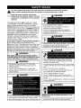 3
3
-
 4
4
-
 5
5
-
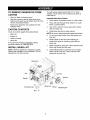 6
6
-
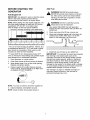 7
7
-
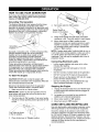 8
8
-
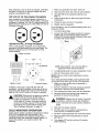 9
9
-
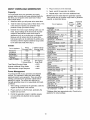 10
10
-
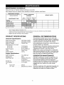 11
11
-
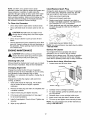 12
12
-
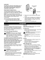 13
13
-
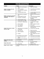 14
14
-
 15
15
-
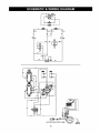 16
16
-
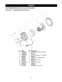 17
17
-
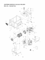 18
18
-
 19
19
-
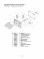 20
20
-
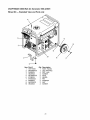 21
21
-
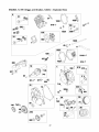 22
22
-
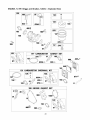 23
23
-
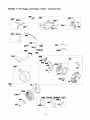 24
24
-
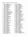 25
25
-
 26
26
-
 27
27
-
 28
28
-
 29
29
-
 30
30
-
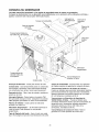 31
31
-
 32
32
-
 33
33
-
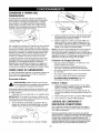 34
34
-
 35
35
-
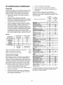 36
36
-
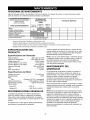 37
37
-
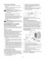 38
38
-
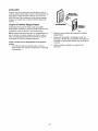 39
39
-
 40
40
-
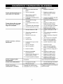 41
41
-
 42
42
-
 43
43
-
 44
44


Craftsman 580323601 El manual del propietario
- Categoría
- Generadores de poder
- Tipo
- El manual del propietario
en otros idiomas
- English: Craftsman 580323601 Owner's manual
Artículos relacionados
-
Craftsman 580326300 El manual del propietario
-
-
-
Simplicity 580.328301 El manual del propietario
-
-
-
Craftsman 580323602 El manual del propietario
-