
1
INSTALLATION
GUI
DE
GUÍA DE INSTALACIÓN
Capacity Herd capacity
Drinking height Net weight
7 gal
27 L
75 horses, 75 beef
75 horses, 75 beef
21.65 inches
550 mm
59.5 lbs
27 kg
Capacidad
Rebaño máx. Altura para beber Peso neto
7 galones
27 l
75 caballos, 75 reses
75 caballos, 75 reses
21,65 pulgadas
550 mm
59,5 libras
27 kg
English …………………………………………………………………………….…
2
Español ………………………………………………………………………………
20

2
Safety warnings
Caution!
Please read this installation guide carefully before you install the WaterPro2.
It is also a service guide for providing information about spare parts.
Warning!
The installation of your WaterPro2 must be performed with rigorous adherence to national and local plumbing and
electrical codes. Failure to install or maintain your unit to the code standards may result in personal injury, death or
loss of livestock.
Warranty registration
Please supply us with your details so that we can register your product and keep you informed of any important product updates.
• See more at livestock.tru-test.com/en-us/livestock-waterer-warranty-registration-form
• For details, see
Product warranty
on page 19.
© 2017-2020 Datamars Limited.
All product names and brand names in this document are trademarks or registered trademarks of their respective holders.
No part of this publication may be photocopied, reproduced, stored in a retrieval system, or transmitted in any form or by any
means, electronic, mechanical, photocopying, recording or otherwise without the prior written permission of Datamars Limited.
Product specifications may change without prior notice.
For more information on other quality Datamars brands and products, visit www.datamars.com
Datamars, Inc.
528 Grant Road
Mineral Wells
Texas 76067
UNITED STATES
Toll free: 800 874 8494
Fax: 940 327 8048
email: customerservices@datamars.com
Although the information presented in this product document is believed to be accurate and reliable, no responsibility for
inaccuracies can be assumed by Datamars Limited. Datamars Limited reserves the right at any time to change characteristics or
specifications without notice.
All trademarks with an * are neither owned by nor licensed to Datamars SA and belong to their respective owners.
180 0001-586 (833400) Issue 7, 10/2020

3
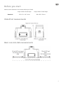
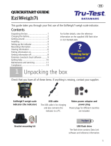
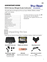
Before you start
Measure out the dimensions of the concrete slab that you will need.
Length x Width x Overall Height Length x Width x Overall Height
WaterPro2
39.2 x 22.1 x 28.7 inches 996 x 563 x 730 mm
WaterPro2 measurements
Basic concrete slab measurements

4
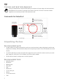
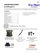
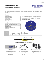
Concrete and tank hole alignment
Check your measurements to ensure that the opening on the bottom of the tank aligns with the thermal earth
tube placement in the concrete. The opening on the bottom of the tank is off center. Ensure that the water
supply lines are not touching the sides of the thermal earth tube.
Underneath the WaterPro2
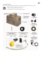
Unpacking the box
Recommended parts
• In colder climates, we strongly recommend the use of one or more thermal earth tubes to help keep the vertical water
supply line from freezing. The thermal earth tube(s) must be long enough to extend 1 foot (305 mm) below the normal
frost line.
• ½ inch NPT male fitting to connect the vertical water supply line to the ½ inch flex line inside the tank. If your vertical
water supply line is more than ½ inch in diameter, you will also need an adapter.
• 250 W immersion heater for heating water in the tank (optional).
Recommended tools
• Adjustable wrench
• Pipe wrench
• Measuring tape
• Utility knife
• Level
• Hammer drill
• ½ inch masonry bit
• Hammer
• ½ inch ratchet wrench
• Caulk

5
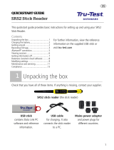
Included parts
Get to know the parts of the WaterPro2 before you install it. Contact us on 800 874 8494 if anything is missing.
• Images are indicative of shipped part and not shown to scale.
• * Jobe Rojo valve and valve mount are pre-installed.
• ** Shut-off valve and ½ inch flex line are connected together.

6
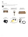
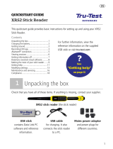
Spare parts
The parts below are available to order from your local Tru-Test WaterPro2 supplier.
Images are indicative of shipped part and not shown to scale.
Panel door Spare panel door fastener kit Float reservoir lid
880 0003-110 (832895P)
(excludes hardware and fastener kit)
880 0003-109 (832894P)
Eyebolt fastener and washer (2 pc)
880 0003-108 (832892P)
(excludes eyebolt fasteners)
Drain plug Valve and float De-icer (immersion heater)
880 0003-735 (831839P)
See overleaf for details of spare parts.
880 0003-431 (832381)

7
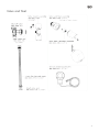
Valve and float

8
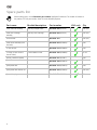
Spare parts list
When ordering parts, use the
Datamars part number
highlighted in bold text. The number in brackets is
the previous Tru-Test part number, shown for cross-reference purposes.
Part name Models/description Part number USA only Qty
Valve and float assembly Jobe Rojo compact valve
880 0003-588 (834478)
Each (kit)
Valve inner cartridge
assembly
Jobe Rojo inner cartridge
880 0003-589 (834479)
Each (kit)
Shut-off valve
880 0003-763
Each (kit)
Valve mount assembly (with
hex bolts)
880 0003-584 (832896P)
Each
½ inch flex line
880 0003-579 (832886P)
Each
3 x seals (for flex line and
shut-off valve)
3 seals needed in total.
880 0003-106 (832888P)
Pk of 2
De-icer (immersion heater)
880 0003-431 (832381)
- Each
Spare float reservoir lid
880 0003-108 (832892P)
Each
Spare panel door
880 0003-110 (832895P)
Each
Spare panel door fastener kit
880 0003-109 (832894P)
Each (kit)
Spare drain plug
880 0003-735 (831839)
Each

9
Installation
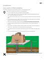
Cross-section of final installation
The WaterPro2 is designed to provide reliable fresh water to your livestock all year round.
When installing the WaterPro2 pay attention to the following areas:
• Choose a location where the tank will be sheltered from the elements.
• The vertical water supply line and the horizontal water supply line should all be installed to reach more
than 1 foot (305 mm) below the usual frost line.
• The concrete slab should have a 4 inch (102 mm) by 18 inch (457 mm) apron from the tank to the concre
te
edge.
• Ensure that the placement of the water and electric access hole in the concrete aligns with the anticipated
placement of the water and electric access cavity of the waterer.
• Make sure your vertical water supply line protrudes 10 inches (254 mm) above the concrete slab.
• The water supply line should be centered in the thermal earth tube (if using) to help discourage frost
formation.
• To be effective, the thermal earth tube(s)* must be installed to reach at least 1 foot (305 mm) below the
usual frost line.
*Note that more than one thermal earth tube may be required.
• Care should be taken to ensure the electric service below ground is installed outside of the thermal earth
tube.
• It is recommended to caulk the base of the tank to prevent moisture and wind penetration.
In addition to the shut-off valve located inside the unit, we strongly recommend that a second, external shut-off valve
be installed outside of the concrete.

10
Have you turned off the water?
Step 1: Preparing the site
a Choose a location that is easily accessible by livestock and sheltered from the elements.
b Check the measurements of your WaterPro2 against the size of the concrete slab you need. See
Concrete and tank hole
alignment
on page 4.
In the WaterPro2, the access cavity for the vertical water supply and electric supply is off center. Align the thermal earth
tube so that the vertical water supply is as close to the center of the tube as possible. Take care to ensure that the vertical
water supply line does not touch the sides of the thermal earth tube as this will cause the supply line to freeze. See
Concrete and tank hole alignment
on page 4.
Check that you have aligned the hole in the concrete with the access cavity under the WaterPro2.
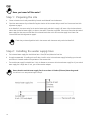
Step 2: Installing the water supply lines
a The horizontal water supply line should be at least 1 foot (305 mm) below the frost line.
b Strongly recommended: If installing a shut-off valve, install it on the horizontal water supply line leading up to the tank
and ensure it is located outside of the perimeter of the concrete slab.
c The vertical water supply line should be a ½ inch in diameter to connect to the horizontal water supply line. If your vertical
water supply line is larger than ½ inch, you will also need an adapter.
Ensure that the vertical water supply line is cut at least 10 inches (254 mm) above the ground.
You will cut it to a more precise length in Step 6.

11
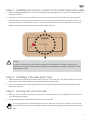
Step 3: Installing the electric service for the heat immersion cable
a If you are installing the WaterPro2 in an area that experiences freezing temperatures, you may wish to install an immersion
heater (part 832381).
b Arrange for your electrician to install the electric service around the same time you are installing the water supply lines.
c Install the electric service outside of the thermal earth tube on the horizontal side under one of the water reservoirs. Do
not install on either A or B side below as there is a risk that the electric service will not be located under the unit as the
diameter of the thermal earth tube almost spans the entire width of the unit.
Warning!
The electric service should only be installed by a qualified / certified electrician. The electric supply must run
outside of the thermal earth tube, be properly grounded, and be installed and maintained in accordance with all
applicable electric codes.
Step 4: Installing a thermal earth tube
a Install a thermal earth tube around the vertical water supply line. It must be at least 1 foot (305 mm) below the frost line.
Ensure that the vertical water supply line is centered within the thermal earth tube.
b If you are in a colder climate, we recommend an additional thermal earth tube be used to extend its length by at least
another foot (305 mm).
Step 5: Pouring the concrete slab
a Before you pour the concrete, check that you are using the correct measurements for your WaterPro2. See
Concrete and
tank hole alignment
on page 4.
b The thermal earth tube should be flush with the top of the concrete slab.
Do not pour concrete into the thermal earth tube or fill the space with dirt or any other material, as it will prevent
warm air below the frost line from circulating around the vertical water supply line, and will cause the water line to
freeze.

12
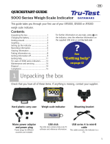
Critical step please follow these instructions carefully.
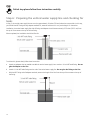
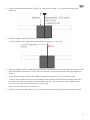
Step 6: Preparing the vertical water supply line and checking for
leaks
In Step 2, the vertical water supply line was cut to be approximately 10 inches (254 mm) above the concrete slab. In this step,
you will add the NPT fitting and any adapters needed first, measure and then cut it to a precise length. For the easiest
installation, the vertical water supply line with all fittings and adapters should measure exactly 8.75 inches (222.3 mm) from
the top of the concrete to the top of the last fitting.
When completed, the installation should look like this:
To achieve this, please closely follow these instructions:
a Attach any adapters that are needed to enable the vertical water supply line to receive a ½ inch NPT male fitting. Do not
glue the adapter to the line.
b Attach a ½ inch NPT male fitting onto the end of the vertical water supply line. Do not glue the fitting to the line.
c With the NPT fitting and all adapters attached, measure the length of the line from the top of the concrete to the top of
the fitting.

13
d Take the measurement and subtract 8.75 inches (222.3 mm) from this number. This is the amount of pipe you will
need to cut.
e Remove all adapters and fittings from the vertical water supply line.
f From the top down, mark the pipe with the measurement you need to cut. Cut the pipe.
g Attach any adapters and the ½ inch NPT fitting and re-measure. The distance from the top of the concrete to the top of the
NPT fitting should now measure 8.75 (222.3 mm) inches. Once this is confirmed, permanently attach your adapters and
fittings.
h Turn on the water supply to flush any dirt and debris through the water supply line. Turn off the water supply.
i To test for leaks throughout the entire system (including the valve), remove the valve and mount assembly, attach the ½
inch flex line to the shut-off valve and to the vertical water supply line. (The ½ inch flex line is pre-installed on some
units). Turn on the water and check for leaks. Turn off the water.
j Undo the shut-off valve from the ½ inch flex line.
k Slide the water supply insulation tube over the ½ inch flex line and vertical water supply line. Both should be insulated.

14
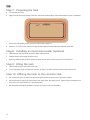
Step 7: Preparing the tank
a Turn the tank on its side.
b Apply the foam tape to the bottom of the tank, around the outside edge (in the recessed channel shown in red below).
c Lift the tank and carefully position it over the vertical water supply line.
d Attach the ½ inch flex line to the shut-off valve and then attach the valve and mount assembly to the tank.
Step 8: Installing an immersion heater (optional)
a Inside the tank, slide the 250 W immersion heater under the float.
b Feed the electric cord through the access cavity.
c With the panel door open, plug the immersion heater into the electric service, next to the ½ inch flex line.
Step 9: Filling the tank
a Insert the drain plugs on both sides of the tank.
b Turn on the water supply to fill the tank and check for leaks. If no leaks are found, attach the float reservoir lid.
Step 10: Affixing the tank to the concrete slab
a Drill ½ inch holes in the concrete using the mounting feet located on each corner of the tank as a guide.
b Insert anchor bolts in each hole. Place washers over anchor bolts, then apply the nut. Tighten the nut and repeat on all
four corners so that the WaterPro2 is securely mounted.
c We recommend caulking the perimeter of the tank to protect it from wind and debris.

15
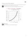
Pressure and flow capacity
You may need to install a pressure reducer on the vertical water supply line in hilly areas where the water pressure is affected.
Pressure values are measured at the valve inlet while the valve is running.
Pressures measured at other locations in the water line will be different from those at the valve inlet.
Metric measures
1 Bar = 100 Kilopascals which is 14.50 PSI (pounds per square inch).

16
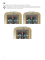
Using the shut-off valve as a pressure reducer
If high water pressure is an issue, the shut-off valve can be used to help reduce the flow of water into the valve.
We recommend the use of a pressure reducer in situations where water pressure exceeds 72.5 psi. (See
Pressure
and flow capacity
on page 15 if using a pressure valve).

17
Recommendations
Split fence measurements
The WaterPro2 can also be used to split two pastures or pens with a fence line separating the drinking area. This allows
livestock from both sides of the fence to have access to water.
Check that you have enough clearance between the float reservoir lid and fence so that you can remove the
lid to get to the valve and float assembly.
General maintenance
If you are not using your WaterPro2 for extended periods of time, drain the tank and shut off the main water supply to the tank.
Clean the tank weekly (at a minimum) to remove debris.
To facilitate easy cleaning:
• Use a stiff brush to clean the reservoir cavity.
• Remove the drain plug and flush.
• Turn the shut-off valve to the closed position or insert the drain plug into the hole in the float reservoir cavity.
• Repeat on the other side.
• The drain plug can be used to seal off one side of the tank if needed.

18
Troubleshooting
Symptom Possible cause/s Solution/s to check or action:
Water frozen in tank Water frozen in lines or
connections.
Vertical water supply line is properly insulated.
Tank bottom is sealed on concrete.
Livestock are drinking from the WaterPro2, if not, drain and refill
to recycle fresh water.
Vertical water supply line is centered within the thermal earth
tube.
Horizontal water supply line is 1 foot (51 mm) below the frost
line.
Low water flow Blockage or kinks in valves or
vertical water supply line.
Shut-off valve not set correctly.
Vertical water supply line is free from kinks.
Valve and float assembly has no blockages.
Shut-off valve is set to the open position. See the images of shut-
off valve positions in
Using the shut-off valve as a pressure
reducer
on page 15.
Check water pressure with a pressure gauge.
Water dri
pping out of
valve
Seals may need replacing. Check valve o-rings and shut off valve gasket.
Check that the valve connections have been tightened.
Valve and float assembly is clear of debris.
The shut-off valve is set to the open position. See the images of
shut-off valve positions in
Using the shut-off valve as a pressure
reducer
on page 15.
Valve does not shut
off
Worn inner cartridge assembly. Replace valve and inner cartridge assembly.
Check inner cartridge assembly and o-rings. See
Pressure and
flow capacity
on page 15.
Drain plugs leak Worn drain plug or drain plug
screw not tightened.
Replace drain plug.
Tighten drain plug.

19
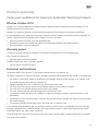
Product warranty
Terms and conditions for Livestock Automatic Watering Products
Effective October 2019
Datamars, Inc.’s warranty obligations for Livestock Automatic Watering products manufactured by or for Datamars, Inc. are
limited to the terms set out in this policy.
Datamars, Inc. warrants its products to be free of defective materials and workmanship for the periods outlined below.
If a warranted defect occurs, please return the product along with proof of purchase to the place of purchase. If Datamars, Inc.
receives a valid claim within the Warranty Period, Datamars, Inc. will, at its option:
• Repair the product at no charge, using new replacement parts.
• Exchange the product with a product that is new or has functionality equivalent to the original product; or
• Refund the product’s original purchase price.
Warranty period
The period of warranty (warranty period) begins at original date of purchase and runs for the following terms:
Base, Top and Float Reservoir Lid
• Eight years against manufacturing defect.
Component Parts (floats, valves, drain plugs, fasteners)
• One year against manufacturing defect.
Exclusions and limitations
This warranty applies only to genuine Tru-Test products manufactured by or for Datamars, Inc.
The liability of Datamars, Inc. under this warranty is excluded to the extent that any defect has been caused or contributed to by:
• Any accident, contamination, tampering, modification, wilful damage, improper storage, improper use or negligent act of,
or by omission by, any person other than Datamars, Inc.;
• Improper installation of the unit, or deterioration of the base upon which it rests;
• The use of the unit for any other purpose than providing a stationary source of water for livestock;
• The use of the unit for any other purpose than for which it was intended;
• The use of anything other than the original equipment or manufacturer’s parts;
• Any damage to the unit caused by storm, landslide, fire, lightning, earthquake, tornado or any other naturally occurring
phenomenon;
• Any damage to the unit caused by vermin or other pest, and any undermining of the base upon which the unit sits through
any cause whatsoever;
• This warranty specifically excludes the unit color, which may fade or change over time.
To the maximum extent permitted by law, this warranty is exclusive, personal to you, non-transferable, and in lieu of all other
warranties, representations or conditions relating to this product (whether express or implied and whenever arising) whether
originating by statute, law, trade, custom or otherwise.
The product warranty is only valid in the original country of purchase. Any claims made in another country may incur full repair
costs at the owner’s expense.

20
Ver Advertencias de seguridad
¡Advertencia!
Debe leer cuidadosamente esta guía antes de instalar el WaterPro2.
¡Advertencia!
La instalación del WaterPro2 debe realizarse siguiendo cuidadosamente la normativa nacional
y local relativa a fontanería y artefactos eléctricos. Si la instalación o el mantenimiento de esta unidad no se
ejecuta según la normativa, podría sufrir lesiones personales, la muerte o la pérdida de animales.
Registro de la garantía
Envíenos sus datos para poder registrar su producto y mantenerlo informado de cualquier actualización importante.
• Más información en livestock.tru-test.com/en-us/livestock-waterer-warranty-registration-form
• Para detalles sobre la garantía del producto, consulte
la página 36.
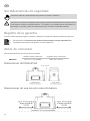
Antes de comenzar
Mida las dimensiones de la losa de concreto que necesitará.
Longitud x Ancho x Altura total Longitud x Ancho x Altura total
WaterPro2
39,2 x 22,1 x 28,7 pulgadas 996 x 563 x 730 mm
Dimensiones del WaterPro2
Dimensiones de una losa de concreto básica

21
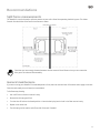
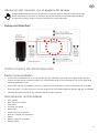
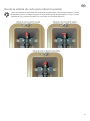
Alineación del concreto con el agujero del tanque
Revise las medidas para garantizar que la apertura en el fondo del tanque se alinea con la ubicación del tubo
térmico subterráneo en el concreto. La apertura en el fondo del tanque no está centrada. Asegúrese de que
las tuberías de suministro de agua no tocan los lados del tubo térmico subterráneo.
Debajo del WaterPro2
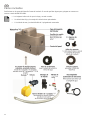
Instrucciones de desempacado
Partes recomendadas
• En climas fríos, recomendamos el uso de uno más tubos térmicos subterráneos para evitar que la tubería de agua vertical se
congele. Los tubos térmicos subterráneos deben ser lo suficientemente largos como para extenderse 305 mm por debajo de la
línea de congelamiento normal.
• Conector NPT macho de ½ pulgada para conectar la tubería de suministro vertical de agua a la tubería flexible de ½ pulgada
dentro del tanque. Si su tubería de suministro vertical de agua es de más de media pulgada de diámetro, debe usar un adaptador.
• Calentador de inmersión de 250 W, para calentar el agua en el tanque (opcional).
Herramientas recomendadas
• Llave ajustable
• Llave inglesa / para tuberías
• Cinta métrica
• Cuchilla de uso general
• Nivel de agua
• Taladro con función de martillo
• Broca de ½ pulgada para mampostería
• Martillo
• Llave de trinquete de ½ pulgada
• Sellador (masilla)

22
Partes incluidas
Familiarícese con las partes del WaterPro2 antes de instalarlo. En caso de que falte alguna parte, póngase en contacto con
nosotros a través del 800 874 8494.
• Las imágenes indican solo lo que se incluye y no están a escala.
• * La válvula Jobe Rojo y el montaje de la válvula vienen preinstaladas.
• ** La válvula de corte y la tubería flexible de ½ pulgada están conectadas.

23
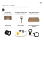
Piezas de repuesto
Las piezas a continuación están disponibles en su distribuidor local Tru-Test de WaterPro2.
Las imágenes indican solo lo que se incluye y no están a escala.
Puerta del panel Kit de ajuste de la puerta del panel Tapa del depósito del flotador
880 0003-110 (832895P)
Excluye el herraje y el kit de ajuste
880 0003-109 (832894P)
Tornillo de argolla y arandela (2 piezas)
880 0003-108 (832892P)
Excluye los tornillos de argolla
Tapón de drenaje Válvula y flotador Descongelador (calentador de
inmersión)
880 0003-735 (831839P)
Consulte al dorso para más información
acerca de las piezas de repuesto.
880 0003-431 (832381)

24
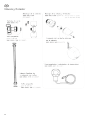
Válvula y flotador

25
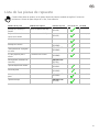
Lista de las piezas de repuesto
Cuando solicite piezas de repuesto, use el número de parte de Datamars resaltado en negrillas. El número en
corchetes es el número de parte antiguo de Tru-Test, como referencia.
Nombre de la parte Modelos/Descripción Número de parte Sólo en EE.UU.
Cantidad
Montaje de la válvula y el
flotador
Válvula compacta Jobe Rojo
880 0003-588
(834478)
Cada uno (kit)
Conjunto del cartucho
internode la válvula
Cartucho interno Jobe Rojo
880 0003-589
(834479)
Cada uno (kit)
Válvula de corte
880 0003-763
Cada uno (kit)
Montaje de la válvula
880 0003-584
(832896P)
Cada uno
Tubería flexible de ½ pulgada
con sellos
880 0003-579
(832886P)
Cada uno
3 x Sello pequeño para la
válvula
Se necesitan tres en total.
880 0003-106
(832888P)
Pack de 2
Descongelador (calentador de
inmersión)
880 0003-431
(832381)
-
Cada uno
Tapa del depósito del flotador
880 0003-108
(832892P
Cada uno
Puerta del panel
880 0003-110
(832895P)
Cada uno
Kit de ajuste de la puerta del
panel
880 0003-109
(832894P)
Cada uno (kit)
Tapón de drenaje
880 0003-735
(831839)
Cada uno

26
Instalación
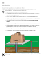
Corte transversal de la instalación final
El WaterPro2 está diseñado para suministrar agua fresca a sus animales de manera confiable durante todo el año.
Al instalar el WaterPro2, preste especial atención a las siguientes áreas:
• Elija una ubicación donde el tanque esté lo más resguardado del clima.
• Las tuberías de suministro vertical y horizontal de agua deben instalarse de forma que superen los 305 mm por
debajo de la línea de congelamiento usual.
• La losa de concreto debe tener al menos 102 mm de espesor y 457 mm del tanque al borde del concreto.
• Asegúrese de que el agujero de acceso eléctrico y de agua en el concreto esté alineado con el lugar donde desea
ubicar la unidad y sus respectivas cavidades de agua y electricidad.
• Compruebe que la tubería de suministro vertical de agua sobresale al menos 254 mm sobre la losa de
concreto
• La tubería de suministro de agua debe estar centrada en el tubo térmico subterráneo para evitar la formación de
escarcha.
• Para que sean efectivos, los tubos térmicos subterráneos deben extenderse al menos 305 mm por debajo de la
línea de congelamiento normal.
*Nota: Es posible que necesite más de un tubo térmico subterráneo.
• Debe tomar las precauciones necesarias para garantizar que el suministro eléctrico bajo tierra se instale fuera del
tubo térmico subterráneo.
• Se recomienda usar sellador en la base del tanque para evitar que penetre la humedad y el viento.
Además de la válvula de corte dentro de la unidad, recomendamos que se instale una segunda, externa y alejada de la
losa de concreto.

27
¿Ha cerrado la llave de paso de agua?
Paso 1: Preparación del sitio
a Elija una ubicación que los animales puedan acceder con facilidad y que cuente con protección del clima.
b Revise las dimensiones del WaterPro2 en relación con el tamaño de la losa de concreto que necesita. Consulte
Alineación del
concreto con el agujero del tanque
en la página 21.
En el WaterPro2, la cavidad de acceso del suministro vertical de agua y del suministro eléctrico se encuentra fuera del centro.
Alinee el tubo térmico subterráneo de forma que el suministro vertical de agua esté lo más cercano posible al centro del tubo.
Asegúrese de que la línea de suministro vertical de agua no toque los laterales del tubo térmico, ya que si lo hace se congelará el
suministro de agua. Consulte
Alineación del concreto con el agujero del tanque
en la página 21.
Revise que haya quedado alineado el agujero en el concreto con la cavidad de acceso bajo el WaterPro2.
Paso 2: Instalación de las tuberías de suministro de agua
a La tubería de suministro horizontal de agua debe ubicarse al menos 305 mm por debajo de la línea de congelamiento.
b Se recomienda encarecidamente que, si instala una válvula de corte, la instale en la tubería de suministro horizontal de agua que
vaya al tanque y asegúrese de que esté ubicada fuera del perímetro de la losa de concreto.
c La tubería de suministro vertical de agua debe ser de ½ pulgada de diámetro para así conectarse a la de suministro horizontal de
agua. Si su tubería de suministro vertical de agua es de más de media pulgada de diámetro, debe usar un adaptador.
Asegúrese de que la tubería de suministro vertical de agua se corte a al menos 254 mm por
encima de la superficie. Luego ajustará su longitud con mayor precisión en el Paso 6.

28
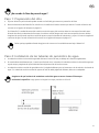
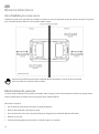
Paso 3: Instalación del suministro eléctrico para el cable del
calentador de inmersión
a Si instala el WaterPro2 es un área donde se producen temperaturas de congelamiento, es posible que quiera instalar un
calentador de inmersión (número de pieza 832381).
b Coordine con su electricista para que instale el suministro eléctrico alrededor del mismo momento que instale las tuberías de
suministro de agua.
c Instale el servicio de suministro eléctrico por fuera del tubo térmico subterráneo en el lado horizontal y debajo de uno de los
depósitos de agua. No instale a los lados A o B debajo, ya que corre el riesgo de que el suministro eléctrico no quedé ubicado
debajo de la unidad debido a que el diámetro del tubo térmico subterráneo es casi tan ancho como la unidad.
¡Advertencia!
El suministro eléctrico solo debe instalarse por un electricista calificado o certificado. El suministro
eléctrico debe estar alejado del tubo térmico subterráneo, contar con conexión a tierra y debe instalarse y
mantenerse siguiendo todas las normas eléctricas aplicables.
Paso 4: Instalación del tubo térmico subterráneo
a Instale el tubo térmico subterráneo de forma que envuelva la tubería de suministro vertical de agua. Debe estar a al menos 305
mm por debajo de la línea de congelamiento. Asegúrese de que la tubería de suministro vertical de agua está centrada en
relación al tubo térmico subterráneo.
b Si se encuentra en un clima muy frío, recomendamos usar un tubo térmico subterráneo adicional para extender su longitud un
mínimo de 305 mm más.
Paso 5: Vertido de la losa de concreto
a Antes de colocar el concreto, compruebe que está usando las medidas correctas de su WaterPro2. Consulte
Alineación del
concreto con el agujero del tanque
en la página 21.
b El tubo térmico subterráneo debe estar nivelado con la parte superior de la losa de concreto.
No vierta concreto en el tubo térmico subterráneo o llene el espacio con tierra o cualquier otro material, ya que
evitará que el aire caliente por debajo de la línea de congelamiento circule alrededor de la tubería de suministro de
agua vertical y, por ende, el agua se congelará.

29
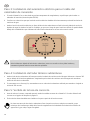
Paso muy importante: Siga estas instrucciones cuidadosamente.
Paso 6: Preparación de la tubería de suministro vertical de agua y
verificación de fugas
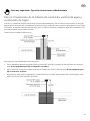
En el Paso 2, la tubería de suministro vertical de agua se cortó aproximadamente a 254 mm sobre la losa de concreto. En este paso,
agregará primero el conector NPT y los adaptares que pudiera necesitar, medirá de nuevo y cortará a la longitud precisa. Para facilitar
la instalación, la tubería de suministro vertical de agua, junto con todos los conectores y adaptadores, debe medir exactamente 222,3
mm desde el tope del concreto hasta su extremo.
Cuando finalice, la instalación debe verse así:
Para lograr esto, siga cuidadosamente estas instrucciones:
a Fije los adaptadores necesarios para poder colocar el conector NPT macho de ½ pulgada a la tubería de suministro vertical de
agua. No use pegamento para fijar el adaptador a la tubería.
b Fije un conector NPT macho de ½ pulgada al extremo de la tubería de suministro vertical de agua. No use pegamento para
fijar el conector a la tubería.
c Después de que tenga todos los adaptadores y el conector NPT fijos a la tubería, mida la distancia de la tubería desde la parte
superior del concreto hasta el extremo del conector.

30
d Tome esta medida y réstele 222,3 mm. Esta es la longitud de la tubería que debe cortar.
e Retire todos los adaptadores y conectores de la tubería de suministro vertical de agua.
f De la parte superior hacia abajo, marque la tubería con la medida debe cortar. Corte la tubería.
g Fije los adaptadores y el conector de ½ pulgada y mida de nuevo. La distancia del tope del concreto hasta el extremo del conector
NPT debe medir exactamente 222,3 mm. Una vez que confirme esto, fije permanentemente sus adaptadores y el conector.
h Abra la llave de paso de agua para purgar cualquier sedimento o suciedad de la tubería. Cierre la llave de paso de agua.
i Para verificar si hay fugas en el sistema entero (incluyendo la válvula), retire el montaje de válvula y fije la tubería flexible de ½
pulgada a la válvula de corte y a la tubería de suministro vertical de agua. (La tubería flexible de ½ pulgada viene preinstalada en
algunos modelos). Abra la llave de paso de agua y revise si hay fugas. Cierre la llave de paso de agua.
j Desconecte la válvula de corte de la tubería flexible de ½ pulgada.
k Deslice el tubo de aislamiento sobre la tubería flexible de ½ pulgada y la tubería de suministro vertical de agua. Ambos deben
estar aislados.

31
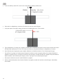
Paso 7: Preparación del tanque
a Voltee el tanque sobre un costado.
b Aplique la cinta de espuma al fondo del tanque, alrededor del borde exterior (en el canal encastrado, que se muestra en rojo a
continuación).
c Levante el tanque y ubíquelo con cuidado sobre la tubería de suministro vertical de agua.
d Conecte la tubería flexible de ½ pulgada a la válvula de corte y luego el montaje de válvula al tanque.
Paso 8: Instalación del calentador de inmersión (opcional)
a Dentro del tanque, deslice el calentador de inmersión de 250 W debajo del flotador.
b Pase el cable eléctrico a través de la cavidad de acceso.
c Con la puerta del panel abierta, enchufe el calentador de inmersión al suministro eléctrico, junto a la tubería flexible de ½
pulgada.
Paso 9: Llenado del tanque
a Inserte los tapones de drenaje en ambos lados del tanque.
b Abra la llave de paso del suministro de agua para llenar el tanque; revise que no haya fugas. Si no encuentra fugas, fije la tapa
del flotador.
Paso 10: Fijado del tanque a la losa de concreto
a Use un taladro para abrir agujeros de ½ pulgada (1,27 cm) en el concreto, usando los pies de montaje en cada esquina del
tanque como guía.
b Inserte los pernos de ancla en cada agujero. Coloque arandelas sobre los pernos, y luego las tuercas. Apriete las tuercas y luego
repita en las cuatro esquinas, de forma que el WaterPro2 quede fijo.
c Recomendamos usar sellador alrededor del perímetro del tanque para protegerlo del viento y los desperdicios.

32
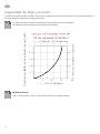
Capacidad de flujo y presión
Es posible que tenga que instalar un reductor de presión en la tubería de suministro vertical de agua en caso de que esté ubicado en
una zona montañosa, donde la presión del agua sea mayor.
Los valores de presión se miden en la entrada de la válvula cuando está en funcionamiento.
Las mediciones en otros lugares de la línea de agua serán diferentes.
Mediciones métricas
1 Bar = 100 kilopascales, lo que es 14,50 psi (libra de fuerza por pulgada cuadrada ).

33
Uso de la válvula de corte para reducir la presión
Si tiene mucha presión de agua, puede usar la válvula de corte para reducir el flujo de agua que pasa a la unidad.
Recomendamos que use un reductor de presión en casos donde la presión de agua exceda los 72,5 psi. (consulte
Capacidad de flujo y presión
en la página 32 en caso de que use una válvula de presión).

34
Recomendaciones
Uso dividido por una cerca
El WaterPro2 puede usarse para dividir dos pastizales o corrales con una cerca que separe el área de suministro de agua. Esto permite
que los animales de ambos lados de la cerca puedan acceder al agua.
Revise que haya suficiente espacio entre la tapa del depósito del flotador y la cerca, de forma que pueda
retirarla y acceder al montaje de válvula y flotador.
Mantenimiento general
Si no está usando el WaterPro2 por periodos prolongados, drene el tanque y cierre la llave de paso de suministro de agua al tanque.
Limpie el tanque todas las semanas (como mínimo) para retirar cualquier desecho.
Para facilitar la limpieza:
• Use un cepillo de cerdas duras para limpiar la cavidad del depósito.
• Retire el tapón de drenaje y descargue con agua.
• Cierre la válvula de corte o inserte el tapón de drenaje en el agujero de la cavidad del depósito del flotador.
• Repita en el otro lado.
• El tapón de drenaje puede usarse para sellar un lado del tanque si es necesario.

35
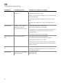
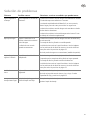
Solución de problemas
Síntoma Posibles causas Soluciones a revisar o medidas que puede tomar:
Agua congelada en
el tanque
Agua congelada en las tuberías o
conexiones.
La tubería de suministro vertical de agua está debidamente aislada.
El fondo del tanque está sellado en el concreto.
Los animales están bebiendo del WaterPro2; en caso contrario,
drene el agua y llene de nuevo para reciclar con agua fresca.
La tubería de suministro vertical de agua está centrada en relación
al tubo térmico subterráneo.
La tubería de suministro horizontal de agua está al menos 51 mm
por debajo de la línea de congelamiento.
Bajo flujo de agua Bloqueo u obstáculos en las
válvulas o tubería de suministro
vertical de agua.
La válvula de corte no está
ajustada correctamente.
La tubería de suministro vertical de agua está libre de obstáculos y
no está retorcida.
El montaje de válvula y flotador no está bloqueado.
La válvula de cierre está en la posición abierta. Vea las imágenes
con las posiciones de la válvula de corte en
Uso de la válvula de
corte para reducir la presión
en la página 32.
Revise la presión de agua con un manómetro (medidor de presión).
Hay una fuga de
agua en la válvula
Es posible que los sellos deban
reemplazarse.
Revise los o-rings de la válvula y la junta de la válvula de corte.
Compruebe que las conexiones de la válvula se hayan apretado.
El montaje de válvula y flotador está libre de desechos.
La válvula de cierre está en la posición abierta. Vea las imágenes
con las posiciones de la válvula de corte en
Uso de la válvula de
corte para reducir la presión
en la página 32.
La válvula no se
cierra
Conjunto del cartucho interno
desgastado.
Reemplace la válvula y el conjunto del cartucho interno.
Revise el conjunto del cartucho interno y los o-rings. Consulte
Capacidad de flujo y presión
en la página 32.
Los tapones de
drenaje tienen fugas
Tapón de drenaje desgastado o el
tornillo del tapón está flojo.
Reemplace el tapón de drenaje.
Apriete el tapón de drenaje.

36
Garantía del producto
Términos y condiciones para Productos de suministro de agua
automáticos para animales de crianza
En vigencia a partir de octubre de 2019
Las responsabilidades de garantía de Datamars, Inc. para Productos de suministro de agua automáticos para animales de crianza
fabricados por o para Datamars, Inc. están limitadas a los términos en la presente política.
Datamars, Inc. garantiza que sus productos están libres de defectos en materiales y mano de obra durante los periodos descritos a
continuación.
Si ocurre un defecto cubierto por la garantía, devuelva el producto junto al comprobante de la compra al lugar de la compra. Si
Datamars, Inc. recibe una reclamación válida dentro del período de la garantía, Datamars, Inc. podrá según su criterio:
• Reparar el producto sin carga alguna, usando piezas de repuesto nuevas.
• Cambiar el producto por un producto nuevo o un producto equivalente al producto original o
• Reembolsar el precio de compra original del producto.
Periodo de garantía
El periodo de garantía ("Periodo de garantía") comienza en la fecha original de compra y continúa según los siguientes términos:
Base, parte superior y tapa del depósito del flotador
• Ocho años, por defectos de fabricación.
Partes y componentes (flotador, válvulas, tapones de drenaje y tornillos)
• Un año, por defectos de fabricación.
Exclusiones y limitaciones
Esta garantía aplica solo a los productos originales de Tru-Test, fabricados por o para Datamars, Inc.
Las responsabilidades de Datamars, Inc. bajo esta garantía están excluidas en la medida en que cualquier defecto haya sido causado o
por contribución de:
• Accidentes, contaminación, alteración, modificación, daño deliberado, almacenamiento inadecuado, uso incorrecto o negligencia
u omisión por parte de cualquier otra persona a parte de Datamars, Inc.;
• Instalación inadecuada de la unidad, o deterioro de la base donde descansa;
• El uso de la unidad para cualquier otro propósito que el de ofrecer una fuente de agua estacionaria para animales;
• El uso de la unidad para cualquier otro fin que el previsto;
• El uso de cualquier otra parte o pieza diferente a la original o del fabricante;
• Cualquier daño que haya sufrido la unidad a causa de tormenta, deslave, fuego, relámpago, terremoto, tornado o cualquier otro
fenómeno natural;
• Cualquier daño que haya sufrido la unidad a causa de plagas o alimañas, así como cualquier socavación de la base donde
descansa la unidad, sin importar la causa.
• Esta garantía excluye específicamente el color de la unidad, que podrá desteñirse o cambiar según pasa el tiempo-
Hasta la máxima extensión permitida por la ley, esta garantía es exclusiva, personal para Ud., intransferible y reemplaza todas las
demás garantías, representaciones o condiciones relativas a este producto (de manera expresa o implicada cada vez que surge) que
tienen su origen en estatutos, leyes, comercio, uso u otro.
La garantía de este producto solo es válida en el país donde se compró. Los reclamos hechos en otros países podrían incurrir en gastos
de reparación a expensas del propietario.
-
 1
1
-
 2
2
-
 3
3
-
 4
4
-
 5
5
-
 6
6
-
 7
7
-
 8
8
-
 9
9
-
 10
10
-
 11
11
-
 12
12
-
 13
13
-
 14
14
-
 15
15
-
 16
16
-
 17
17
-
 18
18
-
 19
19
-
 20
20
-
 21
21
-
 22
22
-
 23
23
-
 24
24
-
 25
25
-
 26
26
-
 27
27
-
 28
28
-
 29
29
-
 30
30
-
 31
31
-
 32
32
-
 33
33
-
 34
34
-
 35
35
-
 36
36


En otros idiomas
Documentos relacionados
-
 Tru-Test WaterWell™ 2 and WaterWell™ 4 Guía de instalación
-
 Tru-Test EziWeigh7i Guía de inicio rápido
-
 Tru-Test EziWeigh7i Guía de inicio rápido
-
Tru-Test S3 Indicator Guía de inicio rápido
-
 Tru-Test JR5000 ID5000 XR5000 Guía de inicio rápido
-
Tru-Test XRP2 Panel Reader and Antenna Guía de inicio rápido
-
 Tru-Test JR5000 ID5000 XR5000 Guía de inicio rápido
-
 Tru-Test SRS2 Guía de inicio rápido
-
 Tru-Test SRS2 Stick Reader Guía de inicio rápido
-
 Tru-Test XRS2 Stick Reader Guía de inicio rápido


