La página se está cargando...

INSTALLERS, CARPENTERS, CONTRACTORS
- Read all warning notes. Warning notes contain important
safetytips.
- In order to assure safe use of the attic ladder, proceed
according to the installationinstruction.
- The attic ladder is not safe to use, unless it is completely
installed according to the following instructions.
2 31
“FAKRO” and the FAKRO logo are registered trademarks of FAKRO Group.
All specifications are subject to change without prior notice.
©2009 FAKRO GROUP
FAKRO AMERICA, L.L.C.
311 W. Laura Dr
Addison, IL 60101, USA
tel. (630) 543-1010
e-mail: [email protected]
www.fakrousa.com
www.fakro.com
http://shop.fakrousa.com
SKYWIN
77 Woodland Ave
Chatham ON N7L 2S5, CANADA
tel. (519) 352-6587
e-mail: [email protected]
www.fakro.ca
www.atticstairsus.com
ES
Fig.18. Longitud “S” del travesaño longitudinal entre los Travesaños.
Fig.19.
Instalación de TravesañosLongitudinales
Travesaño
Puntillas
Travesaño
Longitudinal
Paso 1
Mida la distancia “S” del travesaño longitudinal entre los
travesaños (Figura 18). La medida deberá ser perpendicular a la
del travesaño.
Paso 2
Corte un travesaño longitudinal con esa distancia. Utilice madera
similar al tamaño de las vigas existentes en el techo.
Paso 3
Si las vigas no forman los otros 2 lados del marco, entonces
necesita instalar un travesaño longitudinal con la misma distancia
del primero. Observe que únicamente necesita un travesaño
longitudinal, como se muestra en la figura 18 ya que la viga del
techo crea uno de los lados del marco.
Paso 4
Coloque el travesaño(s) longitudinal a lo largo del lado(s) sin
enmarcar de la abertura preliminar (Figura 19). Las dimensiones
interiores del marco deben ser igual a las de la abertura preliminar
que se muestra en la tabla 2 (Ver página 5).
Paso 5
Para colocar el travesaño(s) longitudinal a los travesaños debe
utilizar clavos que sean lo suficientemente largos para qué
atraviesen ambos maderos y penetre el travesaño longitudinal al
menos 1 pulgada. En la mayoría de los casos deberán ser clavos
de 20d y con un largor de 4”. Cuadre el travesaño longitudinal y
coloque 3 clavos en cada extremo traspasando los travesaños
dobles. Ambas medidas no deben diferir en más de 1/8 para
considerarse igual. (Figura 19).

3
Table of content
I. Important issues to consider . . . . . . . . . . . . . . . . . . . . . . . . . . . . . . . . . . . . . . . . . . . . . . . . . . . . . . .pages 4
- are you able to install attic ladder? . . . . . . . . . . . . . . . . . . . . . . . . . . . . . . . . . . . . . . . . . . . . . . . .p
ages 4
- will attic ladder satisfy your expectations? . . . . . . . . . . . . . . . . . . . . . . . . . . . . . . . . . . . . . . . . . .p
ages 4
- does the construction of your ceiling enables installation of the attic ladder? . . . . . . . . . . . . . .p
ages 4
II. Your package should contain . . . . . . . . . . . . . . . . . . . . . . . . . . . . . . . . . . . . . . . . . . . . . . . . . . . . .p
ages 5
III. Required manpower, tools and materials . . . . . . . . . . . . . . . . . . . . . . . . . . . . . . . . . . . . . . . . . . . .pages 5
IV. Finding a suitable locations for installation . . . . . . . . . . . . . . . . . . . . . . . . . . . . . . . . . . . . . . . . . . .pages 6
V. Cutting a hole in the ceiling . . . . . . . . . . . . . . . . . . . . . . . . . . . . . . . . . . . . . . . . . . . . . . . . . . . . . . .pages 7
VI. Cutting the ceiling joists . . . . . . . . . . . . . . . . . . . . . . . . . . . . . . . . . . . . . . . . . . . . . . . . . . . . . . . . . .pages 8
VII. Framing the installation opening . . . . . . . . . . . . . . . . . . . . . . . . . . . . . . . . . . . . . . . . . . . . . . . . . . .pages 9
- installing the single headers . . . . . . . . . . . . . . . . . . . . . . . . . . . . . . . . . . . . . . . . . . . . . . . . . . . . . .pages 9
- double headers . . . . . . . . . . . . . . . . . . . . . . . . . . . . . . . . . . . . . . . . . . . . . . . . . . . . . . . . . . . . . . .pages 10
- installation of stringers . . . . . . . . . . . . . . . . . . . . . . . . . . . . . . . . . . . . . . . . . . . . . . . . . . . . . . . . . .pages 11
EN
30
Instalaciónde Travesaños Dobles
Paso 1
Mida la distancia “H” del travesaño entre las vigas del techo sin
cortar (Figura 15).
Paso 2
Corte 4 travesaños con esta longitud. Para ese propósito utilice
madera similar al tamaño de las vigas existentes.
Paso 3
Coloque un travesaño en un extremo de la viga cortada (Figura
16). Este debe encajar justamente entre las vigas. Si es necesario
utilice un martillo para colocar el travesaño en el lugar apropiado.
Paso 4
Cuadre el travesaño a una de las vigas y coloque 3 clavos (16d)
en ambos extremos y en la viga cortada (Figura 16).
Paso 5
Coloque el segundo travesaño enfrente del primero y clávelo
(Figura 17).
Paso 6
Repita los pasos 3-5 para instalar los travesaños al extremo
opuesto de la abertura.
Paso 7
Para enmarcar el otro lado(s) de la abertura preliminar, vaya a
“Instalación de Travesaños Longitudinales” en la página siguiente.
H
Fig. 15. Mida la distancia “H” del travesaño entre las vigas del techo
No cortadas.
Fig.16.
Fig.17.
Viga Cortada
PrimerTravesaño
Puntillas
Viga Cortada
SecundoTravesaño
Puntillas
Vigas No-Cortadas

4
Before you start any work read carefully all instructions, in order to
make sure that you have a proper spot for installation and tools.
Are youable to install attic ladder?
In order to install this attic ladder, you need to know how to cut
wood and use framing square. Not being able to do the above,
installation of this product should be done by a professional installer
(refer to yellow pages).
Will attic ladder satisfyyour expectations?
The attic ladder has been designed only for home use. Installation
of this product in commercial buildings can be obstructing to existing
building codes. Before installation of this product consult with Fire
Department or your local building inspector.
The attic ladder has been designed to be installed in room where
the ceiling height is in the range described on the packaging. This
product should not be installed if the ceiling height does not fit in the
range described on the product's label. Modifications of the attic
ladder can be dangerous.
Doesthe constructionofyourceilingenablesinstallationofthe attic
ladder?
The attic ladder can be installed in buildings with typical wood
framed ceiling (Figure1). You should never cut any of the
constructing elements of the ceiling without prior consultation with
an architect (refer to yellow pages).
The attic ladder should not be installed in chosen spot if there is one
of the following:
— air ducts
— metal constructions
— cement ceiling
— drop ceiling
If your ceiling has one of the above elements you can not install the
attic ladder. In this case you should seek professional help.
The following instruction describes the installation method of the
attic ladder.
WARNING! DO NOT CUT THIS TYPE OF CONSTRUCTION
(FIG. 2, 3) WITHOUT PRIOR CONSULTATION WITH AN
ARCHITECT.
Fig.3. Truss roof frame.
Fig.1. Typical roof construction
Fig.2. Typical construction of the roof with braces connected to the ceil-
ing joists.
I. IMPORTANT ISSUES TO CONSIDER
rafter
ceiling joist
rafter
ceiling joist
brace
rafter
ceiling joist
29
ES
Antesde Proceder:
La distancia entre las vigas deberá ser la misma al ancho de la abertura de instalación. Todas las vigas cortadas deberán ser unidas a las vigas
que no han sido cortadas.
ADVERTENCIA!
Por su propia seguridad tenga en cuenta que todos los elementos peligrosos pueden estar sobre su cabeza. No se siente sobre el techo. Este
no está diseñado para soportar peso, únicamente las vigas sostendrán el peso. Para hacer un lugar de trabajo, coloque varios maderos que
crucen las vigas del techo.
VII. ENMARCADO DE LA ABERTURA PRELIMINAR
Instalando el Enmarcado
Si una de las vigas fue cortada proceda a la sección de
“Instalación de Travesaños Sencillos”.
Si una o más vigas fueron cortadas proceda a la sección de
“Instalación de Travesaños Dobles” en la página 8.
-Instalaciónde travesañosSencillos
Paso 1
Medir la distancia entre las vigas del techo. (Figura 12).
Paso 2
Corte 2 travesaños con esta longitud. Utilice madera del tamaño de
la viga.
Paso 3
Coloque un travesaño en uno de los extremos de la abertura
(Figura 13). El travesaño, deberá de encajar ajustadamente entre
las vigas. Si es necesario utilice un martillo para colocar el
travesaño.
Paso 4
Alinear el travesaño en un ángulo de 90° con la viga y coloque 3
clavos (16) en cada extremo.
Paso 5
Coloque el segundo travesaño a 31”,47” o 54” de distancia del
primero, repita el paso 4 (Figura 14). La distancia entre los
travesaños depende del modelo de la escalera.
Paso 6
El marco deberá tener cuatro lados, los travesaños conforman 2
de ellos. Si las vigas del techo están colocadas como los otros 2
lados, verifique el ángulo midiendo las diagonales. Ambas medidas
deberán estar dentro de 1/8” para considerarlas iguales.
Si las vigas del techo no conforman los otros 2 lados del marco,
deberá instalar uno o 2 piezas de madera adicionales para
enmarcar el otro extremo de la abertura preliminar. Proceda a la
sección “Instalación de Travesaños Longitudinales” en la pagina
9.
Fig.12.P. Mida la longitud “H” del travesaño entre las vigas del techo.
Fig.13. Coloque los clavos en cada extremo del travesaño.
Fig.14. Como verificar los ángulos rectos.
Instalando el Enmarcado
Vigas
Travesaño
Puntillas
Vigas
Travesaño
Puntillas
Travesaño

5
— Attic ladder fully assembled and ready for installation. You should not dismantle assembled product for installation
— Control rod
Prior to installation inspect the product for any cracks in the wood. Make sure that the metal elements are not damaged and securely fastened.
III. REQUIRED MANPOWER, TOOLS AND MATERIALS
Manpower
— 2 people (one must be able to lift 90 LB and carry it in to the attic)
Materials
— few pieces of joist-sized lumber
— 2 boards 1x4x36” for temporary support
— few boards for working platform in the attic space
— wood shim stock
— 20d sinker nails
— 4” screws for wood
Stepladder
Stepladder should be long enough to allow you to enter the overhead space. Make sure that the ladder will withstand your weight plus the
weight of whatever you are carrying.
WARNING
You should be extremely causious while climbing the ladder, other person should be holding the ladder preventing it from tipping over.
Tools
— flashlight
— claw hammer
— pencil
— hand saw
— tape measure
— framing square
— power drill
— 1/8” drill bit
— tools to cut opening in the ceiling
Safetyequipment
— gloves
— safety goggles
— dust mask
II. YOUR PACKAGE SHOULD CONTAIN:
EN
28
Antesde Proceder
Usted debe tener ahora el corte en el lugar apropiado.
Paso 1
Si el área contiene una entabladura interior y usted ha cortado la
abertura requerida, proceda al paso 2.
Si el área no contiene una entabladura interior, usted deberá
marcar las vigas de acuerdo a las explicaciones A o B, abajo.
A - Si el lugar elegido es paralelo a las vigas del techo, marque el
largo de la abertura sobre la superficie de la viga como se muestra
en la Figura 8. No corte de lavigacomo esseñalado.
B - Si el lugar elegido es perpendicular a las vigas del techo,
marque el ancho de la abertura en la parte superior de la viga
como se muestra en la Figura 9. No corte la viga como es
señalado.
Paso 2
Corte 2 piezas de madera similares a la del tamaño de la viga del
techo, lo suficientemente largas para clavarlas sobre las vigas del
techo, en ambos extremos de la abertura (Figura 10). Estos
maderos proveerán soporte a las vigas los cuales serán removidos.
Paso 3
Coloque estos maderos aproximadamente a 2 pies del borde de
la abertura y clávelos (Figura 10).
Nota
El espacio de 2 pies es requerido para clavar el marco.
Paso 4
Siguiente, decida dónde cortar la viga ( Figura 11). La viga debe
marcarse detrás del borde de su ubicación a una distancia de 2
veces el espesor de la viga. (usualmente 3 pulgadas). Esto permitirá
una instalación de doble encabezamiento de ambos extremos de
la viga (Figura 17, página 8).
Nota
En casas antiguas el grosor de la viga puede ser mayor al que
actualmente se vende en la maderería. En tal caso la línea de corte
deberá ser marcada al doble del grosor del material del cual
utilizará para construir el marco de la viga.
Paso 5
Corte la viga cuidadosamente, preste atención de no cortar el
cuadro en el techo, asegúrese que el corte de la viga es recto y
vertical (cuadrado).
Fig.8. La línea punteada indica su ubicación elegida de forma paralela
a la viga.
Fig.9. La línea de punteada indica la ubicación elegida de
forma perpendicular a la viga.
Fig.10. La línea de puntos indica la ubicación elegida.
Fig.11. La línea punteada indica la ubicación elegida.
VI. CORTE DE VIGAS EN ELTECHO
Punto de instalación
Vigas
Punto de instalación
Vigas
Clave o Atornille las
Tablas a Cad Viga
Tablas que
Soportan la Viga
Corte Aqui
2 x Espesor
de Viga
Sección de la Viga
a ser Remowida
Corte Aqui
2 x Espesor
de Viga

6
Before youbegin:
make sure that you have required tools, manpower, and the
construction of the ceiling is suitable for installation of the attic
ladder.
Look for a space free from obstacles and dangers. Make sure that
the space will allow proper installation and use of the attic ladder.
Make sure that the length of the attic ladder is suitable for your
ceiling height (Figure 4, Table 1).
STEP1
Choose potential installation spot. Check dimension of the required
opening, refer to the table 2 on page 5.
If the attic ladder will be installed in the garage consider the location
of parked cars.
STEP2
Check the swing clearance. Figure 4 and Table 1.
STEP3
Check the landing space, so that both legs rest on the floor. Figure
4 Table 1.
STEP4
If the attic ladder will fit between the ceiling joists and there is no need
for cutting the joists proceed according to step 7 “Framing the
installation opening” Page 7-9.
If it is necessary to cut the ceiling joist proceed according to step 6
“Cutting the ceiling joists” Page 6.
STEP5
Go in to the attic space and locate the spot for installation.
You can find this location by listening for tapping from below or
measure the space below and in the attic area.
STEP6
In the installation spot you should do the following:
a) check if there is enough room to work during the installation
b) make sure there are no obstacles (ie. air ducts, electrical
installations, etc.) in the attic area disabling safe installation and use
of the attic ladder.
Warning
In order to check the attic area for the above mentioned obstacles
and dangers put on a dust mask, safety goggles, gloves and proper
clothes to prevent cuts caused by mineral wool. Next, slowly lift up
the layer of insulation, do not inhale dust and other particles which
might be dangerous to your health.
STEP7
If in the chosen spot you find any obstacles, you should find another
spot for installation or contact professionals to remove the obstacle
(refer to yellow pages).
IV. FINDING A SUITABLE LOCATION FORINSTALLATION
WARNING!
For your own safety do not sit on the ceiling nor the insulation -
it was not design to carry load. Only the ceiling joists can
withstand your weight. Mind sharp nails sticking out of the
ceiling's construction. Do not nail anything in to the ceiling that
can conduct electricity until you are sure that there are no electric
wires. Contact with electric wires can be deadly.
LWS-M 27/47 67 ½” 57 ½” 7'2”÷ 8'10”
OLN 22 ½/47 61 ½” 47 ¼” 7'7”÷ 9'2”
OLN 22 ½/54 69” 53 ¼” 8'½”÷10'1”
LMS 22/47 65 ½” 56” 7'2”÷ 8'10”
LMS 25/47 65 ½” 56” 7'2”÷ 8'10”
LMS 22/54 73 ¼”
73 ¼”
73 ¼”
62 ¼” 7'11”÷ 10'1”
LMS 25/54 62 ¼” 7'11”÷ 10'1”
LMS 30/54 62 ¼” 7'11”÷10'1”
OWM/OWM-P 22/47 66 ½” 7'2”÷ 8'11”
OWM/OWM-P 25/47 66 ½” 6'2”÷ 8'10”
OWM/OWM-P 22/54 74 ½”
74 ½”
74 ½”
64”
58 ½”
58 ½”
7'11”÷ 10'1”
OWM/OWM-P 25/54 64” 7'11” ÷ 10'1”
OWM/OWM-P 30/54 64” 7'11” ÷ 10'1”
LWF 22½ /47 67'' 59''
67'' 59''
7'5''÷8'11''
LWF 25/47 7'5''÷8'11''
LWF 22½ /54 73 ¼''
73 ¼''
73 ¼''
65 ¾'' 7'11''÷10'1''
LWF 25/54 65 ¾'' 7'11''÷10'1''
LWF 30/54 65 ¾'' 7'11''÷10'1''
LSF 22/47
LSF 25/47
68 ⁄ ÷ 49 ⁄''80 ¾''÷ 70'' 9'2¼”÷ 9'10”
68 ⁄ ÷ 49 ⁄''80 ¾''÷ 70'' 9'2¼”÷ 9'10”
LST 22/31
LST 27/31
57½'' ÷ 52 ¾''59''
8'2 ⁄'' - 9'2¼''
57½'' ÷ 52 ¾''
8'2 ⁄'' - 9'2¼''
57½'' ÷ 52 ¾'' 8'2 ⁄'' - 9'2¼''
57½'' ÷ 52 ¾'' 8'2 ⁄'' - 9'2¼''
57½'' ÷ 52 ¾'' 8'2 ⁄'' - 9'2¼''
57½'' ÷ 52 ¾''
8'2 ⁄'' - 9'2¼''
59''
LST 22/47
LST 25/47
59''
59''
LST 22/54
LST 25/54
59''
59''
MODEL
SC
LS FC
MODEL
SC
LS FC
LWN/LWN-P 22 ½ /47 64 ½” 57 ½”
64 ½” 57 ½”
7'5” ÷ 8'11”
LWN/LWN-P 25/47 7'5” ÷ 8'11”
LWN/LWN-P 22 ½ /54 72”
72”
72”
64” 7'10” ÷ 10'1”
LWN/LWN-P 25/54 64” 7'10” ÷ 10'1”
LWN/LWN-P 30/54 64” 7'10” ÷ 10'1”
LWT 22 ½ /47 65 ½” 58”
65 ½” 58”
7'5” ÷ 8'11”
LWT 25/47 7'5” ÷ 8'11”
LWT 22 ½ /54 72”
72”
72”
65” 7'8 ÷ 10'1”
LWT 25/54 65” 7'8 ÷ 10'1”
LWT 30/54 65” 7'8 ÷ 10'1”
MODEL
SC
LS FC
LWP 22 ½ /47 64 ½” 57 ½”
64 ½” 57 ½”
7'5” ÷ 8'11”
LWP 25/47 7'5” ÷ 8'11”
LWP 22 ½ /54 72”
72”
72”
64” 7'10” ÷ 10'1”
LWP 25/54 64” 7'10” ÷ 10'1”
LWP 30/54 64” 7'10” ÷ 10'1”
LWP 22 ½ /54 75 ½”
75 ½”
75 ½”
65 ½” 8'8½”÷10'8”
LWP 25/54 65 ½” 8'8½”÷10'8”
LWP 30/54 65 ½” 8'8½”÷10'8”
Fig.4. Characteristics of the attic ladder.
FC floor ceiling height
LS landing space
SC swing clearance
Table 1
27
ES
Antesde Proceder
Encuentre un espacio el cual este:
-Libre de cualquier obstáculo en el área del ático
-Libre de impedimentos en el techo
-Suficientemente grande para llevar a cabo el aislamiento
-Suficientemente grande para utilizar una escalera de tipo
tijera.
Paso 1
Preparar el área de trabajo. Remover los muebles y cubrir el piso
con material anti-salpicaduras. Retirar a niños y mascotas a un área
distante y segura.
Paso 2
Colocarse las gafas de seguridad, máscara contra el polvo y
guantes. Esto protegerá sus ojos y pulmones.
Paso 3
Utilizando un martillo y un cincel haga un hoyo cerca del centro de
su lugar elegido (Figura 5).
Paso 4
Agrandar el hoyo inicial con una sierra de mano hasta que pueda
observar la viga (Figura 6).
Paso 5
Trace un rectángulo del tamaño de la abertura preliminar.
Asegúrese que una de las líneas trazadas es paralela a las vigas
del techo (Figura 7, tabla 2).
Nota:
Teniendo un borde de la abertura en paralelo a la viga del techo,
le permitirá utilizar la viga como referencia del marco. Esto facilitara
la enmarcación de la abertura.
Paso 6
Corte y remueva la parte restante del techo de acuerdo a las líneas
trazadas (rectángulo) mientras está observando:
a. No corte ninguna viga, únicamente el cuadro del techo
b. Remueva el cuadro del techo en pequeñas piezas,
porque los materiales del techo pueden ser muy
pesados.
Paso 7
Si hay alguna viga en el corte de abertura proceda a la sección 6
“Corte de vigas en el techo”.
Si no hay vigas a lo largo o atravesadas proceda a la sección 7
“Enmarcado de la abertura preliminar”
página 7-9.
V. CORTE DE UNA ABERTURA EN ELTECHO
ADVERTENCIA!
No corte nada sobre el techo hasta que esté seguro de que el
lugar elegido para la instalación está libre de peligros y otros
obstáculos. El contacto con cables eléctricos puede ser fatal.
Fig.7. Dibuje en el techo un rectángulo del tamaño de la abertura pre-
liminar, con el borde en paralelo a una de las vigas.
Fig.5. Orificio preliminar.
Fig.6.Agrande el orificio preliminar hasta que pueda ver una viga.
MODELO
Tamaño de
abertura
en el techo
Tamaño de
abertura
en el techo
Tamaño de
abertura
en el techo
MODELO MODELO
LWS-P 22/47
LWS-M 27/47
LWS-P 25/47
LWS-P 22/54
LWS-P 25/54
LWS-P 30/54
OLN 22 ½/47
OLN 22 ½/54
LMS 22/47
LMS 25/47
LMS 22/54
LMS 25/54
LMS 30/54
OWM/OWM-P 22/47
OWM/OWM-P 25/47
OWM/OWM-P 22/54
OWM/OWM-P 25/54
OWM/OWM-P 30/54
LWF 22½/47 22½”÷ 47”
LWF 25/47 25”÷ 47”
22½”÷ 54”
25”÷ 54”
LWF 22½/54
LWF 25/54
LWF 30/54 30”÷ 54”
LWN/LWN-P 22 ½/47
22½”÷47”
LWN/LWN-P 25/47
25”÷47”
22½”÷54”
25”÷54”
LWN/LWN-P 22 ½/54
LWN/LWN-P 25/54
LWN/LWN-P 30/54
30”÷54”
LWP 22 ½/47
22½”÷47”
LWP 25/47
25”÷47”
22½”÷54”
25”÷ 54”
LWP 22 ½/54
LWP 25/54
LWP 30/54
30”÷ 54”
LWT 22 ½ /47
22½”÷ 47”
LWT 25/47
25”÷ 47”
22½”÷ 54”
25”÷ 54”
LWT 22 ½ /54
LWT 25/54
LWT 30/54
30”÷ 54”
22½”÷ 47”
27½”÷ 47”
25”÷ 47”
22½”÷ 54”
25”÷ 54”
30”÷ 54”
22½”÷ 47”
25”÷ 47”
22½”÷ 54”
25”÷ 54”
30”÷ 54”
27½”÷31½”
22 ½”÷47”
22½”÷ 47”
22½”÷ 54”
22½”÷ 47”
25”÷ 47”
22½”÷ 54”
25”÷ 54”
30”÷ 54”
LST 27/31
22½”÷31½”
LST 22/31
LST 22/47
22 ½”÷54”
25”÷54”
LST 22/54
25”÷47”
LST 25/47
LST 25/54
22½”÷ 47”
25”÷ 47”
LSF 22/47
LSF 25/47
Tabla 2

7
Before youbegin:
find a spot which is:
— free form any obstacles in the attic area
— free from obstacles in the ceiling
— big enough to carry out the installation
— big enough to use a step ladder
STEP1
Prepare the work area. Remove the furniture and cover the floor
with a drop cloth. Remove children and pets to a safe distant area.
STEP2
Put on the safety goggles, dust mask and gloves. These will protect
your eyes and lungs.
STEP3
Using a hammer and a chisel make an initial hole near the center
of your chosen location (Figure 5).
STEP4
Enlarge the initial hole with a hand saw until you can see the joist
(Figure 6)
STEP5
Trace the cutting lines on the ceiling for the installation opening.
Make sure that one of the traced lines is parallel to the ceiling joist
(Figure7, table 2).
Note:
Having one edge of the opening parallel to the ceiling joist will
allow to use it as part of the frame which will be needed for
installation.
STEP6
Cut out and remove remaining part of the ceiling according to
traced lines (rectangle) while observing:
a. not to cut any joists, only the ceiling board
b. remove the ceiling board by small pieces, because the ceiling
materials can be very heavy.
STEP7
If there are joists in the cut out opening proceed to section 6 “Cutting
the ceiling joists”.
If there are no joists along or across the opening go to section 7
“Framing the installation opening” Page 7-9.
V. CUTTING A HOLE IN THE CEILING
WARNING!
Do not cut, file nor nail anything to the ceiling until you are sure that the
chosen space for installation is free from dangers and other obstacles.
Contact with electric wires can be deadly.
Fig.7. Draw a ractangle the size of the ceiling opening.
Fig.5. Make an initial hole.
Fig.6. Enlarge the initial hole so that you can see the joist.
LWS-P 22/47
LWS-M 27/47
LWS-P 25/47
LWS-P 22/54
LWS-P 25/54
LWS-P 30/54
OLN 22 ½/47
OLN 22 ½/54
LMS 22/47
LMS 25/47
LMS 22/54
LMS 25/54
LMS 30/54
OWM/OWM-P 22/47
OWM/OWM-P 25/47
OWM/OWM-P 22/54
OWM/OWM-P 25/54
OWM/OWM-P 30/54
LWF 22½/47 22½”÷ 47”
LWF 25/47 25”÷ 47”
22½”÷ 54”
25”÷ 54”
LWF 22½/54
LWF 25/54
LWF 30/54 30”÷ 54”
LWN/LWN-P 22 ½/47
22½”÷47”
LWN/LWN-P 25/47
25”÷47”
22½”÷54”
25”÷54”
LWN/LWN-P 22 ½/54
LWN/LWN-P 25/54
LWN/LWN-P 30/54
30”÷54”
LWP 22 ½/47
22½”÷47”
LWP 25/47
25”÷47”
22½”÷54”
25”÷ 54”
LWP 22 ½/54
LWP 25/54
LWP 30/54
30”÷ 54”
LWT 22 ½ /47
22½”÷ 47”
LWT 25/47
25”÷ 47”
22½”÷ 54”
25”÷ 54”
LWT 22 ½ /54
LWT 25/54
LWT 30/54
30”÷ 54”
22½”÷ 47”
27½”÷ 47”
25”÷ 47”
22½”÷ 54”
25”÷ 54”
30”÷ 54”
22½”÷ 47”
25”÷ 47”
22½”÷ 54”
25”÷ 54”
30”÷ 54”
27½”÷31½”
22 ½”÷47”
22½”÷ 47”
22½”÷ 54”
22½”÷ 47”
25”÷ 47”
22½”÷ 54”
25”÷ 54”
30”÷ 54”
LST 27/31
22½”÷31½”
LST 22/31
LST 22/47
22 ½”÷54”
25”÷54”
LST 22/54
25”÷47”
LST 25/47
LST 25/54
22½”÷ 47”
25”÷ 47”
LSF 22/47
LSF 25/47
MODEL
Ceiling
opening
size
MODEL
Ceiling
opening
size
MODEL
Ceiling
opening
size
EN
Table 2
LWS-M 27/47 67 ½” 57 ½” 7'2”÷ 8'10”
OLN 22 ½/47 61 ½” 47 ¼” 7'7”÷ 9'2”
OLN 22 ½/54 69” 53 ¼” 8'½”÷10'1”
LMS 22/47 65 ½” 56” 7'2”÷ 8'10”
LMS 25/47 65 ½” 56” 7'2”÷ 8'10”
LMS 22/54 73 ¼”
73 ¼”
73 ¼”
62 ¼” 7'11”÷ 10'1”
LMS 25/54 62 ¼” 7'11”÷ 10'1”
LMS 30/54 62 ¼” 7'11”÷10'1”
OWM/OWM-P 22/47 66 ½” 7'2”÷ 8'11”
OWM/OWM-P 25/47 66 ½” 6'2”÷ 8'10”
OWM/OWM-P 22/54 74 ½”
74 ½”
74 ½”
64”
58 ½”
58 ½”
7'11”÷ 10'1”
OWM/OWM-P 25/54 64” 7'11”÷ 10'1”
OWM/OWM-P 30/54 64” 7'11”÷ 10'1”
LWF 22½ /47 67'' 59''
67'' 59''
7'5''÷8'11''
LWF 25/47 7'5''÷8'11''
LWF 22½ /54 73 ¼''
73 ¼''
73 ¼''
65 ¾'' 7'11''÷10'1''
LWF 25/54 65 ¾'' 7'11''÷10'1''
LWF 30/54 65 ¾'' 7'11''÷10'1''
LSF 22/47
LSF 25/47
68 ⁄ ÷ 49 ⁄''80 ¾''÷ 70'' 9'2¼”÷ 9'10”
68 ⁄ ÷ 49 ⁄''80 ¾''÷ 70'' 9'2¼”÷ 9'10”
LST 22/31
LST 27/31
57½'' ÷ 52 ¾''59''
8'2 ⁄'' - 9'2¼''
57½'' ÷ 52 ¾''
8'2 ⁄'' - 9'2¼''
57½'' ÷ 52 ¾'' 8'2 ⁄'' - 9'2¼''
57½'' ÷ 52 ¾'' 8'2 ⁄'' - 9'2¼''
57½'' ÷ 52 ¾'' 8'2 ⁄'' - 9'2¼''
57½'' ÷ 52 ¾''
8'2 ⁄'' - 9'2¼''
59''
LST 22/47
LST 25/47
59''
59''
LST 22/54
LST 25/54
59''
59''
MODELO
SC
LS FC
MODELO
SC
LS FC
LWN/LWN-P 22 ½ /47 64 ½” 57 ½”
64 ½” 57 ½”
7'5” ÷ 8'11”
LWN/LWN-P 25/47 7'5” ÷ 8'11”
LWN/LWN-P 22 ½ /54 72”
72”
72”
64” 7'10” ÷ 10'1”
LWN/LWN-P 25/54 64” 7'10” ÷ 10'1”
LWN/LWN-P 30/54 64” 7'10” ÷ 10'1”
LWT 22 ½ /47 65 ½” 58”
65 ½” 58”
7'5” ÷ 8'11”
LWT 25/47 7'5” ÷ 8'11”
LWT 22 ½ /54 72”
72”
72”
65” 7'8 ÷ 10'1”
LWT 25/54 65” 7'8 ÷ 10'1”
LWT 30/54 65” 7'8 ÷ 10'1”
MODELO
SC
LS FC
LWP 22 ½ /47 64 ½” 57 ½”
64 ½” 57 ½”
7'5” ÷ 8'11”
LWP 25/47 7'5” ÷ 8'11”
LWP 22 ½ /54 72”
72”
72”
64” 7'10” ÷ 10'1”
LWP 25/54 64” 7'10” ÷ 10'1”
LWP 30/54 64” 7'10” ÷ 10'1”
LWP 22 ½ /54 75 ½”
75 ½”
75 ½”
65 ½” 8'8½”÷10'8”
LWP 25/54 65 ½” 8'8½”÷10'8”
LWP 30/54 65 ½” 8'8½”÷10'8”
26
AntesdeProceder:
Asegúrese que contiene los materiales y herramientas requeridos, asimismo
que la construcción del techo es la adecuada para instalar la escalera de
ático.
Busque un espacio libre de obstáculos y peligros. Asegúrese que el espacio
le permitirá una instalación apropiada para el uso de la escalera de ático.
Cerciórese que el largor delaescalera de ático es el adecuado para laaltura
de su techo (figura 4, tabla 1).
Paso1
Elija el sitio para lainstalación. Verifique eltamañodelaabertura requerida,
consulte la tabla 2 de la página 5.
Si la escalera de ático será instalada en la cochera, considere el espacio de
los automóviles estacionados.
Paso2
Verifique que tiene espacio libre para el giro necesario. Figura 4 tabla 1.
Pasó3
Verifique que tiene espacio libre para el aterrizaje, permitiendo que ambas
patas de la escalera se apoyen de forma uniforme sobre el piso. Figura 4
tabla 1.
Paso4
Si la escalera de ático encaja entre las vigas del techo y no hay necesidad
de cortar vigas, proceda de acuerdo al paso 7 “Enmarcado de la abertura
preliminar” de la página 7 a la 9.
Si es necesario cortar vigas del techo, proceda de acuerdo al paso 6 “Corte
de vigas en el techo” página 6.
Paso5
Vaya haciaelespacio superior del ático y localice elpunto deinstalación. Esta
área puede ubicarse de la siguiente manera; escuchando el golpe suave
desde la parte inferior o midiendo la distancia desde las paredes hacia el
punto de instalación.
Paso6
En el sitio de la instalación deberá hacer lo siguiente:
a) Confirmar que hay espacio suficiente para trabajar en la instalación
b) Inspeccionar que no hay obstáculos en el área elegida que pueda
inhabilitar laseguridad dela instalación y/oel uso delaescalera deático (por
ejemplo; ductos de aire, instalaciones eléctricas, etc.).
ADVERTENCIA
Antes de buscar en el área superior del ático los obstáculos previamente
mencionados, colóquese la máscara contra polvo, gafas de seguridad,
guantes y prendas apropiadas para prevenir riesgos comocortaduras con la
fibra devidrio.Siguiente,levante lentamente lacapa deaislamiento, noinhale
polvo o partículas que puedan ser peligrosas para su salud.
Paso7
Si existe cualquier riesgoo dificultad enelsitio elegido, busque otraubicación
o haga mover los peligros o impedimentos por medio de profesionales
(consulte las páginas amarillas).
IV. BÚSQUEDA DE UNA UBICACIÓN ADECUADA
ADVERTENCIA!
Por su propia seguridad no se siente en el techo cerca del
aislante. Éste no fue diseñado para soportar peso. Únicamente
las vigas del techo pueden soportar su peso. Tenga en mente
que las puntas filosas de los clavos salen a través del techo. No
clave nada dentro del techo sin antes estar convencido que no
hay cables eléctricos. El contacto con cables eléctricos puede
resultar fatal.
Tabla 1
Fig.4. Características de una escalera de ático.
FC Altura del Piso al Cielo Raso
LS Espacjo de Aterrizaje
SC Espacjo Libre para Giro

8
Before youbegin:
you should now have the cut out hole in the appropriate spot.
STEP1
If the room has a ceiling in which you made the opening proceed
to step 2.
If there is no ceiling in place mark the joists according to instruction
A or B, below.
A - If the chosen location is parallel to the ceiling joists, mark the
length of the opening on the top surface of the joist as shown on
Figure 8. Do not cut the joist as marked.
B - If the chosen location is perpendicular to the ceiling joists, mark
the width of the opening on the top surface of the joist as shown
on Figure 9. Do not cut the joist as marked.
STEP2.
Cut 2 pieces of board similar to the size of the ceiling joist, long
enough to nail them to the ceiling joists on both ends of the open-
ing (Figure10). These boards will provide support to joists which
will be cut out.
STEP3
Position these boards approximately 2 ft from the opening edge
(Figure 10).
Note
The 2 ft space is required to nail the frame.
STEP4
Next decide where you will cut the joist see Figure11. The cutting
line should be away from the actual opening twice the thickness of
the frame (usually 3 inches). This will allow to install double head-
ers at both ends of the joist (Figure 17, Page8).
Note
In older homes the thickness of the joist might be greater than what
is currently sold in lumber yards. In such case the cutting line
should be marked at twice the thicknesses of the material which
you will use to build the frame not the joist.
STEP5
Cut the joist carefully, watching not to cut the ceiling board and
making sure that the cut out joist is even and vertical (square).
Fig.8. Dotted line indicates your chosen location parallel to the joist.
Fig.9. Dotted line indicates your chosen location perpendicular to the
joist.
Fig.10. Dotted line indicates your chosen location.
Fig.11. Dotted line indicates your chosen location.
VI. CUTTING THE CEILING JOISTS
installation spot
ceiling joist
installation spot
ceiling joist
nail or screw
joist support boards
cut there
2 x the joist
thickness
section of joist
to be removed
cut there
2 x the joist
thickness
25
ES
-La escalera de ático está completamente ensamblada y lista para su instalación. No debe desmantelar el
producto para la instalar.
-Antes de instalar la escalera de ático, inspeccione el producto por cualquier resquebrajadura o torcedura
en la madera. Asegúrese que las piezas de metal no están dañadas y están enganchadas de forma convincente.
III. HERRAMIENTAS YMATERIALES NECESARIOS
-PersonasRequeridas
-2 Personas (una debe ser capaz de levantar 90 libras y colocar la escalera de ático en el espacio superior)
-Materiales
-Varias piezas de madera con tamaño de viga (la cantidad depende de la instalación determinada)
-2 cortes de madera de 1X4X36” para un soporte temporal
-Algunos maderos como plataforma de trabajo
-Calza de madera
-Clavos 20d
-Tornillos para madera de 4”
EscaleraTipo Tijera
La escalera tipo tijera deberá ser lo suficientemente alta para que pueda ingresar a la parte superior sin pararse más allá de la altura de trabajo.
Asegúrese que la escalera de tipo tijera contiene una capacidad de asistencia superior a la suma de su peso más el peso de la escalera de
ático.
ADVERTENCIA
Deberá ser extremadamente cauteloso mientrassube por la escalera tipo tijera. Otra persona deberá salvaguardar la escalera previniendo
que esta vuelque.
Herramientas
-Lámpara de mano
-Martillo de orejas
-Lápiz
-Serrucho manual / sierra motorizada
-Cinta métrica
-Escuadra para fabricación de marcos
-Taladro
-Broca de 1/8”
-Herramientas para cortar una abertura en el techado existente
Equipo de Seguridad
-Guantes
-Gafas de seguridad
-Máscara contra polvo
II. VERIFICACIÓN DE LA CONDICIÓN DE LA ESCALERA DE ÁTICO

9
Before youbegin:
the distance between the joists should be the same as the width of installation opening. All cut joists must be attached to the joists that have not
been cut.
WARNING!
For your own safetymind all dangerous elements above your head. Do not sit on the ceiling - it is not designed to carry load. Only joists will
withstand load. In order to make a working area place several boards across the ceiling joists.
VII. FRAMING THE INSTALLATION OPENING
If none of the joists were cut proceed to section “single header”.
If one or more joists were cut proceed to section “double headers”
on page 8.
Single headers
STEP1
Measure the distance between the ceiling joists. The measurement
should be done perpendicular to the joist (Figure12).
STEP2
Cut 2 boards for headers to the measured length. Use timber
material similar in size to the joists.
STEP3
Position the header at one end of the installation opening
(Figure13). The header must tightly fit between the joists. If need-
ed use a hammer to position the header.
Step 4
Align the header at 90
o
angle to the joists and drive 3 nails (16D)
at each end.
STEP5
Position the second header 31”, 47” or 54” apart from the first
one and repeat step 4 (Figure 14). The distance between the
headers depends on ladder model.
STEP6
The frame must have four sides w here the headers are two of
them. If the ceiling joists are positioned as the other two sides
check the angles by measuring the diagonals. Both measured
dimensions should be within 1/8” to consider them equal.
If the ceiling joists do not make the other two sides of the frame,
you should install one or two wooden elements in order to make
the frame in the ceiling opening. Proceed to section “installation of
stringers”.
Fig.12. P- Distance between the ceiling joists.
Fig.13. Nail the header at both ends.
Fig.14.
Installing the headers
ceiling joist
header
nails
ceiling joist
header
nails
header
EN
24
Antes de comenzar cualquier trabajo lea cuidadosamente todas
las instrucciones, para asegurar que tiene las herramientas y el
espacio necesario para la instalación.
¿Esusted capaz de instalar esta escalera de ático?
En orden para instalar esta escalera de ático, Usted necesita tener
habilidades de aserrar, escuadrar y alinear. Si usted no posee estas
habilidades, la instalación de este producto deberá ser efectuada
por un instalador profesional (Consulte las páginas amarillas bajo
los títulos de "contratistas de construcción, carpinteros, constructores
de casas o contratistas en general").
¿La escalera de ático satisface susexpectativas?
La escalera de ático ha sido diseñada únicamente para uso
residencial. La instalación de este producto en edificios comerciales
puede violar los códigos de construcción existentes que exigen los
techos. Antes de instalar este producto consulte con el
departamento de bomberos o con un inspector de edificios local,
antes de instalar la escalera de ático.
La escalera de ático ha sido diseñada para ser instalada en un
espacio donde el techo es alto y está en el rango descrito sobre la
caja. Este producto no deberá ser instalado si la altura del techo no
está dentro del rango que se describe sobre la etiqueta del
producto. Alterar la escalera de ático para adecuarse a otras
elevaciones es inseguro y nunca debe de intentarse.
¿Essutecho apto para instalaruna escalera de ático?
La escalera de ático puede instalarse en edificios con estructuras de
madera convencional en el techo (Figura 1). Usted nunca deberá
de cortar ninguna de las vigas de la construcción del techo sin
consultar previamente con un arquitecto (Consulte las páginas
amarillas).
La escalera de ático no deberá instalarse en sitios elegidos si hay
una de las siguientes:
-Componentes de Sistemas de Calefacción / Enfriamiento
Incrustado en el Techo
-Construcciones de Metal
-Cubierta de Concreto
-Techos Suspendidos
-Si su techado contiene alguno de los elementos previamente
indicado, usted no puede instalar la escalera de ático. En este caso
deberá buscar la ayuda de un profesional.
Lassiguientesinstruccionesdetallanelprocedimientodeinstalación
dela escalerade ático.
ADVERTENCIA NO CORTE ESTE TIPO DE CONSTRUCCIÓN
(FIG. 2 Y 3) SIN CONSULTAR CON UN ARQUITECTO O UN
INGENIERO ESTRUCTURAL.
Fig.3. Estructura de Techo tipo Celosía.
Fig. 1 Estructura Convencional de Techos
Fig.2. Construcción Convencional deTechos conRefuerzosDiagonales
Conectados a las Vigas del Techo.
I. PREGUNTAS IMPORTANTES
Alfarda (Viga)
Viga de Cielo Raso
Alfarda (Viga)
Viga de
Cielo Raso
Refuerzos diagonales
Alfarda (Viga)
Viga de
Cielo Raso

10
Double headers
STEP1
Measure the length of the header “P” between uncut joists
(Figure15). The measurement should be done perpendicular to the
joists.
STEP2
Cut to size 4 headers. For that purpose use timber similar in size to
existing joists.
STEP3
Position one header at the end of the cut out joist (Figure16). It must
fit tightly between the uncut joists. If needed use a hammer to set
the header in the appropriate place.
STEP4
Square the header to one joist and drive 3 nails (16d) on both ends
and to the cut joist (Figure 16).
STEP5
Position the second header in front of the first one and nail it (Figure
17).
STEP6
Repeat steps 3-5 in order to install headers at the other side of the
ceiling opening.
STEP7
In order to install other elements of the frame proceed to section
“installation of stringers”.
Fig.15. P- Distance between the ceiling joists.
Fig.16.
Fig.17.
cut ceiling joist
first header
nails
cut ceiling joist
second header
nails
23
ES
Tabla de contenido
I. PREGUNTAS IMPORTANTES . . . . . . . . . . . . . . . . . . . . . . . . . . . . . . . . . . . . . . . . . . . . . .página 24
-¿Es usted capaz de instalar esta escalera de ático? . . . . . . . . . . . . . . . . . . . . . . . . . . . . . . .página 24
-¿La escalera de ático satisface sus expectativas? . . . . . . . . . . . . . . . . . . . . . . . . . . . . . . . .página 24
- ¿Es su techo apto para instalar una escalera de ático? . . . . . . . . . . . . . . . . . . . . . . . . . . . .p
ágina 24
II. Verificación de la condición de la escalera de ático . . . . . . . . . . . . . . . . . . . . . . . . . . . . . . .p
ágina 25
III. Herramientas y materiales necesarios . . . . . . . . . . . . . . . . . . . . . . . . . . . . . . . . . . . . . . . . . .p
ágina 25
IV. Búsqueda de una ubicación adecuada . . . . . . . . . . . . . . . . . . . . . . . . . . . . . . . . . . . . . . . . . .p
ágina 26
V. Corte de una abertura en el techo . . . . . . . . . . . . . . . . . . . . . . . . . . . . . . . . . . . . . . . . . . . . .p
ágina 27
VI. Corte de vigas en el techo . . . . . . . . . . . . . . . . . . . . . . . . . . . . . . . . . . . . . . . . . . . . . . . . . . .página 28
VII. Enmarcado de la abertura preliminar . . . . . . . . . . . . . . . . . . . . . . . . . . . . . . . . . . . . . . . . . . .página 29
- Instalación de Travesaños Sencillos . . . . . . . . . . . . . . . . . . . . . . . . . . . . . . . . . . . . . . . . . .página 29
- Instalación de Travesaños Dobles . . . . . . . . . . . . . . . . . . . . . . . . . . . . . . . . . . . . . . . . . . .página 30
- Instalación de Travesaños Longitudinales . . . . . . . . . . . . . . . . . . . . . . . . . . . . . . . . . . . . . .página 31
La página se está cargando...
La página se está cargando...
La página se está cargando...
La página se está cargando...
La página se está cargando...
La página se está cargando...
Transcripción de documentos
Instalación de Travesaños Longitudinales Paso 1 INSTALLERS, CARPENTERS, CONTRACTORS Mida la distancia “S” del travesaño longitudinal entre los travesaños (Figura 18). La medida deberá ser perpendicular a la del travesaño. Paso 2 ES Corte un travesaño longitudinal con esa distancia. Utilice madera similar al tamaño de las vigas existentes en el techo. Paso 3 Si las vigas no forman los otros 2 lados del marco, entonces necesita instalar un travesaño longitudinal con la misma distancia del primero. Observe que únicamente necesita un travesaño longitudinal, como se muestra en la figura 18 ya que la viga del techo crea uno de los lados del marco. - Read all warning notes. Warning notes contain important safetytips. Fig.18. Longitud “S” del travesaño longitudinal entre los Travesaños. Travesaño Paso 4 - In order to assure safe use of the attic ladder, proceed according to the installation instruction. Coloque el travesaño(s) longitudinal a lo largo del lado(s) sin enmarcar de la abertura preliminar (Figura 19). Las dimensiones interiores del marco deben ser igual a las de la abertura preliminar que se muestra en la tabla 2 (Ver página 5). - The attic ladder is not safe to use, unless it is completely installed according to the following instructions. Paso 5 Travesaño Longitudinal Para colocar el travesaño(s) longitudinal a los travesaños debe utilizar clavos que sean lo suficientemente largos para qué atraviesen ambos maderos y penetre el travesaño longitudinal al menos 1 pulgada. En la mayoría de los casos deberán ser clavos de 20d y con un largor de 4”. Cuadre el travesaño longitudinal y coloque 3 clavos en cada extremo traspasando los travesaños dobles. Ambas medidas no deben diferir en más de 1/8 para considerarse igual. (Figura 19). Puntillas Fig.19. FAKRO AMERICA, L.L.C. 311 W. Laura Dr Addison, IL 60101, USA tel. (630) 543-1010 e-mail: [email protected] www.fakrousa.com www.fakro.com http://shop.fakrousa.com SKYWIN 77 Woodland Ave Chatham ON N7L 2S5, CANADA tel. (519) 352-6587 e-mail: [email protected] www.fakro.ca www.atticstairsus.com “FAKRO” and the FAKRO logo are registered trademarks of FAKRO Group. All specifications are subject to change without prior notice. ©2009 FAKRO GROUP 2 31 Instalación de Travesaños Dobles Table of content EN H Paso 1 I. Mida la distancia “H” del travesaño entre las vigas del techo sin cortar (Figura 15). - are you able to install attic ladder? . . . . . . . . . . . . . . . . . . . . . . . . . . . . . . . . . . . . . . . . . . . . . . . .pages 4 - will attic ladder satisfy your expectations? . . . . . . . . . . . . . . . . . . . . . . . . . . . . . . . . . . . . . . . . . .pages 4 Paso 2 - does the construction of your ceiling enables installation of the attic ladder? . . . . . . . . . . . . . .pages 4 Corte 4 travesaños con esta longitud. Para ese propósito utilice madera similar al tamaño de las vigas existentes. II. Your package should contain . . . . . . . . . . . . . . . . . . . . . . . . . . . . . . . . . . . . . . . . . . . . . . . . . . . . .pages 5 III. Required manpower, tools and materials . . . . . . . . . . . . . . . . . . . . . . . . . . . . . . . . . . . . . . . . . . . .pages 5 Paso 3 Coloque un travesaño en un extremo de la viga cortada (Figura 16). Este debe encajar justamente entre las vigas. Si es necesario utilice un martillo para colocar el travesaño en el lugar apropiado. Important issues to consider . . . . . . . . . . . . . . . . . . . . . . . . . . . . . . . . . . . . . . . . . . . . . . . . . . . . . . .pages 4 Fig. 15. Mida la distancia “H” del travesaño entre las vigas del techo No cortadas. IV. Finding a suitable locations for installation . . . . . . . . . . . . . . . . . . . . . . . . . . . . . . . . . . . . . . . . . . .pages 6 V. Cutting a hole in the ceiling . . . . . . . . . . . . . . . . . . . . . . . . . . . . . . . . . . . . . . . . . . . . . . . . . . . . . . .pages 7 VI. Cutting the ceiling joists . . . . . . . . . . . . . . . . . . . . . . . . . . . . . . . . . . . . . . . . . . . . . . . . . . . . . . . . . .pages 8 PrimerTravesaño Paso 4 VII. Framing the installation opening . . . . . . . . . . . . . . . . . . . . . . . . . . . . . . . . . . . . . . . . . . . . . . . . . . .pages 9 Cuadre el travesaño a una de las vigas y coloque 3 clavos (16d) en ambos extremos y en la viga cortada (Figura 16). - installing the single headers . . . . . . . . . . . . . . . . . . . . . . . . . . . . . . . . . . . . . . . . . . . . . . . . . . . . . .pages 9 - double headers . . . . . . . . . . . . . . . . . . . . . . . . . . . . . . . . . . . . . . . . . . . . . . . . . . . . . . . . . . . . . . .pages 10 Paso 5 - installation of stringers . . . . . . . . . . . . . . . . . . . . . . . . . . . . . . . . . . . . . . . . . . . . . . . . . . . . . . . . . .pages 11 Puntillas Coloque el segundo travesaño enfrente del primero y clávelo (Figura 17). Viga Cortada Paso 6 Repita los pasos 3-5 para instalar los travesaños al extremo opuesto de la abertura. Vigas No-Cortadas Fig.16. Paso 7 Para enmarcar el otro lado(s) de la abertura preliminar, vaya a “Instalación de Travesaños Longitudinales” en la página siguiente. SecundoTravesaño Puntillas Viga Cortada Fig.17. 30 3 VII. ENMARCADO DE LA ABERTURA PRELIMINAR I. IMPORTANT ISSUES TO CONSIDER Before you start any work read carefully all instructions, in order to make sure that you have a proper spot for installation and tools. Antes de Proceder: La distancia entre las vigas deberá ser la misma al ancho de la abertura de instalación. Todas las vigas cortadas deberán ser unidas a las vigas que no han sido cortadas. rafter Are youable to install attic ladder? ceiling joist In order to install this attic ladder, you need to know how to cut wood and use framing square. Not being able to do the above, installation of this product should be done by a professional installer (refer to yellow pages). ADVERTENCIA! Por su propia seguridad tenga en cuenta que todos los elementos peligrosos pueden estar sobre su cabeza. No se siente sobre el techo. Este no está diseñado para soportar peso, únicamente las vigas sostendrán el peso. Para hacer un lugar de trabajo, coloque varios maderos que crucen las vigas del techo. Will attic ladder satisfyyour expectations? Fig.1. Typical roof construction The attic ladder has been designed only for home use. Installation of this product in commercial buildings can be obstructing to existing building codes. Before installation of this product consult with Fire Department or your local building inspector. Instalando el Enmarcado WARNING! DO NOT CUT THIS TYPE OF CONSTRUCTION (FIG. 2, 3) WITHOUT PRIOR CONSULTATION WITH AN ARCHITECT. The attic ladder has been designed to be installed in room where the ceiling height is in the range described on the packaging. This product should not be installed if the ceiling height does not fit in the range described on the product's label. Modifications of the attic ladder can be dangerous. Instalando el Enmarcado Si una de las vigas fue cortada proceda a la sección de “Instalación de Travesaños Sencillos”. Si una o más vigas fueron cortadas proceda a la sección de “Instalación de Travesaños Dobles” en la página 8. rafter ceiling joist -Instalación de travesaños Sencillos Doesthe constructionofyourceiling enablesinstallationofthe attic ladder? Paso 1 brace The attic ladder can be installed in buildings with typical wood framed ceiling (Figure1). You should never cut any of the constructing elements of the ceiling without prior consultation with an architect (refer to yellow pages). The attic ladder should not be installed in chosen spot if there is one of the following: — air ducts — metal constructions — cement ceiling — drop ceiling Fig.12.P. Mida la longitud “H” del travesaño entre las vigas del techo. Medir la distancia entre las vigas del techo. (Figura 12). Travesaño Paso 2 Fig.2. Typical construction of the roof with braces connected to the ceiling joists. Corte 2 travesaños con esta longitud. Utilice madera del tamaño de la viga. Vigas Puntillas Paso 3 rafter If your ceiling has one of the above elements you can not install the attic ladder. In this case you should seek professional help. ceiling joist Coloque un travesaño en uno de los extremos de la abertura (Figura 13). El travesaño, deberá de encajar ajustadamente entre las vigas. Si es necesario utilice un martillo para colocar el travesaño. Fig.13. Coloque los clavos en cada extremo del travesaño. Paso 4 Alinear el travesaño en un ángulo de 90° con la viga y coloque 3 clavos (16) en cada extremo. The following instruction describes the installation method of the attic ladder. Travesaño Fig.3. Truss roof frame. Paso 5 Vigas Coloque el segundo travesaño a 31”,47” o 54” de distancia del primero, repita el paso 4 (Figura 14). La distancia entre los travesaños depende del modelo de la escalera. Paso 6 El marco deberá tener cuatro lados, los travesaños conforman 2 de ellos. Si las vigas del techo están colocadas como los otros 2 lados, verifique el ángulo midiendo las diagonales. Ambas medidas deberán estar dentro de 1/8” para considerarlas iguales. Si las vigas del techo no conforman los otros 2 lados del marco, deberá instalar uno o 2 piezas de madera adicionales para enmarcar el otro extremo de la abertura preliminar. Proceda a la sección “Instalación de Travesaños Longitudinales” en la pagina 9. 4 Puntillas Fig.14. Como verificar los ángulos rectos. 29 Travesaño ES VI. CORTE DE VIGAS EN EL TECHO II. YOUR PACKAGE SHOULD CONTAIN: Antes de Proceder — Attic ladder fully assembled and ready for installation. You should not dismantle assembled product for installation — Control rod Prior to installation inspect the product for any cracks in the wood. Make sure that the metal elements are not damaged and securely fastened. Punto de instalación Usted debe tener ahora el corte en el lugar apropiado. Paso 1 Vigas Si el área contiene una entabladura interior y usted ha cortado la abertura requerida, proceda al paso 2. Si el área no contiene una entabladura interior, usted deberá marcar las vigas de acuerdo a las explicaciones A o B, abajo. A - Si el lugar elegido es paralelo a las vigas del techo, marque el largo de la abertura sobre la superficie de la viga como se muestra en la Figura 8. No corte de la viga como es señalado. B - Si el lugar elegido es perpendicular a las vigas del techo, marque el ancho de la abertura en la parte superior de la viga como se muestra en la Figura 9. No corte la viga como es señalado. III. REQUIRED MANPOWER, TOOLS AND MATERIALS Fig.8. La línea punteada indica su ubicación elegida de forma paralela a la viga. Punto de instalación Manpower — 2 people (one must be able to lift 90 LB and carry it in to the attic) Paso 2 Vigas Corte 2 piezas de madera similares a la del tamaño de la viga del techo, lo suficientemente largas para clavarlas sobre las vigas del techo, en ambos extremos de la abertura (Figura 10). Estos maderos proveerán soporte a las vigas los cuales serán removidos. Paso 3 Coloque estos maderos aproximadamente a 2 pies del borde de la abertura y clávelos (Figura 10). Fig.9. La línea de punteada indica la ubicación elegida de forma perpendicular a la viga. Materials — few pieces of joist-sized lumber — 2 boards 1x4x36” for temporary support — few boards for working platform in the attic space — wood shim stock — 20d sinker nails — 4” screws for wood Stepladder Nota El espacio de 2 pies es requerido para clavar el marco. Tablas que Soportan la Viga Stepladder should be long enough to allow you to enter the overhead space. Make sure that the ladder will withstand your weight plus the weight of whatever you are carrying. Paso 4 WARNING You should be extremely causious while climbing the ladder, other person should be holding the ladder preventing it from tipping over. Siguiente, decida dónde cortar la viga ( Figura 11). La viga debe marcarse detrás del borde de su ubicación a una distancia de 2 veces el espesor de la viga. (usualmente 3 pulgadas). Esto permitirá una instalación de doble encabezamiento de ambos extremos de la viga (Figura 17, página 8). Clave o Atornille las Tablas a Cad Viga Nota En casas antiguas el grosor de la viga puede ser mayor al que actualmente se vende en la maderería. En tal caso la línea de corte deberá ser marcada al doble del grosor del material del cual utilizará para construir el marco de la viga. Fig.10. La línea de puntos indica la ubicación elegida. Corte Aqui Sección de la Viga a ser Remowida 2 x Espesor de Viga Paso 5 Corte la viga cuidadosamente, preste atención de no cortar el cuadro en el techo, asegúrese que el corte de la viga es recto y vertical (cuadrado). Tools — flashlight — claw hammer — pencil — hand saw — tape measure — framing square — power drill — 1/8” drill bit — tools to cut opening in the ceiling Corte Aqui 2 x Espesor de Viga Safetyequipment — gloves — safety goggles — dust mask Fig.11. La línea punteada indica la ubicación elegida. 28 5 EN IV. FINDING A SUITABLE LOCATION FOR INSTALLATION V. CORTE DE UNA ABERTURA EN EL TECHO Before youbegin: Antes de Proceder Encuentre un espacio el cual este: -Libre de cualquier obstáculo en el área del ático -Libre de impedimentos en el techo -Suficientemente grande para llevar a cabo el aislamiento -Suficientemente grande para utilizar una escalera de tipo tijera. make sure that you have required tools, manpower, and the construction of the ceiling is suitable for installation of the attic ladder. Look for a space free from obstacles and dangers. Make sure that the space will allow proper installation and use of the attic ladder. Make sure that the length of the attic ladder is suitable for your ceiling height (Figure 4, Table 1). STEP1 Paso 1 Preparar el área de trabajo. Remover los muebles y cubrir el piso con material anti-salpicaduras. Retirar a niños y mascotas a un área distante y segura. Choose potential installation spot. Check dimension of the required opening, refer to the table 2 on page 5. ES Fig.5. Orificio preliminar. If the attic ladder will be installed in the garage consider the location of parked cars. Paso 2 Colocarse las gafas de seguridad, máscara contra el polvo y guantes. Esto protegerá sus ojos y pulmones. STEP2 Check the swing clearance. Figure 4 and Table 1. Paso 3 Utilizando un martillo y un cincel haga un hoyo cerca del centro de su lugar elegido (Figura 5). STEP3 Check the landing space, so that both legs rest on the floor. Figure 4 Table 1. STEP4 If the attic ladder will fit between the ceiling joists and there is no need for cutting the joists proceed according to step 7 “Framing the installation opening” Page 7-9. If it is necessary to cut the ceiling joist proceed according to step 6 “Cutting the ceiling joists” Page 6. Paso 4 Agrandar el hoyo inicial con una sierra de mano hasta que pueda observar la viga (Figura 6). FC floor ceiling height LS landing space SC swing clearance Fig.6.Agrande el orificio preliminar hasta que pueda ver una viga. Paso 5 Trace un rectángulo del tamaño de la abertura preliminar. Asegúrese que una de las líneas trazadas es paralela a las vigas del techo (Figura 7, tabla 2). Fig.4. Characteristics of the attic ladder. STEP5 Go in to the attic space and locate the spot for installation. You can find this location by listening for tapping from below or measure the space below and in the attic area. STEP6 In the installation spot you should do the following: a) check if there is enough room to work during the installation b) make sure there are no obstacles (ie. air ducts, electrical installations, etc.) in the attic area disabling safe installation and use of the attic ladder. Warning In order to check the attic area for the above mentioned obstacles and dangers put on a dust mask, safety goggles, gloves and proper clothes to prevent cuts caused by mineral wool. Next, slowly lift up the layer of insulation, do not inhale dust and other particles which might be dangerous to your health. MODEL LS FC LWF 22½ /47 67'' 67'' LWF 25/47 LWF 22½ /54 73 ¼'' LWF 25/54 73 ¼'' LWF 30/54 73 ¼'' 59'' 59'' 65 ¾'' 65 ¾'' 65 ¾'' 7'5''÷8'11'' 7'5''÷8'11'' 7'11''÷10'1'' 7'11''÷10'1'' 7'11''÷10'1'' LWS-M 27/47 67 ½” 57 ½” 7'2”÷ 8'10” SC LMS 22/47 LMS 25/47 LMS 22/54 LMS 25/54 LMS 30/54 65 ½” 65 ½” 73 ¼” 73 ¼” 73 ¼” LWT 22 ½ /47 LWT 25/47 LWT 22 ½ /54 LWT 25/54 LWT 30/54 65 ½” 65 ½” 72” 72” 72” STEP7 If in the chosen spot you find any obstacles, you should find another spot for installation or contact professionals to remove the obstacle (refer to yellow pages). WARNING! For your own safety do not sit on the ceiling nor the insulation it was not design to carry load. Only the ceiling joists can withstand your weight. Mind sharp nails sticking out of the ceiling's construction. Do not nail anything in to the ceiling that can conduct electricity until you are sure that there are no electric wires. Contact with electric wires can be deadly. OLN 22 ½/47 61 ½” OLN 22 ½/54 69” MODEL LSF 22/47 LSF 25/47 LST 22/31 LST 27/31 LST 22/47 LST 25/47 LST 22/54 LST 25/54 6 SC MODEL LWN/LWN-P 22 ½ /47 LWN/LWN-P 25/47 LWN/LWN-P 22 ½ /54 LWN/LWN-P 25/54 LWN/LWN-P 30/54 LWP 22 ½ /47 56” 7'2”÷ 8'10” LWP 25/47 56” 7'2”÷ 8'10” LWP 22 ½ /54 LWP 25/54 62 ¼” 7'11”÷ 10'1” LWP 30/54 62 ¼” 7'11”÷ 10'1” 62 ¼” 7'11”÷10'1” LWP 22 ½ /54 LWP 25/54 58” 7'5” ÷ 8'11” LWP 30/54 58” 7'5” ÷ 8'11” OWM/OWM-P 22/47 65” 7'8 ÷ 10'1” OWM/OWM-P 25/47 65” 7'8 ÷ 10'1” 65” 7'8 ÷ 10'1” OWM/OWM-P 22/54 OWM/OWM-P 25/54 47 ¼” 7'7”÷ 9'2” OWM/OWM-P 30/54 53 ¼” 8'½”÷10'1” LS FC SC LS FC 64 ½” 64 ½” 72” 72” 72” 57 ½” 57 ½” 64” 64” 64” 7'5” ÷ 8'11” 7'5” ÷ 8'11” 7'10” ÷ 10'1” 7'10” ÷ 10'1” 7'10” ÷ 10'1” 64 ½” 64 ½” 72” 72” 72” 75 ½” 75 ½” 75 ½” 57 ½” 57 ½” 64” 64” 64” 65 ½” 65 ½” 65 ½” 7'5” ÷ 8'11” 7'5” ÷ 8'11” 7'10” ÷ 10'1” 7'10” ÷ 10'1” 7'10” ÷ 10'1” 8'8½”÷10'8” 8'8½”÷10'8” 8'8½”÷10'8” 66 ½” 66 ½” 74 ½” 74 ½” 74 ½” 58 ½” 7'2”÷ 8'11” 58 ½” 6'2”÷ 8'10” 64” 7'11”÷ 10'1” 64” 7'11”÷ 10'1” 64” 7'11”÷ 10'1” Nota: Teniendo un borde de la abertura en paralelo a la viga del techo, le permitirá utilizar la viga como referencia del marco. Esto facilitara la enmarcación de la abertura. Paso 6 Corte y remueva la parte restante del techo de acuerdo a las líneas trazadas (rectángulo) mientras está observando: a. No corte ninguna viga, únicamente el cuadro del techo b. Remueva el cuadro del techo en pequeñas piezas, porque los materiales del techo pueden ser muy pesados. Fig.7. Dibuje en el techo un rectángulo del tamaño de la abertura preliminar, con el borde en paralelo a una de las vigas. MODELO LWF 22½/47 LWF 25/47 LWF 22½/54 LWF 25/54 LWF 30/54 Paso 7 Si hay alguna viga en el corte de abertura proceda a la sección 6 “Corte de vigas en el techo”. Si no hay vigas a lo largo o atravesadas proceda a la sección 7 “Enmarcado de la abertura preliminar” página 7-9. LWS-M 27/47 LWS-P 22/47 LWS-P 25/47 LWS-P 22/54 LWS-P 25/54 LWS-P 30/54 Table 1 80 ¾''÷ 70'' 68 7⁄8 ÷ 49 5⁄8'' 9'2¼”÷ 9'10” 80 ¾''÷ 70'' 68 7⁄8 ÷ 49 5⁄8'' 9'2¼”÷ 9'10” 59'' 59'' 57 ½'' ÷ 52 ¾'' 8'2 3⁄8'' - 9'2¼'' 57 ½'' ÷ 52 ¾'' 8'2 3⁄8'' - 9'2¼'' 59'' 59'' 59'' 59'' 57 ½'' ÷ 57 ½'' ÷ 57 ½'' ÷ 57 ½'' ÷ 52 ¾'' 52 ¾'' 52 ¾'' 52 ¾'' 8'2 3⁄8'' - 9'2¼'' 8'2 3⁄8'' - 9'2¼'' 8'2 3⁄8'' - 9'2¼'' 8'2 3⁄8'' - 9'2¼'' LMS 22/47 LMS 25/47 LMS 22/54 LMS 25/54 LMS 30/54 ADVERTENCIA! No corte nada sobre el techo hasta que esté seguro de que el lugar elegido para la instalación está libre de peligros y otros obstáculos. El contacto con cables eléctricos puede ser fatal. Tabla 2 27 Tamaño de abertura en el techo MODELO Tamaño de abertura en el techo MODELO 22½”÷ 47” LWT 22 ½ /47 25”÷ 47” LWT 25/47 22 ½”÷31½” LWT 22 ½ /54 LST 22/31 27½”÷31½” LWT 25/54 LST 27/31 LWT 30/54 22 ½”÷47” LST 22/47 25”÷47” OLN 22 ½/47 27½”÷ 47” LST 25/47 22 ½”÷54” OLN 22 ½/54 LST 22/54 22½”÷ 47” 25”÷54” 25”÷ 47” LST 25/54 OWM/OWM-P 22/47 22½”÷ 54” LWN/LWN-P 22 ½/47 22½”÷47” OWM/OWM-P 25/47 25”÷ 54” LWN/LWN-P 25/47 25”÷47” OWM/OWM-P 22/54 30”÷ 54” LWN/LWN-P 22 ½/54 22½”÷54” OWM/OWM-P 25/54 LWN/LWN-P 25/54 25”÷54” OWM/OWM-P 30/54 22½”÷ 47” LWN/LWN-P 30/54 30”÷54” 25”÷ 47” 22½”÷47” 22½”÷ 54” LWP 22 ½/47 25”÷47” 25”÷ 54” LWP 25/47 30”÷ 54” LWP 22 ½/54 22½”÷54” LWP 25/54 25”÷ 54” LWP 30/54 30”÷ 54” 22½”÷ 47” 25”÷ 47” 22½”÷ 54” 25”÷ 54” 30”÷ 54” LSF 22/47 LSF 25/47 Tamaño de abertura en el techo 22½”÷ 47” 25”÷ 47” 22½”÷ 54” 25”÷ 54” 30”÷ 54” 22½”÷ 47” 22½”÷ 54” 22½”÷ 47” 25”÷ 47” 22½”÷ 54” 25”÷ 54” 30”÷ 54” IV. BÚSQUEDA DE UNA UBICACIÓN ADECUADA V. CUTTING A HOLE IN THE CEILING Antesde Proceder: Busque un espacio libre de obstáculos y peligros. Asegúrese que el espacio le permitirá una instalación apropiada para el uso de la escalera de ático. Before youbegin: find a spot which is: — free form any obstacles in the attic area — free from obstacles in the ceiling — big enough to carry out the installation — big enough to use a step ladder Cerciórese que el largor de la escalera de ático es el adecuado para la altura de su techo (figura 4, tabla 1). STEP1 Asegúrese que contiene los materiales y herramientas requeridos, asimismo que la construcción del techo es la adecuada para instalar la escalera de ático. EN Prepare the work area. Remove the furniture and cover the floor with a drop cloth. Remove children and pets to a safe distant area. Paso 1 Elija el sitio para la instalación. Verifique el tamaño de la abertura requerida, consulte la tabla 2 de la página 5. Fig.5. Make an initial hole. STEP2 Si la escalera de ático será instalada en la cochera, considere el espacio de los automóviles estacionados. Put on the safety goggles, dust mask and gloves. These will protect your eyes and lungs. Paso 2 Verifique que tiene espacio libre para el giro necesario. Figura 4 tabla 1. STEP3 Pasó 3 Using a hammer and a chisel make an initial hole near the center of your chosen location (Figure 5). Verifique que tiene espacio libre para el aterrizaje, permitiendo que ambas patas de la escalera se apoyen de forma uniforme sobre el piso. Figura 4 tabla 1. STEP4 Paso 4 Si la escalera de ático encaja entre las vigas del techo y no hay necesidad de cortar vigas, proceda de acuerdo al paso 7 “Enmarcado de la abertura preliminar” de la página 7 a la 9. Si es necesario cortar vigas del techo, proceda de acuerdo al paso 6 “Corte de vigas en el techo” página 6. Enlarge the initial hole with a hand saw until you can see the joist (Figure 6) FC Altura del Piso al Cielo Raso LS Espacjo de Aterrizaje SC Espacjo Libre para Giro Fig.6. Enlarge the initial hole so that you can see the joist. STEP5 Fig.4. Características de una escalera de ático. Trace the cutting lines on the ceiling for the installation opening. Make sure that one of the traced lines is parallel to the ceiling joist (Figure7, table 2). Paso 5 LS FC En el sitio de la instalación deberá hacer lo siguiente: LWF 22½ /47 67'' 67'' LWF 25/47 LWF 22½ /54 73 ¼'' LWF 25/54 73 ¼'' LWF 30/54 73 ¼'' 59'' 59'' 65 ¾'' 65 ¾'' 65 ¾'' 7'5''÷8'11'' 7'5''÷8'11'' 7'11''÷10'1'' 7'11''÷10'1'' 7'11''÷10'1'' a) Confirmar que hay espacio suficiente para trabajar en la instalación LWS-M 27/47 67 ½” 57 ½” 7'2”÷ 8'10” b) Inspeccionar que no hay obstáculos en el área elegida que pueda inhabilitar la seguridad de la instalación y/o el uso de la escalera de ático (por ejemplo; ductos de aire, instalaciones eléctricas, etc.). LMS 22/47 LMS 25/47 LMS 22/54 LMS 25/54 LMS 30/54 65 ½” 65 ½” 73 ¼” 73 ¼” 73 ¼” LWT 22 ½ /47 LWT 25/47 LWT 22 ½ /54 LWT 25/54 LWT 30/54 65 ½” 65 ½” 72” 72” 72” Vaya hacia el espacio superior del ático y localice el punto de instalación. Esta área puede ubicarse de la siguiente manera; escuchando el golpe suave desde la parte inferior o midiendo la distancia desde las paredes hacia el punto de instalación. Paso 6 ADVERTENCIA Antes de buscar en el área superior del ático los obstáculos previamente mencionados, colóquese la máscara contra polvo, gafas de seguridad, guantes y prendas apropiadas para prevenir riesgos como cortaduras con la fibra de vidrio. Siguiente, levante lentamente la capa de aislamiento, no inhale polvo o partículas que puedan ser peligrosas para su salud. Paso 7 Si existe cualquier riesgo o dificultad en el sitio elegido, busque otra ubicación o haga mover los peligros o impedimentos por medio de profesionales (consulte las páginas amarillas). MODELO OLN 22 ½/47 61 ½” OLN 22 ½/54 69” MODELO ADVERTENCIA! Por su propia seguridad no se siente en el techo cerca del aislante. Éste no fue diseñado para soportar peso. Únicamente las vigas del techo pueden soportar su peso. Tenga en mente que las puntas filosas de los clavos salen a través del techo. No clave nada dentro del techo sin antes estar convencido que no hay cables eléctricos. El contacto con cables eléctricos puede resultar fatal. SC LSF 22/47 LSF 25/47 LST 22/31 LST 27/31 LST 22/47 LST 25/47 LST 22/54 LST 25/54 26 SC MODELO LWN/LWN-P 22 ½ /47 LWN/LWN-P 25/47 LWN/LWN-P 22 ½ /54 LWN/LWN-P 25/54 LWN/LWN-P 30/54 LWP 22 ½ /47 56” 7'2”÷ 8'10” LWP 25/47 56” 7'2”÷ 8'10” LWP 22 ½ /54 LWP 25/54 62 ¼” 7'11”÷ 10'1” LWP 30/54 62 ¼” 7'11”÷ 10'1” 62 ¼” 7'11”÷10'1” LWP 22 ½ /54 LWP 25/54 58” 7'5” ÷ 8'11” LWP 30/54 58” 7'5” ÷ 8'11” OWM/OWM-P 22/47 65” 7'8 ÷ 10'1” OWM/OWM-P 25/47 65” 7'8 ÷ 10'1” 65” 7'8 ÷ 10'1” OWM/OWM-P 22/54 OWM/OWM-P 25/54 47 ¼” 7'7”÷ 9'2” OWM/OWM-P 30/54 53 ¼” 8'½”÷10'1” LS FC Tabla 1 SC LS FC 64 ½” 64 ½” 72” 72” 72” 57 ½” 57 ½” 64” 64” 64” 7'5” ÷ 8'11” 7'5” ÷ 8'11” 7'10” ÷ 10'1” 7'10” ÷ 10'1” 7'10” ÷ 10'1” 64 ½” 64 ½” 72” 72” 72” 75 ½” 75 ½” 75 ½” 57 ½” 57 ½” 64” 64” 64” 65 ½” 65 ½” 65 ½” 7'5” ÷ 8'11” 7'5” ÷ 8'11” 7'10” ÷ 10'1” 7'10” ÷ 10'1” 7'10” ÷ 10'1” 8'8½”÷10'8” 8'8½”÷10'8” 8'8½”÷10'8” 66 ½” 66 ½” 74 ½” 74 ½” 74 ½” 58 ½” 7'2”÷ 8'11” 58 ½” 6'2”÷ 8'10” 64” 7'11”÷ 10'1” 64” 7'11”÷ 10'1” 64” 7'11”÷ 10'1” Note: Having one edge of the opening parallel to the ceiling joist will allow to use it as part of the frame which will be needed for installation. Fig.7. Draw a ractangle the size of the ceiling opening. STEP6 Cut out and remove remaining part of the ceiling according to traced lines (rectangle) while observing: MODEL LWF 22½/47 LWF 25/47 LWF 22½/54 LWF 25/54 LWF 30/54 a. not to cut any joists, only the ceiling board b. remove the ceiling board by small pieces, because the ceiling materials can be very heavy. STEP7 LWS-M 27/47 If there are joists in the cut out opening proceed to section 6 “Cutting the ceiling joists”. LWS-P 22/47 LWS-P 25/47 LWS-P 22/54 LWS-P 25/54 LWS-P 30/54 If there are no joists along or across the opening go to section 7 “Framing the installation opening” Page 7-9. 80 ¾''÷ 70'' 68 7⁄8 ÷ 49 5⁄8'' 9'2¼”÷ 9'10” 80 ¾''÷ 70'' 68 7⁄8 ÷ 49 5⁄8'' 9'2¼”÷ 9'10” 59'' 59'' 57 ½'' ÷ 52 ¾'' 8'2 3⁄8'' - 9'2¼'' 57 ½'' ÷ 52 ¾'' 8'2 3⁄8'' - 9'2¼'' 59'' 59'' 59'' 59'' 57 ½'' ÷ 57 ½'' ÷ 57 ½'' ÷ 57 ½'' ÷ 52 ¾'' 52 ¾'' 52 ¾'' 52 ¾'' 8'2 3⁄8'' - 9'2¼'' 8'2 3⁄8'' - 9'2¼'' 8'2 3⁄8'' - 9'2¼'' 8'2 3⁄8'' - 9'2¼'' LMS 22/47 LMS 25/47 LMS 22/54 LMS 25/54 LMS 30/54 WARNING! Do not cut, file nor nail anything to the ceiling until you are sure that the chosen space for installation is free from dangers and other obstacles. Contact with electric wires can be deadly. Table 2 7 Ceiling opening size MODEL Ceiling opening size MODEL 22½”÷ 47” LWT 22 ½ /47 25”÷ 47” LWT 25/47 22 ½”÷31½” LWT 22 ½ /54 LST 22/31 27½”÷31½” LWT 25/54 LST 27/31 LWT 30/54 22 ½”÷47” LST 22/47 25”÷47” OLN 22 ½/47 27½”÷ 47” LST 25/47 22 ½”÷54” OLN 22 ½/54 LST 22/54 22½”÷ 47” 25”÷54” 25”÷ 47” LST 25/54 OWM/OWM-P 22/47 22½”÷ 54” LWN/LWN-P 22 ½/47 22½”÷47” OWM/OWM-P 25/47 25”÷ 54” LWN/LWN-P 25/47 25”÷47” OWM/OWM-P 22/54 30”÷ 54” LWN/LWN-P 22 ½/54 22½”÷54” OWM/OWM-P 25/54 LWN/LWN-P 25/54 25”÷54” OWM/OWM-P 30/54 22½”÷ 47” 30”÷54” LWN/LWN-P 30/54 25”÷ 47” 22½”÷47” 22½”÷ 54” LWP 22 ½/47 25”÷47” 25”÷ 54” LWP 25/47 30”÷ 54” LWP 22 ½/54 22½”÷54” LWP 25/54 25”÷ 54” LWP 30/54 30”÷ 54” 22½”÷ 47” 25”÷ 47” 22½”÷ 54” 25”÷ 54” 30”÷ 54” LSF 22/47 LSF 25/47 Ceiling opening size 22½”÷ 47” 25”÷ 47” 22½”÷ 54” 25”÷ 54” 30”÷ 54” 22½”÷ 47” 22½”÷ 54” 22½”÷ 47” 25”÷ 47” 22½”÷ 54” 25”÷ 54” 30”÷ 54” VI. CUTTING THE CEILING JOISTS II. VERIFICACIÓN DE LA CONDICIÓN DE LA ESCALERA DE ÁTICO Before you begin: -La escalera de ático está completamente ensamblada y lista para su instalación. No debe desmantelar el producto para la instalar. -Antes de instalar la escalera de ático, inspeccione el producto por cualquier resquebrajadura o torcedura en la madera. Asegúrese que las piezas de metal no están dañadas y están enganchadas de forma convincente. installation spot you should now have the cut out hole in the appropriate spot. STEP 1 ceiling joist If the room has a ceiling in which you made the opening proceed to step 2. III. HERRAMIENTAS Y MATERIALES NECESARIOS If there is no ceiling in place mark the joists according to instruction A or B, below. ES A - If the chosen location is parallel to the ceiling joists, mark the length of the opening on the top surface of the joist as shown on Figure 8. Do not cut the joist as marked. Fig.8. Dotted line indicates your chosen location parallel to the joist. installation spot B - If the chosen location is perpendicular to the ceiling joists, mark the width of the opening on the top surface of the joist as shown on Figure 9. Do not cut the joist as marked. ceiling joist STEP 2. Cut 2 pieces of board similar to the size of the ceiling joist, long enough to nail them to the ceiling joists on both ends of the opening (Figure10). These boards will provide support to joists which will be cut out. Fig.9. Dotted line indicates your chosen location perpendicular to the joist. STEP 3 Position these boards approximately 2 ft from the opening edge (Figure 10). -Personas Requeridas -2 Personas (una debe ser capaz de levantar 90 libras y colocar la escalera de ático en el espacio superior) -Materiales -Varias piezas de madera con tamaño de viga (la cantidad depende de la instalación determinada) -2 cortes de madera de 1X4X36” para un soporte temporal -Algunos maderos como plataforma de trabajo -Calza de madera -Clavos 20d -Tornillos para madera de 4” Escalera Tipo Tijera La escalera tipo tijera deberá ser lo suficientemente alta para que pueda ingresar a la parte superior sin pararse más allá de la altura de trabajo. Asegúrese que la escalera de tipo tijera contiene una capacidad de asistencia superior a la suma de su peso más el peso de la escalera de ático. ADVERTENCIA Deberá ser extremadamente cauteloso mientras sube por la escalera tipo tijera. Otra persona deberá salvaguardar la escalera previniendo que esta vuelque. Note joist support boards The 2 ft space is required to nail the frame. STEP 4 Next decide where you will cut the joist see Figure11. The cutting line should be away from the actual opening twice the thickness of the frame (usually 3 inches). This will allow to install double headers at both ends of the joist (Figure 17, Page8). nail or screw Note Fig.10. Dotted line indicates your chosen location. In older homes the thickness of the joist might be greater than what is currently sold in lumber yards. In such case the cutting line should be marked at twice the thicknesses of the material which you will use to build the frame not the joist. cut there section of joist to be removed 2 x the joist thickness STEP 5 Herramientas -Lámpara de mano -Martillo de orejas -Lápiz -Serrucho manual / sierra motorizada -Cinta métrica -Escuadra para fabricación de marcos -Taladro -Broca de 1/8” -Herramientas para cortar una abertura en el techado existente Equipo de Seguridad -Guantes -Gafas de seguridad -Máscara contra polvo cut there Cut the joist carefully, watching not to cut the ceiling board and making sure that the cut out joist is even and vertical (square). 2 x the joist thickness Fig.11. Dotted line indicates your chosen location. 8 25 VII. FRAMING THE INSTALLATION OPENING I. PREGUNTAS IMPORTANTES Antes de comenzar cualquier trabajo lea cuidadosamente todas las instrucciones, para asegurar que tiene las herramientas y el espacio necesario para la instalación. Before youbegin: the distance between the joists should be the same as the width of installation opening. All cut joists must be attached to the joists that have not been cut. Alfarda (Viga) Viga de Cielo Raso ¿Es usted capaz de instalar esta escalera de ático? WARNING! For your own safety mind all dangerous elements above your head. Do not sit on the ceiling - it is not designed to carry load. Only joists will withstand load. In order to make a working area place several boards across the ceiling joists. En orden para instalar esta escalera de ático, Usted necesita tener habilidades de aserrar, escuadrar y alinear. Si usted no posee estas habilidades, la instalación de este producto deberá ser efectuada por un instalador profesional (Consulte las páginas amarillas bajo los títulos de "contratistas de construcción, carpinteros, constructores de casas o contratistas en general"). Fig. 1 Estructura Convencional de Techos Installing the headers ¿La escalera de ático satisface sus expectativas? ADVERTENCIA NO CORTE ESTE TIPO DE CONSTRUCCIÓN (FIG. 2 Y 3) SIN CONSULTAR CON UN ARQUITECTO O UN INGENIERO ESTRUCTURAL. La escalera de ático ha sido diseñada únicamente para uso residencial. La instalación de este producto en edificios comerciales puede violar los códigos de construcción existentes que exigen los techos. Antes de instalar este producto consulte con el departamento de bomberos o con un inspector de edificios local, antes de instalar la escalera de ático. If one or more joists were cut proceed to section “double headers” on page 8. Single headers STEP 1 Alfarda (Viga) Viga de Cielo Raso Refuerzos diagonales La escalera de ático ha sido diseñada para ser instalada en un espacio donde el techo es alto y está en el rango descrito sobre la caja. Este producto no deberá ser instalado si la altura del techo no está dentro del rango que se describe sobre la etiqueta del producto. Alterar la escalera de ático para adecuarse a otras elevaciones es inseguro y nunca debe de intentarse. If none of the joists were cut proceed to section “single header”. Measure the distance between the ceiling joists. The measurement should be done perpendicular to the joist (Figure12). Fig.12. P- Distance between the ceiling joists. STEP 2 Cut 2 boards for headers to the measured length. Use timber material similar in size to the joists. Fig.2. Construcción Convencional de Techos con Refuerzos Diagonales Conectados a las Vigas del Techo. header STEP 3 ceiling joist Position the header at one end of the installation opening (Figure13). The header must tightly fit between the joists. If needed use a hammer to position the header. nails ¿Es su techo apto para instalar una escalera de ático? Alfarda (Viga) La escalera de ático puede instalarse en edificios con estructuras de madera convencional en el techo (Figura 1). Usted nunca deberá de cortar ninguna de las vigas de la construcción del techo sin consultar previamente con un arquitecto (Consulte las páginas amarillas). Align the header at 90o angle to the joists and drive 3 nails (16D) at each end. Fig.13. Nail the header at both ends. STEP 5 La escalera de ático no deberá instalarse en sitios elegidos si hay una de las siguientes: -Componentes de Sistemas de Calefacción / Enfriamiento Step 4 Viga de Cielo Raso Fig.3. Estructura de Techo tipo Celosía. Position the second header 31”, 47” or 54” apart from the first one and repeat step 4 (Figure 14). The distance between the headers depends on ladder model. header ceiling joist Incrustado en el Techo STEP 6 The frame must have four sides w here the headers are two of them. If the ceiling joists are positioned as the other two sides check the angles by measuring the diagonals. Both measured dimensions should be within 1/8” to consider them equal. -Construcciones de Metal -Cubierta de Concreto -Techos Suspendidos -Si su techado contiene alguno de los elementos previamente indicado, usted no puede instalar la escalera de ático. En este caso deberá buscar la ayuda de un profesional. If the ceiling joists do not make the other two sides of the frame, you should install one or two wooden elements in order to make the frame in the ceiling opening. Proceed to section “installation of stringers”. Lassiguientesinstruccionesdetallanel procedimiento de instalación de la escalera de ático. nails Fig.14. 24 9 header EN Double headers Tabla de contenido STEP1 Measure the length of the header “P” between uncut joists (Figure15). The measurement should be done perpendicular to the joists. I. STEP2 -¿Es usted capaz de instalar esta escalera de ático? . . . . . . . . . . . . . . . . . . . . . . . . . . . . . . .página 24 -¿La escalera de ático satisface sus expectativas? . . . . . . . . . . . . . . . . . . . . . . . . . . . . . . . .página 24 Cut to size 4 headers. For that purpose use timber similar in size to existing joists. - ¿Es su techo apto para instalar una escalera de ático? . . . . . . . . . . . . . . . . . . . . . . . . . . . .página 24 II. Verificación de la condición de la escalera de ático . . . . . . . . . . . . . . . . . . . . . . . . . . . . . . .página 25 STEP3 Position one header at the end of the cut out joist (Figure16). It must fit tightly between the uncut joists. If needed use a hammer to set the header in the appropriate place. PREGUNTAS IMPORTANTES . . . . . . . . . . . . . . . . . . . . . . . . . . . . . . . . . . . . . . . . . . . . . .página 24 III. Herramientas y materiales necesarios . . . . . . . . . . . . . . . . . . . . . . . . . . . . . . . . . . . . . . . . . .página 25 IV. Búsqueda de una ubicación adecuada . . . . . . . . . . . . . . . . . . . . . . . . . . . . . . . . . . . . . . . . . .página 26 Fig.15. P- Distance between the ceiling joists. V. Corte de una abertura en el techo . . . . . . . . . . . . . . . . . . . . . . . . . . . . . . . . . . . . . . . . . . . . .página 27 VI. Corte de vigas en el techo . . . . . . . . . . . . . . . . . . . . . . . . . . . . . . . . . . . . . . . . . . . . . . . . . . .página 28 STEP4 first header VII. Enmarcado de la abertura preliminar . . . . . . . . . . . . . . . . . . . . . . . . . . . . . . . . . . . . . . . . . . .página 29 Square the header to one joist and drive 3 nails (16d) on both ends and to the cut joist (Figure 16). - Instalación de Travesaños Sencillos . . . . . . . . . . . . . . . . . . . . . . . . . . . . . . . . . . . . . . . . . .página 29 - Instalación de Travesaños Dobles . . . . . . . . . . . . . . . . . . . . . . . . . . . . . . . . . . . . . . . . . . .página 30 STEP5 Position the second header in front of the first one and nail it (Figure 17). - Instalación de Travesaños Longitudinales . . . . . . . . . . . . . . . . . . . . . . . . . . . . . . . . . . . . . .página 31 nails cut ceiling joist STEP6 Repeat steps 3-5 in order to install headers at the other side of the ceiling opening. STEP7 Fig.16. In order to install other elements of the frame proceed to section “installation of stringers”. second header nails cut ceiling joist Fig.17. 10 23 ES-
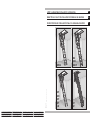 1
1
-
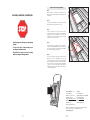 2
2
-
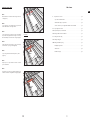 3
3
-
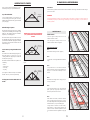 4
4
-
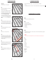 5
5
-
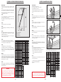 6
6
-
 7
7
-
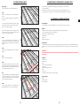 8
8
-
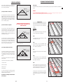 9
9
-
 10
10
-
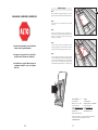 11
11
-
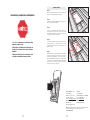 12
12
-
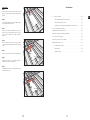 13
13
-
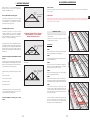 14
14
-
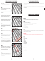 15
15
-
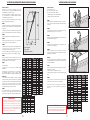 16
16


Fakro 869716 Guía de instalación
- Tipo
- Guía de instalación
en otros idiomas
- français: Fakro 869716 Guide d'installation
- English: Fakro 869716 Installation guide
Artículos relacionados


Otros documentos
-
Simpson Strong-Tie IUS2.56/11.88 Guía de instalación
-
Werner AH2210 Guía de instalación
-
Keller AA1510CA Instrucciones de operación
-
 Louisville WL2211L Guía de instalación
-
Louisville Ladder AA2210 Instrucciones de operación
-
 Louisville AEE2210 Guía de instalación
-
 Air Vent WH362BDX Instrucciones de operación
-
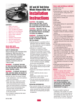 Air Vent 54506 Guía de instalación
-
Worx WX176L.1 Guía del usuario
-


