Crafstman 01527-0 Manual de usuario
- Categoría
- Generadores de poder
- Tipo
- Manual de usuario
Este manual también es adecuado para

Generator
Customer Helpline
1-800-222-3136
120/240 Volt
Electric Start
7500 Watt
AC GENERATOR
Sears, Roebuck and Co., Hoffman Estates, IL 60179
Owner’s Manual
Model No. 580.329180
CAUTION:
Before using this product, read this
manual and follow all its Safety Rules
and Operating Instructions.
Part No. 186936 Draft 0 (8/16/2000) Printed in the U.S.A.
Visit our Craftsman website: www.sears.com/craftsman
• Safety
• Assembly
• Operation
• Maintenance
• Parts
• Espanõl
HOURS: Mon. - Fri. 8 a.m. to 5 p.m. (CT)

2
TABLE OF CONTENTS
Warranty . . . . . . . . . . . . . . . . . . . . . . . . . . . . . . . . . .2
Safety Rules . . . . . . . . . . . . . . . . . . . . . . . . . . . . . . .3
Assembly . . . . . . . . . . . . . . . . . . . . . . . . . . . . . . .4–5
Operation . . . . . . . . . . . . . . . . . . . . . . . . . . . . . .6–12
Product Specifications . . . . . . . . . . . . . . . . . . . . . . .13
Maintenance . . . . . . . . . . . . . . . . . . . . . . . . . . .13–16
Storage . . . . . . . . . . . . . . . . . . . . . . . . . . . . . . . . . .17
Troubleshooting . . . . . . . . . . . . . . . . . . . . . . . . . . . .18
Schematic/Wiring Diagram . . . . . . . . . . . . . . . . .20–21
Replacement Parts . . . . . . . . . . . . . . . . . . . . . .22–29
Emissions Warranty . . . . . . . . . . . . . . . . . . . . . . . . .30
Español . . . . . . . . . . . . . . . . . . . . . . . . . . . . . . .31-51
How to Order Parts . . . . . . . . . . . . . . . . . . .Back Page
LIMITED WARRANTY FOR DELUXE PORTABLE GENERATORS
SEARS warrants to the original purchaser that the alternator and engine for its portable generator will be free
from defects in materials or workmanship for the items and period set forth below from the date of original
purchase. This warranty is not transferable and applies only to portable generators driven by the GN-Series
Sears warranted engine.
CONSUMER* COMMERCIAL*
Alternator 2 years (2nd year parts only) 1 year
Engine 2 years (2nd year parts only) 1 year
* NOTE: For the purpose of this warranty “Consumer Use” means personal residential household and
emergency use by original purchaser, not to be used as a primary source of power. “Commercial Use” means all
other uses, including rental, construction, commercial, and income producing purposes. Once a generator has
experienced commercial use, it shall thereafter be considered a commercial use generator for the purpose of
this warranty.
During said warranty period, SEARS will, at its option, repair or replace any part which, upon examination by
SEARS, is found to be defective under normal use and service**. Starting batteries are not warranted by
SEARS. All transportation costs under warranty, including return to the factory if necessary, are to be borne by
the purchaser and prepaid by him. This warranty does not cover normal maintenance and service and does not
apply to a generator set, alternator or engine, or parts which have been subjected to improper or unauthorized
installation or alteration, misuse, negligence, accident, overloading, overspeeding, improper maintenance, repair
or storage so as, in SEARS’s judgment, to adversely affect its performance and reliability.
** NORMAL WEAR: As with all mechanical devices, engines need periodic parts service and replacement to
perform well. This warranty will not cover repair when normal use has exhausted the life of a part or engine.
THERE IS NO OTHER EXPRESS WARRANTY. SEARS HEREBY DISCLAIMS ANY AND ALL
IMPLIED WARRANTIES, INCLUDING BUT NOT LIMITED TO THOSE OF MERCHANTABILITY AND
FITNESS FOR A PARTICULAR PURPOSE TO THE EXTENT PERMITTED BY LAW. THE DURATION
OF ANY IMPLIED WARRANTIES WHICH CANNOT BE DISCLAIMED IS LIMITED TO THE TIME
PERIOD AS SPECIFIED IN THE EXPRESS WARRANTY. LIABILITY FOR CONSEQUENTIAL,
INCIDENTAL, OR SPECIAL DAMAGES UNDER ANY AND ALL WARRANTIES IS EXCLUDED.
Some states do not allow limitations on how long an implied warranty lasts, or the exclusion or limitation of
incidental or consequential damages, so the above limitations or exclusions may not apply to you. This warranty
gives you specific legal rights and you may also have other rights, which vary from state to state.
For service, see your nearest SEARS authorized warranty service facility. Warranty service can be performed
only by a SEARS authorized service facility. This warranty will not apply to service at any other facility. At the
time of requesting warranty service, evidence of original purchase date must be presented.
Sears, Roebuck and Co., D/817WA, Hoffman Estates, IL 60179
WARRANTY

3
CAUTION! Before using this product, read this
manual and follow all Safety Rules and
Operating Instructions.
DANGER! This generator is designed for
outdoor use only. Do Not use this generator
inside any building or enclosure including the
generator compartment of a recreational vehicle
(RV). Fire or an explosion may result. No user
performed modifications, including venting of
exhaust and/or cooling ventilation, will eliminate
the danger. Also, allow at least two feet of
clearance on all sides of the generator while
operating the unit.
CAUTION! Always disconnect spark plug wire
and place the wire where it cannot contact the
spark plug to prevent accidental starting when
setting up, transporting, adjusting or making
repairs to your generator.
• The generator produces dangerously high voltage
that can cause extremely hazardous electrical
shock. Avoid contact with bare wires, terminals,
etc. Never permit any unqualified person to
operate or service the generator.
• Never handle any kind of electrical cord or device
while standing in water, while barefoot or while
hands or feet are wet. Dangerous electrical shock
will result.
• The National Electric Code requires the frame and
external electrically conductive parts of generator
be properly connected to an approved earth
ground. Local electrical codes may also require
proper grounding of the generator. Consult with a
local electrician for grounding requirements in your
area.
• Use a ground fault circuit interrupter in any damp
or highly conductive area (such as metal decking or
steel work).
• Do Not use worn, bare, frayed or otherwise
damaged electrical cord sets with the generator.
• Operate generator only on level surfaces and
where it will not be exposed to excessive moisture,
dirt, dust or corrosive vapors.
• Gasoline is highly FLAMMABLE and its vapors are
EXPLOSIVE. Do Not permit smoking, open flames,
sparks or heat in the vicinity while handling
gasoline. Avoid spilling gasoline on a hot engine.
Comply with all laws regulating storage and
handling of gasoline.
• Never add fuel while unit is running.
• Do Not overfill the fuel tank. Always allow room for
fuel expansion. If tank is overfilled, fuel can
overflow onto a hot engine and cause FIRE or an
EXPLOSION.
• Never store generator with fuel in tank where
gasoline vapors might reach an open flame or
spark or pilot light (as on a furnace, water heater or
clothes dryer). FIRE or EXPLOSION may result.
• Generator exhaust gases contain DEADLY carbon
monoxide gas. This dangerous gas, if breathed in
sufficient concentrations, can cause
unconsciousness or even death. Operate this
equipment only in the open air where adequate
ventilation is available.
• Allow at least 2 feet of clearance on all sides of
generator or you could damage the unit. Never
operate the unit inside any room or enclosure
where the free flow of cooling air into and out of the
unit might be obstructed. Review “Cold Weather
Operation” on page 10.
• Never start or stop the unit with electrical loads
connected to receptacles AND with connected
devices turned ON. Start the engine and let it
stabilize before connecting electrical loads.
Disconnect all electrical loads before shutting down
the generator.
• Do Not insert objects through units cooling slots.
• Never operate generator:
in rain; in any enclosed compartment; when
connected electrical devices overheat; if electrical
output is lost; if engine or generator sparks; if
flames or smoke are observed while unit is running;
if unit vibrates excessively.
NOTE: Your generator is equipped with a spark
arrester muffler. The spark arrester must be
maintained in effective working order by the owner/
operator. In the State of California, a spark arrester is
required by law (Section 4442 of the California Public
Resources Code). Other states may have similar laws.
Federal laws apply on federal lands.
SAFETY RULES
The engine exhaust from this product contains
chemicals known to the State of California
to cause cancer, birth defects,
or other reproductive harm.
WARNING:
LOOK FOR THIS SYMBOL TO POINT OUT IMPORTANT SAFETY PRECAUTIONS. IT MEANS
“ATTENTION!!! BECOME ALERT!!! YOUR SAFETY IS INVOLVED.”

Your generator requires some assembly and is ready
for use after it has been properly serviced with the
recommended oil and fuel.
If you have any problems with the assembly of
your generator, please call the generator helpline
at 1-800-222-3136.
IMPORTANT: Any attempt to run the engine before it
has been serviced with the recommended oil will result
in an engine failure.
TO REMOVE GENERATOR FROM
CARTON
• Slice two corners at end of carton from top to
bottom so the panel can be folded down flat.
• Remove all packing material, carton fillers, etc.
• Remove the generator and tranfer switch container
from the shipping carton.
CARTON CONTENTS
• Generator
• Wheel kit
• Locking plug
• Engine oil
• Transfer switch components
• Battery tray components
• Battery charge cable
• Manual
Check all contents. If any parts are missing or
damaged, call the generator helpline at
1-800-222-3136.
INSTALLING TRAY AND BATTERY
NOTE: The generator can be started manually. If you
choose not to use the electric start feature of this
generator, you do not need to install the battery.
You must purchase and install a 12 Volt DC battery
(Sears p/n 28-27145). The battery should be serviced
with electrolyte fluid and fully charged prior to
installation.
• Find the battery tray and fasteners shipped loose in
the carton. Included are: one hold-down bracket,
two 7" J bolts, two lock washers, two flat washers
and two hex nuts.
• Remove the 4 battery tray screws from cradle.
• Position the battery tray and install with supplied
hardware.
• Set battery onto tray. Position hold-down bracket.
• Retain battery to tray with two J bolts, two lock
washers, two flat washers and two hex nuts, as
shown.
• Connect the red battery cable from the engine
starter switch to the positive (+) terminal on the
battery.
• Connect the black battery cable to the negative (–)
terminal on the battery.
• Connect the other end of the black cable to the
engine as shown.
WARNING!
Do Not connect the black battery
cable to any other location.
• Double check all connections to ensure they are in
the correct locations and secure.
ASSEMBLY
4
RED (+)
wire from
battery
BLACK (–) wire
from battery

5
ASSEMBLING THE WHEEL KIT
The wheel kit is designed to greatly improve the
portability of your generator.
NOTE: Wheel kit is not intended for over-the-road use.
You will need a socket wrench with 1/2" or 13mm
sockets and a needle-nose plier to install this kit.
Refer to illustration shown below and install the wheel
kit as follows:
• Place the generator on a hard flat surface.
• Stand at the engine end of the generator and
gently tilt the generator forward, high enough to
place wooden blocks beneath the cradle. This will
allow you to add the wheels.
• Slide the axle through the holes in the brackets
provided on the generator cradle.
• Slide one wheel and flat washer on each end of the
axle. Make sure the air inflation valve is outward.
Insert both retaining pins using the needle-nose
plier. Remove the wooden blocks.
• Attach the vibration mounts to the support leg with
30mm capscrews, washers and lock nuts.
• With the wheels on, you can now lift up the handle
end and attach the support leg with 20mm cap
screws and lock nuts.
• Check each fastener to ensure it is secure.
Retaining Pin
Flatwasher
Wheels
Axle
20mm
Capscrew
Locknut
30mm Capscrew
Flatwasher
Vibration Mount
Support Leg
Locknut

6
KNOW YOUR GENERATOR
Read the owner’s manual and safety rules before operating your generator.
Compare the illustrations with your generator to familiarize yourself with the locations of various controls and
adjustments. Save this manual for future reference.
12 Volt DC, 10 Amp Receptacle —This receptacle
allows you to recharge a 12 Volt DC storage battery
with provided battery charge cables.
120 Volt AC, 20 Amp, Duplex Receptacle —
Supplies electrical power for the operation of 120 Volt
AC, 20 Amp, single phase, 60 Hz electrical lighting,
appliance, tool and motor loads.
120 Volt AC, 30 Amp Locking Receptacle —
Supplies electrical power for the operation of 120 Volt
AC, 30 Amp, single phase, 60 Hz electrical lighting,
appliance, tool and motor loads.
120/240 Volt AC, 30 Amp Locking Receptacle —
Supplies electrical power for the operation of 120
and/or 240 Volt AC, 30 Amp, single phase, 60 Hz
electrical lighting, appliance, tool and motor loads.
120/240 Volt AC, 50 Amp Receptacle — Supplies
electrical power for the operation of 120/240 Volt AC,
50 Amp, single phase, 60 Hz, welder or motor loads.
Air Cleaner — Filters intake air as it is drawn into the
engine.
Choke Lever — Used when starting a cold engine.
Circuit Breakers (AC) — Each receptacle is provided
with a push-to-reset circuit breaker to protect the
generator against electrical overload.
Fuel Tank — Tank holds 8 U.S. gallons of fuel.
Grounding Lug — Ground the generator to an
approved earth ground here. See page 8 for details.
Idle Control Switch — The idle control runs the
engine at normal (high) speeds when there is an
electrical load present and runs the engine at idle
(low) speeds the rest of the time.
Run/Stop Switch — Must be in “Run” position to start
engine. Set to “Stop” to stop a running engine.
Spark Arrester Muffler — Muffler lowers engine
noise and is equipped with a spark arrester screen.
OPERATION
Fuel Tank
Air Cleaner
Run/Stop
Switch
Choke Lever
12 Volt DC,
10 Amp Receptacle
Circuit Breakers (AC)
Idle Control
Switch
120/240 Volt AC, 30 Amp
Locking Receptacle
120 Volt AC, 30 Amp
Locking Receptacle
120/240 Volt AC,
50 Amp Receptacle
Grounding Lug
120 Volt AC, 20 Amp
Duplex Receptacle
Spark Arrester Muffler

CONNECTOR PLUGS
120 Volt AC, 20 Amp, Duplex Receptacle
This is a 120 Volt outlet protected against overload by
a 20 Amp push-to-reset circuit breaker. Use each
socket to power 120 Volt AC, single phase, 60 Hz
electrical loads requiring up to a combined 2,400 watts
(2.4 kW) or 20 Amps of current. Use only high quality,
well-insulated, 3-wire grounded cord sets rated for
125 Volts at 20 Amps (or greater).
Keep extension cords as short as possible, preferably
less than 15 feet long, to prevent voltage drop and
possible overheating of wires.
120 Volt AC, 30 Amp Receptacle
Use a NEMA L5-30 plug with this receptacle. Connect
a 3-wire cord set rated for 125 Volts AC at 30 Amps
(or greater) to the plug.
Use this receptacle to operate 120 Volt AC, 60 Hz,
single phase loads requiring up to 3,600 watts
(3.6 kW) of power at 30 Amps. The outlet is protected
by a 30 Amp push-to-reset circuit breaker.
120/240 Volt AC, 30 Amp Receptacle
Use a NEMA L14-30 plug with this receptacle.
Connect a suitable 4-wire grounded cord set to the
plug and to the desired load. The cord set should be
rated for 250 Volts AC at 30 Amps (or greater).
Use this receptacle to operate 120 Volt AC, 60 Hz,
single phase loads requiring up to 3,600 watts
(3.6 kW) of power at 30 Amps or 240 Volt AC, 60 Hz,
single phase loads requiring up to 7,200 watts
(7.2 kW) of power at 30 Amps. The outlet is protected
by a 30 Amp push–to–reset circuit breaker.
12 Volt DC, 10 Amp Receptacle
This receptacle allows you to recharge a 12 Volt
automotive or utility style storage battery with the
battery charge cables provided. This receptacle can
not recharge 6 Volt batteries and can not be used to
crank an engine having a discharged battery. See the
section “Charging a Battery” (page 11) before
attempting to recharge a battery.
7

120/240 Volt AC, 50 Amp Receptacle
Use a NEMA 14–50 plug with this receptacle. Connect
a 4-wire cord set rated for 250 Volts AC at 50 Amps to
the plug.
Use this receptacle to operate 120/240 Volt AC, 60 Hz
electrical loads requiring up to 7,500 watts (7.5 kW) of
power.
CAUTION! Although this outlet states it has a
240 Volt 50 Amp rating (up to 12,500 watts), the
generator is only rated for 7,500 watts.
Powering loads that exceed the wattage/
amperage capacity of the generator can
damage it and cause serious injuries.
HOW TO USE YOUR GENERATOR
If you have any problems operating your generator,
please call the generator helpline at 1-800-222-3136.
Grounding The Generator
The National Electrical Code requires that the
frame and external electrically conductive parts of
this generator be properly connected to an
approved earth ground. Local electrical codes may
also require proper grounding of the unit. For that
purpose, a grounding wing nut is provided on the
generator.
Generally, connecting a No. 12 AWG (American Wire
Gauge) stranded copper wire to the grounding wing
nut and to an earth-driven copper or brass grounding
rod (electrode) provides adequate protection against
electrical shock. However, local codes may vary
widely. Consult with a local electrician for
grounding requirements in your area.
Proper grounding of the generator will help
prevent electrical shock in the event of a ground
fault condition in the generator or in connected
electrical devices. Proper grounding also helps
dissipate static electricity, which often builds up in
ungrounded devices.
Connecting Electrical Loads
• Do Not connect 240 Volt loads to 120 Volt
receptacles.
• Do Not connect 3-phase loads to the generator.
• Do Not connect 50 Hz loads to the generator.
• Let engine stabilize and warm up for a few minutes
after starting.
• Plug in and turn on the desired 120 or 240 Volt AC,
single phase, 60 Hz electrical loads.
• Add up the rated watts (or amps) of all loads to be
connected at one time. This total should not be
greater than (a) the rated wattage/amperage
capacity of the generator or (b) circuit breaker
rating of the receptacle supplying the power. See
“Don’t Overload the Generator” on page 12.
8
Grounding Wing Nut

BEFORE STARTING THE
GENERATOR
To operate the generator you will need to first add
engine oil and gasoline, as follows:
Add Engine Oil
NOTE: When adding oil to the engine crankcase in
the future, use only high quality detergent oil rated
with API service classification SF or SG SAE 30
weight. Use no special additives.
Select the oil’s viscosity grade according to your
expected operating temperature. Do Not use
SAE 10W-40.
• Above 40°F, use SAE 10W–30 or SAE 30.
• Below 40°F, use synthetic 5W–20 or 5W–30.
Although multi-viscosity oils (5W30, 10W30, etc.)
improve starting in cold weather, these multi-viscosity
oils will result in increased oil consumption when used
above 32°F. Check your engine oil level more
frequently to avoid possible damage from running low
on oil.
• Place generator on a level surface.
• Clean area around yellow oil fill cap. Remove the
oil fill cap.
• Slowly fill engine with oil through the oil fill opening
until the oil level is to the point of overflowing.
• Install yellow oil fill cap and finger tighten securely.
• Check engine oil level before starting each time
thereafter. If the oil level is below the point of
overflowing, fill to the proper level.
Add Gasoline
WARNING! Never fill fuel tank indoors. Never
fill fuel tank when engine is running or hot.
Do Not light a cigarette or smoke when filling
the fuel tank.
CAUTION! Do Not overfill the fuel tank.
Always leave room for expansion.
• Use regular UNLEADED gasoline with the
generator engine. Do Not use premium gasoline.
Do Not mix oil with gasoline.
• Clean area around fuel fill cap, remove cap.
• Slowly add unleaded regular gasoline to fuel tank.
Be careful not to overfill. Allow about 1/2" of tank
space for fuel expansion, as shown here.
• Install fuel cap and wipe up any spilled gasoline.
IMPORTANT: It is important to prevent gum deposits
from forming in fuel system parts such as the
carburetor, fuel hose or tank during storage. Alcohol-
blended fuels (called gasohol, ethanol or methanol)
can attract moisture, which leads to separation and
formation of acids during storage. Acidic gas can
damage the fuel system of an engine while in storage.
To avoid engine problems, the fuel system should be
emptied before storage of 30 days or longer. See
“Storage” on page 17. Never use engine or carburetor
cleaner products in the fuel tank as permanent
damage may occur.
TO START THE ENGINE
WARNING! Never start or stop engine with
electrical devices plugged into the receptacles
AND devices turned ON.
• Unplug all electrical loads from units receptacles
before starting the engine.
• Make sure the unit is in a level position.
• Open the fuel shut–off valve.
• Locate the Idle Control ON/OFF switch on the
control panel and set it to the “OFF” position.
9
10W–30, SAE 30
Synthetic 5W–20, 5W–30
OFF
position
Fuel Valve shown in
Open Position

• Place the Run/Stop Switch in the “Run” position.
• Move engine Choke lever to “Full” choke position.
• For electric starting: Press start switch on
generator cradle. To prolong the life of the starter
components, press the starter button for no more
than 15 seconds, and pause for 30 seconds.
• For manual starting: Grasp the recoil handle and
pull slowly until slight resistanceis felt. Then pull
rapidly one time only to start engine.
• If engine starts, skip the next step. If engine
fails to start, proceed to the next step.
• Move choke lever to “Half” choke position, and pull
recoil twice.
• If engine fails to start, repeat all steps in “To
Start The Engine” beginning on page 9.
• Move choke lever to “Run” position. If engine
falters, move choke lever to “Half” choke position
until the engine runs smoothly and then to “Run”
position.
NOTE: If engine fails to start after 3 pulls (or
15 seconds cranking), check for proper oil level in
crankcase. This unit is equipped with a Low Oil
Shutdown System (see page 11).
STOPPING THE ENGINE
• Unplug all electrical loads from generator panel
receptacles. Never start or stop engine with
electrical devices plugged in and turned on.
• Turn “Off” the Idle Control switch (if On).
• Let engine run at no-load for several minutes to
stabilize the internal temperatures of engine and
generator.
• Move Run/Stop switch to “Stop” position.
• Close fuel valve.
IMPORTANT: Do Not overload the generator. Also,
Do Not overload individual panel receptacles. These
outlets are protected against overload with push-to-
reset-type circuit breakers. If amperage rating of any
circuit breaker is exceeded, that breaker opens and
electrical output to that receptacle is lost. Read “Don’t
Overload the Generator” on page 12 carefully.
AUTOMATIC IDLE CONTROL
This feature is designed to greatly improve fuel
economy. When this switch is turned “On,” the engine
will only run at its normal fast governed engine speed
when an electrical load is connected. When the load is
removed, the engine will run at a reduced speed. With
the switch “Off,” the engine runs at the normal fast
engine speed all the time. Always have the switch
OFF when starting and stopping the engine.
COLD WEATHER OPERATION
Under certain weather conditions (temperatures below
40°F [4°C] and a high dew point), your generator may
experience icing of the carburetor and/or the
crankcase breather system. In an emergency, use the
original shipping box as a temporary shelter:
• Cut off all flaps and one of the long sides of the
box to expose exhaust side of unit. Cut appropriate
slots to access receptacles of unit.
• Start unit, then place box over it. Ensure a
minimum of two feet clearance between open side
of box and nearest object.
IMPORTANT: Remove shelter when temperature is
above 40°F [4°C].
For a more permanent shelter, build a structure that
will enclose three sides and the top of the generator.
Make sure entire muffler-side of generator is exposed,
with two feet clearance between open side of box and
nearest object. Face exposed end away from wind
and elements, as shown.
10
“Full” Choke
Position
Wind

11
LOW OIL PRESSURE SHUTDOWN
SYSTEM
The engine is equipped with a low oil pressure sensor
that shuts down the engine automatically when the oil
pressure drops below 6 psi. If the engine shuts down
by itself and the fuel tank has enough gasoline, check
engine oil level.
Initial Start–up
A delay built into the low oil shutdown system allows
oil pressure to build during starting. The delay allows
the engine to run for about 10 seconds before sensing
oil pressure.
Sensing Low Pressure
If the system senses low oil pressure during operation,
the engine shuts down.
Restarting
If you try to restart the engine within 10 seconds after
it shuts down, the engine may NOT start. The system
needs 5 to 10 seconds to reset.
If you do restart the engine after such a shutdown and
have not corrected the low oil pressure, the engine
runs for about 10 seconds as described above and
then stops.
CHARGING A BATTERY
DANGER! Storage batteries give off explosive
hydrogen gas while recharging. An explosive
mixture will remain around the battery for a long
time after it has been charged. The slightest
spark can ignite the hydrogen and cause an
explosion. Such an explosion can shatter the
battery and cause blindness or other serious
injury.
DANGER! Do Not permit smoking, open
flame, sparks or any other source of heat
around a battery. Wear protective goggles,
rubber apron and rubber gloves when working
around a battery. Battery electrolyte fluid is an
extremely caustic sulfuric acid solution that can
cause severe burns. If spill occurs, flush area
with clear water immediately.
Your generator has the capability of recharging a
discharged 12 Volt automotive or utility style storage
battery. Do Not use the unit to charge any 6 Volt
batteries. Do Not use the unit to crank an engine
having a discharged battery.
To recharge 12 Volt batteries, proceed as follows:
• Check fluid level in all battery cells. If necessary,
add ONLY distilled water to cover separators in
battery cells. Do Not use tap water.
• If the battery is equipped with vent caps, make
sure they are installed and are tight.
• If necessary, clean battery terminals.
• Connect battery charge cable connector plug to
panel receptacle identified by the words
“12 Volt DC”.
• Connect battery charge cable clamp with red
handle to the positive (+) battery terminal.
• Connect battery charge cable clamp with black
handle to the negative (–) battery terminal.
• Start engine. Let the engine run while battery
recharges.
• When battery has charged, shut down engine.
NOTE: Use an automotive hydrometer to test battery
state of charge and condition. Follow the hydrometer
manufacturer’s instructions carefully. Generally, a
battery is considered to be at 100% state of charge
when specific gravity of its fluid (as measured by
hydrometer) is 1.260 or higher.

DON’T OVERLOAD THE
GENERATOR
Overloading a generator in excess of its rated wattage
capacity can result in damage to the generator and to
connected electrical devices. Observe the following to
prevent overloading the unit:
• Add up the total wattage of all electrical devices to
be connected at one time. This total should NOT
be greater than the generator’s wattage capacity.
• The rated wattage of lights can be taken from light
bulbs. The rated wattage of tools, appliances and
motors can usually be found on a data plate or
decal affixed to the device.
• If the appliance, tool or motor does not give
wattage, multiply volts times ampere rating to
determine watts (volts x amps = watts).
• Some electric motors, such as induction types,
require about three times more watts of power for
starting than for running. This surge of power lasts
only a few seconds when starting such motors.
Make sure you allow for this high starting wattage
when selecting electrical devices to connect to your
generator:
1. Figure the watts needed to start the largest
motor.
2. Add to that figure the running watts of all other
connected loads.
The Wattage Reference Guide below is provided to
assist you in determining how many items your
generator can operate at one time.
NOTE: All figures are approximate. See data plate on
appliance for wattage requirements.
Recreational/Home Uses
Tool/Appliance . . . . . . . . . . . . . . . . . . . . . . . . Watts
AM/FM clock radio. . . . . . . . . . . . . . . . . . . . . . . . . 50
Light bulb. . . . . . . . . . . . . . . . . . . . . . . . . . . . . . . 100
Fan . . . . . . . . . . . . . . . . . . . . . . . . . . . . . . . . . . . 200
20" color TV. . . . . . . . . . . . . . . . . . . . . . . . . . . . . 400
*Deep freezer . . . . . . . . . . . . . . . . . . . . . . . . . . . 500
Personal computer and 15" monitor . . . . . . . . . . . 800
*1/3 hp furnace fan blower. . . . . . . . . . . . . . . . . . 800
Microwave oven. . . . . . . . . . . . . . . . . . . . . . . . . . 800
*18 cu ft refrigerator. . . . . . . . . . . . . . . . . . . . . . . 800
Sump pump. . . . . . . . . . . . . . . . . . . . . . . . . . . . 1000
Electric skillet. . . . . . . . . . . . . . . . . . . . . . . . . . . 1250
*½ hp water well pump. . . . . . . . . . . . . . . . . . . . 1400
*12,000 Btu window air conditioner . . . . . . . . . . 1400
Space heater. . . . . . . . . . . . . . . . . . . . . . . . . . . 1800
Electric water heater . . . . . . . . . . . . . . . . . . . . . 4000
Professional/Contractor Uses
Tool/Appliance . . . . . . . . . . . . . . . . . . . . . . . . Watts
*1/3 hp airless sprayer. . . . . . . . . . . . . . . . . . . . . 600
3/8" hammer drill . . . . . . . . . . . . . . . . . . . . . . . . . 600
Variable speed Sawzall®. . . . . . . . . . . . . . . . . . . 960
½" power drill. . . . . . . . . . . . . . . . . . . . . . . . . . . 1000
Quartz-halogen work light . . . . . . . . . . . . . . . . . 1000
Belt sander . . . . . . . . . . . . . . . . . . . . . . . . . . . . 1200
7 ¼" circular saw . . . . . . . . . . . . . . . . . . . . . . . . 1500
7 ¼" worm drive saw . . . . . . . . . . . . . . . . . . . . . 1600
*1½ hp air compressor. . . . . . . . . . . . . . . . . . . . 1800
*10" power miter saw. . . . . . . . . . . . . . . . . . . . . 1800
6" bench grinder . . . . . . . . . . . . . . . . . . . . . . . . 1800
*6" table planer . . . . . . . . . . . . . . . . . . . . . . . . . 1800
*10" table/radial arm saw . . . . . . . . . . . . . . . . . . 2000
Wire feed welder . . . . . . . . . . . . . . . . . . . . . . . . 2400
* allow 3 times listed watts for starting this device
WATTAGE REFENCE GUIDE
12

PRODUCT SPECIFICATIONS
Generator Specifications
Rated Maximum Power . . . . . . . 7,500 Watts (7.5 kW)
Surge Power . . . . . . . . . . . . . . . 9,375 Watts (9.3 kW)
Rated AC Voltage . . . . . . . . . . . 120/240 Volts
Rated Maximum AC Load Current
at 240 Volts . . . . . . . . . . . . . . 31.2 Amperes
at 120 Volts . . . . . . . . . . . . . . 62.5 Amperes
Rated Frequency . . . . . . . . . . . . 60 Hz at 3600 rpm
Phase . . . . . . . . . . . . . . . . . . . . Single Phase
Rated DC Voltage . . . . . . . . . . . 12 Volts
Rated Maximum DC Load Current
at 12 Volts . . . . . . . . . . . . . . . 10.0 Amperes
Engine Specifications
Rated Horsepower . . . . . . . . . . . 15 at 3600 rpm
Displacement . . . . . . . . . . . . . . . 410 cc
Spark Plug
Type:. . . . . . . . . . . . . . . . . . . . Champion RC12YC or
Equivalent
Set Gap To:. . . . . . . . . . . . . . . 0.030 inch (0.76mm)
Gasoline Capacity . . . . . . . . . . . 8 U.S. gallons
Oil Type:
Above 32° F . . . . . . . . . . . . . . SAE 30 or 10W-30
Below 32° F. . . . . . . . . . . . . . . Synthetic 5W-20 or
5W-30
GENERAL RECOMMENDATIONS
The generator warranty does not cover items that
have been subjected to operator abuse or negligence.
To receive full value from the warranty, the operator
must maintain the generator as instructed in this
manual.
Some adjustments will need to be made periodically to
properly maintain the generator.
All adjustments in the Service and Adjustments
section of this manual should be made at least once
each season. Follow the requirements in the
“Maintenance Schedule” chart above.
NOTE: Once a year you should clean or replace the
spark plug and replace the air filter. A new spark plug
and clean air filter assure proper fuel-air mixture and
help your engine run better and last longer.
Generator Maintenance
Generator maintenance consists of keeping the unit
clean and dry. Operate and store the unit in a clean
dry environment where it will not be exposed to
excessive dust, dirt, moisture or any corrosive vapors.
Cooling air slots in the generator must not become
clogged with snow, leaves, or any other foreign
material.
Check the cleanliness of the generator frequently and
clean when dust, dirt, oil, moisture or other foreign
substances are visible on its exterior surface.
CAUTION! Never insert any object or tool
through the air cooling slots, even if the engine
is not running.
13
MAINTENANCE
‡ Change oil after first 8 hours of operation then after every 50 hours or every season.
* Change oil and oil filter every 25 hours when operating under heavy load or in high temperatures.
** Clean more often under dirty or dusty conditions. Replace air cleaner parts if very dirty.
*** Retorque head bolts only after the first 50 hours. Head bolts will not need further retorquing.
MAINTENANCE SCHEDULE
Follow the hourly or calendar intervals, whichever occurs first. More frequent service is required when
operating in adverse conditions noted below.
Maintenance Operation
Every 8 Hours
or Daily
25 Hours or
Every Season
50 Hours or
Every Season
100 Hours or
Every Season
Check Oil Level
X
Service Air Pre-Cleaner
X**
Change Oil And Oil Filter‡
X*
Clean Spark Arrestor Screen
X
Adjust Valve Clearance
X
Retorque Head Bolts
X***
Service Air Cleaner
X**
Replace Spark Plugs
X

14
NOTE: Do Not use a garden hose to clean generator.
Water can enter the engine fuel system and cause
problems. In addition, if water enters the generator
through cooling air slots, some water will be retained
in voids and cracks of the rotor and stator winding
insulation. Water and dirt buildup on the generator
internal windings will eventually decrease the
insulation resistance of these windings.
To Clean the Generator:
• Use a damp cloth to wipe exterior surfaces clean.
• A soft, bristle brush may be used to loosen caked
on dirt, oil, etc.
• A vacuum cleaner may be used to pick up loose
dirt and debris.
• Low pressure air (not to exceed 25 psi) may be
used to blow away dirt. Inspect cooling air slots
and openings on the generator. These openings
must be kept clean and unobstructed.
Engine Maintenance
DANGER! When working on the generator,
always disconnect negative cable from battery.
Also disconnect spark plug wires from spark
plug and keep wire away from spark plug.
Checking Oil Level
See “BEFORE STARTING THE GENERATOR” on
page 9 for information on checking the oil level. The
oil level should be checked before each use, or at
least every eight hours of operation. Keep the oil
level maintained.
Changing the Oil and Oil Filter
Change the oil and filter after the first eight hours of
operation. Change the oil every 50 hours
thereafter. If you are running this unit under dirty or
dusty conditions, or in extremely hot weather, change
the oil more often.
Use the following instructions to change the oil
while the engine is still warm:
• Clean area around oil drain plug and oil fill cap.
• Remove oil fill cap and oil drain plug. Drain oil
completely into a suitable container.
• When oil has completely drained, install oil drain
plug and tighten securely.
• Place a suitable container beneath the oil filter and
turn filter counterclockwise to remove. Discard
according to local regulations.
• Coat gasket of new filter with fresh clean engine
oil. Turn filter clockwise until gasket contacts tightly
with filter adapter. Then tighten 3/4 turn more.
• Fill engine with recommended oil. (See “BEFORE
STARTING THE Generator” on page 9 for oil
recommendations).
• Install the oil fill cap and tighten securely.
• Wipe up any spilled oil.
Replacing the Spark Plug
Use the recommended spark plug gapped to 0.76 mm
(0.030 in.). Replace the plug every 100 hours of
operation or once each year, whichever comes first.
This will help your engine start easier and run better.
1. Stop the engine and pull the spark plug wire off of
the spark plug.
2. Clean the area around the spark plug and remove
it from the cylinder head.
3. Set the spark plug’s gap to 0.76 mm (0.030 in.).
Install the correctly gapped spark plug into the
cylinder head.
Retorque Head Bolts
After the first 50 hours of operation, you must retorque
the head bolts to 6.9 kg.-m. (44 ft.-lbs.).
IMPORTANT: If you feel uncomfortable about doing
this procedure or you don’t have the proper tools,
please take your generator in to the nearest Sears
service center to have the head bolts re-torqued. This
is a very important step to insure the longest life for
your engine.
NOTE: Only perform this adjustment after the first
50 hours of operation. The head bolts will need no
further adjustment.
• Torque sequence is as follows: A, B, C, D,
(alternating pattern).
D
A
C
B

15
Service Air Cleaner
Your engine will not run properly and may be
damaged if you run it using a dirty air cleaner. Clean
or replace the air cleaner paper filter once every
50 hours of operation or once a year, whichever
comes first. Clean or replace more often if operating
under dusty conditions. Clean foam precleaner every
25 hours of operation or sooner under dusty
conditions.
To clean or replace foam precleaner:
• Remove air cleaner cover, then foam pre-filter.
• Wash precleaner in soapy water. Squeeze pre-filter
dry in clean cloth (Do Not Twist).
• Clean air cleaner cover before installing it.
To clean or replace paper air filter:
• Remove air cleaner cover; then remove foam pre-
filter (service if necessary) and remove paper filter.
• Clean paper filter by tapping it gently on a solid
surface. If the filter is too dirty, replace it with a new
one. Dispose of the old filter properly.
• Clean air cleaner cover then insert precleaner into
cover. Next insert new paper filter into cover to
hold precleaner in place and assemble all of them
to the base of the air cleaner.
NOTE: If you need to order a new air filter, please call
1-800-366-PART.
Clean Spark Plugs
The engine exhaust muffler has a spark arrester
screen. Inspect and clean the screen every
100 hours of operation or once each year, whichever
comes first.
NOTE: If you use your generator on any forest-
covered, brush-covered or grass-covered unimproved
land, it must equipped with a spark arrester. The spark
arrester must be maintained in good condition by the
owner/operator.
Clean and inspect the spark arrester as follows:
• To remove the muffler guard from the muffler,
remove the four screws that connect the guard to
the muffler bracket.
• Remove four screws that attach the spark arrester
screen.
• Inspect screen and replace if torn, perforated or
otherwise damaged. Do Not use a defective
screen. If screen is not damaged, clean it with
commercial solvent.
• Reattach the screen and the muffler guard.

16
Adjusting Valve Clearance
After the first 50 hours of operation, you should
adjust the valve clearance in the engine.
IMPORTANT: If you feel uncomfortable about doing
this procedure or you don’t have the proper tools,
please take your generator in to the nearest Sears
service center to have the valve clearance adjusted.
This is a very important step to insure longest life for
your engine.
To adjust valve clearance:
• Make sure the engine is at room temperature.
• Make sure that the spark plug wire is removed from
the spark plug and out of the way.
• Remove the breather tube from the valve cover.
• Remove the four screws attaching the valve cover
with a #2 or 3 phillips screwdriver.
• Make sure the piston is at Top Dead Center (TDC)
of its compression stroke (both valves closed). To
get the piston at TDC, pull on the recoil handle
slowly while watching the piston through the spark
plug hole. As you pull on the recoil handle, the
piston should move up and down. The piston is at
TDC when it is up as high as it can go.
• Loosen the rocker arm jam nut. Use an 8mm allen
wrench to turn the pivot ball stud while checking
clearance between the rocker arm and the valve
stem with a feeler gauge. Correct clearance is
0.002-0.004 inch (0.05-0.1 mm).
NOTE: You must hold the rocker arm jam nut in place
as you turn the pivot ball stud.
• When valve clearance is correct, hold the pivot ball
stud in place with the allen wrench and tighten the
rocker arm jam nut. Tighten the jam nut to
65-85 inch-pounds torque. After tightening the jam
nut, recheck valve clearance to make sure it did
not change.
• Reattach the valve cover.
NOTE: Start all four screws before tightening or you
will not be able to get all the screws in place.
NOTE: Make sure the gasket between the valve cover
and cylinder head is in place.
• Reattach the breather tube.
• Reattach the spark plug wire to the spark plug.

17
STORAGE
GENERAL
The generator should be started at least once
every seven days and allowed to run at least
30 minutes. If this cannot be done and you must store
the unit for more than 30 days, use the following
information as a guide to prepare it for storage.
DANGER! Never store engine with fuel in tank
indoors or in enclosed, poorly ventilated areas
where fumes may reach an open flame, spark or
pilot light such as on a furnace, water heater,
clothes dryer or other gas appliance.
LONG TERM STORAGE
It is important to prevent gum deposits from forming in
essential fuel system parts such as the carburetor, fuel
hose or tank during storage. Also, experience
indicates that alcohol-blended fuels (called gasohol,
ethanol or methanol) can attract moisture, which leads
to separation and formation of acids during storage.
Acidic gas can damage the fuel system of an engine
while in storage.
To avoid engine problems, the fuel system should be
emptied before storage of 30 days or longer, as
follows:
• Remove all gasoline from the fuel tank.
DANGER! Drain fuel into approved container
outdoors, away from open flame. Be sure
engine is cool. Do Not smoke.
• Start and run engine until engine stops from lack of
fuel.
• While engine is still warm, drain oil from crankcase.
Refill with recommended grade.
• Disconnect negative cable from battery terminal.
• Remove spark plug and pour about 1/2 ounce
(15 ml) of engine oil into the cylinder. Cover spark
plug hole with rag. Pull recoil starter slowly to
distribute oil.
CAUTION! Avoid spray from spark plug hole
when cranking engine.
• Install and tighten spark plug. Do Not connect
spark plug wire.
• Clean the generator outer surfaces. Check that
cooling air slots and openings on generator are
open and unobstructed.
• Store the unit in a clean, dry place.
OTHER STORAGE TIPS:
• Do Not store gasoline from one season to another.
• Replace the gasoline can if it starts to rust as rust
and/or dirt will cause engine problems.
• If possible, store your unit indoors and cover it to
give protection from dust and dirt. BE SURE TO
EMPTY THE FUEL TANK.
• Cover your unit with a suitable protective cover that
does not retain moisture.
DANGER! Never cover your generator while
engine and exhaust area are warm.

18
TROUBLESHOOTING
Problem
Cause
Solution
Engine is running, but no
AC output is available.
1. Circuit breaker is open.
2. Poor connection or defective
cord set.
3. Connected device is bad.
4. Fault in generator.
1. Reset circuit breaker.
2. Check and repair.
3. Connect another device that is in
good condition.
4. Contact Sears service facility.
Engine runs good but bogs
down when loads are
connected.
1. Short circuit in a connected load.
2. Generator is overloaded.
3. Engine speed is too slow.
4. Shorted generator circuit.
1. Disconnect shorted electrical load.
2. See “Don’t Overload the
Generator” on page 12.
3. Contact Sears service facility.
4. Contact Sears service facility.
Engine will not start; or
starts and runs rough.
1. Run/Stop switch set to “Stop”.
2. Dirty air cleaner.
3. Out of gasoline.
4. Stale gasoline.
5. Spark plug wire not connected to
spark plug.
6. Bad spark plug.
7. Water in gasoline.
8. Overchoking.
9. Low oil level.
10. Excessively rich fuel mixture.
11. Intake valve stuck open or
closed.
12. Engine has lost compression.
1. Set switch to “Run”.
2. Clean or replace air cleaner.
3. Fill fuel tank.
4. Drain gas tank and fill with fresh
fuel.
5. Connect wire to spark plug.
6. Replace spark plug.
7. Drain gas tank; fill with fresh fuel.
8. Put choke lever to “No” choke
position.
9. Fill crankcase to proper level.
10. Contact Sears service facility.
11. Contact Sears service facility.
12. Contact Sears service facility.
Engine shuts down during
operation.
1. Out of gasoline.
2. Low oil level.
3. Fault in engine.
1. Fill fuel tank.
2. Fill crankcase to proper level.
3. Contact Sears service facility.
Engine lacks power.
1. Load is too high.
2. Dirty air filter.
3. Engine needs to be serviced.
1. See “Don’t Overload the
Generator” on page 12.
2. Replace air filter.
3. Contact Sears service facility.
Engine “hunts” or falters.
1. Choke is opened too soon.
2. Carburetor is running too rich or
too lean.
1. Move choke to halfway position
until engine runs smoothly.
2. Contact Sears service facility.
No Battery Charge DC
output.
1. Battery posts are corroded.
2. Battery fluid level is low.
3. Battery cable is bad.
4. Battery is defective.
5. Receptacle is bad.
1. Clean battery posts.
2. Add distilled water to battery.
3. Replace cable.
4. Check battery condition; replace if
defective.
5. Contact Sears service facility.

19
NOTES

20
SCHEMATIC

21
WIRING DIAGRAM

22
CRAFTSMAN 7500 Watt AC Generator 580.329180
Main Unit — Exploded View
900

CRAFTSMAN 7500 Watt AC Generator 580.329180
Main Unit — Parts List
23
Item Part # Qty. Description
1 B187024 1 CRADLE
2 B92039 1 SHIELD, Heat
3 92982 1 DECAL, Danger
4 92665 1 INSULATION, #2-1/4" Thick
5 B1998 1 TANK, Fuel
6 B4363 1 CAP, with Gauge, Fuel
7 85000 1 CLIP, Insulation
8 93826 1 DECAL, Start Instructions
9 57058 4 HHMS, M6-1.0 x 55
10 83465 4 GROMMET, Tank
11 77395 4 NUT, Flange Lock - M6
12 80270 1 VALVE, Tank
13 78299 1 BUSHING, Tank
14 B2153 9 SCREW, 12-14 x 7/8, Self
Drilling
15 78289 1 BRACKET, Starter Switch
16 22287 2 SCREW, 1/4 - 20 x 3/4
17 22097 2 LOCKWASHER, M6
18 22127 2 NUT, 1/4 - 20 Hex
19 77282 1 SWITCH, Starter
21 86307 4 HHMS, 5/16-24 x 3/4 SEMS
22 92247 1 HOUSING, Engine Adapter
23 B92531 1 SUPPORT, Engine
24 25244 12 NUT, 5/16-18 Jam
25 22129 16 WASHER, Lock - M8
26 82857 4 MOUNT, Vibration
27 22531 2 HHCS, 5/16-18 x 1-3/4"
28 92609 2 MOUNT, Vibration
29 22142 2 SCREW, 5/16 - 18 x 3/4
30 A7433 1 MUFFLER
31 B92731 1 SUPPORT, Engine & Muffler
32 90239 1 GASKET, Muffler
33 B1342G 1 ASSEMBLY, Rotor
34 65791 1 BEARING
35 96796 1 WASHER, Special Flat - M8
36 47481 1 HHCS, 5/16-24 x 10.625
37 B1897G 1 ASSEMBLY, Stator
38 96409 1 DECAL, 1-800
39 40976 2 SCREW, M8 - 1.25 x 20
40 92532 1 BRACKET, Muffler
41 66476 2 CAPSCREW, M6 - 1.0 x
12mm
42 186940 1 DECAL, Control Panel
43 B4366B 1 ASSEMBLY, Control Box
44 B96068 1 SHIELD, Heat
45 14353621 1 WIRE, Ground
46 26850 2 LW, EXT, Shakeproof M6
47 B4901 1 DECAL, 1-800-4-MyHome
48 81917 1 PIN, Roll 4mm x 10
Item Part # Qty. Description
49 B4986 1 DECAL, Ground
50 B1899 2 DECAL, Heat Shield
51 56893 5 CRIMPTITE, 10-24 x 1/2
52 84132 1 ASSEMBLY, Power Regulator
53 67022 1 GROMMET, Rubber
54 66825C 1 CARRIER, Rear Bearing
55 86494 1 SCREW, M6-1.0 x 16 Wing
56 22769 1 WASHER, Shakeproof Int.
#10
57 66386 1 ASSEMBLY, Brush Holder
58 66849 2 TAPTITE, M5-0.8 x 16
59 B4871 1 COVER, Bearing Carrier
60 74908 4 TAPTITE, M5-0.8 x 10
61 B4605 2 GRIP
62 66849C 1 TAPTITE, M5-0.8 x 30
63 65795 2 RECTIFIER, Battery Charge
64 66449L 4 BOLT, Stator M6-1 x 190mm
65 23762 1 SHAKEPROOF, Ext. #10
66 22097 4 LOCKWASHER, 1/4" - M6
67 22473 4 WASHER, M6 Flat
68 96113 1 WIRE ASSY., Start
69 83083 1 SCREEN, Spark Arrester
70 BB5586 2 HANDLE
71 22145 6 WASHER, Flat, 5/16 - M8
72 49820 2 NUT, M8 Nylok
73 187104 4 WASHER, Nylon
74 B4135 2 PIN, with Lanyard
75 51731 2 HHCS, M8 - 1.25 x 50
76 48031C 1 CLAMP, 1/2" Hose
77 B96925 1 BRACKET, Battery Hold Down
78 45771 2 NUT, M8 - 1.25
79 15453621 1 WIRE, 6 AWG, Red
80 B96923 1 TRAY, Battery
81 15553621 1 WIRE, 8 AWG, Black
82 58443 4 CRIMPTITE, 1/4 - 20 x 5/8
83 96924 2 J-BOLT, Battery Hold Down
84 186936 1 MANUAL, Unit
85 187205 1 MANUAL, Transfer Switch
86 AB3061 2 BOTTLE, Oil
900 NSP 1 ENGINE, 15 HP
Parts Not Illustrated:
37806 1 125V 30A Locking plug
43438 1 240V 30A Locking plug
65787 1 Battery charge cable
Optional Accessories:
0932688 Cord Wrap Kit
0932684 Storage Cover

24
CRAFTSMAN 7500 Watt AC Generator 580.329180
Wheel Kit — Exploded View and Parts List
Item Part # Qty Description
1 BB5586 2 HANDLE
2 B4966 2 WHEEL
3 93693G 1 AXLE
4 87005 2 PIN, Retaining
5 51731 2 HHCS, M8 - 1.25 x 50
6 B186927 1 LEG, Support
7 27007 2 MOUNT, Vibration
8 42909 2 CAPSCREW, Hex Hd. M8 - 1.25 x 30
9 52858 4 NUT, Lock M8
10 22247 2 WASHER, Wheel
11 39253 2 CAPSCREW, Hex Hd. - M8 - 1.25 x 20
12 22145 6 WASHER, Flat, 5/16-M8
13 49820 2 NUT, M8 Nylok
14 187104 4 WASHER, Nylon
15 B4605 2 GRIP
16 B4135 2 PIN, with Lanyard

25
CRAFTSMAN 7500 Watt AC Generator 580.329180
Control Panel — Exploded View and Parts List
Item Part # Qty. Description
1 BB4461 1 PANEL, Control
2 23897 4 WASHER, #10 M5 Flat
3 49226 4 WASHER, M5 Lock
4 91526 4 SCREW, M5-0.8 x 12 mm
5 82538 1 SWITCH, Idle Control
6 82881 6 WASHER, 7/16" Int. Lock
7 B4262 1 OUTLET, 50A, 240V
8 90418 1 OUTLET, 10A, 12VDC
9 75207N 2 CIRCUIT BREAKER, 35 Amp
10 75207A 2 CIRCUIT BREAKER, 30 Amp
11 75207 2 CIRCUIT BREAKER, 20 Amp
12 23365 10 WASHER, #8 Shakeproof
13 68868 1 OUTLET, 30A, 120V Locking
14 43437 1 OUTLET, 30A, 120V/240V
Locking
15 68759 1 OUTLET, 20A, 120V
Item Part # Qty. Description
16 43180 10 WASHER, M4 Flat
17 22264 10 WASHER, #8 M4 Lock
18 51715 10 NUT, M4 - 0.7 Hex
19 64526 8 SCREW, #6-32 x 3/8"
20 83970 1 BOARD, System Control
21 64525 4 3/4" Hex Standoff
22 87962 1 CIRCUIT BREAKER, 10A
(automatic), 12V
23 84335 1 ASSEMBLY, Wire Harness
24 84134 1 GROMMET, Rubber
Connector
25 B92069 1 BOX, Control Panel
26 84028 1 TRANSFORMER, Idle Control
27 43181 4 SCREW, M3 - 0.5 x 10 mm
28 43182 4 WASHER, M3 Lock

26
Engine, GENERAC Power Systems, Model EHF 00935
Low Oil Shutdown And Governor– Exploded View
Item Part # Qty. Description
7 78653 1 Run/Stop Switch
8 85272 1 Led Assembly
9 93104 1 L.O.S. Decal
10 93611 1 Black Sleeving
12 84329 1 3 Pin Male Hsg.
13 92981 1 Wire Asm.
14 22097 2 M6 Lockwasher
15 92079 2 M6 x 30 Taptite
16 84542 1 Ignition Coil
Item Part # Qty. Description
20 72347 1 Spark plug
21 72734 1 Governor Lever
23 83502 1 Adjust Screw
24 83512 2 M8 x 15 Taptite
25 73100 1 60Hz Gov. Spring
27 83503 1 M5 Lock Nut
28 73101 1 Governor Bracket
29 72735 1 Governor Rod
30 72789 1 Anti–Lash Spring

27
Item Part # Qty. Description
82 88433 1 Top Wrapper
83 45756 7 M6 x 10 Taptite
84 78609 2 Cover Bolt
85 73104B 1 Air Box Cover
86 92437 1 Blower Housing
87 88434 1 Lower Wrapper
88 66476 4 M6 x 12mm cap screw
89 96195 1 Recoil Assembly
90 96196 1 Recoil Cup
91 73116A 1 Back plate, E. SRT
92 81668 5 M6 x 10 HHCS
Item Part # Qty. Description
78 82774 1 Woodruff Key
79 91222C 1 Flywheel w/Ring Gear
80 67198N 1 Conical Washer
81 67890 1 M20 Hex Nut
Item Part # Qty. Description
17 21544 1 Starter Motor
22 40976 2 SHCS M8–1.25 x 20
26 22129 2 Lock Washer M8
93 B2160 1 Rubber Spacer
Item Part # Qty. Description
2 86999 1 Oil Filter Gasket
3 94683 1 Oil Filter Adapter
4 49821 2 M8 x 30 SHCS
5 99236 1 Oil Press Switch
6 70185 1 Oil Filter
Engine, GENERAC Power Systems, Model EHF 00935
Low Oil Shutdown And Governor– Exploded View

28
Engine, GENERAC Power Systems, Model EHF 00935
Carburetor, Air Cleaner, Oil Switch and Oil Blockoff – Exploded View and Parts List
Item Part # Qty. Description
31 72745 1 Breather Hose
32 91039 1 Head/Manifold Gasket
33 40945 2 M6 x 20 SHCS
34 81647 2 Carb. Bolt
35 66476 2 M6 x 12 HHCS
36 91028 1 K Adapter
37 22097 3 M6 Lock Washer
38 49813 2 M6 Hex Nut
39 90970 1 Carb./Airbox Gasket
40 93873 2 M6 Ribbed Lockwasher
41 91204 1 Spitback Plate
42 89228 1 Carb/Manifold Gasket
Item Part # Qty. Description
43 A4600 1 410 Nikki Carb.
44 73108A 1 Air Cleaner Base
45 49811 4 M6 Flatwasher
46 59635 1 #8 x 3/8 Plastite
47 73111 1 Air Filter
48 81646 1 Precleaner
49 83504 1 Choke Knob
50 47411 2 M6 x 16 HHCS
51 90827 1 Brkt. Air Box
60 30340 12" 1/4" ID Hose
61 48031C 1 Hose Clamp

29
Item Part # Qty. Description
1 71978 1 Connecting Rod with Cap and
Bolt
2 71980 1 Piston Pin
3 21533 1 Piston Ring Set
4 96699 1 Piston
5 71983 2 Piston Pin Retainer
6 78666A 1 Crank Shaft Assembly With
Gears
7 A7628 1 Governor Arm
8 78658 1 Governor Arm "R" Pin
9 78659 2 Governor Arm Washer
10 88261E 1 Crankcase H.S. W/Taper
Plugs
12 72655 2 Crankshaft Seal
13 A8930 1 Gov. Gear Assembly
14 78645 1 Governor Retainer("C" Ring)
15 A7811 1 Governor Spool
19 A7081 1 Camshaft Assembly
20 76701 1 Crankcase Gasket
21 21713B 1 Cylinder Head Gasket
22 78691 1 Oil Pressure Relief Cover
23 A5771 1 Press. Relief Spring
24 A5776 1 Press. Relief Ball
25 76361 1 Thrust Washer
26 A8898B 1 Gear Cover
27 86514 2 Valve Spring Retainer
28 91308 2 Valve Spring
29 86025 1 Gerotor Set
Item Part # Qty. Description
30 84430 1 Balancer
31 21714 1 Cylinder Head With Valve
Seats & Guides
32 86516 1 Exhaust Valve
33 86517 1 Intake Valve
34 88396B 2 Push Rod
35 83897 2 Tappet
36 77158 1 Oil Pick-Up Assembly
37 71987 1 Rocker Cover Gasket
38 72694 2 Pivot Ball Stud
39 83907 2 Rocker Arm
40 72696 2 Jam Nut (Rocker Arm)
41 78694 1 Push Rod Guide Plate
42 21742 4 M10 x 108 Head Bolt
43 83938 1 Rocker Cover Breather
Assembly
44 76329 1 Oil Fill Plug
46 86254 1 O-ring 17.8 I.D. x 2.4 THK.
47 26925 2 3/8" NPT Pipe Plug
48 74908 1 M5-0.8 x 8mm Screw(Thread
Forming)
50 86515 4 Valve Spring Keeper
51 78606 4 M6-1 x 12mm Pan Head
Screw and Lockwasher
52 A1442 8 Hex Head flange Bolt M8 1.25
x 42mm
53 78672 1 Valve Stem Seal
54 89673 2 Valve Spring Washer
55 A1044A 0 Long Block Assy.(Includes all)
Engine, GENERAC Power Systems, Model EHF 00935
Long Block – Exploded View and Parts List

30
EMISSION CONTROL SYSTEM WARRANTY
Your Warranty Rights and Obligations
The California Air Resources Board ("CARB") and Sears
Roebuck and Co., USA, are pleased to explain the Emission
Control System Warranty on your model year 2000 and later
small off-road engine (engine). In California, new engines
must be designed, built and equipped to meet the State's
stringent anti-smog standards. Sears must warrant the
emission control system on your engine for the periods of
time listed below provided there has been no abuse, neglect,
or improper maintenance of your engine.
Your emission control system includes parts such as the
carburetor and the ignition system.
Where a warrantable condition exists, Sears will repair your
engine at no cost to you. Expenses covered under under
warranty include diagnosis, parts, and labor.
Manufacturer's Warranty Coverage
The model year 2000 and later engines are warranted for
two years. If any emission related part on your engine (as
listed below) is defective, the part will be repaired or
replaced by Sears.
Owner's Warranty Responsibilities
As the engine owner, you are responsible for the
performance of the required maintenance listed in this
owners manual. Sears recommends that you retain all
receipts covering maintenance on your engine, but Sears
cannot deny warranty solely due for the lack of receipts or
for your failure to ensure the performance of all scheduled
maintenance.
As the engine owner, you should be aware that Sears may
deny you warranty coverage if your engine or a part of it has
failed due to abuse, neglect, improper maintenance,
unapproved modifications, or the use of parts not made or
approved by the original equipment manufacturer.
You are responsible for presenting your engine to a Sears
authorized repair center as soon as a problem exists.
Warranty repairs should be completed in a reasonable
amount of time, not to exceed 30 days.
If you have any questions regarding your warranty rights and
responsibilities, you should contact your nearest authorized
service center or call Sears at 1-800-473-7247.
Warranty Commencement Date
The warranty period begins on the date the engine is
delivered.
Length of Coverage
Sears warrants to the initial owner and each subsequent
purchaser that the engine is free from defects in materials
and workmanship which cause the failure of a warranted
part for a period of two years.
WHAT IS COVERED
Repair or Replacement of Parts
• Repair or replacement of any warranted part will be
performed at no charge to the owner at an approved
Sears service center.
• If you have any questions regarding your warranty rights
and responsibilities, your should contact your nearest
authorized service center or call Sears at
1-800-473-7247.
Warranty Period
Any warranted part which is not scheduled for replacement
as required maintenance, or which is scheduled only for
regular inspection to the effect of “repair or replace as
necessary” shall be warranted for 2 years. Any warranted
part which is scheduled for replacement as required
maintenance shall be warranted for the period of time up to
the first scheduled replacement point for that part.
Diagnosis
The owner shall not be charged for diagnostic labor which
leads to the determination that the warranted part is
defective if the diagnostic work is performed at an approved
Sears service center.
Consequential Damages
Sears may be liable for damages to other engine
components caused by the failure of a warranted part still
under warranty.
WHAT IS NOT COVERED
All failures caused by abuse, neglect, or improper
maintenance are not covered.
Add-on or Modified Parts
The use of add-on or modified parts can be grounds for
disallowing a warranty claim. Sears is not liable to cover
failures of warranted parts caused by the use of add-on or
modified parts.
How to File a Claim
If you have any questions regarding your warranty rights and
responsibilities, you should contact your nearest authorized
service center or call Sears at 1-800-473-7247.
Where to Get Warranty Service
Warranty services or repairs shall be provided at all Sears
authorized service centers.
Maintenance, Replacement and Repair of
Emission Related Parts
Any Sears approved replacement part used in the
performance of any warranty maintenance or repair on
emission related parts will be provided without charge to the
owner if the part it under warranty.
Emission Control Warranty Parts List
1. Fuel Metering System:
a. Carburetor assembly
b. Fuel filter
2. Air Induction System:
a. Intake manifold
b. Air cleaner
3. Catalytic Muffler Assembly (if so equipped), including:
a. Muffler gasket
b. Exhaust manifold
4. Ignition System
a. Spark plug
b. Ignition module
5. Crankcase Breather Tube

31
TABLA DE CONTENIDOS
GARANTIA
GARANTIA LIMITADA PARA GENERADORES PORTATILES DE LUJO
SEARS le garantiza al comprador original que el alternador y el motor de su generador portátil estará libre de defectos en
materiales y mano de obra en los componentes y por el período de tiempo establecido a continuación a partir de la fecha de
compra original. Esta garantía no es transferible y únicamente se aplica a generadores portátiles accionados por el motor
garantizado Sears Serie GN.
CLIENTE* COMERCIAL*
Alternador 2 años (2do año únicamente las partes) 1 año
Motor 2 años (2do año únicamente las partes) 1 año
* NOTA: Para propósitos de esta garantía el término “Uso del Cliente” representa el uso doméstico residencial y de emer-
gencia por parte del comprador original, sin incluir aplicaciones donde la unidad sea usada como fuente de potencia princi-
pal. El término “Uso Comercial” representa todos los otros usos, incluyendo alquiler, construcción, comercial y para propósi-
tos lucrativos. Una vez el generador haya tenido uso comercial, éste será considerado como un generador para uso comer-
cial para los fines de esta garantía.
Durante dicho período de garantía, SEARS reparará o reemplazará, a su discreción, cualquier parte que haya sido encon-
trada defectuosa, en examen previo realizado por SEARS, bajo uso y servicio normal**. Las baterías de arranque no están
garantizadas por SEARS. Todos los costos de transporte bajo garantía, incluyendo el envío a la fábrica, de ser necesario,
serán responsabilidad del comprador y deberán ser pagados por anticipado. Esta garantía no cubre el mantenimiento y ser-
vicio normal y no se aplica a juegos de generadores, alternador, motor o partes que hayan sido sujetos a instalaciones o
modificaciones incorrectas o no autorizadas, mal uso, negligencia, accidente, sobrecarga, exceso de velocidad, manten-
imiento, reparación o almacenamiento incorrecto que, a juicio de SEARS, afecte negativamente su funcionamiento y confia-
bilidad.
** DESGASTE NORMAL: Como con todos los dispositivos mecánicos, los motores necesitan el servicio y reemplazo per-
iódico de las partes para funcionar en buenas condiciones. Esta garantía no cubre reparaciones cuando el uso normal haya
sobrepasado la vida útil de una parte o motor.
NO EXISTEN OTRAS GARANTIAS EXPRESAS. SEARS POR MEDIO DE LA PRESENTE DESCONOCE TODAS LAS
GARANTIAS IMPLICITAS, INCLUYENDO, SIN LIMITARSE, A AQUELLAS DE COMERCIALIZACION Y ADAPTACION
PARA UN PROPOSITO PARTICULAR AL EXTREMO PERMITIDO POR LA LEY. LA DURACION DE CUALQUIER
GARANTIA IMPLICITA QUE NO PUEDA SER DESCONOCIDA, ESTA LIMITADA AL PERIODO DE TIEMPO ESPECIFICA-
DO EN LA GARANTIA EXPRESA. LA RESPONSABILIDAD LEGAL ES EXCLUIDA POR DAÑOS CONSECUENCIALES,
INCIDENTALES O ESPECIALES BAJO CUALQUIERA DE LAS GARANTIAS.
Algunos estados no permiten limitaciones en la duración de las garantías implícitas, o la exclusión o limitación de daños
incidentales o consecuenciales, por tanto las limitaciones o exclusiones anteriormente mencionadas podrían no aplicarse a
usted. Esta garantía le otorga derechos legales específicos; usted podría tener otros derechos, los cuales cambian de esta-
do a estado.
Para servicio, visite su centro de servicio de garantía autorizado SEARS más cercano. El servicio de garantía puede ser lle-
vado a cabo únicamente por un centro de servicio autorizado SEARS. Esta garantía no se podrá aplicar para servicio en
otros centros de servicio. Evidencia de la fecha de compra original deberá ser presentada en el momento de solicitar el ser-
vicio de garantía.
Sears, Roebuck and Co., D/817WA, Hoffman Estates, IL 60179
Garantía . . . . . . . . . . . . . . . . . . . . . . . . . . . . . . . . . .31
Reglas de Seguridad . . . . . . . . . . . . . . . . . . . . . . . . .32
Montaje . . . . . . . . . . . . . . . . . . . . . . . . . . . . . . . .33-34
Operación . . . . . . . . . . . . . . . . . . . . . . . . . . . . . . .35-41
Especificaciones del Producto . . . . . . . . . . . . . . . . . .43
Mantenimiento . . . . . . . . . . . . . . . . . . . . . . . . . . .43-46
Almacenamiento . . . . . . . . . . . . . . . . . . . . . . . . . . . .47
Reparacion de Averías . . . . . . . . . . . . . . . . . . . . . . .49
Garantía de Emisiones . . . . . . . . . . . . . . . . . . . . . . .51
Como Ordenar Partes . . . . . . . . . . . . . . .Ultima Página

32
REGLAS DE SEGURIDAD
¡PRECAUCION! Lea este manual y siga todas las
Reglas de Seguridad e Instrucciones de Operación
antes de usar este producto.
¡PELIGRO! Este generador está diseñado para uso
en exteriores únicamente. No use este generador en
el interior de ninguna edificación o recinto cerrado,
incluyendo el compartimiento para generador de un
vehículo recreacional (VR). Podrían ocurrir incendios
o explosiones. Las modificaciones realizadas por el
usuario, incluyendo ventilación del escape y/o
ventilación de enfriamiento, no eliminarán el peligro.
También, permita que exista al menos dos pies de
distancia alrededor del generador, incluso cuando
esté operando la unidad en exteriores.
¡PRECAUCION! Siempre desconecte el alambre
de la bujía y colóquelo donde no pueda entrar en
contacto con la bujía, para evitar el arranque
accidental durante la instalación, transporte, ajuste o
reparación de su generador.
• El generador produce un voltaje muy alto, el cual puede
ocasionar descargas eléctricas extremamente peligrosas.
Evite el contacto con terminales, alambres pelados o sin
recubrimiento, etc. Nunca permita que personas no
calificadas operen o proporcionen servicio al generador.
• Nunca manipule dispositivos o cordones eléctricos
cuando se encuentre parado en agua, descalzo o con los
pies o las manos mojadas. Podrían ocurrir descargas
eléctricas peligrosas.
• El Código Eléctrico Nacional exige que el bastidor y las
partes externas conductoras de electricidad del
generador estén conectadas adecuadamente a una
conexión a tierra física. Los códigos eléctricos locales
también pueden exigir la conexión a tierra adecuada del
generador. Consulte con un electricista local para los
requisitos de conexión a tierra en su área.
• Use un interruptor de circuito de falla a tierra en áreas
húmedas o de alta conductividad (como en pisos
metálicos o estructuras de acero).
• No utilice en el generador juegos de cordones eléctricos
que estén desgastados, pelados, raídos o dañados de
cualquier manera. El uso de juegos de cordones
eléctricos defectuosos puede ocasionar descargas
eléctricas o daños al equipo y/o a la propiedad.
• Opere el generador únicamente en superficies niveladas
y donde no se vaya a exponer a humedad excesiva,
suciedad, polvo o vapores corrosivos.
• La gasolina es altamente INFLAMABLE y sus vapores
son EXPLOSIVOS. No permita que fumen, que existan
llamas abiertas, chispas o calor a su alrededor cuando
manipule gasolina. Evite regar gasolina sobre un motor
caliente. Cumpla con todas las regulaciones que
requieran almacenamiento y manejo de gasolina.
• No llene el tanque de combustible excesivamente.
Siempre permita que exista espacio para la expansión
del combustible. Si el tanque está demasiado lleno, el
combustible podría rebosarse y caer sobre el motor
caliente y ocasionar un INCENDIO o una EXPLOSION.
• Nunca almacene el generador con combustible en el
tanque, donde los vapores de la gasolina puedan entrar
en contacto con llamas abiertas, chispas o luces de piloto
(como en hornos, calentadores de agua o secadoras de
ropa). Podrían ocurrir INCENDIOS o EXPLOSIONES.
• Los gases del escape del generador contienen gas de
monóxido de carbono MORTAL. Este gas peligroso, si se
inhala en concentraciones suficientes, puede ocasionar
pérdida de la consciencia o incluso la muerte.
Unicamente opere este equipo al aire libre donde exista
ventilación adecuada.
• Deje por lo menos 2 pies de distancia alrededor del
generador, incluso cuando la unidad esté funcionando en
exteriores, de otra forma podría dañar la unidad. Nunca
opere la unidad en el interior de habitaciones o recintos
encerrados donde el flujo de aire que entra o sale de la
unidad pueda ser obstruido.
• Nunca arranque o detenga el motor-generador cuando
tenga cargas eléctricas conectadas a los tomacorrientes
y los dispositivos conectados estén ENCENDIDOS.
Arranque el motor y permita que se estabilice antes de
conectar las cargas eléctricas. Desconecte todas las
cargas eléctricas antes de apagar el generador.
• No introduzca objetos a través de las ranuras de
enfriamiento del motor-generador.
• Nunca opere el generador
en la lluvia; en compartimiento encerrados; si se
recalientan los dispositivos eléctricos conectados; si se
pierde la salida eléctrica; si se presentan chispas en el
motor o generador; si se observan llamas o humo cuando
la unidad está funcionando; si la unidad vibra
excesivamente.
NOTA: Su generador está equipado con un silenciador
apagachispas. El apagachispas deberá ser mantenido en
buenas condiciones de trabajo por parte del
propietario/operador. La ley en el Estado de California exige
el uso del apagachispas (Sección 4442 del Código de
Recursos Públicos de California). Otros estados pueden
tener leyes similares. Las leyes federales se aplican en
tierras federales.
BUSQUE ESTE SIMBOLO PARA SEÑALAR PRECAUCIONES DE SEGURIDAD IMPORTANTES. ESTE SIGNIFICA
“¡ATENCION!!! ¡ESTE ALERTA!!! SU SEGURIDAD ESTA EN PELIGRO.”

33
MONTAJE
Su generador requiere de cierto ensamble y estará listo
para ser usado después de haberle dado un servicio
adecuado con el aceite y el combustible recomendados.
Si tiene problemas con el montaje de su generador, por
favor llame a la Línea de Ayuda del Generador al
1-800-222-3136.
IMPORTANTE: Cualquier intento de poner en marcha al
motor antes de darle el servicio con el aceite recomendado
resultará en falla del motor.
PARA RETIRAR EL GENERADOR
DE LA CAJA
• Corte dos esquinas en el extremo de la caja de la parte
superior a la inferior, de manera que pueda doblar el
panel hacia abajo en forma plana.
• Retire todo el material de protección, material de relleno,
etc.
• Retire el generador de la caja de envío.
CONTENIDO DE LA CAJA
• Generador
• Transfiera Interruptor
• Juego de Ruedas
• Tapones de Aseguramiento
• Componentes del Soporte de la Batería
• Cables de Carga de la Batería
• Manual
Revise todo el contenido. Si alguna parte falta o está
dañada, llame a la Línea de Ayuda del Generador al
1-800-222-3136.
INSTALACION DEL SOPORTE Y
BATERIA
NOTA: Se le puede dar marcha al generador manualmente.
Si decide no utilizar la característica del arranque eléctrico
de este generador, usted no tendrá que instalar la batería.
Deberá comprar e instalar una batería de 12 Voltios DC
(Sears p/n 28-27145). Deberá darle servicio a la batería
usando el líquido electrólito indicado y deberá estar
completamente cargada antes de la instalación.
• Encuentre los sujetadores y el soporte de la batería
enviados sueltos en la caja. Deberá tener dos pernos en
“J” de 7”, dos arandelas de seguridad, dos arandelas
planas y dos tuercas hexagonales.
• Retire los 4 tornillos del soporte de la batería de la base.
• Coloque el soporte de la batería e instálelo usando los
herrajes suministrados.
• Coloque la batería sobre el soporte.
• Sujete la batería al soporte utilizando dos pernos en “J”,
dos arandelas de seguridad, dos arandelas planas y dos
tuercas hexagonales.
• Conecte el cable rojo de la batería del interruptor de
arranque del motor al terminal positivo (+) de la batería.
• Conecte el cable negro de la batería al terminal
negativo (–) de la batería.
• Conecte el otro extremo del cable negro al motor como
mostrado.
¡PRECAUCION! No conecte el cable negro de
batería a cualquier otra ubicación.
• Revise nuevamente todas las conexiones para
asegurarse de que están en las ubicaciones adecuadas.
Alambre
ROJO (+)
de la batería
Alambre NEGRO
(-) de la batería

34
MONTAJE DEL JUEGO DE RUEDAS
El juego de ruedas está diseñado para mejorar el transporte
del generador. Necesitará una llave de cubos con cubos de
½” o 13mm y unas pinsas de punta para instalar el juego de
ruedas.
Consulte la ilustración mostrada e instale el juego de
ruedas como se describe a continuación:
• Coloque el generador sobre una superficie plana y dura.
• Párese en el extremo del motor del generador e incline el
generador cuidadosamente hacia adelante, lo suficiente
como para colocar bloques por debajo del armazón. Esto
le permitirá colocar las ruedas.
• Pase el eje a través de los orificios de las ménsulas del
armazón del generador.
• Coloque las ruedas y las arandelas planas en cada
extremo del eje. Insertar los pasadores de retención con
las pinsas de punta. Remover los bloques madera.
• Instale los montajes antivibratorios a la pata de soporte
utilizando dos tornillos prisioneros M8 x 30mm, arandelas
M8 y tuercas de seguridad M8.
• Con las ruedas instaladas, ahora puede inclinar el
extremo del generador e instalar la pata de soporte
utilizando dos tornillos prisioneros M8 x 20mm y dos
tuercas de seguridad.
RUEDA
EJE
PASADOR de
Retención
PATA de Soporte
MONTAJE
Antivibratorio
TORNILLO PRISIONERO de Cabeza Hex. M8 - 1.25 x 30
TUERCA de Seguridad M8
TUERCA
de
Seguridad
M8
ARANDELA
para Rueda
TORNILLO
PRISIONERO de
Cabeza Hex. M8 -
1.25 x 20
ARANDELA para
Mon. Antivibratorio

35
FUNCIONAMIENTO
CONOZCA SU GENERADOR
Lea este manual del propietario y las reglas de seguridad antes de operar su generador. Compare las ilustraciones con su
generador para familiarizarse con la ubicación de los diferentes controles y ajustes.
Tanque de Combustible
Depurador de
Aire
Interruptor de
Marcha/Parado
Palanca del
Cebador
Tomacorriente de
12 Voltios DC,
10 Amperios
Cortacircuitos (AC)
Interruptor de
Control de
Marcha en
Vacío
Tomacorriente de Seguridad
de 120/240 Voltios AC,
30 Amperios
Tomacorriente de
Seguridad de 120 Voltios
AC, 30 Amperios
Tomacorrientes Doble de
120 Voltios, 20 Amperios AC
Tomacorriente de
120/240 Voltios AC,
50 Amperios
Aleta de Conexión a
Tierra
Aleta de Conexión a Tierra — Conecta a tierra al
generador a trevés de una conexión a tierra aprobada. Vea
la página 37 para más detalles.
Cortacircuitos (AC) — Cada tomacorriente posee un
cortacircuito para proteger el generador contra sobrecargas
eléctricas. Los cortacircuitos son del tipo “oprimir para
reposicionar”
Depurador de Aire — Filtra el aire de entrada a medida
que penetra en el motor.
Interruptor de Control de Marcha en Vacío — El control
de marcha en vacío hace funcionar el motor a velocidades
normales (altas) cuando existe una carga y hace funcionar
el motor a velocidades de marcha en vacío (bajas) cuando
no existen cargas. Esta característica mejora el ahorro de
combustible, prolonga la vida del motor y disminuye el ruido
del motor.
Interruptor de Marcha/Parado — Deberá estar en la
posición “Run” (Marcha) para darle arranque al motor.
Colóquelo en la posición “Stop” (Parado) para detener un
motor en funcionamiento.
Palanca del Cebador — Usada cuando se está dando
arranque a un motor frío.
Tanque de Combustible — El tanque tiene una capacidad
de 8 galones americanos de gasolina sin contenido de
plomo.
Tomacorriente Doble de 120 Voltios AC, 20 Amperios —
Cada uno suministra alimentación eléctrica para el
funcionamiento de cargas del motor y herramientas,
aparatos especiales e iluminación eléctrica de 120 Voltios a
20 Amperios AC, monofásica de 60 Hz.
Tomacorriente de 12 Voltios DC, 10 Amperios — Este
tomacorriente le permite recargar una batería de
almacenamiento de 12 Voltios DC con el cable de carga
para batería suministrado.
Tomacorriente de 120/240 Voltios, 50 Amperios —
Suministra alimentación eléctrica para el funcionamiento de
cargas de motor o soldadores de 120/240 Voltios,
monofásica de 60 Hertzios a 50 Amperios.
Tomacorriente de Seguridad de 120 Voltios AC,
30 Amperios — Suministra alimentación eléctrica para el
funcionamiento de cargas del motor y herramientas,
aparatos especiales e iluminación eléctrica de 120 Voltios a
30 Amperios AC, monofásica de 60 Hz.
Tomacorriente de Seguridad de 120/240 Voltios,
30 Amperios — Suministra alimentación eléctrica para el
funcionamiento de cargas del motor y herramientas,
aparatos especiales e iluminación eléctrica de 120 y/o
240 Voltios a 30 Amperios AC, monofásica de 60 Hz.

36
ENCHUFES DEL CONECTOR
Tomacorriente Doble de 120 Voltios AC,
20 Amperios
Esta es una toma de 120 Voltios, que consiste de un par de
tomas protegidas contra sobrecargas a través de un
cortacircuito con dispositivo de reposición de 20 Amperios.
Use las tomas para activar cargas eléctricas de 120 Voltios
Ac, monofásicas de 60 Hz que requieran hasta 2,400 vatios
combinados (2.4 kW) o 20 Amperios de corriente.
Unicamente use juegos de cordones de 3 cables con
conexión a tierra de alta calidad, con buen aislamiento y
capacidad de 125 Voltios a 20 Amperios (o de mayor
capacidad).
Mantenga el cordón de extensión lo más corto posible,
preferiblemente menos de 15 pies de largo para evitar la
caída de voltaje y posible recalentamiento de los alambres.
Tomacorriente de 120 Voltios AC,
30 Amperios
Use un enchufe tipo NEMA L5-30P con este tomacorriente.
Conecte un juego de cordones de 3 alambres de 125 Voltios
a 30 Amperios AC (o de mayor capacidad) al enchufe.
Utilice este tomacorriente para operar cargas de 120 Voltios
AC, 60 Hz, monofásicas que requieran hasta 3,600 vatios
(3.6 kW) de potencia a 30 Amperios AC. La toma está
protegida por un cortacircuito con dispositivo de reposición
de 30 Amperios.
Tomacorriente de 120/240 Voltios AC,
30 Amperios
Use un enchufe tipo NEMA L14-30P con este tomacorriente.
Conecte un juego de cordones con conexión a tierra de
4 alambres al enchufe y a la carga que desee. El juego de
cordones deberá tener una capacidad de 250 Voltios a
30 Amperios (o mayor).
Utilice este tomacorriente para operar cargas de 120 Voltios
AC, 60 Hz, monofásicas que requieran hasta 3,600 vatios
(3.6 kW) de potencia a 30 Amperios AC o cargas de 240
Voltios AC, 60 Hz, monofásicas que requieran hasta 7,200
vatios (7.2 kW) de potencia a 30 Amperios AC. La toma está
protegida por un cortacircuito con dispositivo de reposición
de 30 Amperios.
Tomacorriente de 12 Voltios DC,
10 Amperios
Este tomacorriente le permite recargar una batería de
almacenamiento tipo servicio o automotriz de 12 Voltios
utilizando los cables suministrados para carga de batería.
Este tomacorriente no puede recargar baterías de 6 Voltios
y no se puede usar para darle arranque a motores que
tenga la batería descargada. Vea la sección “Procedimiento
de Carga de la Batería” (página 40) antes de intentar
recargar la batería.

37
Tomacorriente de 120/240 Voltios AC,
50 Amperios
Utilice un enchufe NEMA 14-50P con este tomacorriente.
Conecte un juego de cordones de 4 alambres con
capacidad de 250 Voltios a 50 Amperios al enchufe.
Utilice este tomacorriente para operar cargas eléctricas de
120/240 Voltios AC, 60 Hz, que requieran hasta 7,500 vatios
(7.5 kW) a 240 Voltios de potencia.
¡PRECAUCION! A pesar de que esta toma tiene
una capacidad de 240 Voltios a 50 Amperios (hasta
12,500 vatios), el generador tan solo tiene una
capacidad de 7,500 vatios. Las cargas de potencia
que excedan la capacidad de vatiaje/amperaje del
generador pueden dañarlo o causar lesiones
severas.
COMO USAR SU GENERADOR
Si tiene problemas operando su generador, por favor llame
a la línea de ayuda para generadores al 1-800-222-3136.
Conexión a Tierra del Generador
El Código Eléctrico Nacional exige que el bastidor y las
partes externas conductoras de electricidad de este
generador se encuentren conectadas adecuadamente a una
tierra física aprobada. Los códigos eléctricos locales
también podrían exigir la conexión a tierra de la unidad.
Para tal propósito, se ha suministrado una aleta de conexión
a tierra en la base del armazón.
Por lo general, la conexión de un alambre de cobre
trenzado No. 12 AWG (American Wire Gauge) a la aleta de
conexión a tierra y a una barra de conexión a tierra de
cobre o bronce (electrodo) proporciona una protección
adecuada contra las descargas eléctricas. Sin embargo, los
códigos locales pueden variar substancialmente. Consulte
con un electricista local para conocer los requisitos de
conexión a tierra de su área.
La conexión a tierra adecuada del generador ayudará a
evitar las descargas eléctricas en el caso de que exista una
condición de falla a tierra en el generador o en los
dispositivos eléctricos conectados. La conexión a tierra
adecuada también ayuda a disipar la electricidad estática, la
cual se acumula frecuentemente en dispositivos no
conectados a tierra.
Conexión de Cargas Eléctricas
No conecte cargas de 240 Voltios a tomacorrientes de
120 Voltios. No conecte cargas trifásicas al generador. No
conecte cargas de 50 Hz al generador.
• Deje que el motor se estabilice y se caliente por unos
minutos después del arranque.
• Enchufe y encienda las cargas eléctricas AC de 120 o
240 Voltios, monofásicas de 60 Hertzios.
• Sume los vatios asignados (o amperios) de todas las
cargas que se van a conectar al mismo tiempo. Este total
no debe ser mayor que (a) la capacidad del
vatiaje/amperaje nominal del generador o (b) la
capacidad del cortacircuito del tomacorriente que
suministre la alimentación. Vea “No Sobrecargue el
Generador” en la página 41.
ANTES DE DARLE ARRANQUE AL
GENERADOR
Para operar el motor, deberá llevar colocar gasolina y aceite
de motor en el generador:
Añada Aceite al Motor
NOTA: Cuando añada aceite a la caja del cigüeñal del
motor en el futuro, únicamente use aceite detergente de alta
calidad con la clasificación de servicio SF o SG de API, con
un peso de 30 SAE. No use aditivos especiales.
Seleccione el grado de viscosidad del aceite de acuerdo con
la temperatura de funcionamiento que espera tener. No use
10W-40.
• Por encima de 40ºF, use SAE 10W-30 o SAE 30.
• Por debajo de 40ºF, use sintético 5W-20 o 5W-30.
Aleta de Conexión a Tierra
10W-30, SAE 30
Sintético 5W-20, 5W-30
Temperaturas de Uso Esperadas

38
A pesar de que los aceites de múltiple viscosidad (5W30,
10W30, etc.) mejoran el arranque en clima frío, estos
pueden producir un aumento en el consumo de aceite
cuando son usados por encima de 32ºF. Revise el nivel de
aceite de su motor más frecuentemente para evitar el
posible daño del motor debido al funcionamiento del mismo
con un bajo nivel de aceite.
• Coloque el generador sobre una superficie nivelada.
• El área limpia alrededor de aceite amarillo llena la tapa.
Quite el aceite llena la tapa.
• Llene lentamente motor con aceite por el aceite llena
abrir hasta que el nivel de aceite sea al grano de
derramar.
• Instale aceite amarillo llena la tapa y el dedo aprieta
seguramente.
• Verifique el nivel de aceite de motor antes de comenzar
cada vez después. Si el nivel de aceite está debajo del
punto de derramar, llena al nivel apropiado.
Agregue Gasolina
¡ADVERTENCIA! Nunca llene el tanque del
combustible en recintos cerrados. Nunca llene el
tanque del combustible cuando el motor esté en
funcionamiento o caliente. No encienda cigarrillos o
fume cuando esté llenando el tanque del
combustible.
¡PRECAUCION! No llene excesivamente el tanque
de combustible. Deje suficiente espacio para la
expansión del combustible.
• Use gasolina regular SIN CONTENIDO DE PLOMO en el
generador. No use gasolina premium. No mezcle aceite
con gasolina. La capacidad del tanque de combustible es
de 8 galones americanos.
• Limpie el área alrededor del llenado de gasolina; retire la
tapa.
• Llene lentamente el tanque con gasolina sin contenido de
plomo. Sea cuidadoso de no llenar excesivamente. Deje
1/2" de espacio en el tanque para que la expansión del
combustible, como se muestra en esta ilustración.
• Instale la tapa del combustible y limpie cualquier derrame
de gasolina.
IMPORTANTE: Es importante evitar la formación de
depósitos de goma en las partes esenciales del sistema de
combustible como en el carburador, filtro del combustible,
manguera del combustible o tanque, durante su
almacenamiento. Los combustibles mezclados con alcohol
(llamados gasohol, etanol o metanol) pueden atraer la
humedad, la cual produce la separación y formación de
ácidos durante el almacenamiento. La gasolina ácida puede
dañar el sistema de combustible de un motor durante su
almacenamiento. Para evitar problemas en el motor, deberá
vaciar el sistema de combustible antes de períodos de
almacenamiento de 30 días o más. Vea "Almacenamiento"
en la página 47. Nunca use productos para limpiar motores
o carburadores en el tanque del combustible; si lo hace
ocurrirán daños permanentes.
PARA DARLE ARRANQUE AL
MOTOR
¡ADVERTENCIA! Nunca arranque o detenga el
motor teniendo dispositivos eléctricos conectados y
encendido en los tomacorrientes del panel.
• Desconecte todas las cargas eléctricas de los
tomacorrientes del generador antes de darle arranque al
motor.
• Asegúrese de que la unidad está nivelada.
• Abra la válvula del combustible.
• Localice interruptor de
encendido/apagado del control de
marcha en vacío y colóquelo en la
posición “Off” (Apagado).
• Coloque el interruptor de
Marcha/Parado en la posición “Run”
(Marcha).
• Mueva la PALANCA DEL CEBADOR del motor a la
posición “Full” Choke (“Máxima Estrangulación”).
Espacio de
Aire de 1/2"
Tanque
Combustible
Gírela en este sentido a la
posición “OFF” (“Cerrada”)
Tanque de Combustible
Válvula del
Combustible en posi-
ción “Open” (“Abierta”)
Posición de Máxima Estrangulación

39
• Para arranque manual: Agarre el mango del arrancador
y halelo lentamente hasta que sienta cierta resistencia.
Después, hale la cuerda con un movimiento rápido del
brazo. Permita que la soga se devuelva lentamente. No
deje que la soga se “devuelva rápidamente” y golpee el
arrancador.
• Para arranque eléctrico: Oprima el interruptor de
arranque en la base del generador hasta que el motor
comience a girar. Mantenga oprimido el interruptor hasta
que el motor arranque.
• Cuando el motor arranque, mueva la palanca del cebador
a la posición “1/2 Choke” (“1/2 Estrangulación”) hasta que
el motor funcione suavemente y después a la posición
“Run” (“Marcha”). Si el motor intenta apagarse, mueva la
palanca del cebador a la posición “1/2 Choke” hasta que
el motor funcione suavemente y después colóquelo en
“Run”.
NOTA: Si el motor no arranca después de 3 intentos,
mueva la palanca del cebador a la posición “Run” y vuelva a
halar la soga del arrancador.
NOTA: Si el motor se enciende pero no continua
funcionando, mueva la palanca del cebador a la posición
“Full” y repita las instrucciones de arranque.
PARADO DEL MOTOR
• Desconecte todas las cargas eléctricas de los
tomacorrientes del panel del generador. Nunca le de
arranque o detenga el motor teniendo dispositivos
eléctricos conectados y encendidos.
• Mueva el interruptor de control de marcha en vacío a la
posición “Off” si está activado.
• Deje que el motor funcione sin cargas por algunos
minutos para estabilizar las temperaturas internas del
motor y el generador.
• Mueva el interruptor de Marcha/Parado a la posición
“Stop” (Parado).
• Cierre la válvula del combustible.
CONTROL AUTOMÁTICO DE
MARCHA EN VACÍO
Este interruptor ha sido diseñado para mejorar el consumo
de combustible. Cuando este interruptor sea “On”
(Activado), el motor funcionará únicamente en su alta
velocidad de mando normal una vez la carga eléctrica sea
conectada. Cuando la carga eléctrica es retirada, el motor
funcionará a una velocidad reducida. Si el interruptor está
“Off” (Desactivado), el motor funcionará en alta velocidad
normal. Siempre tenga el interruptor apagado cuando
arranque y detenga el motor.
OPERACION EN CLIMA FRIO
Es posible que se forme hielo en su generador y/o el
sistema de desfogue de la caja del cigüeñal bajo ciertas
condiciones climáticas (temperaturas por debajo de 40ºF
[4ºC] y un punto de condensación elevado). En caso de
emergencia, utilice la caja de envío original como protección
para el generador:
• Corte las tapas y uno de los lados largos de la caja con
el fin de dejar expuesta la parte de la unidad donde va el
escape.Corte las ranuras correspondientes para tener
acceso a los tomacorrientes de la unidad.
• Encienda la unidad y después coloque la caja sobre ella.
Asegúrese de que exista un mínimo de dos pies de
separación entre la parte abierta de la caja y el objeto
más cercano.
IMPORTANTE: Retire la protección cuando la temperatura
esté por encima de los 40ºF [4ºC].
Para tener una protección más permanente, construya una
estructura que encierre tres lados y la parte superior del
generador. Asegúrese de dejar expuesto toda la parte del
silenciador, con dos pies de separación entre la parte
abierta de la caja y el objeto más cercano. Coloque el lado
expuesto lejos del viento y los elementos.
SISTEMA DE APAGADO POR BAJA
PRESION DE ACEITE
El motor está equipado con un sensor de baja presión de
aceite que apaga el motor automáticamente cuando la
presión del aceite cae por debajo de 6 psi. Si el motor se
apaga por sí solo y el tanque de combustible tiene suficiente
gasolina, revise el nivel de aceite del motor.
Puesta en Marcha Inicial
Una demora previamente incorporada en el sistema de
apagado por baja presión aceite permite que la presión del
aceite se acumule durante el arranque. La demora permite
que el motor funcione por aproximadamente 10 segundos
antes de detectar la presión del aceite.
Detección de Baja Presión
El motor se apagará si el sistema detecta baja presión de
aceite durante el funcionamiento.
Arranques Sucesivos
Si usted trata de volver a darle arranque al motor a los
10 segundos de haberse apagado, es posible que el motor
No arranque. El sistema necesita de 5 a 10 segundos para
reajustarse.
Si usted vuelve a darle arranque al motor después de dicho
apagado y no ha corregido el problema de baja presión de
aceite, el motor funcionará por aproximadamente
10 segundos, como fue descrito anteriormente, y después
se detendrá.
Viento

40
PROCEDIMIENTO DE CARGA DE
BATERIAS
¡PELIGRO! Las baterías de acumuladores
producen gas de hidrógeno explosivo cuando son
recargadas. Una mezcla explosiva va a permanecer
alrededor de la batería por un período de tiempo
prolongado después de haber sido cargada. La
chispa más pequeña podría encender el hidrógeno y
causar una explosión. La explosión puede destruir la
batería y causar ceguera y otras lesiones serias.
¡PELIGRO! No permita que se fume, llamas
abiertas, chispas o cualquier otra fuente de calor
alrededor de la batería. Use anteojos de protección,
delantal de caucho y guantes de caucho cuando
trabaje alrededor de la batería. El líquido electrólito
de la batería es una solución de ácido sulfúrico
cáustico, la cual puede causar quemaduras severas.
Si ocurren derrames, limpie inmediatamente el área
con agua limpia.
Su generador tiene la capacidad de recargar baterías
descargadas de acumuladores tipo servicio o automotriz de
12 Voltios. No utilice la unidad para cargar baterías de
6 Voltios. No use la unidad para mover motores que tengan
la batería descargada.
Para recargar baterías de 12 Voltios, lleve a cabo los
siguientes procedimientos:
• Revise el nivel del líquido en todas las celdas de la
batería. Si es necesario, añada agua destilada
UNICAMENTE hasta cubrir los separadores de las celdas
de la batería. No use agua de grifo.
• Si la batería está equipada con tapas de desfogue,
asegúrese de que estén instaladas y apretadas.
• Limpie los terminales de la batería si es necesario.
• Conecte el enchufe conector del cable de carga de la
batería al tomacorrientes del panel identificado con las
palabras “12 Volt DC”.
• Conecte el sujetador del cable de carga de la batería que
tiene la manija roja al terminal positivo (+) de la batería.
• Conecte el sujetador del cable de carga de la batería que
tiene la manija negra al terminal negativo (-) de la
batería.
• Arranque el motor. Deje que el motor funcione mientras
la batería se recarga.
• Apague el motor cuando la batería se haya cargado.
NOTA: Use un hidrómetro para automóviles para probar el
estado de carga y condición de la batería. Siga
cuidadosamente las instrucciones del fabricante del
hidrómetro. Por lo general, se considera que una batería
está en un estado de carga del 100% cuando la gravedad
específica de su líquido (medido por el hidrómetro) es de
1.260 o más.
TOMACORRIENTE DE
12 VOLTIOS DC
BATERIA DE 12 VOLTIOS

41
NO SOBRECARGUE EL
GENERADOR
Sobrecargar el generador más allá de su capacidad de
vatiaje puede ocasionar daños al mismo y a los dispositivos
eléctricos conectados. Siga las siguientes instrucciones para
evitar sobrecargar la unidad:
• Sume el vatiaje total de todos los dispositivos eléctricos
que van a ser conectados al mismo tiempo. Este total No
debe ser mayor que la capacidad de vatiaje del
generador.
• El vatiaje nominal de las luces puede ser tomado de los
bombillos. El vatiaje nominal de herramientas, aparatos
especiales y motores se puede encontrar, por lo general,
en la calcomanía o placa de datos del dispositivo.
• Si el aparato especial, herramienta o motor no suministra
el vatiaje, multiplique los voltios por la clasificación de
amperaje para determinar los vatios
(voltios x amperios = vatios).
• Algunos motores eléctricos, como los de inducción,
requieren aproximadamente tres veces más vatios de
poder para su arranque que para su funcionamiento. Esta
onda irruptiva de poder dura tan solo unos segundos
durante el arranque de dichos motores. Asegúrese de
tener en cuenta este alto vatiaje de arranque cuando
seleccione los dispositivos eléctricos que va a conectar a
su generador.
1. Calcule la cantidad de vatios necesarios para dar
arranque al motor más grande.
2. Sumele a ese número los vatios de funcionamiento de
todas las otras cargas conectadas.
La Guía de Vatiaje a continuación ha sido suministrada para
ayudarle a determinar cuando elementos puede operar su
generador al mismo tiempo.
NOTA: Todas las cifras son aproximadas. Vea la placa de
datos del aparato especial para los requisitos de vatiaje.
GUIA DE REFERENCIA DE VATIAJE
Uso Recreativo/Doméstico
Herramienta/Artefacto. . . . . . . . . . . . . . . . . . . . . . . Watts
Radio AM/FM con reloj. . . . . . . . . . . . . . . . . . . . . . . . . . 50
Bombillo de luz. . . . . . . . . . . . . . . . . . . . . . . . . . . . . . . 100
Ventilador. . . . . . . . . . . . . . . . . . . . . . . . . . . . . . . . . . . 200
Televisor de color, 20" . . . . . . . . . . . . . . . . . . . . . . . . . 400
*Congeladora . . . . . . . . . . . . . . . . . . . . . . . . . . . . . . . . 500
Computadora personal y monitor de 15". . . . . . . . . . . . 800
*Ventilador de horno de 1/3 hp. . . . . . . . . . . . . . . . . . . 800
Horno de microondas . . . . . . . . . . . . . . . . . . . . . . . . . . 800
*Refrigeradora de 18 pies cúbicos . . . . . . . . . . . . . . . . 800
Bomba de sumidero . . . . . . . . . . . . . . . . . . . . . . . . . . 1000
Sartén eléctrica . . . . . . . . . . . . . . . . . . . . . . . . . . . . . 1250
*Bomba de agua de pozo de 1/2 hp . . . . . . . . . . . . . . 1400
*Acondicionador de aire tipo ventana, 12.000 Btu. . . . 1400
Calefactor de ambiente. . . . . . . . . . . . . . . . . . . . . . . . 1800
Calentador eléctrico de agua . . . . . . . . . . . . . . . . . . . 4000
Uso de Profesionales/Contratistas
Herramienta/Artefacto. . . . . . . . . . . . . . . . . . . . . . . Watts
*Pulverizador no neumático de 1/3 hp. . . . . . . . . . . . . . 600
Taladro de percusión de 3/8" . . . . . . . . . . . . . . . . . . . . 600
Sawzall® de velocidad variable . . . . . . . . . . . . . . . . . . 960
Taladro eléctrico de 1/2". . . . . . . . . . . . . . . . . . . . . . . 1000
Lámpara de trabajo de cuarzo-halógeno. . . . . . . . . . . 1000
Lijadora de correa . . . . . . . . . . . . . . . . . . . . . . . . . . . 1200
Sierra circular de 7.1/4" . . . . . . . . . . . . . . . . . . . . . . . 1500
Sierra a tornillo sin fin de 7.1/4" . . . . . . . . . . . . . . . . . 1600
*Compresor de aire de 1.1/2 hp . . . . . . . . . . . . . . . . . 1800
*Sierra eléctrica tipo inglete de 10" . . . . . . . . . . . . . . . 1800
Amoladora de banco de 6" . . . . . . . . . . . . . . . . . . . . . 1800
*Cepilladora de mesa de 6" . . . . . . . . . . . . . . . . . . . . 1800
*Sierra de brazo radial/de mesa de 10". . . . . . . . . . . . 2000
Soldadora de alambre . . . . . . . . . . . . . . . . . . . . . . . . 2400
*para el arranque de este dispositivo, tome en cuenta 3 veces los watts
listados

42
NOTAS

43
MANTENIMIENTO
PROGRAMA DE MANTENIMIENTO
Siga los intervalos horarios o de calendario, lo que ocurra primero. Se requiere de servicio con mayor frecuencia cuando
opere la unidad en las condiciones adversas descritas a continuación.
Operación de Mantenimiento
Cada 8 horas o
diariamente
25 horas o cada
estación
50 horas o cada
estación
100 horas o cada
estación
Revise el nivel del aceite
X
Suministre servicio al predepurador
de aire
X**
Cambie el aceite y el filtro del aceite
++
X*
Limpie la pantalla del apagachispas
X
Ajuste la separación de las válvulas
X
Vuelva a apretar los pernos de
cabeza
X***
Suministre servicio al depurador de
aire
X**
Reemplace la bujías
X
++ Cambie el aceite después de las primeras 8 horas de operación y después cada 50 horas o cada estación.
* Cambie el aceite y el filtro del aceite cada 25 horas cuando opere la unidad bajo cargas fuertes o en altas temperaturas.
** Limpie más a menudo bajo condiciones demasiado sucias o polvorientas. Reemplace las partes del depurador si están
muy sucias.
*** Vuelva a apretar los pernos de cabeza después de las primeras 50 horas de operación. No tendrá que volver a apretar
los pernos de cabeza.
ESPECIFICACIONES DEL
PRODUCTO
Especificaciones del Generador
Potencia Máxima. . . . . . . . . . . . . . 7,500 vatios (7.5 kW)
Potencia de Sobretensión . . . . . . . 9,375 vatios (9.3 kW)
Voltaje AC Nominal . . . . . . . . . . . . 120/240 Voltios
Corriente de Carga Máxima
a 240 Voltios . . . . . . . . . . . . . . . 31.2 Amperios
a 120 Voltios . . . . . . . . . . . . . . . 62.5 Amperios
Frecuencia Nominal. . . . . . . . . . . . 60Hz a 3600 rpm
Fase . . . . . . . . . . . . . . . . . . . . . . . Monofásica
Voltaje DC Nominal . . . . . . . . . . . . 12 Voltios
Corriente de Carga
Máxima a 12 Voltios. . . . . . . . . . 10.0 Amperios DC
Especificaciones del Motor
Caballos de Fuerza . . . . . . . . . . . . 15 a 3600 rpm
Desplazamiento. . . . . . . . . . . . . . . 410cc
Bujía
Tipo: . . . . . . . . . . . . . . . . . . . . . Champion RC12YC o
equivalente
Calibrar Separación a: . . . . . . . . 0.030 pulgadas
(0.76mm)
Capacidad del Tanque de
Gasolina . . . . . . . . . . . . . . . . . . . . 8 galones americanos
Tipo de Aceite
Above 32º F
. . . . . . . . . . . . . . . . SAE 30 o10W-30
Below 32º F
. . . . . . . . . . . . . . . . Sintético 5W-20 o
5W-30
RECOMENDACIONES GENERALES
La garantía del generador no cubre los elementos que
hayan sido sujetos al abuso o negligencia del operador.
Se deberán llevar a cabo algunos ajustes periódicamente
para mantener correctamente su generador.
Todos los ajustes de la sección Servicio y Ajustes de este
manual deberán ser hechos por lo menos una vez en cada
estación. Cumpla con los requisitos de la tabla “Programa
de Mantenimiento” descrita anteriormente.
NOTA: Una vez al año deberá limpiar o reemplazar la bujía
y reemplazar el filtro de aire. Una bujía nueva y un filtro de
aire limpio garantizan una mezcla de combustible-aire
adecuada y ayuda a que su motor funcione mejor y tenga
una vida útil más prolongada.
MANTENIMIENTO DEL
GENERADOR
El mantenimiento del generador consiste en mantener la
unidad limpia y seca. Opere y almacene la unidad en un
ambiente limpio y seco donde no vaya a estar expuesta a
excesos de polvo, suciedad, humedad o a vapores
corrosivos. Las ranuras para aire de enfriamiento del
generador deben permanecer despejadas, sin acumulación
de nieve, hojas u objetos extraños.
Revise frecuentemente la limpieza del generador y limpielo
cuando elementos como polvo, suciedad, aceite, humedad o
substancias extrañas sean visibles sobre su superficie
exterior.
¡PRECAUCION! Nunca inserte objetos o
herramientas a través de las ranuras de enfriamiento
de aire, incluso si el motor no está en
funcionamiento.

44
NOTA: No recomendamos el uso de mangueras de jardín
para limpiar el generador. El agua podría introducirse en el
sistema de combustible del motor y causar problemas.
Además, si el agua se introduce al generador a través de
las ranuras para aire de enfriamiento, algo del agua quedará
retenida en los espacios vacíos y grietas del aislamiento del
devanado del estator y rotor. La acumulación de agua y
suciedad en los devanados internos del generador
disminuirá eventualmente la resistencia del aislamiento de
estos devanados.
Para Limpiar el Generador:
• Utilice un trapo húmedo para limpiar las superficies
exteriores.
• Puede usar un cepillo de cerdas suaves para retirar la
suciedad endurecida, aceite, etc.
• Puede usar una máquina aspiradora para eliminar
suciedad y residuos sueltos.
• Puede usar aire a baja presión (que no exceda los
25 psi) para eliminar la suciedad. Inspeccione las ranuras
para aire de enfriamiento y la apertura del generador.
Estas aberturas deberán mantenerse limpias y
despejadas.
MANTENIMIENTO DEL MOTOR
¡PELIGRO! Siempre desconecte el cable negativo
de la batería cuando trabaje en el generador.
También desconecte los alambres de la bujía y
manténgalos alejados de la misma cuando trabaje en
el generador.
Revisión del Nivel de Aceite
Vea la sección “ANTES DE DARLE ARRANQUE AL
GENERADOR” en la página 37 para inforción en como
revisar el nivel del aceite. El nivel de aceite deberá revisarse
antes de cada uso o por lo menos cada ocho horas de
operación. Conserve el nivel de aceite adecuado.
Cambio de Aceite y Filtro del Aceite
Cambie el aceite y el filtro del aceite después de las
primeras ocho horas de operación. Cambie el aceite cada
50 horas de ese momento en adelante. Si está utilizando su
generador bajo condiciones de extrema suciedad o polvo, o
en un clima demasiado caliente, haga el cambio de aceite
más frecuentemente.
Siga las siguientes instrucciones para cambiar el aceite
teniendo motor todavía caliente después del
funcionamiento:
• Limpie el área alrededor del tapón para drenaje de
aceite.
• Retire el tapón de drenaje de aceite y tapón de llenado y
drene el aceite por completo en un recipiente adecuado.
• Instale el tapón para drenaje de aceite y apriételo
firmemente.
• Coloque un recipiente debajo del filtro de aceite y gire el
filtro en sentido contrario a las manecillas del reloj para
retirarlo. Descártelo siguiendo la leyes locales.
• Recubra el empaque del filtro nuevo con una capa de
aceite de motor. Gire el filtro en el mismo sentido de las
manecillas del reloj hasta que el empaque tenga un
contacto firme con el adaptador del filtro. Después
aprietelo 3/4 de vuelta adicional.
• Llene el recipiente para aceite con el aceite
recomendado. (Vea “ANTES DE DARLE ARRANQUE AL
GENERADOR” en la página 37 para las
recomendaciones del aceite).
• Instale firmemente el tapón para llenado de aceite.
• Limpie cualquier derrame de aceite.
Reemplazo de la Bujía
Use bujías Champion RC12YC o equivalentes. La
separación correcta es 0.76 mm (0.030 pulgadas).
Reemplace la bujía cada 100 horas de operación o una vez
al año, lo que suceda primero. Esto ayudará a su motor a
arrancar más fácilmente y a funcionar mejor.
1. Detenga el motor y saque el alambre de la bujía.
2. Limpie alrededor de la bujía y sáquela de la cabeza del
cilindro.
3. Ajuste la separación de la bujía a 0.76 mm
(0.030 pulgadas). Instale la bujía con la separación
correcta en la cabeza del cilindro.
VUELVA A APRETAR LOS PERNOS
DE CABEZA
Deberá volver a apretar los pernos de cabeza a 6.9 kg-m
(50 ft-lbs) después de las primeras 50 horas de operación.
IMPORTANTE: Si no se siente seguro de llevar a cabo este
procedimiento o no tiene las herramientas adecuadas, por
favor lleve su generador al centro de servicio más cercano
para hacer apretar los pernos de cabeza. Este es un paso
muy importante para asegurar la vida útil más prolongada
de su motor.
NOTA: Unicamente lleve a cabo este ajuste después de las
primeras 50 horas de operación. Los pernos de cabeza no
necesitarán ajuste adicional.
• La secuencia de apretamiento es la siguiente: A, B, C, D,
(en patrón alternante).
D
A
C
B

45
PROPORCIONE SERVICIO AL
DEPURADOR DE AIRE
Su motor no funcionará correctamente y podría resultar
dañado si lo hace funcionar con un depurador de aire sucio.
Limpie o reemplace el filtro de papel del depurador de aire
cada 50 horas de operación o una vez al año, lo que
suceda primero. Límpielo o reemplácelo más a menudo si la
unidad funciona bajo condiciones de suciedad o polvo
excesivo. Limpie el predepurador de estuma cada 25 horas
de operación o más a menudo si la unidad funciona bajo
condiciones muy polvorientas.
Para limpiar o reemplazar el predepurador de espuma:
• Retire la cubierta del depurador de aire, después el pre-
filtro de espuma.
• Lave el predepurador en agua jabonosa. Emprima el pre-
filtro hasta que esté seco en un trapo limpio (NO LO
RETUERZA).
• Limpie la cubierta del depurador de aire antes de
instalarla.
Para limpiar o reemplazar el filtro de aire de papel:
• Retire la cubierta del depurador de aire, después retire el
pre-filtro de espuma (proporcione servicio si es
necesario) y retire el filtro de papel.
• Limpie el filtro de papel golpeándolo suavemente sobre
una superficie sólida. Si el filtro está demasiado sucio,
reemplácelo con uno nuevo. Elimine el filtro viejo
adecuadamente.
• Limpie la cubierta del depurador de aire, después inserte
el predepurador en la cubierta. A continuación inserte el
filtro de papel nuevo en la cubierta para sostener el
predepurador en su lugar e instale todos los
componentes en la base del depurador de aire.
NOTA: Si necesita ordenar un filtro de aire nuevo, por favor
llame al 1-800-366-PART.
LIMPIE LA PANTALLA DEL
APAGACHISPAS
El silenciador de escape del motor posee una pantalla
apagachispas. Inspeccione y limpie la pantalla cada
100 horas de operación o una vez al año, lo que suceda
primero.
NOTA: El generador tendrá que tener un apagachispas si lo
usa en terrenos no tratados cubiertos de monte, maleza o
pasto. El apagachispas deberá ser mantenido en buenas
condiciones por parte del propietario/operador.
Limpie e inspeccione el apagachispas de la siguiente
manera:
• Para retirar la guarda del silenciador del silenciador,
retire los cuatro tornillos que conectan la guarda a la
ménsula del silenciador.
• Retire los cuatro tornillos que están sujetando la pantalla
del apagachispas.
• Inspeccione la pantalla y reemplácela si está rota,
perforada o en general dañada. No use pantallas
defectuosas. Si la pantalla no está dañada, límpiela con
un disolvente comercial.
• Vuelva a instalar la pantalla y la guarda del silenciador.
El Filtro
del papel
Espume del
Filtro Pre
El silenciador
Chispee Pantalla de
Arrester
Caliente el
Protector

46
AJUSTE DE LA SEPARACION DE
LAS VALVULAS
Después de las primeras 50 horas de operación, deberá
ajustar la separación de las válvulas del motor.
IMPORTANTE: Si no se siente seguro de llevar a cabo este
procedimiento o no tiene las herramientas indicadas, por
favor lleve su generador al centro de servicio más cercano
para solicitar el ajuste de la separación de las válvulas. Este
es un paso muy importante para asegurar la vida útil más
prolongada de su motor.
Para ajustar la separación de las válvulas:
• Asegúrese de que el motor esté a temperatura ambiente.
• Asegúrese de que el alambre de la bujía haya sido
retirado y esté alejado de la misma.
• Retire el tubo del respiradero de la cubierta de la válvula.
• Retire los cuatros tornillos que sostienen la cubierta de la
válvula utilizando un destornillador phillips #2 ó 3.
• Asegúrese de que el pistón se encuentre en el Punto Fijo
Superior (PFS) de su recorrido de compresión (ambas
válvulas cerradas). Para llevar el pistón al punto fijo
superior, hale la manija de retroceso lentamente
observando el pistón a través del orificio de la bujía.
Cuando hale la manija de retroceso el pistón deberá
moverse hacia arriba y abajo. El pistón se encontrará en
el Punto Fijo Superior cuando llegue al punto más
elevado.
• Suelte la contratuerca del brazo oscilante. Utilice una
llave allen de 8 mm para girar el pasador de bola pivote
al mismo tiempo que revisa la separación entre el brazo
oscilante y el vástago de la válvula con un calibrador. La
separación correcta es 0.002-0.004 pulgadas
(0.050-0.1 mm).
NOTA: Deberá sostener en posición la contratuerca del
brazo oscilante a medida que gira el pasador de bola pivote.
• Cuando la separación de las válvulas sea la correcta,
sostenga en posición el pasador de bola pivote con una
llave allen y apriete la contratuerca del brazo oscilante.
Apriete la contratuerca a un torque de 65-85 pulgadas-
libras. Después de apretar la contratuerca, vuelva a
revisar la separación de la válvula para cerciorarse de
que no ha cambiado.
• Vuelva a instalar la cubierta de la válvula.
NOTA: Comience a enroscar todos los cuatro tornillos antes
de apretar o no será capaz de colocar todos los tornillos en
su lugar.
NOTA: Asegúrese de que el empaque entre la cubierta de
las válvulas y la cabeza del cilindro esté en su lugar.
• Vuelva a instalar el tubo del respiradero.
• Vuelva a conectar el alambre a la bujía.
Llave Allen
Calibrador
Suelte la Contratuerca
Apriete la Contratuerca a
165 pulgadas-libras

47
ALMACENAMIENTO
GENERALIDADES
El generador deberá ser encendido al menos una vez
cada siete días y deberá dejarlo funcionar al menos
durante 30 minutos. Si no puede hacer esto y debe
almacenar la unidad por más de 30 días, siga las siguientes
instrucciones para preparar su unidad para almacenamiento.
¡ADVERTENCIA! Nunca almacene el motor con
combustible en el tanque en recintos cerrados o en
áreas encerradas con poca ventilación donde los
vapores puedan alcanzar llamas abiertas, chispa o
luz de piloto como en un horno, calentador de agua,
secadora de ropa u otro aparato de gas.
ALMACENAMIENTO PARA
PERIODOS PROLONGADOS
Es importante evitar que se formen depósitos de goma en
las partes esenciales del sistema de combustible, como el
carburador, manguera o tanque de combustible, durante el
almacenamiento. También, la experiencia indica que los
combustibles con mezclas de alcohol (llamados gasohol,
etanol o metanol) pueden atraer humedad, la cual lleva a la
separación y formación de ácidos durante el
almacenamiento. La gasolina ácida puede dañar el sistema
de combustible de un motor durante su almacenamiento.
Para evitar problemas con el motor, el sistema de
combustible deberá desocuparse antes de un
almacenamiento de 30 días o más de la siguiente manera:
• Retire toda la gasolina del tanque de combustible.
¡PELIGRO! Drene el combustible dentro de un
recipiente adecuado, lejos de llamas abiertas y en
lugares al aire libre. Asegúrese de que el motor esté
frío. No fume.
• Haga funcionar el motor hasta que se detenga por la falta
de combustible.
• Con el motor todavía caliente, drene el aceite de la caja
del cigüeñal. Vuelva a llenarlo con el grado de aceite
recomendado.
• Retire la bujía y rocíe aproximadamente 1/2 onza (15 ml)
de aceite para motor dentro del cilindro. Cubra el orificio
de la bujía con un trapo. Hale de la manija de retroceso
para hacer girar el motor lentamente y distribuir el aceite.
¡PRECAUCION! Evite el rociado del orificio de la
bujía cuando esté girando el motor lentamente.
• Instale y apriete la bujía. No conecte el alambre de la
bujía.
• Limpie las superficie externa del generador. Revise que
las ranuras de aire de enfriamiento y aberturas del
generador estén abiertas y despejadas.
• Almacene la unidad en un lugar seco y limpio.
OTRAS SUGERENCIAS PARA EL
ALMACENAMIENTO:
• No almacene gasolina de una estación a otra.
• Reemplace la caneca de gasolina si comienza a
oxidarse. El óxido y/o la suciedad en la gasolina le
causará problemas.
• Si es posible, almacene su unidad en un recinto
encerrado y cúbrala para protegerla del polvo y la
suciedad. ASEGURESE DE VACIAR EL TANQUE DEL
COMBUSTIBLE.
• Cubra su unidad con una cubierta de protección
adecuada que no retenga humedad.
¡PELIGRO! Nunca cubra su generador cuando el
motor y el área del escape estén calientes.

48
NOTAS

49
Problema
Causa
Solución
El motor está
funcionando pero no
existe salida de AC
disponible.
1. Uno de los cotacircuitos está abierto.
2. Mala conexión o juego de cordones
defectuoso.
3. El dispositivo conectado está en mal
estado.
4. Falla en el generador
1. Reajuste el cortacircuito.
2. Revise y repare.
3. Conecte otro dispositivo que esté en
buenas condiciones.
4. Póngase en contacto con el Centro de
Servicio de Sears.
El motor funciona bien
sin cargas pero
“funciona mal” cuando
las cargas son
conectadas.
1. Corto circuito en la carga conectada.
2. El generador está sobrecargado.
3. La velocidad del motor es muy lenta.
4. Circuito del generador en corto.
1. Desconecte la carga eléctrica en corto.
2. Vea “No Sobrecargue el Generador” en la
Página 41.
3. Póngase en contacto con el Centro de
Servicio de Sears.
4. Póngase en contacto con el Centro de
Servicio de Sears.
El motor no arranca; o
arranca y funciona mal.
1. Interruptor de Marcha/Parado en STOP.
2. Depurador de aire sucio.
3. Sin gasolina.
4. Gasolina vieja.
5. El alambre de la bujía no está conectado
a la bujía.
6. Bujía en mal estado.
7. Agua en la gasolina.
8. Exceso de cebado.
9. Bajo nivel de aceite.
10. Mezcla de combustible excesivamente
rica.
11. Válvula de toma atascada en la posición
abierta o cerrada.
12. El motor ha perdido compresión.
1. Coloque el interruptor en “Run” (Marcha).
2. Limpie o reemplace el depurador de aire.
3. Llene el tanque de combustible.
4. Drene el tanque de gasolina y llénelo con
combustible fresco.
5. Conecte el alambre a la bujía.
6. Reemplace la bujía.
7. Drene el tanque de gasolina; llénelo con
combustible fresco.
8. Coloque la palanca del cebador en “no
choke”.
9. Llene la caja del cigüeñal al nivel
adecuado.
10. Póngase en contacto con el Centro de
Servicio de Sears.
11. Póngase en contacto con el Centro de
Servicio de Sears.
12. Póngase en contacto con el Centro de
Servicio de Sears.
El motor se apaga en
pleno funcionamiento
1. Sin gasolina.
2. Nivel de aceite bajo.
3. Falla en el motor.
1. Llene el tanque del combustible.
2. Llene la caja del cigüeñal al nivel
correcto.
3. Póngase en contacto con el Centro de
Servicio de Sears.
Al motor le hace falta
potencia.
1. La carga es muy alta.
2. Filtro de aire sucio.
3. El motor necesita servicio.
1. Vea “No Sobrecargue el Generador” en la
Página 41.
2. Reemplace el filtro de aire.
3. Póngase en contacto con el Centro de
Servicio de Sears.
El motor “no funciona
continuamente” o se
detiene.
1. El cebador fue abierto muy rápidamente.
2. Carburador con mezcla de aire-
combustible muy rica o muy pobre.
1. Mueva el cebador a la posición intermedia
hasta que el motor funcione suavemente.
2. Póngase en contacto con el Centro de
Servicio de Sears.
Sin salida DC para carga
de la batería.
1. Los bornes de la batería están oxidados.
2. El nivel del líquido de la batería es bajo.
3. El cable de la batería está dañado.
4. Batería defectuosa.
5. El tomacorriente está dañado.
1. Limpie los bornes de la batería.
2. Agregue agua destilada a la batería.
3. Reemplace el cable.
4. Revise la condición de la batería;
reemplácela si está defectuosa.
5. Póngase en contacto con el Centro de
Servicio de Sears.
DIAGNÓSTICO Y REPARACIÓN DE AVERÍAS

50
NOTAS

51
GARANTIA DEL SISTEMA DE CONTROL DE EMISIONES
Sus Obligaciones y Derechos de Garantía
La Junta Directiva de Recursos Ambientales de California (“CARB”)
y Sears Roebuck and Co. USA, tienen el gusto de explicar la
Garantía del Sistema de Control de Emisiones de su motor (motor)
pequeño año 2000 y modelos posteriores. En California, los
motores nuevos deben ser diseñados, fabricados y equipados para
cumplir con los estrictos estándares anti-polución del Estado. Sears
deberá garantizar el sistema de control de emisiones de su motor
por los períodos de tiempo enlistados a continuación, con tal de que
no haya habido abuso, negligencia o mantenimiento inadecuado de
su motor.
Su sistema de control de emisiones incluye partes como el
carburador y el sistema de ignición.
Donde exista una condición que se pueda garantizar, Sears
reparará su motor sin costo alguno para usted. Los gastos cubiertos
bajo la garantía incluyen diagnóstico, partes y mano de obra.
Cubrimiento de Garantía del Fabricante
Los motores modelo año 2000 y posteriores están garantizados por
dos años. Si alguna parte de su motor relacionada con las
emisiones (lista a continuación) es defectuosa, ésta será
remplazada o reparada por Sears.
Responsabilidades de Garantía del
Propietario
Como propietario del motor, usted es responsable de la realización
del mantenimiento requerido enlistado en este manual del
propietario. Sears le recomienda conservar todos los recibos que
cubran el mantenimiento de su motor. Sin embargo, Sears no
puede negar los derechos de garantía tan solo debido a la falta de
los recibos o por que no se haya asegurado de realizar todo el
mantenimiento programado.
Como propietario del motor, usted debe saber que Sears puede
negar el cubrimiento de la garantía si su motor, o una parte del
mismo, ha fallado debido a abuso, negligencia, mantenimiento
inadecuado, modificaciones no aprobadas, o por el uso de partes
que no hayan sido fabricadas o aprobadas por el fabricante original
del equipo.
Usted es responsable de llevar su motor a un centro de reparación
autorizado Sears tan pronto como aparezca el problema. Las
reparaciones de garantía deberán terminarse en un período de
tiempo razonable, que no exceda los 30 días.
Si tiene preguntas acerca de sus responsabilidades y derechos de
garantía, deberá ponerse en contacto con su centro de servicio
autorizado más cercano o llamar a Sears al 1-800-473-7247
.
Fecha de Inicio de la Garantía
El período de la garantía comienza en la fecha de entrega del
motor.
Duracion del Cubrimiento
Sears garantiza al propietario inicial y a cada comprador
subsecuente, que el motor está libre de defectos en materiales y
mano de obra que puedan causar falla de la parte garantizada por
un período de dos años.
QUE ESTA CUBIERTO
Reparación o Remplazo de Partes
• La reparación o el remplazo de cualquier parte garantizada se
realizará sin ningún costo para el propietario en un centro de
servicio aprobado Sears.
• Si tiene preguntas acerca de sus responsabilidades y derechos
de garantía, deberá ponerse en contacto con su centro de
servicio autorizado más cercano o llamar a Sears al
1-800-473-7247
.
Período de Garantía
Cualquier parte garantizada que no haya sido programada para
reemplazo como mantenimiento requerido, o que esté programada
únicamente para inspección bajo la condición de “repare o remplace
cuando sea necesario”, será garantizada por 2 años. Cualquier
parte garantizada que esté programada para reemplazo según el
mantenimiento requerido será garantizada por el período de tiempo
hasta su primer remplazo programado.
Diagnóstico
No se le cobrará al propietario los costos del trabajo diagnóstico
que lleve a la conclusión de que la parte garantizada es defectuosa,
si dicho trabajo diagnóstico es hecho en un centro de servicio Sears
aprobado.
Daños Consecuenciales
Sears puede ser responsable por daños a otros componentes del
motor causados por la falla de una parte garantizada que aún está
bajo garantía.
QUE NO ESTA CUBIERTO
No serán cubiertas las fallas causadas por abuso, negligencia o
mantenimiento inadecuado.
Partes Agregadas o Modificadas
El uso de partes agregadas o modificadas puede ser motivo
suficiente para negar reclamos bajo garantía. Sears no es
responsable de cubrir fallas de partes garantizadas causadas por el
uso de partes agregadas o modificadas.
Cómo Presentar un Reclamo
Si tiene preguntas acerca de sus responsabilidades y derechos de
garantía, deberá ponerse en contacto con su centro de servicio
autorizado más cercano o llamar a Sears al 1-800-473-7247.
Donde se Obtiene el Servicio de Garantía
Las reparaciones o servicios de garantía serán proporcionados en
todos los centros de servicio autorizados Sears.
Mantenimiento, Remplazo y Reparación
de Partes Relacionadas con Emisiones
Cualquier repuesto aprobado por Sears usado en la realización de
cualquier mantenimiento o reparación de garantía en partes
relacionadas con las emisiones, será suministrado sin costo alguno
al propietario si la parte está bajo garantía.
Lista de Partes en Garantía del Control de
Emisiones
1. Sistema de Medición del Combustible:
a. Conjunto del Carburador
b. Filtro del Combustible
2. Sistema de Inducción de Aire:
a. Múltiple de admisión
b. Depurador de aire
3. Conjunto de Silenciador Catalítico (si está presente),
incluyendo:
a. Empaque del silenciador
b. Múltiple del escape
4. Sistema de encendido
a. Bujía
b. Módulo de encendido
5. Tubo del Respiradero de la Caja del Cigüeñal

For in-home major brand repair service:
Call 24 hours a day, 7 days a week
1-800-4-MY-HOME
SM
(1-800-469-4663)
Para pedir servicio de reparación a domicilio - 1-800-676-5811
In Canada for all your service and parts needs call
Au Canada por tout le service ou les pièces
For the repair or replacement parts you need:
Call 7 am - 7 pm, 7 days a week
1-800-366-PART (1-800-366-7278)
Para ordenar piezas con entrega a domicilio - 1-800-659-7084
For the location of a Sears Parts and Repair Center in your area:
Call 24 hours a day, 7 days a week
1-800-488-1222
For information on purchasing a Sears maintenance Agreement
or to inquire about an existing Agreement:
Call 9 am - 5 pm, Monday - Saturday
1-800-827-6655
- 1-800-665-4455
-
 1
1
-
 2
2
-
 3
3
-
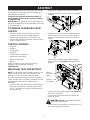 4
4
-
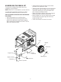 5
5
-
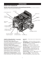 6
6
-
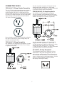 7
7
-
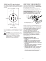 8
8
-
 9
9
-
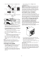 10
10
-
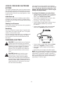 11
11
-
 12
12
-
 13
13
-
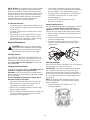 14
14
-
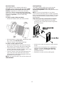 15
15
-
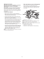 16
16
-
 17
17
-
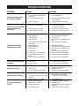 18
18
-
 19
19
-
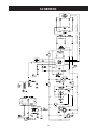 20
20
-
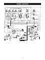 21
21
-
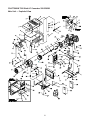 22
22
-
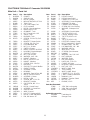 23
23
-
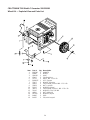 24
24
-
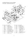 25
25
-
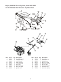 26
26
-
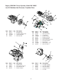 27
27
-
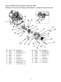 28
28
-
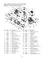 29
29
-
 30
30
-
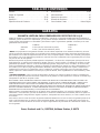 31
31
-
 32
32
-
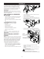 33
33
-
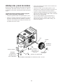 34
34
-
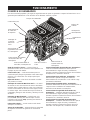 35
35
-
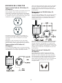 36
36
-
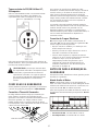 37
37
-
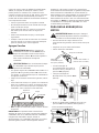 38
38
-
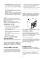 39
39
-
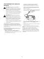 40
40
-
 41
41
-
 42
42
-
 43
43
-
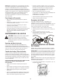 44
44
-
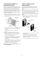 45
45
-
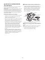 46
46
-
 47
47
-
 48
48
-
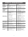 49
49
-
 50
50
-
 51
51
-
 52
52


Crafstman 01527-0 Manual de usuario
- Categoría
- Generadores de poder
- Tipo
- Manual de usuario
- Este manual también es adecuado para
En otros idiomas
- English: Crafstman 01527-0 User manual
Documentos relacionados
Otros documentos
-
Craftsman 580329180 El manual del propietario
-
Simplicity 01187-0 Manual de usuario
-
-
-
-
-
-
-
-