
MODELO 655/655MX/659 CALENTADOR/
VENTILADOR/LUZ
MODELO 657 VENTILADOR/LUZ
PAQUETES DE ACABADO 655F, 657F, Y 659F
PARA USAR CON PAQUETES DE BASTIDOR 654H
LEA Y CONSERVE
ESTAS INSTRUCCIONES
FIG. 1
FIG. 2
FIG. 3
FIG. 4
FIG. 5
KNOCKOUTS
DISCOS
REMOVIBLES
RETAINING
SCREWS
TORNILLOS
DE RETEN
READ AND SAVE
THESE INSTRUCTIONS
MODEL 655/655MX/659 HEATER/
FAN/LIGHT
MODEL 657 FAN/LIGHT
655F, 657F AND 659F FINISH PACKS FOR
USE WITH 654H HOUSING PACKS
INSTALLER: Leave This Manual With The Homeowner. HOMEOWNER: Use and Care Information on Page 3.
INSTALADOR: Deje este manual con el dueño de casa. DUEÑO DE CASA: Información del uso y mantenimiento en la página 3.
WARNING
TO REDUCE THE RISK OF FIRE, ELECTRIC SHOCK,
OR INJURY TO PERSONS, OBSERVE THE FOL-
LOWING:
1. Installation work and electrical wiring must be done
by qualied person(s) in accordance with all ap-
plicable codes and standards, including re-rated
construction.
2. THIS PRODUCT MUST BE GROUNDED.
UNITS WITH HEATERS ONLY:
3. Do not use this unit with any solid-state speed
control device.
4. The combustion air ow needed for safe operation
of fuel-burning equipment may be affected by this
unit's operation. Follow the heating equipment
manufacturer's guideline and safety standards such
as those published by the National Fire Protection
Association (NFPA), and the American Society for
Heating, Refrigeration and Air Conditioning Engi-
neers (ASHRAE), and the local code authorities.
5. When cutting or drilling into wall or ceiling, do not
damage electrical wiring and other hidden utilities.
6. Ducted fans must always be vented to the out-
doors.
UNITS WITH HEATERS ONLY:
7. Do not install this unit in a tub or shower enclo-
sure.
8. Never place a switch where it can be reached from
a tub or shower.
9. Use this unit only in the manner intended by the
manufacturer. If you have questions, contact the
manufacturer.
10. Before servicing or cleaning unit, switch power off
at service panel and lock service panel to prevent
power from being switched on accidentally.
CAUTION
UNITS WITH HEATERS ONLY:
1. Provide a separate 15 AMP circuit. Use 14 GA.
power cable of type which meets code. (Separate
20 AMP circuit and 12 GA. wire for Model 655,
655MX.)
2. This product is designed for ceiling installation
only. This product is designed for installation in
ceilings up to a12/12 pitch. Ductwork must point
up. DO NOT MOUNT THIS PRODUCT IN A
WALL.
3. Install in ceiling only, at least 6" from any wall.
4. For greatest efciency, install heater so heat is
directed toward tub or shower area. Avoid direct-
ing toward walls or windows.
Models 657 & 657F ONLY:
5. Acceptable for use over a bathtub or shower
when installed in a GFCI protected branch
circuit.
6. For general ventilating use only. Do not use to
exhaust hazardous or explosive materials and
vapors.
7. To avoid motor bearing damage and noisy and/or
unbalanced impellers, keep drywall spray, construc-
tion dust, etc., off power unit.
8. Please read specication label on product for further
information and requirements.
ADVERTENCIA
PARA REDUCIR EL RIESGO DE INCENDIO, DESCARGA
ELECTRICA O LESIONES PERSONALES, CUMPLA CON
LOS SIGUIENTES PUNTOS:
1. El trabajo de instalación y el cableado eléctrico deben
de llevarse a cabo por personal competente de acuerdo
con todos los códigos y las normas correspondientes,
incluyendo los códigos y normas de construcción a
prueba de incendios.
2. ESTE PRODUCTO DEBE SER CONECTADO A
TIERRA.
SOLAMENTE PARA UNIDADES CON CALENTADOR:
3. No utilice esta unidad con aparatos de estado sólido
de control de velocidad.
4. El ujo de aire para la combustión necesario para
el funcionamiento seguro de equipo que quema
combustible puede ser afectado por el funcionamiento
de esta unidad. Siga las especicaciones del fabricante
del equipo de calefacción y las normas de seguridad
semejantes a las publicadas por la Asociación Nacional
de Protección Contra Incendios (NFPA por sus siglas
en inglés), y la Sociedad Americana de Ingenieros
de Calefacción, Refrigeración y Aire Acondicionado
(ASHRAE), y los códigos de las autoridades locales.
5. Cuando corte o taladre en una pared o cielo raso, no dañe
los cables eléctricos ni otras instalaciones no visibles.
6. Los ventiladores con conductos siempre deben ventilar
hacia el exterior.
SOLAMENTE PARA UNIDADES CON CALENTADOR:
7. No instale esta unidad sobre una bañera o ducha.
8. Nunca coloque un interruptor donde pueda ser alcanzado
desde la bañera o la ducha.
9. Solamente use esta unidad de la manera propuesta
por el fabricante. Si tiene alguna pregunta, póngase en
contacto con el fabricante.
10. Antes de limpiar o reparar la unidad, corte la potencia en
el panel de servicio y asegúrelo para evitar que resuma
accidentalmente.
PRECAUCIÓN
SOLAMENTE PARA UNIDADES CON CALENTADOR:
1. Provea un circuito por separado de 15 AMP. Use un
cable de potencia 14 GA. del tipo conforme al código
(circuito por separado de 20 AMP y cable de 12 GA.
para el modelo 655, 655MX).
2. Este producto está diseñado solamente para instalarse
en el cielo raso. Este producto está diseñado para
instalarse en cielos rasos con una pendiente de
hasta 12/12. El sistema de conductos debe apuntar
hacia arriba. NO MONTE ESTE PRODUCTO EN LA
PARED.
3. Instalar en el techo solamente por lo menos a 6" de la
pared.
4. Para asegurar una mayor eficiencia, instale el
calentador de manera que el calor esté dirigido hacia
el área de la bañera o ducha. Evite dirigir el calor hacia
paredes o ventanas.
SOLAMENTE MODELOS 657 y 657F:
5. Aceptable si se lo usa por encima de una tina o ducha
instaladas en un circuito derivado protegido GFCI
(con interruptor accionado por corriente de pérdida a
tierra).
6. Solamente para uso de ventilación general. No use para
ventilar materiales y vapores peligrosos o explosivos.
7. Para evitar daños al cojinete del motor y/o impulsores
ruidosos o desequilibrados, mantenga la fuente
de potencia lejos de rocíos de yeso, de polvo de
construcción, etc.
8. Lea la etiqueta de especicaciones del producto para
más información y requisitos.
HINGE PIN
PASADORE DE
LA BISAGRA
To register this product visit
www.broan.com

FIG. 6
FIG. 7
FIG. 8
EMBOSSED
MEASURING
GUIDES
GUIAS ESTAM-
PADAS DE
MEDICION
FIG. 9
FLUSH
NIVEL
NOTE
NOTA
WIRE
OPENING
ENTRADA
PARA
EL CABLE
RELEASE SLOT
RANURA DE
DESENGANCHE
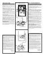
If the switch has not been wired properly and wires need to
be moved:
1. Each wire opening has a release slot.
2. Push a small nail or screwdriver into release slot while gently
removing wire.
3. DO NOT pull any wire out of the switch without using the release
slot. The switch may be damaged.
Si el interruptor no ha sido conectado de forma apropiada y
se necesita cambiar los cables:
1. Cada entrada para cable posee una ranura de desenganche.
2. Meta un clavo pequeño o un destornillador en la ranura de
desenganche mientras saca el cable poco a poco.
3. NO tire de los cables hacia afuera del interruptor sin usar la
ranura de desenganche. Esto puede dañar el interruptor.
PREPARACION
DE LA UNIDAD
PASOS DEL 1 AL 3 - SOLO PARA
UNIDADES CON CALENTADORES
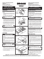
1. Asegúrese de que el conjunto del calentador está
desconectado del enchufe ROJO.
2. Afloje los dos tornillo de retén en el interior de la
abertura de descarga del calentador. Coloque la punta
del destornillador entre la pared exterior de la abertura
de descarga y la caja del ventilador. Haga palanca
suavemente hacia afuera hasta que la abertura del escape
se deslice del borde de apoyo en la caja exterior. (FIG.
1)
3. Desenganche los pasadores de la bisagra y levante el
conjunto del calentador hacia afuera de la caja. (FIG. 2)
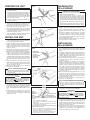
4. Desconecte el conjunto del ventilador del enchufe
NEGRO. Saque la bolsa de plástico y déjela a un lado.
5. Saque el tornillo de montaje y levante con cuidado el
conjunto del ventilador hacia afuera de la caja. (FIG.
3)
6. Refiérase al diagrama de conexiones de la unidad
en la página siguiente. Saque los discos removibles
apropiados introduciendo la punta del destornillador
en las ranuras y moviendo éste de un lado a otro hasta
romper las lengüetas. (FIG. 4)
7. Meta los soportes de montaje ajustables en los canales
para los soportes en la caja. (FIG. 5)
INSTALACION
DE LA UNIDAD
8. Para mejores resultados, elija una posición que permita
que el ventilador extraiga hacia afuera usando la
menor cantidad de ducto y el menor número posible de
codos.
9. Coloque la unidad entre las vigas y extienda los soportes
de montaje. Coloque los soportes de manera que el
extremo inferior de la caja esté al nivel del cielo raso
acabado. Marque la parte superior de la ranura en los
cuatro soportes de montaje. (FIG. 5)
10. Saque la unidad por unos momentos, y clave los clavos
parcialmente en las vigas en las cuatro posiciones
marcadas. (FIG. 7)
11. Cuelgue la unidad de los clavos y use las guías de
medición estampadas para comprobar si la unidad se
encuentra a nivel con el cielo raso acabado. Termine de
clavar los clavos. En caso de que el centro de las vigas
sea ancho: se puede usar un tornillo autoenroscante #
8 x 3/8 para juntar los soportes extendidos y crear un
soporte de montaje rígido. Para asegurar un montaje
silencioso, pliegue los canales alrededor de los soportes
de montaje. (FIG. 8)
12. Meta la conexión del amortiguador/ducto en la caja.
Asegúrese de que las lengüetas del conector se
cierran en las ranuras de la caja.(La parte superior
del amortiguador/ducto debe estar a nivel con la parte
superior de la caja). (FIG. 9)
13. Conecte la unidad de acuerdo con el diagrama de las
guras 10 y 11. (See NOTE.)
PASO 14 - SOLO PARA UNIDADES CON CALENTADORES
14. Vuelva a colocar el conjunto del calentador que se
sacó en el paso 3 y conéctelo al enchufe ROJO.
Instale los alambres alejados de la entrada de aire el
ventilador.
15. Vuelva a colocar el conjunto del ventilador que se sacó
en el paso 5 y conéctelo al enchufe NEGRO.
PRECAUCION
Para evitar la posibilidad de un sobrecalentamiento
y/o un incendio, la rejilla debe ser instalada se mues-
tra en la figura 12. La tuerca ciega debe conectarse
a la varilla roscada a través del agujero apropiado
en el reflector de luz.
16. Deslice el reector de luz en la abertura de la rejilla y
conéctelo al enchufe BLANCO. Use la tuerca en la bolsa
de plástico para sujetar la rejilla y el reector de luz a la
varilla roscada de la caja. Apriete con fuerza usando el
alicates o el aprietatuercas. Instale una bombilla de un
máximo de 100 vatios. (FIG. 12)
17. Para instalar el lente de la luz: 1) Enganche una de las
lengüetas en la muesca del conjunto rejilla/reector; 2)
Aplique un poco de presión a la otra lengûeta con los
dedos, y 3) Encájela en su sitio. (FIG. 13)
2
PREPARE THE UNIT
STEPS 1 THRU 3 - UNITS WITH HEATERS ONLY
1. Make sure the heater assembly is unplugged from
the RED receptacle.
2. Loosen the two retaining screws on the inside of
the heater discharge opening. Place a screwdriver
tip between the outer wall of the discharge open-
ing and the fan housing. Gently pry outward until
the exhaust discharge slips off the support lip on
the outer housing. (FIG. 1)
3. Unhook hinge pins and lift heater assembly out
of housing. (FIG. 2)
4. Unplug the fan assembly from the BLACK recep-
tacle. Remove the plastic bag and set it aside.
5. Remove the mounting screw and carefully lift the
fan assembly out of the housing. (FIG. 3)
6. Refer to the wiring diagram of your unit on the next
page. Remove appropriate knockout(s) by inserting
a screwdriver blade into slots and bending it back
and forth to break tabs. (FIG. 4)
7. Insert the adjustable mounting brackets into the
bracket channels on the housing. (FIG. 5)
INSTALL THE UNIT
8. For best results, choose a location which allows fan
to be vented outside with the shortest possible duct
run and the fewest number of elbows.
9. Position unit between joists and extend mounting
brackets. Position brackets such that the bottom
edge of housing will be ush with nished ceiling.
Mark the top of keyhole slot on all four mounting
brackets. (FIG. 6)
10. Remove unit temporarily, and pound nails partially
into joists at all four marked locations. (FIG. 7)
11. Hang unit from nails and use embossed measuring
guides to check if unit will be ush with nished
ceiling. Pound nails tight. For wide joist centers:
A #8 x 3/8 self-tapping screw can be used to join
extended brackets together and create a rigid mount.
To ensure a noise-free mount, crimp the bracket
channels tightly around mounting brackets. (FIG.
8)
12. Snap the damper/duct connector onto housing.
Make sure that tabs on the connector lock in housing
slots. (Top of damper/duct connector will be ush
with top of housing.) (FIG. 9)
13. Wire unit according to Figure 10 or 11, whichever
is appropriate. (See NOTE.)
STEP 14 - UNITS WITH HEATERS ONLY
14. Replace heater assembly removed in STEP 3
and plug it into RED receptacle. Direct wires away
from blower inlet.
15. Replace fan assembly removed in STEP 5 and plug
it into BLACK receptacle.
CAUTION
To avoid the possibility of overheating and/or
fire, the grille must be installed as shown in
FIG. 12. Acorn nut must attach to threaded rod
through proper hole in light reflector.
16. Slide the light reector into opening in grille and plug
into WHITE receptacle. Use acorn nut from plastic
bag to attach grille reector assembly to threaded
rod on housing. Tighten securely using pliers or nut
driver. Install a light bulb 100 Watt maximum. (FIG..
12)
17. Install light lens by 1) hooking one of its tabs into
notch in grille/reector assembly; 2) apply light
pressure to other tab with ngertips and 3) snap
into place. (FIG. 13)

FIG. 10 MODEL 655, 655MX, 659
LIGHT
LUZ
VENT
RESPI-
RADERO
WHITE
BLANCO
GRD
TIERRA
120 VAC LINE IN
LINEA DE ENTRADA DE
120VCA
BLACK
NEGRO
WHITE
BLANCO
BLACK
NEGRO
GRD
TIERRA
RED
ROJO
BLUE
AZUL
FIG. 11 MODEL 657
USE AND CARE
DISCONNECT ELECTRIC POWER SUPPLY BEFORE
CLEANING OR SERVICING THIS UNIT.
TO REPLACE BULB - Remove lens by gently depress-
ing sides and pull down. Use bulb rated up to 100
watts only.
TO CLEAN LENS AND GRILLE - Remove lens as
explained above. Remove bulb. Remove acorn nut in
center of reector and lower assembly.
CAUTION: Grille and reector are separate units.
Unplug light from white receptacle. Plastic parts can
be cleaned with mild, soapy water and dried with soft
cloth. DO NOT USE ABRASIVE CLOTHS, STEEL
WOOL PADS, OR SCOURING POWDERS.
TO CLEAN FAN ASSEMBLY - Unplug fan motor cord
from black receptacle. Remove retaining screw located
near receptacle. See FIG. 3.
CAUTION: Fan and motor will swing downward when
screw is removed. Support this unit with free hand while
removing retaining screw.
Gently vacuum fan, motor and interior of housing. Motor
is permanently lubricated - never needs oiling.
TO CLEAN HEATER ASSEMBLY - Unplug heater cord
from red receptacle. Loosen retaining screws. Place a
screwdriver tip between outer wall of housing and heater
exhaust opening. Gently pry outward until exhaust
housing slips off support tip. See FIG. 1.
CAUTION: Unit will swing downward when released.
Support with free hand while prying with screwdriver.
Gently vacuum blower, motor and interior of housing.
Motor is permanently lubricated - never needs oiling.
METAL AND ELECTRICAL PARTS SHOULD NEVER
BE IMMERSED IN WATER.
TO REASSEMBLE ALL ABOVE PARTS - Reverse all
procedures explained above. Be sure hinge pins are
in place when reassembling fan and heater units. (See
FIG. 2.) Assemblies should not be disassembled any
further than explained above.
USO Y MANTENIMIENTO
DESCONECTE LA FUENTE DE ENERGIA ELECTRICA
ANTES DE LIMPIAR O DAR SERVICIO A ESTA UNIDAD.
PARA REEMPLAZAR LA LAMPARA: Quite el lente, presion-
ando suavemente los lados y empuje. Use una bombilla de
una capacidad nominal máxima de 100 vatios.
PARA LIMPIAR EL LENTE Y LA REJILLA: saque el lente
como se explica arriba. Saque la bombilla. Saque la tuerca
ciega del centro del reector y baje el
conjunto.
PRECAUCION: la rejilla y el reector son unidades separa-
das. Desconecte la luz del enchufe blanco. Las piezas de
plástico se pueden limpiar con agua enjabonada y secadas
con un trapo suave. NO USE TELAS ÁSPERAS, ESPONJIL-
LAS DE LANA DE ACERO, O POLVOS ÁSPEROS.
PARA LIMPIAR EL CONJUNTO DEL VENTILADOR:
desconecte el cable de potencia del ventilador del enchufe
negro. Saque el tornillo de retén situado cerca del enchufe.
Vea FIG. 3.
PRECAUCION: El ventilador y el motor se vendrán un poco
hacia adelante cuando saque el tornillo. Sujete la unidad
con una mano mientras saca el tornillo de retén. Con una
aspiradora aspire suavemente el ventilador, motor e interior
de la caja. El motor está permanentemente lubricado - nunca
necesita lubricación.
PARA LIMPIAR EL CONJUNTO DEL CALENTADOR: desco-
necte el cable de potencia del enchufe rojo. Aoje los tornillos
de retén. Coloque la punta del destornillador entre la pared
exterior de la caja y la abertura de escape del calentador.
Haga palanca suavemente hasta que el escape de la caja
se deslice sobre la punta de soporte. Vea FIG. 1.
PRECAUCION: El ventilador y el motor se vendrán un poco
hacia adelante cuando saque el tornillo. Sujete la unidad con
una mano mientras hace palanca con el destornillador. Con
una aspiradora aspire suavemente el ventilador, motor e
interior de la caja. El motor está permanentemente lubricado
- nunca necesita lubricación.
EL METAL Y LAS PIEZAS ELECTRICAS NUNCA DE-
BEN SER SUMERGIDAS EN AGUA.
PARA VOLVER A ENSAMBLAR LAS PIEZAS MENCIO-
NADAS ARRIBA: Efectúe los procedimientos al revés.
Asegúrese de que los pasadores de las bisagras están en su
sitio cuando vuelva a ensamblar el ventilador y el calentador.
(Vea FIG. 2). Los conjuntos no deben ser desmontados más
de lo que se explica arriba.
BROAN-NUTONE ONE YEAR LIMITED WARRANTY
Broan-NuTone warrants to the original consumer purchaser of its
products that such products will be free from defects in materials
or workmanship for a period of one year from the date of original
purchase. THERE ARE NO OTHER WARRANTIES, EXPRESS OR
IMPLIED, INCLUDING, BUT NOT LIMITED TO, IMPLIED WARRAN-
TIES OR MERCHANT ABILITY OR FITNESS FOR A PARTICULAR
PURPOSE.
During this one-year period, Broan-NuTone will, at its option, repair
or replace, without charge, any product or part which is found to be
defective under normal use and service.
THIS WARRANTY DOES NOT EXTEND TO FLUORESCENT LAMP
STARTERS AND TUBES. This warranty does not cover (a) normal
maintenance and service or (b) any products or parts which have been
subject to misuse, negligence, accident, improper maintenance or repair
(other than by Broan-NuTone), faulty installation or installation contrary
to recommended installation instructions.
The duration of any implied warranty is limited to the one-year period
as specied for the express warranty. Some states do not allow limi-
tation on how long an implied warranty lasts, so the above limitation
may not apply to you.
BROAN-NUTONE’S OBLIGATION TO REPAIR OR REPLACE, AT
BROAN-NUTONE’S OPTION, SHALL BE THE PURCHASER’S SOLE
AND EXCLUSIVE REMEDY UNDER THIS WARRANTY. BROAN-NU-
TONE SHALL NOT BE LIABLE FOR INCIDENTAL, CONSEQUENTIAL
OR SPECIAL DAMAGES ARISING OUT OF OR IN CONNECTION
WITH PRODUCT USE OR PERFORMANCE. Some states do not allow
the exclusion or limitation of incidental or consequential damages, so
the above limitation or exclusion may not apply to you.
This warranty gives you specic legal rights, and you may also have
other rights, which vary from state to state. This warranty supersedes
all prior warranties.
To qualify for warranty service, you must (a) notify Broan-NuTone at the
address stated below or telephone: 1-800-637-1453, (b) give the model
number and part identication and (c) describe the nature of any defect
in the product or part. At the time of requesting warranty service, you
must present evidence of the original purchase date.
Broan-NuTone LLC
926 West State Street
Hartford, WI 53027
(1-800-637-1453)
GARANTIA BROAN-NUTONE LIMITADA POR UN AÑO
Broan-NuTone garantiza al consumidor comprador original de sus productos
que dichos productos carecerán de defectos en materiales o en mano de obra
por un período de un año a partir de la fecha original de compra. NO EXISTEN
OTRAS GARANTIAS, EXPLICITAS O IMPLICITAS, INCLUYENDO, PERO
NO LIMITADAS A, GARANTIAS IMPLICITAS DE COMERCIALIZACION O
APTITUD PARA UN PROPOSITO PARTICULAR.
Durante el período de un año, y a su propio criterio, Broan-NuTone reparará
o reemplazará, sin costo alguno cualquier producto o pieza que se encuentre
defectuosa bajo condiciones normales de servicio y uso.
ESTA GARANTIA NO SE APLICA A TUBOS Y ARRANCADORES DE
LAMPARAS
FLUORESCENTES. Esta garantía no cubre (a) mantenimiento y servicio
normales o (b) cualquier producto o piezas que hayan sido utilizadas de
forma errónea, negligente, que hayan causado un accidente, o que hayan
sido reparadas o mantenidas inapropiadamente (por otras compañías que
no sean Broan-NuTone), instalación defectuosa, o instalación contraria a las
instrucciones de instalación recomendadas.
La duración de cualquier garantía implícita se limita a un período de un año
como se especica en la garantía expresa. Algunos estados no permiten
limitaciones en cuanto al tiempo de expiración de una garantía implícita, por
lo que la limitación antes mencionada puede no aplicarse a usted.
LA OBLIGACION DE BROAN-NUTONE DE REPARAR O REEMPLAZAR,
SIGUIENDO EL CRITERIO DE BROAN-NUTONE, DEBERA SER EL UNICO
Y EXCLUSIVO RECURSO LEGAL DEL COMPRADOR BAJO ESTA GARAN-
TIA. BROAN-NUTONE NO SERA RESPONSABLE POR DAÑOS INCIDEN-
TALES, CONSIGUIENTES, O POR DAÑOS ESPECIALES QUE SURJAN
A RAIZ DEL USO O DESEMPEÑO DEL PRODUCTO. Algunos estados no
permiten la exclusión o limitación de daños incidentales o consiguientes, por
lo que la limitación antes mencionada puede no aplicarse a usted.
Esta garantía le proporciona derechos legales especícos, y usted puede
también tener otros derechos, los cuales varían de estado a estado. Esta
garantía reemplaza todas las garantías anteriores.
Para calicar en la garantía de servicio, usted debe (a) noticar a Broan-
NuTone al domicilio que se menciona abajo o al teléfono:1-800-637-1453,
(b) dar el número del modelo y la identicación de la pieza, y (c) describir la
naturaleza de cualquier defecto en el producto o pieza. En el momento de
solicitar servicio cubierto por la garantía, usted debe de presentar evidencia
de la fecha original de compra.
Broan-NuTone LLC
926 West State Street
Hartford, WI 53027
(1-800-637-1453)
BLACK
NEGRO
RED/ROJO
3
RED / ROJO
WHITE
BLANCO
BLACK
NEGRO
120 VAC LINE IN
LINEA DE ENTRADA DE 120 VCA
LIGHT
LUZ
VENT
RESPI-
RADERO
HEAT
CALOR
GROUND
TIERRA
RED
ROJO
BLACK
NEGRO
GROUND
TIERRA
RED
ROJO
BLUE
AZUL
WHITE
BLANCO
BLACK
NEGRO

GROUND (GREEN OR
BARE WIRE)
TIERRA (CABLE
VERDE O
DESCUBIERTO)
GROUNDING CLIP
CLIP DE TIERRA
GROUNDING DETAIL 657 ONLY
DETALLE DE LA TOMA DE TIERRA
SOLO PARA EL 657
FIG. 12
FIG. 13
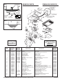
SERVICE PARTS
MODELS 655, 655MX, 657 & 659
PIEZAS DE SERVICIO
MODELOS 655, 655MX, 657 y 659
NOTCH / MUESCA
Broan-NuTone LLC, 926 West State Street, Hartford, WI 53027 (1-800-637-1453)
KEY NO. MODEL 655/655Mx MODEL 657 MODEL 659
NO. PART NO. PART NO. PART NO.
CODIGO MODELO 655/655Mx MODELO 657 DESCRIPTION DESCRIPCION MODELO 659
NO. PIEZ NO. PIEZ NO. PIEZ
1 97007543 97007543 Housing Caja 97007543
2 97014185 97014185 Damper Amortiguador 97003932
3 98003036 98003036 Mounting Bracket (4 Req.) Ménsula de montaje (se necesitan 4) 98003036
4 99270981 99270981 Receptacle, White Enchufe - Blanco 99270981
5 99270982 99270982 Receptacle, Black Enchufe - Negro 99270982
6 99270489 ----- Receptacle, Red Enchufe - Rojo 99270489
7 99110446 99110446 Plastic Blower Wheel Disco de plástico del soplador 99111002
8 99080166 99080166 Fan Motor Motor del ventilador 97012038
9 97013627 97013627 Motor Plate / Partition Assembly Placa del motor/Conjunto del espaciador 97013627
10 99260428 99260428 Nut (4 Req.) Tuerca (se necesitan 4) 99260428
11 97013836 97013836 Grille Rejilla 97013836
12 97014211 97014211 Light Reector Reector de luz 97014211
13 97005316 97005316 Nut Tuerca 97005316
14 99770118 99770118 Light Socket Cubo de la bombilla 99770029
15 97013578 97013578 Light Lens Lente de la luz 97013578
16 97005058 ----- Bolt Assembly Conjunto de tornillos 97005058
17 99020290 ----- Blower Wheel Disco del soplador 99020290
18 99160422 ----- Screw, #10-32 x .375 (2 Req.) Tornillo, #10-32 x .375 (se necesitan 2) 99160422
19 93260457 -----
#10 - 32 Nut (7 Req.) (2 included in Key No. 16) Tuerca #10-32 (se necesitan 7) (2 incluyeron en no. código 16)
93260457
20 99270107 ----- Heater Hooks (5 Req.) Ganchos del calentador (se necesitan 5) 99270107
21 99150417 ----- #8 x 1/4 Sheet Metal Screws (4 Req.)
Tornillos de lámina de metal #8 x 1/4 (se necesitan 4)
99150417
22 98003788 ----- Heater Scroll Cover Cubierta de la espiral del calentador 98003788
23 97005006 ----- Heater Scroll Housing Caja de la espiral del calentador 97005006
24 99080591 ----- Heater Motor Motor del calentador 99080591
25 99170245 99170245 #8 x 3/8 Sheet Metal Screw Tornillo de lámina de metal #8 x 3/8 99170245
26 99160410 99160410 Grille Stud Pasador de la rejilla 99160410
27 98004514 ----- Heater Element Elemento del calentador 98004514
28 99260566 ----- Tinnerman Nut #10-32 (2 Req.) Tuerca Tinnerman #10 x 32 (se necesitan 2) 99260566
29 ----- 98000566 Aluminum Receptacle Plug Conexión del enchufe de aluminio -----
30 ----- 99390015 Grounding Clip Clip de tierra -----
Order service parts by "Part No. - Not by "Key No." Encargue piezas de reemplazo por No. Pieza - NO por No. Código.
99043687D
2
3
1
THREADED ROD
VARILLA ROSCADA
LIGHT REFLEC-
TOR
REFLECTOR
DE LUZ
ACORN NUT
TUERCA CIEGA
GRILLE
REJILLA
USE THIS HOLE
USE ESTE AGUJERO
BOTTOM VIEW
VISTA INFERIOR
25
Replacement parts
can now be ordered
on our website.
Please visit us at
www.Broan.com
Las piezas de recambio
se pueden ahora pedir en
nuestro Web site. Visítenos
por favor en
www.Broan.com
Transcripción de documentos
MODEL 655/655MX/659 HEATER/ FAN/LIGHT MODEL 657 FAN/LIGHT To register this product visit www.broan.com 655F, 657F AND 659F FINISH PACKS FOR USE WITH 654H HOUSING PACKS Read and Save These Instructions UNITS WITH HEATERS ONLY: 3. Do not use this unit with any solid-state speed control device. 4. The combustion air flow needed for safe operation of fuel-burning equipment may be affected by this unit's operation. Follow the heating equipment manufacturer's guideline and safety standards such as those published by the National Fire Protection Association (NFPA), and the American Society for Heating, Refrigeration and Air Conditioning Engineers (ASHRAE), and the local code authorities. 5. When cutting or drilling into wall or ceiling, do not damage electrical wiring and other hidden utilities. 6. Ducted fans must always be vented to the outdoors. UNITS WITH HEATERS ONLY: 7. Do not install this unit in a tub or shower enclosure. 8. Never place a switch where it can be reached from a tub or shower. 9. Use this unit only in the manner intended by the manufacturer. If you have questions, contact the manufacturer. 10. Before servicing or cleaning unit, switch power off at service panel and lock service panel to prevent power from being switched on accidentally. Fig. 1 Advertencia PARA REDUCIR EL RIESGO DE INCENDIO, DESCARGA ELECTRICA O LESIONES PERSONALES, CUMPLA CON LOS SIGUIENTES PUNTOS: 1. El trabajo de instalación y el cableado eléctrico deben de llevarse a cabo por personal competente de acuerdo con todos los códigos y las normas correspondientes, incluyendo los códigos y normas de construcción a prueba de incendios. 2. ESTE PRODUCTO DEBE SER CONECTADO A TIERRA. SOLAMENTE PARA UNIDADES CON CALENTADOR: 3. No utilice esta unidad con aparatos de estado sólido de control de velocidad. RETAINING SCREWS tornillos de reten FIG. 2 HINGE PIN pasadore de la bisagra 4. El flujo de aire para la combustión necesario para el funcionamiento seguro de equipo que quema combustible puede ser afectado por el funcionamiento de esta unidad. Siga las especificaciones del fabricante del equipo de calefacción y las normas de seguridad semejantes a las publicadas por la Asociación Nacional de Protección Contra Incendios (NFPA por sus siglas en inglés), y la Sociedad Americana de Ingenieros de Calefacción, Refrigeración y Aire Acondicionado (ASHRAE), y los códigos de las autoridades locales. 5. Cuando corte o taladre en una pared o cielo raso, no dañe los cables eléctricos ni otras instalaciones no visibles. 6. Los ventiladores con conductos siempre deben ventilar hacia el exterior. SOLAMENTE PARA UNIDADES CON CALENTADOR: 7. No instale esta unidad sobre una bañera o ducha. 8. Nunca coloque un interruptor donde pueda ser alcanzado desde la bañera o la ducha. 9. Solamente use esta unidad de la manera propuesta por el fabricante. Si tiene alguna pregunta, póngase en contacto con el fabricante. 10. Antes de limpiar o reparar la unidad, corte la potencia en el panel de servicio y asegúrelo para evitar que resuma accidentalmente. FIG. 3 CAUTION UNITS WITH HEATERS ONLY: 1. Provide a separate 15 AMP circuit. Use 14 GA. power cable of type which meets code. (Separate 20 AMP circuit and 12 GA. wire for Model 655, 655MX.) 2. This product is designed for ceiling installation only. This product is designed for installation in ceilings up to a12/12 pitch. Ductwork must point up. DO NOT MOUNT THIS PRODUCT IN A WALL. 3. Install in ceiling only, at least 6" from any wall. 4. For greatest efficiency, install heater so heat is directed toward tub or shower area. Avoid directing toward walls or windows. Precaución FIG. 4 Models 657 & 657F ONLY: 5. Acceptable for use over a bathtub or shower when installed in a GFCI protected branch circuit. 6. For general ventilating use only. Do not use to exhaust hazardous or explosive materials and vapors. 7. To avoid motor bearing damage and noisy and/or unbalanced impellers, keep drywall spray, construction dust, etc., off power unit. 8. Please read specification label on product for further information and requirements. Paquetes de acabado 655F, 657F, y 659F para usar con paquetes de bastidor 654H Lea Y Conserve Estas Instrucciones WARNING TO REDUCE THE RISK OF FIRE, ELECTRIC SHOCK, OR INJURY TO PERSONS, OBSERVE THE FOLLOWING: 1. Installation work and electrical wiring must be done by qualified person(s) in accordance with all applicable codes and standards, including fire-rated construction. 2. THIS PRODUCT MUST BE GROUNDED. Modelo 655/655MX/659 Calentador/ Ventilador/Luz Modelo 657 Ventilador/Luz FIG. 5 KNOCKOUTS discos removibles SOLAMENTE PARA UNIDADES CON CALENTADOR: 1. Provea un circuito por separado de 15 AMP. Use un cable de potencia 14 GA. del tipo conforme al código (circuito por separado de 20 AMP y cable de 12 GA. para el modelo 655, 655MX). 2. Este producto está diseñado solamente para instalarse en el cielo raso. Este producto está diseñado para instalarse en cielos rasos con una pendiente de hasta 12/12. El sistema de conductos debe apuntar hacia arriba. NO MONTE ESTE PRODUCTO EN LA PARED. 3. Instalar en el techo solamente por lo menos a 6" de la pared. 4. Para asegurar una mayor eficiencia, instale el calentador de manera que el calor esté dirigido hacia el área de la bañera o ducha. Evite dirigir el calor hacia paredes o ventanas. SOLAMENTE MODELOS 657 y 657F: 5. Aceptable si se lo usa por encima de una tina o ducha instaladas en un circuito derivado protegido GFCI (con interruptor accionado por corriente de pérdida a tierra). 6. Solamente para uso de ventilación general. No use para ventilar materiales y vapores peligrosos o explosivos. 7. Para evitar daños al cojinete del motor y/o impulsores ruidosos o desequilibrados, mantenga la fuente de potencia lejos de rocíos de yeso, de polvo de construcción, etc. 8. Lea la etiqueta de especificaciones del producto para más información y requisitos. INSTALLER: Leave This Manual With The Homeowner. HOMEOWNER: Use and Care Information on Page 3. INSTALADOR: Deje este manual con el dueño de casa. DUEÑO DE CASA: Información del uso y mantenimiento en la página 3. PREPARE THE UNIT STEPS 1 THRU 3 - UNITS WITH HEATERS ONLY 1. Make sure the heater assembly is unplugged from the RED receptacle. 2. Loosen the two retaining screws on the inside of the heater discharge opening. Place a screwdriver tip between the outer wall of the discharge opening and the fan housing. Gently pry outward until the exhaust discharge slips off the support lip on the outer housing. (FIG. 1) 3. Unhook hinge pins and lift heater assembly out of housing. (FIG. 2) 4. Unplug the fan assembly from the BLACK receptacle. Remove the plastic bag and set it aside. 5. Remove the mounting screw and carefully lift the fan assembly out of the housing. (FIG. 3) 6. Refer to the wiring diagram of your unit on the next page. Remove appropriate knockout(s) by inserting a screwdriver blade into slots and bending it back and forth to break tabs. (FIG. 4) 7. Insert the adjustable mounting brackets into the bracket channels on the housing. (FIG. 5) PREPARACION DE LA UNIDAD FIG. 6 PASOS DEL 1 AL 3 - SOLO PARA UNIDADES CON CALENTADORES 1. Asegúrese de que el conjunto del calentador está desconectado del enchufe ROJO. 2. Afloje los dos tornillo de retén en el interior de la abertura de descarga del calentador. Coloque la punta del destornillador entre la pared exterior de la abertura de descarga y la caja del ventilador. Haga palanca suavemente hacia afuera hasta que la abertura del escape se deslice del borde de apoyo en la caja exterior. (FIG. 1) 3. Desenganche los pasadores de la bisagra y levante el conjunto del calentador hacia afuera de la caja. (FIG. 2) 4. Desconecte el conjunto del ventilador del enchufe NEGRO. Saque la bolsa de plástico y déjela a un lado. 5. Saque el tornillo de montaje y levante con cuidado el conjunto del ventilador hacia afuera de la caja. (FIG. 3) 6. Refiérase al diagrama de conexiones de la unidad en la página siguiente. Saque los discos removibles apropiados introduciendo la punta del destornillador en las ranuras y moviendo éste de un lado a otro hasta romper las lengüetas. (FIG. 4) 7. Meta los soportes de montaje ajustables en los canales para los soportes en la caja. (FIG. 5) FIG. 7 INSTALL THE UNIT 8. For best results, choose a location which allows fan to be vented outside with the shortest possible duct run and the fewest number of elbows. 9. Position unit between joists and extend mounting brackets. Position brackets such that the bottom edge of housing will be flush with finished ceiling. Mark the top of keyhole slot on all four mounting brackets. (FIG. 6) 10. Remove unit temporarily, and pound nails partially into joists at all four marked locations. (FIG. 7) 11. Hang unit from nails and use embossed measuring guides to check if unit will be flush with finished ceiling. Pound nails tight. For wide joist centers: A #8 x 3/8 self-tapping screw can be used to join extended brackets together and create a rigid mount. To ensure a noise-free mount, crimp the bracket channels tightly around mounting brackets. (FIG. 8) 12. Snap the damper/duct connector onto housing. Make sure that tabs on the connector lock in housing slots. (Top of damper/duct connector will be flush with top of housing.) (FIG. 9) 13. Wire unit according to Figure 10 or 11, whichever is appropriate. (See NOTE.) STEP 14 - UNITS WITH HEATERS ONLY 14. Replace heater assembly removed in STEP 3 and plug it into RED receptacle. Direct wires away from blower inlet. 15. Replace fan assembly removed in STEP 5 and plug it into BLACK receptacle. INSTALACION DE LA UNIDAD 8. Para mejores resultados, elija una posición que permita que el ventilador extraiga hacia afuera usando la menor cantidad de ducto y el menor número posible de codos. 9. Coloque la unidad entre las vigas y extienda los soportes de montaje. Coloque los soportes de manera que el extremo inferior de la caja esté al nivel del cielo raso acabado. Marque la parte superior de la ranura en los cuatro soportes de montaje. (FIG. 5) 10. Saque la unidad por unos momentos, y clave los clavos parcialmente en las vigas en las cuatro posiciones marcadas. (FIG. 7) 11. Cuelgue la unidad de los clavos y use las guías de medición estampadas para comprobar si la unidad se encuentra a nivel con el cielo raso acabado. Termine de clavar los clavos. En caso de que el centro de las vigas sea ancho: se puede usar un tornillo autoenroscante # 8 x 3/8 para juntar los soportes extendidos y crear un soporte de montaje rígido. Para asegurar un montaje silencioso, pliegue los canales alrededor de los soportes de montaje. (FIG. 8) 12. Meta la conexión del amortiguador/ducto en la caja. Asegúrese de que las lengüetas del conector se cierran en las ranuras de la caja.(La parte superior del amortiguador/ducto debe estar a nivel con la parte superior de la caja). (FIG. 9) 13. Conecte la unidad de acuerdo con el diagrama de las figuras 10 y 11. (See NOTE.) FIG. 8 EMBOSSED MEASURING GUIDES guias estampadas de medicion FIG. 9 FLUSH nivel CAUTION To avoid the possibility of overheating and/or fire, the grille must be installed as shown in FIG. 12. Acorn nut must attach to threaded rod through proper hole in light reflector. 16. Slide the light reflector into opening in grille and plug into WHITE receptacle. Use acorn nut from plastic bag to attach grille reflector assembly to threaded rod on housing. Tighten securely using pliers or nut driver. Install a light bulb 100 Watt maximum. (FIG.. 12) 17. Install light lens by 1) hooking one of its tabs into notch in grille/reflector assembly; 2) apply light pressure to other tab with fingertips and 3) snap into place. (FIG. 13) PASO 14 - SOLO PARA UNIDADES CON CALENTADORES 14. Vuelva a colocar el conjunto del calentador que se sacó en el paso 3 y conéctelo al enchufe ROJO. Instale los alambres alejados de la entrada de aire el ventilador. NOTE NOTA WIRE OPENING entrada para el cable 15. Vuelva a colocar el conjunto del ventilador que se sacó en el paso 5 y conéctelo al enchufe NEGRO. RELEASE SLOT ranura de desenganche If the switch has not been wired properly and wires need to be moved: 1. 2. Each wire opening has a release slot. Push a small nail or screwdriver into release slot while gently removing wire. 3. DO NOT pull any wire out of the switch without using the release slot. The switch may be damaged. Si el interruptor no ha sido conectado de forma apropiada y se necesita cambiar los cables: 1. 2. 3. Cada entrada para cable posee una ranura de desenganche. Meta un clavo pequeño o un destornillador en la ranura de desenganche mientras saca el cable poco a poco. NO tire de los cables hacia afuera del interruptor sin usar la ranura de desenganche. Esto puede dañar el interruptor. 2 PRECAUCION Para evitar la posibilidad de un sobrecalentamiento y/o un incendio, la rejilla debe ser instalada se muestra en la figura 12. La tuerca ciega debe conectarse a la varilla roscada a través del agujero apropiado en el reflector de luz. 16. Deslice el reflector de luz en la abertura de la rejilla y conéctelo al enchufe BLANCO. Use la tuerca en la bolsa de plástico para sujetar la rejilla y el reflector de luz a la varilla roscada de la caja. Apriete con fuerza usando el alicates o el aprietatuercas. Instale una bombilla de un máximo de 100 vatios. (FIG. 12) 17. Para instalar el lente de la luz: 1) Enganche una de las lengüetas en la muesca del conjunto rejilla/reflector; 2) Aplique un poco de presión a la otra lengûeta con los dedos, y 3) Encájela en su sitio. (FIG. 13) USE AND CARE DISCONNECT ELECTRIC POWER SUPPLY BEFORE CLEANING OR SERVICING THIS UNIT. TO REPLACE BULB - Remove lens by gently depressing sides and pull down. Use bulb rated up to 100 watts only. TO CLEAN LENS AND GRILLE - Remove lens as explained above. Remove bulb. Remove acorn nut in center of reflector and lower assembly. CAUTION: Grille and reflector are separate units. Unplug light from white receptacle. Plastic parts can be cleaned with mild, soapy water and dried with soft cloth. DO NOT USE ABRASIVE CLOTHS, STEEL WOOL PADS, OR SCOURING POWDERS. TO CLEAN FAN ASSEMBLY - Unplug fan motor cord from black receptacle. Remove retaining screw located near receptacle. See FIG. 3. CAUTION: Fan and motor will swing downward when screw is removed. Support this unit with free hand while removing retaining screw. Gently vacuum fan, motor and interior of housing. Motor is permanently lubricated - never needs oiling. TO CLEAN HEATER ASSEMBLY - Unplug heater cord from red receptacle. Loosen retaining screws. Place a screwdriver tip between outer wall of housing and heater exhaust opening. Gently pry outward until exhaust housing slips off support tip. See FIG. 1. CAUTION: Unit will swing downward when released. Support with free hand while prying with screwdriver. Gently vacuum blower, motor and interior of housing. Motor is permanently lubricated - never needs oiling. METAL AND ELECTRICAL PARTS SHOULD NEVER BE IMMERSED IN WATER. TO REASSEMBLE ALL ABOVE PARTS - Reverse all procedures explained above. Be sure hinge pins are in place when reassembling fan and heater units. (See FIG. 2.) Assemblies should not be disassembled any further than explained above. FIG. 10 USO Y MANTENIMIENTO MODEL 655, 655mx, 659 red roJo Blue azul ground tierra red roJo BlaCK negro White BlanCo BlaCK negro red / roJo light luz Vent resPiradero heat Calor White BlanCo BlaCK negro ground tierra 120 VaC line in linea de entrada de 120 VCa Fig. 11 MODEL 657 blue azul BROAN-nutone ONE YEAR LIMITED WARRANTY Broan-NuTone warrants to the original consumer purchaser of its products that such products will be free from defects in materials or workmanship for a period of one year from the date of original purchase. THERE ARE NO OTHER WARRANTIES, EXPRESS OR IMPLIED, INCLUDING, BUT NOT LIMITED TO, IMPLIED WARRANTIES OR MERCHANT ABILITY OR FITNESS FOR A PARTICULAR PURPOSE. During this one-year period, Broan-NuTone will, at its option, repair or replace, without charge, any product or part which is found to be defective under normal use and service. THIS WARRANTY DOES NOT EXTEND TO FLUORESCENT LAMP STARTERS AND TUBES. This warranty does not cover (a) normal maintenance and service or (b) any products or parts which have been subject to misuse, negligence, accident, improper maintenance or repair (other than by Broan-NuTone), faulty installation or installation contrary to recommended installation instructions. The duration of any implied warranty is limited to the one-year period as specified for the express warranty. Some states do not allow limitation on how long an implied warranty lasts, so the above limitation may not apply to you. BROAN-NUTONE’S OBLIGATION TO REPAIR OR REPLACE, AT BROAN-NUTONE’S OPTION, SHALL BE THE PURCHASER’S SOLE AND EXCLUSIVE REMEDY UNDER THIS WARRANTY. BROAN-NUTONE SHALL NOT BE LIABLE FOR INCIDENTAL, CONSEQUENTIAL OR SPECIAL DAMAGES ARISING OUT OF OR IN CONNECTION WITH PRODUCT USE OR PERFORMANCE. Some states do not allow the exclusion or limitation of incidental or consequential damages, so the above limitation or exclusion may not apply to you. This warranty gives you specific legal rights, and you may also have other rights, which vary from state to state. This warranty supersedes all prior warranties. To qualify for warranty service, you must (a) notify Broan-NuTone at the address stated below or telephone: 1-800-637-1453, (b) give the model number and part identification and (c) describe the nature of any defect in the product or part. At the time of requesting warranty service, you must present evidence of the original purchase date. Broan-NuTone LLC 926 West State Street Hartford, WI 53027 (1-800-637-1453) red rojo white blanco Black negro venT respiradero DESCONECTE LA FUENTE DE ENERGIA ELECTRICA ANTES DE LIMPIAR O DAR SERVICIO A ESTA UNIDAD. PARA REEMPLAZAR LA LAMPARA: Quite el lente, presionando suavemente los lados y empuje. Use una bombilla de una capacidad nominal máxima de 100 vatios. PARA LIMPIAR EL LENTE Y LA REJILLA: saque el lente como se explica arriba. Saque la bombilla. Saque la tuerca ciega del centro del reflector y baje el conjunto. PRECAUCION: la rejilla y el reflector son unidades separadas. Desconecte la luz del enchufe blanco. Las piezas de plástico se pueden limpiar con agua enjabonada y secadas con un trapo suave. NO USE TELAS ÁSPERAS, ESPONJILLAS DE LANA DE ACERO, O POLVOS ÁSPEROS. PARA LIMPIAR EL CONJUNTO DEL VENTILADOR: desconecte el cable de potencia del ventilador del enchufe negro. Saque el tornillo de retén situado cerca del enchufe. Vea FIG. 3. PRECAUCION: El ventilador y el motor se vendrán un poco hacia adelante cuando saque el tornillo. Sujete la unidad con una mano mientras saca el tornillo de retén. Con una aspiradora aspire suavemente el ventilador, motor e interior de la caja. El motor está permanentemente lubricado - nunca necesita lubricación. PARA LIMPIAR EL CONJUNTO DEL CALENTADOR: desconecte el cable de potencia del enchufe rojo. Afloje los tornillos de retén. Coloque la punta del destornillador entre la pared exterior de la caja y la abertura de escape del calentador. Haga palanca suavemente hasta que el escape de la caja se deslice sobre la punta de soporte. Vea FIG. 1. PRECAUCION: El ventilador y el motor se vendrán un poco hacia adelante cuando saque el tornillo. Sujete la unidad con una mano mientras hace palanca con el destornillador. Con una aspiradora aspire suavemente el ventilador, motor e interior de la caja. El motor está permanentemente lubricado - nunca necesita lubricación. EL METAL Y LAS PIEZAS ELECTRICAS NUNCA DEBEN SER SUMERGIDAS EN AGUA. PARA VOLVER A ENSAMBLAR LAS PIEZAS MENCIONADAS ARRIBA: Efectúe los procedimientos al revés. Asegúrese de que los pasadores de las bisagras están en su sitio cuando vuelva a ensamblar el ventilador y el calentador. (Vea FIG. 2). Los conjuntos no deben ser desmontados más de lo que se explica arriba. BLACK NEGRO Grd tierra white blanco RED/ROJO Light luz Grd tierra Black negro 120 vac line in LINEA DE ENTRADA DE 120VCA 3 GARANTIA BROAN-nutone LIMITADA POR UN AÑO Broan-NuTone garantiza al consumidor comprador original de sus productos que dichos productos carecerán de defectos en materiales o en mano de obra por un período de un año a partir de la fecha original de compra. NO EXISTEN OTRAS GARANTIAS, EXPLICITAS O IMPLICITAS, INCLUYENDO, PERO NO LIMITADAS A, GARANTIAS IMPLICITAS DE COMERCIALIZACION O APTITUD PARA UN PROPOSITO PARTICULAR. Durante el período de un año, y a su propio criterio, Broan-NuTone reparará o reemplazará, sin costo alguno cualquier producto o pieza que se encuentre defectuosa bajo condiciones normales de servicio y uso. ESTA GARANTIA NO SE APLICA A TUBOS Y ARRANCADORES DE LAMPARAS FLUORESCENTES. Esta garantía no cubre (a) mantenimiento y servicio normales o (b) cualquier producto o piezas que hayan sido utilizadas de forma errónea, negligente, que hayan causado un accidente, o que hayan sido reparadas o mantenidas inapropiadamente (por otras compañías que no sean Broan-NuTone), instalación defectuosa, o instalación contraria a las instrucciones de instalación recomendadas. La duración de cualquier garantía implícita se limita a un período de un año como se especifica en la garantía expresa. Algunos estados no permiten limitaciones en cuanto al tiempo de expiración de una garantía implícita, por lo que la limitación antes mencionada puede no aplicarse a usted. LA OBLIGACION DE BROAN-NUTONE DE REPARAR O REEMPLAZAR, SIGUIENDO EL CRITERIO DE BROAN-NUTONE, DEBERA SER EL UNICO Y EXCLUSIVO RECURSO LEGAL DEL COMPRADOR BAJO ESTA GARANTIA. BROAN-NUTONE NO SERA RESPONSABLE POR DAÑOS INCIDENTALES, CONSIGUIENTES, O POR DAÑOS ESPECIALES QUE SURJAN A RAIZ DEL USO O DESEMPEÑO DEL PRODUCTO. Algunos estados no permiten la exclusión o limitación de daños incidentales o consiguientes, por lo que la limitación antes mencionada puede no aplicarse a usted. Esta garantía le proporciona derechos legales específicos, y usted puede también tener otros derechos, los cuales varían de estado a estado. Esta garantía reemplaza todas las garantías anteriores. Para calificar en la garantía de servicio, usted debe (a) notificar a BroanNuTone al domicilio que se menciona abajo o al teléfono:1-800-637-1453, (b) dar el número del modelo y la identificación de la pieza, y (c) describir la naturaleza de cualquier defecto en el producto o pieza. En el momento de solicitar servicio cubierto por la garantía, usted debe de presentar evidencia de la fecha original de compra. Broan-NuTone LLC 926 West State Street Hartford, WI 53027 (1-800-637-1453) FIG. 12 THREADED ROD varilla roscada SERVICE PARTS PIEZAS DE SERVICIO MODELS 655, 655MX, 657 & 659 MODELOS 655, 655MX, 657 y 659 GRILLE rejilla NOTCH / muesca BOTTOM VIEW vista inferior LIGHT REFLECTOR reflector ACORN NUT de luz tuerca ciega GROUND (green or bare wire) tierra (cable verde o descubierto) GROUNDING CLIP clip de tierra grounding DETAIL 657 ONLY detalle de la toma de tierra solo para el 657 USE THIS HOLE use este agujero FIG. 13 3 2 1 25 Replacement parts can now be ordered on our website. Please visit us at www.Broan.com KEY NO. NO. CODIGO 1 2 3 4 5 6 7 8 9 10 11 12 13 14 15 16 17 18 19 20 21 22 23 24 25 26 27 28 29 30 Las piezas de recambio se pueden ahora pedir en nuestro Web site. Visítenos por favor en www.Broan.com MODEL 655/655mx MODEL 657 MODEL 659 PART NO. PART NO. PART NO. MODELO 655/655MX MODELO 657 DESCRIPTION DESCRIPCION MODELO 659 NO. PIEZ NO. PIEZ NO. PIEZ 97007543 97014185 98003036 99270981 99270982 99270489 99110446 99080166 97013627 99260428 97013836 97014211 97005316 99770118 97013578 97005058 99020290 99160422 93260457 99270107 99150417 98003788 97005006 99080591 99170245 99160410 98004514 99260566 --------- 97007543 Housing Caja 97014185 Damper Amortiguador 98003036 Mounting Bracket (4 Req.) Ménsula de montaje (se necesitan 4) 99270981 Receptacle, White Enchufe - Blanco 99270982 Receptacle, Black Enchufe - Negro ----Receptacle, Red Enchufe - Rojo 99110446 Plastic Blower Wheel Disco de plástico del soplador 99080166 Fan Motor Motor del ventilador 97013627 Motor Plate / Partition Assembly Placa del motor/Conjunto del espaciador 99260428 Nut (4 Req.) Tuerca (se necesitan 4) 97013836 Grille Rejilla 97014211 Light Reflector Reflector de luz 97005316 Nut Tuerca 99770118 Light Socket Cubo de la bombilla 97013578 Light Lens Lente de la luz ----- Bolt Assembly Conjunto de tornillos ----Blower Wheel Disco del soplador ----Screw, #10-32 x .375 (2 Req.) Tornillo, #10-32 x .375 (se necesitan 2) ----#10 - 32 Nut (7 Req.) (2 included in Key No. 16) Tuerca #10-32 (se necesitan 7) (2 incluyeron en no. código 16) ----Heater Hooks (5 Req.) Ganchos del calentador (se necesitan 5) ----#8 x 1/4 Sheet Metal Screws (4 Req.) Tornillos de lámina de metal #8 x 1/4 (se necesitan 4) ----Heater Scroll Cover Cubierta de la espiral del calentador ----Heater Scroll Housing Caja de la espiral del calentador ----Heater Motor Motor del calentador 99170245 #8 x 3/8 Sheet Metal Screw Tornillo de lámina de metal #8 x 3/8 99160410 Grille Stud Pasador de la rejilla ----Heater Element Elemento del calentador ----Tinnerman Nut #10-32 (2 Req.) Tuerca Tinnerman #10 x 32 (se necesitan 2) 98000566 Aluminum Receptacle Plug Conexión del enchufe de aluminio 99390015 Grounding Clip Clip de tierra Order service parts by "Part No. - Not by "Key No." Encargue piezas de reemplazo por No. Pieza - NO por No. Código. Broan-NuTone LLC, 926 West State Street, Hartford, WI 53027 (1-800-637-1453) 97007543 97003932 98003036 99270981 99270982 99270489 99111002 97012038 97013627 99260428 97013836 97014211 97005316 99770029 97013578 97005058 99020290 99160422 93260457 99270107 99150417 98003788 97005006 99080591 99170245 99160410 98004514 99260566 --------- 99043687D-
 1
1
-
 2
2
-
 3
3
-
 4
4


Broan 655 Manual de usuario
- Categoría
- Ventiladores domésticos
- Tipo
- Manual de usuario
en otros idiomas
- English: Broan 655 User manual
Artículos relacionados
-
Broan 657 Guía de instalación
-
Broan 657 Guía de instalación
-
-
-
-
-
-
-
-
Broan 658 Instrucciones de operación