
MODEL 665RP
Page 1
WARNING
CAUTION
TO REDUCE THE RISK OF FIRE, ELECTRIC SHOCK, OR IN-
JURY TO PERSONS, OBSERVE THE FOLLOWING:
1. Use this unit only in the manner intended by the manufac-
turer. If you have questions, contact the manufacturer at the
address or telephone number listed in the warranty.
2. Before servicing or cleaning unit, switch power off at service
panel and lock the service disconnecting means to prevent
power from being switched on accidentally. When the ser-
vice disconnecting means cannot be locked, securely fasten
a prominent warning device, such as a tag, to the service
panel.
3. Installation work and electrical wiring must be done by a
qualied person(s) in accordance with all applicable codes
and standards, including re-rated construction codes and
standards.
4. Sufcient air is needed for proper combustion and exhaust-
ing of gases through the ue (chimney) of fuel burning equip-
ment to prevent backdrafting. Follow the heating equipment
manufacturer’s guideline and safety standards such as those
published by the National Fire Protection Association (NFPA),
and the American Society for Heating, Refrigeration and Air
Conditioning Engineers (ASHRAE), and the local code au-
thorities.
5. When cutting or drilling into wall or ceiling, do not damage
electrical wiring and other hidden utilities.
6. Ducted fans must always be vented to the outdoors.
7. Do not use this unit with any solid-state speed control de-
vice.
8. Never place a switch where it can be reached from a tub or
shower.
9. Use this unit only in the manner intended by the manufac-
turer. If you have questions, contact the manufacturer.
10. This unit must be grounded.
HEATER / FAN / LIGHT
READ AND SAVE THESE INSTRUCTIONS
1. Provide a separate 20 AMP circuit. Use 12 GA. power cable
of type which meets code. Use supply wiring rated for at least
90
O
C.
2. This product is designed for ceiling installation only. This prod-
uct is designed for installation in ceilings up to a 12/12 pitch.
Ductwork must point up. DO NOT MOUNT THIS PRODUCT
IN A WALL.
3. Install in ceiling only, at least 12” from any wall.
4. For greatest efciency, install heater so heat is directed toward
tub or shower area. Avoid directing toward walls or windows.
5. For general ventilating use only. Do not use to exhaust haz-
ardous or explosive materials and vapors.
6. To avoid motor bearing damage and noisy and/or unbalanced
impellers, keep drywall spray, construction dust, etc., off pow-
er unit.
7. Please read specication label on product for further informa-
tion and requirements.
DISCONNECT ELECTRIC POWER SUPPLY BEFORE CLEAN-
ING OR SERVICING THIS UNIT.
TO REPLACE BULB:
Remove lens by gently depressing sides and pull down. Use
bulb rated up to 100 watts only.
TO CLEAN LENS AND GRILLE:
Remove lens as explained above. Remove bulb. Remove acorn
nut in center of light reector and lower assembly. Unplug light.
CAUTION: Grille and reector are separate units.
Plastic parts can be cleaned with mild, soapy water and dried
with a soft cloth. DO NOT USE ABRASIVE CLOTHS, STEEL
WOOL PADS, OR SCOURING POWDERS.
TO CLEAN FAN ASSEMBLY:
Unplug fan motor. Remove retaining screws.
CAUTION: Fan assembly will swing downward when screws are
removed. Support the fan assembly with a free hand while re-
moving retaining screws.
Gently vacuum fan, motor and interior of housing. Motor is per-
manently lubricated and never needs oiling.
TO CLEAN HEATER ASSEMBLY:
Unplug heater. Remove retaining screw. Place a screwdriver
tip between outer wall of housing and heater exhaust opening.
Gently pry outward until exhaust housing slips out.
CAUTION: Unit will swing downward when released. Support
with the heater assembly with a free hand while prying with
screwdriver.
Gently vacuum blower, motor and interior of housing. Motor is
permanently lubricated - never needs oiling.
METAL AND ELECTRICAL PARTS SHOULD NEVER BE IM-
MERSED IN WATER.
TO REASSEMBLE ALL ABOVE PARTS:
Reverse all procedures explained above. Assemblies should not
be disassembled any further than explained above.
USE AND CARE
To register this product, visit:
www.nutone.com

MODEL 665RP
Page 2
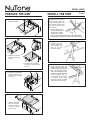
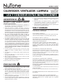
PREPARE THE UNIT
1. Remove the lamp
holder assembly.
2. Remove the heater
assembly retaining
screw.
3. Rotate heater assembly
and lift it up and out of the
housing.
4. Remove fan assembly
retaining screws. Lift
fan assembly out of the
housing.
5. Slide the 4 hanger
bars into the slots
on each end of the
housing - 2 hanger
bars per side.
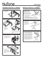
For best results, choose a
location which allows fan
to be vented outside with
the shortest possible duct
run and the fewest num-
ber of elbows.
1. Position unit between
joists and extend mount-
ing brackets. Position
brackets such that the
bottom edge of housing will be ush with nished ceiling.
Mark the top of keyhole slot on all four mounting brackets.
INSTALL THE UNIT
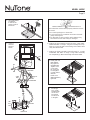
2. Remove unit tem-
porarily, and pound
nails partially into
joists at all four
marked locations.
3. Hang unit from nails and
check if unit will be ush with
nished ceiling. Pound nails
tight. For wide joist centers:
A #8 x 3/8 self-tapping screw
can be used to join extended
brackets together and cre-
ate a rigid mount. To ensure
a noise-free mount, crimp
the bracket channels tightly
around mounting brackets.

MODEL 665RP
Page 3
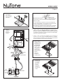
RED
BLACK
120 VAC LINE IN
HEAT
VENT
LIGHT
3 GROUND
WIRES
RED
3 GROUND WIRES
A
B
C
B
C
LIGHT
VENT
HEAT
RED
3 WHITE WIRES
BLACK
BLUE
2 WHITE
WIRES
BLACK
3 WHITE WIRES
A
4. Use a at-bladed
screwdriver
to remove the
proper electrical
knockouts.
5. Connect
electrical
wiring as
shown.
6. Replace the fan assembly removed in Step 4, under “PRE-
PARE THE UNIT” on Page 2. Plug fan assembly into recep-
tacle (C) on the the side of the wiring cover. Direct wires
away from blower inlets.
7. Replace the heater assembly removed in Steps 2, 3, under
“PREPARE THE UNIT” on Page 2. Plug heater assembly
into receptacle (A). Direct wires away from blower inlets.
If the switch has not been wired properly and wires need to
be moved:
1. Each wire opening has a release slot.
2. Push a small nail or screwdriver into release slot while
gently removing wire.
3. DO NOT pull any wire out of the switch without using
the release slot. The switch may be damaged.
WIRE OPENING
RELEASE SLOT
8. Install grille and
light reector.
Plug light into
receptacle (B).
Tighten acorn
nut securely.
Be careful not
to overtighten
nut and deform
reector.
Install a 100
Watt (maximum)
light bulb.
9. Install light
lens. Gently
squeeze tabs
on lens and
insert them
into the slots
in the grille.

MODEL 665RP
Page 4
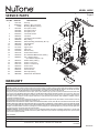
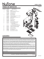
SERVICE PARTS
KEY NO. PART NO. DESCRIPTION
1 97017451 Housing
2 101183000 Damper / Duct Connector
3 44388 Mounting Bracket (4 Req.)
4 99270981 Receptacle, White
99270982 Receptacle, Black
99270489 Receptacle, Red
5 82403000 Fan Blower Wheel
6 99080592 Fan Motor
7 97017080 Fan Motor Plate Assembly
8 99260428 Nut (4 Req.)
9 89852000 Grille Assembly (includes Key No. 13)
10 98010306 Light Reector
11 97005316 Acorn Nut
12 99770112 Light Socket
13 53740000 Light Lens
14 97005058 Bolt Assembly
15 99020134 Heater Blower Wheel
16 99150576 #8 x 3/8 Sheet Metal Screw (9 Req.)
17 93260457 #10 - 32 Nut (7 Req.)
(2 included in Key No. 16)
18 99270107 Heater Hooks (5 Req.)
19 98010295 Heater Scroll Cover
20 97017070 Heater Scroll Housing
21 99080593 Heater Motor
22 98004514 Heater Element
23 99260512 Tinnerman Nut
24 99420666 Wire Clip (2 Req.)
25 98010286 Exhaust Fan Scroll Band
1
2
3
4
5
6
7
8
9
10
11
12
13
14
15
16
17
18
16
19
20
21
22
WARRANTY
99043912F
23
24
25
One Year Limited Warranty
WARRANTY OWNER: Broan-NuTone warrants to the original consumer purchaser of its products that such products will be free from defects in materials or
workmanship for a period of one (1) year from the date of original purchase. THERE ARE NO OTHER WARRANTIES, EXPRESS OR IMPLIED, INCLUDING,
BUT NOT LIMITED TO, IMPLIED WARRANTIES OF MERCHANTABILITY OR FITNESS FOR A PARTICULAR PURPOSE.
During this one year period, Broan-NuTone will, at its option, repair or replace, without charge, any product or part which is found to be defective under normal
use and service. THIS WARRANTY DOES NOT EXTEND TO FLUORESCENT LAMP STARTERS OR TUBES, FILTERS, DUCT, ROOF CAPS, WALL CAPS
AND OTHER ACCESSORIES FOR DUCTING. This warranty does not cover (a) normal maintenance and service or (b) any products or parts which have
been subject to misuse, negligence, accident, improper maintenance or repair (other than by Broan-NuTone), faulty installation or installation contrary to
recommended installation instructions.
The duration of any implied warranty is limited to the one year period as specied for the express warranty. Some states do not allow limitation on how long
an implied warranty lasts, so the above limitation may not apply to you.
BROAN-NUTONE’S OBLIGATION TO REPAIR OR REPLACE, AT BROAN-NUTONE’S OPTION, SHALL BE THE PURCHASER’S SOLE AND EXCLUSIVE
REMEDY UNDER THIS WARRANTY. BROAN-NUTONE SHALL NOT BE LIABLE FOR INCIDENTAL, CONSEQUENTIAL OR SPECIAL DAMAGES ARISING
OUT OF OR IN CONNECTION WITH PRODUCT USE OR PERFORMANCE. Some states do not allow the exclusion or limitation of incidental or consequential
damages, so the above limitation or exclusion may not apply to you. This warranty gives you specic legal rights, and you may also have other rights, which
vary from state to state. This warranty supersedes all prior warranties.
WARRANTY SERVICE: To qualify for warranty service, you must (a) notify Broan-NuTone at the address or telephone number below, (b) give the model
number and part identication and (c) describe the nature of any defect in the product or part. At the time of requesting warranty service, you must present
evidence of the original purchase date.
Date of Installation
Builder or Installer
Model No. and Product Description
IF YOU NEED ASSISTANCE OR SERVICE - CONTACT:
Broan-NuTone LLC Hartford, Wisconsin www.nutone.com 888-336-3948
Rev. 08/2007

MODELO 665RP
Página 5
ADVERTENCIA
PRECAUCIÓN
PARA REDUCIR EL RIESGO DE INCENDIOS, DESCARGAS
ELÉCTRICAS O LESIONES PERSONALES, OBSERVE LAS
SIGUIENTES PRECAUCIONES:
1. Use la unidad sólo de la manera indicada por el fabricante. Si
tiene preguntas, comuníquese con el fabricante a la dirección o al
número telefónico que se incluye en la garantía.
2. Antes de dar servicio a la unidad o de limpiarla, interrumpa el
suministro eléctrico en el panel de servicio y bloquee los medios de
desconexión del servicio para evitar que la electricidad se reanude
accidentalmente. Cuando no sea posible bloquear los medios de
desconexión del servicio, je rmemente una señal de advertencia
(tal como una etiqueta) en un lugar visible del panel de servicio.
3. Una o más personas calicadas deben realizar el trabajo de
instalación y el cableado eléctrico, de acuerdo con todos los
códigos y normas correspondientes, incluidos los códigos y normas
de construcción especícos de protección contra incendios.
4. Se necesita suciente aire para que se lleve a cabo una
combustión y escape adecuados de los gases a través del tubo
de humos (chimenea) del equipo quemador de combustible,
con el n de evitar el contratiro. Siga las directrices y las normas
de seguridad del fabricante del equipo de calentamiento, así
como las publicadas por la Asociación Nacional de Protección
contra Incendios (National Fire Protection Association, NFPA), la
Sociedad Americana de Ingenieros de Calefacción, Refrigeración
y Aire Acondicionado (American Society for Heating, Refrigeration
and Air Conditioning Engineers, ASHRAE) y los códigos de las
autoridades locales.
5. Al cortar o perforar a través de la pared o del cielo raso, tenga
cuidado de no dañar el cableado eléctrico ni otros servicios
ocultos.
6. Los ventiladores con conductos deben siempre conectarse hacia
el exterior.
7. No use esta unidad junto con ningún dispositivo de control de
velocidad de estado sólido.
8. Nunca coloque el interruptor en un lugar en donde se pueda
alcanzar desde la bañera o ducha.
9. Use la unidad sólo de la manera indicada por el fabricante. Si tiene
preguntas, comuníquese con el fabricante.
10. Esta unidad debe conectarse a tierra.
CALENTADOR / VENTILADOR / LÁMPARA
LEA Y CONSERVE ESTAS INSTRUCCIONES
1. Proporcione un circuito por separado de 20 A. Utilice un cable
eléctrico calibre 12 de un tipo conforme al código. Utilice un cable
eléctrico clasicado para por lo menos 90
O
C.
2. Este producto está diseñado solamente para instalarse en el
cielo raso. Este producto está diseñado para instalarse en cielos
rasos con pendientes de hasta 12/12. El sistema de conductos
debe apuntar hacia arriba. NO MONTE ESTE PRODUCTO EN LA
PARED.
3. Instálelo únicamente en un cielo raso, a una distancia mínima de
30,5 cm (12 pulg.) de cualquier pared.
4. Para una eciencia óptima, instale el calentador de manera que
el calor se dirija hacia el área de la bañera o de la ducha. Evite
dirigirlo hacia paredes o ventanas.
5. Sólo para usarse como medio de ventilación general. No debe
usarse para descargar materiales ni vapores peligrosos o
explosivos.
6. Para evitar daños a los cojinetes del motor y rotores ruidosos
o desequilibrados, mantenga la unidad de accionamiento al
resguardo de rociados de yeso, polvos de construcción, etc.
7. Léase la etiqueta de especicaciones que tiene el producto para
ver información y requisitos adicionales.
DESCONECTE EL SUMINISTRO ELÉCTRICO ANTES DE LIMPIAR
O DAR SERVICIO A ESTA UNIDAD.
PARA CAMBIAR LA BOMBILLA:
Quite la lente presionando ligeramente los lados y jálelo hacia abajo.
Utilice únicamente bombillas con capacidad de hasta 100 watts.
PARA LIMPIAR LA LENTE Y LA REJILLA:
Quite la lente tal como se explicó anteriormente. Quite la bombilla.
Quite la tuerca ciega que se encuentra en el centro del reector de luz
y baje el conjunto. Desenchufe la luz.
PRECAUCIÓN: La rejilla y el reector son unidades separadas.
Las piezas de plástico pueden limpiarse con una solución suave
de agua y jabón y secarse con un paño suave. NO USE PAÑOS
ABRASIVOS, ALMOHADILLAS DE LANA DE ACERO NI POLVOS
ABRASIVOS.
PARA LIMPIAR EL CONJUNTO DEL VENTILADOR:
Desenchufe el motor del ventilador. Saque los tornillos de retención.
PRECAUCIÓN: El conjunto del ventilador se vendrá hacia abajo
cuando se quiten los tornillos. Sujételo con una mano libre al tiempo
que quita los tornillos de retención.
Con una aspiradora limpie cuidadosamente el ventilador, el motor y
el interior de la cubierta. El motor está permanentemente lubricado y
nunca necesitará aceite.
PARA LIMPIAR EL CONJUNTO DEL CALENTADOR:
Desenchufe el calentador. Saque el tornillo de retención. Coloque la
punta de un destornillador entre la pared externa de la cubierta y la
abertura de descarga del calentador. Haga palanca con cuidado hasta
que la cubierta del escape deslice.
PRECAUCIÓN: La unidad se vendrá hacia abajo al soltarla. Sujete
el conjunto del calentador con una mano libre mientras hace palanca
con el destornillador.
Con una aspiradora limpie cuidadosamente el ventilador, el motor y el
interior de la cubierta.
El motor está permanentemente lubricado: nunca necesitará aceite.
NO SUMERJA NUNCA EN AGUA LAS PIEZAS METÁLICAS NI LAS
ELÉCTRICAS.
PARA VOLVER A ARMAR TODAS LAS PIEZAS ANTERIORES:
Repita todos los procedimientos explicados. No debe hacer ningún
desmontaje adicional de los conjuntos aparte de lo explicado
anteriormente.
USO Y CUIDADO
Para colocar este
producto, visite:
www.nutone.com

MODELO 665RP
Página 6
PREPARACIÓN DE LA UNIDAD
1. Saque el conjunto
del portalámpara.
2. Saque el tornillo
de retención
del conjunto del
calentador.
3. Gire el conjunto del calentador
y levántalo y sáquelo de la
cubierta.
4. Saque los tornillos de
retención del conjunto del
ventilador. Levante y saque
el conjunto del ventilador
de la cubierta.
5. Deslice las 4 barras
de suspensión en
las ranuras en cada
extremo de la cubierta:
2 barras de suspensión
por lado.
Para obtener los mejores
resultados, elija un sitio
que permita descargar el
ventilador hacia el aire libre y
donde se requiera el tramo de
conductos más corto posible
y el menor número de codos.
1. Coloque la unidad entre
las vigas y extienda los
soportes de montaje. Coloque los
soportes de manera que el borde inferior de la cubierta
quede al ras del cielo raso acabado. Marque la parte superior de la
ranura tipo bocallave en los cuatro soportes de montaje.
INSTALACIÓN DE LA UNIDAD
2. Quite temporalmente
la unidad y clave
parcialmente los
clavos en las vigas
en los cuatro lugares
marcados.
3. Cuelgue la unidad en los clavos y
compruebe si la unidad quedará al
ras con el cielo raso acabado. Clave
los clavos de manera que queden
bien ajustados. Para centros de vigas
anchas: se puede usar un tornillo
autorroscante #8 x 3/8 para unir entre
sí los soportes extendidos y crear
un montaje rígido. Para lograr un
montaje silencioso, doble los canales
del soporte ajustadamente alrededor
de los soportes de montaje.

MODELO 665RP
Página 7
ROJO
NEGRO
LÍNEA DE ENTRADA
DE 12O VCA
CALOR
VENTILADOR
LÁMPARA
3 CABLES
DE TIERRA
ROJO
3 CABLES DE TIERRA
A
B
C
B
C
LÁMPARA
VENTILADOR
CALOR
ROJO
3 CABLES BLANCOS
NEGRO
AZUL
2 CABLES
BLANCOS
NEGRO
3 CABLES BLANCOS
A
4. Con un
destornillador
plano, saque las
tapas removibles
apropiadas.
5. Haga las
conexiones
eléctricas
tal como se
muestra.
6. Vuelva a colocar el conjunto del ventilador que se desmontó en el
paso 4 de la sección “PREPARACIÓN DE LA UNIDAD” (pág. 6).
Enchufe el conjunto del ventilador en el tomacorriente (C) que está
al costado de la cubierta de conexión. Encamine los cables aleján-
dolos de las entradas del ventilador.
7. Vuelva a colocar el conjunto del calentador que se desmontó en
los pasos 2 y 3 de la sección “PREPARACIÓN DE LA UNIDAD”
(pág. 6). Enchufe el calentador en el tomacorriente (A). Encamine
los cables alejándolos de las entradas del ventilador.
Si el interruptor no está conectado apropiadamente y hay que
cambiar los cables:
1. Cada entrada para cable tiene una ranura de desenganche.
2. Meta un destornillador o clavo pequeño en la ranura de desen-
ganche al tiempo que saca el cable poco a poco.
3. NO jale ningún cable para sacarlo del interruptor, sin utilizar la
ranura de desenganche, porque podría dañar el interruptor.
ENTRADA PARA CABLE
RANURA DE
DESENGANCHE
8. Instale la rejilla y
el reector de luz.
Enchufe la luz en
el tomacorriente
(B). Apriete bien
la tuerca ciega.
Tenga cuidado de
no apretarla en
exceso porque
podría deformar el
reector.
Instale una
bombilla de
100 watts (máx.).
9. Instale la lente
de la lámpara.
Con cuidado,
presione las
lengüetas
en la lente e
insértelas en
las ranuras de
la rejilla.

MODELO 665RP
Página 8
PIEZAS DE REPUESTO
CLAVE N.º PIEZA N.º DESCRIPCIÓN
1
2
3
4
5
6
7
8
9
10
11
12
13
14
15
16
17
18
16
19
20
21
22
GARANTÍA
99043912F
23
24
25
1 97017451 Cubierta
2 101183000 Regulador de tiro / conducto
3 44388000 Soporte de montaje (se necesitan 4)
4 99270981 Tomacorriente, blanco
99270982 Tomacorriente, negro
99270489 Tomacorriente, rojo
5 82403000 Disco del ventilador
6 99080592 Motor del ventilador
7 97017080
Conjunto de la placa del motor del ventilador
8 99260428 Tuerca (se necesitan 4)
9 89852000 Conjunto de rejilla (incluyen clave n.º 13)
10 98010306 Reector de luz
11 97005316 Tuerca ciega
12 99770112 Cubo de la bombilla
13 53740000 Lente de la luz
14 97005058 Montaje de tornillos
15 99020134 Disco del soplador del calentador
16 99150576 Tornillo autorroscante #8 x 3/8
(se necesitan 9)
17 93260457 Tuerca #10 - 32 (se necesitan 7)
(2 se incluyen en la clave n.º 16)
18 99270107 Ganchos del calentador (se necesitan 5)
19 98010295 Cubierta de la espiral del calentador
20 97017070 Carcasa de la espiral del calentador
21 99080593 Motor del calentador
22 98004514 Elemento del calentador
23 99260512 Tuerca Tinnerman
24 99420666 Clip de cable (se necesitan 2)
25 98010286 Banda deslizante de ventilador
Garantia Limitada de un Año
GARANTÍA DEL PROPIETARIO: Broan-NuTone garantiza al comprador consumidor original de sus productos, por el período de un (1) año desde la fecha original
de compra, que tales productos están libres de defectos en material y mano de obra. NO HAY OTRAS GRANTÍAS, EXPRESADOS O SOBREENTENDIDAS,
INCLUYENDO, PERO NO LIMITADAS A, GRANTÍAS NO EXPRESADAS DE MERCHNTIBILIDAD O ADAPTABLES A UN PROPÓSITO EN PARTICULAR.
Durante este período de un año, Broan-NuTone reparará o reemplazará a su opción y sin costo, cualquier producto o parte que se encuentre defectuoso bajo
condiciones normales de uso y servicio. ESTA GARANTÍA NO CUBRE A LOS ARRANCADORES PARA LÁMPARAS FLUORESCENTES O A LOS TUBOS
FLUORESCENTES, FILTROS, DUCTOS, TAPAS DE TECHO, TAPAS DE PARED Y OTROS ACCESORIOS PARA CANALIZACIÓN. Esta granatía no cubre
(a) Mantenimiento y servicios normales (b) Productos o partes sujetos al mal uso, negligencia, accidente, mantenimiento inadecuado o reparaciones (port otros
ajenos a Broan-NuTone), instalación defectusoa o a una instalación contraria a las instrucciones de instalación recomendadas.
La duración de cualquier garantia no expresada está limitada a un periodo de un año según se especica en la garantia expresada. Algunos estados no permiten
limitación en cuanto a la duración de una grantia no expresada, por lo que la limitación arriba indicada puede que no se apliqué a Ud.
LA OBLIGACIÓN DE BROAN-NUTONE DE REPARAR O REEMPLAZAR A SU OPCIÓN, SERÁ EL ÚNICO Y EXCLUSIVO RECURSO QUE TENDRÁ EL
COMPRADOR BAJO ESTA GARANTÍA. BROAN-NUTONE NO SERÁ RESPONSABLE POR DAÑOS INCIDENTALES, CONSECUENTES O ESPECIALES
QUE RESULTEN A CONSECUENCIA O SEAN INDEPENDIENTE DEL USO O DESEMPEÑO DEL PRODUCTO. Algunos estados no permiten la exclusión o
limitación de daños incidentals o consecuentes, de modo que la limitación o exclusión arriba indicada pueda que no se aplique a Ud. Esta garantia le proporciona
derechos legales especicos, y Ud.puede tener otros derechos, los cuales varían de estado a estado. Esta garantias reemplaza a todas las garantías anteriores..
SERVICO DE GARANTÍA: Para tener derecho al servicio de garantía, Ud. debe (a) Noticar a Broan-NuTone a la dirección o el número de teléfono abajo,
(b) indicar el número de modelo y la identifación de la party y (c) describir la naturaleza de cualquier defecto en la producto o parte. Al momento de solicitor el
servicio por la garantía, Ud. debe presentar la evidencia de la fecha original de compra.
Fecha de la instalación
Constructor o instalador
Número de modelo y descripción del producto
SI NECESITA ASISTENCIA O SERIVIVIO - CONTACTO:
Broan-NuTone LLC Hartford, Wisconsin www.nutone.com 888-336-3948
Rev. 08/2007
-
 1
1
-
 2
2
-
 3
3
-
 4
4
-
 5
5
-
 6
6
-
 7
7
-
 8
8


NuTone 665RP Manual de usuario
- Tipo
- Manual de usuario
- Este manual también es adecuado para
en otros idiomas
- English: NuTone 665RP User manual