Johnson Controls VP140LCB Installation Instructions Manual
- Tipo
- Installation Instructions Manual

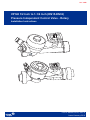
VP140 1/2 Inch to 1-1/4 Inch (DN15-DN32)
Pressure Independent Control Valve - Rotary
Installation Instructions
P/N 14-88360-03419, Rev. B
Issued January 2019
Istr. 240B

1
P/N 14-88360-03419, Rev. B
Warnings and considerations
Warning: Risk of electric shock
Disconnect the power supply before making electrical connections. Contact with components carrying hazardous voltage
can cause electric shock and may result in severe personal injury or death.
Avertissement : Risque de choc électrique
Coupez l’alimentation électrique avant d’effectuer tout branchement électrique. Le contact avec un composant chargé
électriquement peut provoquer un choc électrique pouvant causer des blessures corporelles graves ou mortelles.
Advertencia: Riesgo de descarga eléctrica
Desconecte el suministro de energía antes de hacer conexiones eléctricas. El contacto con componentes conductores de
tensión peligrosa puede provocar una descarga eléctrica y puede dar lugar a lesiones personales graves o la muerte.
Caution
Johnson Controls, Inc. does not accept any liability for improper or wrong use of this product. Proper water treatment is rec-
ommended; refer to the VDI 2035 Guideline. Furthermore, maximum iron oxide in the water passing through control valve
(PICV) should not exceed 25 mg/Kg (25 ppm). To ensure the main pipework is cleaned appropriately, flushing by-passes
should be used without flushing through the pressure regulator of the Pressure Independent Control Valve.
Attention
Johnson Controls, Inc. ne peut être tenu responsable de l’utilisation inadéquate de ce produit. Le traitement adéquat de
l’eau est recommandé; reportez-vous à la directive VDI 2035. De plus, la teneur en oxyde de fer de l’eau circulant dans
la vanne de régulation indépendante de la pression (PICV) ne devrait pas dépasser 25 mg/kg (25 ppm). Pour s’assurer
que la canalisation principale est bien nettoyée, il est recommandé d’utiliser un dispositif de dérivation afin de rincer la ca-
nalisation sans rincer le régulateur de pression de la vanne de régulation indépendante de la pression.
Precaución
Johnson Controls, Inc. no asume ninguna responsabilidad por el uso inapropiado o incorrecto de este producto.
Se recomienda el tratamiento correcto del agua. Consulte la Guía VDI 2035. Además, el óxido de hierro máximo en el
agua que pasa a través de la válvula de control de presión independiente (Pressure Independent Control Valve, PICV)
no debe superar los 25 mg/kg (25 ppm). Para asegurar la limpieza correcta de la tubería principal, se deben usar by-passes
de purga sin purgar el regulador de presión de la válvula de control de presión independiente.

2
P/N 14-88360-03419, Rev. B
Instrucciones de cableado para el técnico
• Todo el cableado cumple con los códigos locales y debe estar a cargo de personal autorizado únicamente.
• Mantenga separado el cableado de alta y baja tensión.
• Cuando use cables de trenzado múltiple, aplique una virola en el extremo del cable.
• Asegúrese de que el suministro de energía de la línea coincida con el suministro de energía que se especifica
en el dispositivo.
• Revise todas las conexiones del cableado antes de aplicar energía al sistema.
Los cables con cortocircuito o mal conectados pueden provocar daños permanentes en el equipo.
Mounting considerations for the technician
All Spring and Non-Spring Actuators ship from the factory in the fully up position. Before mounting the actuator, you must
note the following:
• Ensure that the actuator is free from thermal insulating material.
• Allow a minimum clearance of 3 1/2 inches (89mm) above the actuator body.
• If the actuator was powered before mounting on the valve, you must return the actuator to its original open position
before proceeding.
• The actuator must be independently mounted in a vertical or horizontal position.
Instructions d’installation pour le technicien
Tous les actionneurs à ressort ou sans ressort sont livrés en position complètement relevée. Avant d’installer l’actionneur,
veuillez vous assurer :
• que le matériau d’isolation thermique a été retiré de l’actionneur;
• qu’il existe un dégagement de 89 mm (3 1/2 po) au-dessus du corps de l’actionneur;
• que l’actionneur a été remis à sa position d’origine s’il avait été mis sous tension avant d’être installé sur la vanne; et
• que l’actionneur est installé à la position verticale ou horizontale de façon indépendante.
Consideraciones de montaje para el técnico
Todos los accionadores con y sin resorte se entregan de fábrica en la posición totalmente hacia arriba. Antes de montar el
accionador, debe tener en cuenta lo siguiente:
• Asegúrese de que el accionador esté libre de material aislante térmico.
• Deje una distancia mínima de 3 1/2 pulg (89 mm) por encima del cuerpo del accionador.
•
Si el accionador se encendió antes de montar la válvula, debe volver a ponerlo en su posición abierta original antes
de continuar.
•
El accionador se debe montar de forma independiente en posición vertical u horizontal.
Wiring instructions for the technician
• All wiring conforms to local codes and must be carried out by authorized personnel only.
• Keep high and low voltage wiring separated.
• When using multi-stranded wire apply a cable ferrule to the cable end.
• Make sure that the line power supply is in accordance with the power supply specified on the device.
• Check all wiring connections before applying power to the system.
• Short-circuited or improperly connected wires may result in permanent damage to the equipment.
Instructions de câblage pour le technicien
• Tous les câblages doivent se conformer aux codes locaux et être effectués par un technicien autorisé.
• Le câblage haute tension et le câblage basse tension doivent être séparés.
• Lorsqu’un câble à faisceaux torsadés est utilisé, installez une bague à l’extrémité du câble.
• Assurez-vous que la source d’alimentation électrique correspond à l’alimentation spécifiée sur l’appareil.
• Vérifiez tous les raccordements avant de mettre l’appareil sous tension.
• Tout court-circuit ou câble incorrectement branché pourrait endommager l’équipement de façon permanente.

3
P/N 14-88360-03419, Rev. B
For additional installation information and technical specifications, refer to the appropriate document:
• VA9104-xGA-2S Series Electric Non-Spring Return Valve Actuators Installation Instructions Part No. 14-1336-15
• VA9203-AGx-2Z Series On/Off and Floating Point Electric Spring Return Valve Actuators Installation Instructions Part
No. 14-1380-8
• VA9203-GGx-xx Series Proportional Electric Spring Return Valve Actuators Installation Instructions Part No. 14-1380-
24
Maintenance and cleaning
During valve cleaning operations, use a damp cloth. Do not use any detergent or chemical product that may seriously dam-
age or compromise the proper functioning and reliability of the valve.
Entretien et nettoyage
Utilisez un linge humide pour nettoyer la vanne. N’utilisez aucun détergent ou produit chimique pouvant endommager la
vanne ou nuire à son bon fonctionnement.
Mantenimiento y limpieza
Durante las operaciones de limpieza de las válvulas, utilice un paño húmedo. No use ningún detergente ni producto químico
que pueda dañar gravemente la válvula o perjudicar el funcionamiento adecuado y la fiabilidad del componente.
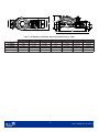
Dimensions
B
D
E
C
A
Table 1: VP140 Lxx and VP140 Mxx dimensions in. (mm)
Valve Size A B C D E
VP140LCA 1/2” DN15 2.4 (62) 2.9 (73) 0.8 (20) 6 (142) 6.2 (158)
VP140LCB 1/2” DN15 2.4 (62) 2.9 (73) 0.8 (20) 6 (142) 6.2 (158)
VP140LAJ 1/2” DN15 2.4 (62) 2.9 (73) 0.8 (20) 6 (142) 6.2 (158)
VP140MAG 3/4” DN20 2.4 (62) 2.9 (73) 0.8 (20) 6 (142) 6.2 (158)
3/4” DN20 2.4 (62) 2.9 (73) 0.8 (20) 6 (142) 6.2 (158)

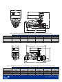
B
C
D
F
E E
A
4
P/N 14-88360-03419, Rev. B
Table 2: VP140 Mxx, VP140 Nxx, VP140 Pxx dimensions in. (mm)
Valve Size A B C D E F
VP140MAU 3/4” DN20 3.2 (80) 3.9 (98) 1 (27) 7.7 (195) 0.8 (20) 9.3 (235)
VP140NAU 1” DN25 3.2 (80) 3.9 (98) 1 (27) 7.7 (195) 0.9 (25) 9.6 (244)
VP140NAW 1” DN25 3.2 (80) 3.9 (98) 1 (27) 7.7 (195) 0.9 (25) 9.6 (244)
VP140PAY 1-1/4” DN32 3.2 (80) 3.9 (98) 1 (27) 7.7 (195) 1.5 (37) 10.59 (269)
VP140PCD 1-1/4” DN32 3.2 (80) 3.9 (98) 1 (27) 7.7 (195) 1.5 (37) 10.59 (269)

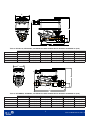
A
C
E
B
D
E
D
C
A
B
5
P/N 14-88360-03419, Rev. B
Table 3: VP140 Lxx and VP140 Mxx with VA-9104 Series Actuator assembled in. (mm)
Table 4: VP140 Mxx, VP140 Nxx and VP140 Pxx with VA-9104 Series Actuator assembled in. (mm)
Valve Size A B C D E
VP140LCA+9A4xxx 1/2”” DN15 5.2 (133) 1 (20) 5.6 (142) 6.2 (158) 2.9 (75)
VP140LCB+9A4xxx 1/2” DN15 5.2 (133) 1 (20) 5.6 (142) 6.2 (158) 2.9 (75)
VP140LAJ+9A4xxx 1/2” DN15 5.2 (133) 1 (20) 5.6 (142) 6.2 (158) 2.9 (75)
VP140MAG+9A4xxx 3/4” DN20 5.2 (133) 1 (20) 5.6 (142) 6.2 (158) 2.9 (75)
VP140MCC+9A4xxx 3/4” DN20 5.2 (133) 1 (20) 5.6 (142) 6.2 (158) 2.9 (75)
Valve Size A B C D E
VP140MAU+9A4xxx 3/4” DN20 6 (151) 1.2 (30) 8.5 (217) 9.4 (238) 3.2 (80)
VP140NAU+9A4xxx 1” DN25 6 (151) 1.2 (30) 8.5 (217) 9.4 (238) 3.2 (80)
VP140NAW+9A4xxx 1” DN25 6 (151) 1.2 (30) 8.7 (220) 9.6 (245) 3.2 (80)
VP140PAY+9A4xxx 1-1/4” DN32 6 (151) 1.2 (30) 9.2 (233) 10.7 (271) 3.2 (80)
VP140PCD+9A4xxx 1-1/4” DN32 6 (151) 1.2 (30) 9.2 (233) 10.7 (271) 3.2 (80)

A
C
E
B
D
C
A
B
D
E
6
P/N 14-88360-03419, Rev. B
Table 5: VP140 Lxx, VP140 Nxx, and VP140 Pxx with VA-9203 Series Actuator assembled in. (mm)
Table 6: VP140MAU, VP140Nxx, and VP140 Pxx with VA-9203 Series Actuator assembled in. (mm)
Valve Size A B C D E
VP140LCA+923xxx 1/2” DN20 6 (149) 0.8 (20) 5.6 (142) 8.7 (220) 3.2 (82)
VP140LCB+923xxx 1/2” DN25 6 (149) 0.8 (20) 5.6 (142) 8.7 (220) 3.2 (82)
VP140LAJ+923xxx 1/2” DN25 6 (149) 0.8 (20) 5.6 (142) 8.7 (220) 3.2 (82)
VP140MAG+923xxx 3/4” DN32 6 (149) 0.8 (20) 5.6 (142) 8.7 (220) 3.2 (82)
VP140MCC+923xxx 3/4” DN32 6 (149) 0.8 (20) 5.6 (142) 8.7 (220) 3.2 (82)
Valve Size A B C D E
VP140MAU+923xxx 3/4” DN20 6.6 (167) 1.2 (30) 9.4 (238) 9.2 (234) 3.2 (82)
VP140NAU+923xxx 1” DN25 6.6 (167) 1.2 (30) 9.4 (238) 9.2 (234) 3.2 (82)
VP140NAW+923xxx 1” DN25 6.6 (167) 1.2 (30) 9.6 (245) 9.8 (249) 3.2 (82)
VP140PAY+923xxx 1-1/4” DN32 6.6 (167) 1.2 (30) 10.7 (271) 10 (256) 3.2 (82)
VP140PCD+923xxx 1-1/4” DN32 6.6 (167) 1.2 (30) 10.7 (271) 10 (256) 3.2 (82)

7
P/N 14-88360-03419, Rev. B
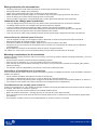
Flow direction | Sens du débit | Dirección del flujo
The following diagram illustrates the flow direction. Use this diagram as a guide on how to attach the actuator. If flow reversal
is possible, mount a a non-return valve. See Table 10 for the minimum differential pressure required.
Le diagramme ci-dessous illustre le sens du débit. Reportez-vous à ce diagramme pour l’installation de l’actionneur. S’il est
possible de renverser le débit, installez un clapet antiretour. Consultez le Table 6 pour connaître la pression différentielle
minimale requise.
En el siguiente diagrama, se muestra la dirección del flujo. Use este diagrama como una guía sobre cómo conectar el ac-
cionador. Si el retorno del flujo es posible, instale una válvula de no retorno. Consulte la Tabla 6 para conocer la presión
diferencial mínima requerida.
CAUTION: Mounting in the wrong direction may damage the system and the valve.
ATTENTION : Installer la vanne dans le mauvais sens pourrait endommager le système et la vanne.
PRECAUCIÓN: El montaje en la dirección incorrecta puede dañar el sistema y la válvula.

8
P/N 14-88360-03419, Rev. B
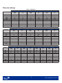
Flow rate settings
Table 7: VP140Lxx
Table 8: VP140Mxx
Table 9: VP140Nxx and Pxx
VP140 LCA VP140 LCB VP140 LAJ
Pre-Setting Flow
GPM
Flow
l/h
Flow
GPM
Flow
l/h
Flow
GPM
Flow
l/h
100% 1.6 360 3.0 700 4.4 1000
90% 0.9 210 2.5 563 4.2 960
80% 0.5 114 1.5 341 3.7 845
70% 0.3 75 1.0 207 3.2 737
60% 0.2 53 0.7 153 2.5 570
50% 0.16 36 0.4 98 1.7 380
40% 0.07 15 0.3 74 1.0 232
30% 0.02 4 0.2 39 0.6 132
20% -- -- -- -- 0.1 23
10% -- -- -- -- -- --
VP14MAG VP140MCC VP140MAU
Pre-Setting Flow
GPM
Flow
l/h
Flow
GPM
Flow
l/h
Flow
GPM
Flow
l/h
100% 3.4 780 5.0 1,150 9.7 2,200
90% 2.8 626 4.9 1,122 7.1 1,615
80% 1.7 286 4.5 1,032 4.5 1,015
70% 1.0 215 3.5 805 2.9 647
60% 0.7 153 2.5 561 2.2 508
50% 0.6 129 1.4 323 1.6 372
40% 0.4 93 0.6 141 0.9 213
30% 0.2 53 0.04 9 0.5 121
20% -- -- -- -- 0.2 44
10% -- -- -- -- -- --
VP140NAU VP140NAW VP140PAY VP140PCD
Pre-Setting Flow
GPM
Flow
l/h
Flow
GPM
Flow
l/h
Flow
GPM
Flow
l/h
Flow
GPM
Flow
l/h
100% 9.7 2,200 11.9 2,700 13.2 3,000 17.6 4,000
90% 7.1 1,615 8.7 1,978 10.5 2,383 15.9 3.621
80% 4.5 1,015 5.4 1,237 7.3 1,654 14.2 3,220
70% 2.9 647 3.5 795 4.5 1,017 11.4 2,594
60% 2.2 508 2.7 623 2.8 642 8.2 1,853
50% 1.6 372 2.0 456 2.0 445 4.5 1,088
40% 0.9 213 1.1 257 1.3 288 2.2 510
30% 0.5 121 0.6 144 0.7 162 0.7 147
20% 0.2 44 0.2 54 0.3 76 0.2 47
10% -- -- -- -- -- -- -- --

9
P/N 14-88360-03419, Rev. B
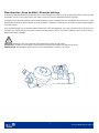
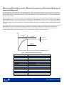
Measuring differential pressure | Mesure de la pression différentielle |Medición de
la presión diferencial
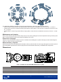
To ensure that the valve is working in the operating range, measure the differential gauge across the valve. The valve is in
the operating range if the value at P1-P2 (ΔP) is higher than the start up value. If the ΔP measured value is lower than the
start up value, then the valve works as a fixed orifice valve. Use the following table as reference for minimum differential
pressure requirements.
Pour vous assurer que la vanne fonctionne dans la plage de fonctionnement, relevez la pression indiquée sur le manomètre
différentiel de la vanne. La vanne fonctionne dans la plage de fonctionnement si la valeur de P1-P2 (ΔP) est plus élevée
que la valeur de mise en service. Si la mesure de ΔP est inférieure à la valeur de mise en service, cela signifie que la vanne
fonctionne comme une vanne à orifice fixe. Consultez le tableau suivant pour connaître la pression différentielle minimale
requise.
Para asegurarse de que la válvula funcione en el rango de funcionamiento, mida el ancho diferencial a través de la válvula.
Si el valor en P1-P2 (ΔP) es superior al valor de arranque, la válvula se encuentra en el rango de funcionamiento.
Si el valor ΔP medido es inferior al valor de arranque, entonces la válvula funciona como una válvula de orificio fijo.
Use la siguiente tabla como referencia para conocer los requisitos de presión diferencial mínima.
Q≠CONST
Q=CONST
START-UP
PRESSURE
HYSTERESIS
Q
P1 - P2
Table 10: Minimum differential pressure
Product codes
Start-up ΔP
VP140Lxx
VP140LCA 2.90 psi, 20 kPa
VP140LCB 2.90 psi, 20 kPa
VP140LAJ 2.90 psi, 20 kPa
VP140 Mxx
VP140MAG 3.63 psi, 25 kPa
VP140MCC 3.63 psi, 25 kPa
VP140MAU 4.35 psi, 30 kPa
VP140Nxx
VP140NAU 4.35 psi, 30 kPa
VP140NAW 4.35 psi, 30 kPa
VP140Pxx
VP140PAY 4.35 psi, 30 kPa
VP140PCD 4.35 psi, 30 kPa

10
P/N 14-88360-03419, Rev. B
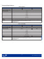
Technical Specifications
Table 9: VP140Lxx
Table 10: VP140Mxx
VP140LCA VP140LCB VP140LAJ
Flow rate max.
1.6 GPM, 360 l/h 3.0 GPM, 600 l/h 4.4 GPM, 1,000 l/h
Service Water or water-glycol mixture (up to 50% glycol), quality to VDI 2035
Accuracy up to 15 PSID = 100 kPa
± 5%
Minimum ΔP for start-up
2.9 psi
20 kPa
Maximum ΔP
58 psi
400 kPa
Maximum working pressure
360 psi
2,482 kPa
Close off pressure
200 psi
1,379 kPa
Temperature
14 to 248 °F
-10 to 120 °C
Connection
½” FNPT
Leakage
Class IV IEC 60534-4
Compliance
Johnson Controls declares that these products are in compliance with the essential requirements and other relevant provisions
of the PED (Pressure Equipment Directive) 2014/68/UE (Paragraph 4, comma 3).
CE Marking is not applicable.
ROHS (95/2002/CE)
VP140MAG VP140MCC VP140MAU
Flow rate max. 3.4 GPM, 780 l/h 5.0 GPM, 1,150 l/h 9.7 GPM, 2,200 l/h
Service Water or water-glycol mixture (up to 50% glycol), quality to VDI 2035
Accuracy up to 15 PSID = 100 kPa
± 5%
Minimum ΔP for start-up
3.6 psi
25 kPa
4.4 psi
30 kPa
Maximum ΔP
58 psi
400 kPa
Maximum working pressure
360 psi
2,482 kPa
Close off pressure
200 psi
1,379 kPa
Temperature
14 to 248 °F
-10 to 120 °C
Connections ¾” FNPT ¾” FNPT Union
Leakage Class IV IEC 60534-4
Compliance
Johnson Controls declares that these products are in compliance with the essential requirements and other relevant provisions
of the PED (Pressure Equipment Directive) 2014/68/UE (Paragraph 4, comma 3).
CE Marking is not applicable.
ROHS (95/2002/CE)

Building Technologies & Solutions
507 E. Michigan Street, Milwaukee, WI 53202
www.johnsoncontrols.com
Metasys® and Johnson Controls® are registered trademarks of Johnson Controls.
All other marks herein are the marks of their respective owners. © 2019 Johnson Controls.
11
P/N 14-88360-03419, Rev. B
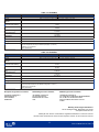
Table 11: VP140Nxx
Table 12: VP140Pxx
VP140NAU VP140NAW
Flow rate max. 9.7 GPM, 2,200 l/h 11.9 GPM, 2,700 l/h
Service Water or water-glycol mixture (up to 50% glycol), quality to VDI 2035
Accuracy up to 15 PSID =
100 kPa
± 5%
Minimum ΔP for start-up
4.4 psi
30 kPa
Maximum ΔP
58 psi
400 kPa
Maximum working pressure
360 psi
2,482 kPa
Close off pressure
200 psi
1,379 kPa
Temperature
14 to 248 °F
-10 to 120 °C
Connections 1" FNPT Union
Leakage Class IV IEC 60534-4
Compliance
Johnson Controls declares that these products are in compliance with the essential requirements and other relevant provisions of the PED
(Pressure Equipment Directive) 2014/68/UE (Paragraph 4, comma 3).
CE Marking is not applicable.
ROHS (95/2002/CE)
VP140PAY VP140PCD
Flow rate max. 13.2 GPM, 3,000 l/h 17.6 GPM, 4,000 l/h
Service Water or water-glycol mixture (up to 50% glycol), quality to VDI 2035
Accuracy up to 15 PSID =
100 kPa
± 5%
Minimum ΔP for start-up
4.4 psi
30 kPa
Maximum ΔP
58 psi
400 kPa
Maximum working pres-
sure
360 psi
2,482 kPa
Close off pressure
200 psi
1,379 kPa
Temperature
14 to 248 °F
-10 to 120 °C
Connections 1 ¼” FNPT Union
Leakage Class IV IEC 60534-4
Compliance
Johnson Controls declares that these products are in compliance with the essential requirements and other relevant provisions of the PED
(Pressure Equipment Directive) 2014/68/UE (Paragraph 4, comma 3).
CE Marking is not applicable.
ROHS (95/2002/CE)
European Single Point of Contact: NA/SA Single Point of Contact: APAC Single Point of Contact:
JOHNSON CONTROLS
WESTENDHOF 3
45143 ESSEN
GERMANY
JOHNSON CONTROLS
507 E MICHIGAN ST
MILWAUKEE WI 53202
USA
JOHNSON CONTROLS
C/O CONTROLS PRODUCT MANAGEMENT
NO. 22 BLOCK D NEW DISTRICT
WUXI JIANGSU PROVINCE 214142
CHINA
Transcripción de documentos
Istr. 240B VP140 1/2 Inch to 1-1/4 Inch (DN15-DN32) Pressure Independent Control Valve - Rotary Installation Instructions P/N 14-88360-03419, Rev. B Issued January 2019 Warnings and considerations Warning: Risk of electric shock Disconnect the power supply before making electrical connections. Contact with components carrying hazardous voltage can cause electric shock and may result in severe personal injury or death. Avertissement : Risque de choc électrique Coupez l’alimentation électrique avant d’effectuer tout branchement électrique. Le contact avec un composant chargé électriquement peut provoquer un choc électrique pouvant causer des blessures corporelles graves ou mortelles. Advertencia: Riesgo de descarga eléctrica Desconecte el suministro de energía antes de hacer conexiones eléctricas. El contacto con componentes conductores de tensión peligrosa puede provocar una descarga eléctrica y puede dar lugar a lesiones personales graves o la muerte. Caution Johnson Controls, Inc. does not accept any liability for improper or wrong use of this product. Proper water treatment is recommended; refer to the VDI 2035 Guideline. Furthermore, maximum iron oxide in the water passing through control valve (PICV) should not exceed 25 mg/Kg (25 ppm). To ensure the main pipework is cleaned appropriately, flushing by-passes should be used without flushing through the pressure regulator of the Pressure Independent Control Valve. Attention Johnson Controls, Inc. ne peut être tenu responsable de l’utilisation inadéquate de ce produit. Le traitement adéquat de l’eau est recommandé; reportez-vous à la directive VDI 2035. De plus, la teneur en oxyde de fer de l’eau circulant dans la vanne de régulation indépendante de la pression (PICV) ne devrait pas dépasser 25 mg/kg (25 ppm). Pour s’assurer que la canalisation principale est bien nettoyée, il est recommandé d’utiliser un dispositif de dérivation afin de rincer la canalisation sans rincer le régulateur de pression de la vanne de régulation indépendante de la pression. Precaución Johnson Controls, Inc. no asume ninguna responsabilidad por el uso inapropiado o incorrecto de este producto. Se recomienda el tratamiento correcto del agua. Consulte la Guía VDI 2035. Además, el óxido de hierro máximo en el agua que pasa a través de la válvula de control de presión independiente (Pressure Independent Control Valve, PICV) no debe superar los 25 mg/kg (25 ppm). Para asegurar la limpieza correcta de la tubería principal, se deben usar by-passes de purga sin purgar el regulador de presión de la válvula de control de presión independiente. 1 P/N 14-88360-03419, Rev. B Wiring instructions for the technician • • • • • • All wiring conforms to local codes and must be carried out by authorized personnel only. Keep high and low voltage wiring separated. When using multi-stranded wire apply a cable ferrule to the cable end. Make sure that the line power supply is in accordance with the power supply specified on the device. Check all wiring connections before applying power to the system. Short-circuited or improperly connected wires may result in permanent damage to the equipment. Instructions de câblage pour le technicien • • • • • • Tous les câblages doivent se conformer aux codes locaux et être effectués par un technicien autorisé. Le câblage haute tension et le câblage basse tension doivent être séparés. Lorsqu’un câble à faisceaux torsadés est utilisé, installez une bague à l’extrémité du câble. Assurez-vous que la source d’alimentation électrique correspond à l’alimentation spécifiée sur l’appareil. Vérifiez tous les raccordements avant de mettre l’appareil sous tension. Tout court-circuit ou câble incorrectement branché pourrait endommager l’équipement de façon permanente. Instrucciones de cableado para el técnico • • • • Todo el cableado cumple con los códigos locales y debe estar a cargo de personal autorizado únicamente. Mantenga separado el cableado de alta y baja tensión. Cuando use cables de trenzado múltiple, aplique una virola en el extremo del cable. Asegúrese de que el suministro de energía de la línea coincida con el suministro de energía que se especifica en el dispositivo. • Revise todas las conexiones del cableado antes de aplicar energía al sistema. Los cables con cortocircuito o mal conectados pueden provocar daños permanentes en el equipo. Mounting considerations for the technician All Spring and Non-Spring Actuators ship from the factory in the fully up position. Before mounting the actuator, you must note the following: • Ensure that the actuator is free from thermal insulating material. • Allow a minimum clearance of 3 1/2 inches (89mm) above the actuator body. • If the actuator was powered before mounting on the valve, you must return the actuator to its original open position before proceeding. • The actuator must be independently mounted in a vertical or horizontal position. Instructions d’installation pour le technicien Tous les actionneurs à ressort ou sans ressort sont livrés en position complètement relevée. Avant d’installer l’actionneur, veuillez vous assurer : • que le matériau d’isolation thermique a été retiré de l’actionneur; • qu’il existe un dégagement de 89 mm (3 1/2 po) au-dessus du corps de l’actionneur; • que l’actionneur a été remis à sa position d’origine s’il avait été mis sous tension avant d’être installé sur la vanne; et • que l’actionneur est installé à la position verticale ou horizontale de façon indépendante. Consideraciones de montaje para el técnico Todos los accionadores con y sin resorte se entregan de fábrica en la posición totalmente hacia arriba. Antes de montar el accionador, debe tener en cuenta lo siguiente: • Asegúrese de que el accionador esté libre de material aislante térmico. • Deje una distancia mínima de 3 1/2 pulg (89 mm) por encima del cuerpo del accionador. • Si el accionador se encendió antes de montar la válvula, debe volver a ponerlo en su posición abierta original antes de continuar. • El accionador se debe montar de forma independiente en posición vertical u horizontal. 2 P/N 14-88360-03419, Rev. B For additional installation information and technical specifications, refer to the appropriate document: • VA9104-xGA-2S Series Electric Non-Spring Return Valve Actuators Installation Instructions Part No. 14-1336-15 • VA9203-AGx-2Z Series On/Off and Floating Point Electric Spring Return Valve Actuators Installation Instructions Part No. 14-1380-8 • VA9203-GGx-xx Series Proportional Electric Spring Return Valve Actuators Installation Instructions Part No. 14-138024 Maintenance and cleaning During valve cleaning operations, use a damp cloth. Do not use any detergent or chemical product that may seriously damage or compromise the proper functioning and reliability of the valve. Entretien et nettoyage Utilisez un linge humide pour nettoyer la vanne. N’utilisez aucun détergent ou produit chimique pouvant endommager la vanne ou nuire à son bon fonctionnement. Mantenimiento y limpieza Durante las operaciones de limpieza de las válvulas, utilice un paño húmedo. No use ningún detergente ni producto químico que pueda dañar gravemente la válvula o perjudicar el funcionamiento adecuado y la fiabilidad del componente. Dimensions B A C E D Table 1: VP140 Lxx and VP140 Mxx dimensions in. (mm) Valve Size A B C D E VP140LCA 1/2” DN15 2.4 (62) 2.9 (73) 0.8 (20) 6 (142) 6.2 (158) VP140LCB 1/2” DN15 2.4 (62) 2.9 (73) 0.8 (20) 6 (142) 6.2 (158) VP140LAJ 1/2” DN15 2.4 (62) 2.9 (73) 0.8 (20) 6 (142) 6.2 (158) VP140MAG 3/4” DN20 2.4 (62) 2.9 (73) 0.8 (20) 6 (142) 6.2 (158) 3/4” DN20 2.4 (62) 2.9 (73) 0.8 (20) 6 (142) 6.2 (158) 3 P/N 14-88360-03419, Rev. B B A C E E D F Table 2: VP140 Mxx, VP140 Nxx, VP140 Pxx dimensions in. (mm) Valve Size A B C D E F VP140MAU 3/4” DN20 3.2 (80) 3.9 (98) 1 (27) 7.7 (195) 0.8 (20) 9.3 (235) VP140NAU 1” DN25 3.2 (80) 3.9 (98) 1 (27) 7.7 (195) 0.9 (25) 9.6 (244) VP140NAW 1” DN25 3.2 (80) 3.9 (98) 1 (27) 7.7 (195) 0.9 (25) 9.6 (244) VP140PAY 1-1/4” DN32 3.2 (80) 3.9 (98) 1 (27) 7.7 (195) 1.5 (37) 10.59 (269) VP140PCD 1-1/4” DN32 3.2 (80) 3.9 (98) 1 (27) 7.7 (195) 1.5 (37) 10.59 (269) 4 P/N 14-88360-03419, Rev. B E A B C D Table 3: VP140 Lxx and VP140 Mxx with VA-9104 Series Actuator assembled in. (mm) Valve Size A B C D E VP140LCA+9A4xxx 1/2”” DN15 5.2 (133) 1 (20) 5.6 (142) 6.2 (158) 2.9 (75) VP140LCB+9A4xxx 1/2” DN15 5.2 (133) 1 (20) 5.6 (142) 6.2 (158) 2.9 (75) VP140LAJ+9A4xxx 1/2” DN15 5.2 (133) 1 (20) 5.6 (142) 6.2 (158) 2.9 (75) VP140MAG+9A4xxx 3/4” DN20 5.2 (133) 1 (20) 5.6 (142) 6.2 (158) 2.9 (75) VP140MCC+9A4xxx 3/4” DN20 5.2 (133) 1 (20) 5.6 (142) 6.2 (158) 2.9 (75) C E A B D Table 4: VP140 Mxx, VP140 Nxx and VP140 Pxx with VA-9104 Series Actuator assembled in. (mm) Valve Size A B C D E VP140MAU+9A4xxx 3/4” DN20 6 (151) 1.2 (30) 8.5 (217) 9.4 (238) 3.2 (80) VP140NAU+9A4xxx 1” DN25 6 (151) 1.2 (30) 8.5 (217) 9.4 (238) 3.2 (80) VP140NAW+9A4xxx 1” DN25 6 (151) 1.2 (30) 8.7 (220) 9.6 (245) 3.2 (80) VP140PAY+9A4xxx 1-1/4” DN32 6 (151) 1.2 (30) 9.2 (233) 10.7 (271) 3.2 (80) VP140PCD+9A4xxx 1-1/4” DN32 6 (151) 1.2 (30) 9.2 (233) 10.7 (271) 3.2 (80) 5 P/N 14-88360-03419, Rev. B E A B C D Table 5: VP140 Lxx, VP140 Nxx, and VP140 Pxx with VA-9203 Series Actuator assembled in. (mm) Valve Size A B C D E VP140LCA+923xxx 1/2” DN20 6 (149) 0.8 (20) 5.6 (142) 8.7 (220) 3.2 (82) VP140LCB+923xxx 1/2” DN25 6 (149) 0.8 (20) 5.6 (142) 8.7 (220) 3.2 (82) VP140LAJ+923xxx 1/2” DN25 6 (149) 0.8 (20) 5.6 (142) 8.7 (220) 3.2 (82) VP140MAG+923xxx 3/4” DN32 6 (149) 0.8 (20) 5.6 (142) 8.7 (220) 3.2 (82) VP140MCC+923xxx 3/4” DN32 6 (149) 0.8 (20) 5.6 (142) 8.7 (220) 3.2 (82) E A B C D Table 6: VP140MAU, VP140Nxx, and VP140 Pxx with VA-9203 Series Actuator assembled in. (mm) Valve Size A B C D E VP140MAU+923xxx 3/4” DN20 6.6 (167) 1.2 (30) 9.4 (238) 9.2 (234) 3.2 (82) VP140NAU+923xxx 1” DN25 6.6 (167) 1.2 (30) 9.4 (238) 9.2 (234) 3.2 (82) VP140NAW+923xxx 1” DN25 6.6 (167) 1.2 (30) 9.6 (245) 9.8 (249) 3.2 (82) VP140PAY+923xxx 1-1/4” DN32 6.6 (167) 1.2 (30) 10.7 (271) 10 (256) 3.2 (82) VP140PCD+923xxx 1-1/4” DN32 6.6 (167) 1.2 (30) 10.7 (271) 10 (256) 3.2 (82) 6 P/N 14-88360-03419, Rev. B Flow direction | Sens du débit | Dirección del flujo The following diagram illustrates the flow direction. Use this diagram as a guide on how to attach the actuator. If flow reversal is possible, mount a a non-return valve. See Table 10 for the minimum differential pressure required. Le diagramme ci-dessous illustre le sens du débit. Reportez-vous à ce diagramme pour l’installation de l’actionneur. S’il est possible de renverser le débit, installez un clapet antiretour. Consultez le Table 6 pour connaître la pression différentielle minimale requise. En el siguiente diagrama, se muestra la dirección del flujo. Use este diagrama como una guía sobre cómo conectar el accionador. Si el retorno del flujo es posible, instale una válvula de no retorno. Consulte la Tabla 6 para conocer la presión diferencial mínima requerida. CAUTION: Mounting in the wrong direction may damage the system and the valve. ATTENTION : Installer la vanne dans le mauvais sens pourrait endommager le système et la vanne. PRECAUCIÓN: El montaje en la dirección incorrecta puede dañar el sistema y la válvula. 7 P/N 14-88360-03419, Rev. B Flow rate settings Table 7: VP140Lxx VP140 LCA VP140 LCB VP140 LAJ Pre-Setting Flow GPM Flow l/h Flow GPM Flow l/h Flow GPM Flow l/h 100% 1.6 360 3.0 700 4.4 1000 90% 0.9 210 2.5 563 4.2 960 80% 0.5 114 1.5 341 3.7 845 70% 0.3 75 1.0 207 3.2 737 60% 0.2 53 0.7 153 2.5 570 50% 0.16 36 0.4 98 1.7 380 40% 0.07 15 0.3 74 1.0 232 30% 0.02 4 0.2 39 0.6 132 20% -- -- -- -- 0.1 23 10% -- -- -- -- -- -- Table 8: VP140Mxx VP14MAG VP140MCC VP140MAU Pre-Setting Flow GPM Flow l/h Flow GPM Flow l/h Flow GPM Flow l/h 100% 3.4 780 5.0 1,150 9.7 2,200 90% 2.8 626 4.9 1,122 7.1 1,615 80% 1.7 286 4.5 1,032 4.5 1,015 70% 1.0 215 3.5 805 2.9 647 60% 0.7 153 2.5 561 2.2 508 50% 0.6 129 1.4 323 1.6 372 40% 0.4 93 0.6 141 0.9 213 30% 0.2 53 0.04 9 0.5 121 20% -- -- -- -- 0.2 44 10% -- -- -- -- -- -- Table 9: VP140Nxx and Pxx VP140NAU VP140NAW VP140PAY VP140PCD Pre-Setting Flow GPM Flow l/h Flow GPM Flow l/h Flow GPM Flow l/h Flow GPM Flow l/h 100% 9.7 2,200 11.9 2,700 13.2 3,000 17.6 4,000 90% 7.1 1,615 8.7 1,978 10.5 2,383 15.9 3.621 80% 4.5 1,015 5.4 1,237 7.3 1,654 14.2 3,220 70% 2.9 647 3.5 795 4.5 1,017 11.4 2,594 60% 2.2 508 2.7 623 2.8 642 8.2 1,853 50% 1.6 372 2.0 456 2.0 445 4.5 1,088 40% 0.9 213 1.1 257 1.3 288 2.2 510 30% 0.5 121 0.6 144 0.7 162 0.7 147 20% 0.2 44 0.2 54 0.3 76 0.2 47 10% -- -- -- -- -- -- -- -- 8 P/N 14-88360-03419, Rev. B Measuring differential pressure | Mesure de la pression différentielle |Medición de la presión diferencial To ensure that the valve is working in the operating range, measure the differential gauge across the valve. The valve is in the operating range if the value at P1-P2 (ΔP) is higher than the start up value. If the ΔP measured value is lower than the start up value, then the valve works as a fixed orifice valve. Use the following table as reference for minimum differential pressure requirements. Pour vous assurer que la vanne fonctionne dans la plage de fonctionnement, relevez la pression indiquée sur le manomètre différentiel de la vanne. La vanne fonctionne dans la plage de fonctionnement si la valeur de P1-P2 (ΔP) est plus élevée que la valeur de mise en service. Si la mesure de ΔP est inférieure à la valeur de mise en service, cela signifie que la vanne fonctionne comme une vanne à orifice fixe. Consultez le tableau suivant pour connaître la pression différentielle minimale requise. Para asegurarse de que la válvula funcione en el rango de funcionamiento, mida el ancho diferencial a través de la válvula. Si el valor en P1-P2 (ΔP) es superior al valor de arranque, la válvula se encuentra en el rango de funcionamiento. Si el valor ΔP medido es inferior al valor de arranque, entonces la válvula funciona como una válvula de orificio fijo. Use la siguiente tabla como referencia para conocer los requisitos de presión diferencial mínima. Q Q≠CONST Q=CONST HYSTERESIS START-UP PRESSURE P1 - P2 Table 10: Minimum differential pressure Product codes VP140Lxx VP140LCA VP140LCB VP140LAJ VP140 Mxx VP140MAG VP140MCC VP140MAU VP140Nxx VP140NAU VP140NAW VP140Pxx VP140PAY VP140PCD Start-up ΔP 2.90 psi, 20 kPa 2.90 psi, 20 kPa 2.90 psi, 20 kPa 3.63 psi, 25 kPa 3.63 psi, 25 kPa 4.35 psi, 30 kPa 4.35 psi, 30 kPa 4.35 psi, 30 kPa 4.35 psi, 30 kPa 4.35 psi, 30 kPa 9 P/N 14-88360-03419, Rev. B Technical Specifications Table 9: VP140Lxx Flow rate max. VP140LCA VP140LCB VP140LAJ 1.6 GPM, 360 l/h 3.0 GPM, 600 l/h 4.4 GPM, 1,000 l/h Water or water-glycol mixture (up to 50% glycol), quality to VDI 2035 Service Accuracy up to 15 PSID = 100 kPa ± 5% Minimum ΔP for start-up 2.9 psi 20 kPa Maximum ΔP 58 psi 400 kPa Maximum working pressure 360 psi 2,482 kPa Close off pressure 200 psi 1,379 kPa Temperature 14 to 248 °F -10 to 120 °C Connection ½” FNPT Leakage Compliance Class IV IEC 60534-4 Johnson Controls declares that these products are in compliance with the essential requirements and other relevant provisions of the PED (Pressure Equipment Directive) 2014/68/UE (Paragraph 4, comma 3). CE Marking is not applicable. ROHS (95/2002/CE) Table 10: VP140Mxx Flow rate max. Service VP140MAG VP140MCC VP140MAU 3.4 GPM, 780 l/h 5.0 GPM, 1,150 l/h 9.7 GPM, 2,200 l/h Water or water-glycol mixture (up to 50% glycol), quality to VDI 2035 Accuracy up to 15 PSID = 100 kPa Minimum ΔP for start-up ± 5% 3.6 psi 25 kPa Maximum ΔP 4.4 psi 30 kPa 58 psi 400 kPa Maximum working pressure 360 psi 2,482 kPa Close off pressure 200 psi 1,379 kPa Temperature Connections 14 to 248 °F -10 to 120 °C ¾” FNPT Compliance ¾” FNPT Union Class IV IEC 60534-4 Leakage Johnson Controls declares that these products are in compliance with the essential requirements and other relevant provisions of the PED (Pressure Equipment Directive) 2014/68/UE (Paragraph 4, comma 3). CE Marking is not applicable. ROHS (95/2002/CE) 10 P/N 14-88360-03419, Rev. B Table 11: VP140Nxx Flow rate max. VP140NAU VP140NAW 9.7 GPM, 2,200 l/h 11.9 GPM, 2,700 l/h Water or water-glycol mixture (up to 50% glycol), quality to VDI 2035 Service Accuracy up to 15 PSID = 100 kPa ± 5% Minimum ΔP for start-up 4.4 psi 30 kPa Maximum ΔP 58 psi 400 kPa Maximum working pressure 360 psi 2,482 kPa Close off pressure 200 psi 1,379 kPa Temperature 14 to 248 °F -10 to 120 °C 1" FNPT Union Connections Class IV IEC 60534-4 Leakage Compliance Johnson Controls declares that these products are in compliance with the essential requirements and other relevant provisions of the PED (Pressure Equipment Directive) 2014/68/UE (Paragraph 4, comma 3). CE Marking is not applicable. ROHS (95/2002/CE) Table 12: VP140Pxx Flow rate max. VP140PAY VP140PCD 13.2 GPM, 3,000 l/h 17.6 GPM, 4,000 l/h Water or water-glycol mixture (up to 50% glycol), quality to VDI 2035 Service Accuracy up to 15 PSID = 100 kPa ± 5% Minimum ΔP for start-up 4.4 psi 30 kPa Maximum ΔP 58 psi 400 kPa Maximum working pressure 360 psi 2,482 kPa Close off pressure 200 psi 1,379 kPa Temperature 14 to 248 °F -10 to 120 °C 1 ¼” FNPT Union Connections Class IV IEC 60534-4 Leakage Compliance Johnson Controls declares that these products are in compliance with the essential requirements and other relevant provisions of the PED (Pressure Equipment Directive) 2014/68/UE (Paragraph 4, comma 3). CE Marking is not applicable. ROHS (95/2002/CE) European Single Point of Contact: NA/SA Single Point of Contact: APAC Single Point of Contact: JOHNSON CONTROLS WESTENDHOF 3 45143 ESSEN GERMANY JOHNSON CONTROLS 507 E MICHIGAN ST MILWAUKEE WI 53202 USA JOHNSON CONTROLS C/O CONTROLS PRODUCT MANAGEMENT NO. 22 BLOCK D NEW DISTRICT WUXI JIANGSU PROVINCE 214142 CHINA Building Technologies & Solutions 507 E. Michigan Street, Milwaukee, WI 53202 www.johnsoncontrols.com Metasys® and Johnson Controls® are registered trademarks of Johnson Controls. All other marks herein are the marks of their respective owners. © 2019 Johnson Controls. 11 P/N 14-88360-03419, Rev. B-
 1
1
-
 2
2
-
 3
3
-
 4
4
-
 5
5
-
 6
6
-
 7
7
-
 8
8
-
 9
9
-
 10
10
-
 11
11
-
 12
12


Johnson Controls VP140LCB Installation Instructions Manual
- Tipo
- Installation Instructions Manual
en otros idiomas
- français: Johnson Controls VP140LCB
- English: Johnson Controls VP140LCB