Hitachi ds 14dmr Handling Instructions Manual
- Categoría
- Destornilladores eléctricos
- Tipo
- Handling Instructions Manual

Cordless Impact Driver/Wrench
Atornillador/Llave de impacto a batería
Handling instructions
Instrucciones de manejo
Read through carefully and understand these instructions before use.
Leer
cuidadosamente y comprender estas instrucciones antes del uso.
WH 9DMR • WH 12DMR • WH 14DMR • WH 18DMR
WR 9DMR • WR 12DMR • WR 14DMR • WR 18DMR
WR12DMR
WH12DMR

1
4
3
1
5
2
1
4
3
65
87
2
A
0
B
6
7
R
L
C
DD
(B)
(A)
5
4
3
1
2
E
F
G
9
8
4
5
3
1
2

3
2
1211
14
13
H
J
109
16
15
E
P
3mm
11.5mm
S
E
M
L
N
O
N
M
,
.
,.
Q
R
K
I

GENERAL OPERATIONAL PRECAUTIONS
1. Keep work area clean. Cluttered areas and benches
invite accidents.
2. Avoid dangerous environment. Don’t expose power
tools and charger to rain. Don’t use power tools
and charger in damp or wet locations. And keep
work area well lit. Never use power tools and
charger near flammable or explosive materials.
Do not use tool and charger in presence of
flammable liquids or gases.
3. The appliance is not intended for use by young
children or infirm persons without supervision.
Young children should be supervised to ensure
that they do not play with the appliance. All visitors
should be kept safe distance from work area.
4. Store idle tools and charger. When not in use,
tools and charger should be stored in dry, high
or locked-up place – out of reach of the children
and infirm persons. Store tools and charger in a
place where the temperature is less than 40°C.
5. Don’t force tool. It will do the job better and safer
at the rate for which it was designed.
6. Use right tool. Don’t force small tool or attachment
to do the job of a heavy duty tool.
7. Wear proper apparel. Do not wear loose clothing
or jewelry. They can be caught in moving parts.
Rubber gloves and non-skid footwears are
recommended when working outdoor.
8. Use eye protection with most tools. Also use face
or dust mask if cutting operation is dusty.
9. Don’t abuse cord. Never carry charger by cord or
yank it to disconnect from receptacle. Keep cord
from heat, oil and sharp edges.
10. Secure work. Use clamps or a vise to hold work.
It’s safer than using your hand and it frees both
hands to operate tool.
11. Don’t overreach. Keep proper footing and balance
at all times.
12. Maintain tools with care. Keep tools sharp at all
times, and clean for best and safest performance.
Follow instructions for lubricating and changing
accessories.
13. When the charger is not in use, or when being
maintained and inspected, disconnect its power
cord from the receptacle.
14. Remove chuck wrenches and wrenches. Form habit
of checking to see that wrenches are removed
from tool before turning it on.
15. Avoid accidental starting. Don’t carry tool with
finger on switch.
16. To avoid danger, always use only the specified
charger.
17. Use only genuine HITACHI replacement parts.
18. Do not use power tools for applications other than
those specified in the Handling Instructions.
19. To avoid personal injury, use only the accessories
or attachment recommended in these handling
instructions or in the HITACHI catalog.
20. If the supply cord of this charger is damaged, the
charger must be returned to the HITACHI
authorized service center for the cord to be
replaced. Let only the authorized service center
do the repairing. The Manufacturer will not be
responsible for any damages or injuries caused
by repair by the unauthorized persons or by
mishandling of the tool.
21. To ensure the designed operational integrity of
power tools and charger, do not remove installed
covers or screws.
22. Always use the charger at the voltage specified
on the nameplate.
23. Do not touch movable parts or accessories unless
the battery has been removed.
24. Always charge the battery before use.
25. Never use a battery other than that specified. Do
not connect a usual dry cell, a rechargeable battery
other than that specified or a car battery to the
power tool.
26. Do not use any transformer that has a booster.
27. Do not charge the battery from an engine electric
generator or DC power supply.
28. Always charge indoors. Because the charger and
battery heat slightly during charging, charge the
battery in a place not exposed to direct sunlight;
where the humidity is low and the ventilation is
good.
29. When working in a high place, pay attention to
the activities below to make sure there are no
people below.
30. Use the exploded assembly drawing on this
handling instructions only for authorized servicing.
31. If the supply cord is damaged, it must be replaced
by the manufacture or its service agent or a
similarly qualified person in order to avoid a
hazard.
PRECAUTIONS FOR CORDLESS IMPACT
DRIVER
1. This is portable tool for tightening and loosenig
screws. Use it only for these operation.
2. Use the earplugs if using for a long time.
3. One-hand operation is extremely dangerous; hold
the unit firmly with both hands when operating.
4. After installing the driver bit, pull lightly out the
bit to make sure that it does not come loose. If
the bit is not installed properly, it can come loose
during use, which can be dangerous.
5. Use the bit that matches the screw.
6. Tightening a screw with the impact driver at an
angle to that screw can damage the head of the
screw and the proper force will not be transmitted
to the screw. Tighten with this impact driver lined
up straight with the screw.
7. Always charge the battery at a temperature of 0
– 40°C.
A temperature of less than 0°C will result in over
charging which is dangerous. The battery cannot
be charged at a temperature greater than 40°C.
The most suitable temperature for charging is that
of 20 – 25°C.
8. Do not use the charger continuously.
When one charging is completed, leave the charger
for about 15 minutes before the next charging of
battery.
9. Do not allow foreign matter to enter the hole for
connecting the rechargeable battery.
10. Never disassemble the rechargeable battery and
charger.
11. Never short-circuit the rechargeable battery.
Short-circuiting the battery will cause a great
electric current and overheat. It results in burn or
damage to the battery.
12. Do not dispose of the battery in fire.
If the battery burnt, it may explode.
13. Do not insert object into the air ventilation slots
of the charger.
Inserting metal objects or inflammables into the
charger air ventilation slots will result in electrical
shock hazard or damaged charger.
14. Bring the battery to the shop from which it was
purchased as soon as the post-charging battery
life becomes too short for practical use. Do not
dispose of the exhausted battery.
3
English

English
4
15. Using an exhausted battery will damage the
charger.
PRECAUTIONS FOR CORDLESS IMPACT
WRENCH
1. This is a portable tool for tightening and loosening
bolts and nuts. Use it only for these operation.
2. Use the earplugs if using for a long time.
3. One-hand operation is extremely dangerous; hold
the unit firmly with both hands when operating.
4. Check that the socket is not cracked or broken.
Broken or cracked sockets are dangerous. Check
the socket before using it.
5. Secure the socket with the socket pin and the ring.
If the socket pin or ring securing the socket is
damaged, the socket may come off from the impact
wrench, which is quite dangerous. Do not use
socket pins or rings that are deformed, worn out,
cracked, or in any other way damaged. Always
make sure to install the socket pin and ring in
the correct position.
6. Check the tightening torque.
The appropriate torque for tightening a bolt
depends on the material the bolt is made of, its
dimensions, grade, etc.
Also, the tightening torque generated by this
impact wrench depends on the materials and
dimensions of the bolt, how long the impact
wrench is applied for the way in which the socket
is installed, etc.
Also the torque when the battery has just been
charged and when it is about to run out are
slightly different. Use a torque wrench to check
that the bolt has been tightened with the
appropriate torque.
7. Stop the impact wrench before switching the
direction of rotation. Always release the switch
and wait for impact wrench to stop before
switching the direction of rotation.
8. Never touch the turning part.
Do not allow the turning socket section to get near
your hands or any other part of your body. You
could be cut or caught in the socket. Also, be
careful not to touch the socket after using
continuously it for a long time. It gets quite hot
and could burn you.
9. Never let the impact wrench turn without a load
when using the universal joint.
If the socket turns without being connected to a
load, the universal joint causes the socket to turn
wildly.
You could get hurt or the movement of the socket
could shake the impact wrench so much as to
make you drop it.
10. Always charge the battery at a temperature of 0
– 40°C.
A temperature of less than 0°C will result in over
charging which is dangerous. The battery cannot
be charged at a temperature greater than 40°C.
The most suitable temperature for charging is
that of 20 – 25°C.
11. Do not use the charger continuously.
When one charging is completed, leave the charger
for about 15 minutes before the next charging of
battery.
12. Do not allow foreign matter to enter the hole for
connecting the rechargeable battery.
13. Never disassemble the rechargeable battery and
charger.
14. Never short-circuit the rechargeable battery.
Short-circuiting the battery will cause a great
electric current and overheat. It results in burn
or damage to the battery.
15. Do not dispose of the battery in fire.
If the battery burnt, it may explode.
16. Do not insert object into the air ventilation slots
of the charger.
Inserting metal objects or inflammables into the
charger air ventilation slots will result in electrical
shock hazard or damaged charger.
17. Bring the battery to the shop from which it was
purchased as soon as the post-charging battery
life becomes too short for practical use. Do not
dispose of the exhausted battery.
18. Using an exhausted battery will damage the
charger.
SPECIFICATIONS
Cordless Impact Driver
Model WH9DMR WH12DMR WH14DMR WH18DMR
Voltage 9.6 V 12 V 14.4 V 18 V
No-Load speed 0 – 2600 / min
Capacity (Ordinary bolt)
M5-M12 M6-M14
Tightening torque
(Maximum)
105 N·m 130 N·m 140 N·m 150 N·m
Rechargeable
2.0 Ah EB9B: Ni-Cd EB1220BL: Ni-Cd EB14B: Ni-Cd EB1820L: Ni-Cd
2.6 Ah EB926H: Ni-MH EB1226HL: Ni-MH EB1426H: Ni-MH EB1826HL: Ni-MH
battery
3.0 Ah EB930H: Ni-MH EB1230HL: Ni-MH EB1430H: Ni-MH EB1830HL: Ni-MH
Weight 1.4 kg 1.6 kg 1.8 kg 2.0 kg

English
5
Charger
Cordless Impact Wrench
Model WR9DMR WR12DMR WR14DMR WR18DMR
Voltage 9.6 V 12 V 14.4 V 18 V
No-Load speed 0 – 2600 / min
Capacity (Ordinary bolt)
M6-M14 M10-M16
Tightening torque
(Maximum)
115 N·m 160 N·m 195 N·m 220 N·m
Rechargeable
2.0 Ah EB9B: Ni-Cd EB1220BL: Ni-Cd EB14B: Ni-Cd EB1820L: Ni-Cd
2.6 Ah EB926H: Ni-MH EB1226HL: Ni-MH EB1426H: Ni-MH EB1826HL: Ni-MH
battery
3.0 Ah EB930H: Ni-MH EB1230HL: Ni-MH EB1430H: Ni-MH EB1830HL: Ni-MH
Weight 1.4 kg 1.6 kg 1.8 kg 2.0 kg
Model UC14YFA UC24YFA UC18YG
Charging voltage 7.2 – 14.4 V 7.2 – 24 V 7.2 – 18 V
2.0 Ah 50 min. 50 min. 50 min.
Charging time 2.6 Ah 65 min. 65 min. x
3.0 Ah 70 min. 70 min. x
Weight 0.6 kg 0.6 kg 0.3 kg
All charge times are approximate. Actual charge time may vary.
“x” Indicates that the battery pack is not compatible with that specific charger.
BATTERY REMOVAL/INSTALLATION
1. Battery removal
Hold the handle 3 tightly and push the battery latch
2 to remove the battery 1 (See Fig. 1 ).
CAUTION
Never short-circuit the battery.
2. Battery installation
Insert the battery 1 while observing its polarities
(See Fig. 1).
CHARGING
〈UC14YFA, UC24YFA〉
Before using the impact driver or impact wrench, charge
the battery as follows.
1. Connect the charger’s power cord to a receptacle
When the power cord is connected, the charger’s
pilot lamp will blink in red (At 1-second intervals).
2. Insert the battery into the charger
Insert the battery firmly, until it contacts the bottom of
the charger compartment.
CAUTION
䡬 If the battery is inserted in the reverse direction, not
only recharging will become impossible, but it may
also cause problems in the charger such as deformed
recharging terminal.
3. Charging
When inserting a battery in the charger, charging
will commence and the pilot lamp will light up
continuously in red.
When the battery becomes fully recharged, the pilot
lamp will blink in red (At 1-second intervals) (See
Table 1).
(1) Pilot lamp indication
The indications of the pilot lamp will be as shown in
Table 1, according to the condition of the charger or
the rechargeable battery.
Lights for 0.5 seconds. Does not light for
0.5 seconds. (off for 0.5 seconds)
Lights continuously
Lights for 0.5 seconds. Does not light for
0.5 seconds. (off for 0.5 seconds)
Lights for 0.1 seconds. Does not light for
0.1 seconds. (off for 0.1 seconds)
Lights continuously
Before
charging
While
charging
Charging
complete
Charging
impossible
Charging
impossible
Blinks
(RED)
Lights
(RED)
Blinks
(RED)
Flikers
(RED)
Lights
(GREEN)
Malfunction in the battery
or the charger.
The battery temperature
is high, making
recharging impossible.
Table 1
Indications of the lamps

English
6
(2) Regarding the temperatures of the rechargeable
battery
The temperatures for rechargeable batteries are as
shown in the table below, and batteries that have
become hot should be cooled for a while before
being recharged.
Table 2 Recharging ranges of batteries
4. Disconnect the charger’s power cord from the
receptacle
5. Hold the charger firmly and pull out the battery
NOTE
Be sure to pull out the battery from the charger after
use, and then keep it.
CAUTION
䡬 If the battery is charged while it is heated because it
has been left for a long time in a location subject to
direct sunlight or because the battery has just been
used, the pilot lamp of the charger lights up green. In
such a case, first let the battery cool, then start
charging.
䡬 When the pilot lamp flikers in red quickly (at 0.2-
second intervals), check for and take out any foreign
objects in the charger’s battery installation hole. If
there are no foreign objects, it is probable that the
battery or charger is malfunctioning. Take it to your
Authorized Service Center.
䡬 Since the built-in micro computer takes about 3
seconds to confirm that the battery being charged
with UC14YFA and UC24YFA are taken out, wait for a
minimum of 3 seconds before reinserting it to
continue charging. If the battery is reinserted within
3 seconds, the battery may not be properly charged.
〈UC18YG〉
Before using the impact driver or impact wrench, charge
the battery as follows.
1. Connect the charger power cord to the receptacle
Connecting the power cord will turn on the charger.
2. Insert the battery into the charger
Insert the battery firmly while observing its direction,
until it contacts the bottom of the charger (the pilot
lamp lights up).
CAUTION
If the pilot lamp does not light up, pull out the
power cord from the receptacle and check the
battery mounting condition.
About 60 minutes is required to fully charge the
battery at a temperature of about 20°C. The pilot
lamp goes off to indicate that the battery is fully
charged.
The battery charging time becomes longer when a
temperature is low or the voltage of the power source
is too low.
When the pilot lamp does not go off even if more
than 120 minutes have elapsed after starting of the
charging, stop the charging and contact your HITACHI
AUTHORIZED SERVICE CENTER.
Temperatures at
Rechargeable batteries which the battery
can be recharged
Ni-Cd batteries –5°C – 60°C
Ni-MH batteries 0°C – 45°C
CAUTION
If the battery is heated due to direct sunlight, etc.,
just after operation, the charger pilot lamp may
not light up. At that time, cool the battery first,
then start charging.
3. Disconnect the charger power cord from the
receptacle
4. Hold the charger tight and pull out the battery
Regarding electric discharge in case of new
batteries, etc.
As the internal chemical substance of new batteries
and batteries that have not been used for an extended
period is not activated, the electric discharge might
be low when using them the first and second time.
This is a temporary phenomenon, and normal time
required for recharging will be restored by recharging
the batteries 2 – 3 times.
How to make the batteries perform longer
(1)Recharge the batteries before they become
completely exhausted.
When you feel that the power of the tool becomes
weaker, stop using the tool and recharge its battery.
If you continue to use the tool and exhaust the electric
current, the battery may be damaged and its life will
become shorter.
(2) Avoid recharging at high temperatures.
A rechargeable battery will be hot immediately after
use. If such a battery is recharged immediately after
use, its internal chemical substance will deteriorate,
and the battery life will be shortened. Leave the
battery and recharge it after it has cooled for a while.
PRIOR TO OPERATION
1. Preparing and checking the work environment
Make sure that the work site meets all the conditions
laid forth in the precautions.
2. Checking the battery
Make sure that the battery is installed firmly. If it is at
all loose it could come off and cause an accident.
3. Installing the bit (Impact driver)
Always follow the following procedure to install driver
bit (Fig. 2).
(1) Pull the guide sleeve 7 away from front of the tool.
(2) Insert the bit 9 into the hexagonal hole in the anvil 8.
(3) Release the guide sleeve 7 and it returns to its original
position.
CAUTION
If the guide sleeve does not return to its original
position, then the bit is not installed properly.
4. Selecting the socket matched to the bolt
(Impact wrench)
Be sure to use a socket which is matched to the bolt
to be tightened. Using an improper socket will not
only result in insufficient tightening but also in
damage to the socket or nut.
A worn or deformed hex. or square-holed socket will
not give an adequate tightness for fitting to the nut or
anvil, consequently resulting in loss of tightening
torque.
Pay attention to wear of socket hole, and replace
before further wear has developed.

English
7
5. Installing a socket (Impact wrench)
Select the socket to be used.
䢇 Pin, O-ring type
(1) Align the hole in the socket with the hole in the anvil
and insert the anvil into the socket.
(2) Insert the pin into the socket.
(3) Attach the ring to the groove on the socket.
䢇 Plunger type (Fig. 3)
Align the plunger located in the square part of the
anvil B with the hole in the hex. socket 0. Then push
the plunger, and mount the hex. socket 0 on the anvil
B. Check that the plunger is fully engaged in the hole.
When removing the socket 0, reverse the sequence.
䢇 Retaining ring type
(1) Align the square portions of the socket and the anvil
with each other.
(2) Make sure to firmly install the socket by pushing it all
the way into the anvil.
(3) When removing the socket, pull it out of the anvil.
CAUTION
䡬 Please use the designated attachments which are
listed in the operations manual and Hitachi’s catalog.
Accidents or injuries could result from not doing so.
䡬 Make sure to firmly install the socket in the anvil. If
the socket is not firmly installed it might come out
and cause injuries.
HOW TO USE
CAUTION
䡬 When using the light equipped hook, pay sufficient
attention so that the main equipment does not fall. If
the tool falls, there is a risk of accident.
䡬 Do not attach the tip tool except phillips bit to the tool
main unit when carrying the tool main unit with the
light equipped hook suspended from a waist belt.
Injury may result if you carry the equipment
suspended from the waist belt with sharp tipped
components such as drill bit attached.
1. Using the light equipped hook
The light equipped hook can be installed on the right
or left side and the angle can be adjusted in 5 steps
between 0° and 80°.
(1) Operating the hook
(a) Pull out the hook E toward you in the direction of
arrow (A) and turn in the direction of arrow (B)
(Fig. 5).
(b) The angle can be adjusted in 5 steps (0°, 20°, 40°,
60°, 80°).
Adjust the angle of the hook to the desired position
for use.
(2) Switching the hook position
CAUTION
Incomplete installation of the hook may result in
bodily injury when used.
(a) Securely hold the main unit and remove the screw
using a slotted head screwdriver or a coin (Fig. 6).
(b) Remove the hook E and spring F (Fig. 7).
(c) Install the hook E and spring F on the other side
and securely fasten with screw (Fig. 8).
NOTE
Pay attention to the spring F orientation. Install the
spring F with larger diameter G away from you
(Fig. 8).
(3) Using as an auxiliary light
(a) Press the switch H to turn off the light.
If forgotten, the light will turn off automatically
after 15 minutes.
(b) The direction of the light can be adjusted within
the range of hook positions 1 – 5 (Fig. 9).
䡬 Lighting time
AAAA manganese batteries: approx. 15 hrs.
AAAA alkali batteries: approx. 30 hrs.
CAUTION
Do not look directly into the light.
Such actions could result in eye injury.
(4) Replacing the batteries
(a) Loosen the hook screw J with a phillips-head
screwdriver (No. 1) I (Fig. 10).
Remove the hook cover L by pushing in the
direction of the arrow (Fig. 11).
(b) Remove the old batteries and insert the new
batteries. Align with the hook indications and
position the plus (+) and minus (–) terminals
correctly (Fig. 12).
(c) Align the indentation in the hook E main body
with the protuberance of the hook cover L, press
the hook cover L in the direction opposite to that
of the arrow K shown in Fig. 11 and then tighten
the screw.
Use commercially available AAAA batteries
(1.5 V) O.
NOTE
Do not tighten the screw excessively. Such action
could strip the screw threads.
CAUTION
䡬 Failure to observe the following can result in battery
leakage, rust or malfunction.
Position the plus (+) and minus (–) terminals correctly.
Replace both batteries at the same time. Do not mix
old and new batteries.
Remove exhausted batteries from the hook
immediately.
䡬 Do not discard batteries together with normal trash
and do not throw batteries into fire.
䡬 Store batteries out of the reach of children.
䡬 Use batteries correctly in accordance with the battery
specifications and indications.
2. Check the rotational direction
The bit rotates clockwise (viewed from the rear side)
by pushing the R-side of the push button C.
The L-side of the push button is pushed to turn the bit
counterclockwise (See Fig. 4) (The
L
and
R
marks
are provided on the body).
CAUTION
The push button cannot be switched while the impact
driver is turning. To switch the push button, stop the
impact driver, then set the push button.
3. Switch operation
䡬 When the trigger switch is depressed, the tool rotates.
When the trigger is released, the tool stops.
䡬 The rotational speed can be controlled by varying the
amount that the trigger switch is pulled. Speed is low
when the trigger switch is pulled slightly and increases
as the trigger switch is pulled more.
4. Tightening and loosening screws (Impact driver)
Install the bit that matches the screw, line up the bit in
the grooves of the head of the screw, then tighten it.
Push the impact driver just enough to keep the bit
fitting the head of the screw.

English
8
CAUTION
Applying the impact driver for too long tightens the
screw too much and can break it.
Tightening a screw with the impact driver at an angle
to that screw can damage the head of the screw and
the proper force will not be transmitted to the screw.
Tighten with this impact driver lined up straight with
the screw.
OPERATIONAL CAUTIONS
1. Resting the unit after continuous work
After use for continuous bolt-tightening work, rest
the unit for 15 minutes or so when replacing the
battery. The temperature of the motor, switch, etc.,
will rise if the work is started again immediately after
battery replacement, eventually resulting in burnout.
NOTE
Do not touch the protector, as it gets very hot during
continuous work.
2. Cautions on use of the speed control switch
This switch has a built-in, electronic circuit which
steplessly varies the rotation speed. Consequently,
when the switch trigger is pulled only slightly (low
speed rotation) and the motor is stopped while
continuously driving in screws, the components of the
electronic circuit parts may overheat and be damaged.
3. Use a tightening time suitable for the screw
The appropriate torque for a screw differs according to
the material and size of the screw, and the material
being screwed etc., so please use a tightening time
suitable for the screw. In particular, if a long tightening
time is used in the case of screws smaller than M8, there
is a danger of the screw breaking, so please confirm the
tightening time and the tightening torque beforehand.
4. Work at a tightening torque suitable for the bolt
under impact
The optimum tightening torque for nuts or bolts differs
with material and size of the nuts or bolts. An
excessively large tightening torque for a small bolt
may stretch or break the bolt. The tightening torque
increases in proportion to the operation time. Use
the correct operating time for the bolt.
5. Holding the tool
Hold the impact wrench firmly with both hands. In
this case hold the wrench in line with the bolt.
It is not necessary to push the wrench very hard.
Hold the wrench with a force just sufficient to
counteract the impact force.
6. Confirm the tightening torque
The following factors contribute to a reduction of the
tightening torque. So confirm the actual tightening
torque needed by screwing up some bolts before the
job with a hand torque wrench. Factors affecting the
tightening torque are as follows.
(1) Voltage
When the discharge margin is reached, voltage
decreases and tightening torque is lowered.
(2) Operating time
The tightening torque increases when the operating
time increases. But the tightening torque does not
increase above a certain value even if the tool is
driven for a long time.
(3) Diameter of bolt
The tightening torque differs with the diameter of the
bolt. Generally a larger diameter bolt requires larger
tightening torque.
(4) Tightening conditions
The tightening torque differs according to the torque
ratio; class, and length of bolts even when bolts with
the same size threads are used. The tightening torque
also differs according to the condition of the surface
of workpiece through which the bolts are to be
tightened. When the bolt and nut turn together, torque
is greatly reduced.
(5) Using optional parts (Impact wrench)
The tightening torque is reduced a little when an
extension bar, universal joint or a long socket is used.
(6) Clearance of the socket (Impact wrench)
A worn or deformed hex. or a square-holed socket
will not give an adequate tightness to the fitting
between the nut or anvil, consequently resulting in
loss of tightening torque.
Using an improper socket which does not match to
the bolt will result in an insufficient tightening torque.
MAINTENANCE AND INSPECTION
1. Inspecting the driver bit (Impact driver)
Using a broken bit or one with a worn out tip is
dangerous because the bit can slip. Replace it.
2. Inspecting the socket (Impact wrench)
A worn or deformed hex. or a square-holed socket will
not give an adequate tightness to the fitting between
the nut or anvil, consequently resulting in loss of
tightening torque. Pay attention to wear of a socket
holes periodically, and replace with a new one if needed.
3. Inspecting the mounting screws
Regularly inspect all mounting screws and ensure
that they are properly tightened. Should any of the
screws be loose, retighten them immediately. Failure
to do so may result in serious hazard.
4. Maintenance of the motor
The motor unit winding is the very “heart” of the
power tool.
Exercise due care to ensure the winding does not
become damaged and/or wet with oil or water.
5. Inspecting the carbon brushes (Fig. 13)
The motor employs carbon brushes which are
consumable parts. Since and excessively worn carbon
brush can result in motor trouble, replace the carbon
brush with new ones when it becomes worn to or
near the “wear limit” P. In addition, always keep
carbon brushes clean and ensure that they slide freely
within the brush holders.
NOTE
When replacing the carbon brush with a new one, be
sure to use the Hitachi Carbon Brush Code No. 999054.
6. Replacing carbon brushes
Take out the carbon brush by first removing the
brush cap and then hooking the protrusion of the
carbon brush R with a slotted head screw driver,
etc., as shown in Fig. 15.
When installing the carbon brush, choose the direction
so that the nail of the carbon brush Q agrees with the
contact portion outside the brush tube S. Then push
it in with a finger as illustrated in Fig. 16. Lastly,
install the brush cap.

English
9
CAUTION
Be absolutely sure to insert the nail of the carbon
brush into the contact portion outside the brush tube.
(You can insert whichever one of the two nails
provided.)
Caution must be exercised since any error in this
operation can result in the deformed nail of the carbon
brush and may cause motor trouble at an early stage.
7 Cleaning of the outside
When the impact driver and impact wrench are
stained, wipe with a soft dry cloth or a cloth moistened
with soapy water. Do not use chloric solvents, gasoline
or paint thinner, as they melt plastics.
8. Storage
Store the impact driver and impact wrench in a place
in which the temperature is less than 40°C, and out of
reach of children.
9. Service parts list
CAUTION
Repair, modification and inspection of Hitachi Power
Tools must be carried out by a Hitachi Authorized
Service Center.
This Parts List will be helpful if presented with the
tool to the Hitachi Authorized Service Center when
requesting repair or other maintenance.
In the operation and maintenance of power tools, the
safety regulations and standards prescribed in each
country must be observed.
MODIFICATIONS
Hitachi Power Tools are constantly being improved
and modified to incorporate the latest technological
advancements.
Accordingly, some parts may be changed without
prior notice.
NOTE
Due to HITACHI’s continuing program of research and
development, the specifications herein are subject to
change without prior notice.

Español
10
PRECAUCIONES GENERALES DE OPERACION
1. Mantener limpia el área de trabajo, los puestos
de trabajo y bancos desordenados predisponen a
que ocurran accidentes.
2. Evitar ambientes peligrosos. No exponer las
herramientas ni los cargadores a la lluvia. No
utilizar las herramientas ni los cargadores en
lugares húmedos o mojados. Mantener el área de
trabajo bien iluminada. No utilizar nunca las
herramientas ni los cargadores cerca de materiales
inflamables o explosivos. No utilizar la herramienta
ni el cargador cerca de líquidos inflamables o
gases.
3. El aparato no debe ser utilizado por niños o
personas con discapacidad. Los menores no
deberán jugar con el aparato y por lo tanto, deberá
mantenerse siempre bajo supervisión. Asimismo,
las personas ajenas deben mantenerse a una
distancia prudente del área de trabajo.
4. Guardar bien las herramientas y cargadores que
no se usan. Elegir para ello un lugar seco, alto,
cerrado y que no esté al alcance de los niños y
personas con discapacidad. Guardar las
herramientas y los cargadores en un lugar con
una buena temperatura, menor de los 40°C.
5. No forzar la herramienta. El trabajo se hace mejor
y más seguro usando la herramienta con la
capacidad a que está asignada.
6. Usar la herramienta correcta. No forzar las
herramientas pequeñas en tareas de trabajos
pesados.
7. Vestir ropa de trabajo adecuada. No llevar ropa
suelta, ni joyas que puedan atascarse en las piezas
móviles. Se recomienda usar guantes y calzado
de goma al trabajar a la intemperie.
8. Usar gafas protectoras cuando use las
herramientas. También usar máscara antipolvo si
el trabajo a efectuar es polvoriento.
9. No abusar del cable. Nunca trasladar el cargador
por el cable, ni desenchufar de un tirón. Mantener
el cable alejado de sitios calientes, del aceite o
piedras filosas.
10. Sujetar bien la pieza de trabajo. Usar mordazas
para sujetar la pieza de trabajo.
Es más seguro que usar las propias manos, además
quedan libres para manejar la herramienta con
más eficacia.
11. No inclinarse demasiado. Apoyarse firmemente
con los pies y mantener el equilibrio en todo
momento.
12. Mantener las herramientas con esmero. Mantener
los útiles para trabajo siempre bien afilados y
limpiarlos con frecuencias para mayor seguridad.
Seguir las instrucciones de lubricación y cambio
de accesorios.
13. Cuando no utilice el cargador o durante su
mantenimiento e inspección, desenchufe el cable
de la toma de corriente.
14. Quitar todas las llaves. Acostumbrarse a comprobar
que todas las llaves estén separadas de la
herramienta antes de activarla.
15. Evitar arranques accidentales. No usar la
herramienta con el cable conectado al enchufe y
a la vez poniendo el dedo en el pulsador.
16. Usar siempre el cargador especificado, es para
evitar riesgos.
17. Utilice sólo piezas de repuestos originales HITACHI.
18. No utilizar herramientas ni el cargador para otras
aplicaciones que difieran de las especificadas en
el manual de instrucciones.
19. El uso de cualquier recambio o accesorio que no
venga recomendado en el manual de instrucciones
o catálogo HITACHI puede suponer el deterioro
de la máquina.
20. Si el cable de suministro de este cargador está
dañado, debe devolver el cargador al centro de
servicio HITACHI autorizado para que se reemplace
el cable. La reparación de cualquier máquina debe
ser facilitada por un servicio autorizado. El
fabricante no es responsable de ningun daño o
deterioro causado por la reparación que una
persona no autorizada hubiese realizado, ni
tampoco del maltrato de la máquina.
21. Usar siempre el cargador a la tensión especificada
en la placa de identificación.
22. Usar siempre el cargador a la tensión especificada
en la placa de identificación.
23. No toque las piezas o accesorios móviles a menos
que se haya quitado la pila.
24. Cargar siempre la batería antes de usar la
herramienta.
25. No utilizar otra batería que no sea la especificada.
No conectar pilas secas, baterías de automóviles
o baterías que no sean las especificadas a la
herramienta.
26. No usar transformador con reforzador.
27. No cargar la batería con generador eléctrico ni
con DC.
28. Hacer siempre la carga en interiores. Como el
cargador y la batería se calientan un poco durante
la carga, ésta hay que hacerla en un sitio no
expuesto a la luz solar directa, que tenga poca
humedad y esté bien ventilado.
29. Cuando trabaje en un lugar elevado, preste
atención a lo que esté debajo para asegurarse de
que no hay personas debajo del sitio de trabajo.
30. El despiece presentado en el manual de instrucciones
sólo debe ser utilizado por un servicio autorizado.
31. Para evitar peligros, la sustitución de un cable de
alimentación dañado deberá realizarlo el fabricante,
su agente de servicio o un técnico debidamente
cualificado.
PRECAUCIONES PARA EL ATORNILLADOR DE
IMPACTO A BATER
Í
A
1. Esta es una herramienta portátil para apretar y
aflojar tornillos. Empléela solamente para este fin.
2. Utilizar tapones en los oidos cuando se utilice la
herramienta durante un largo período de tiempo.
3. El empleo con una sola mano es extremadamente
peligroso; cuando utilice La unidad, sosténgala
firmemente con ambas manos.
4. Después de instalar la punta de destornillador, tire
ligeramente de la misma para asegurarse de que
no esté floja. Si no instala adecuadamente la
punta, es posible que ésta se afloje durante la
operación, lo que podría resultar peligroso.
5. Emplee la punta de destornillador adecuada al
tornillo.
6. El apretado angular de un tornillo con el
atornillador de impacto puede dañar la cabeza del
mismo, y es posible que a éste no se le transmita
la fuerza apropiada. Apriete con este atornillador
de impacto alineado con el tornillo.
7. Siempre cargar la batería a una temperatura de
0–40°C.
Una temperatura inferior a 0°C causa una
sobrecarga, lo que es peligroso. No puede cargarse
la batería a una temperatura mayor de 40°C.
La temperatura más apropiada para cargar es la
de 20 – 25°C.
8. No usar el cargador continuamente.
Cuando se completa la carga, dejar descansar el
cargador por 15 minutos antes de proseguir con
la carga siguiente.
9. No dejar que entre suciedad por el orificio de
conexión de la batería recargable.
10. Nunca desarmar la batería recargable ni el cargador.

Español
11
11. Nunca poner en cortocircuito la batería recargable.
Poner en cortocircuito a la batería produce una
corriente eléctrica enorme y el consecuente
recalentamiento, pudiendo quemar o deteriorar la
batería.
12. No tirar la batería al fuego.
Si se quema la batería puede explotar.
13. No insertar ningún objeto en las ranuras de
ventilación del cargador.
La penetración de objetos metálicos o inflamables
en dichas ranuras puede provocar electrochoques
o dañar el cargador.
14. Llevar la batería al sitio de compra original en el
caso de que la duración de la batería recargable
sea reducida al usarse. No tirar la batería
descargada.
15. El uso de una batería descargada dañará el
cargador.
PRECAUCIONES PARA LA LLAVE DE IMPACTO
A BATERÍA
1. Esta es una harramienta prtátil para apretar y
aflojar tornillos. Empléela solament para este fin.
2. Utilizar tapones en los oidos cuando se utilice la
herramienta durante un largo período de tiempo.
3. El empleo con una sola mano es extremadamente
peligroso; cuando utilice La unidad, sosténgala
firmemente con ambas manos.
4. Comprueba que el receptáculo no esté rajado ni
roto.
Los receptáculos rajados o rotos son peligrosos.
Compruébelos antes de emplearlos.
5. Sujete el receptáculo con el pasador y el anillo.
Si el pasador o el anillo de sujeción del receptáculo
está dañado, éste oye de salirse de la llave de
percusión, lo que puede resultar bastante peligroso.
No emplee pasadores ni anillos deformados,
gastados, rajados, ni con qualiquier otro daño.
Asegúrese siempre de instalar el apsador y el
anillo en la posición correcta.
6. Verifique el par de apriete. El par correcto para
apretar un perno dependerá del material dicho
perno, sus dimensiones, clase, etc.
Además, el par de apriete generado por esta llave
de percusión dependerá de los materiales y
dimensiones del perno, el tiempo que se aplique
la llava, la forma en la que se haya instalado el
receptáculo, etc.
Además, el par con la batería recién cargada y
con ella a punto de agatarse será ligeramente
diferente. Emplee una llave torsimétrica para
comprobar si el pernose ha apretado con el par
apropiado.
7. Antes de cambiar el sentodo de rotación para la
llave de percuión. Antes de cabiar el sentido de
rotación, suelte el interruptor y espere hasta que
la llave de percusión se pare.
8. No toque nunca las partes giratorias.
No permita que la sección del receptáculo entre
en contacto con sus manos ni con ninguna otra
parte del cuerpo. El receptáculo podría dañarle.
Además, tenga cuidado de no tocarlo después de
haberlo empleado continumente durante mucho
tiempo ya que estará caliente y podria porducirle
quemaduras.
9. No deje nunca que la llave de percusión gire sin
carge cuando emplee la junta cardáncica.
Si el receptáculo gira sin carge conectada, la junta
cardáncia hará que el receptáculo gire libremente,
en cuyo caso podría surfrir daños personales, o
las sacudidas del receptáculo podrían hacer que
la llave de percusión se cayese.
10. Siempre cargar la batería a una temperatura de
0–40°C.
Una temperatura inferior a 0°C causa una
sobrecarga, lo que es peligroso. No puede cargarse
la batería a una temperatura mayor de 40°C.
La temperatura más apropiada para cargar es la
de 20 – 25°C.
11. No usar el cargador continuamente.
Cuando se completa la carga, dejar descansar el
cargador por 15 minutos antes de proseguir con
la carga siguiente.
12. No dejar que entre suciedad por el orificio de
conexión de la batería recargable.
13. Nunca desarmar la batería recargable ni el
cargador.
14. Nunca poner en cortocircuito la batería recargable.
Poner en cortocircuito a la batería produce una
corriente eléctrica enorme y el consecuente
recalentamiento, pudiendo quemar o deteriorar la
batería.
15. No tirar la batería al fuego.
Si se quema la batería puede explotar.
16. No insertar ningún objeto en las ranuras de
ventilación del cargador.
La penetración de objetos metálicos o inflamables
en dichas ranuras puede provocar electrochoques
o dañar el cargador.
17. Llevar la batería al sitio de compra original en el
caso de que la duración de la batería recargable
sea reducida al usarse. No tirar la batería
descargada.
18. El uso de una batería descargada dañará el
cargador.

Español
12
ESPECIFICACIONES
Llave de impacto a batería
Modelo WH9DMR WH12DMR WH14DMR WH18DMR
Tensión 9,6 V 12 V 14,4 V 18 V
Velocidad sin carga 0 – 2600 / min
Capacidad (tornillo ordinario)
M5-M12 M6-M14
Par de torsión
(Máximo)
105 N·m 130 N·m 140 N·m 150 N·m
Batería
2,0 Ah EB9B: Ni-Cd EB1220BL: Ni-Cd EB14B: Ni-Cd EB1820L: Ni-Cd
2,6 Ah EB926H: Ni-MH EB1226HL: Ni-MH EB1426H: Ni-MH EB1826HL: Ni-MH
recargable
3,0 Ah EB930H: Ni-MH EB1230HL: Ni-MH EB1430H: Ni-MH EB1830HL: Ni-MH
Peso 1,4 kg 1,6 kg 1,8 kg 2,0 kg
Cargador
Modelo UC14YFA UC24YFA UC18YG
Tensión de carga 7,2 – 14,4 V 7,2 – 24 V 7,2 – 18 V
Tiempo de
2,0 Ah 50 min. 50 min. 50 min.
2,6 Ah 65 min. 65 min. x
carga
3,0 Ah 70 min. 70 min. x
Peso 0,6 kg 0,6 kg 0,3 kg
Todos los tiempos de carga son aproximados. El tiempo de carga real puede variar.
“x” indica que el paquete de batería no es compatible con dicho cargador.
Atornillador de impacto a batería
Modelo WR9DMR WR12DMR WR14DMR WR18DMR
Tensión 9,6 V 12 V 14,4 V 18 V
Velocidad sin carga 0 – 2600 / min
Capacidad (tornillo ordinario)
M6-M14 M10-M16
Par de torsión
(Máximo)
115 N·m 160 N·m 195 N·m 220 N·m
Batería
2,0 Ah EB9B: Ni-Cd EB1220BL: Ni-Cd EB14B: Ni-Cd EB1820L: Ni-Cd
2,6 Ah EB926H: Ni-MH EB1226HL: Ni-MH EB1426H: Ni-MH EB1826HL: Ni-MH
recargable
3,0 Ah EB930H: Ni-MH EB1230HL: Ni-MH EB1430H: Ni-MH EB1830HL: Ni-MH
Peso 1,4 kg 1,6 kg 1,8 kg 2,0 kg

Español
13
DESMONTAJE E INSTALACIÓN DE BATER
Í
A
1. Desmontaje de la batería
Sujete firmemente el asidero 3 y presione el cierre
de la batería 2 para desmontar la batería 1 (Ver Fig.
1).
PRECAUCIÓN
No cortocircuitar nunca la batería.
2. Instalación de la batería
Introduzca la batería 1 observando sus polaridades
(Ver Fig. 1).
CARGA
〈UC14YFA, UC24YFA〉
Antes de utilizar la llave o el atornillador de impacto,
cambie la batería de la siguiente manera.
1. Enchufe el cable de alimentación del cargador a un
tomacorriente de CA
Cuando haya conectado el enchufe del cargador a
una toma de la red, la lámpara piloto se encendrá en
rojo (A intervalos de 1 segundo).
2. Inserte la batería en el cargador.
Introduzca la batería firmemente hasta que entre en
contacto con el fondo del compartimiento del
cargador.
PRECAUCIÓN
䡬 Si inserta la batería al revés, no sólo será imposible
cargarlas, sino que también se podrán producir
problemas en el cargador, como la deformación del
terminal de recarga.
3. Carga
Cuando inserte una batería en el cargador, la carga
comenzará la lámpara piloto permanecerá
continuamente encendida en rojo.
Cuando la bateria se haya cargado completamente,
la lámpara piloto parpadeará en rojo (A intervalos de
1 segundo) (Vea la Tabla 1).
(1) Indicaciones de la lámpara piloto
Las indicaciones de la lámpara piloto mostradas en
la Tabla 1, se producirán de acuerdo con la condición
del cargador o de la batería.
(2) Temperatura de las baterías
La temperatura de las baterías se muestra en la tabla
siguiente, y las baterías que se hayan calentado
deberán dejarse enfriar durante cierto tiempo antes
de cargarlas.
Tabla 2 Márgenes de carga de las baterías
4. Desenchufe el cable de alimentación del cargador
del tomacorriente de CA
5. Sostenga el cargador firmemente y saque la batería
NOTA
Asegúrese de extraer la batería del cargador después
del uso, y guárdela después.
PRECAUCIÓN
䡬 Si carga la batería mientras esté caliente por haber
estado mucho tiempo en un lugar sometido a la luz
solar directo, o por haber acabado de utilizarla, es
posible que la lampara piloto del cargador se encienda
en verde. En tales casos, deje primero que se enfríe
la batería e inicie luego la carga.
䡬 Cuando la lámpara piloto parpadee rápidamente en
rojo (a intervalos de 0,2 segundos), realice una
comprobación y extraiga los objetos extraños del
orificio de instalación de batería del cargador. Si no
hay ningún objeto extraño, es posible que la batería
o el cargador funcione mal: Llévelos a un agente de
servicio técnico autorizado.
Tabla 1
Indicaciones de la lámpara piloto
Se encenderá durante 0,5 segundos.
No se encenderá durante 0,5 segundos.
(Apagada durante 0,5 segundos)
Iluminación permanente
Se encenderá durante 0,5 segundos.
No se encenderá durante 0,5 segundos.
(Apagada durante 0,5 segundos)
Se encenderá durante 0,1 segundos.
No se encenderá durante 0,1 segundos.
(Apagada durante 0,1 segundos)
Illuminación permanente
Parpadeo
(ROJA)
Durante la
carga
Carga
completa
Iluminación
(ROJA)
Parpadeo
(ROJA)
Antes de la
carga
Carga
imposible
Iluminación
(VERDE)
Carga
imposible
Parpadeo
(ROJA)
Mal funcionamento de
la batería o del
cargador.
La température de la
batería es alta, lo que
imposibilita la carga.
Temperatura con la
Batería que podrá cargarse
la batería
Baterías Ni-Cd –5°C – 60°C
Baterías Ni-MH 0°C – 45°C

Español
14
䡬 Como el microordenador incorporado tarda unos 3
segundos en confirmar que se ha extraído la batería
cargada con el UC14YFA y UC24YFA, espere por lo
menos 3 segundos antes de volverla a insertar para
continuar cargando. Si reinserta la batería antes de 3
segundos, es posible que no se cargue
adecuadamente.
〈UC18YG〉
Antes de utilizar la llave o el atornillador de impacto,
cambie la batería de la siguiente manera.
1. Conectar el cable de alimentación del cargador a la
toma de CA
Al conectar el cable de alimentación se encenderá el
cargador.
2. Insertar la batería en el cargador
Inserte firmemente la batería prestando atención a la
orientación, hasta que entre en contacto con la parte
inferior del cargador (la lámpara piloto se ilumina).
PRECAUCIÓN
Si no se enciende la lámpara piloto, desenchufar
el cable de alimentación de la toma de la red y
verificar la condición de montaje de la batería.
Se requiere aproximadamente 60 minutos para cargar
por completo la batería a una temperatura de unos
20°C. La lámpara piloto se apaga para indicar que la
batería está completamente cargada.
El tiempo de carga será más largo a temperatura
baja o si la tensión de la fuente de alimentación es
demasiado baja.
Cuando la lámpara piloto no se apague incluso
cuando hayan transcurrido más de 120 minutos
después de haberse iniciado la carga, pare ésta y
póngase en contacto con un CENTRO DE SERVICIO
AUTORIZADO POR HITACHI.
PRECAUCIÓN
Si se calienta la batería debido a la luz directa del
sol etc, justo antes la operación, la lámpara piloto
del cargador puede que no se ilumine. En este
caso, enfriar primero la batería y a continuación
empezar a cargar.
3. Desconectar el cable del cargador de la toma de CA
4. Sujetar el cargador con firmeza y sacarlo de la batería
Descarga eléctrica en caso de baterías nuevas, etc.
Como la substancia química interna de las baterías
nuevas o las que no se hayan utilizado durante mucho
tiempo no está activada, la descarga eléctrica puede
ser inferior cuando se utilicen por primera y segunda
vez. Este fenómeno es temporal, y el tiempo normal
requerido para la recarga se restablecerá recargando
las baterías 2 – 3 veces.
Forma de hacer que las baterías duren más
(1) Recargue las baterías antes de que se hayan agotado
completamente.
Si siente que la potencia de la herramienta eléctrica
se debilita, deje de utilizarla y recargue la batería. Si
continuase utilizando la herramienta hasta agotar la
capacidad de la batería, ésta podría dañarse y su
duración útil podría acortarse.
(2) Evite realizar la recarga a altas temperaturas.
Una batería se calentará inmediatamente después de
haberla utilizado. Si recargase tal batería
inmediatamente después de haberla utilizado, su
substancia química interna se deterioraría, y la
duración útil de la batería se acortaría. Deje la batería
y recárguela después de que se haya enfriado durante
cierto tiempo.
ANTES DE USAR LA HERRAMIENTA
1. Preparación y comprobación de las condiciones
ambientales de trabajo
Asegúrese de que el sitio de trabajo cumpla todas las
condiciones indicadas en las precauciones.
2. Comprobación de la batería
Asegúrese de que la batería esté firmemente
instalada. Si está floja, puede caerse y provocar
accidentes.
3. Instalación de la punta de destornillador (Llave de
impacto)
Para instalar la punta de destornillador, realice
siempre el procedimiento siguiente (Fig. 2).
(1) Tire del manguito guía 7 alejándolo de la parte
delantera de la herramienta.
(2) Introduzca la broca 9 en el orificio hexagonal del
yunque 8.
(3) Suelte el manguito guía 7 y devuélvalo a su posición
original.
PRECAUCIÓN
Si el manguito guía no vuelve a su posición original,
significará que la punta de destornillador no está
correctamente instalada.
4. Selección del recepráculo que concuerde con el perno
(Atornillador de impacto)
Cerciorarse de utilizar un receptáculo que concuerde
con el perno a ser apretado. Si se utilizase un
receptáculo inadecuado, el apriete no será
satisfactorio y la cabeza el perno o la tuerca se
dañarán.
Un receptáculo, hexagonal o cuadrado, deformado
no quedará bien apretado en la tuerca o en el yunque
por lo que la tensión de apriete no será la adecuade.
Poner atención al desgaste de los agujeros del
receptáculo y cambiarlo antes de que el destaste sea
excesivo.
5. Instalacón de un receptáculo (Atornillador de
impacto)
Seleccione el receptáculo que desee emplear.
䢇 Pasador, junta tórica
(1) Alinee el orificio del receptaáculo con el del yunque
en enserte éste en el primero.
(2) Inserte el pasador en el orificio del receptáculo.
(3) Fije el anillo a la ranura del receptáculo.
䢇 Tipo émbolo (Fig. 3)
Alinee el émbolo situado en la parte cuadrada del
yunque B con el orificio del cubo hexagonal 0. A
continuación, presione el émbolo y monte el cubo
hexagonal 0 en el yunque B. Compruebe que el
émbolo esté completamente enganchado en el
orificio. Para extraer el cubo 0 invierta la secuencia.
䢇 Tipo anillo de retención
(1) Alinee unas a otras las partes cuadradas del casquillo
adaptador y del yunke.
(2) Asegúrese de instalar firmemente el casquillo
adaptador introduciéndolo totalmente en el yunke.
(3) Para sacar el casquillo adaptador, extráigalo del
yunke.

Español
15
PRECAUCIÓN
䡬 Por favor utilice los accesorios especificados en las
instrucciones de manejo y en el catálogo de Hitachi.
De lo contrario, se podrían producir lesiones o
accidentes.
䡬 Asegúrese de instalar firmemente el casquillo
adaptador en el yunke. Si no está instalado
firmemente, el casquillo adaptador se podrá salir y
provocar accidentes.
COMO SE USA
PRECAUCIÓN
䡬 Cuando utilice el gancho equipado con luz, preste
atención para que la unidad no se caiga. La caída de
la herramienta implica el riesgo de accidentes.
䡬 Cuando lleve la unidad principal de la herramienta
provista de gancho equipado con luz colgada del
cinturón, evite fijar puntas de herramienta, a
excepción de una broca Phillips.
Sì llevara el equipo colgado del cinturón con una
broca de barrena u otros componentes de extremo
afilado fijado al mismo, se podrían producir lesiones.
1. Uso del gancho equipado con luz
El gancho equipado con luz puede instalarse en el
lateral derecho o izquierdo, y el ángulo puede
ajustarse en 5 pasos, entre 0° y 80°.
(1) Operación del gancho
(a) Extraiga el gancho E hacía sí mismo en la
dirección de la flecha (A) y gírelo en la dirección
de la flecha (B) (Fig. 5).
(b) El ángulo se puede ajustar en 5 pasos (0°, 20°,
40°, 60°, 80°).
Ajuste el ángulo del gancho en la posición
conveniente para el uso.
(2) Cambio de la posición del gancho
PRECAUCIÓN
La instalación incompleta del gancho puede provocar
lesiones corporales durante el uso.
(a) Sujete firmemente la unidad principal y saque el
tornillo usando un destornillador de cabeza
ranurada o una moneda (Fig. 6).
(b) Extraiga el gancho E y el resorte F (Fig. 7).
(c) Instale el gancho E y el resorte F en el otro
lateral y asegure firmemente con el tornillo (Fig.
8).
NOTA
Preste atención a la orientación del resorte F. Instale
el resorte F con el diámetro más grande G opuesto
a usted (Fig. 8).
(3) Empleo como luz auxiliar
(a) Presione el interruptor H para apagar la luz.
Si olvida apagar la luz, ésta se apagará
automáticamente a los 15 minutos.
(b) La dirección de la luz se puede ajustar dentro del
alcance de las posiciones 1 – 5 del gancho (Fig. 9).
䡬 Tiempo de iluminación
Pilas de manganeso AAAA: aprox. 15 horas
Pilas alcalinas AAAA: aprox. 30 horas
PRECAUCIÓN
No mire directamente hacia la luz.
Tal acción podría dañar la vista.
(4) Sustitución de las pilas
(a) Afloje el tornillo de gancho J con un
destornillador tipo Phillips (Nº 1) I (Fig. 10).
Extraiga la tapa del gancho L empujando en la
dirección de la flecha (Fig. 11).
(b) Extraiga las pilas usadas e introduzca la pilas
nuevas. Alinéelas con las indicaciones del gancho
y posicione correctamente los terminales positivo
(+) y negativo (–) (Fig. 12).
(c) Haga coincidir la muesca del cuerpo principal del
gancho E con el saliente de la tapa del gancho L,
presione la tapa del gancho L en la dirección
opuesta a la flecha K mostrada en la Fig. 11 y
apriete el tornillo.
Utilice pilas AAAA (1,5 V) O disponibles en los
establecimientos comerciales.
NOTA
No apriete los tornillos excesivamente, pues se
podrían dañar las roscas de los tornillos.
PRECAUCIÓN
䡬 La negligencia en la observación de las siguientes
precauciones puede provocar fugas de electrólito,
oxidación o fallos de funcionamiento.
Posicione correctamente los terminales positivo (+) y
negativo (–).
Siempre cambie ambas pilas a la vez. No mezcle
pilas nuevas con pilas usadas.
Las pilas agotadas deben ser retiradas
inmediatamente del gancho.
䡬 No descarte las pilas junto con la basura normal y no
las arroje al fuego.
䡬 Guarde las pilas fuera del alcance de los niños.
䡬 Utilice las pilas correctamente, de acuerdo con las
especificaciones e indicaciones provistas con las
mismas.
2. Comprobación de la dirección de rotación
La broca gira hacia la derecha (vista desde atrás) al
apretar el lado derecho (R) del botón pulsador C.
El lado L (izda.) del botón pulsador se utiliza para
hacer que la broca gire hacia la izquierda (Vea la Fig.
4) (Las marcas
L
y
R
están en el cuerpo).
PRECAUCIÓN
El botón pulsador no podrá accionarse mientras la
herramienta esté en funcionamiento. Para accionar
el botón pulsador, pare en primer lugar la
herramienta, y después presione el botón pulsador.
3. Operación de conmutación
䡬 Cuando apriete el disparador, la herramienta girará.
Al soltar el disparador, la herramienta se parará.
䡬 La velocidad de rotación podrá controlarse variando
la presión de apriete del disparador. La velocidad
será lenta cuando se apriete ligeramente el
disparador, y aumentará a medida que lo apriete
más.
4. Apretado y aflojado de pernos (Llave de impacto)
Instale la punta de destornillador adecuada al tornillo,
alinéela con las ranuras de la cabeza del mismo, y
después apriételo.
Empuje el atornillador de percusión lo
suficientemente como para que la punta de
destornillador encaje en la cabeza del tornillo.
PRECAUCIÓN
Si aplica demasiado tiempo el atornillador de impacto
sobre el tornillo, éste se apretará demasiado y se
romperá.
Apriete los tornillos con el ángulo que no dañe sus
cabezas y de forma que se pueda aplicar la fuerza
apropiada.
Apriete con el atornillador de impacto alineado con
el tornillo.

Español
16
PRECAUCIONES OPERACIONALES
1. Reposo de la herramienta después de un
funcionamiento prolongado
Tras una tarea de apriete de pernos de larga duración,
deje la unidad en reposo durante unos 15 minutos al
reemplazar la batería. Si reinicia la tarea
inmediatamente después de reemplazar la batería,
aumentaría la temperatura del motor, del interruptor,
etc., con los consiguientes riesgos de quemadura.
NOTA
No toque el protector, debido a que puede alcanzar
altas temperaturas durante el trabajo continuo.
2. Precauciones sobre el empleo del interruptor de
control de velocidad
Este interruptor posee un circuito electrónico
incorporado que varía la velocidad de rotación. Por
consiguiente, cuando apriete el gatillo sólo
ligeramente (baja velocidad de rotación) y el motor
se pare mientras esté insertando continuamente
tornillos, los componentes de dicho circuito
electrónico pueden recalentar y dañarse.
3. Emplee el tiempo de apriete adecuado al tornillo
El par adecuado a un tornillo difiere de acuerdo con
el material y el tamaño del mismo, el material en el
que se esté atornillando, etc. Por lo tanto, emplee el
tiempo de apriete adecuado al tornillo. En especial,
en caso de tornillos menores a M8 si utiliza un tiempo
de apriete largo, existe el peligro de rotura de los
tornillos, motivo por el que se le aconseja confirmar
con antelación el tiempo y el par de apriete.
4. Tensiónde apriete apropiada para los pernos y tuercas
La tensión de apriete óptima para pernos y tuercas
difiere según su material y tamaño. Una tensión de
apriete excesiva para un perno pequeño podría
deformarlo o romperlo. La tensión de apriete aumenta
proporcionalmente al teimpo de operación. Utilice la
indicación de la escala y el tiempo de operación
adecuados a cada perno.
5. Sufeción de la herramienta
Subjetar firmemente el aprietatuercas neumático de
percusión con ambas manos, sujetando el asa del
cuerpo y el asa lateral, y ponerlo en línea con el perno.
No es necesario presionar el aprietatuercas
excesivamente. Sufetar el aprietatuercas con una
tuerza equivalente a la fuerza de apriete.
6. Confirmación de la tensión de apriete
Los factores que se mencionen a continuación
contribuyen a reducir la tensión de apriete.
Comprobar por ello la tensión de apriete necesaria
atornillando previamente algunos tornillos con una
llave de tuercas manual. Factores que afectan a la
tensión de apriete.
(1) Tensión
Cuando se alcance el margen de descarga, la tensión
se reducirá y la torsión de apriete disminuirá.
(2) Tiempo de operación
La tensión de apriete aumenta al aumentar el tiempo
de operación. La tensión de apriete sin embargo no
supera cierto valor a pesar de que la herramienta
funcione durante un largo periodo de tiempo.
(3) Diámetro del perno
El par de torsión es diferente al diámetro de la tuerca.
En general, un diámetro más grande requiere un par
de torsión más grande.
(4) Condiciones de apriete
La tensión de apriete difiere según la clase y longitud
de los tornillos; a pesar de que éstos tengan la rosca
del mismo tamaño. La tensión de apriete difiere
también según las condiciones de las superficies del
metal en el cual van a apretarse los pernos. Cuando
el perno y la tuerca giran conjuntamente, el par se
reduce considerablemente.
(5) Utilización de piezas opcionales (Atornillador de
impacto)
La tensión de apriete se reduce un poco cuando se
utiliza una barra de extensión, una junta universal o
un receptáculo de gran tamaño.
(6) Holgura del receptáculo (Atornillador de impacto)
Un receptáculo con sus agujeros hexagonal o
cuadrado deformados no quedará bien sujeto a la
tuerca o al yunque por lo que la tensión de apriete no
será apropiada.
MANTENIMIENTO E INSPECCIÓN
1. Inspección de las puntas de atornillador (Llave de
impacto)
El empleo de una punta rota o desgastada es peligroso
porque ésta podría deslizarse. Reemplácela.
2. Inspección del receptáculo (Atornillador de impacto)
Un receptáculo con sus agujeros hexagonal o
cuadrado deformados no quedará bien sujeto a tuerca
o al yunque por lo que la tensión de apriete no será
apropida. Periódicamente, poner atención al desgaste
de los agujeros del receptáculo y cambiarlo por otro
nuevo cuando sea necesario.
3. Inspeccionar los tornillos de montaje
Regularmente inspeccionar todos los tornillos de
montaje y asegurarse que estén apretados
firmemente. Si cualquier tornillo estuviera suelto,
volver a apretarlo inmediatamente. El no hacer esto
provocaría un riesgo serio.
4. Mantenimiento de motor
La unidad de bobinado del motor es el verdadero
“corazón” de las herramientas eléctricas.
Prestar el mayor cuidado a asegurarse de que el
bobinado no se dañe y/o se humedezca con aceite o
agua.
5. Inspección de las escobillas de carbón (Fig. 13)
El motor emplea escobillas de carbón que son piezas
consumibles. Como una escobilla excesivamente
desgastada podría dar problemas al motor,
reemplácelas por otras nuevas cuando se hayan
desgastado o estén cerca del “límite de desgaste” P.
Además, mantenga siempre limpias las escobillas de
carbón y compruebe si se mueven libremente dentro
de sus portaescobillas.
NOTA
Cuando reemplace las escobillas de carbón por otras
nuevas, utilice escobillas Hitachi con número de
código 999054.
6. Reemplazar el carbón de contacto
Extraiga la escobilla de carbón quitando primero la
tapa y después enganchando el saliente de la escobilla
de carbón R con un destornillador de punta plana,
etc., como se muestra en la Fig. 15.
Cuando instale la escobilla de carbón, elija el sentido
en el que la uña de la misma Q coincida con el tubo
exterior de la parte de contacto de dicha escobilla de

Español
17
carbón S. Después, empuje la escobilla de carbón
con un dedo, como se muestra en la Fig. 16. Por
último, instale la tapa de la escobilla de carbón.
PRECAUCIÓN
Cerciórese de insertar la uña de la escobilla de carbón
en el tubo exterior de la parte de contacto de la
misma. (Usted podrá insertar cualquiera de las dos
uñas suministradas.)
Tenga cuidado, porque un error en esta operación
podría deformar la uña de la escobilla y dañar
prematuramente el motor.
7. Limpieza en el exterior
Cuando el atornillador/llave de impacto esté sucio,
límpielo con un paño suave y seco o con un paño
mojado en agua jabonosa. No utilice disolventes
clóricos, gasolina o disolventes para pinturas, ya que
éstos funden los materiales plásticos.
8. Almacenamiento
Guarde el atornillador/llave de impacto en un lugar
en el que la temperatura sea inferior a 40 ºC y esté
fuera del alcance de los niños.
9. Lista de repuestos
PRECAUCIÓN
La reparación, modificación e inspección de las
herramientas eléctricas Hitachi deben ser realizadas
por un Centro de Servicio Autorizado de Hitachi.
Esta lista de repuestos será de utilidad si es presentada
junto con la herramienta al Centro de Servicio
Autorizado de Hitachi, para solicitar la reparación o
cualquier otro tipo de mantenimiento.
En el manejo y el mantenimiento de las herramientas
eléctricas, se deberán observar las normas y
reglamentos vigentes en cada país.
MODIFICACIONES
Hitachi Power Tools introduce constantemente
mejoras y modificaciones para incorporar los últimos
avances tecnológicos.
Por consiguiente, algunas partes pueden ser
modificadas sin previo aviso.
NOTA
Debido al programa continuo de investigación y desarollo
de HITACHI estas especificaciones están sjuetas a cambio
sin previo aviso.

18
°

19

20

21
3 2
1
1
䡬
Ni-Cd –5°C – 60°C
Ni-MH 0°C – 45°C

22
䡬
䡬
䡬
〈UC18YG〉
°
7
9 8
7

23
●
●
B 0
0
B
0
●
䡬
䡬
䡬
䡬
E
E F
E F
F F G
H
䡬
I J
L
E L
K
L
O
䡬

24
䡬
䡬
䡬
C
䡬
䡬

25
P
R
Q
S

26
WH9DMR, WH12DMR
Item
Part Name
No.
1 RETAINING RING
2 WASHER (D)
3 GUIDE SPRING (B)
4 GUIDE SLEEVE (D)
5 FRONT CAP (B)
6 PROTECTOR (C)
7 TAPPING SCREW (W/SP. WASHER) D4×25
8 HAMMER CASE
9 STEEL BALL D3.5
10 ANVIL (F)
11 STEEL BALL D5.556
12 HAMMER
13 STEEL BALL D3.175
14 WASHER (J)
15 HAMMER SPRING (A)
16 WASHER (S)
17 STOPPER
18 SPINDLE (D)
19 IDLE GEAR SET
20 NEEDLE ROLLER
21 RING GEAR
22 WASHER (E)
23 BALL BEARING 6901VVCMPS2L
24 DAMPER
25 INNER COVER (A)
26 ARMATURE ASS’Y
27 SIDE YOKE
28 MAGNET
29 DUST GUARD FIN (B)
30 BRUSH BLOCK
31 BRUSH 5×6×11.5
32 BRUSH CAP
33 TAPPING SCREW (W/FLANGE) D4×20
34 NAME PLATE
35 HOUSING (A).(B) SET
36 MACHINE SCREW (W/SP. WASHER)
37 DC-SPEED CONTROL SWITCH
38 PUSHING BUTTON (A)
39 HITACHI PLATE
40 HOOK ASS’Y (W/LIGHT)
41 TAPPING SCREW D2×6
42 V-LOCK NUT
43 LOCK NUT M4 (10 PCS.)
44 STRAP
45 SLEEVE (A)
46 MACHINE SCREW (W/WASHERS)
47 HOOK SPRING
48 SPECIAL SCREW M5
49-1 BATTERY: WH9DMR
49-2 BATTERY: WH12DMR
501 CASE
502-1 CHARGER (UC18YG)
502-2 CHARGER (UC14YFA): WH9DMR

27
WH14DMR, WH18DMR
Item
Part Name
No.
1 RETAINING RING
2 WASHER (D)
3 GUIDE SPRING (C)
4 GUIDE SLEEVE (D)
5 FRONT CAP (C)
6 PROTECTOR (D)
7 TAPPING SCREW (W/SP. WASHER) D4×25
8 HAMMER CASE
9 STEEL BALL D3.5
10 ANVIL
11 STEEL BALL D5.556
12 HAMMER
13 STEEL BALL D3.175
14 WASHER (J)
15 HAMMER SPRING (F)
16 WASHER (S)
17 STOPPER (B)
18 SPINDLE
19 IDLE GEAR SET
20 NEEDLE ROLLER (A)
21 RING GEAR (D)
22 WASHER (E)
23 BALL BEARING 6901VVCMPS2L
24 DAMPER (A)
25 INNER COVER (B)
26 ARMATURE ASS
’Y
27 SIDE YOKE (A)
28 MAGNET (F)
29 DUST GUARD FIN (B)
30 BRUSH BLOCK
31 BRUSH 5×6×11.5
32 BRUSH CAP
33 TAPPING SCREW (W/FLANGE) D4×20
34 NAME PLATE
35 HOUSING (A).(B) SET
36 MACHINE SCREW (W/SP. WASHER)
37 DC-SPEED CONTROL SWITCH
38 PUSHING BUTTON (B)
39 HITACHI PLATE
40 HOOK ASS’Y (W/LIGHT)
41 TAPPING SCREW D2×6
42 V-LOCK NUT
43 STRAP
44 HOOK SPRING
45 SPECIAL SCREW M5
46-1 BATTERY: WH14DMR
46-2 BATTERY: WH18DMR
501 CHARGER (UC18YG)
502 CASE

28
WR9DMR, WR12DMR
Item
Part Name
No.
1 FRONT CAP (B)
2 PROTECTOR (C)
3 TAPPING SCREW (W/SP. WASHER) D4×25
4 HAMMER CASE
5 PIN RETAINER
6 PLUNGER
7 ANVIL ASS’Y
8 STEEL BALL D5.556
9 HAMMER (F)
10 STEEL BALL D3.175
11 WASHER (J)
12 HAMMER SPRING
13 WASHER (S)
14 STOPPER
15 SPINDLE (D)
16 IDLE GEAR SET
17 NEEDLE ROLLER
18 RING GEAR (D)
19 WASHER (E)
20 BALL BEARING 6901VVCMPS2L
21 DAMPER
22 INNER COVER (A)
23 ARMATURE ASS
’Y
24 SIDE YOKE
25 MAGNET (E)
26 DUST GUARD FIN (B)
27 BRUSH BLOCK
28 CARBON BRUSH 5×6×11.5
29 BRUSH CAP
30 TAPPING SCREW (W/FLANGE) D4×20
31 NAME PLATE
32 HOUSING (A).(B) SET
33 HITACHI PLATE
34 MACHINE SCREW (W/SP. WASHER) M3×5
35 DC-SPEED CONTROL SWITCH
36 PUSHING BUTTON (A)
37 HOOK ASS’Y (W/LIGHT)
38 TAPPING SCREW D2×6
39 V-LOCK NUT M5
40 LOCK NUT M4
41 STRAP
42 SLEEVE (A)
43 MACHINE SCREW (W/WASHERS) M4×25
44 HOOK SPRING
45 SPECIAL SCREW M5
46-1 BATTERY: WR9DMR
46-2 BATTERY: WR12DMR
501 CASE
502-1 CHARGER (UC18YG)
502-2 CHARGER (UC14YFA)

29
WR14DMR, WR18DMR
Item
Part Name
No.
1 FRONT CAP (C)
2 PROTECTOR (D)
3 TAPPING SCREW (W/SP. WASHER) D4×30
4 HAMMER CASE
5 PIN RETAINER (B)
6 PLUNGER (B)
7 ANVIL (A) ASS
’Y
8 STEEL BALL D5.556
9 HAMMER
10 STEEL BALL D3.175
11 WASHER (J)
12 HAMMER SPRING (F)
13 WASHER (S)
14 STOPPER (B)
15 SPINDLE
16 IDLE GEAR SET
17 NEEDLE ROLLER (A)
18 RING GEAR (D)
19 WASHER (E)
20 BALL BEARING 6901VVCMPS2L
21 DAMPER (A)
22 INNER COVER (B)
23 ARMATURE ASS
’Y
24 SIDE YOKE (A)
25 MAGNET (F)
26 DUST GUARD FIN (B)
27 BRUSH BLOCK
28 CARBON BRUSH 5×6×11.5
29 BRUSH CAP
30 TAPPING SCREW (W/FLANGE) D4×20
31 NAME PLATE
32 HOUSING (A).(B) SET
33 HITACHI PLATE
34 MACHINE SCREW (W/SP. WASHER) M3×5
35 DC-SPEED CONTROL SWITCH
36 PUSHING BUTTON (B)
37 HOOK ASS’Y (W/LIGHT)
38 TAPPING SCREW D2×6
39 V-LOCK NUT M5
40 STRAP
41 HOOK SPRING
42 SPECIAL SCREW M5
43-1 BATTERY: WR14DMR
43-2 BATTERY: WR18DMR
501 CHARGER (UC18YG)
502 CASE

30

31

32

412
Code No. C99137431
Printed in China
Hitachi Koki Co., Ltd.
Transcripción de documentos
Cordless Impact Driver/Wrench Atornillador/Llave de impacto a batería 日立牌充電式衝擊起子機 扳手機 WH 9DMR • WH 12DMR • WH 14DMR • WH 18DMR WR 9DMR • WR 12DMR • WR 14DMR • WR 18DMR Handling instructions Instrucciones de manejo 使用說明書 WH12DMR WR12DMR Read through carefully and understand these instructions before use. Leer cuidadosamente y comprender estas instrucciones antes del uso. 使用前務請詳加閱讀。 1 2 3 3 6 2 4 2 4 9 1 8 1 5 3 7 5 4 0 B A R C D 5 4 D 6 5 E 3 2 (B) (A) 1 7 8 F 1 L G 9 10 3 H J E I 11 12 E , . K M N O N . , M L 14 13 Q R P 3mm 11.5mm 15 16 S 2 English GENERAL OPERATIONAL PRECAUTIONS 23. 1. 24. 25. 2. 3. 4. 5. 6. 7. 8. 9. 10. 11. 12. 13. 14. 15. 16. 17. 18. 19. 20. 21. 22. 3 Keep work area clean. Cluttered areas and benches invite accidents. Avoid dangerous environment. Don’t expose power tools and charger to rain. Don’t use power tools and charger in damp or wet locations. And keep work area well lit. Never use power tools and charger near flammable or explosive materials. Do not use tool and charger in presence of flammable liquids or gases. The appliance is not intended for use by young children or infirm persons without supervision. Young children should be supervised to ensure that they do not play with the appliance. All visitors should be kept safe distance from work area. Store idle tools and charger. When not in use, tools and charger should be stored in dry, high or locked-up place – out of reach of the children and infirm persons. Store tools and charger in a place where the temperature is less than 40°C. Don’t force tool. It will do the job better and safer at the rate for which it was designed. Use right tool. Don’t force small tool or attachment to do the job of a heavy duty tool. Wear proper apparel. Do not wear loose clothing or jewelry. They can be caught in moving parts. Rubber gloves and non-skid footwears are recommended when working outdoor. Use eye protection with most tools. Also use face or dust mask if cutting operation is dusty. Don’t abuse cord. Never carry charger by cord or yank it to disconnect from receptacle. Keep cord from heat, oil and sharp edges. Secure work. Use clamps or a vise to hold work. It’s safer than using your hand and it frees both hands to operate tool. Don’t overreach. Keep proper footing and balance at all times. Maintain tools with care. Keep tools sharp at all times, and clean for best and safest performance. Follow instructions for lubricating and changing accessories. When the charger is not in use, or when being maintained and inspected, disconnect its power cord from the receptacle. Remove chuck wrenches and wrenches. Form habit of checking to see that wrenches are removed from tool before turning it on. Avoid accidental starting. Don’t carry tool with finger on switch. To avoid danger, always use only the specified charger. Use only genuine HITACHI replacement parts. Do not use power tools for applications other than those specified in the Handling Instructions. To avoid personal injury, use only the accessories or attachment recommended in these handling instructions or in the HITACHI catalog. If the supply cord of this charger is damaged, the charger must be returned to the HITACHI authorized service center for the cord to be replaced. Let only the authorized service center do the repairing. The Manufacturer will not be responsible for any damages or injuries caused by repair by the unauthorized persons or by mishandling of the tool. To ensure the designed operational integrity of power tools and charger, do not remove installed covers or screws. Always use the charger at the voltage specified on the nameplate. 26. 27. 28. 29. 30. 31. Do not touch movable parts or accessories unless the battery has been removed. Always charge the battery before use. Never use a battery other than that specified. Do not connect a usual dry cell, a rechargeable battery other than that specified or a car battery to the power tool. Do not use any transformer that has a booster. Do not charge the battery from an engine electric generator or DC power supply. Always charge indoors. Because the charger and battery heat slightly during charging, charge the battery in a place not exposed to direct sunlight; where the humidity is low and the ventilation is good. When working in a high place, pay attention to the activities below to make sure there are no people below. Use the exploded assembly drawing on this handling instructions only for authorized servicing. If the supply cord is damaged, it must be replaced by the manufacture or its service agent or a similarly qualified person in order to avoid a hazard. PRECAUTIONS FOR CORDLESS IMPACT DRIVER 1. 2. 3. 4. 5. 6. 7. 8. 9. 10. 11. 12. 13. 14. This is portable tool for tightening and loosenig screws. Use it only for these operation. Use the earplugs if using for a long time. One-hand operation is extremely dangerous; hold the unit firmly with both hands when operating. After installing the driver bit, pull lightly out the bit to make sure that it does not come loose. If the bit is not installed properly, it can come loose during use, which can be dangerous. Use the bit that matches the screw. Tightening a screw with the impact driver at an angle to that screw can damage the head of the screw and the proper force will not be transmitted to the screw. Tighten with this impact driver lined up straight with the screw. Always charge the battery at a temperature of 0 – 40°C. A temperature of less than 0°C will result in over charging which is dangerous. The battery cannot be charged at a temperature greater than 40°C. The most suitable temperature for charging is that of 20 – 25°C. Do not use the charger continuously. When one charging is completed, leave the charger for about 15 minutes before the next charging of battery. Do not allow foreign matter to enter the hole for connecting the rechargeable battery. Never disassemble the rechargeable battery and charger. Never short-circuit the rechargeable battery. Short-circuiting the battery will cause a great electric current and overheat. It results in burn or damage to the battery. Do not dispose of the battery in fire. If the battery burnt, it may explode. Do not insert object into the air ventilation slots of the charger. Inserting metal objects or inflammables into the charger air ventilation slots will result in electrical shock hazard or damaged charger. Bring the battery to the shop from which it was purchased as soon as the post-charging battery life becomes too short for practical use. Do not dispose of the exhausted battery. English 15. Using an exhausted battery will damage the charger. 9. PRECAUTIONS FOR CORDLESS IMPACT WRENCH 1. 2. 3. 4. 5. 6. 7. 8. This is a portable tool for tightening and loosening bolts and nuts. Use it only for these operation. Use the earplugs if using for a long time. One-hand operation is extremely dangerous; hold the unit firmly with both hands when operating. Check that the socket is not cracked or broken. Broken or cracked sockets are dangerous. Check the socket before using it. Secure the socket with the socket pin and the ring. If the socket pin or ring securing the socket is damaged, the socket may come off from the impact wrench, which is quite dangerous. Do not use socket pins or rings that are deformed, worn out, cracked, or in any other way damaged. Always make sure to install the socket pin and ring in the correct position. Check the tightening torque. The appropriate torque for tightening a bolt depends on the material the bolt is made of, its dimensions, grade, etc. Also, the tightening torque generated by this impact wrench depends on the materials and dimensions of the bolt, how long the impact wrench is applied for the way in which the socket is installed, etc. Also the torque when the battery has just been charged and when it is about to run out are slightly different. Use a torque wrench to check that the bolt has been tightened with the appropriate torque. Stop the impact wrench before switching the direction of rotation. Always release the switch and wait for impact wrench to stop before switching the direction of rotation. Never touch the turning part. Do not allow the turning socket section to get near your hands or any other part of your body. You could be cut or caught in the socket. Also, be careful not to touch the socket after using continuously it for a long time. It gets quite hot and could burn you. 10. 11. 12. 13. 14. 15. 16. 17. 18. Never let the impact wrench turn without a load when using the universal joint. If the socket turns without being connected to a load, the universal joint causes the socket to turn wildly. You could get hurt or the movement of the socket could shake the impact wrench so much as to make you drop it. Always charge the battery at a temperature of 0 – 40°C. A temperature of less than 0°C will result in over charging which is dangerous. The battery cannot be charged at a temperature greater than 40°C. The most suitable temperature for charging is that of 20 – 25°C. Do not use the charger continuously. When one charging is completed, leave the charger for about 15 minutes before the next charging of battery. Do not allow foreign matter to enter the hole for connecting the rechargeable battery. Never disassemble the rechargeable battery and charger. Never short-circuit the rechargeable battery. Short-circuiting the battery will cause a great electric current and overheat. It results in burn or damage to the battery. Do not dispose of the battery in fire. If the battery burnt, it may explode. Do not insert object into the air ventilation slots of the charger. Inserting metal objects or inflammables into the charger air ventilation slots will result in electrical shock hazard or damaged charger. Bring the battery to the shop from which it was purchased as soon as the post-charging battery life becomes too short for practical use. Do not dispose of the exhausted battery. Using an exhausted battery will damage the charger. SPECIFICATIONS Cordless Impact Driver Model Voltage No-Load speed Capacity (Ordinary bolt) Tightening torque (Maximum) 2.0 Ah Rechargeable 2.6 Ah battery 3.0 Ah Weight WH9DMR 9.6 V WH12DMR WH14DMR 12 V 14.4 V 0 – 2600 / min M5-M12 WH18DMR 18 V M6-M14 105 N·m 130 N·m 140 N·m 150 N·m EB9B: Ni-Cd EB926H: Ni-MH EB930H: Ni-MH 1.4 kg EB1220BL: Ni-Cd EB1226HL: Ni-MH EB1230HL: Ni-MH 1.6 kg EB14B: Ni-Cd EB1426H: Ni-MH EB1430H: Ni-MH 1.8 kg EB1820L: Ni-Cd EB1826HL: Ni-MH EB1830HL: Ni-MH 2.0 kg 4 English Cordless Impact Wrench Model Voltage No-Load speed Capacity (Ordinary bolt) Tightening torque (Maximum) 2.0 Ah Rechargeable 2.6 Ah battery 3.0 Ah Weight WR9DMR 9.6 V WR12DMR WR14DMR 12 V 14.4 V 0 – 2600 / min M6-M14 WR18DMR 18 V M10-M16 115 N·m 160 N·m 195 N·m 220 N·m EB9B: Ni-Cd EB926H: Ni-MH EB930H: Ni-MH 1.4 kg EB1220BL: Ni-Cd EB1226HL: Ni-MH EB1230HL: Ni-MH 1.6 kg EB14B: Ni-Cd EB1426H: Ni-MH EB1430H: Ni-MH 1.8 kg EB1820L: Ni-Cd EB1826HL: Ni-MH EB1830HL: Ni-MH 2.0 kg Charger Model UC14YFA UC24YFA Charging voltage 7.2 – 14.4 V 7.2 – 24 V 2.0 Ah 50 min. 50 min. Charging time 2.6 Ah 65 min. 65 min. 3.0 Ah 70 min. 70 min. Weight 0.6 kg 0.6 kg All charge times are approximate. Actual charge time may vary. “x” Indicates that the battery pack is not compatible with that specific charger. BATTERY REMOVAL/INSTALLATION 1. Battery removal Hold the handle 3 tightly and push the battery latch 2 to remove the battery 1 (See Fig. 1 ). CAUTION Never short-circuit the battery. 2. Battery installation Insert the battery 1 while observing its polarities (See Fig. 1). CHARGING ⟨UC14YFA, UC24YFA⟩ Before using the impact driver or impact wrench, charge the battery as follows. 1. Connect the charger’s power cord to a receptacle When the power cord is connected, the charger’s pilot lamp will blink in red (At 1-second intervals). Table 1 UC18YG 7.2 – 18 V 50 min. x x 0.3 kg 2. Insert the battery into the charger Insert the battery firmly, until it contacts the bottom of the charger compartment. CAUTION 䡬 If the battery is inserted in the reverse direction, not only recharging will become impossible, but it may also cause problems in the charger such as deformed recharging terminal. 3. Charging When inserting a battery in the charger, charging will commence and the pilot lamp will light up continuously in red. When the battery becomes fully recharged, the pilot lamp will blink in red (At 1-second intervals) (See Table 1). (1) Pilot lamp indication The indications of the pilot lamp will be as shown in Table 1, according to the condition of the charger or the rechargeable battery. Indications of the lamps 5 Before charging Blinks (RED) While charging Lights (RED) Charging complete Blinks (RED) Charging impossible Flikers (RED) Charging impossible Lights (GREEN) Lights for 0.5 seconds. Does not light for 0.5 seconds. (off for 0.5 seconds) Lights continuously Lights for 0.5 seconds. Does not light for 0.5 seconds. (off for 0.5 seconds) Lights for 0.1 seconds. Does not light for 0.1 seconds. (off for 0.1 seconds) Lights continuously Malfunction in the battery or the charger. The battery temperature is high, making recharging impossible. English (2) Regarding the temperatures of the rechargeable battery The temperatures for rechargeable batteries are as shown in the table below, and batteries that have become hot should be cooled for a while before being recharged. Table 2 Recharging ranges of batteries Rechargeable batteries Temperatures at which the battery can be recharged Ni-Cd batteries –5°C – 60°C Ni-MH batteries 0°C – 45°C 4. Disconnect the charger’s power cord from the receptacle 5. Hold the charger firmly and pull out the battery NOTE Be sure to pull out the battery from the charger after use, and then keep it. CAUTION 䡬 If the battery is charged while it is heated because it has been left for a long time in a location subject to direct sunlight or because the battery has just been used, the pilot lamp of the charger lights up green. In such a case, first let the battery cool, then start charging. 䡬 When the pilot lamp flikers in red quickly (at 0.2second intervals), check for and take out any foreign objects in the charger’s battery installation hole. If there are no foreign objects, it is probable that the battery or charger is malfunctioning. Take it to your Authorized Service Center. 䡬 Since the built-in micro computer takes about 3 seconds to confirm that the battery being charged with UC14YFA and UC24YFA are taken out, wait for a minimum of 3 seconds before reinserting it to continue charging. If the battery is reinserted within 3 seconds, the battery may not be properly charged. ⟨UC18YG⟩ Before using the impact driver or impact wrench, charge the battery as follows. 1. Connect the charger power cord to the receptacle Connecting the power cord will turn on the charger. 2. Insert the battery into the charger Insert the battery firmly while observing its direction, until it contacts the bottom of the charger (the pilot lamp lights up). CAUTION If the pilot lamp does not light up, pull out the power cord from the receptacle and check the battery mounting condition. About 60 minutes is required to fully charge the battery at a temperature of about 20°C. The pilot lamp goes off to indicate that the battery is fully charged. The battery charging time becomes longer when a temperature is low or the voltage of the power source is too low. When the pilot lamp does not go off even if more than 120 minutes have elapsed after starting of the charging, stop the charging and contact your HITACHI AUTHORIZED SERVICE CENTER. CAUTION If the battery is heated due to direct sunlight, etc., just after operation, the charger pilot lamp may not light up. At that time, cool the battery first, then start charging. 3. Disconnect the charger power cord from the receptacle 4. Hold the charger tight and pull out the battery Regarding electric discharge in case of new batteries, etc. As the internal chemical substance of new batteries and batteries that have not been used for an extended period is not activated, the electric discharge might be low when using them the first and second time. This is a temporary phenomenon, and normal time required for recharging will be restored by recharging the batteries 2 – 3 times. How to make the batteries perform longer (1) Recharge the batteries before they become completely exhausted. When you feel that the power of the tool becomes weaker, stop using the tool and recharge its battery. If you continue to use the tool and exhaust the electric current, the battery may be damaged and its life will become shorter. (2) Avoid recharging at high temperatures. A rechargeable battery will be hot immediately after use. If such a battery is recharged immediately after use, its internal chemical substance will deteriorate, and the battery life will be shortened. Leave the battery and recharge it after it has cooled for a while. PRIOR TO OPERATION 1. Preparing and checking the work environment Make sure that the work site meets all the conditions laid forth in the precautions. 2. Checking the battery Make sure that the battery is installed firmly. If it is at all loose it could come off and cause an accident. 3. Installing the bit (Impact driver) Always follow the following procedure to install driver bit (Fig. 2). (1) Pull the guide sleeve 7 away from front of the tool. (2) Insert the bit 9 into the hexagonal hole in the anvil 8. (3) Release the guide sleeve 7 and it returns to its original position. CAUTION If the guide sleeve does not return to its original position, then the bit is not installed properly. 4. Selecting the socket matched to the bolt (Impact wrench) Be sure to use a socket which is matched to the bolt to be tightened. Using an improper socket will not only result in insufficient tightening but also in damage to the socket or nut. A worn or deformed hex. or square-holed socket will not give an adequate tightness for fitting to the nut or anvil, consequently resulting in loss of tightening torque. Pay attention to wear of socket hole, and replace before further wear has developed. 6 English 5. Installing a socket (Impact wrench) Select the socket to be used. 䢇 Pin, O-ring type (1) Align the hole in the socket with the hole in the anvil and insert the anvil into the socket. (2) Insert the pin into the socket. (3) Attach the ring to the groove on the socket. 䢇 Plunger type (Fig. 3) Align the plunger located in the square part of the anvil B with the hole in the hex. socket 0. Then push the plunger, and mount the hex. socket 0 on the anvil B. Check that the plunger is fully engaged in the hole. When removing the socket 0, reverse the sequence. 䢇 Retaining ring type (1) Align the square portions of the socket and the anvil with each other. (2) Make sure to firmly install the socket by pushing it all the way into the anvil. (3) When removing the socket, pull it out of the anvil. CAUTION 䡬 Please use the designated attachments which are listed in the operations manual and Hitachi’s catalog. Accidents or injuries could result from not doing so. 䡬 Make sure to firmly install the socket in the anvil. If the socket is not firmly installed it might come out and cause injuries. HOW TO USE CAUTION 䡬 When using the light equipped hook, pay sufficient attention so that the main equipment does not fall. If the tool falls, there is a risk of accident. 䡬 Do not attach the tip tool except phillips bit to the tool main unit when carrying the tool main unit with the light equipped hook suspended from a waist belt. Injury may result if you carry the equipment suspended from the waist belt with sharp tipped components such as drill bit attached. 1. Using the light equipped hook The light equipped hook can be installed on the right or left side and the angle can be adjusted in 5 steps between 0° and 80°. (1) Operating the hook (a) Pull out the hook E toward you in the direction of arrow (A) and turn in the direction of arrow (B) (Fig. 5). (b) The angle can be adjusted in 5 steps (0°, 20°, 40°, 60°, 80°). Adjust the angle of the hook to the desired position for use. (2) Switching the hook position CAUTION Incomplete installation of the hook may result in bodily injury when used. (a) Securely hold the main unit and remove the screw using a slotted head screwdriver or a coin (Fig. 6). (b) Remove the hook E and spring F (Fig. 7). (c) Install the hook E and spring F on the other side and securely fasten with screw (Fig. 8). NOTE Pay attention to the spring F orientation. Install the spring F with larger diameter G away from you (Fig. 8). 7 (3) Using as an auxiliary light (a) Press the switch H to turn off the light. If forgotten, the light will turn off automatically after 15 minutes. (b) The direction of the light can be adjusted within the range of hook positions 1 – 5 (Fig. 9). 䡬 Lighting time AAAA manganese batteries: approx. 15 hrs. AAAA alkali batteries: approx. 30 hrs. CAUTION Do not look directly into the light. Such actions could result in eye injury. (4) Replacing the batteries (a) Loosen the hook screw J with a phillips-head screwdriver (No. 1) I (Fig. 10). Remove the hook cover L by pushing in the direction of the arrow (Fig. 11). (b) Remove the old batteries and insert the new batteries. Align with the hook indications and position the plus (+) and minus (–) terminals correctly (Fig. 12). (c) Align the indentation in the hook E main body with the protuberance of the hook cover L, press the hook cover L in the direction opposite to that of the arrow K shown in Fig. 11 and then tighten the screw. Use commercially available AAAA batteries (1.5 V) O. NOTE Do not tighten the screw excessively. Such action could strip the screw threads. CAUTION 䡬 Failure to observe the following can result in battery leakage, rust or malfunction. Position the plus (+) and minus (–) terminals correctly. Replace both batteries at the same time. Do not mix old and new batteries. Remove exhausted batteries from the hook immediately. 䡬 Do not discard batteries together with normal trash and do not throw batteries into fire. 䡬 Store batteries out of the reach of children. 䡬 Use batteries correctly in accordance with the battery specifications and indications. 2. Check the rotational direction The bit rotates clockwise (viewed from the rear side) by pushing the R-side of the push button C. The L-side of the push button is pushed to turn the bit counterclockwise (See Fig. 4) (The L and R marks are provided on the body). CAUTION The push button cannot be switched while the impact driver is turning. To switch the push button, stop the impact driver, then set the push button. 3. Switch operation 䡬 When the trigger switch is depressed, the tool rotates. When the trigger is released, the tool stops. 䡬 The rotational speed can be controlled by varying the amount that the trigger switch is pulled. Speed is low when the trigger switch is pulled slightly and increases as the trigger switch is pulled more. 4. Tightening and loosening screws (Impact driver) Install the bit that matches the screw, line up the bit in the grooves of the head of the screw, then tighten it. Push the impact driver just enough to keep the bit fitting the head of the screw. English CAUTION Applying the impact driver for too long tightens the screw too much and can break it. Tightening a screw with the impact driver at an angle to that screw can damage the head of the screw and the proper force will not be transmitted to the screw. Tighten with this impact driver lined up straight with the screw. OPERATIONAL CAUTIONS 1. Resting the unit after continuous work After use for continuous bolt-tightening work, rest the unit for 15 minutes or so when replacing the battery. The temperature of the motor, switch, etc., will rise if the work is started again immediately after battery replacement, eventually resulting in burnout. NOTE Do not touch the protector, as it gets very hot during continuous work. 2. Cautions on use of the speed control switch This switch has a built-in, electronic circuit which steplessly varies the rotation speed. Consequently, when the switch trigger is pulled only slightly (low speed rotation) and the motor is stopped while continuously driving in screws, the components of the electronic circuit parts may overheat and be damaged. 3. Use a tightening time suitable for the screw The appropriate torque for a screw differs according to the material and size of the screw, and the material being screwed etc., so please use a tightening time suitable for the screw. In particular, if a long tightening time is used in the case of screws smaller than M8, there is a danger of the screw breaking, so please confirm the tightening time and the tightening torque beforehand. 4. Work at a tightening torque suitable for the bolt under impact The optimum tightening torque for nuts or bolts differs with material and size of the nuts or bolts. An excessively large tightening torque for a small bolt may stretch or break the bolt. The tightening torque increases in proportion to the operation time. Use the correct operating time for the bolt. 5. Holding the tool Hold the impact wrench firmly with both hands. In this case hold the wrench in line with the bolt. It is not necessary to push the wrench very hard. Hold the wrench with a force just sufficient to counteract the impact force. 6. Confirm the tightening torque The following factors contribute to a reduction of the tightening torque. So confirm the actual tightening torque needed by screwing up some bolts before the job with a hand torque wrench. Factors affecting the tightening torque are as follows. (1) Voltage When the discharge margin is reached, voltage decreases and tightening torque is lowered. (2) Operating time The tightening torque increases when the operating time increases. But the tightening torque does not increase above a certain value even if the tool is driven for a long time. (3) Diameter of bolt The tightening torque differs with the diameter of the bolt. Generally a larger diameter bolt requires larger tightening torque. (4) Tightening conditions The tightening torque differs according to the torque ratio; class, and length of bolts even when bolts with the same size threads are used. The tightening torque also differs according to the condition of the surface of workpiece through which the bolts are to be tightened. When the bolt and nut turn together, torque is greatly reduced. (5) Using optional parts (Impact wrench) The tightening torque is reduced a little when an extension bar, universal joint or a long socket is used. (6) Clearance of the socket (Impact wrench) A worn or deformed hex. or a square-holed socket will not give an adequate tightness to the fitting between the nut or anvil, consequently resulting in loss of tightening torque. Using an improper socket which does not match to the bolt will result in an insufficient tightening torque. MAINTENANCE AND INSPECTION 1. Inspecting the driver bit (Impact driver) Using a broken bit or one with a worn out tip is dangerous because the bit can slip. Replace it. 2. Inspecting the socket (Impact wrench) A worn or deformed hex. or a square-holed socket will not give an adequate tightness to the fitting between the nut or anvil, consequently resulting in loss of tightening torque. Pay attention to wear of a socket holes periodically, and replace with a new one if needed. 3. Inspecting the mounting screws Regularly inspect all mounting screws and ensure that they are properly tightened. Should any of the screws be loose, retighten them immediately. Failure to do so may result in serious hazard. 4. Maintenance of the motor The motor unit winding is the very “heart” of the power tool. Exercise due care to ensure the winding does not become damaged and/or wet with oil or water. 5. Inspecting the carbon brushes (Fig. 13) The motor employs carbon brushes which are consumable parts. Since and excessively worn carbon brush can result in motor trouble, replace the carbon brush with new ones when it becomes worn to or near the “wear limit” P. In addition, always keep carbon brushes clean and ensure that they slide freely within the brush holders. NOTE When replacing the carbon brush with a new one, be sure to use the Hitachi Carbon Brush Code No. 999054. 6. Replacing carbon brushes Take out the carbon brush by first removing the brush cap and then hooking the protrusion of the carbon brush R with a slotted head screw driver, etc., as shown in Fig. 15. When installing the carbon brush, choose the direction so that the nail of the carbon brush Q agrees with the contact portion outside the brush tube S. Then push it in with a finger as illustrated in Fig. 16. Lastly, install the brush cap. 8 English CAUTION Be absolutely sure to insert the nail of the carbon brush into the contact portion outside the brush tube. (You can insert whichever one of the two nails provided.) Caution must be exercised since any error in this operation can result in the deformed nail of the carbon brush and may cause motor trouble at an early stage. 7 Cleaning of the outside When the impact driver and impact wrench are stained, wipe with a soft dry cloth or a cloth moistened with soapy water. Do not use chloric solvents, gasoline or paint thinner, as they melt plastics. 8. Storage Store the impact driver and impact wrench in a place in which the temperature is less than 40°C, and out of reach of children. 9. Service parts list CAUTION Repair, modification and inspection of Hitachi Power Tools must be carried out by a Hitachi Authorized Service Center. This Parts List will be helpful if presented with the tool to the Hitachi Authorized Service Center when requesting repair or other maintenance. In the operation and maintenance of power tools, the safety regulations and standards prescribed in each country must be observed. MODIFICATIONS Hitachi Power Tools are constantly being improved and modified to incorporate the latest technological advancements. Accordingly, some parts may be changed without prior notice. NOTE Due to HITACHI’s continuing program of research and development, the specifications herein are subject to change without prior notice. 9 Español PRECAUCIONES GENERALES DE OPERACION 1. 2. 3. 4. 5. 6. 7. 8. 9. 10. 11. 12. 13. 14. 15. 16. 17. 18. 19. Mantener limpia el área de trabajo, los puestos de trabajo y bancos desordenados predisponen a que ocurran accidentes. Evitar ambientes peligrosos. No exponer las herramientas ni los cargadores a la lluvia. No utilizar las herramientas ni los cargadores en lugares húmedos o mojados. Mantener el área de trabajo bien iluminada. No utilizar nunca las herramientas ni los cargadores cerca de materiales inflamables o explosivos. No utilizar la herramienta ni el cargador cerca de líquidos inflamables o gases. El aparato no debe ser utilizado por niños o personas con discapacidad. Los menores no deberán jugar con el aparato y por lo tanto, deberá mantenerse siempre bajo supervisión. Asimismo, las personas ajenas deben mantenerse a una distancia prudente del área de trabajo. Guardar bien las herramientas y cargadores que no se usan. Elegir para ello un lugar seco, alto, cerrado y que no esté al alcance de los niños y personas con discapacidad. Guardar las herramientas y los cargadores en un lugar con una buena temperatura, menor de los 40°C. No forzar la herramienta. El trabajo se hace mejor y más seguro usando la herramienta con la capacidad a que está asignada. Usar la herramienta correcta. No forzar las herramientas pequeñas en tareas de trabajos pesados. Vestir ropa de trabajo adecuada. No llevar ropa suelta, ni joyas que puedan atascarse en las piezas móviles. Se recomienda usar guantes y calzado de goma al trabajar a la intemperie. Usar gafas protectoras cuando use las herramientas. También usar máscara antipolvo si el trabajo a efectuar es polvoriento. No abusar del cable. Nunca trasladar el cargador por el cable, ni desenchufar de un tirón. Mantener el cable alejado de sitios calientes, del aceite o piedras filosas. Sujetar bien la pieza de trabajo. Usar mordazas para sujetar la pieza de trabajo. Es más seguro que usar las propias manos, además quedan libres para manejar la herramienta con más eficacia. No inclinarse demasiado. Apoyarse firmemente con los pies y mantener el equilibrio en todo momento. Mantener las herramientas con esmero. Mantener los útiles para trabajo siempre bien afilados y limpiarlos con frecuencias para mayor seguridad. Seguir las instrucciones de lubricación y cambio de accesorios. Cuando no utilice el cargador o durante su mantenimiento e inspección, desenchufe el cable de la toma de corriente. Quitar todas las llaves. Acostumbrarse a comprobar que todas las llaves estén separadas de la herramienta antes de activarla. Evitar arranques accidentales. No usar la herramienta con el cable conectado al enchufe y a la vez poniendo el dedo en el pulsador. Usar siempre el cargador especificado, es para evitar riesgos. Utilice sólo piezas de repuestos originales HITACHI. No utilizar herramientas ni el cargador para otras aplicaciones que difieran de las especificadas en el manual de instrucciones. El uso de cualquier recambio o accesorio que no venga recomendado en el manual de instrucciones o catálogo HITACHI puede suponer el deterioro de la máquina. 20. 21. 22. 23. 24. 25. 26. 27. 28. 29. 30. 31. Si el cable de suministro de este cargador está dañado, debe devolver el cargador al centro de servicio HITACHI autorizado para que se reemplace el cable. La reparación de cualquier máquina debe ser facilitada por un servicio autorizado. El fabricante no es responsable de ningun daño o deterioro causado por la reparación que una persona no autorizada hubiese realizado, ni tampoco del maltrato de la máquina. Usar siempre el cargador a la tensión especificada en la placa de identificación. Usar siempre el cargador a la tensión especificada en la placa de identificación. No toque las piezas o accesorios móviles a menos que se haya quitado la pila. Cargar siempre la batería antes de usar la herramienta. No utilizar otra batería que no sea la especificada. No conectar pilas secas, baterías de automóviles o baterías que no sean las especificadas a la herramienta. No usar transformador con reforzador. No cargar la batería con generador eléctrico ni con DC. Hacer siempre la carga en interiores. Como el cargador y la batería se calientan un poco durante la carga, ésta hay que hacerla en un sitio no expuesto a la luz solar directa, que tenga poca humedad y esté bien ventilado. Cuando trabaje en un lugar elevado, preste atención a lo que esté debajo para asegurarse de que no hay personas debajo del sitio de trabajo. El despiece presentado en el manual de instrucciones sólo debe ser utilizado por un servicio autorizado. Para evitar peligros, la sustitución de un cable de alimentación dañado deberá realizarlo el fabricante, su agente de servicio o un técnico debidamente cualificado. PRECAUCIONES PARA EL ATORNILLADOR DE IMPACTO A BATERÍA 1. 2. 3. 4. 5. 6. 7. 8. 9. 10. Esta es una herramienta portátil para apretar y aflojar tornillos. Empléela solamente para este fin. Utilizar tapones en los oidos cuando se utilice la herramienta durante un largo período de tiempo. El empleo con una sola mano es extremadamente peligroso; cuando utilice La unidad, sosténgala firmemente con ambas manos. Después de instalar la punta de destornillador, tire ligeramente de la misma para asegurarse de que no esté floja. Si no instala adecuadamente la punta, es posible que ésta se afloje durante la operación, lo que podría resultar peligroso. Emplee la punta de destornillador adecuada al tornillo. El apretado angular de un tornillo con el atornillador de impacto puede dañar la cabeza del mismo, y es posible que a éste no se le transmita la fuerza apropiada. Apriete con este atornillador de impacto alineado con el tornillo. Siempre cargar la batería a una temperatura de 0 – 40°C. Una temperatura inferior a 0°C causa una sobrecarga, lo que es peligroso. No puede cargarse la batería a una temperatura mayor de 40°C. La temperatura más apropiada para cargar es la de 20 – 25°C. No usar el cargador continuamente. Cuando se completa la carga, dejar descansar el cargador por 15 minutos antes de proseguir con la carga siguiente. No dejar que entre suciedad por el orificio de conexión de la batería recargable. Nunca desarmar la batería recargable ni el cargador. 10 Español 11. 12. 13. 14. 15. Nunca poner en cortocircuito la batería recargable. Poner en cortocircuito a la batería produce una corriente eléctrica enorme y el consecuente recalentamiento, pudiendo quemar o deteriorar la batería. No tirar la batería al fuego. Si se quema la batería puede explotar. No insertar ningún objeto en las ranuras de ventilación del cargador. La penetración de objetos metálicos o inflamables en dichas ranuras puede provocar electrochoques o dañar el cargador. Llevar la batería al sitio de compra original en el caso de que la duración de la batería recargable sea reducida al usarse. No tirar la batería descargada. El uso de una batería descargada dañará el cargador. PRECAUCIONES PARA LA LLAVE DE IMPACTO A BATERÍA 10. 11. 12. 13. 14. 15. 16. 1. 2. 3. 4. 5. 6. 7. 8. 9. 11 Esta es una harramienta prtátil para apretar y aflojar tornillos. Empléela solament para este fin. Utilizar tapones en los oidos cuando se utilice la herramienta durante un largo período de tiempo. El empleo con una sola mano es extremadamente peligroso; cuando utilice La unidad, sosténgala firmemente con ambas manos. Comprueba que el receptáculo no esté rajado ni roto. Los receptáculos rajados o rotos son peligrosos. Compruébelos antes de emplearlos. Sujete el receptáculo con el pasador y el anillo. Si el pasador o el anillo de sujeción del receptáculo está dañado, éste oye de salirse de la llave de percusión, lo que puede resultar bastante peligroso. No emplee pasadores ni anillos deformados, gastados, rajados, ni con qualiquier otro daño. Asegúrese siempre de instalar el apsador y el anillo en la posición correcta. Verifique el par de apriete. El par correcto para apretar un perno dependerá del material dicho perno, sus dimensiones, clase, etc. Además, el par de apriete generado por esta llave de percusión dependerá de los materiales y dimensiones del perno, el tiempo que se aplique la llava, la forma en la que se haya instalado el receptáculo, etc. Además, el par con la batería recién cargada y con ella a punto de agatarse será ligeramente diferente. Emplee una llave torsimétrica para comprobar si el pernose ha apretado con el par apropiado. Antes de cambiar el sentodo de rotación para la llave de percuión. Antes de cabiar el sentido de rotación, suelte el interruptor y espere hasta que la llave de percusión se pare. No toque nunca las partes giratorias. No permita que la sección del receptáculo entre en contacto con sus manos ni con ninguna otra parte del cuerpo. El receptáculo podría dañarle. Además, tenga cuidado de no tocarlo después de haberlo empleado continumente durante mucho tiempo ya que estará caliente y podria porducirle quemaduras. No deje nunca que la llave de percusión gire sin carge cuando emplee la junta cardáncica. Si el receptáculo gira sin carge conectada, la junta cardáncia hará que el receptáculo gire libremente, en cuyo caso podría surfrir daños personales, o las sacudidas del receptáculo podrían hacer que la llave de percusión se cayese. 17. 18. Siempre cargar la batería a una temperatura de 0 – 40°C. Una temperatura inferior a 0°C causa una sobrecarga, lo que es peligroso. No puede cargarse la batería a una temperatura mayor de 40°C. La temperatura más apropiada para cargar es la de 20 – 25°C. No usar el cargador continuamente. Cuando se completa la carga, dejar descansar el cargador por 15 minutos antes de proseguir con la carga siguiente. No dejar que entre suciedad por el orificio de conexión de la batería recargable. Nunca desarmar la batería recargable ni el cargador. Nunca poner en cortocircuito la batería recargable. Poner en cortocircuito a la batería produce una corriente eléctrica enorme y el consecuente recalentamiento, pudiendo quemar o deteriorar la batería. No tirar la batería al fuego. Si se quema la batería puede explotar. No insertar ningún objeto en las ranuras de ventilación del cargador. La penetración de objetos metálicos o inflamables en dichas ranuras puede provocar electrochoques o dañar el cargador. Llevar la batería al sitio de compra original en el caso de que la duración de la batería recargable sea reducida al usarse. No tirar la batería descargada. El uso de una batería descargada dañará el cargador. Español ESPECIFICACIONES Llave de impacto a batería Modelo Tensión Velocidad sin carga Capacidad (tornillo ordinario) Par de torsión (Máximo) 2,0 Ah Batería 2,6 Ah recargable 3,0 Ah Peso WH9DMR 9,6 V WH12DMR WH14DMR 12 V 14,4 V 0 – 2600 / min M5-M12 WH18DMR 18 V M6-M14 105 N·m 130 N·m 140 N·m 150 N·m EB9B: Ni-Cd EB926H: Ni-MH EB930H: Ni-MH 1,4 kg EB1220BL: Ni-Cd EB1226HL: Ni-MH EB1230HL: Ni-MH 1,6 kg EB14B: Ni-Cd EB1426H: Ni-MH EB1430H: Ni-MH 1,8 kg EB1820L: Ni-Cd EB1826HL: Ni-MH EB1830HL: Ni-MH 2,0 kg Atornillador de impacto a batería Modelo Tensión Velocidad sin carga Capacidad (tornillo ordinario) Par de torsión (Máximo) 2,0 Ah Batería 2,6 Ah recargable 3,0 Ah Peso WR9DMR 9,6 V WR12DMR WR14DMR 12 V 14,4 V 0 – 2600 / min M6-M14 WR18DMR 18 V M10-M16 115 N·m 160 N·m 195 N·m 220 N·m EB9B: Ni-Cd EB926H: Ni-MH EB930H: Ni-MH 1,4 kg EB1220BL: Ni-Cd EB1226HL: Ni-MH EB1230HL: Ni-MH 1,6 kg EB14B: Ni-Cd EB1426H: Ni-MH EB1430H: Ni-MH 1,8 kg EB1820L: Ni-Cd EB1826HL: Ni-MH EB1830HL: Ni-MH 2,0 kg Cargador Modelo UC14YFA UC24YFA Tensión de carga 7,2 – 14,4 V 7,2 – 24 V 2,0 Ah 50 min. 50 min. Tiempo de 2,6 Ah 65 min. 65 min. carga 3,0 Ah 70 min. 70 min. Peso 0,6 kg 0,6 kg Todos los tiempos de carga son aproximados. El tiempo de carga real puede variar. “x” indica que el paquete de batería no es compatible con dicho cargador. UC18YG 7,2 – 18 V 50 min. x x 0,3 kg 12 Español DESMONTAJE E INSTALACIÓN DE BATERÍA 1. Desmontaje de la batería Sujete firmemente el asidero 3 y presione el cierre de la batería 2 para desmontar la batería 1 (Ver Fig. 1). PRECAUCIÓN No cortocircuitar nunca la batería. 2. Instalación de la batería Introduzca la batería 1 observando sus polaridades (Ver Fig. 1). CARGA ⟨UC14YFA, UC24YFA⟩ Antes de utilizar la llave o el atornillador de impacto, cambie la batería de la siguiente manera. 1. Enchufe el cable de alimentación del cargador a un tomacorriente de CA Cuando haya conectado el enchufe del cargador a una toma de la red, la lámpara piloto se encendrá en rojo (A intervalos de 1 segundo). 2. Inserte la batería en el cargador. Introduzca la batería firmemente hasta que entre en contacto con el fondo del compartimiento del cargador. PRECAUCIÓN 䡬 Si inserta la batería al revés, no sólo será imposible cargarlas, sino que también se podrán producir problemas en el cargador, como la deformación del terminal de recarga. 3. Carga Cuando inserte una batería en el cargador, la carga comenzará la lámpara piloto permanecerá continuamente encendida en rojo. Cuando la bateria se haya cargado completamente, la lámpara piloto parpadeará en rojo (A intervalos de 1 segundo) (Vea la Tabla 1). (1) Indicaciones de la lámpara piloto Las indicaciones de la lámpara piloto mostradas en la Tabla 1, se producirán de acuerdo con la condición del cargador o de la batería. Tabla 1 Indicaciones de la lámpara piloto Se encenderá durante 0,5 segundos. No se encenderá durante 0,5 segundos. (Apagada durante 0,5 segundos) Antes de la carga Parpadeo (ROJA) Durante la carga Iluminación (ROJA) Carga completa Parpadeo (ROJA) Se encenderá durante 0,5 segundos. No se encenderá durante 0,5 segundos. (Apagada durante 0,5 segundos) Carga imposible Parpadeo (ROJA) Se encenderá durante 0,1 segundos. No se encenderá durante 0,1 segundos. (Apagada durante 0,1 segundos) Carga imposible Iluminación (VERDE) Iluminación permanente Illuminación permanente (2) Temperatura de las baterías La temperatura de las baterías se muestra en la tabla siguiente, y las baterías que se hayan calentado deberán dejarse enfriar durante cierto tiempo antes de cargarlas. Tabla 2 Márgenes de carga de las baterías Batería Temperatura con la que podrá cargarse la batería Baterías Ni-Cd –5°C – 60°C Baterías Ni-MH 0°C – 45°C 4. Desenchufe el cable de alimentación del cargador del tomacorriente de CA 5. Sostenga el cargador firmemente y saque la batería 13 Mal funcionamento de la batería o del cargador. La température de la batería es alta, lo que imposibilita la carga. NOTA Asegúrese de extraer la batería del cargador después del uso, y guárdela después. PRECAUCIÓN 䡬 Si carga la batería mientras esté caliente por haber estado mucho tiempo en un lugar sometido a la luz solar directo, o por haber acabado de utilizarla, es posible que la lampara piloto del cargador se encienda en verde. En tales casos, deje primero que se enfríe la batería e inicie luego la carga. 䡬 Cuando la lámpara piloto parpadee rápidamente en rojo (a intervalos de 0,2 segundos), realice una comprobación y extraiga los objetos extraños del orificio de instalación de batería del cargador. Si no hay ningún objeto extraño, es posible que la batería o el cargador funcione mal: Llévelos a un agente de servicio técnico autorizado. Español 䡬 Como el microordenador incorporado tarda unos 3 segundos en confirmar que se ha extraído la batería cargada con el UC14YFA y UC24YFA, espere por lo menos 3 segundos antes de volverla a insertar para continuar cargando. Si reinserta la batería antes de 3 segundos, es posible que no se cargue adecuadamente. ⟨UC18YG⟩ Antes de utilizar la llave o el atornillador de impacto, cambie la batería de la siguiente manera. 1. Conectar el cable de alimentación del cargador a la toma de CA Al conectar el cable de alimentación se encenderá el cargador. 2. Insertar la batería en el cargador Inserte firmemente la batería prestando atención a la orientación, hasta que entre en contacto con la parte inferior del cargador (la lámpara piloto se ilumina). PRECAUCIÓN Si no se enciende la lámpara piloto, desenchufar el cable de alimentación de la toma de la red y verificar la condición de montaje de la batería. Se requiere aproximadamente 60 minutos para cargar por completo la batería a una temperatura de unos 20°C. La lámpara piloto se apaga para indicar que la batería está completamente cargada. El tiempo de carga será más largo a temperatura baja o si la tensión de la fuente de alimentación es demasiado baja. Cuando la lámpara piloto no se apague incluso cuando hayan transcurrido más de 120 minutos después de haberse iniciado la carga, pare ésta y póngase en contacto con un CENTRO DE SERVICIO AUTORIZADO POR HITACHI. PRECAUCIÓN Si se calienta la batería debido a la luz directa del sol etc, justo antes la operación, la lámpara piloto del cargador puede que no se ilumine. En este caso, enfriar primero la batería y a continuación empezar a cargar. 3. Desconectar el cable del cargador de la toma de CA 4. Sujetar el cargador con firmeza y sacarlo de la batería Descarga eléctrica en caso de baterías nuevas, etc. Como la substancia química interna de las baterías nuevas o las que no se hayan utilizado durante mucho tiempo no está activada, la descarga eléctrica puede ser inferior cuando se utilicen por primera y segunda vez. Este fenómeno es temporal, y el tiempo normal requerido para la recarga se restablecerá recargando las baterías 2 – 3 veces. Forma de hacer que las baterías duren más (1) Recargue las baterías antes de que se hayan agotado completamente. Si siente que la potencia de la herramienta eléctrica se debilita, deje de utilizarla y recargue la batería. Si continuase utilizando la herramienta hasta agotar la capacidad de la batería, ésta podría dañarse y su duración útil podría acortarse. (2) Evite realizar la recarga a altas temperaturas. Una batería se calentará inmediatamente después de haberla utilizado. Si recargase tal batería inmediatamente después de haberla utilizado, su substancia química interna se deterioraría, y la duración útil de la batería se acortaría. Deje la batería y recárguela después de que se haya enfriado durante cierto tiempo. ANTES DE USAR LA HERRAMIENTA 1. Preparación y comprobación de las condiciones ambientales de trabajo Asegúrese de que el sitio de trabajo cumpla todas las condiciones indicadas en las precauciones. 2. Comprobación de la batería Asegúrese de que la batería esté firmemente instalada. Si está floja, puede caerse y provocar accidentes. 3. Instalación de la punta de destornillador (Llave de impacto) Para instalar la punta de destornillador, realice siempre el procedimiento siguiente (Fig. 2). (1) Tire del manguito guía 7 alejándolo de la parte delantera de la herramienta. (2) Introduzca la broca 9 en el orificio hexagonal del yunque 8. (3) Suelte el manguito guía 7 y devuélvalo a su posición original. PRECAUCIÓN Si el manguito guía no vuelve a su posición original, significará que la punta de destornillador no está correctamente instalada. 4. Selección del recepráculo que concuerde con el perno (Atornillador de impacto) Cerciorarse de utilizar un receptáculo que concuerde con el perno a ser apretado. Si se utilizase un receptáculo inadecuado, el apriete no será satisfactorio y la cabeza el perno o la tuerca se dañarán. Un receptáculo, hexagonal o cuadrado, deformado no quedará bien apretado en la tuerca o en el yunque por lo que la tensión de apriete no será la adecuade. Poner atención al desgaste de los agujeros del receptáculo y cambiarlo antes de que el destaste sea excesivo. 5. Instalacón de un receptáculo (Atornillador de impacto) Seleccione el receptáculo que desee emplear. 䢇 Pasador, junta tórica (1) Alinee el orificio del receptaáculo con el del yunque en enserte éste en el primero. (2) Inserte el pasador en el orificio del receptáculo. (3) Fije el anillo a la ranura del receptáculo. 䢇 Tipo émbolo (Fig. 3) Alinee el émbolo situado en la parte cuadrada del yunque B con el orificio del cubo hexagonal 0. A continuación, presione el émbolo y monte el cubo hexagonal 0 en el yunque B. Compruebe que el émbolo esté completamente enganchado en el orificio. Para extraer el cubo 0 invierta la secuencia. 䢇 Tipo anillo de retención (1) Alinee unas a otras las partes cuadradas del casquillo adaptador y del yunke. (2) Asegúrese de instalar firmemente el casquillo adaptador introduciéndolo totalmente en el yunke. (3) Para sacar el casquillo adaptador, extráigalo del yunke. 14 Español PRECAUCIÓN 䡬 Por favor utilice los accesorios especificados en las instrucciones de manejo y en el catálogo de Hitachi. De lo contrario, se podrían producir lesiones o accidentes. 䡬 Asegúrese de instalar firmemente el casquillo adaptador en el yunke. Si no está instalado firmemente, el casquillo adaptador se podrá salir y provocar accidentes. COMO SE USA PRECAUCIÓN 䡬 Cuando utilice el gancho equipado con luz, preste atención para que la unidad no se caiga. La caída de la herramienta implica el riesgo de accidentes. 䡬 Cuando lleve la unidad principal de la herramienta provista de gancho equipado con luz colgada del cinturón, evite fijar puntas de herramienta, a excepción de una broca Phillips. Sì llevara el equipo colgado del cinturón con una broca de barrena u otros componentes de extremo afilado fijado al mismo, se podrían producir lesiones. 1. Uso del gancho equipado con luz El gancho equipado con luz puede instalarse en el lateral derecho o izquierdo, y el ángulo puede ajustarse en 5 pasos, entre 0° y 80°. (1) Operación del gancho (a) Extraiga el gancho E hacía sí mismo en la dirección de la flecha (A) y gírelo en la dirección de la flecha (B) (Fig. 5). (b) El ángulo se puede ajustar en 5 pasos (0°, 20°, 40°, 60°, 80°). Ajuste el ángulo del gancho en la posición conveniente para el uso. (2) Cambio de la posición del gancho PRECAUCIÓN La instalación incompleta del gancho puede provocar lesiones corporales durante el uso. (a) Sujete firmemente la unidad principal y saque el tornillo usando un destornillador de cabeza ranurada o una moneda (Fig. 6). (b) Extraiga el gancho E y el resorte F (Fig. 7). (c) Instale el gancho E y el resorte F en el otro lateral y asegure firmemente con el tornillo (Fig. 8). NOTA Preste atención a la orientación del resorte F. Instale el resorte F con el diámetro más grande G opuesto a usted (Fig. 8). (3) Empleo como luz auxiliar (a) Presione el interruptor H para apagar la luz. Si olvida apagar la luz, ésta se apagará automáticamente a los 15 minutos. (b) La dirección de la luz se puede ajustar dentro del alcance de las posiciones 1 – 5 del gancho (Fig. 9). 䡬 Tiempo de iluminación Pilas de manganeso AAAA: aprox. 15 horas Pilas alcalinas AAAA: aprox. 30 horas PRECAUCIÓN No mire directamente hacia la luz. Tal acción podría dañar la vista. (4) Sustitución de las pilas (a) Afloje el tornillo de gancho J con un destornillador tipo Phillips (Nº 1) I (Fig. 10). 15 Extraiga la tapa del gancho L empujando en la dirección de la flecha (Fig. 11). (b) Extraiga las pilas usadas e introduzca la pilas nuevas. Alinéelas con las indicaciones del gancho y posicione correctamente los terminales positivo (+) y negativo (–) (Fig. 12). (c) Haga coincidir la muesca del cuerpo principal del gancho E con el saliente de la tapa del gancho L, presione la tapa del gancho L en la dirección opuesta a la flecha K mostrada en la Fig. 11 y apriete el tornillo. Utilice pilas AAAA (1,5 V) O disponibles en los establecimientos comerciales. NOTA No apriete los tornillos excesivamente, pues se podrían dañar las roscas de los tornillos. PRECAUCIÓN 䡬 La negligencia en la observación de las siguientes precauciones puede provocar fugas de electrólito, oxidación o fallos de funcionamiento. Posicione correctamente los terminales positivo (+) y negativo (–). Siempre cambie ambas pilas a la vez. No mezcle pilas nuevas con pilas usadas. Las pilas agotadas deben ser retiradas inmediatamente del gancho. 䡬 No descarte las pilas junto con la basura normal y no las arroje al fuego. 䡬 Guarde las pilas fuera del alcance de los niños. 䡬 Utilice las pilas correctamente, de acuerdo con las especificaciones e indicaciones provistas con las mismas. 2. Comprobación de la dirección de rotación La broca gira hacia la derecha (vista desde atrás) al apretar el lado derecho (R) del botón pulsador C. El lado L (izda.) del botón pulsador se utiliza para hacer que la broca gire hacia la izquierda (Vea la Fig. 4) (Las marcas L y R están en el cuerpo). PRECAUCIÓN El botón pulsador no podrá accionarse mientras la herramienta esté en funcionamiento. Para accionar el botón pulsador, pare en primer lugar la herramienta, y después presione el botón pulsador. 3. Operación de conmutación 䡬 Cuando apriete el disparador, la herramienta girará. Al soltar el disparador, la herramienta se parará. 䡬 La velocidad de rotación podrá controlarse variando la presión de apriete del disparador. La velocidad será lenta cuando se apriete ligeramente el disparador, y aumentará a medida que lo apriete más. 4. Apretado y aflojado de pernos (Llave de impacto) Instale la punta de destornillador adecuada al tornillo, alinéela con las ranuras de la cabeza del mismo, y después apriételo. Empuje el atornillador de percusión lo suficientemente como para que la punta de destornillador encaje en la cabeza del tornillo. PRECAUCIÓN Si aplica demasiado tiempo el atornillador de impacto sobre el tornillo, éste se apretará demasiado y se romperá. Apriete los tornillos con el ángulo que no dañe sus cabezas y de forma que se pueda aplicar la fuerza apropiada. Apriete con el atornillador de impacto alineado con el tornillo. Español PRECAUCIONES OPERACIONALES 1. Reposo de la herramienta después de un funcionamiento prolongado Tras una tarea de apriete de pernos de larga duración, deje la unidad en reposo durante unos 15 minutos al reemplazar la batería. Si reinicia la tarea inmediatamente después de reemplazar la batería, aumentaría la temperatura del motor, del interruptor, etc., con los consiguientes riesgos de quemadura. NOTA No toque el protector, debido a que puede alcanzar altas temperaturas durante el trabajo continuo. 2. Precauciones sobre el empleo del interruptor de control de velocidad Este interruptor posee un circuito electrónico incorporado que varía la velocidad de rotación. Por consiguiente, cuando apriete el gatillo sólo ligeramente (baja velocidad de rotación) y el motor se pare mientras esté insertando continuamente tornillos, los componentes de dicho circuito electrónico pueden recalentar y dañarse. 3. Emplee el tiempo de apriete adecuado al tornillo El par adecuado a un tornillo difiere de acuerdo con el material y el tamaño del mismo, el material en el que se esté atornillando, etc. Por lo tanto, emplee el tiempo de apriete adecuado al tornillo. En especial, en caso de tornillos menores a M8 si utiliza un tiempo de apriete largo, existe el peligro de rotura de los tornillos, motivo por el que se le aconseja confirmar con antelación el tiempo y el par de apriete. 4. Tensiónde apriete apropiada para los pernos y tuercas La tensión de apriete óptima para pernos y tuercas difiere según su material y tamaño. Una tensión de apriete excesiva para un perno pequeño podría deformarlo o romperlo. La tensión de apriete aumenta proporcionalmente al teimpo de operación. Utilice la indicación de la escala y el tiempo de operación adecuados a cada perno. 5. Sufeción de la herramienta Subjetar firmemente el aprietatuercas neumático de percusión con ambas manos, sujetando el asa del cuerpo y el asa lateral, y ponerlo en línea con el perno. No es necesario presionar el aprietatuercas excesivamente. Sufetar el aprietatuercas con una tuerza equivalente a la fuerza de apriete. 6. Confirmación de la tensión de apriete Los factores que se mencionen a continuación contribuyen a reducir la tensión de apriete. Comprobar por ello la tensión de apriete necesaria atornillando previamente algunos tornillos con una llave de tuercas manual. Factores que afectan a la tensión de apriete. (1) Tensión Cuando se alcance el margen de descarga, la tensión se reducirá y la torsión de apriete disminuirá. (2) Tiempo de operación La tensión de apriete aumenta al aumentar el tiempo de operación. La tensión de apriete sin embargo no supera cierto valor a pesar de que la herramienta funcione durante un largo periodo de tiempo. (3) Diámetro del perno El par de torsión es diferente al diámetro de la tuerca. En general, un diámetro más grande requiere un par de torsión más grande. (4) Condiciones de apriete La tensión de apriete difiere según la clase y longitud de los tornillos; a pesar de que éstos tengan la rosca del mismo tamaño. La tensión de apriete difiere también según las condiciones de las superficies del metal en el cual van a apretarse los pernos. Cuando el perno y la tuerca giran conjuntamente, el par se reduce considerablemente. (5) Utilización de piezas opcionales (Atornillador de impacto) La tensión de apriete se reduce un poco cuando se utiliza una barra de extensión, una junta universal o un receptáculo de gran tamaño. (6) Holgura del receptáculo (Atornillador de impacto) Un receptáculo con sus agujeros hexagonal o cuadrado deformados no quedará bien sujeto a la tuerca o al yunque por lo que la tensión de apriete no será apropiada. MANTENIMIENTO E INSPECCIÓN 1. Inspección de las puntas de atornillador (Llave de impacto) El empleo de una punta rota o desgastada es peligroso porque ésta podría deslizarse. Reemplácela. 2. Inspección del receptáculo (Atornillador de impacto) Un receptáculo con sus agujeros hexagonal o cuadrado deformados no quedará bien sujeto a tuerca o al yunque por lo que la tensión de apriete no será apropida. Periódicamente, poner atención al desgaste de los agujeros del receptáculo y cambiarlo por otro nuevo cuando sea necesario. 3. Inspeccionar los tornillos de montaje Regularmente inspeccionar todos los tornillos de montaje y asegurarse que estén apretados firmemente. Si cualquier tornillo estuviera suelto, volver a apretarlo inmediatamente. El no hacer esto provocaría un riesgo serio. 4. Mantenimiento de motor La unidad de bobinado del motor es el verdadero “corazón” de las herramientas eléctricas. Prestar el mayor cuidado a asegurarse de que el bobinado no se dañe y/o se humedezca con aceite o agua. 5. Inspección de las escobillas de carbón (Fig. 13) El motor emplea escobillas de carbón que son piezas consumibles. Como una escobilla excesivamente desgastada podría dar problemas al motor, reemplácelas por otras nuevas cuando se hayan desgastado o estén cerca del “límite de desgaste” P. Además, mantenga siempre limpias las escobillas de carbón y compruebe si se mueven libremente dentro de sus portaescobillas. NOTA Cuando reemplace las escobillas de carbón por otras nuevas, utilice escobillas Hitachi con número de código 999054. 6. Reemplazar el carbón de contacto Extraiga la escobilla de carbón quitando primero la tapa y después enganchando el saliente de la escobilla de carbón R con un destornillador de punta plana, etc., como se muestra en la Fig. 15. Cuando instale la escobilla de carbón, elija el sentido en el que la uña de la misma Q coincida con el tubo exterior de la parte de contacto de dicha escobilla de 16 Español carbón S. Después, empuje la escobilla de carbón con un dedo, como se muestra en la Fig. 16. Por último, instale la tapa de la escobilla de carbón. PRECAUCIÓN Cerciórese de insertar la uña de la escobilla de carbón en el tubo exterior de la parte de contacto de la misma. (Usted podrá insertar cualquiera de las dos uñas suministradas.) Tenga cuidado, porque un error en esta operación podría deformar la uña de la escobilla y dañar prematuramente el motor. 7. Limpieza en el exterior Cuando el atornillador/llave de impacto esté sucio, límpielo con un paño suave y seco o con un paño mojado en agua jabonosa. No utilice disolventes clóricos, gasolina o disolventes para pinturas, ya que éstos funden los materiales plásticos. 8. Almacenamiento Guarde el atornillador/llave de impacto en un lugar en el que la temperatura sea inferior a 40 ºC y esté fuera del alcance de los niños. 9. Lista de repuestos PRECAUCIÓN La reparación, modificación e inspección de las herramientas eléctricas Hitachi deben ser realizadas por un Centro de Servicio Autorizado de Hitachi. Esta lista de repuestos será de utilidad si es presentada junto con la herramienta al Centro de Servicio Autorizado de Hitachi, para solicitar la reparación o cualquier otro tipo de mantenimiento. En el manejo y el mantenimiento de las herramientas eléctricas, se deberán observar las normas y reglamentos vigentes en cada país. MODIFICACIONES Hitachi Power Tools introduce constantemente mejoras y modificaciones para incorporar los últimos avances tecnológicos. Por consiguiente, algunas partes pueden ser modificadas sin previo aviso. NOTA Debido al programa continuo de investigación y desarollo de HITACHI estas especificaciones están sjuetas a cambio sin previo aviso. 17 中國語 作業上的一般注意事項 1. 工作場所應打掃乾淨,清理妥當。雜亂無章將導 致事故。 2. 避免危險的環境,請勿讓電動工具與充電器淋到 雨,不可在潮濕地方使用電動工具和充電器,工 作地點要保持明亮。請勿在易燃或爆炸性物質附 近使用電動工具和充電器。不可在存放易燃液體 或氣體的地方使用電動工具和充電器。 3. 在無監督的情況下小孩或體弱者不適宜使用此電 動工具。應監督小孩不要讓其玩耍電動工具。所 有訪客均須保持安全距離。 4. 保存現未使用的工具和充電器。未使用電動工具 和充電器時,須將它們存放在乾燥處、高處或能 上鎖處,以防止小孩和體弱者取到。請將電動工 具和充電器存放在溫度低於 40°C 地方。 5. 不得使勁用力推壓。電動工具需按設計條件才能 有效而安全地工作。絕不可勉強。 6. 妥選使用工具。不可用小型工具或附件去幹重活。 7. 服裝要穿戴齊整。衣服或服飾不可鬆馳,以免捲 入活動部件內。在室外工作時,最好戴橡膠手 套,穿上鞋襪。 8. 使用電動工具時,大部分需要戴安全眼鏡。如果 作業中灰塵多,還要戴上面具或防塵口罩。 9. 塞繩不可濫用。充電器切勿拿著塞繩搬動或從插座中 拔出。不可讓塞繩受熱、沾油或碰到銳利的棱角。 10. 作業以安全第一為原則。工件要用夾具或臺鉗卡 緊。這樣做,比用手按壓更為可靠,也能夠讓雙 手專心操作。 11. 作業時腳步要站穩,身體姿勢要保持平衡。 12. 電動工具要小心保養。刀具要經常保持鋒利、清 潔,以確保性能與安全。請按照潤滑和更換的附 件說明進行。 13. 充電器不用時或維修檢查時,務必請將充電器的 插頭從插座中拔出。 14. 拆下卡盤扳手和扳手。打開開關之前,總要先檢 查扳手是否從工具上卸下。 15. 謹防不慎打開開關。搬運鑽機時,請勿將手指擱 在開關上。 16. 請勿使用未經指定的充電器以免發生危險。 17. 只能使用日立指定的更換零件。 18. 不得使用電動工具去進行規定以外的其它作業。 19. 為了防止人體受傷,只能使用本說明書或日立牌 產品目錄中所指定的附件。 20. 如果電源線破損,必須將充電器送回日立授權的 服務中心來更換電源線。只能請授權的服務中心 來修理本工具。對於因非授權者的修理或因錯誤 使用了本工具而造成的工具損傷或人體傷害,本 製造公司概不負責。 21. 為了保證設計的完整性,電動工具和充電器的蓋 罩和螺釘類不可隨便拆除。 22. 務請在銘牌上規定的電壓下使用充電器。 23. 除非電池已經拆下,否則決不可接觸轉動部分或 附件。 24. 使用前務請充電。 25. 請勿使用未經指定的電池。請勿將未經指定的普 通乾電池、充電式電池或汽車蓄電池連接於電動 工具上。 26. 請勿使用含有昇壓器的變壓器。 27. 請勿用引擎發電機或直流電源裝置對電池進行充 電。 28. 務請在室內進行充電。充電時,充電器和電池會 稍微變熱,因此,不要在直射陽光處充電,而應 在濕度低、通風好的陰涼處進行充電。 29. 在高處作業時,要注意下面的動靜。作業前,應 先確認下面無人。 30. 進行授權服務時,請使用本說明書中的組裝分解圖。 31. 如果電源線破損,必須由廠家或其維修代理店或具 有同等資格的技術人員更換,以避免發生危險。 充電式衝擊起子機的注意事項 1. 本工具為旋緊和旋鬆螺釘的便攜式工具。請將其 僅用於這類作業。 2. 長時間使用時,請戴上耳塞。 3. 單手操作極為危險;作業時請用雙手將本工具抓 穩。 4. 裝好起子刀頭後,輕輕向外拉刀頭,檢查其是否 鬆動。如果沒有正確安裝刀頭,使用時刀頭會鬆 動,相當危險。 5. 使用與螺釘匹配的刀頭。 6. 旋緊螺釘時,衝擊起子若未與螺釘成直線,有可 能損壞螺釘頭,而且也無法施力。旋緊螺釘時, 衝擊起子一定要與螺釘成直線。 7. 請於0∼40℃的溫度下進行充電。溫度低於0℃會導 致充電過度,非常危險。電池不能在高於40℃的溫 度下充電。最適合充電的溫度是20∼25℃之間。 8. 請勿連續使用充電器。 完成一次充電後,請將充電器擱置大約15分鐘, 然後再進行下一次充電。 9. 勿讓雜質進入充電池連接口內。 10. 切勿拆卸充電電池與充電器。 11. 切勿使充電電池短路。 電池短路將會造成很大的電流和過熱,從而燒壞 電池。 12. 請勿將電池丟入火中。電池受熱會爆炸。 13. 請勿將異物插入充電器的通風口。若將金屬異物 或易燃物插入通風口,將引起觸電事故或使充電 器受損。 14. 充電後電池壽命若太短不夠使用,請儘快將電池 送往經銷店。不可將用過的電池丟棄。 15. 請勿使用耗竭了的電池,否則將會損壞充電器。 18 中國語 充電式衝擊扳手機的注意事項 1. 本工具為旋緊和旋鬆螺栓和螺母的便攜式工具。 請將其僅用於這類作業。 2. 長時間使用時,請戴上耳塞。 3. 單手操作極為危險;作業時請用雙手將本工具抓 穩。 4. 檢查確認套筒沒有破裂。 破裂的套筒非常危險。使用套筒前請進行檢查。 5. 用套筒銷子和O形環固定套筒。 如果固定套筒的銷子和O形環受損,套筒可能會從 衝擊扳手上脫落,這種情況非常危險。如果套筒 的銷子和O形環變形、磨損、破裂或有其他方面的 損壞,請不要使用。請務必將套筒的銷子和O形環 安裝在正確的位置。 6. 檢查旋緊扭矩。 旋緊螺栓的適當扭矩取決於螺栓的製造材料、尺 寸、等級等。 另外,本衝擊扳手產生的旋緊扭矩也取決於螺栓 的材料和尺寸,以及套筒安裝方式所要求的衝擊 扳手的長度。 另外,在電池剛充完電時和電池快用完時,扭矩 也略有不同。可使用扭矩扳手來檢查螺栓是否已 按適當的扭矩旋緊。另外,在電池剛充完電時和 電池快用完時,扭矩也略有不同。可使用扭矩扳 手來檢查螺栓是否已按適當的扭矩旋緊。 7. 在轉換旋轉方向之前先讓衝擊扳手停下來。在轉 換旋轉方向之前,務必鬆開開關,等衝擊扳手停 下來。 8. 禁止接觸旋轉部位。 不要讓旋轉的套筒部分靠近手或身體其他部位。 否則可能會被套筒割傷或卡住。另外,在套筒長 時間持續使用之後,注意不要碰到套筒。因為套 筒變得很熱,可以將人灼傷。 9. 使用萬向接頭時,不要讓衝擊扳手空負荷旋轉。 如果在沒有連接負荷時讓套筒旋轉,萬向接頭會 造成套筒劇烈旋轉。 這樣會造成人身傷害;套筒的劇烈運動還會震動 衝擊扳手以致扳手脫落。 10. 務請在0∼40℃的溫度下進行充電。溫度低於0℃ 將會導致充電過度,極其危險。電池不能在高於 40℃的溫度下充電。最適合於充電的溫度是20∼ 25℃。 19 11. 一次充電完成後,請將充電器擱置15分鐘以上, 然後再進行下一次充電。 請勿連續給兩節以上的電池充電。 12. 勿讓雜質進入充電池連結口內。 13. 切勿拆卸充電式電池與充電器。 14. 切勿使充電式電池短路。使電池短路將會造成很 大的電流和過熱,從而燒壞電池。 15. 請勿將電池丟入火中。 電池受熱將會爆炸。 16. 請勿將異物插入充電器的通風口。 若將金屬異物或易燃物插入通風口的話,將會引 起觸電事故或使充電器受損。 17. 充電後電池壽命太短不夠使用時,請盡快將電池 送往經銷店。不可將用過的電池亂丟。 18. 請勿使用耗竭了的電池,否則將會損壞充電器。 中國語 規 格 充電式衝擊起子機 型式 電壓 無負荷速度 性能(普通螺栓) 旋緊扭矩 充電電池 WH9DMR 9.6 V WH12DMR WH14DMR 12 V 14.4 V 0 - 2600 轉/分 WH18DMR 18 V M5-M12 2.0 Ah 2.6 Ah 3.0 Ah 重量 105 N.m EB9B: Ni-Cd EB926H: Ni-MH EB930H: Ni-MH 1.4 kg M6-M14 130 N.m EB1220BL: Ni-Cd EB1226HL: Ni-MH EB1230HL: Ni-MH 1.6 kg 140 N.m EB14B: Ni-Cd EB1426H: Ni-MH EB1430H: Ni-MH 1.8 kg 150 N.m EB1820L: Ni-Cd EB1826HL: Ni-MH EB1830HL: Ni-MH 2.0 kg 充電式衝擊扳手機 型式 電壓 無負荷速度 性能(普通螺栓) 旋緊扭矩 充電電池 WR9DMR 9.6 V WR12DMR WR14DMR 12 V 14.4 V 0 - 2600 轉/分 M6-M14 2.0 Ah 2.6 Ah 3.0 Ah 重量 115 N.m EB9B: Ni-Cd EB926H: Ni-MH EB930H: Ni-MH 1.4 kg WR18DMR 18 V M10-M16 160 N.m EB1220BL: Ni-Cd EB1226HL: Ni-MH EB1230HL: Ni-MH 1.6 kg 195 N.m EB14B: Ni-Cd EB1426H: Ni-MH EB1430H: Ni-MH 1.8 kg 220 N.m EB1820L: Ni-Cd EB1826HL: Ni-MH EB1830HL: Ni-MH 2.0 kg 充電器 型式 充電電壓 充電時間 重量 2.0 Ah 2.6 Ah 3.0 Ah UC14YFA 7.2 - 14.4 V 50 分 65 分 70 分 0.6 kg UC24YFA 7.2 - 24 V 50 分 65 分 70 分 0.6 kg UC18YG 7.2 - 18 V 50 分 x x 0.3 kg 所有的充電時間都很接近。實際的充電時間是可以改變的。 “x”表示沒有用指定的充電器進行充電。 20 中國語 2. 將電池插入充電器 電池的拆卸/安裝法 將電池用力插入, 直到電池接觸到充電器盒的底 1. 電池的拆卸法 請先抓緊把手3,然後再推壓電池插銷2以拆下電 注意 䡬 如果將電池的方向插反,非但不能進行充電, 而且會造成熔絲爆斷,或者造成充電器內部故 池1(見圖1)。 注意 請勿使電池短路。 障,如充電線端變形等。 3. 充電 2. 電池的安裝法 請先確認電池的正負極後再將電池1插進去(見 圖1)。 充 部。 將電池插入充電器後充電開始,指示燈將會持續 發紅色光。 電池充足電後,指示燈呈紅色閃爍(間隔為1秒) (見表1)。 (1) 指示燈的狀態 電 根據充電器和充電電池的狀況,指示燈的指示如 (C14YFA, UC24YFA) 使用衝擊起子機/扳手機之前,請按照以下方法為電池 充電。 1. 將充電器的電線連接到插座上 表1所示。 電線連接後,充電器的指示燈呈紅色閃爍(間隔 為1秒)。 表 1 指示燈的狀態 充電前 閃爍 (紅色) 亮0.5秒,不亮0.5秒。(熄滅0.5秒) 充電期間 亮 (紅色) 持續發亮 充電完成 閃爍 (紅色) 亮0.5秒,不亮0.5秒。(熄滅0.5秒) 無法進行充電 閃爍 (紅色) 亮0.1秒,不亮0.1秒。(熄滅0.1秒) 無法進行充電 亮 (綠色) 持續發亮 (2) 關於充電電池的溫度 充電電池的溫度如下表所示,變熱的電池在充電 前應該先冷卻一會。 21 電池或充電器故障。 電池溫度過高造成無法充 電。 表2 電池充電範圍 充電電池 可以對電池 進行充電的 溫度 Ni-Cd電池 –5°C – 60°C Ni-MH電池 0°C – 45°C 中國語 4. 將充電器電線從插頭拔下 3. 將充電器電線從插頭拔下 5. 抓穩充電器並取出電池 4. 抓穩充電器並取出電池 關於使用新電池等情況下的放電 註 充電後,先將電池從充電器中取出,然後妥善存 放。 注意 䡬 陽光直射或剛剛用過後,電池會變熱,若於此 時進行充電,充電器會亮起綠色指示燈,請等 電池冷卻後再充電。 䡬 如果指示燈呈紅色快速閃爍(間隔為0 . 2 秒),檢查充電器電池安裝孔內是否存在異 物,並將其取出。如果沒有異物,則可能是電 池或充電器存在故障。請將其送到您的授權服 務中心。 䡬 由於UC14YFA和UC24YFA內置微電腦需要大約3秒 的時間來確認進行充電的電池已經被取出,請 等待至少3秒後再將電池重新插入繼續進行充 電。如果電池在3秒之內重新插入,則電池可 能會不能正確充電。 ⟨UC18YG⟩ 使用衝擊起子機/扳手機之前,請按照以下方法為電池 充電。 1. 將充電器的電源線插頭插入插座。 接好電源線後便開始充電。 2. 將電池插入充電器。 按正確的電極方向插入電池直至其接觸到充電器 底部(此時指示燈亮起)。 注意: 如果指示燈不亮,則請從插座上拔出電源線 插頭並檢查電池的安裝情況。 在約 20°C 的溫度下約需 60分便可完全充電。指 示燈熄滅表示電池已經充好。 如果溫度或電源電壓偏低,電池充電時間則會延 長。 如果充電已超過120分而指示燈仍不熄滅,則應停 止充電並與您的日立授權維修中心聯繫。 注意: 作業停止後,如電池(因晒太陽等原因)而 變熱,充電指示燈會不亮。這時,應先讓電 池冷卻,然後再充電。 由於新電池和未經長期使用的電池的內部化學物 質沒有活性,在前一兩次使用時放電量會較低。 這只是暫時現象,通過2至3次充電後,將會恢 復充電所需正常時間。 怎樣讓電池使用時間更長 (1) 在電池電量完全耗盡之前給電池充電。 在感覺工具的動力變弱時,停止使用工具並為電 池充電。 如果繼續使用工具消耗電流,可能會造成對電池 的損壞,電池使用壽命會縮短。 (2) 避免在高溫下充電。 充電電池在剛使用後會發熱。如果在電池剛使用 後為電池充電,電池的內部化學物質的性能會下 降,電池使用壽命會縮短。請先將電池放置一 會,待電池冷卻後再進行充電。 作 業 之 前 1. 準備並檢查工作環境 請確保工作地點符合注意事項中的所有條件。 2. 檢查電池 請確保電池安裝牢固。如果電池十分鬆動,則會 脫落並造成事故。 3. 安裝刀頭(衝擊起子機) 請按照以下步驟安裝起子刀頭(圖2)。 (1) 從本機前端拉出導筒7。 (2) 將刀頭9插入砧座8的六角形孔。 (3) 鬆開導筒7,導筒會回歸原位。 注意 導筒若未回歸原位,代表刀頭沒裝好。 4. 選擇與螺栓匹配的套筒(衝擊扳手機) 請務必使用與要旋緊的螺栓相匹配的套筒。使用 不合適的套筒不僅無法充分旋緊螺栓,而且會損 壞套筒或螺母。 磨損或變形的六角形或方形套筒沒有足夠的緊密性 與螺母或砧座吻合,因此會造成旋緊扭矩的降低。 5. 安裝套筒(衝擊扳手機) 選擇要使用的套筒。 22 中國語 ● 銷子、O形環的類型 (1) 將套筒的孔與砧座的孔對準並將砧座插入套筒。 (2) 將銷子插入套筒。 (3) 將O形環套到套筒的凹槽上。 (2) 切換掛鉤位置 注意 裝配掛鉤不徹底可能會在使用時造成人身傷害。 (a) 抓牢工具主體,用槽頭螺絲起子或硬幣將螺絲 ● 柱塞式(圖3) 卸下(圖6)。 將砧座B方形部分上的柱塞與六角形套筒0的孔 對準。然後推動柱塞,將六角形套筒0安裝到砧 (b) 取下挂E和彈簧F(圖7)。 (c) 在另一側裝上挂E和彈簧F,並上緊螺絲(圖 座B上。檢查柱塞是否與套筒的孔完全吻合。 8)。 要卸下套筒0時,按相反的順序操作。 ● 扣環類型 註 (1) 對齊套筒與砧座的四方形部分。 注意彈簧F的方位。安裝彈簧F時,將較大直徑G (2) 將套筒推至砧座底部,使其安裝牢固。 (3) 將套筒拔出砧座即可拆下套筒。 的一面背對自己(圖8)。 (3) 使用輔助燈 注意 䡬 請使用操作手冊或日立牌產品目錄中列出的指 定附件。 (a) 按下開關H可關閉燈。 如果忘記關燈,15分鐘後燈會自動熄滅。 (b) 可在掛鉤位置1 -5 範圍內調整照明方向( 圖 若不使用指定附件可能導致意外或傷害。 䡬 請將套筒牢固安裝在砧座上,否則套筒可能飛 出,造成傷害。 9)。 䡬 照明時間 AAAA錳電池:大約15小時 AAAA鹼性電池:大約30小時 使 用 方 法 注意 䡬 使用裝有標燈的掛鉤時,千萬注意不要讓主要 設備掉落。如果工具掉落,則有發生事故的危 險。 注意 切勿直視輔助燈, 否則會傷害眼睛。 (4) 更換電池 (a) 使用十字螺絲起子(1 號)I鬆開挂螺釘J (圖10)。 按照箭頭方向推開挂蓋L(圖11)。 䡬 在用腰帶上懸掛的裝有標燈的掛鉤攜帶工具主 體時,請不要在工具主體上裝配除菲利浦刀頭 以外的尖頭工具。如果在腰帶上懸掛帶有尖頭 部件(如鑽頭)的設備,可能會造成傷害。 1. 使用裝有標燈的掛鉤 裝有標燈的掛鉤可以佩帶在右側或左側,可以在0° 到80°之間的5個檔位調整角度。 (1) 掛鉤的操作 (a) 對著自己按照箭頭(A)的方向拉出掛鉤E, 然後按照箭頭(B)的方向轉動(圖5)。 (b) 可以在5個檔位調整角度(0°、20°、40°、 60°、80°)。將掛鉤的角度調整到想要使 用的位置。 23 (b) 取出舊電池,裝入新電池。根據掛鉤指示正確 安放正極(+)與負極(-)(圖12)。 (c) 將掛鉤E主體上的缺口與掛鉤蓋L上的凸起對 齊,依圖11中的箭頭K相反的方向按下掛鉤蓋 L,並旋緊螺釘。 使用市售AAAA電池(1.5 V)O。 註 切勿過度旋緊螺釘,否則會損壞螺釘的螺紋。 注意 䡬 不遵守以下事項會導致電池洩漏、生鏽或發生 故障。 正確放置電池正極(+)與負極(-)。 一次更換兩節電池,切勿混合使用新舊電池。 即時取出耗盡的電池。 中國語 䡬 切勿將電池與一般垃圾一起丟棄,切勿將電池 放入火中。 䡬 將電池放在兒童不能觸及的地方。 䡬 根據電池規格與說明正確使用電池。 2. 檢查轉動方向 按下按鈕C 的R 邊,刀頭順時針旋轉(從後面 看)。 按下按鈕的L邊,刀頭逆時針旋轉(見圖4)(機 身上標有求和-的符號)。 注意 當衝擊起子正在旋轉時,不能轉換按鈕。要轉換按 鈕,請先讓衝擊起子停下來,然後再設置按鈕。 3. 轉換操作 䡬 按下觸發開關時,工具旋轉。鬆開觸發開關時, 工具停止。 䡬 旋轉速度可由按下觸發開關的量的變化來控制。 輕微按下觸發開關時速度較低,觸發開關按下較 多時速度加快。 4. 旋緊與旋鬆螺釘(衝擊起子機) 安裝與螺釘匹配的刀頭,使刀頭對準螺釘帽上的 凹槽,旋緊螺釘。 不需過度按壓衝擊起子,只需將刀頭置於螺釘頭 上的凹槽中即可。 注意 如果用衝擊起子過度旋緊螺釘,會使螺釘過緊,螺 釘可能斷裂。 旋緊螺釘時,如果衝擊起子與螺釘未保持一直線, 可能會損壞螺釘帽,並且無法正確施力。旋緊螺釘 時務必使衝擊起子與螺釘成一直線。 作業注意事項 1. 持續工作後讓本機休息 在使用本機進行持續的旋緊螺栓工作後,讓本機 休息15分鐘左右,並更換電池。如果立即換上電 池再繼續工作,電機、開關等的溫度將會升高, 並最終燒毀。 註 請不要接觸錘套,因為經過持續工作後錘套變得很 熱。 2. 使用速度控制開關時的注意事項 本開關有一個內置電子電路可以無級改變旋轉速 度。因此,在旋緊螺栓進程中電機停止時,如果 只是輕微地按下開關的觸發器(低速旋轉),電 子電路部分的元件會過熱或損壞。 3. 旋緊時間要恰當 根據螺釘的材料與尺寸以及螺孔的材料等因素, 所需扭矩有所不同。所以旋緊時間要適合特定螺 釘。尤其是對於小於M8的螺釘,如果旋緊時間過 長,可能使螺釘斷裂。所以請預先確認旋緊時間 與旋緊扭矩。 4. 以適於受衝擊螺栓的旋緊扭矩進行操作 螺栓和螺母最適宜的旋緊扭矩因螺栓或螺母的材 料和尺寸而有所不同。對小螺栓使用過大的旋緊 扭矩會扭曲或損壞螺栓。旋緊扭矩的增加與操作 時間成正比。請使用正確的螺栓操作時間。 5. 把持工具 用雙手抓穩工具。在這種情況下抓住扳手對準螺 栓。 沒有必要非常用力地推送扳手。 抓住扳手,只要讓力量足以抵消衝擊力即可。 6. 確定旋緊扭矩 下列因素會造成旋緊扭矩的下降。因此請在工作 前用手工扭矩扳手來確定上緊螺栓所需的實際旋 緊扭矩。影響旋緊扭矩的因素如下。 (1) 電壓 達到放電極限時,電壓降低,旋緊扭矩也減少。 (2) 操作時間 操作時間增加時旋緊扭矩也增加。但是,即使工 具驅動很長的一段時間,旋緊扭矩也不會增大到 超過某個特定值。 (3) 螺栓的直徑 (4) 旋緊的狀態 即使使用相同尺寸螺紋的螺栓,旋緊扭矩根據螺 栓的扭矩比率、等級和長度也各不相同。旋緊扭 矩還因螺栓所要上緊的加工件的表面狀況而有所 不同。螺栓和螺母一起轉動時,扭矩會大大減 少。 (5) 使用可選配件(衝擊扳手機) 使用接長杆、萬向接頭或長套筒時,旋緊扭矩會 略有減少。 24 中國語 (6) 套筒的間隙(衝擊扳手機) 磨損或變形的六角形或方形孔套筒無法與螺母或 砧座充分吻合,因此會造成旋緊扭矩的降低。 使用與螺栓不匹配的不合適套筒會造成扭矩不足。 維護和檢查 1. 檢查起子刀頭(衝擊起子機) 使用破裂的刀頭或尖端磨損的刀頭非常危險,刀 頭可能打滑。應立即更換。 2. 檢查套筒(衝擊扳手機) 磨損或變形的六角形或方形孔套筒無法與螺母或 砧座充分吻合,因此會造成旋緊扭矩的降低。請 注意定期檢查套筒孔的磨損狀況,如有必要請更 換新套筒。 3. 檢查安裝螺釘 要經常檢查安裝螺釘是否緊固妥善。若發現螺釘 鬆了,應立即重新扭緊,否則會導致嚴重的事 故。 4. 馬達維護 馬達線圈是電動工具的「心臟」。 注意不要損壞線圈及/或不要使線圈沾上油或水。 5. 檢查碳刷(圖13) 馬達中使用碳刷,碳刷是消耗零件。碳刷過度磨 損會導致馬達故障,所以碳刷磨損或接近“磨損 極限P ”時要立即更換。另外,要保持碳刷清 潔,並保證其能在碳刷支架內自由滑動。 注意 更換碳刷時務必使用日立牌碳刷(代碼號碼 999054)。 6. 更換碳刷 首先卸下刷蓋,然後使用槽頭螺絲起子等勾住碳 刷的凸起R,將碳刷取出,如圖15所示。 安裝碳刷時,調整碳刷方向,使碳刷刷爪Q對準 刷管外部的接觸凸起S。然後將碳刷推入,如圖 16所示。最後安裝刷蓋。 注意 一定要將碳刷刷爪插入刷管外部的接觸凸起。(可 插入兩個刷爪中的任何一個。) 一定要小心執行此步驟,任何錯誤都會導致碳刷刷 爪變形,並可能造成馬達提早出現故障。 25 7. 清理外部 衝擊起子和衝擊扳手沾汙時,用乾軟布或沾肥皂 水的布擦拭。切勿使用氯溶液、汽油或稀釋劑, 以免塑膠部分溶化。 8. 收藏 衝擊起子和衝擊扳手應收藏於溫度低於40℃而且 為小孩拿不到的地方。 9. 維修部件目錄 注意 日立電動工具的修理、維護和檢查必須由日立所認 可的維修中心進行。 當尋求修理或其他維護時,將本部件目錄與工具一 起提交給日立所認可的維修中心會對您有所幫助。 在操作和維護電動工具中,必須遵守各國的安全規 則和標准規定。 改進 日立電動工具隨時都在進行改進以適應最新的技術 進步。 因此,有些部件可能未預先通知而進行改進。 註 為求改進,本所冊所載規格可能不預先通告而徑予 更改。 26 WH9DMR, WH12DMR Item No. 1 2 3 4 5 6 7 8 9 10 11 12 13 14 15 16 17 18 19 20 21 22 23 24 25 26 27 28 29 30 31 32 33 34 35 36 37 38 39 40 41 42 43 44 45 46 47 48 49-1 49-2 501 502-1 502-2 Part Name RETAINING RING WASHER (D) GUIDE SPRING (B) GUIDE SLEEVE (D) FRONT CAP (B) PROTECTOR (C) TAPPING SCREW (W/SP. WASHER) D4×25 HAMMER CASE STEEL BALL D3.5 ANVIL (F) STEEL BALL D5.556 HAMMER STEEL BALL D3.175 WASHER (J) HAMMER SPRING (A) WASHER (S) STOPPER SPINDLE (D) IDLE GEAR SET NEEDLE ROLLER RING GEAR WASHER (E) BALL BEARING 6901VVCMPS2L DAMPER INNER COVER (A) ARMATURE ASS’Y SIDE YOKE MAGNET DUST GUARD FIN (B) BRUSH BLOCK BRUSH 5×6×11.5 BRUSH CAP TAPPING SCREW (W/FLANGE) D4×20 NAME PLATE HOUSING (A).(B) SET MACHINE SCREW (W/SP. WASHER) DC-SPEED CONTROL SWITCH PUSHING BUTTON (A) HITACHI PLATE HOOK ASS’Y (W/LIGHT) TAPPING SCREW D2×6 V-LOCK NUT LOCK NUT M4 (10 PCS.) STRAP SLEEVE (A) MACHINE SCREW (W/WASHERS) HOOK SPRING SPECIAL SCREW M5 BATTERY: WH9DMR BATTERY: WH12DMR CASE CHARGER (UC18YG) CHARGER (UC14YFA): WH9DMR 27 WH14DMR, WH18DMR Item No. 1 2 3 4 5 6 7 8 9 10 11 12 13 14 15 16 17 18 19 20 21 22 23 24 25 26 27 28 29 30 31 32 33 34 35 36 37 38 39 40 41 42 43 44 45 46-1 46-2 501 502 Part Name RETAINING RING WASHER (D) GUIDE SPRING (C) GUIDE SLEEVE (D) FRONT CAP (C) PROTECTOR (D) TAPPING SCREW (W/SP. WASHER) D4×25 HAMMER CASE STEEL BALL D3.5 ANVIL STEEL BALL D5.556 HAMMER STEEL BALL D3.175 WASHER (J) HAMMER SPRING (F) WASHER (S) STOPPER (B) SPINDLE IDLE GEAR SET NEEDLE ROLLER (A) RING GEAR (D) WASHER (E) BALL BEARING 6901VVCMPS2L DAMPER (A) INNER COVER (B) ARMATURE ASS’Y SIDE YOKE (A) MAGNET (F) DUST GUARD FIN (B) BRUSH BLOCK BRUSH 5×6×11.5 BRUSH CAP TAPPING SCREW (W/FLANGE) D4×20 NAME PLATE HOUSING (A).(B) SET MACHINE SCREW (W/SP. WASHER) DC-SPEED CONTROL SWITCH PUSHING BUTTON (B) HITACHI PLATE HOOK ASS’Y (W/LIGHT) TAPPING SCREW D2×6 V-LOCK NUT STRAP HOOK SPRING SPECIAL SCREW M5 BATTERY: WH14DMR BATTERY: WH18DMR CHARGER (UC18YG) CASE 28 WR9DMR, WR12DMR Item No. 1 2 3 4 5 6 7 8 9 10 11 12 13 14 15 16 17 18 19 20 21 22 23 24 25 26 27 28 29 30 31 32 33 34 35 36 37 38 39 40 41 42 43 44 45 46-1 46-2 501 502-1 502-2 Part Name FRONT CAP (B) PROTECTOR (C) TAPPING SCREW (W/SP. WASHER) D4×25 HAMMER CASE PIN RETAINER PLUNGER ANVIL ASS’Y STEEL BALL D5.556 HAMMER (F) STEEL BALL D3.175 WASHER (J) HAMMER SPRING WASHER (S) STOPPER SPINDLE (D) IDLE GEAR SET NEEDLE ROLLER RING GEAR (D) WASHER (E) BALL BEARING 6901VVCMPS2L DAMPER INNER COVER (A) ARMATURE ASS’Y SIDE YOKE MAGNET (E) DUST GUARD FIN (B) BRUSH BLOCK CARBON BRUSH 5×6×11.5 BRUSH CAP TAPPING SCREW (W/FLANGE) D4×20 NAME PLATE HOUSING (A).(B) SET HITACHI PLATE MACHINE SCREW (W/SP. WASHER) M3×5 DC-SPEED CONTROL SWITCH PUSHING BUTTON (A) HOOK ASS’Y (W/LIGHT) TAPPING SCREW D2×6 V-LOCK NUT M5 LOCK NUT M4 STRAP SLEEVE (A) MACHINE SCREW (W/WASHERS) M4×25 HOOK SPRING SPECIAL SCREW M5 BATTERY: WR9DMR BATTERY: WR12DMR CASE CHARGER (UC18YG) CHARGER (UC14YFA) 29 WR14DMR, WR18DMR Item No. 1 2 3 4 5 6 7 8 9 10 11 12 13 14 15 16 17 18 19 20 21 22 23 24 25 26 27 28 29 30 31 32 33 34 35 36 37 38 39 40 41 42 43-1 43-2 501 502 Part Name FRONT CAP (C) PROTECTOR (D) TAPPING SCREW (W/SP. WASHER) D4×30 HAMMER CASE PIN RETAINER (B) PLUNGER (B) ANVIL (A) ASS’Y STEEL BALL D5.556 HAMMER STEEL BALL D3.175 WASHER (J) HAMMER SPRING (F) WASHER (S) STOPPER (B) SPINDLE IDLE GEAR SET NEEDLE ROLLER (A) RING GEAR (D) WASHER (E) BALL BEARING 6901VVCMPS2L DAMPER (A) INNER COVER (B) ARMATURE ASS’Y SIDE YOKE (A) MAGNET (F) DUST GUARD FIN (B) BRUSH BLOCK CARBON BRUSH 5×6×11.5 BRUSH CAP TAPPING SCREW (W/FLANGE) D4×20 NAME PLATE HOUSING (A).(B) SET HITACHI PLATE MACHINE SCREW (W/SP. WASHER) M3×5 DC-SPEED CONTROL SWITCH PUSHING BUTTON (B) HOOK ASS’Y (W/LIGHT) TAPPING SCREW D2×6 V-LOCK NUT M5 STRAP HOOK SPRING SPECIAL SCREW M5 BATTERY: WR14DMR BATTERY: WR18DMR CHARGER (UC18YG) CASE 30 31 32 Hitachi Koki Co., Ltd. 進口商:明 永業股份有限公司 地址 :台北市延平北路1段35號 (02) 2556-6633 412 Code No. C99137431 Printed in China-
 1
1
-
 2
2
-
 3
3
-
 4
4
-
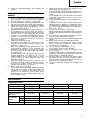 5
5
-
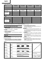 6
6
-
 7
7
-
 8
8
-
 9
9
-
 10
10
-
 11
11
-
 12
12
-
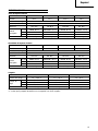 13
13
-
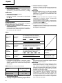 14
14
-
 15
15
-
 16
16
-
 17
17
-
 18
18
-
 19
19
-
 20
20
-
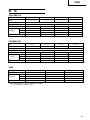 21
21
-
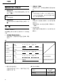 22
22
-
 23
23
-
 24
24
-
 25
25
-
 26
26
-
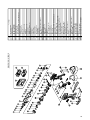 27
27
-
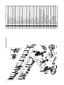 28
28
-
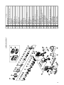 29
29
-
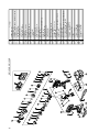 30
30
-
 31
31
-
 32
32
-
 33
33
-
 34
34


Hitachi ds 14dmr Handling Instructions Manual
- Categoría
- Destornilladores eléctricos
- Tipo
- Handling Instructions Manual
en otros idiomas
- English: Hitachi ds 14dmr
Artículos relacionados
-
Hitachi WR 14DM Handling Instructions Manual
-
-
Hitachi WR12DMR Manual de usuario
-
Hitachi WH9DM2 Manual de usuario
-
Hitachi WH14DM Handling Instructions Manual
-
Hitachi Koki WR12DAF3 El manual del propietario
-
Hitachi WH12DAF2 Manual de usuario
-
-
Hikoki WR18DBDL Manual de usuario
-
