
DESIGN + ENGINEERING
GROHE GERMANY
www.grohe.com
19 409
23 444
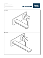
LINEARE
99.0755.031/ÄM 238657/04.18

19 409
23 444

1.
2.
12mm
2.
1.
2,5mm
32mm
*19 332
1
3
2
2.
1.
Y
Y+44
17mm
1.
29
2.
13mm
4
65
2,5mm
7

I
3mm
2,5mm
98
5 l/min
32mm
2,5mm
3mm

I
D
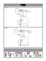
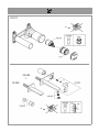
1. Maß „Y“ von der Oberkante des Unterputz-Gehäuses bis zur Fliesenoberkante ermitteln.
2. Anschlussnippel ablängen, so dass sich ein Gesamtmaß von „Y“ + 44mm ergibt.
3. Anschlussnippel mit einem 10mm Innensechskantschlüssel so in das Unterputz-Gehäuse einschrauben, dass
sich ein Einbaumaß von29mm ergibt. Auslauf mit einem 2,5mm Innensechskantschlüssel von unten befestigen.
GB
1. Determine dimension "Y" from upper edge of concealed mixer housing to the face of tiles.
2. Cut connection nipple to length so that the installation dimension is "Y" + 44mm .
3. Using a 10mm allen key, screw the connection nipple into the concealed housing so that the installation
dimension is 29mm . Tighten spout from below using a 2.5mm allen key.
F1. Mesurer la cote « Y » du bord supérieur du boîtier encastré jusqu'au bord supérieur des carreaux.
2. Couper le nipple de raccordement à la bonne longueur pour obtenir « Y »+44mm .
3. Visser le nipple de raccordement à l'aide d'une clé Alle n de 10mm dans le boîtier encastré de manière à obtenir
une dimension de montage de 29mm . Fixer le bec par le bas à l'aide d'une clé Allen de 2,5mm.
E
1. Determinar la cota "Y" desde el borde superior de la ca rcasa empotrable hasta el borde exterior de los azulejos.
2. Cortar a medida la boquilla rosca da de conexión de manera que se produ zca una cota total de "Y" + 44mm .
3. Enroscar la boquilla roscada de conexión con una lla ve de macho hexago nal de 10mm en la carcasa empotrable
de tal manera que se consiga una cota de montaje de 29mm . Fijar el caño mediante una llave de macho
hexagonal de 2,5mm por la parte inferior.
I1. Rilevare la quota "Y" dall’alloggiamento della bocca no al lo delle piastrelle.
2. Tagliare il raccordo a misura in modo da ottenere una quota complessiva di “Y” + 44mm .
3. Avvitare il raccordo con una chiave a brugola da 10 mm nell'alloggiamento della bocca in modo da ottenere una
quota di montaggio di 29mm . Fissare dal basso la bocca co n una chiave a brugola da 2,5mm.
NL
1. Bepaal de maat "Y" van de bovenkant van het ingebouwde kraanhuis tot aan de bovenkant van het tegelwerk.
2. Snijd de aansluitnippel op lengte, zodat de totale maat "Y"+44mm bedraagt.
3. Schroef de aansluitnippel met een 10mm inbussleutel zodanig in het ingebouwde kraanhuis vast, dat de
inbouwmaat 29mm bedraagt. Bevestig de uitloop van onderen met een 2,5mm inbussleutel.
S
1. Ta fram måttet ”Y” från inbyggnadshusets överkant och till kakelplattornas överkant.
2. Korta av anslutningsfästet, så att det totala måttet är “Y“+44mm .
3. Skruva fast anslutningsfästet i inbyggnadshuset med en insexnyckel 10mm, så at t monteringsmåttet är 29mm .
Fäst utloppet nedifrån med en 2,5mm insexnyckel.
DK 1. Mål afstanden "Y" fra overkanten af indmuringsdelens hus til isernes overkant.
2. Afkort tilslutningsniplen, så afstanden samlet måler "Y" + 44mm .
3. Skru tilslutningsniplen i indmuringsdelens hus med en unbr akonøgle (10 mm), så in dbygningsmålet bliver 29mm .
Fastgør udløbstuden nedefra med en unbrakonøgle (2,5mm).
N
1. Fastsett målet "Y" fra overkanten på innbyggingshuset til isoverkanten.
2. Forkort koblingsnippelen slik at man får et totalmål på "Y"+44 mm .
3. Skru koblingsnippelen inn i innbyggingshuset med en 10mm unbrakonøkkel, slik at man får et monteringsmål på
29 mm . Fest kranen fra undersiden med en 2,5mm unbrakonøkkel.
FIN 1. Mittaa mitta "Y" piiloasennuskotelon yläreunasta laatan yläreunaan.
2. Lyhennä liitäntänippaa niin , että saat kokonaismitaksi "Y" + 44mm .
3. Ruuvaa liitäntänippa 10mm:n kuusio koloavaimella piiloasennuskoteloon niin, että saat asennusmitaksi 29mm .
Kiinnitä juoksuputki 2,5mm:n kuusiokoloavaimella alhaalta.
PL
1. Wyznaczy wymiar „Y” od górnej kraw dzi korpusu podtynkowego do górnej kraw dzi p ytek.
2. Skróci z czk pod czeniow , tak aby ogólny wymiar wynosi „Y” + 44mm .
3. Wkrci z czk pod czeniow do korpusu podtynkowego przy u yciu klucza inbusowego 10mm, tak aby wymiar
monta owy wynosi 29mm . Wylewk zamocowa od do u przy u yciu klucza inbusowego 2,5mm.
UAE
GR
1. "Y"
.
2. , "Y" +44mm .
3. 10mm UP
29mm . 2,5mm .
CZ
1. Zm te rozm r „Y“ od horní hrany t lesa zapušt ného pod omítku až po horní plochu obkláda ek.
2. P ipojovací vsuvku zkra te tak, aby bylo dosaženo celkového rozm ru „Y“ + 44mm .
3. P ipojovací vsuvku zašroubujte do t lesa zapušt ného pod omítku klí em na vnit ní šestihrany 10mm tak, aby byl
dosažen montážní rozm r 29mm . Výtokové hrdlo upevnte zespodu klíem na vnit ní šestihrany 2,5mm.

I
H
1. Határozza meg a falba süllyeszthet doboz fels élét l a csempézés fels éléig tartó „Y” távolságot.
2. Vágja le a csatlakozódarabot úgy, hogy annak teljes hossza „Y”+44mm legyen.
3. Csavarozza be a csatlakozódarabot 10 mm-es imbuszkulccsal a falba süllyeszthet dobozba úgy, hogy a
beszerelési méret 29mm legyen. Rögzítse alulról a kifolyót 2,5mm-es imbuszkulccsal.
P
1. Determinar a medida "Y" da aresta superior da caixa encastrável até à aresta da parede pronta.
2. Encurtar a ligação roscada, de modo a obter numa medida total de "Y" + 44mm .
3. Aparafusar a ligação roscada (G) na caixa encastrável, usando uma chave sextavada de 10mm, de modo a
obter a medida de montagem de 29mm . Fixar a bica por baixo com uma chave sextavada de 2,5mm.
TR 1. Ankastre gövdes inin üst kenar ndan fayans yüze yine kadar olan "Y" ölçüsünü belirleyin.
2. Ba lant nipelini "Y" + 44mm ‘lik bir toplam ölçü olu acak ekilde uzat n.
3. Ba lant nipelini 10mm’lik bir alyen anahtar ile 29mm ‘lik bir montaj ölçüsü olu ana kadar ankastre-gövdesine
vidalay n. Gagay 2,5mm’lik bir alyen anahtar ile alttan tespit edin.
SK
1. Zmerajte rozmer „Y“ od hornej hrany telesa zapusteného pod omietku až po hornú plochu obklada iek.
2. Pripájaciu vsuvku skráte tak, aby celkový rozmer bol „Y“ + 44mm .
3. Pripájaciu vsuvku zaskrutkujte do tele sa zapusteného pod omietku imbusovým k úom 10mm tak, aby
montážna d žka bola 29mm . Výtokové hrdlo upevnite odspodu imbusovým k ú om 2,5mm.
SLO 1. Dolo ite mero „Y“ od zgornjega roba podometnega ohišja do zgornjega roba ploš ic.
2. Prikljuno mazalko skrajšajte, tako da dobite skupno dolžino „Y“+44mm .
3. Prikljuno mazalko z 10mm imbus klju em privijte v podometno ohišje tako, da bo vgradna mera znašala
29mm . Z 2,5mm imbus kljuem pritrdite iztok s spodnje strani.
HR
1. Utvrdite dimenziju „Y“ od gornjeg ruba podžbuknog ku išta do gornjeg ruba ploica.
2. Skratite priklju nu nazuvicu tako da ukupna dimenzija iznosi „Y“ + 44mm .
3. Uvrnite priklju nu nazuvicu u podžbukno ku ište imbus-klju em od 10mm tako da ugradna dimenzija iznosi
29mm . Slavinu pri vrstite odozdo imbus-kljuem od 2,5mm.
BG 1. „Y“
.
2. , „Y“ +44.
3. 10 ,
29 . 2,5 .
EST1. Mõõtke kaugus „Y“ peitsegisti korpuse ülemisest servast kuni plaadi ülemise servani.
2. Lühendage ühendusniplit nii palju, et üldmõõt oleks „Y“ + 44mm .
3. Kruvige ühendusnippel 10mm kuuskantvõtmega nii sügavale peitsegisti korpusesse nii, et kaugus oleks
29mm . Kinnitage segistitila 2,5mm kuuskantvõtmega altpoolt.
LV
1. Nosakiet izm ru “Y” no zemapmetuma korpusa augš j s malas l dz žu augš jai malai.
2. Sa siniet pievienošanas nipeli t , lai kop jais izm rs b tu “Y” + 44mm .
3. Ieskrv jiet pievienošanas nipeli ar 10mm iekš jo sešst raino atsl gu zemapmetuma korpus t , lai
uzstd šanas izm rs b tu 29mm . Nostipriniet izteku no apakšas ar 2,5mm iekš jo sešst raino atsl gu.
LT
1. Išmatuokite atstum „Y“ tarp potinkinio korpuso ir apdailos plytel s viršutini krašt , žr. [9] pav.
2. Jungiamj mov sutrumpinkite taip, kad bendras atstumas b t „Y“ + 44mm .
3. Jungiamj mov sukite 10mm šešiabriauniu raktu potinkin korpus taip, kad montavimo matmuo b t
29mm . Nuot kio snapelis pritvirtinamas iš apa ios šešiabriauni u raktu (2,5mm).
RO
1. Se determin cota „Y” de la marginea superioar a carcasei îngropate pân la marginea superioar a faian ei.
2. Se regleaz lungimea niplului de racordare, astfel încât s rezulte cota total de „Y“ + 44mm.
3. Folosind o cheie imbus de 10mm, se înleteaz niplul de racordare în carcasa îngropat , astfel încât s rezulte
o cot de instalare de 29mm . Se xeaz de jos dispersorul cu cheia imbus de 2,5mm.
CN 1. “Y”
2. “Y”+ 44mm
3. 10mm 29mm 2.5mm
RUS 1. «Y» .
2. , «Y» + 44 .
3.
10 , 29 .
2,5 .

1
23 444
19 409
23 571

2016/09/28
www.grohe.com
D
&
+49 571 3989 333
helpline@grohe.de
A
&
+43 1 68060
info-at@grohe.com
AUS
&
+(61) 1300 54945
grohe_australia@lixil.com
B
&
+32 16 230660
info.be@grohe.com
BG
&
+359 2 9719959
grohe-bulgaria@grohe.com
BR
&
0800 770 1222
falecom@grohe.com
CAU
&
+99 412 497 09 74
info-az@grohe.com
CDN
&
+1 888 6447643
info@grohe.ca
CH
&
+41 44 877 73 00
info@grohe.ch
CN
&
+86 4008811698
info.cn@grohe.com
CY
&
+357 22 465200
info@grome.com
CZ
&
+358 942 451 390
grohe-cz@grohe.com
DK
&
+45 44 656800
grohe@grohe.
E
&
+34 93 3368850
grohe@grohe.es
EST
&
+372 6616354
F
&
+33 1 49972900
sav-fr@grohe.com
FIN
&
+358 942 451 390
grohe@grohe.
GB
&
+44 871 200 3414
info-uk@grohe.com
GR
&
+30 210 2712908
nsapountzis@ath.forthnet.gr
H
&
+36 1 2388045
info-hu@grohe.com
HK
&
+852 2969 7067
I
&
+39 2 959401
info-it@grohe.com
IND
&
+91 1800 102 4475
customercare.in@grohe.com
IS
&
+354 515 4000
jonst@byko.is
J
&
+81 3 32989730
KZ
&
+7 727 311 07 39
info-cac@grohe.com
LT
&
+372 6616354
LV
&
+372 6616354
MAL
info-malaysia@grohe.com
MX
&
01800 8391200
pregunta@grohe.com
N
&
+47 22 072070
grohe@grohe.no
NL
&
+31 79 3680133
vragen-nl@grohe.com
NZ
technicalenquiries@paterson
trading.co.nz
P
&
+351 234 529620
commercial-pt@grohe.com
PL
&
+48 22 5432640
biuro@grohe.com.pl
RI
&
0-800-1-046743
customercare-
indonesia@asia.lixil.com
RO
&
+40 21 2125050
info-ro@grohe.com
ROK
&
+82 2 1588 5903
info-singapore@grohe.com
RP
&
+63 2 8938681
RUS
&
+7 495 9819510
info@grohe.ru
S
&
+46 771 141314
grohe@grohe.se
SGP
&
+65 6311 3611
info-singapore@grohe.com
SK
&
+420 277 004 190
grohe-cz@grohe.com
T
&
+66 21681368
(Haco Group)
TR
&
+90 216 441 23 70
GroheTurkey@grome.com
UA
&
+38 44 5375273
info-ua@grohe.com
USA
&
+1 800 4447643
us-customerservice@grohe.com
VN
&
+84 90 9694768
&
+84 90 9375068
info-vietnam@grohe.com
BiH
AL HR KS
ME MK SLO SRB
&
+385 1 2911470
adria-hr@grohe.com
Eastern Mediterranean,
Middle East - Africa
Area Sales Oce:
&
+357 22 465200
IR OM
UAE YEM
&
+971 4 3318070
grohedubai@grome.com
Far East Area Sales Oce:
&
+65 6311 3600
info@grohe.com.sg
Latin America:
&
+52 818 3050626
pregunta@grohe.com
-
 1
1
-
 2
2
-
 3
3
-
 4
4
-
 5
5
-
 6
6
-
 7
7
-
 8
8


GROHE 88766 Guía de instalación
- Tipo
- Guía de instalación
- Este manual también es adecuado para
en otros idiomas
- français: GROHE 88766 Guide d'installation
- português: GROHE 88766 Guia de instalação
- română: GROHE 88766 Ghid de instalare
Artículos relacionados
-
GROHE 88758 Guía de instalación
-
-
-
-
-
GROHE 29038001 Guía de instalación
-
-
-
-