Kichler Lighting 11146NILED Manual de usuario
- Tipo
- Manual de usuario

INSTALLATION INSTRUCTIONS
Modelo 11146LED / CP180432
Modelo 11147LED / CP180433
Modelo 11148LED / CP180434
WARNING:
• This fixture is intended for installation in accordance with the
National Electric Code (NEC) and all local code specifications.
If you are not familiar with code requirements, installation by a
certified electrician is recommended.
• This lighting fixture is suitable for indoor use, dry,
or damp locations.
• The LED light output is strong enough to injure human eyes.
Precautions must be taken to prevent looking directly at the
LED’s with unaided eyes for more than a few seconds.
DIMMING: This LED fixture is compatible with most standard
incandescent dimmers, LED dimmers, and electronic low voltage
dimmers. For optimal performance, an electronic low voltage
dimmer should be used.
CLEANING: Always be certain that electric current is turned off
before cleaning.
• Only a soft damp cloth should be used. Harsh cleaning
products may damage the finish.
CAUTION – RISK OF SHOCK – Disconnect Power at the main
circuit breaker panel or main fuse box before starting and during
the installation.
1) Attach mounting plate to outlet box with the screws provided.
a) Remove crossbar from canopy by removing four (4)
screws on back of canopy.
b) Carefully place glass onto fixture.
c) Place crossbar on top of glass and canopy. Secure with
four (4) screws removed previously.
2) Attach the grounding conductor to the mounting plate.
Secure by tightening the green ground screw. Never connect
black or white power supply wires to the grounding screw.
3) Connect the black fixture wire to the black supply wire with
a suitable wire connector. Connect the white fixture wire to
the white supply wire with a suitable wire connector.
4) Carefully push wire connections back into outlet box making
sure all connections remain secure.
5) Push decorative housing to wall.
6) Secure decorative housing to mounting plate with the
provided screws.
Date Issued: 10/31/2016 IS-11146LED-US
We’re here to help 866-558-5706
Hrs: M-F 9am to 5pm EST
SEE OTHER SIDE FOR SPANISH TRANSLATIONS.
VEA EL OTRO LADO DE TRADUCCIONES AL ESPAÑOL.
This device complies with part 15 of the FCC Rules. Operation is
subject to the following two conditions: (1) This device may not
cause harmful interference, and (2) this device must accept any
interference received, including interference that may cause un-
desired operation.
Note: This equipment has been tested and found to comply with
the limits for a Class B digital device, pursuant to part 15 of the
FCC Rules. These limits are designed to provide reasonable pro-
tection against harmful interference in a residential installation.
This equipment generates, uses and can radiate radio frequency
energy and, if not installed and used in accordance with the in-
structions, may cause harmful interference to radio communica-
tions. However, there is no guarantee that interference will not
occur in a particular installation. If this equipment does cause
harmful interference to radio or television reception, which can
be determined by turning the equipment off and on, the user is
encouraged to try to correct the interference by one or more of
the following measures:
• Reorient or relocate the receiving antenna.
• Increase the separation between the equipment and receiver.
• Connect the equipment into an outlet on a circuit different from
that to which the receiver is connected.
• Consult the dealer or an experienced radio/TV technician for
help.
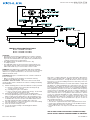
MOUNTING PLATE
NOT TO SCALE
MOUNTING SCREWS
CANOPY
END CAP
END CAP SCREWS
DIFFUSER
MOUNTING PLATE SCREWS
FIXTURE
PLASTIC WALL ANCHORS
WALL ANCHOR SCREWS
WIRE NUTS
MODULE WIRES
GROUND WIRE
57012A24
P/N: 661-0120 R1.0
CCT: 3000K 4000K 5000K VF BIN:
CN1
-
+
D1
+
D24
+
D2
+
D3
+
D4
+
D5
+
D6
+
D7
+
D8
+
D9
+
D10
+
D11
+
D12
+
D13
+
D14
+
D15
+
D16
+
D17
+
D18
+
D19
+
D20
+
D21
+
D22
+
D23
+
SIDE VIEW:

Date Issued: 10/31/16 IS-11146LED-US
SEE OTHER SIDE FOR ENGLISH TRANSLATIONS.
VEA EL OTRO LADO DE TRADUCCIONES AL INGLÉS.
INSTRUCCIONES DE INSTALACIÓN
Modelo 11146LED / CP180432
Modelo 11147LED / CP180433
Modelo 11148LED / CP180434
ADVERTENCIA:
• Este artefacto está diseñado para instalarse conforme al
Código Nacional de Electricidad (NEC, por sus siglas en
inglés) y a todas las especificaciones de códigos locales. Si
no está familiarizado con los requisitos del código, se reco-
mienda que la instalación la realice un electricista certificado.
• Este artefacto de iluminación es adecuado para usarse en
interiores, en lugares secos, o húmedos.
• La luz LED que se obtiene es suficientemente fuerte como
para dañar los ojos. Deben tomarse precauciones para
prevenir mirar directamente la luz LED sin protección por más
de unos cuantos segundos.
REGULACIÓN DE INTENSIDAD DE LUZ: Este artefacto LED es
compatible con la mayoría de los reguladores de intensidad
incandescentes estándares, los reguladores de intensidad LED,
y los reguladores de intensidad de bajo voltaje electrónicos.
Para un desempeño óptimo, debería usarse un regulador de
intensidad de bajo voltaje electrónico.
PRECAUCIÓN – RIESGO DE DESCARGA ELÉCTRICA – Desco-
necte la electricidad en el panel principal del interruptor au-
tomático o caja principal de fusibles antes de comenzar y
durante la instalación.
LIMPIEZA: Asegúrese siempre de que la corriente eléctrica esté
apagada antes de limpiar.
• Debe usarse solamente una tela húmeda y suave. Productos
de limpieza abrasivos pueden dañar el acabado.
1) Fije la placa de montaje a la caja de salida con los tornillos
suministrados.
a) Remueva el larguero del escudete sacando cuatro
tornillos en la parte de atrás del escudete.
b) Coloque cuidadosamente el vidrio en el artefacto.
We’re here to help 866-558-5706
Hrs: M-F 9am to 5pm EST
c) Coloque el larguero arriba del vidrio y del escudete.
Asegure con los cuatro tornillos removidos previamente.
2) Sujete el conductor de tierra a la placa de montaje. Asegure
apretando el tornillo de tierra verde. Nunca conecte los
alambres de alimentación eléctrica negro o blanco al tornillo
de tierra.
3) Conecte el alambre negro del artefacto al alambre negro de
alimentación con un conector de alambre apropiado.
Conecte el alambre blanco del artefacto al alambre blanco
de alimentación con un conector de alambre apropiado.
4) Empuje cuidadosamente las conexiones de cable dentro de
la caja de conexiones, asegurándose que todas las conexio
nes permanecen seguras.
5) Empuje la cubierta ornamental a la pared.
6) Fije la cubierta ornamental a la pared con de montaje a la
caja suministrados.
Este artefacto cumple con la parte 15 de las Normas de la FCC. El funcionamiento está sujeto a las siguientes dos condiciones: (1) Este
artefacto no puede causar interferencia perjudicial, y (2) este artefacto debe aceptar cualquier interferencia recibida, inclusive interferencia
que puede causar una operación no deseada.
Nota: Este equipo ha sido probado y se comprobó que cumple con los límites para un artefacto digital Clase B, de conformidad con la parte
15 de las Normas de la FCC. Estos límites están diseñados para proporcionar una protección razonable contra interferencia perjudicial en
una instalación residencial. Este equipo genera, usa y puede radiar energía de radio frecuencia y, si no se instala y usa de acuerdo con las
instrucciones, puede causar interferencia perjudicial a las comunicaciones de radio. Sin embargo, no hay garantía que la interferencia no
ocurrirá en una instalación en particular. Si este equipo sí causa interferencia perjudicial a la recepción de radio o televisión, que puede ser
determinado encendiendo y apagando el equipo, se alienta al usuario a que trate de corregir la interferencia con una o más de las siguientes
medidas:
• Reoriente o cambie de lugar la antena de recepción.
• Aumente la separación entre el equipo y el receptor.
• Conecte el equipo en un receptáculo en un circuito diferente de donde está conectado el receptor.
• Consulte al distribuidor o a un técnico de radio/TV experimentado para ayuda.
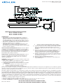
PLACA DE MONTAJE
NO A ESCALA
TORNILLOS DE MONTAJE
ESCUDETE
TAPA DE EXTREMO
TORNILLOS DE TAPA DE EXTRMO
DIFUSOR DE
TORNILLOS DE LA PLACA DE MONTAJE
ARTIFACTO
TAQUETES DE PLÁSTICO
TORNILLOS DE ANCLAJE DE PARED
TUERCAS DE MARIPOSA
CABLES DEL MÓDULO
CABEL A TIERRA
57012A24
P/N: 661-0120 R1.0
CCT: 3000K 4000K 5000K VF BIN:
CN1
-
+
D1
+
D24
+
D2
+
D3
+
D4
+
D5
+
D6
+
D7
+
D8
+
D9
+
D10
+
D11
+
D12
+
D13
+
D14
+
D15
+
D16
+
D17
+
D18
+
D19
+
D20
+
D21
+
D22
+
D23
+
VISTA LATERAL:
-
 1
1
-
 2
2


Kichler Lighting 11146NILED Manual de usuario
- Tipo
- Manual de usuario
en otros idiomas
Artículos relacionados


Otros documentos
-
Tripp Lite S3M 3-Phase UPS Systems S3M10-20kVA MODBUS Protocol El manual del propietario
-
-
Hunter 90065 Guía de instalación
-
Hunter Fan 82023 Manual de usuario
-
-
 Hunter Fan LA STRADA 82022 Manual de usuario
-
-
 Hunter Fan 43041-01 Manual de usuario
-

