dBTechnologies RS16000 Touring Rack El manual del propietario
- Categoría
- Equipo de música suplementario
- Tipo
- El manual del propietario

MANUALE D’USO – Sezione 1
USER MANUAL - Section 1
BEDIENUNGSANLEITUNG - Abschnitt 1
CARACTERISTIQUES TECHNIQUES - Section 1
MANUAL DEL USUARIO - Sección 1
Le avvertenze nel presente manuale devono essere osservate congiuntamente al “MANUALE D’USO - Sezione2”.
The warnings in this manual must be observed together with the “USER MANNUAL- Section 2”.
Die Warnungen in diesem Handbuch müssen in Verbindung mit der “BEDIENUNGSANLEITUNG - Abschnitt 2” beobachtet werden”.
Les avertissements speciés dans ce manuel doivent être respectés ainsi que les “CARACTERISTIQUES TECHNIQUES -Section 2”.
Las advertencias del presente manual se deben tener en cuenta conjuntamente con las del “Manual del usuario” - Sección 2”.

RED CERTIFICATION
EMI CLASSIFICATION
This equipment is in conformity with RED directive 2014/53/EU in reference to the following harmonized
standards:
Health EN 62479:2010
Safety EN 62368-1:2014+A11
EMC EN 301 489-1 v2.2.0, EN 301 489-9 v2.1.1, EN 301 789-17 V3.2.0,
EN 55032:2015, EN 55035:2017
Spectrum EN 301 422-1 v2.1.2, EN 300 328 v2.1.1
This equipment has been designed and complies with the safety requirements for portable (<20 cm) RF exposure
in accordance with FCC rule part 2.1091. Installers must ensure that this device must not be co-located or operated
in conjunction with any other antenna or transmitter except in accordance with FCC multi-transmitter product
procedures.
According to the standards EN 55032 and EN 55035 this equipment is designed and suitable to operate in class B
electromagnetic environments.
FCC AND IC CERTIFICATION
RS16000 body – FCC ID:2ADDV-RS16000B
RS16000 body – IC ID:12207A-RS16000B
RS16000 Hand – FCC ID:2ADDV-RS16000H
RS16000 Hand – IC ID:12207A-RS16000H
NOTICE
For USA Market:
This equipment has been tested and found to comply with the limits for a Class B digital device, pursuant to part
15 of the FCC Rules. These limits are designed to provide reasonable protection against harmful interference
in a residential installation. This equipment generates, uses and can radiate radio frequency energy and, if not
installed and used in accordance with the instructions, may cause harmful interference to radio communications.
However, there is no guarantee that interference will not occur in a particular installation. If this equipment does
cause harmful interference to radio or television reception, which can be determined by turning the equipment
off and on, the user is encouraged to try to correct the interference by one or more of the following measures:
—Reorient or relocate the receiving antenna.
—Increase the separation between the equipment and receiver.
—Connect the equipment into an outlet on a circuit different from that to which the receiver is connected.
—Consult the dealer or an experienced radio/TV technician for help.
Changes or modications not expressly approved by the party responsible for compliance could void the user’s
authority to operate the equipment.
EN 300422-1 V.2.1.2
E
N 301357 V.2.1.1
E
N 301489-1 V.2.1.1
E
N 301489-9 V.2.1.1
E
N 62311 :2008
EN 60065 :2014
Radio Spectrum
EMC
Healty and Safety
2
RS16000TR
Cod. 420120285 REV. 1.0

CONSUMER ALERT
Most users do not need a license to operate this wireless system. Nevertheless, operating this microphone system
without a license is subject to certain restrictions: The system may not cause harmful interference; it must operate
at a low power level (not in excess of 50 milliwatts); and it has no protection from interference received from any
other device. Purchasers should also be aware that the FCC is currently evaluating use of wireless microphone
systems, and these rules are subject to change. For more information, call the FCC at 1-888-CALL-FCC (TTY:
1-888-TELL-FCC) or visit the FCC’s wireless microphone Web site at http://www.fcc.gov/cgb/wirelessmicrophones.
For Canadian Market:
This device complies with Industry Canada’s license-exempt RSSs.
Operation is subject to the following two conditions:
(1) This device may not cause interference; and
(2) This device must accept any interference, including interference that may cause undesired operation of the
device.
This device operates on a no-protection no-interference basis. Should the user seek to obtain protection from
other radio services operating in the same TV bands, a radio license is required.
Please consult Industry Canada’s document CPC-2-1-28, Optional Licensing for Low-Power Radio Apparatus in the
TV Bands, for details.
IMPORTANT SAFETY INSTRUCTIONS:
1. Read these instructions
2. Keep these instructions.
3. Heed all warnings.
4. Follow all instructions.
5. Do not use this apparatus near water.
6. Clean only with dry cloth.
7. Do not block any ventilation openings. Install in accordance with the manufacturer’s instructions.
8. Do not install near any heat sources such as radiators, heat registers, stoves, or other apparatus (including
ampliers) that produce heat.
9. Do not defeat the safety purpose of the polarized or grounding-type plug. A polarized plug has two blades
with one wider than the other. A grounding type plug has two blades and a third grounding prong. The wide
blade or the third prong are provided for your safety. If the provided plug does not t into your outlet, consult an
electrician for replacement of the obsolete outlet.
10. Protect the power cord from being walked on or pinched particularly at plugs, convenience receptacles, and
the point where they exit from the apparatus.
11. Only use attachments /accessories specied by the manufacturer.
12.
Use only with the cart, stand tripod, bracket, or table specied by the manufacturer, or sold with
the apparatus. When a cart is used, use caution, when moving the cart/apparatus combination to avoid injury
from tip-over.
13. Unplug this apparatus during lightning storms or when unused for long periods of time.
14. Refer all servicing to qualied service personnel. Servicing is required when the apparatus has been damaged
in any way, such as power-supply cord or plug is damaged, liquid has been spilled or objects have fallen into the
apparatus has been exposed to rain or moisture, does not operate normally, or has been dropped.
ADDITIONAL SAFETY INSTRUCTIONS:
• No naked ame sources, such as lighted candles, should be placed on the apparatus
• Do not use the apparatus in tropical climates
3
RS16000TR Cod. 420120285 REV. 1.0


5
RS16000TR Cod. 420120285 REV. 1.0
INDICE
Italiano
INDICE
1. INFORMAZIONI GENERALI ................................................................................................... 6
BENVENUTI! ........................................................................................................................ 6
PANORAMICA INTRODUTTIVA .......................................................................................... 6
RIFERIMENTI PER L’UTENTE ................................................................................................ 6
CONTENUTO - USO DEL FLIGHT CASE ............................................................................... 7
2. STRUTTURA DEL SISTEMA E ACCESSORI PRINCIPALI ........................................................ 8
RADIOMICROFONI OPZIONALI .......................................................................................... 8
ANTENNE ATTIVE OPZIONALI ............................................................................................ 8
LATO FRONTALE DEL SISTEMA .......................................................................................... 9
LATO POSTERIORE DEL SISTEMA ..................................................................................... 10
CORRISPONDENZA DELLE USCITE AUDIO ....................................................................... 10
RS16000H .......................................................................................................................... 11
RS16000B........................................................................................................................... 11
3. PRIMA ACCENSIONE E SINCRONIZZAZIONE .................................................................... 12
SINCRONIZZAZIONE CON RS16000H ............................................................................... 13
SINCRONIZZAZIONE CON RS16000B ............................................................................... 13
4. IL RICEVITORE RS16000R ..................................................................................................... 14
CARATTERISTICHE PRINCIPALI E INTERFACCIA UTENTE ................................................. 14
SCHERMATA INIZIALE ....................................................................................................... 14
QUICK SETUP .................................................................................................................... 15
SYNC .................................................................................................................................. 15
TX PAR 1 ............................................................................................................................ 15
TX PAR 2 ............................................................................................................................ 15
RX PAR ............................................................................................................................... 16
MANUAL FREQ MODE...................................................................................................... 16
NOISE GATE ....................................................................................................................... 16
RX INFO ............................................................................................................................. 16
5. HUB800, AS6W, RPS10 ......................................................................................................... 17
HUB800 ............................................................................................................................. 17
AS6W ................................................................................................................................. 17
RPS10 ................................................................................................................................. 17
6. UTILIZZO DELLE ANTENNE ................................................................................................. 18
7. CONTROLLO REMOTO ......................................................................................................... 19
8. SISTEMI MULTIMICROFONICI ............................................................................................. 20
9. AGGIORNAMENTO DEL FIRMWARE .................................................................................. 21
10. PRIMA RISOLUZIONE DEI PROBLEMI .............................................................................. 22
11. SPECIFICHE TECNICHE ....................................................................................................... 23

6
RS16000TR
Cod. 420120285 REV. 1.0
1. INFORMAZIONI GENERALI
BENVENUTI!
PANORAMICA INTRODUTTIVA
RIFERIMENTI PER L’UTENTE
Grazie per aver acquistato un prodotto progettato e sviluppato in Italia da dBTechnologies! Questo kit multi-
microfonico a modulazione digitale è frutto di una lunga esperienza nel campo della trasmissione radio digitale
applicata al campo audio. Impiega soluzioni ottimizzate per una facile congurazione e robustezza di utilizzo.
RS16000TR è un sistema professionale multimicrofonico a rack, racchiuso in un pratico ight case. Può lavorare, a
seconda dei limiti dei Paesi di utilizzo, in tutta la banda UHF, da 470 a 865 MHz. Questo si traduce in una versatilità
che ne consente l’utilizzo anche in scenari futuri, in caso di eventuale ridenizione delle bande ammesse (tramite
un semplice aggiornamento rmware).
Il sistema è caratterizzato dai seguenti componenti:
Per utilizzare al meglio il vostro RS16000TR consigliamo di:
• 6 ricevitori RS16000R di ultima generazione, a larga banda con true diversity (portata no a 100 m in
campo libero)
• 1 distributore di antenna AS6W in banda UHF che può fornire alimentazione phantom da 9 V ad
eventuali antenne attive opzionali
• 1 dispositivo di rete HUB800, che consente il controllo remoto del Touring Rack da parte di un PC,
tramite il software dBTechnologies Wireless Manager (è quindi possibile il controllo di più sistemi
connessi)
• Radiomicrofoni handheld o body a modulazione digitale (rispettivamente RS16000H RS16000B),
disponibili come accessori
• Antenne attive, direttive (DA-RS16) o ominidirezionali (FA-RS16), che consentono di ottimizzare la
ricezione, a seconda delle esigenze di ogni ambiente di utilizzo, sono disponibili come accessori
• leggere il manuale d’uso quick start presente nella confezione e questo manuale d’uso completo in
ogni sua parte e conservarlo per tutta la durata di vita del prodotto.
• registrare il prodotto sul sito http://www.dbtechnologies.com nella sezione “SUPPORTO”.
• conservare prova d’acquisto e GARANZIA (Manuale d’uso “sezione 2”).
Italiano

1
1
2
1
1
2
7
RS16000TR Cod. 420120285 REV. 1.0
Italiano
CONTENUTO - USO DEL FLIGHT CASE
Borse porta radiomicrofoni Cavo di
alimentazione
VDE
Cavo USB Antenne di primo
utilizzo
Aprire il ight case operando sulle chiusure a farfalla [1].
Asportarne il lato frontale e posteriore [2] ed estrarre dalla borsa all’interno il contenuto, illustrato nella gura
sotto.
Documentazione cartacea

8
RS16000TR
Cod. 420120285 REV. 1.0
Italiano
2. STRUTTURA DEL SISTEMA E ACCESSORI PRINCIPALI
ANTENNE DI PRIMO UTILIZZO
AS6W - ANTENNA SPLITTER
RS16000R - RICEVITORI (6 x)
HUB800 - NETWORK HUB
RACK OUTPUTS
RPS10 - POWER SUPPLY UNIT
PANNELLO VENTOLE
MICROFONO BODY
MICROFONO MANO
RADIOMICROFONI OPZIONALI ANTENNE ATTIVE OPZIONALI
La struttura di RS16000TR è descritta in gura.
Sul lato frontale sono presenti i pannelli anteriori di comando di AS6W, HUB800, e dei 6 ricevitori RS16000R.
Sul lato posteriore sono presenti i pannelli con i connettori di output e di alimentazione.
RS16000TR è già cablato internamente e pronto all’uso, l’eventuale rimozione del PANNELLO VENTOLE e l’accesso
all’interno può avvenire solo sotto opportune condizioni presentate più avanti).
Qui sotto sono presentati gli accessori principali del sistema.
ANTENNA
OMNIDIREZIONALE
ANTENNA DIRETTIVA

A
B
C
C
D
E F
G
L
H
I
M N
P
O
Q
T
R
S
9
RS16000TR Cod. 420120285 REV. 1.0
LATO FRONTALE DEL SISTEMA
AS6W
HUB800
A LED Phantom Power - se acceso (luce rossa) la phantom power è attiva
B LED Power - se acceso (luce verde) A6W è acceso
C Antenne in dotazione
D Porta USB tipo B
F Manopola Select-Push - se ruotata seleziona, se premuta conferma una scelta
G Interfaccia I.R.
H Tasto Up
I Tasto Down
L Tasto Esc
RS16000R
M Tasto STAND BY
N Led di intensità del segnale audio (V meter)
O Display
P Manopola Select-Push - se ruotata seleziona, se premuta conferma una scelta
Q Interfaccia I.R.
R Tasto Up
S Tasto Down
T Tasto Esc
Italiano

U
V
W
X
Y
Z
10
RS16000TR
Cod. 420120285 REV. 1.0
LATO POSTERIORE DEL SISTEMA
Outputs
RPS10
U 6 uscite microfoniche
V Connettore di uscita di rete (Ethernet)
W Connettore VDE con fusibile
X Interruttore ON-OFF
Y Led Power ON
Z LED di alimentazione delle sezioni del rack
1
1
2
2
3
4
5
6
3
4
5
6
N.B. Le uscite audio sono di default a livello microfonico. Per eventuale modica a “Line” delle uscite del sistema fare riferimento al
capitolo “Aggiornamento del rmware” che mostra l’accesso all’interno del rack, consentito solo in questi casi, e che è riservato al
solo personale esperto.
CORRISPONDENZA DELLE USCITE AUDIO
Italiano

1
2
3
4
5
6
+
+
I.R.
1
2
3
4
5
6
On/Off and MUTE button
Display
IR port
Battery cover
Mic cover
Battery compartment
Main controls
1
2
3
4
5
6
+
+
3
4
3
8
6
2
5 1
7
Made in ITALY
CAUTION, RISK OF EXPLOSION IF BATTERY
IS REPLACED BY AN INCORRECT TYPE.
D
ISPOSE OF USE BATTERIES ACCORDING
TO THE INSTRUCTIONS.
1.5V AA
1.5V AA
7
8
On/Off and MUTE button
Mini XLR connector
Battery cover
Open buttons
status LEDs
display
IR port
Battery compartment
Main controls
11
RS16000TR Cod. 420120285 REV. 1.0
RS16000H
RS16000B
RS16000H è un trasmettitore palmare dotato di capsula
cardioide dinamica intercambiabile. Un anello adattatore
(incluso) lo può rendere compatibile con capsule SHURE.
L’illustrazione a anco riporta le dotazioni principali:
• Per l’utilizzo sono necessarie 2 batterie tipo AA.
Il relativo alloggiamento [6] si apre svitandone il
coperchio [4].
• L’interfaccia IR [3] è nascosta dal coperchio [4].
• Una volta che il radiomicrofono è stato acceso con il
tasto [1], lo stesso tasto, premuto per circa 1 secondo
abilita/disabilita la funzione MUTE. L’avanzamento
fra schermate avviene premendo brevemente il tasto
[1]
• Il display [2] mostra nome, frequenza, indicazione
di MUTE, livello della batteria, guadagno capsula e
potenza di trasmissione
• La congurazione ed il monitoraggio avviene tramite
il display del ricevitore RS16000R, dopo opportuna
sincronizzazione con questo dispositivo (si veda il
capitolo successivo)
• Il guadagno si regola solo, dopo opportuna
sincronizzazione, attraverso il controllo dal ricevitore
RS16000R
• Quando il radiomicrofono non è utilizzato per un
lungo periodo si consiglia di rimuovere le batterie
1 Tasto On/Off e MUTE
2 Display
3 Interfaccia IR
4 Coperchio batteria
5 Protezione della capsula
6 Alloggiamento della batteria
1 Tasto On/Off e MUTE
2 Mini connettore XLR
3 Coperchio batteria
4 Sblocco del coperchio
5 Led di stato
6 Display
7 Interfaccia IR
8 Alloggiamento della batteria
RS16000B è un trasmettitore bodypack. Grazie ad un
connettore mini XLR può essere utilizzato, oltre che con
un microfono lavalier, od un headset, anche con uno
strumento musicale (es. chitarra elettrica). L’illustrazione
a anco riporta le dotazioni principali:
• Per l’utilizzo sono necessarie 2 batterie tipo AA.
Il relativo alloggiamento [8] si apre agendo sugli
sblocchi [4].
• L’interfaccia IR [7] è visibile sul lato del
radiomicrofono.
• Una volta che il radiomicrofono è stato acceso con il
tasto [1], lo stesso tasto, premuto per circa 1 secondo
abilita/disabilita la funzione MUTE
• Il display [6] mostra nome, frequenza, indicazione
di MUTE, livello della batteria, guadagno audio
e potenza di trasmissione. L’avanzamento fra
schermate avviene premendo brevemente il tasto [1]
• La congurazione ed il monitoraggio avviene tramite
il display del ricevitore RS16000R, dopo opportuna
sincronizzazione con questo dispositivo (si veda il
capitolo successivo)
• Il guadagno si regola agendo direttamente sui due
pulsanti “+” “-” interni al vano [8].
• Quando il radiomicrofono non è utilizzato per un
lungo periodo si consiglia di rimuovere le batterie
Italiano

ITA
Tx Name
bank i3 (67) 01
channel 01
Freq 470.100 MHz
12
RS16000TR
Cod. 420120285 REV. 1.0
Italiano
3. PRIMA ACCENSIONE E SINCRONIZZAZIONE
Alla prima accensione seguire i passi qui indicati (si riferiscono ad un primo utilizzo con le antenne in dotazione):
a) sul lato frontale, inserire ed avvitare le antenne in dotazione negli appositi connettori BNC di A6W.
b) sul retro, inserire il cavo VDE in dotazione (opportunamente connesso alla rete elettrica) e premere il pulsante
su ON. In sequenza, i LED di RPS10 segnalano l’avvenuta alimentazione di tutte le sezioni di RS16000TR.
c) sul lato frontale, i led di AS6W segnalano che le antenne sono alimentate. I display si accendono. In particolare
quelli dei ricevitori RS16000R mostrano una schermata simile a quella riportata in gura.
VDE
ON/OFF

13
RS16000TR Cod. 420120285 REV. 1.0
Italiano
SINCRONIZZAZIONE CON RS16000H
SINCRONIZZAZIONE CON RS16000B
d) una volta inserite
le batterie ed acceso il
radiomicrofono:
• selezionare sul ricevitore
RS16000R la schermata
“QUICK SETUP”
premendo il tasto “Up”.
• Svitare il coperchio batteria del
radiomicrofono, in modo da rendere visibile
l’interfaccia IR dello stesso.
• Su RS16000R selezionare e confermare con la
manopola “Select/Push” l’opzione a schermo
“Sync Rx -> Tx.
• Avvicinare le due interfacce IR in modo che
siano l’una di fronte all’altra a una distanza
massima di 20 cm.
d) una volta inserite
le batterie ed acceso il
radiomicrofono:
• selezionare sul ricevitore
RS16000R la schermata
“QUICK SETUP”
premendo il tasto “Up”.
• Aprire il coperchio batteria del
radiomicrofono, in modo da poter accedere ai
tasti interni “+” e “-”
• Su RS16000R selezionare e confermare con la
manopola “Select/Push” l’opzione a schermo
“Sync Rx -> Tx.
• Sul radiomicrofono, per circa 1 secondo,
tenere premuti contemporaneamente i tasti
“+” e “-”.
• Avvicinare le due interfacce IR in modo che
siano l’una di fronte all’altra a una distanza
massima di 20 cm.

ITA Tx Name
bank i3 (67) 01
channel 01
Freq 470.100 MHz
bank i3 (67) 01
14
RS16000TR
Cod. 420120285 REV. 1.0
Italiano
4. IL RICEVITORE RS16000R
CARATTERISTICHE PRINCIPALI E INTERFACCIA UTENTE
RS16000R è un ricevitore professionale che può lavorare, a seconda dei limiti dei Paesi di
utilizzo, in tutta la banda UHF, da 470 a 865 MHz. Caratterizzato da un sistema a modulazione
digitale che garantisce notevole immunità alle interferenze, è dotato di diverse funzioni che ne
permettono il controllo in tempo reale e da remoto. In questo paragrafo si approfondiscono
le varie schermate che appaiono all’utente ed i relativi parametri. La selezione e l’incremento-
decremento dei valori avviene tramite i controlli [P], [R], [S], [T]. In particolare l’avazamento/
ritorno tra una schermata e un’altra avviene attraverso i tasti “UP” [R], oppure “DOWN” [S].
All’interno della schermata, invece, la selezione/conferma avviene con la manopola [P], ruotata
oppure premuta. Il tasto “ESC” [T] riporta subito alla schermata iniziale.
La modica dei vari parametri avviene generalmente sul ricevitore (o da remoto), di
conseguenza questi sono passati al trasmettitore dopo la sincronizzazione a infrarossi.
SCHERMATA INIZIALE
1. Paese di utilizzo [M]
2. Nome utente associato al trasmettitore sincronizzato
3. Simbolo MUTED/UNMUTED
4. Indicatore di intensità del segnale di antenna A
5. Indicatore di intensità del segnale di antenna B
6. Indicatore del livello di disturbo in ingresso
7. Banco, secondo la formattazione qui a anco [M]
8. Canale [M]
9. Frequenza di sintonizzazione
10. Ricezione del trasmettitore
11. Livello della batteria del trasmettitore
M N
P
O
Q
T
R
S
BNC -> ANTENNA A
BNC -> ANTENNA B
CONNETTORE DI RETE
USCITA AUDIO BILANCIATA CON SELETTORE “MIC/LINE”
USCITA AUDIO SBILANCIATA “LINE”
CONNETTORE DI ALIMENTAZIONE
CONNETTORE USB
M Tasto ON-STAND BY
N Led di intensità del segnale audio
O Display
P Manopola Select-Push
Q Interfaccia I.R.
R Tasto Up
S Tasto Down
T Tasto Esc
N.B. Il retro di RS16000R è mostrato
a puro titolo informativo. L’accesso
all’interno del rack RS16000TR è ammesso
esclusivamente in casi particolari, vedi il
capitolo “Aggiornamento del rmware”
I parametri visualizzabili in questa schermata sono
presentati qui sotto. In questo elenco si evidenziano quelli
modicabili con la lettera [M]:
ORDINE DI INTERMODULAZIONE
CANALI DISPONIBILI
BANCO
1
2
3
4
5
6
7
8
9
10
11

QUICK SETUP
Quick scan
Sync Rx -> Tx
SYNC
Rx -> Tx
Tx -> Rx
TX PAR 1
Name
Gain
RF Power
TX PAR 2
Encrypt
Type
SingerName
0 dB
50 mW
OFF
OFF
Body
Button Lock
15
RS16000TR Cod. 420120285 REV. 1.0
Italiano
Permette di effettuare immediatamente una
sincronizzazione sulla base del canale migliore per il
ricevitore:
• tramite “QUICK SCAN” il sistema rileva il canale
migliore
• tramite “Sync Rx -> Tx” avviene la sincronizzazione,
con la procedura descritta nel paragrafo relativo, ed il
ricevitore assegna tale canale al trasmettitore
Effettua la sincronizzazione in modo manuale:
• (Rx -> Tx) vengono scritti sul trasmettitore,
i parametri dei menu TX PAR1 e TX PAR2 del ricevitore
• (Tx -> Rx) vengono letti i parametri del trasmettitore e
salvati sul ricevitore
Consente di impostare:
• il nome “Name” associato al trasmettitore
• il guadagno “Gain” su un trasmettitore RS16000H, con
possibili valori [-10, -4, 0, +6, +10, +23] dB
• scegliere la potenza di trasmissione “RF Power”, con
possibili valori [10, 50] mW
QUICK SETUP
SYNC
TX PAR 1
Permette di:
• utilizzare una codica di trasmissione “Encrypt”, che
se abilitata, rende decifrabile il trasmettitore associato
solo da questo particolare ricevitore
• utilizzare una funzione blocca-tasti sul trasmettitore
(“Button Lock”)
• rilevare il tipo di trasmettitore (Body/Handheld)
“Type” sincronizzato in quel momento
TX PAR 2

NOISE GATE
Threshold
Attack
Release
RX INFO
FW ver Rx
Factory Reset
FW ver DSP
0 ms
0 ms
OFF dB
eu
RX PAR
Out Att
Rx - HUB
Out Level
MANUAL FREQ MODE
Manual Mode
Frequency
0 dB
Mic
ID 3
OFF
621.100
16
RS16000TR
Cod. 420120285 REV. 1.0
Italiano
Permette di:
• abilitare/disabilitare la modalità manuale di selezione
manuale della frequenza
• impostare la frequenza manualmente, con step di 25
kHz
Permette di:
• impostare il livello di attenuazione in dB “Out Att” in
uscita audio, con range [0 ÷ -99] dB (estremo: MUTE)
• segnala il tipo di ivello audio in uscita, microfonico/di
linea “Out Level”
• vedere l’ ID “Rx Hub” associato per la connessione in
rete di quello specico ricevitore (gli id sono associati
automaticamente tra i valori [1-255])
RX PAR
MANUAL FREQ MODE
Consente di operare sull’intervento del NOISE GATE (utile
ad esempio nel caso di utilizzo di una chitarra elettrica
con overdrive):
• denendo l’attacco in ms (range: [0 ÷ 26 ms ])
• denendo il rilascio in ms (range: [0 ÷ 51ms ])
• impostando la soglia di intervento in dB
(range [-49 ÷ 1.8] dB)
NOISE GATE
Consente di visualizzare informazioni utili su:
• versione rmware del ricevitore “FW ver Rx”
• versione rmware del DSP “FW ver DSP”
• reimpostare le impostazioni di fabbrica “Factory
Reset”
RX INFO

17
RS16000TR Cod. 420120285 REV. 1.0
5. HUB800, AS6W, RPS10
HUB800
AS6W
RPS10
HUB800 è l’interfaccia che permette il controllo in rete dei 6 ricevitori di RS16000TR da parte
di un PC.
La connessione avviene tramite la porta anteriore (USB) o posteriore (ETHERNET) indicata in
gura.
Il controllo locale è afdato ai 3 tasti UP, DOWN, ed ESC, ed ad una manopola Select-Push sul
lato frontale. Sul display sono mostrati i parametri di congurazione.
Per un corretto funzionamento tutti i ricevitori devono essere impostati sullo stesso Paese e
Banco.
Nella schermata principale del display, fra le altre indicazioni:
• in alto a sinistra un indicatore mostra il tipo di connessione (a rete, a PC, a PC tramite Rete)
• nei riquadri al centro e a destra sono presenti gli indicatori dei trasmettitori, se associati, e
vengono mostrati i livelli della batteria, il canale utilizzato, l’intensità del segnale ricevuto
dal ricevitore.
AS6W è un’antenna splitter, con 2 ingressi a connettore BNC e guadagno tipico 3dB. L’impedenza di ingresso è 50
ohm, come quella di uscita. La Phantom Power fornisce alimentazione da 9V e la sua accensione è segnalata dal
relativo LED frontale.
RPS10, oltre a fornire alimentazione in modo sistematico alle varie sezioni di RS16000TR:
• garantisce protezione dalle sovracorrenti su ogni singola linea di alimentazione
• interviene su eventuali cortocircuiti disabilitando la linea e segnalando all’utente il problema con un
lampeggio al secondo del led relativo
In questo paragrafo si aggiungono informazioni tecniche su alcuni componenti di RS16000TR.
IT
Bank 01
Ch01
Ch03
Ch02
Ch04
Ch05 Ch06
Italiano

Italiano
18
RS16000TR
Cod. 420120285 REV. 1.0
6. UTILIZZO DELLE ANTENNE
Sono disponibili, come opzionali, due tipi di
antenne:
- FA-RS16 antenna attiva omnidirezionale
- DA-RS16 antenna attiva direttiva, con
pattern di radiazione di tipo cardioide.
Per entrambe:
• l’utilizzo è a coppie, e possono essere
montate su aste microfoniche grazie ad
una predispozione meccanica
• si collegano tramite connettore BNC al
modulo AS6W, che fornisce l’alimentazione
phantom a 9V
• è previsto un selettore di guadagno per
adattare il segnale al percorso del cavo
con connettori BNC. I guadagni applicabili
sono:
1. -6 dB
2. 0 dB
3. 6 dB
4. 12 dB
In tabella sono riportati i guadagni consigliati
in dipendenza dal cavo:
• è presente un indicatore di picco (LED
PEAK) che consente di visualizzare quando
il segnale dal trasmettitore è troppo
intenso e può portare a saturazione.
Generalmente è sufciente allontanare il
trasmettitore dal ricevitore per risolvere il
problema.
• è consigliato l’utilizzo delle antenne ad
un’altezza minima di 1,8 m da terra, in
linea di propagazione diretta a vista (line-
of-sight)
• è preferibile distanziare il più possibile in
ogni coppia un’antenna dall’altra
Fig. 1
Italiano

Italiano
19
RS16000TR Cod. 420120285 REV. 1.0
7. CONTROLLO REMOTO
Il software che permette di controllare RS16000TR da remoto tramite PC è “dBTechnologies
Wireless Manager”. Permette di accedere in remoto a tutti i parametri dei ricevitori RS16000TR.
Una volta installato su PC:
• tramite connessione USB consente il controllo di 1 RS16000TR
• tramite connessione di rete ETHERNET consente il controllo di più RS16000TR (vedi il capitolo
“SISTEMI MULTIMICROFONICI”)
Per utilizzare il software:
1) scaricare ed installarlo sul PC
2) connettere la sezione HUB800 di RS16000TR tramite cavo con connettori USB (frontale) oppure
con connettori RJ45 (cavo Ethernet, lato posteriore), vedi anche le gure a lato.
3) al lancio del software la connessione è mostrata immediatamente, se USB, oppure con la
funzione CONNECTION -> DISCOVERY se ETHERNET
Le caratteristiche di “dBTechnologies Wireless Manager”:
• ad ogni ricevitore è assegnato un ID automaticamente
• con un click sopra alla schermata di monitoraggio del ricevitore (g. 1) si passa alla schermata
di scrittura dati (g. 2)
• sullo schermo di HUB800 appare ogni modica effettuata da PC in tempo reale.
In caso di connessione con rete ETHERNET
• il collegamento al PC avviene direttamente o tramite router
• in caso di impostazione DHCP l’indirizzo IP viene assegnato direttamente dal router
• è possibile abilitare l’opzione di assegnazione manuale in cui l’utente può congurare
indirizzo IP e subnet Mask. In questo caso ricordarsi che il PC deve essere nella stessa subnet
con indirizzo IP differente. ES:
HUB800 IP: 192.168.0.1
Netmask: 255.255.255.0
PC IP: 192.168.0.2
Netmask: 255.255.255.0
Fig. 2
Fig. 1 Fig. 2
Italiano

20
RS16000TR
Cod. 420120285 REV. 1.0
8. SISTEMI MULTIMICROFONICI
In caso di collegamento in rete di due
o più RS16000TR è necessario l’utilizzo
di un router connesso a PC. Il controllo
tramite il software dB Wireless Manager
comporta un notevole vantaggio sia
nel controllo real-time di un sistema
complesso, sia un risparmio di tempo per
la congurazione del sistema:
• una volta congurata correttamente
la rete (ad esempio con un modem
con la funzione DHCP abilitata), con la
funzione Discovery vengono rilevati
immediatamente tutti i ricevitori
• tramite la funzione Autoset con
un solo comando viene eseguita
una scansione ed assegnati
automaticamente i canali ad ogni
ricevitore
• i trasmettitori devono poi essere
sincronizzati con procedura locale
tramite interfaccia I.R.
• successivamente si può monitorare
lo stato di ogni ricevitore in un
sistema distribuito anche di notevoli
dimensioni.
Le gure a lato schematizzano un
esempio con 3 RS16000TR e mostrano 2
schermate del software:
Fig. 1
3 RS16000TR sono stati rilevati tramite
Discovery, quindi vengono connessi
premendo i tasti Connect. Da notare
che il protocollo DHCP ha assegnato
automaticamente gli IP:
192.168.1.121
192.168.1.122
192.168.1.123
Fig.2
Con un click sulle relative schermate
si aprono i pop-up di controllo che
permettono di monitorare e congurare i
singoli ricevitori.
Per ulteriori approfondimenti su
“dBTechnologies Wireless Manager” è
disponibile un quickstart nella schermata
principale del software (bottone “?”).
Fig. 2
Fig. 1
Italiano

21
RS16000TR Cod. 420120285 REV. 1.0
L’aggiornamento del rmware dei singoli
ricevitori può avvenire solo smontando prima
il pannello ventole sul retro. Tale operazione
deve essere effettuata solo da personale
esperto, in caso contrario rivolgersi ad un
centro assistenza. L’accesso all’interno del rack
può avvenire anche se si rende necessario
cambiare la modalità dell’output audio dei
ricevitori da “Mic” a “Line”, sempre sui singoli
RS16000R. In questo caso occorre agire sul
selettore posto sul retro di ogni ricevitore.
Per accedere al retro dei 6 RS16000R ed
aggiornare il rmware:
1. operare in 2 persone su un piano
2. disconnettere tutti i cablaggi esterni salvo
quello di alimentazione (il sistema deve
essere acceso)
3. svitare le viti del pannello ventole
4. un operatore estrae il pannello del
minimo indispensabile a fornire l’accesso
al secondo operatore (fare attenzione ai
connettori ed ai cablaggi di alimentazione
delle ventole)
5. Utilizzare un PC con installato il software
“dBTechnologies Wireless Manager”
6. Connettere tramite cavo USB il ricevitore
RS16000R e il PC. Nella schermata
principale, una volta rilevato il ricevitore,
cliccare su UPGRADE e seguire le
istruzioni (l’aggiornamento avviene 1
ricevitore alla volta).
7. Una volta che tutti e 6 i ricevitori sono
aggiornati, reinserire il pannello ventole e
riavvitarlo al case del touring rack
N.B. Il retro di RS16000R è mostrato a puro
titolo informativo in questa gura, privo
dei cablaggi interni e del pannello ventola
solo per esigenze di semplicazione graca
Italiano
9. AGGIORNAMENTO DEL FIRMWARE

22
RS16000TR
Cod. 420120285 REV. 1.0
PROBLEMA POSSIBILE SOLUZIONE
RS1600TR non si accende o i suoi
moduli non appaiono alimentati
correttamente.
• Vericare la presenza di alimentazione a monte
dell’impianto, il corretto inserimento del cavo con
connettore VDE, e la posizione su “ON” dell’inter-
ruttore di accensione
• Vericare, tramite i LED posti sul retro, nella sezi-
one del modulo RPS10, che non vi siano anomalie
segnalate come cortocircuiti
Uno o più radiomicrofoni già sin-
cronizzati sembrano non funzionare
correttamente.
• Vericare il livello batteria sul display ed eventual-
mente sostituire le batterie dei radiomicrofoni
• Vericare l’eventuale stato di “MUTE” sul display
del microfono o del ricevitore associato. Eventual-
mente disabilitare questa funzione
• Vericare i parametri di guadagno e OUT LEVEL
RX PAR) del segnale sul ricevitore associato
• Eventualmente risincronizzare il radiomicrofono
col ricevitore / spegnere e riaccendere il dispositi-
vo
Il segnale microfonico in uscita ap-
pare rumoroso/la ricezione è distur-
bata
• Vericare i livelli di ricezione ed il disturbo in in-
gresso nella schermata principale del ricevitore
• Operare sul posizionamento delle antenne
• Utilizzare un canale con intermodulazione i5 e
risincronizzare
Nello schermo di HUB800 non ap-
paiono le informazioni relative ai 6
ricevitori
• Accertarsi che tutti i ricevitori siano impostati
sullo stesso Paese di utilizzo e sullo stesso banco.
In questo modo la schermata iniziale di HUB800
mostra queste informazioni in alto a sinistra nel
display
Il software dBTechnologies Wireless
Manager non rileva correttamente i
rack RS16000TR
• Vericare i cablaggi e i connettori sici al PC, sia-
no USB o di rete
• Vericare eventuali impostazioni del ROUTER, in
caso di assegnazione statica dell’IP, vericare che
siano soddisfatti i requisiti del capitolo “CON-
TROLLO REMOTO” relativi alla subnet
Italiano
10. PRIMA RISOLUZIONE DEI PROBLEMI

23
RS16000TR Cod. 420120285 REV. 1.0
Tipo di sistema
Sistema rack multimicrofonico con 6 ricevitori a modulazione
digitale a larga banda, con true diversity
Alimentazione (100 -120 / 220-240 V~) 1,8 - 0,8 A / 50-60 Hz
Larghezza di banda operativa UHF - 470-870 Mhz
Risposta in frequenza 35 Hz - 19 kHz -3dB
Numero di frequenze possibili
no a 16000 frequenze selezionabili, in dipendenza dalle
norme del Paese di utilizzo
Antenne 2 stilo removibili, alimentazione phantom 9 V (BNC)
Distorsione < 1%
S/N 108 dB
Sensibilità no a -90 dBm
Portata massima no a 100 m (outdoor)
Output 6 AUDIO (XLR) MIC/LINE, 1 ETHERNET (RJ45), 1 USB (tipo B)
Audio Output 0dBm / 600 Ω
Opzione di cifratura (Encrypt) del
segnale
Si
Meccanica e dimensioni Flight case - rack a 6 unita da 19”
Peso 30 kg (66.14 lbs)
Temperatura operativa -10°C / +50° C
RS16000TR - GENERALE
Italiano
11. SPECIFICHE TECNICHE

A.E.B. Industriale Srl
Via Brodolini, 8
Località Crespellano
40053 VALSAMOGGIA
BOLOGNA (ITALIA)
Tel +39 051 969870
Fax +39 051 969725
www.dbtechnologies.com
24
RS16000TR
Cod. 420120285 REV. 1.0
Le caratteristiche, le speciche e l’aspetto dei prodotti sono soggetti a
possibili cambiamenti senza previa comunicazione. dBTechnologies si
riserva il diritto di apportare cambiamenti o miglioramenti nel design o
nelle lavorazioni senza assumersi l’obbligo di cambiare o migliorare anche i
prodotti precedentemente realizzati.
TRASMETTITORE RS16000B
Ingresso audio connettore mini-XLR
Alimentazione batterie (2 x 1,5 V AA)
Potenza di uscita RF 10 - 50 mW
Peso (senza batteria) 0,250 kg
TRASMETTITORE RS16000H
Capsula intercambiabile, con anello addattatore incluso
Alimentazione batterie (2 x 1,5 V AA)
Potenza di uscita RF 10 - 50 mW
Antenna integrata
Peso (senza batteria) 0,350 kg
RICEVITORE RS1600R
SINGOLI COMPONENTI - ULTERIORI INFORMAZIONI
Alimentazione 12 V DC
Aggiornamento rmware tramite porta USB tipo mini-B
Dimensioni mezza unità rack
Peso 1,1 kg
Italiano

TABLE OF CONTENTS
English
TABLE OF CONTENTS
25
RS16000TR Cod. 420120285 REV. 1.0
English
1. GENERAL INFORMATION .................................................................................................... 26
WELCOME! ....................................................................................................................... 26
PRODUCT OVERVIEW ....................................................................................................... 26
USER REFERENCE .............................................................................................................. 26
CONTENT - USE OF THE FLIGHT CASE ............................................................................. 27
2. STRUCTURE OF THE SYSTEM AND MAIN ACCESSORIES ................................................. 28
OPTIONAL RADIO MICROPHONES .................................................................................. 28
OPTIONAL ACTIVE ANTENNAE ........................................................................................ 28
SYSTEM FRONT SIDE ........................................................................................................ 29
SYSTEM REAR SIDE ........................................................................................................... 30
CORRESPONDENCE OF THE AUDIO OUTPUTS ............................................................... 30
RS16000H .......................................................................................................................... 31
RS16000B........................................................................................................................... 31
3. FIRST POWER-UP AND SYNCHRONISATION ..................................................................... 32
SYNCHRONISATION WITH RS16000H .............................................................................. 33
SYNCHRONISATION WITH RS16000B .............................................................................. 33
4. RS16000R RECEIVER ............................................................................................................. 34
MAIN FEATURES AND USER INTERFACE .......................................................................... 34
HOME PAGE ...................................................................................................................... 34
QUICK SETUP .................................................................................................................... 35
SYNC .................................................................................................................................. 35
TX PAR 1 ............................................................................................................................ 35
TX PAR 2 ............................................................................................................................ 35
RX PAR ............................................................................................................................... 36
MANUAL FREQ MODE...................................................................................................... 36
NOISE GATE ....................................................................................................................... 36
RX INFO ............................................................................................................................. 36
5. HUB800, AS6W, RPS10 ......................................................................................................... 37
HUB800 ............................................................................................................................. 37
AS6W ................................................................................................................................. 37
RPS10 ................................................................................................................................. 37
6. USE OF THE ANTENNAE ...................................................................................................... 38
7. REMOTE CONTROL .............................................................................................................. 39
8. MULTI-MICROPHONE SYSTEMS ......................................................................................... 40
9. FIRMWARE UPDATES ........................................................................................................... 41
10. FIRST TROUBLESHOOTING ............................................................................................... 42
11. SPECIFICATIONS ................................................................................................................. 43

1. GENERAL INFORMATION
WELCOME!
PRODUCT OVERVIEW
USER REFERENCE
Thanks for purchasing a product designed and developed in Italy by dBTechnologies! This digital modulation
multi-microphone kit is the result of a long experience in the digital radio transmission eld applied to the audio
eld. It uses optimised solutions for an easy conguration and robustness of use.
RS16000TR is a professional rack multi-microphone system, enclosed in a practical ight case. It can cover the
whole UHF band, from 470 to 865 MHz, according to the limits of the Countries of use. This translates into a
versatility that allows using it also in case the allowed bands are redened in the future (through a simple
rmware upgrade).
The system is characterised by the following components:
To make the most of your RS16000TR, we recommend that you:
• 6 cutting-edge RS16000R receivers, with wide band and true diversity (range up to 100 m in free eld)
• 1 AS6W UHF band antenna splitter that can supply 9V phantom power to any optional active antenna
• 1 HUB800 network device, which allows remotely controlling the Touring Rack via a PC, through the
dBTechnologies Wireless Manager software (it is hence possible to control several connected systems)
• Handheld or body digital modulation radio microphones (RS16000H and RS16000B respectively),
available as accessories
• Active, directive (DA-RS16) or omnidirectional (FA-RS16) antennae, which allow optimised reception in
any environment of use, are available as accessories
• read the quick start user manual included in the package and this user manual thoroughly and keep
this manual during the whole life of the product.
• Register your product at http://www.dbtechnologies.com under “SUPPORT”.
• keep proof of purchase and WARRANTY (User manual “section 2”).
26
RS16000TR
Cod. 420120285 REV. 1.0
English

1
1
2
1
1
2
CONTENT - USE OF THE FLIGHT CASE
Radio microphone carry bags Power
cable
VDE
USB cable First use
antennae
Open the ight case acting on the buttery latches [1].
Remove the front and rear side [2] and take the content out of the bag, as shown in the gure below.
Paper documents
27
RS16000TR Cod. 420120285 REV. 1.0
English

English
2. STRUCTURE OF THE SYSTEM AND MAIN ACCESSORIES
FIRST USE ANTENNAE
AS6W - SPLITTER ANTENNA
RS16000R - RECEIVERS (6 x)
HUB800 - NETWORK HUB
RACK OUTPUTS
RPS10 - POWER SUPPLY UNIT
FAN PANEL
BODY MICROPHONE
HAND MICROPHONE
OPTIONAL RADIO MICROPHONES OPTIONAL ACTIVE ANTENNAE
RS16000TR structure is described in the gure.
The front control panels of AS6W, HUB800 and of the 6 RS16000R receivers are on the front side.
The panels with the output and power supply connectors are on the rear side.
RS16000TR is already internally wired and ready for use, the removal of the FAN PANEL and access inside the unit
is allowed only under certain conditions that will be discussed later.
Here below are the main system accessories.
OMNIDIRECTIONAL
ANTENNA
DIRECTIVE ANTENNA
28
RS16000TR
Cod. 420120285 REV. 1.0
English

A
B
C
C
D
E F
G
L
H
I
M N
P
O
Q
T
R
S
SYSTEM FRONT SIDE
AS6W
HUB800
A Phantom Power LED - if on (red light) phantom power is active
B Power LED - if on (green light) A6W is on
C Antennae supplied
D Type B USB port
F Select-Push knob - rotate it for selection, press it to conrm a selection
G I.R. interface
H Up key
I Down key
L Esc key
RS16000R
M STAND-BY key
N Audio signal intensity LED (V meter)
O Display
P Select-Push knob - rotate it for selection, press it to conrm a selection
Q I.R. interface
R Up key
S Down key
T Esc key
English
29
RS16000TR Cod. 420120285 REV. 1.0
English

U
V
W
X
Y
Z
SYSTEM REAR SIDE
Outputs
RPS10
U 6 microphone outputs
V Network output connector (Ethernet)
W VDE connector with fuse
X ON-OFF switch
Y Power ON LED
Z Power LED of the rack sections
1
1
2
2
3
4
5
6
3
4
5
6
NOTE The audio outputs are at microphone level by default. For any change to “Line” of the system outputs refer to chapter “Firmware
upgrade” showing the access inside the rack, allowed only in these cases, and reserved exclusively to expert personnel.
CORRESPONDENCE OF THE AUDIO OUTPUTS
English
30
RS16000TR
Cod. 420120285 REV. 1.0
English

1
2
3
4
5
6
+
+
I.R.
1
2
3
4
5
6
On/Off and MUTE button
Display
IR port
Battery cover
Mic cover
Battery compartment
Main controls
1
2
3
4
5
6
+
+
3
4
3
8
6
2
5 1
7
Made in ITALY
CAUTION, RISK OF EXPLOSION IF BATTERY
IS REPLACED BY AN INCORRECT TYPE.
D
ISPOSE OF USE BATTERIES ACCORDING
TO THE INSTRUCTIONS.
1.5V AA
1.5V AA
7
8
On/Off and MUTE button
Mini XLR connector
Battery cover
Open buttons
status LEDs
display
IR port
Battery compartment
Main controls
RS16000H
RS16000B
RS16000H is a handheld transmitter equipped with
interchangeable dynamic cardioid capsule. An adapter
ring (included) can make it compatible with SHURE
capsules. The gure next to this paragraph shows the
main items:
• 2 AA type batteries are required for the use. The
relevant housing [6] can be opened by unscrewing
the cover [4].
• The IR interface [3] is hidden by the cover [4].
• Once the radio microphone has been turned on with
key [1], press the same key for approx. 1 second to
enable/disable the MUTE function. Shortly press key
[1] to move through the pages
• The display [2] shows name, frequency, MUTE
indication, battery level, capsule gain and
transmission power
• Conguration and monitoring are carried out
through the display of the RS16000R receiver after
synchronisation with this device (see next chapter)
• The gain can be adjusted only after the
synchronisation via the control on the RS16000R
receiver
• It is recommended to remove the batteries when the
radio microphone is not used for a long time
1 On/Off and MUTE key
2 Display
3 IR interface
4 Battery cover
5 Capsule protection
6 Battery housing
1 On/Off and MUTE key
2 Mini XLR connector
3 Battery cover
4 Cover release
5 Status LED
6 Display
7 IR interface
8 Battery housing
RS16000B is a bodypack transmitter. Thanks to a mini
XLR connector it can be used not only with a lavalier
microphone or a headset, but also with a musical
instrument (e.g. electric guitar). The gure next to this
paragraph shows the main items:
• 2 AA type batteries are required for the use. The
relevant housing [8] can be opened by releasing the
locks [4].
• The IR interface [7] is visible on the radio
microphone side.
• Once the radio microphone has been turned on with
key [1], press the same key for approx. 1 second to
enable/disable the MUTE function
• The display [6] shows name, frequency, MUTE
indication, battery level, audio gain and transmission
power. Shortly press key [1] to move through the
pages
• Conguration and monitoring are carried out
through the display of the RS16000R receiver after
synchronisation with this device (see next chapter)
• The gain can be adjusted by directly acting on the
two “+” “-” buttons inside the compartment [8].
• It is recommended to remove the batteries when the
radio microphone is not used for a long time
English
31
RS16000TR Cod. 420120285 REV. 1.0
English

ITA
Tx Name
bank i3 (67) 01
channel 01
Freq 470.100 MHz
English
3. FIRST POWER-UP AND SYNCHRONISATION
At the rst power-up follow the steps indicated here below (they refer to a rst use with the supplied antennae):
a) on the front side, insert and screw the supplied antennae in the relevant BNC connectors of A6W.
b) on the back, insert the supplied VDE cable (duly connected to the power mains) and press the ON button. The
RPS10 LEDs will indicate the powering of all RS16000TR sections in sequence.
c) on the front side, the AS6W LEDs indicate that the antennae are powered. The displays will light up. In
particular, those of the RS16000R receivers show a screen similar to that shown in the gure.
VDE
ON/OFF
32
RS16000TR
Cod. 420120285 REV. 1.0
English

English
SYNCHRONISATION WITH RS16000H
SYNCHRONISATION WITH RS16000B
d) once the batteries have
been inserted and the radio
microphone turned on:
• select the “QUICK SETUP”
page on the RS16000R
receiver by pressing the
“Up” key.
• Unscrew the radio microphone battery cover
in order to make its IR interface become
visible.
• On RS16000R select and conrm with the
“Select/Push” knob the displayed option “Sync
Rx -> Tx”.
• Move the two IR interfaces closer so that they
are one in front of the other at a maximum
distance of 20 cm.
d) once the batteries have
been inserted and the radio
microphone turned on:
• select the “QUICK SETUP”
page on the RS16000R
receiver by pressing the
“Up” key.
• Open the battery cover of the radio
microphone to access the internal keys “+”
and “-”
• On RS16000R select and conrm with the
“Select/Push” knob the displayed option “Sync
Rx -> Tx”.
• On the radio microphone, for approx. 1
second, hold keys “+” and “-” pressed at the
same time.
• Move the two IR interfaces closer so that they
are one in front of the other at a maximum
distance of 20 cm.
33
RS16000TR Cod. 420120285 REV. 1.0
English

ITA Tx Name
bank i3 (67) 01
channel 01
Freq 470.100 MHz
bank i3 (67) 01
English
4. RS16000R RECEIVER
MAIN FEATURES AND USER INTERFACE
RS16000R is a professional receiver that can cover the whole UHF band, from 470 to 865 MHz,
according to the limits of the Countries of use. It is characterised by a digital modulation system
that ensures great immunity to interferences and is equipped with different functions that
allow its control in real time and from remote. This paragraph illustrates the different pages
and the relevant parameters displayed to the user. [P], [R], [S], and [T] controls allow selecting
and increasing-decreasing values. In particular, moving forward and backward through the
pages is carried out by pressing the “UP” [R] or “DOWN” [S] keys. On the contrary, rotating or
pressing knob [P] allows selecting/conrming inside the page.. The “ESC” key [T] brings you
back to the home page.
In general, the change of the different parameters is carried out on receiver (or from remote).
Consequently, these are sent to the transmitter after the infrared synchronisation.
HOME PAGE
1. Country of use [M]
2. User name associated to the synchronised transmitter
3. MUTED/UNMUTED symbol
4. Antenna A signal intensity indicator
5. Antenna B signal intensity indicator
6. Input interference level indicator
7. Bank, according to the formatting displayed next to
this note [M]
8. Channel [M]
9. Tuning frequency
10. Transmitter reception
11. Transmitter battery level
M N
P
O
Q
T
R
S
BNC -> ANTENNA A
BNC -> ANTENNA B
NETWORK CONNECTOR
BALANCED AUDIO OUTPUT WITH “MIC/LINE” SWITCH
“LINE” UNBALANCED AUDIO OUTPUT
POWER CONNECTOR
USB CONNECTOR
M ON-STAND-BY key
N Audio signal intensity LED
O Display
P Select-Push knob
Q I.R. interface
R Up key
S Down key
T Esc key
NOTE The back of RS16000R is shown
for information only. Access inside the
RS16000TR rack is allowed only in some
cases, see chapter “Firmware upgrade”
The parameters displayed in this page are listed below. In this
list, the modiable ones are highlighted with the letter [M]:
INTERMODULATION ORDER
AVAILABLE CHANNELS
BANK
1
2
3
4
5
6
7
8
9
10
11
34
RS16000TR
Cod. 420120285 REV. 1.0
English

QUICK SETUP
Quick scan
Sync Rx -> Tx
SYNC
Rx -> Tx
Tx -> Rx
TX PAR 1
Name
Gain
RF Power
TX PAR 2
Encrypt
Type
SingerName
0 dB
50 mW
OFF
OFF
Body
Button Lock
English
It allows making an immediate synchronisation based on
the best channel for the receiver:
• through “QUICK SCAN” the system detects the best
channel
• through “Sync Rx -> Tx” the synchronisation is
carried out according to the procedure described in
the relevant paragraph and the receiver assigns this
channel to the transmitter
It performs the synchronisation in manual mode:
• (Rx -> Tx) the parameters of the TX PAR1
and TX PAR2 menus of the receiver are written on the
transmitter
• (Tx -> Rx) the parameters of the transmitter are read
and saved on the receiver
It allows:
• setting the “Name” associated to the transmitter
• setting the “Gain” on RS16000H transmitter with
possible values [-10, -4, 0, +6, +10, +23] dB
• choosing the transmission power “RF Power” with
possible values [10, 50] mW
QUICK SETUP
SYNC
TX PAR 1
It allows:
• using an “Encrypt” coding that, if enabled, allows
decoding the associated transmitter only from this
particular receiver
• using a “Button Lock” function on the transmitter
• detecting the “Type” of transmitter (Body/Handheld)
synchronised in that moment
TX PAR 2
35
RS16000TR Cod. 420120285 REV. 1.0
English

NOISE GATE
Threshold
Attack
Release
RX INFO
FW ver Rx
Factory Reset
FW ver DSP
0 ms
0 ms
OFF dB
eu
RX PAR
Out Att
Rx - HUB
Out Level
MANUAL FREQ MODE
Manual Mode
Frequency
0 dB
Mic
ID 3
OFF
621,100
English
It allows:
• enabling/disabling the frequency manual selection
mode
• setting the frequency manually, with 25 kHz steps
It allows:
• setting the attenuation level in dB “Out Att” in audio
output, with range [0 ÷ -99] dB (end: MUTE)
• signalling the type of microphone/line, output audio
level “Out Level”
• seeing the ID “Rx Hub” associated for the network
connection of that specic receiver (the IDs are
automatically associated between the values [1-255])
RX PAR
MANUAL FREQ MODE
It allows acting on the NOISE GATE activation (useful for
example when using an electric guitar with overdrive):
• by dening the attack in ms (range: [0 ÷ 26 ms ])
• by dening the release in ms (range: [0 ÷ 51ms ])
• by setting the activation threshold in dB
(range [-49 ÷ 1.8] dB)
NOISE GATE
It allows displaying useful information about:
• rmware version of receiver “FW ver RX”
• rmware version of DSP “FW ver DSP”
• resetting the factory settings “Factory Reset”
RX INFO
36
RS16000TR
Cod. 420120285 REV. 1.0
English

English
5. HUB800, AS6W, RPS10
HUB800
AS6W
RPS10
HUB800 is the interface that allows controlling over the network the 6 receivers of RS16000TR
via a PC.
The connection is carried out through the front (USB) or rear (ETHERNET) port shown in the
gure.
The 3 UP, DOWN and ESC keys and the Select-Push knob on the front side allow local control.
The conguration parameters are shown on display.
For a correct operation all receivers must be set to the same Country and Bank.
In the main page of the display, among the other indications:
• at the top left side an indicator shows the type of connection (to network, to PC, to PC
through Network)
• the boxes in the middle and on the right side show the indicators of the transmitters, if
associated, the battery levels, the channel used and the intensity of the signal received by
the receiver.
AS6W is a splitter antenna, with 2 inputs with BNC connector and typical 3dB gain. The input impedance is 50
ohm, as the output one. The Phantom Power supplies 9V power and its turning on is signalled by the relevant
front LED.
RPS10, besides systematically supplying the various sections of RS16000TR:
• guarantees protection against overcurrents on each single power supply line
• activates in case of short circuits by disabling the line and signalling the user the problem, with the relevant
LED ashing once every second
This paragraph features technical information on some components of RS16000TR.
IT
Bank 01
Ch01
Ch03
Ch02
Ch04
Ch05 Ch06
37
RS16000TR Cod. 420120285 REV. 1.0
English

English
6. USE OF THE ANTENNAE
Two types of antennae are available as
optionals:
- FA-RS16 omnidirectional active antenna
- DA-RS16 directive active antenna with
cardioid type radiation pattern.
For both:
• they must be used in set and can be
tted on microphone stands thanks to a
mechanical presetting
• they connect through BNC connector to the
AS6W module, that supplies 9V phantom
power
• a gain selector is provided to adapt
the signal to the cable path with BNC
connectors. The applicable gains are:
1. -6 dB
2. 0 dB
3. 6 dB
4. 12 dB
The table lists the recommended gains based
on the cable:
• a peak indicator (PEAK LED) is present to
allow viewing when the signal from the
transmitter is too intense and may lead to
saturation. Generally, the problem can be
solved by simply moving the transmitter
away from the receiver.
• It is recommended using the antenna at a
minimum height from the ground of 1.8 m,
in direct line of sight
• In every set, it is preferable to space the
antennae as much as possible from one
another.
Fig. 1
38
RS16000TR
Cod. 420120285 REV. 1.0
English

English
7. REMOTE CONTROL
The software that allows controlling RS16000TR from remote through PC is “dBTehnologies
Wireless Manager”. It allows accessing all RS16000TR receiver parameters in remote.
Once installed on PC:
• it allows controlling 1 RS16000TR through USB connection
• it allows controlling several RS16000TR devices through ETHERNET connection (see chapter
“MULTI-MICROPHONE SYSTEMS”)
To use the software:
1) download it and install it on PC
2) connect the HUB800 section of RS16000TR using a cable with USB connectors (front) or with
RJ45 connectors (Ethernet cable, rear side), see also the gures next to this paragraph.
3) when launching the software the connection is shown immediately if through USB, otherwise
with the function CONNECTION -> DISCOVERY if through ETHERNET
“dBTechnologies Wireless Manager” features:
• an ID is automatically assigned to each receiver
• switch to the data writing page (g. 2) by clicking on the monitoring page of the receiver (g.
1)
• every change made from the PC is displayed on the HUB800 screen in real time.
In case of ETHERNET connection with:
• the connection to the PC is carried out directly or through router
• in case of DHCP setting the IP address is assigned directly by the router
• it is possible to enable the manual assignment option in which the user can congure the IP
address and subnet Mask. In this case, bear in mind that the PC must be in the same subnet
with different IP address. E.g.:
HUB800 IP: 192.168.0.1
Netmask: 255.255.255.0
PC IP: 192.168.0.2
Netmask: 255.255.255.0
Fig. 2
Fig. 1 Fig. 2
39
RS16000TR Cod. 420120285 REV. 1.0
English

English
8. MULTI-MICROPHONE SYSTEMS
In case of connection over the network
of two or more RS16000TR devices it is
necessary to use a router connected to
a PC. The control through dB Wireless
Manager software means a great
advantage both in terms of controlling a
complex system in real time and saving
time during system conguration:
• once the network is correctly
congured (for example with a
modem with enabled DHCP function),
all receivers are immediately detected
with the Discovery function
• a scan is carried out through the
Autoset function with a single
command and the channels are
automatically assigned to each
receiver
• the transmitters must then be
synchronised with local procedure
through I.R interface
• then it is possible to monitor the
status of each receiver in a distributed
system, also a big sized one.
The gures next to this paragraph show
an example with 3 RS16000TR devices and
2 pages of the software:
Fig. 1
3 RS16000TR devices have been detected
through Discovery and connected by
pressing the Connect keys. Note that the
DHCP protocol has automatically assigned
the IPs:
192.168.1.121
192.168.1.122
192.168.1.123
Fig.2
Click on the relevant pages to open the
control pop-ups that allow monitoring
and conguring the single receivers.
For further detailed information on
“dBTechnologies Wireless Manager” a
quickstart is available in the main page of
the software (button “?”)
Fig. 2
Fig. 1
40
RS16000TR
Cod. 420120285 REV. 1.0
English

English
9. FIRMWARE UPDATES
The upgrade of the rmware of the single
receivers can be carried out only by removing
rst the fan panel on the back. This operation
must be performed only by expert personnel,
otherwise contact a service centre. It is
possible to access the rack, but it is necessary
to change the audio output mode of the
receivers from “Mic” to “Line”, still on the
single RS16000R devices. In this case act
on the selector placed at the back of each
receiver.
To access the back of the 6 RS16000R devices
and upgrade the rmware:
1. operate on a surface with the help of
another person
2. disconnect all external wirings except the
power supply one (the system must be
on)
3. unscrew the fan panel screws
4. an operator extracts the panel just as
much as needed to allow the access of
the second operator (pay attention to the
connectors and power supply wirings of
the fans)
5. Use a PC with installed the
“dBTechnologies Wireless Manager”
software
6. Use a USB cable to connect the RS16000R
receiver and the PC. Once the receiver is
detected, click on UPGRADE on the main
page and follow the instructions (the
upgrade is carried out on 1 receiver at a
time).
7. Once all 6 receivers have been upgraded,
reinsert the fan panel and screw it back to
the case of the touring rack
NOTE The back of RS16000R is shown
in this gure for information only and
represented without internal wirings and
fan panel for graphical simplication.
41
RS16000TR Cod. 420120285 REV. 1.0
English

10. FIRST TROUBLESHOOTING
PROBLEM POSSIBLE SOLUTION
RS16000TR does not turn on or its
modules are not powered correctly.
• Check the presence of power supply upstream
the system, that the cable with VDE connector is
inserted correctly and that the turn on switch is
set to “ON”.
• Check, though the LEDs placed at the back, in the
RPS10 module section, that there are no faults
signalled like short circuits
One or more already synchronised
radio microphones seem not to
work correctly.
• Check the battery level on the display and, if
necessary, replace the batteries of the radio
microphones
• Check whether the “MUTE” function is active on
the display of the microphone or of the associated
receiver. If this is the case, disable the function
• Check the gain parameters and OUT LEVEL RX PAR
of the signal on the associated receiver
• If required, synchronise the radio microphone
again with the receiver / turn the device off and
on again
The output microphone signal is
noisy/the reception is disturbed
• Check the reception levels and the input
interference in the main page of the receiver
• Adjust the antenna positions
• Use a channel with i5 intermodulation and
synchronise again
The screen of HUB800 does not
display the information of the 6
receivers
• Make sure that all receivers have been set on the
same Country of use and on the same bank. In
this way the home page of HUB800 shows this
information at the top left side of the display
The dBTechnologies Wireless
Manager software does not detect
the RS16000TR racks correctly
• Check that the wirings and connectors to the PC,
either USB or network type
• Check any ROUTER settings, in case of IP static
assignation check that the requirements of
chapter “REMOTE CONTROL” relevant to the
subnet have been met
42
RS16000TR
Cod. 420120285 REV. 1.0
English

11. SPECIFICATIONS
System type
Multi-microphone rack system with 6 wide band digital
modulation receivers with true diversity
Power supply (100 - 120 / 220-240 V~) 1.8 - 0.8 A / 50-60 Hz
Operating band width UHF - 470-870 Mhz
Frequency response 35 Hz - 19 kHz -3dB
Number of possible frequencies
up to 16000 selectable frequencies, depending on the
standards of the Country of use
Antennae 2 removable batteries, 9V phantom power (BNC)
Distortion < 1%
S/N 108 dB
Sensibility up to -90 dBm
Maximum range up to 100 m (outdoor)
Output 6 AUDIO (XLR) MIC/LINE, 1 ETHERNET (RJ45), 1 USB (type B)
Audio Output 0dBm / 600 Ω
Signal encrypting Yes
Mechanics and size Flight case - rack with 6 19” units
Weight 30 kg (66.14 lbs)
Operating temperature -10°C / +50° C
RS16000TR - GENERAL INFORMATION
43
RS16000TR Cod. 420120285 REV. 1.0
English

A.E.B. Industriale Srl
Via Brodolini, 8
Località Crespellano
40053 VALSAMOGGIA
BOLOGNA (ITALY)
Tel +39 051 969870
Fax +39 051 969725
www.dbtechnologies.com
Product features, specications and appearance are subject to changes
without prior notice. dBTechnologies reserves the right to make changes
or improvements in design or manufacture without any obligation to
incorporate such changes or improvements in previously manufactured
products.
RS16000B TRANSMITTER
Audio input mini-XLR connector
Power supply batteries (2 x 1.5 V AA)
RF output power 10 - 50 mW
Weight (without battery) 0.250 kg
RS16000H TRANSMITTER
Capsule interchangeable with adapter ring included
Power supply batteries (2 x 1.5 V AA)
RF output power 10 - 50 mW
Integrated antenna
Weight (without battery) 0.350 kg
RS1600R RECEIVER
SINGLE COMPONENTS - FURTHER INFORMATION
Power supply 12 V DC
Firmware upgrade through mini-B type USB port
Size half rack unit
Weight 1.1 kg
44
RS16000TR
Cod. 420120285 REV. 1.0
English

45
RS16000TR Cod. 420120285 REV. 1.0
INHALTSVERZEICHNISINHALTSVERZEICHNIS
Deutsch
1. ALLGEMEINE INFORMATIONEN ......................................................................................... 46
HERZLICH WILLKOMMEN! ............................................................................................... 46
EINLEITENDER ÜBERBLICK ............................................................................................... 46
ANHALTSPUNKTE FÜR DEN BENUTZER ........................................................................... 46
INHALT - VERWENDUNG DES FLIGHTCASE ..................................................................... 47
2. STRUKTUR DER ANLAGE UND HAUPTZUBEHÖR ............................................................. 48
OPTIONALE FUNKMIKROFONE ....................................................................................... 48
OPTIONALE AKTIVE ANTENNEN ...................................................................................... 48
VORDERSEITE DER ANLAGE ............................................................................................. 49
RÜCKSEITE DER ANLAGE .................................................................................................. 50
ÜBEREINSTIMMUNG DER AUDIO-AUSGÄNGE ................................................................ 50
RS16000H .......................................................................................................................... 51
RS16000B........................................................................................................................... 51
3. ERSTMALIGES EINSCHALTEN UND SYNCHRONISIERUNG .............................................. 52
SYNCHRONISIERUNG MIT RS16000H .............................................................................. 53
SYNCHRONISIERUNG MIT RS16000B ............................................................................... 53
4. DER EMPFÄNGER RS16000R ................................................................................................ 54
HAUPTMERKMALE UND BENUTZERSCHNITTSTELLE ...................................................... 54
ANFÄNGLICHE BILDSCHIRMANZEIGE .............................................................................. 54
QUICK SETUP .................................................................................................................... 55
SYNC .................................................................................................................................. 55
TX PAR 1 ............................................................................................................................ 55
TX PAR 2 ............................................................................................................................ 55
RX PAR ............................................................................................................................... 56
MANUAL FREQ MODE...................................................................................................... 56
NOISE GATE ....................................................................................................................... 56
RX INFO ............................................................................................................................. 56
5. HUB800, AS6W, RPS10 ......................................................................................................... 57
HUB800 ............................................................................................................................. 57
AS6W ................................................................................................................................. 57
RPS10 ................................................................................................................................. 57
6. VERWENDUNG DER ANTENNEN ........................................................................................ 58
7. FERNSTEUERUNG ................................................................................................................. 59
8. ANLAGE MIT MEHREREN MIKROFONEN .......................................................................... 60
9. FIRMWARE-AKTUALISIERUNG ........................................................................................... 61
10. ERSTE PROBLEMABHILFE .................................................................................................. 62
11. TECHNISCHE DATEN .......................................................................................................... 63

46
RS16000TR
Cod. 420120285 REV. 1.0
1. ALLGEMEINE INFORMATIONEN
HERZLICH WILLKOMMEN!
EINLEITENDER ÜBERBLICK
ANHALTSPUNKTE FÜR DEN BENUTZER
Danke, dass Sie sich für den Kauf eines von dBTechnologies in Italien entworfenen und entwickelten Produkts
entschieden haben! Dieses Kit mit mehrerer Mikrofone mit digitaler Modulation ist das Ergebnis langjähriger
Erfahrung im Bereich der digitalen Funkübertragung im Audiobereich. Es werden optimierte Lösungen für eine
einfache Konguration und zuverlässige Anwendung verwendet.
RS16000TR ist eine professionelle Stereoturmanlage mit mehreren Mikrofonen, die in einem praktischen Flightcase
eingesetzt ist. Je nach Einschränkungen der Einsatzländer kann sie im gesamten UHF-Bereich von 470 bis 865
MHz betrieben werden. Dies bietet eine Vielseitigkeit, die bei einer möglichen Neufestlegung der zulässigen
Bandbereiche (durch ein einfaches Firmware-Update), auch in zukünftigen Szenarien eine Verwendung ermöglicht.
Die Anlage zeichnet sich durch folgende Bauteile aus:
Zur besten Verwendung Ihres RS16000TR empfehlen wir:
• 6 RS16000R-True Diversity-Breitbandempfänger der neuesten Generation (Reichweite bis zu 100 m im
freiem Feld)
• 1 Antennenverteiler AS6W im UHF-Bandbereich, der eventuelle optionale aktive Antennen mit
9V-Phantomspeisung versorgen kann
• 1 Netzgerät HUB800, das die Fernsteuerung des Touring Rack von einem PC aus über die
Software dBTechnologies Wireless Manager ermöglicht (dies ermöglicht die Steuerung mehrerer
angeschlossener Anlagen)
• Funkmikrofone in der Version Handheld oder Body mit digitaler Modulation (RS16000H / RS16000B),
die als Zubehör erhältlich sind
• Als Zubehör sind aktive Antennen, Richtantennen (DA-RS16) oder Rundstrahlantennen (FA-RS16), die
es ermöglichen, den Empfang entsprechend den Erfordernissen der jeweiligen Einsatzumgebung zu
optimieren, erhältlich
• die in der Packung enthaltene Quick Start-Anleitung sowie die vorliegende komplette
Bedienungsanleitung in allen ihren Teilen zu lesen und sie über die gesamte Lebensdauer des Produkts
hinweg aufzubewahren;
• das Produkt auf der Website http://www.dbtechnologies.com im Abschnitt „ASSISTENZ” zu registrieren.
• und bewahren Sie die Kaufquittung sowie die GARANTIE (Bedienungsanleitung „Abschnitt 2” gut auf).
Deutsch

47
RS16000TR Cod. 420120285 REV. 1.0
1
1
2
1
1
2
INHALT - VERWENDUNG DES FLIGHTCASE
Taschen für Funkmikrofone Stromversorgungs-
kabel
VDE
USB-Kabel Antennen für
erstmaligen
Gebrauch
Betätigen Sie die Buttery-Verschlüsse [1] zum Öffnen des Flightcase.
Entfernen Sie die Vorder- und Rückseite [2] und nehmen Sie den Inhalt aus der Tasche, siehe Abbildung unten.
Papierdokumentation
Deutsch

48
RS16000TR
Cod. 420120285 REV. 1.0
2. STRUKTUR DER ANLAGE UND HAUPTZUBEHÖR
ANTENNEN FÜR ERSTMALIGEN
GEBRAUCH
AS6W - ANTENNEN-SPLITTER
RS16000R - EMPFÄNGER (6 x)
HUB800 - NETZWERKKNOTEN
RACK OUTPUTS
RPS10 - POWER SUPPLY UNIT
LÜFTERPLATTE
MIKROFON VERSION
BODY
MIKROFON VERSION
HAND
OPTIONALE FUNKMIKROFONE OPTIONALE AKTIVE ANTENNEN
Die Struktur von RS16000TR wird in der Abbildung beschrieben.
Auf der Vorderseite benden sich die vorderen Bedienfelder von AS6W, HUB800 und der 6 RS16000R-Empfänger.
Auf der Rückseite benden sich Platten mit Output- und Stromversorgungsanschlüssen.
Die Anlage RS16000TR ist bereits intern verkabelt und einsatzbereit. Das Entfernen der LÜFTERPLATTE und der
Zugriff in den Innengereich kann nur unter geeigneten Bedingungen, die später beschrieben werden, erfolgen.
Das Hauptzubehör der Anlage ist nachstehend aufgelistet.
ANTENNE
RUNDSTRAHLANTENNE
RICHTANTENNE
Deutsch

49
RS16000TR Cod. 420120285 REV. 1.0
A
B
C
C
D
E F
G
L
H
I
M N
P
O
Q
T
R
S
VORDERSEITE DER ANLAGE
AS6W
HUB800
A LED Phantom Power - wenn eingeschaltet (rotes Licht) ist die Phantom Power aktiv
B LED Power - wenn eingeschaltet (grünes Licht) ist A6W eingeschaltet
C Mitgelieferte Antenne
D USB-Anschluss Typ B
F Select-Push Einstellknopf - durch Drehen erfolgt die Wahl, durch Drückten wird diese bestätigt
G I.R.-Schnittstelle
H Taste Up
I Taste Down
L Taste Esc
RS16000R
M Taste STAND BY
N LED der Lautstärke des Audiosignals (V-Meter)
O Display
P Select-Push Einstellknopf - durch Drehen erfolgt die Wahl, durch Drückten wird diese bestätigt
Q I.R.-Schnittstelle
R Taste Up
S Taste Down
T Taste Esc
Deutsch

50
RS16000TR
Cod. 420120285 REV. 1.0
U
V
W
X
Y
Z
RÜCKSEITE DER ANLAGE
Outputs
RPS10
U 6 Mikrofon-Ausgänge
V Anschluss für Netzausgang (Ethernet)
W VDE-Anschluss mit Sicherung
X ON-OFF Schalter
Y Led Power ON
Z LED der Stromversorgung der Rack-Abschnitte
1
1
2
2
3
4
5
6
3
4
5
6
HINWEIS Die Audioausgänge sind standardmäßig auf Mikrofonebene eingestellt. Wenn die Anlagenausgänge auf „Line“ geändert
werden sollen, siehe das Kapitel „Aktualisieren der Firmware“, in dem der Zugriff in den Innenbereich des Rack dargestellt wird, der
nur in diesen Fällen zulässig und ausschließlich Fachpersonal vorbehalten ist.
ÜBEREINSTIMMUNG DER AUDIO-AUSGÄNGE
Deutsch

51
RS16000TR Cod. 420120285 REV. 1.0
1
2
3
4
5
6
+
+
I.R.
1
2
3
4
5
6
On/Off and MUTE button
Display
IR port
Battery cover
Mic cover
Battery compartment
Main controls
1
2
3
4
5
6
+
+
3
4
3
8
6
2
5 1
7
Made in ITALY
CAUTION, RISK OF EXPLOSION IF BATTERY
IS REPLACED BY AN INCORRECT TYPE.
D
ISPOSE OF USE BATTERIES ACCORDING
TO THE INSTRUCTIONS.
1.5V AA
1.5V AA
7
8
On/Off and MUTE button
Mini XLR connector
Battery cover
Open buttons
status LEDs
display
IR port
Battery compartment
Main controls
RS16000H
RS16000B
Der RS16000H ist ein Handsender, der mit
einer austauschbaren dynamischen Kapsel mit
Nierencharakteristik ausgestattet ist. Ein Adapterring (im
Lieferumfang enthalten) ermöglicht die Kompatibilität mit
den SHURE-Kapseln. Die nebenstehende Abbildung zeigt
die wesentlichen Ausstattungen:
• Für den Gebrauch werden 2 AA-Batterien benötigt.
Das entsprechende Gehäuse [6] lässt sich durch
Abschrauben der Abdeckung [4] öffnen.
• Die IR-Schnittstelle [3] wird von der Abdeckung [4]
verborgen.
• Nachdem das Funkmikrofon mit der Taste [1]
eingeschaltet wurde, wird die MUTE-Funktion
durch Drücken derselben Taste ca. 1 Sekunde
lang freigeschaltet/gesperrt. Um auf die nächsten
Bildschirmseiten zu gelangen, kurz die Taste [1]
drücken.
• Das Display [2] zeigt den Namen, die Frequenz,
die MUTE-Anzeige, den Batterieladestand, die
Kapselleistungssteigerung und die Sendeleistung an
• Die Konguration und Überwachung erfolgen
über das Display des RS16000R-Empfängers nach
entsprechender Synchronisierung mit diesem Gerät
(siehe nächstes Kapitel)
• Die Leistungssteigerung wird nach entsprechender
Synchronisierung über die Steuerung vom RS16000R-
Empfänger selbsttätig reguliert.
• Wenn das Funkmikrofon längere Zeit nicht benutzt
wird, sollten die Batterien entfernt werden
1 On/Off- und MUTE-Taste
2 Display
3 IR-Schnittstelle
4 Batterieabdeckung
5 Schutz der Kapsel
6 Batteriefach
1 On/Off- und MUTE-Taste
2 Mini XLR-Anschluss
3 Batterieabdeckung
4 Entriegelung der Abdeckung
5 Status-LED
6 Display
7 IR-Schnittstelle
8 Batteriefach
RS16000B ist ein Bodypack-Sender. Dank eines Mini-XLR-
Anschlusses kann er auch mit einem Lavalier-Mikrofon
oder einem Headset verwendet werden, auch mit einem
Musikinstrument (z. B. E-Gitarre). Die nebenstehende
Abbildung zeigt die wesentlichen Ausstattungen:
• Für den Gebrauch werden 2 AA-Batterien benötigt. Das
entsprechende Gehäuse [8] lässt sich durch Betätigen
der Entriegelungen [4] öffnen.
• Die IR-Schnittstelle [7] ist auf der Seite des
Funkmikrofons sichtbar.
• Nachdem das Funkmikrofon mit der Taste [1]
eingeschaltet wurde, wird die MUTE-Funktion
durch Drücken derselben Taste ca. 1 Sekunde lang
freigeschaltet/gesperrt.
• Das Display [6] zeigt den Namen, die Frequenz,
die MUTE-Anzeige, den Batterieladestand, die
Audioleistungssteigerung und die Sendeleistung an.
Um auf die nächsten Bildschirmseiten zu gelangen,
kurz die Taste [1] drücken.
• Die Konguration und Überwachung erfolgen
über das Display des RS16000R-Empfängers nach
entsprechender Synchronisierung mit diesem Gerät
(siehe nächstes Kapitel)
• Die Leistungssteigerung kann durch direktes Betätigen
der beiden Tasten „+“ und „-“ im Fach [8] eingestellt
werden.
• Wenn das Funkmikrofon längere Zeit nicht benutzt
wird, sollten die Batterien entfernt werden
Deutsch

52
RS16000TR
Cod. 420120285 REV. 1.0
DEU
Tx Name
bank i3 (67) 01
channel 01
Freq 470.100 MHz
3. ERSTMALIGES EINSCHALTEN UND SYNCHRONISIERUNG
Beim erstmaligen Einschalten müssen Sie den hier angegebenen Schritten folgen (nehmen Sie Bezug auf eine
erstmalige Verwendung mit den mitgelieferten Antennen):
a) Setzen Sie die mitgelieferten Antennen an der Vorderseite in die entsprechenden A6W BNC-Anschlüsse ein und
schrauben Sie sie fest.
b) Stecken Sie das mitgelieferte VDE-Kabel (ordnungsgemäß mit dem Stromnetz verbunden) an der Rückseite ein und
drücken Sie die Taste ON. Die LEDs von RPS10 zeigen nacheinander an, dass alle Abschnitte von RS16000TR mit Strom
versorgt werden.
c) Auf der Vorderseite zeigen die LEDs von AS6W an, dass die Antennen mit Strom versorgt werden. Die Displays leuchten
auf. Insbesondere die der RS16000R-Empfänger zeigen eine Bildschirmanzeige ähnlich der in der Abbildung dargestellten.
VDE
ON/OFF
Deutsch

53
RS16000TR Cod. 420120285 REV. 1.0
SYNCHRONISIERUNG MIT RS16000H
SYNCHRONISIERUNG MIT RS16000B
d) Sobald die Batterien
eingesetzt sind und das
Funkmikrofon eingeschaltet ist:
• am RS16000R-Empfänger
die Bildschirmseite „QUICK
SETUP“ durch Drücken der
Taste „Up“ wählen;
• die Batterieabdeckung des Funkmikrofons
abschrauben, sodass dessen IR-Schnittstelle
sichtbar ist;
• am RS16000R mit der Taste „Select/Push“ die
Bildschirmoption „Sync Rx -> Tx“ wählen und
bestätigen.
• Die beiden IR-Schnittstellen so annähern, dass
sie sich in einem Abstand von maximal 20 cm
gegenüberliegen.
d) Sobald die Batterien
eingesetzt sind und das
Funkmikrofon eingeschaltet ist:
• am RS16000R-Empfänger
die Bildschirmseite „QUICK
SETUP“ durch Drücken der
Taste „Up“ wählen;
• Die Batterienabdeckung des Funkmikrofons
öffnen, um auf die internen Tasten „+“ und „-“
zugreifen zu können.
• am RS16000R mit der Taste „Select/Push“ die
Bildschirmoption „Sync Rx -> Tx“ wählen und
bestätigen.
• Halten Sie die Tasten „+“ und „-“ gleichzeitig
am Funkmikrofon etwa 1 Sekunde lang
gedrückt.
• Die beiden IR-Schnittstellen so annähern, dass
sie sich in einem Abstand von maximal 20 cm
gegenüberliegen.
Deutsch

54
RS16000TR
Cod. 420120285 REV. 1.0
DEU Tx Name
bank i3 (67) 01
channel 01
Freq 470.100 MHz
bank i3 (67) 01
4. DER EMPFÄNGER RS16000R
HAUPTMERKMALE UND BENUTZERSCHNITTSTELLE
RS16000R ist ein professioneller Empfänger, der je nach Einschränkungen der Einsatzländer im
gesamten UHF-Bereich von 470 bis 865 MHz betrieben werden kann. Er zeichnet sich durch ein
digitales Modulationssystem aus, das eine hohe Störfestigkeit gewährleistet und über verschiedene
Funktionen verfügt, die eine Echtzeit- und Fernsteuerung ermöglichen. In diesem Abschnitt werden
die verschiedenen Bildschirmseiten, die dem Benutzer angezeigt werden, und die zugehörigen
Parameter behandelt. Die Wahl und Erhöhung der Werte erfolgen über die Bedienelemente [P],
[R], [S], [T]. Insbesondere erfolgt das Weiter-/Zurückblättern zwischen einer Bildschirmseite und der
anderen über die Tasten „UP“ [R] oder „DOWN“ [S]. Innerhalb der Bildschirmseite erfolgt die Wahl/
Bestätigung dagegen über den Einstellknopf [P], der gedreht oder gedrückt wird. Die Taste „ESC“ [T]
sorgt für das sofortige Umschalten auf die anfängliche Bildschirmseite.
Die Änderung der verschiedenen Parameter erfolgt normalerweise am Empfänger (oder
ferngesteuert), so dass diese nach der Infrarot-Synchronisation an den Sender weitergeleitet werden.
ANFÄNGLICHE BILDSCHIRMANZEIGE
1. Einsatzland [M]
2. Benutzername, der dem synchronisierten Sender
zugeordnet ist
3. Symbol MUTED/UNMUTED
4. Anzeige der Signalstärke von Antenne A
5. Anzeige der Signalstärke von Antenne B
6. Anzeige des Störungspegels am Eingang
7. Buchse, entsprechend der hier nebenstehenden
Formatierung [M]
8. Kanal [M]
9. Abstimmfrequenz
10. Empfang des Senders
11. Batterieladezustand des Senders
M N
P
O
Q
T
R
S
BNC -> ANTENNE A
BNC -> ANTENNE B
NETZANSCHLUSS
SYMMETRISCHER AUDIOAUSGANG MIT „MIC/LINE“-WAHLSCHALTER
UNSYMMETRISCHER AUDIOAUSGANG „LINE“
STROMVERSORGUNGSANSCHLUSS
USB-ANSCHLUSS
M Taste ON-STANDBY
N LED der Lautstärke des
Audiosignals
O Display
P Select-Push-Einstellknopf
Q I.R.-Schnittstelle
R Taste Up
S Taste Down
T Taste Esc
HINWEIS Die Rückseite des RS16000R wird
nur zu Informationszwecken dargestellt.
Der Zugriff in das Innere des RS16000TR-
Rack ist nur in besonderen Fällen zulässig,
siehe Kapitel „Firmware-Aktualisierung".
Die Parameter, die auf dieser Bildschirmseite angezeigt werden
können, sind unten aufgeführt. In dieser Liste werden diejenigen, die
geändert werden können, mit dem Buchstaben [M] gekennzeichnet:
REIHENFOLGE DER INTERMODULATION
VERFÜGBARE KANÄLE
BUCHSE
1
2
3
4
5
6
7
8
9
10
11
Deutsch

55
RS16000TR Cod. 420120285 REV. 1.0
QUICK SETUP
Quick scan
Sync Rx -> Tx
SYNC
Rx -> Tx
Tx -> Rx
TX PAR 1
Name
Gain
RF Power
TX PAR 2
Encrypt
Type
SingerName
0 dB
50 mW
OFF
OFF
Body
Button Lock
Ermöglicht eine sofortige Synchronisierung auf der
Grundlage des besten Kanals für den Empfänger:
• über „QUICK SCAN“ erkennt das System den besten
Kanal
• über „Sync Rx -> Tx“ erfolgt die Synchronisierung
mit der im entsprechenden Absatz beschriebenen
Vorgehensweise und der Empfänger weist diesen
Kanal dem Sender zu
Führt die manuelle Synchronisierung durch:
• (Rx -> Tx) die Parameter der Menüs TX PAR1 und
TX PAR2 des Empfängers werden in den Sender
geschrieben
• (Tx -> Rx) die Parameter des Senders werden gelesen
und im Empfänger gespeichert
Ermöglicht die folgende Einstellung:
• des Namens „Name“, der dem Sender zugeordnet ist;
• der Leistungssteigerung „Gain” an einem Sender
RS16000H, mit möglichen Werten [-10, -4, 0, +6, +10,
+23] dB;
• die Wahl der Sendeleistung „RF Power“ mit möglichen
Werten [10, 50] mW.
QUICK SETUP
SYNC
TX PAR 1
Ermöglicht:
• die Verwendung einer „Encrypt“-
Übertragungscodierung, die bei Aktivierung den
Sender, der nur diesem bestimmten Empfänger
zugeordnet ist, entschlüsselbar gestaltet;
• die Verwendung einer Tastensperre am Sender
(„Button Lock“)
• die Erfassung des Sendertyps (Body/Handheld) „Type“,
der zu diesem Zeitpunkt synchronisiert ist;
TX PAR 2
Deutsch

56
RS16000TR
Cod. 420120285 REV. 1.0
NOISE GATE
Threshold
Attack
Release
RX INFO
FW ver Rx
Factory Reset
FW ver DSP
0 ms
0 ms
OFF dB
eu
RX PAR
Out Att
Rx - HUB
Out Level
MANUAL FREQ MODE
Manual Mode
Frequency
0 dB
Mic
ID 3
OFF
621.100
Ermöglicht:
• die Freischaltung/Sperre des manuellen Modus für die
manuelle Frequenzwahl;
• die manuelle Einstellung der Frequenz in Schritten
von jeweils 25 kHz.
Ermöglicht:
• die Einstellung des Dämpfungspegels in dB „Out Att“
am Audioausgang, mit einem Bereich von [0 ÷ -99] dB
(extrem: MUTE);
• die Anzeige der Art des Audioausgangpegels, Mikrofon/
Line „Out Level“.
• Siehe die zugehörige ID „Rx Hub“ für die
Netzwerkverbindung dieses bestimmten Empfängers (die
IDs werden automatisch den Werten [1-255] zugeordnet);
RX PAR
MANUAL FREQ MODE
Ermöglicht das Eingreifen von NOISE GATE (nützlich zum
Beispiel bei Verwendung einer E-Gitarre mit Overdrive):
• durch Denieren der Ansprechzeit in ms (Bereich:
[0 ÷ 26 ms ])
• durch Denieren der Rückstellzeit in ms (Bereich: [0
÷ 51ms ])
• durch Einstellen des Schwellenwerts für den
Eingriff in dB (Bereich [-49 ÷ 1.8] dB)
NOISE GATE
Ermöglicht die Anzeige nützlicher Informationen über:
• Firmware-Version des Empfängers „FW ver Rx”
• Firmware-Version des DSP „FW ver DSP”
• Wiederherstellung der Werkseinstellungen „Factory
Reset“
RX INFO
Deutsch

57
RS16000TR Cod. 420120285 REV. 1.0
5. HUB800, AS6W, RPS10
HUB800
AS6W
RPS10
HUB800 ist die Schnittstelle, die die Netzwerksteuerung der 6 RS16000TR-Empfänger von einem PC
aus ermöglicht.
Die Verbindung erfolgt über den in der Abbildung dargestellten vorderen (USB) oder hinteren
(ETHERNET)-Anschluss.
Die lokale Steuerung ist den Tasten 3 UP, DOWN und ESC sowie einem Select-Push-Einstellknopf auf
der Vorderseite zugewiesen. Am Display werden die Kongurationsparameter angezeigt.
Für den korrekten Betrieb müssen alle Empfänger auf dasselbe Land und dieselbe Buchse eingestellt
sein.
Auf der Hauptbildschirmseite des Displays werden unter anderem folgende Angaben angezeigt:
• oben links zeigt eine Anzeige die Art der Verbindung (Netzwerk, PC, PC über das Netzwerk) an;
• in den Kästchen in der Mitte und rechts benden sich die Anzeigen der Sender, sofern
zugeordnet, und hier werden Batterieladezustände, der verwendete Kanal und die vom
Empfänger empfangene Signalstärke angegeben.
AS6W ist ein Antennen-Splitter mit 2 BNC-Steckereingängen und einer typischen 3dB-Leistungssteigerung.
Die Eingangsimpedanz beträgt, ebenso wie die Ausgangsimpedanz, 50 Ohm. Die Phantom Power liefert eine
9V-Stromversorgung und ihr Einschalten wird durch die jeweilige vordere LED angezeigt.
RPS10 bietet zusätzlich zur systematischen Versorgung der verschiedenen Abschnitte von RS16000TR:
• Schutz gegen Überströme an jeder einzelnen Versorgungsleitung;
• einen Eingriff bei Kurzschlüssen, indem die Leitung deaktiviert und dem Benutzer das Problem durch Blinken
der entsprechenden LED signalisiert wird.
Dieser Abschnitt enthält weitere technische Informationen zu einigen Bauteilen des RS16000TR.
IT
Bank 01
Ch01
Ch03
Ch02
Ch04
Ch05 Ch06
Deutsch

58
RS16000TR
Cod. 420120285 REV. 1.0
6. VERWENDUNG DER ANTENNEN
Als optionales Zubehör sind zwei
Antennentypen erhältlich:
- FA-RS16 aktive Rundstrahlantenne
- DA-RS16 aktive Richtantenne, mit
Strahlungsintensität mit Nierencharakteristik.
Für beide gilt:
• Der Einsatz erfolgt paarweise und kann
dank mechanischer Vorbereitung auf
Mikrofonständer montiert werden.
• Sie sind über einen BNC-Anschluss
mit dem AS6W-Modul verbunden, das
9V-Phantomspeisung liefert.
• Über einen Wählschalter zur
Leistungssteigerung kann das Signal
mit BNC-Anschlüssen an den Kabelpfad
angepasst werden. Die anwendbaren
Leistungssteigerungen sind:
1. -6 dB
2. 0 dB
3. 6 dB
4. 12 dB
Die Tabelle gibt die empfohlenen
Leistungssteigerungen in Abhängigkeit vom
Kabel an:
• Es besteht eine Spitzenanzeige (LED PEAK),
die anzeigt, wenn das Signal vom Sender
zu stark ist und zur Sättigung führen kann.
Im Allgemeinen reicht es aus, den Sender
weiter vom Empfänger zu distanzieren, um
das Problem zu lösen.
• Die Verwendung von Antennen wird in
einer Mindesthöhe von 1,8 m über dem
Boden in direkter Sichthöhe (Sichtlinie)
empfohlen.
• Es ist vorzuziehen, jede Antenne so weit
wie möglich von der anderen entfernt zu
positionieren.
Deutsch

59
RS16000TR Cod. 420120285 REV. 1.0
7. FERNSTEUERUNG
Die Software, über die Sie RS16000TR über einen PC fern steuern können, ist die des „dBTechnologies
Wireless Manager“. Sie ermöglicht den Fernzugriff auf alle Parameter der RS16000TR-Empfänger.
Nach der Installation auf dem PC:
• ermöglicht über USB-Anschluss die Steuerung von 1 RS16000TR;
• ermöglicht über eine ETHERNET-Netzwerkverbindung die Steuerung mehrerer RS16000TR (siehe
Kapitel „ANLAGEN MIT MEHREREN MIKROFONEN“).
Zur Verwendung der Software:
1) Laden Sie die Software herunter und installieren Sie diese auf Ihrem PC.
2) Verbinden Sie den Abschnitt HUB800 des RS16000TR über ein Kabel mit USB-Anschlüssen
(Vorderseite) oder über RJ45-Anschlüsse (Ethernet-Kabel, Rückseite), siehe auch die nebenstehenden
Abbildungen.
3) Beim Start der Software wird die Verbindung sofort angezeigt, im Fall von USB, oder mit der
Funktion CONNECTION -> DISCOVERY im Fall von ETHERNET.
Merkmale von „dBTechnologies Wireless Manager":
• Jedem Empfänger wird automatisch eine ID zugewiesen.
• Mit einem Klick auf die Überwachungsanzeige des Empfängers (Abb. 1) wird die Bildschirmseite
zum Schreiben der Daten angezeigt (Abb. 2).
• Am Bildschirm des HUB800 werden alle vom PC vorgenommenen Änderungen in Echtzeit
angezeigt.
Bei Verbindung mit dem ETHERNET-Netzwerk:
• Die Verbindung zum PC erfolgt direkt oder über einen Router.
• Im Falle einer DHCP-Einstellung wird die IP-Adresse direkt vom Router zugewiesen.
• Es ist möglich, die manuelle Zuweisungsoption zu aktivieren, in der der Benutzer die IP-Adresse
und die Subnetzmaske kongurieren kann. Beachten Sie in diesem Fall, dass sich der PC mit einer
anderen IP-Adresse im selben Subnetz benden muss. BEISPIEL:
HUB800 IP: 192.168.0.1
Netmask: 255.255.255.0
PC IP: 192.168.0.2
Netmask: 255.255.255.0
Abb. 1 Abb. 2
Deutsch

60
RS16000TR
Cod. 420120285 REV. 1.0
8. ANLAGE MIT MEHREREN MIKROFONEN
Wenn zwei oder mehr RS16000TR an das
Netzwerk angeschlossen sind, muss ein an
einen PC angeschlossener Router verwendet
werden. Die Steuerung über die dB Wireless
Manager-Software hat sowohl bei der
Echtzeitsteuerung eines komplexen Systems
als auch bei der Systemkonguration einen
erheblichen Vorteil:
• Wenn das Netzwerk korrekt konguriert
wurde (z. B. mit einem Modem mit
aktivierter DHCP-Funktion), werden alle
Empfänger sofort über die Discovery-
Funktion erkannt
• Über die Autoset-Funktion wird mit
einem einzigen Befehl ein Suchlauf
durchgeführt und die Kanäle werden
automatisch jedem Empfänger
zugewiesen
• Die Sender müssen dann über die
I.R-Schnittstelle mit einem lokalen
Verfahren synchronisiert werden.
• Anschließend kann der Status
jedes Empfängers in einem, auch
großächigem, Verteilersystem
überwacht werden.
Die nebenstehenden Abbildungen geben
ein Beispiel mit 3 RS16000TR und zeigen 2
Software-Seiten:
Abb. 1
3 RS16000TR wurden über Discovery erfasst
und werden dann durch Drücken der Tasten
Connect verbunden. Beachten Sie, dass das
DHCP-Protokoll automatisch die folgenden
IPs zugewiesen hat:
192.168.1.121
192.168.1.122
192.168.1.123
Abb.2
Mit einem Klick auf die entsprechenden
Bildschirmseiten werden die Popups zur
Steuerung geöffnet, in denen Sie die
einzelnen Empfänger überwachen und
kongurieren können.
Weitere Informationen zum
„dBTechnologies Wireless Manager“
nden Sie auf der Hauptbildschirmseite der
Software („?“- Taste).
Abb. 2
Abb. 1
Deutsch

61
RS16000TR Cod. 420120285 REV. 1.0
9. FIRMWARE-AKTUALISIERUNG
Die Firmware-Aktualisierung der einzelnen
Empfänger kann nur erfolgen, nachdem die
Lüfterplatte an der Rückseite entfernt wurde.
Dieser Vorgang darf nur von Fachpersonal
ausgeführt werden, andernfalls wenden
Sie sich an ein Kundendienstzentrum. Der
Zugriff in den Innenbereich des Racks kann
auch dann erfolgen, wenn der Modus des
Audioausgangs der Empfänger von „Mic“ auf
„Line“ umgeschaltet werden muss, immer
am einzelnen RS16000R. In diesem Fall muss
der Wählschalter auf der Rückseite jedes
einzelnen Empfängers verwendet werden.
Um auf die Rückseite der 6 RS16000R
zuzugreifen und die Firmware zu
aktualisieren:
1. mit 2 Personen auf einer Ebene arbeiten;
2. alle externen Kabel, außer das der
Spannungsversorgung (die Anlage muss
eingeschaltet sein) trennen;
3. die Schrauben der Lüfterplatte lösen;
4. ein Bediener zieht nun das Bedienfeld nur
soweit heraus, um dem zweiten Bediener
den Zugriff zu gewähren (achten Sie auf
die Anschlüsse und die Verkabelung des
Lüfters);
5. einen PC verwenden, auf dem die
Software „dBTechnologies Wireless
Manager" installiert ist;
6. den RS16000R-Empfänger und den
PC über ein USB-Kabel verbinden; in
der Hauptbildschirmseite, sobald der
Empfänger erkannt wurde, auf UPGRADE
klicken und den Anweisungen folgen
(die Aktualisierung erfolgt für jeweils 1
Empfänger);
7. wenn alle 6 Empfänger aktualisiert
wurden, die Lüfterplatte wieder ansetzen
und das Gehäuse des Touring Rack wieder
anschrauben.
Deutsch

62
RS16000TR
Cod. 420120285 REV. 1.0
10. ERSTE PROBLEMABHILFE
PROBLEM MÖGLICHE ABHILFE
RS1600TR lässt sich nicht einschalten
oder die Module scheinen nicht
korrekt mit Strom versorgt zu
werden.
• Überprüfen Sie das Vorhandensein von Strom vor der
Anlage, das korrekte erfolgte Einsetzen des Kabels mit
VDE-Anschluss und die Position „ON“ des EIN-Schalters
• Überprüfen Sie über die LEDs auf der Rückseite
im Abschnitt des RPS10-Moduls, dass keine
Störungen, wie Kurzschlüsse, gemeldet werden
Ein oder mehrere bereits
synchronisierte Funkmikrofone
scheinen nicht richtig zu
funktionieren.
• Überprüfen Sie den Batterieladestand am Display
und ersetzen Sie gegebenenfalls die Batterien der
Funkmikrofone
• Überprüfen Sie den Status von „MUTE“ am Display
des Mikrofons oder des zugehörigen Empfängers.
Deaktivieren Sie gegebenenfalls diese Funktion.
• Überprüfen Sie die Parameter der
Leistungssteigerung und OUT LEVEL RX PAR des
Signals am zugehörigen Empfänger.
• Gegebenenfalls das Funkmikrofon erneut mit
dem Empfänger synchronisieren / Gerät aus- und
wieder einschalten.
Das Mikrofonsignal am Ausgang
rauscht/der Empfang ist gestört.
• Überprüfen Sie die Empfangspegel und die
Störung am Eingang auf der Hauptbildschirmseite
des Empfängers.
• Ändern Sie die Positionierung der Antennen.
• Verwenden Sie einen Kanal mit i5-
Intermodulation und synchronisieren Sie ihn
erneut.
Die Informationen zu den 6
Empfängern werden nicht am
HUB800-Bildschirm angezeigt
• Stellen Sie sicher, dass alle Empfänger auf
dasselbe Einsatzland und auf dieselbe Buchse
eingestellt sind. Auf diese Weise zeigt die
HUB800-Startbildschirmseite diese Informationen
oben links im Display an
Die dBTechnologies Wireless
Manager-Software erkennt die
RS16000TR-Racks nicht richtig
• Überprüfen Sie die Verkabelung und die
physischen Anschlüsse des PCs, sowohl USB als
auch Netzwerk
• Überprüfen Sie die Einstellungen des ROUTERs.
Bei statischer IP-Zuweisung sicherstellen, dass die
Anforderungen des Kapitels „FERNSTEUERUNG"
für das Subnetz erfüllt sind
Deutsch

63
RS16000TR Cod. 420120285 REV. 1.0
11. TECHNISCHE DATEN
Anlagentyp
Stereoturmanlage mit mehreren Mikrofonen mit 6 True
Diversity-Breitbandempfängern mit digitaler Modulation
Stromversorgung (100 -120 / 220-240 V~) 1,8 - 0,8 A / 50-60 Hz
Betriebsbandbreite UHF - 470-870 Mhz
Frequenzgang 35 Hz - 19 kHz -3dB
Anzahl möglicher Frequenzen
bis zu 16000 wählbare Frequenzen, je nach Bestimmungen
des Einsatzlandes
Antennen 2 abnehmbare Antennen, Phantomspeisung 9 V (BNC)
Verzerrung < 1 %
S/N 108 dB
Empndlichkeit bis zu -90 dBm
Maximale Reichweite bis zu 100 m (outdoor)
Output 6 AUDIO (XLR) MIC/LINE, 1 ETHERNET (RJ45), 1 USB (Typ B)
Audio Output 0dBm / 600 Ω
Option der Kodierung (Encrypt)
des Signals
Ja
Mechanik und Abmessungen Flight case - Rack mit 6 Einheiten von 19”
Gewicht 30 kg (66.14 lbs)
Betriebstemperatur -10 °C / +50 °C
RS16000TR - ALLGEMEINE ANGABEN
Deutsch

64
RS16000TR
Cod. 420120285 REV. 1.0
A.E.B. Industriale Srl
Via Brodolini, 8
Località Crespellano
40053 VALSAMOGGIA
BOLOGNA (ITALIA)
Tel +39 051 969870
Tel +39 051 969725
www.dbtechnologies.com
Die Eigenschaften, die Spezikationen sowie das Erscheinungsbild
der Produkte können ohne vorherige Ankündigung geändert werden.
dBTechnologies behält sich das Recht vor, Änderungen und Verbesserungen
am Design oder den Ausführungen vornehmen zu können, ohne die
Verpichtung einzugehen, zuvor hergestellte Produkte ändern oder
verbessern zu müssen.
SENDER RS16000B
Audioeingang Mini-XLR-Anschluss
Stromversorgung Batterien (2 x 1,5 V AA)
RF-Ausgangsleistung 10 - 50 mW
Gewicht (ohne Batterie) 0,250 kg
SENDER RS16000H
Kapsel austauschbar, einschließlich Adapterring
Stromversorgung Batterien (2 x 1,5 V AA)
RF-Ausgangsleistung 10 - 50 mW
Antenne integriert
Gewicht (ohne Batterie) 0,350 kg
EMPFÄNGER RS1600R
EINZELNE BAUTEILE - WEITERE INFORMATIONEN
Stromversorgung 12 V DC
Firmware-Aktualisierung über USB-Anschluss Typ Mini-B
Abmessungen halbe Rack-Einheit
Gewicht 1,1 kg
Deutsch

INDEX
65
RS16000TR Cod. 420120285 REV. 1.0
Français
1. GÉNÉRALITÉS ........................................................................................................................ 66
BIENVENUS ! ..................................................................................................................... 66
INTRODUCTION ................................................................................................................ 66
RÉFÉRENCES POUR L'UTILISATEUR .................................................................................. 66
CONTENU - EMPLOI DU FLIGHT CASE ............................................................................. 67
2. STRUCTURE DU SYSTÈME ET ACCESSOIRES PRINCIPAUX............................................... 68
ÉMETTEURS SANS-FIL EN OPTION ................................................................................... 68
ANTENNES ACTIVES EN OPTION ..................................................................................... 68
CÔTÉ AVANT DU SYSTÈME .............................................................................................. 69
CÔTÉ ARRIÈRE DU SYSTÈME ............................................................................................ 70
CORRESPONDANCE DES SORTIES AUDIO ....................................................................... 70
RS16000H .......................................................................................................................... 71
RS16000B........................................................................................................................... 71
3. PREMIER ALLUMAGE ET SYNCHRONISATION .................................................................. 72
SYNCHRONISATION AVEC RS16000H .............................................................................. 73
SYNCHRONISATION AVEC RS16000B ............................................................................... 73
4. RÉCEPTEUR RS16000R.......................................................................................................... 74
CARACTÉRISTIQUES PRINCIPALES ET INTERFACE UTILISATEUR ..................................... 74
PAGE-ÉCRAN INITIALE ...................................................................................................... 74
QUICK SETUP .................................................................................................................... 75
SYNC .................................................................................................................................. 75
TX PAR 1 ............................................................................................................................ 75
TX PAR 2 ............................................................................................................................ 75
RX PAR ............................................................................................................................... 76
MANUAL FREQ MODE...................................................................................................... 76
NOISE GATE ....................................................................................................................... 76
RX INFO ............................................................................................................................. 76
5. HUB800, AS6W, RPS10 ......................................................................................................... 77
HUB800 ............................................................................................................................. 77
AS6W ................................................................................................................................. 77
RPS10 ................................................................................................................................. 77
6. EMPLOI DES ANTENNES ...................................................................................................... 78
7. CONTRÔLE À DISTANCE ...................................................................................................... 79
8. SYSTÈMES MULTI-MICROPHONE ....................................................................................... 80
9. MISE À JOUR DU MICROLOGICIEL ..................................................................................... 81
10. PREMIER DÉPANNAGE ...................................................................................................... 82
11. SPÉCIFICATIONS TECHNIQUES ......................................................................................... 83

1. GÉNÉRALITÉS
BIENVENUS !
INTRODUCTION
RÉFÉRENCES POUR L'UTILISATEUR
Merci d'avoir acheté un produit conçu et développé en Italie par dBTechnologies ! Ce kit multi-microphone à
modulation numérique est le résultat d’une longue expérience dans le champ de l’émission radio numérique
appliquée au domaine audio. Il applique des solutions optimisées simples à congurer et solides à utiliser.
RS16000TR est un système professionnel multi-microphone en unité rack, contenu dans un ight case pratique.
Selon les réglementations des pays d’utilisation, le système peut fonctionner sur toute la bande UHF, de 470 à
865 MHz. Cette adaptabilité en permet aussi l’utilisation dans des situations futures, en cas d’une éventuelle
redénition des bandes admises (tout simplement en mettant à jour le micrologiciel).
Le système comprend les composants suivants :
Pour utiliser au mieux votre RS16000TR il est recommandé de :
• 6 récepteurs RS16000R de dernière génération, à large bande avec true diversity (portée jusqu’à 100 m
en champ libre)
• 1 répartiteur d’antenne AS6W à bande UHF pouvant fournir une alimentation fantôme de 9 V aux
antennes en option éventuellement actives
• 1 dispositif de réseau HUB800 permettant le contrôle à distance du Touring Rack par le biais d’un
ordinateur, en utilisant le logiciel Wireless Manager de dBTechnologies (il est donc possible de
contrôler plusieurs dispositifs connectés)
• Des micros-main ou des boîtiers ceinture sans-l à modulation numérique (respectivement RS16000H
RS16000B), sont disponibles en option
• Des antennes actives, directionnelles (DA-RS16) ou omnidirectionnelles (FA-RS16), permettant
d’optimiser la réception dans tout environnement d’utilisation, sont disponibles en option
• lire le manuel d'utilisation quick start inclus dans l'emballage et le présent manuel d'utilisation dans
son intégralité et le conserver pour toute la durée de vie du produit.
• enregistrer le produit sur le site http://www.dbtechnologies.com à la section « SUPPORT ».
• conserver la preuve d'achat et la GARANTIE (Manuel d'utilisation « section 2 »).
66
RS16000TR
Cod. 420120285 REV. 1.0
Français

1
1
2
1
1
2
CONTENU - EMPLOI DU FLIGHT CASE
Sacs pour émetteurs sans-l Câble d’
alimentation
VDE
Câble USB Antennes de
première
utilisation
Ouvrir le ight case en agissant sur les fermetures papillon [1].
Enlever le panneau avant et arrière [2] et sortir du sac à l’intérieur le contenu illustré dans la gure ci-dessous.
Documentation papier
67
RS16000TR Cod. 420120285 REV. 1.0
Français

2. STRUCTURE DU SYSTÈME ET ACCESSOIRES PRINCIPAUX
ANTENNES DE PREMIÈRE UTILISATION
AS6W - ANTENNE SPLITTER
RS16000R - RÉCEPTEURS (6 x)
HUB800 - DISPOSITIF DE RÉSEAU HUB
RACK DES SORTIES
RPS10 - BLOC D’ALIMENTATION
PANNEAU DES VENTILATEURS
ÉMETTEUR VERSION
BOÎTIER CEINTURE
ÉMETTEUR VERSION
MICRO MAIN
ÉMETTEURS SANS-FIL EN OPTION ANTENNES ACTIVES EN OPTION
La structure du RS16000TR est illustrée dans la gure.
Les panneaux de commande avant des AS6W, HUB800 et des 6 récepteurs RS16000R se trouvent sur le côté avant.
Les panneaux avec les connecteurs de sortie et d’alimentation se trouvent sur le côté arrière.
Le câblage à l’intérieur du RS16000TR est déjà prévu et il est prêt à l’emploi. Il n’est possible d’enlever le PANNEAU
DES VENTILATEURS qu’en cas de conditions spéciques indiquées dans la suite).
Les accessoires principaux du système sont illustrés dans la suite.
ANTENNE
OMNIDIRECTIONNELLE
ANTENNE
DIRECTIONNELLE
68
RS16000TR
Cod. 420120285 REV. 1.0
Français

A
B
C
C
D
E F
G
L
H
I
M N
P
O
Q
T
R
S
CÔTÉ AVANT DU SYSTÈME
AS6W
HUB800
A DEL Phantom Power - si elle est allumée (lumière rouge) l’alimentation fantôme est active
B DEL Power - si elle est allumée (lumière verte) le module A6W est allumé
C Antennes fournies
D Port USB type B
F Poignée Select/Push - la tourner pour sélectionner, l’enfoncer pour conrmer une sélection
G Interface I.R.
H Touche Up
I Touche Down
L Touche Esc
RS16000R
M Touche STAND-BY
N DEL d’intensité du signal audio (Vumètre)
O Écran
P Poignée Select/Push - la tourner pour sélectionner, l’enfoncer pour conrmer
une sélection
Q Interface I.R.
R Touche Up
S Touche Down
T Touche Esc
69
RS16000TR Cod. 420120285 REV. 1.0
Français

U
V
W
X
Y
Z
CÔTÉ ARRIÈRE DU SYSTÈME
Outputs
RPS10
U 6 sorties pour micros
V Connecteur de sortie de réseau (Ethernet)
W Connecteur VDE avec fusible
X Interrupteur ON-OFF
Y DEL Alimentation Power ON
Z DEL alimentation des sections du rack
1
1
2
2
3
4
5
6
3
4
5
6
N.B. Par défaut les sorties audio sont pour les micros. Pour modier les sorties du système en « Line » se référer au chapitre « Mise
à jour du micrologiciel », qui illustre comment accéder à l’intérieur du rack. Cette opération n’est admise qu’à ce but et ne peut être
effectuée que par du personnel qualié.
CORRESPONDANCE DES SORTIES AUDIO
70
RS16000TR
Cod. 420120285 REV. 1.0
Français

1
2
3
4
5
6
+
+
I.R.
1
2
3
4
5
6
On/Off and MUTE button
Display
IR port
Battery cover
Mic cover
Battery compartment
Main controls
1
2
3
4
5
6
+
+
3
4
3
8
6
2
5 1
7
Made in ITALY
CAUTION, RISK OF EXPLOSION IF BATTERY
IS REPLACED BY AN INCORRECT TYPE.
D
ISPOSE OF USE BATTERIES ACCORDING
TO THE INSTRUCTIONS.
1.5V AA
1.5V AA
7
8
On/Off and MUTE button
Mini XLR connector
Battery cover
Open buttons
status LEDs
display
IR port
Battery compartment
Main controls
RS16000H
RS16000B
Le RS16000H est un émetteur de poche doté de capsule
cardioïde dynamique interchangeable. Un anneau
adaptateur (inclus) peut le rendre compatible avec les
capsules SHURE. La gure de côté illustre les dotations
principales :
• Il est nécessaire de prévoir 2 batteries type AA pour
l’emploi. Pour ouvrir le logement des batteries [6]
dévisser le couvercle [4].
• L’interface IR [3] est cachée par le couvercle [4].
• Une fois allumé l’émetteur sans-l en appuyant sur la
touche [1], en appuyant sur la même touche pendant
1 seconde environ la fonction MUTE sera activée/
désactivée. Une pression courte sur la touche [1]
permet d’avancer les pages-écrans
• L’afcheur [2] visualise nom, fréquence, indication
de MUTE, niveau de la batterie, gain et puissance
d’émission
• L’afcheur du récepteur RS16000R permet la
conguration et le monitorage, après avoir été
préalablement synchronisé avec ce dispositif (se référer
au chapitre suivant)
• Le gain ne peut être réglé qu’après la synchronisation
en utilisant le contrôle depuis le récepteur RS16000R
• En cas d’une longue période de non-utilisation de
l’émetteur sans-l, il est recommandé d’enlever les
batteries
1 Touche On/Off et MUTE
2 Écran
3 Interface IR
4 Couvercle batterie
5 Protection de la capsule
6 Logement de la batterie
1 Touche On/Off et MUTE
2 Mini connecteur XLR
3 Couvercle batterie
4 Dispositif de déblocage du couvercle
5 LED d’état
6 Écran
7 Interface IR
8 Logement de la batterie
Le RS16000B est un émetteur avec boîtier ceinture. En
utilisant un connecteur mini XLR il peut être utilisé avec
un microphone lavalier, ainsi qu’avec un micro-casque et
un instrument de musique (ex. une guitare électrique).
La gure de côté illustre les dotations principales :
• Il est nécessaire de prévoir 2 batteries type AA pour
l’emploi. Pour ouvrir le logement des batteries [8] agir
sur les dispositifs de déblocage [4].
• Sur le côté de l’émetteur sans-l on peut voir l’interface
IR [7].
• Une fois allumé l’émetteur sans-l en appuyant sur la
touche [1], en appuyant sur la même touche pendant
1 seconde environ la fonction MUTE sera activée/
désactivée
• L’afcheur [6] visualise nom, fréquence, indication de
MUTE, niveau de la batterie, gain audio et puissance
d’émission. Une pression courte sur la touche [1]
permet d’avancer les pages-écrans
• L’afcheur du récepteur RS16000R permet la
conguration et le monitorage, après avoir été
préalablement synchronisé avec ce dispositif (se référer
au chapitre suivant)
• Il est possible de régler le gain en agissant directement
sur les deux touches « + » « - » à l’intérieur du
logement [8].
• En cas d’une longue période de non-utilisation de
l’émetteur sans-l, il est recommandé d’enlever les
batteries
71
RS16000TR Cod. 420120285 REV. 1.0
Français

ITA
Tx Name
bank i3 (67) 01
channel 01
Freq 470.100 MHz
3. PREMIER ALLUMAGE ET SYNCHRONISATION
Suivre les indications dans la suite au premier allumage (elles se réfèrent à la première utilisation avec les antennes
fournies) :
a) insérer et visser les antennes fournies dans les connecteurs BNC du module A6W prévus à cet effet sur le
panneau avant.
b) brancher le câble VDE fourni (préalablement branché au réseau électrique) au panneau arrière et appuyer sur
ON. En séquence les DELs de RPS10 signalent l’alimentation branchée de toutes les sections du RS16000TR.
c) sur le panneau avant les DELS du module AS6W signalent l’alimentation des antennes. Les afcheurs
s’allument. En particulier, ceux des récepteurs RS16000R visualisent une page similaire à celle dans la gure.
VDE
ON/OFF
72
RS16000TR
Cod. 420120285 REV. 1.0
Français

SYNCHRONISATION AVEC RS16000H
SYNCHRONISATION AVEC RS16000B
d) une fois les batteries
insérées et l’émetteur sans-l
allumé :
• sélectionner sur le
récepteur RS16000R la
page-écran « QUICK
SETUP” » en appuyant sur
la touche « Up ».
• Dévisser le couvercle de la batterie de
l’émetteur sans-l, an que l’interface IR de
celui-ci soit visible.
• Sur le RS16000R sélectionner et conrmer avec
la Poignée « Select/Push » l’option afchée
« Sync Rx -> Tx ».
• Approcher les deux interfaces IR de sorte
qu’elles se trouvent l’une en face de l’autre à
une distance maximale de 20 cm.
d) une fois les batteries insérées
et l’émetteur sans-l allumé :
• sélectionner sur le récepteur
RS16000R la page-écran
« QUICK SETUP” » en
appuyant sur la touche
« Up ».
• Ouvrir le couvercle de la batterie de l’émetteur
sans-l de sorte à pouvoir accéder aux touches
« + » et « - » qui se trouvent à l’intérieur
• Sur le RS16000R sélectionner et conrmer avec
la Poignée « Select/Push » l’option afchée
« Sync Rx -> Tx ».
• Appuyer simultanément sur les touches « + »
et « - » pendant 1 seconde environ.
• Approcher les deux interfaces IR de sorte
qu’elles se trouvent l’une en face de l’autre à
une distance maximale de 20 cm.
73
RS16000TR Cod. 420120285 REV. 1.0
Français

ITA Tx Name
bank i3 (67) 01
channel 01
Freq 470.100 MHz
bank i3 (67) 01
4. RÉCEPTEUR RS16000R
CARACTÉRISTIQUES PRINCIPALES ET INTERFACE UTILISATEUR
Selon les réglementations du pays d’utilisation, le module RS16000R est un récepteur
professionnel pouvant fonctionner sur toute la bande UHF, de 470 à 865 MHz. Il est caractérisé
par un système à modulation numérique assurant une immunité élevée aux interférences ;
il est doté de différentes fonctions en permettant le contrôle en temps réel et à distance. Ce
paragraphe approfondit les différentes pages-écrans afchées et les paramètres correspondants.
En utilisant les contrôles [P], [R], [S], [T] on peut sélectionner et augmenter-diminuer les valeurs.
En particulier, en utilisant les touches « UP » [R] ou « DOWN » [S] on peut avancer/retourner dans
les pages-écrans. En tournant ou appuyant sur la Poignée [P] on peut sélectionner/conrmer à
l’intérieur de la page-écran. La touche « ESC » [T] reporte immédiatement à la page-écran initiale.
Les paramètres sont généralement modiés sur le récepteur (ou à distance) ; ils sont donc
envoyés à l’émetteur après la synchronisation aux infrarouges.
PAGE-ÉCRAN INITIALE
1. Pays d’utilisation [M]
2. Nom utilisateur associé à l’émetteur synchronisé
3. Symbole MUTE activé/MUTE désactivé
4. Indicateur d’intensité du signal de l’antenne A
5. Indicateur d’intensité du signal de l’antenne B
6. Indicateur du niveau de brouillage en entrée
7. Banc, selon le formatage illustré ici de côté [M]
8. Canal [M]
9. Fréquence de syntonisation
10. Réception de l’émetteur
11. Niveau de la batterie de l’émetteur
M N
P
O
Q
T
R
S
BNC -> ANTENNE A
BNC -> ANTENNE B
CONNECTEUR DE RÉSEAU
SORTIE AUDIO ÉQUILIBRÉE AVEC SÉLECTEUR « MIC/LINE »
SORTIE AUDIO DÉSÉQUILIBRÉE « LINE »
CONNECTEUR D’ALIMENTATION
CONNECTEUR USB
M Touche ON - STAND-BY
N DEL d’intensité du signal audio
O Écran
P Poignée Select/Push
Q Interface I.R.
R Touche Up
S Touche Down
T Touche Esc
N.B. L’arrière du module RS16000R gure
à titre purement indicatif. Il n’est possible
d’accéder à l’intérieur du rack RS16000TR
qu’en cas particuliers ; se référer au
chapitre « Mise à jour du micrologiciel »
Les paramètres pouvant être afchés dans cette page-écran
sont indiqués ci-dessous. Cette liste met en évidence les
paramètres modiables avec la lettre [M] :
ORDRE D’INTERMODULATION
CANAUX DISPONIBLES
BANC
1
2
3
4
5
6
7
8
9
10
11
74
RS16000TR
Cod. 420120285 REV. 1.0
Français

QUICK SETUP
Quick scan
Sync Rx -> Tx
SYNC
Rx -> Tx
Tx -> Rx
TX PAR 1
Name
Gain
RF Power
TX PAR 2
Encrypt
Type
SingerName
0 dB
50 mW
OFF
OFF
Body
Button Lock
Il permet d’effectuer immédiatement une synchronisation
sur la base du canal le meilleur pour le récepteur :
• le système détecte le canal le meilleur par le biais du
« QUICK SCAN »
• la synchronisation se fait par le biais du « Sync Rx ->
Tx », selon la procédure décrite dans le paragraphe
correspondant et le récepteur attribue ce canal à
l’émetteur
Pour effectuer manuellement la synchronisation :
• (Rx -> Tx) écriture sur l’émetteur des
paramètres des menus TX PAR1 et TX PAR2 du
récepteur
• (Tx -> Rx) lecture des paramètres de l’émetteur et
mémorisation sur le récepteur
Il permet de congurer :
• le nom « Name » associé à l’émetteur
• le gain « Gain » sur un émetteur RS16000H, avec des
valeurs possibles de [-10, -4, 0, +6, +10, +23] dB
• choisir la puissance d’émission « RF Power » avec des
valeurs possibles de [10, 50] mW
QUICK SETUP
SYNC
TX PAR 1
Il permet :
• d’utiliser une codication de transmission « Encrypt » : si
elle est activée, seulement l’émetteur associé peut être
décodé du récepteur spécique
• d’utiliser une fonction de blocage des touches sur
l’émetteur (« Button Lock »)
• de détecter le « Type » d’émetteur (« Body/Handheld »)
couramment synchronisé
TX PAR 2
75
RS16000TR Cod. 420120285 REV. 1.0
Français

NOISE GATE
Threshold
Attack
Release
RX INFO
FW ver Rx
Factory Reset
FW ver DSP
0 ms
0 ms
OFF dB
eu
RX PAR
Out Att
Rx - HUB
Out Level
MANUAL FREQ MODE
Manual Mode
Frequency
0 dB
Mic
ID 3
OFF
621 100
Il permet :
• d’activer/désactiver le mode manuel de sélection
manuelle de la fréquence
• de congurer manuellement la fréquence, avec des
pas de 25 kHz
Il permet :
• de congurer le niveau d’atténuation en dB « Out
Att » de la sortie audio, avec une gamme [0 ÷ -99] dB
(extrême : MUTE)
• il signale le type de niveau audio en sortie,
microphone/ligne « Out Level »
• de voir l’ID « Rx Hub » associé pour la connexion
en réseau du récepteur spécique (les IDs sont
automatiquement associés avec les valeurs [1-255])
RX PAR
MANUAL FREQ MODE
Il permet d’agir sur l’activation du NOISE GATE (utile par
exemple dans le cas d’emploi d’une guitare électrique avec
overdrive) :
• en dénissant l’activation en ms (gamme : [0 ÷ 26 ms ])
• en dénissant la désactivation en ms (gamme : [0 ÷
51ms ])
• en dénissant le seuil d'activation en dB
(gamme [-49 ÷ 1.8] dB)
NOISE GATE
Il permet d'afcher des informations utiles concernant :
• version micrologiciel du récepteur « FW ver Rx »
• version micrologiciel du DSP « FW ver DSP »
• restaurer les congurations d’usine « Factory Reset »
RX INFO
76
RS16000TR
Cod. 420120285 REV. 1.0
Français

5. HUB800, AS6W, RPS10
HUB800
AS6W
RPS10
Le HUB800 est l’interface permettant à un ordinateur de contrôler en réseau les 6 émetteurs
du RS16000TR.
La connexion se réalise en utilisant le port avant (USB) ou arrière (ETHERNET) comme la gure
le montre.
Le contrôle local est réalisé à l’aide des 3 touches UP, DOWN et ESC et de la poignée Select-
Push. L’afcheur visualise les paramètres de conguration.
Pour le bon fonctionnement tous les récepteurs doivent être congurés sur le même Pays et le
même banc.
Entre autres indications afchées dans la page-écran principale on peut lire :
• en haut à gauche afchage du type de connexion (de réseau, à l’ordinateur, à l’ordinateur
par le biais du réseau)
• dans les encadrés centraux et de droite l’afchage des émetteurs, si associés, les niveaux
de la batterie, le canal utilisé, l’intensité du signal reçu par le récepteur.
L’AS6W est une antenne splitter, dotée de 2 entrées avec connecteur BNC et gain typique de 3dB. L’impédance en
entrée est de 50 ohm, comme celle de sortie. L’alimentation fantôme est de 9V et son activation est signalée par
l’allumage de la DEL Phantom Power correspondante dans le panneau frontal.
Le RPS10 fournit systématiquement l’alimentation aux différentes sections du RS16000TR et :
• assure la protection contre les surtensions sur chaque ligne d’alimentation
• s’active en cas de courts-circuits éventuels en désactivant la ligne et en signalant à l’utilisateur le problème
avec un clignotement par seconde de la DEL correspondante
Ce paragraphe fournit d’ultérieures informations techniques sur quelques composants RS16000TR.
IT
Bank 01
Ch01
Ch03
Ch02
Ch04
Ch05 Ch06
77
RS16000TR Cod. 420120285 REV. 1.0
Français

6. EMPLOI DES ANTENNES
Deux types d’antennes en option sont
disponibles :
- FA-RS16 antenne active omnidirectionnelle
- DA-RS16 antenne active directionnelle, avec
modèle de radiation du type cardioïde.
Pour toutes les deux :
• elles sont utilisées appariées et peuvent
être posées sur des pieds de micros en
utilisant la prédisposition mécanique
• elles sont branchées au module AS6W qui
fournit l’alimentation fantôme à 9V par le
biais du connecteur BNC
• le sélecteur de gain est prévu pour adapter
le signal au parcours du câble avec
connecteurs BNC. Les gains pouvant être
appliqués sont :
1. -6 dB
2. 0 dB
3. 6 dB
4. 12 dB
Le tableau illustre les gains recommandés
selon le câble :
• un indicateur de crête est présent (DEL
PEAK) et permet de visualiser quand le
signal de l’émetteur est trop intense et peut
causer de la saturation. En général, il suft
d’éloigner l’émetteur du récepteur pour
résoudre le problème.
• il est conseillé d'employer des antennes
ayant une hauteur minimale de 1,8 m du
sol, avec une ligne de propagation directe
à vue (« line of sight »)
• pour chaque paire d’antennes, il est préféré
d’éloigner autant que possible une antenne
de l'autre
Fig. 1
78
RS16000TR
Cod. 420120285 REV. 1.0
Français

7. CONTRÔLE À DISTANCE
Le logiciel qui permet le contrôle a distance du RS16000TR par ordinateur est le « Wireless Manager de
dBTechnologies ». Il permet l’accès à distance à tous les paramètres des récepteurs RS16000TR.
Une fois effectuée l’installation sur l’ordinateur :
• par connexion USB il permet de contrôler un RS16000TR.
• par connexion de réseau ETHERNET il permet de contrôler plusieurs RS16000TR (voir le chapitre
« SYSTÈMES DE MULTI-MICROPHONES »)
Pour utiliser le logiciel :
1) le télécharger et l’installer sur l’ordinateur
2) connecter la section HUB800 de RS16000TR par le biais d’un câble avec connecteurs USB (connexion
frontale) ou avec connecteurs RJ45 (câble Ethernet, à l’arrière) ; se référer aussi aux gures de côté.
3) au lancement du logiciel la connexion est immédiatement afchée, en cas de connexion USB, ou en
utilisant la fonction CONNECTION -> DISCOVERY en cas de connexion ETHERNET
Caractéristiques du logiciel « Wireless Manager de dBTechnologies» :
• un ID est automatiquement attribué à chaque récepteur
• en cliquant la page-écran de monitorage du récepteur (g. 1) on passe à la page-écran d’écriture
des données (g. 2)
• l’écran du dispositif de réseau HUB800 afche en temps réel toute modication que l’ordinateur
effectue.
En cas de connexion par réseau ETHERNET
• la connexion à l’ordinateur se réalise directement ou par le biais du routeur
• en cas de conguration DHCP l’adresse IP est directement attribuée par le routeur
• il est possible d'activer l’option d’attribution manuelle, avec laquelle l’utilisateur peut congurer
l’adresse IP et le masque de sous-réseau. Dans ce cas, il faut se rappeler que l’ordinateur doit se
trouver dans le même sous-réseau avec adresse IP différente. EX. :
HUB800 IP: 192.168.0.1
Netmask: 255.255.255.0
PC IP: 192.168.0.2
Netmask: 255.255.255.0
Fig. 2
Fig. 1 Fig. 2
79
RS16000TR Cod. 420120285 REV. 1.0
Français

8. SYSTÈMES MULTI-MICROPHONE
En cas de connexion en réseau de deux
ou plusieurs RS16000TR, il est nécessaire
d’utiliser un routeur connecté à l’ordinateur.
Le contrôle par logiciel Wireless Manager
de dB présente un avantage important
dans le contrôle en temps réel d’un système
complexe ainsi qu’un gain de temps pour la
conguration du système :
• une fois le réseau correctement
conguré (par exemple avec un modem
avec la fonction DHCP activée), avec la
fonction Discovery tous les récepteurs
sont immédiatement détectés
• en utilisant la fonction Autoset avec
une commande seulement on effectue
le balayage et l’attribution automatique
des canaux à chaque récepteurs
• les émetteurs doivent ensuite être
synchronisés avec une procédure locale
par le biais de l’interface IR
• ensuite on peut soumettre à
monitorage l’état de chaque récepteur
dans un système distribué même de
grande taille.
Les gures de côté schématisent un
exemple avec 3 RS16000TR et montrent 2
pages-écrans du logiciel :
Fig. 1
3 RS16000TR ont été détectés en utilisant
Discovery, ensuite ils sont connectés
en appuyant sur les touches Connect. Il
faut remarquer que le protocole DHCP a
automatiquement attribué les IPs :
192.168.1.121
192.168.1.122
192.168.1.123
Fig.2
En cliquant les pages-écrans
correspondantes des fenêtres pop-up
de contrôle s’ouvrent et permettent de
soumettre à monitorage et de congurer
chaque récepteur.
Pour des informations ultérieures
concernant le « Wireless Manager de
dBTechnologies » un guide de démarrage
rapide dans la page-écran principale du
logiciel est disponible (bouton « ? »).
Fig. 2
Fig. 1
80
RS16000TR
Cod. 420120285 REV. 1.0
Français

9. MISE À JOUR DU MICROLOGICIEL
Il n’est possible de mettre à jour le
micrologiciel de chaque récepteur qu’en
enlevant le panneau des ventilateurs en
arrière. Cette opération doit être effectuée
seulement par du personnel qualié ; dans le
cas contraire contacter un centre d’assistance.
Il est possible d’accéder à l’intérieur du rack,
mais il est nécessaire de changer le mode
de sortie audio des récepteurs de « Mic » à
« Line » sur chaque RS16000R. Dans ce cas
il faut agir sur le sélecteur qui se trouve à
l’arrière de chaque récepteur.
Pour accéder à l’arrière des 6 RS16000R et
mettre à jour le micrologiciel :
1. prévoir 2 opérateurs agissant sur un plan
2. débrancher tous les câblages externes,
à l’exception de celui d’alimentation (le
système doit être allumé)
3. dévisser les vis du panneau des
ventilateurs
4. un opérateur sort le panneau du strict
minimum pour permettre l'accès à l’autre
opérateur (veiller aux connecteurs et aux
câblages d’alimentation des ventilateurs)
5. Utiliser un ordinateur où le logiciel
« Wireless Manager de dBTechnologies »
est installé
6. Connecter le récepteur RS16000R et
l’ordinateur en utilisant un câble USB.
Une fois le récepteur détecté, dans la
page-écran principale cliquer UPGRADE et
suivre les instructions (la mise à jour est
effectuée pour 1 récepteur à la fois).
7. Une fois effectuée la mise à jour des
tous les 6 récepteurs, repositionner le
panneau des ventilateurs et le revisser à
la structure du touring rack
N.B. L’arrière du RS16000R gure à titre
purement indicatif, sans les câblages à
l’intérieur et sans le panneau du ventilateur
seulement pour simplier la gure
81
RS16000TR Cod. 420120285 REV. 1.0
Français

10. PREMIER DÉPANNAGE
PROBLÈME SOLUTION POSSIBLE
Le RS16000TR ne s’allume pas ou ses
modules ne sont pas correctement
alimentés.
• Vérier la présence de l’alimentation en amont
du système, le branchement correct du câble avec
connecteur VDE et que l’interrupteur d’allumage
se trouve sur « ON »
• À l’aide des DELS à l’arrière vérier dans la section
du module RPS10 l’absence de signalisations
d’anomalies, telles que les courts-circuits
Un ou plusieurs émetteurs sans-l
déjà synchronisés semblent ne pas
fonctionner correctement.
• Vérier le niveau batterie à l’écran et, si besoin
est, remplacer les batteries des émetteurs sans-l
• Vérier l’état éventuel de « MUTE » sur l’écran
du microphone ou du récepteur associé. Si
nécessaire, désactiver cette fonction
• Vérier les paramètres de gain et OUT LEVEL RX
PAR du signal sur le récepteur associé
• Si nécessaire, synchroniser à nouveau l’émetteur
sans ls avec le récepteur / éteindre et rallumer le
dispositif
Le signal du microphone en sortie
semble être bruyant / la réception
est brouillée
• Vérier les niveaux de réception et le brouillage
en entrée de la page-écran principale du
récepteur
• Agir sur le positionnement des antennes
• Utiliser un canal avec intermodulation i5 et
synchroniser à nouveau
Dans l’écran du dispositif HUB800
les informations concernant les 6
récepteurs ne sont pas afchées
• S’assurer que tous les récepteurs sont congurés
sur le même Pays d’utilisation et sur le même
banc. De cette façon, la page-écran initiale de
l’HUB800 afche ces informations en haut à
gauche de l’écran
Le logiciel Wireless Manager de
dBTechnologies ne détecte pas
correctement le rack RS16000TR
• Vérier les câblages et les connecteurs physiques
à l’ordinateur, qu’il s’agit d’USB ou de réseau
• Vérier les congurations éventuelles du
ROUTEUR en cas d’attribution statique de l’IP,
vérier que les exigences du chapitre « CONTRÔLE
à DISTANCE » concernant le sous-réseau sont
satisfaites
82
RS16000TR
Cod. 420120285 REV. 1.0
Français

11. SPÉCIFICATIONS TECHNIQUES
Type de système
Système rack multi-microphone avec 6 récepteurs à
modulation numérique à large bande avec true diversity
Alimentation (100 -120 / 220-240 V~) 1,8 - 0,8 A / 50-60 Hz
Largeur de bande opérationnelle UHF - 470-870 Mhz
Réponse en fréquence 35 Hz - 19 kHz -3dB
Nombre de fréquences possibles
jusqu’à 16000 fréquences pouvant être sélectionnées,
conformément aux réglementations du Pays d’utilisation
Antennes 2 verticales amovibles, alimentation fantôme 9 V (BNC)
Distorsion < 1 %
S/N A-Waited 108 dB
Sensibilité jusqu’à -90 dBm
Portée maximale jusqu’à 100 m (à l’extérieur)
Sortie 6 AUDIO (XLR) MIC/LINE, 1 ETHERNET (RJ45), 1 USB (type B)
Sortie Audio 0dBm / 600 Ω
Option de chiffrage (Encrypt) du
signal
Oui
Structure mécanique et dimen-
sions
Flight case - rack à 6 unités de 19 ”
Poids 30 kg (66,14 lbs)
Température de travail -10° C / +50° C
RS16000TR - GÉNÉRAL
83
RS16000TR Cod. 420120285 REV. 1.0
Français

84
RS16000TR
Cod. 420120285 REV. 1.0
A.E.B. Industriale Srl
Via Brodolini, 8
Località Crespellano
40053 VALSAMOGGIA
BOLOGNE (ITALIE)
Tél. +39 051 969870
Fax +39 051 969725
www.dbtechnologies.com
Français
Les caractéristiques, les spécications et l'aspect des produits sont sujets
à changement sans préavis. dBTechnologies se réserve le droit d'apporter
des modications ou des améliorations de design ou de fabrication, sans
obligation de modier ou d'améliorer également les produits déjà réalisés.
ÉMETTEUR RS16000B
Entrée audio connecteur mini-XLR
Alimentation batteries (2 x 1,5 V AA)
Puissance de sortie RF 10 - 50 mW
Poids (sans batterie) 0,250 kg
ÉMETTEUR RS16000H
Capsule interchangeable, avec anneau adaptateur inclus
Alimentation batteries (2 x 1,5 V AA)
Puissance de sortie RF 10 - 50 mW
Antenne intégrée
Poids (sans batterie) 0,350 kg
RÉCEPTEUR RS1600R
COMPOSANTS INDIVIDUELS - INFORMATIONS SUPPLÉMENTAIRES
Alimentation 12 V CC
Mise à jour micrologiciel par port USB type mini-B
Dimensions demi unité rack
Poids 1,1 kg

85
RS16000TR Cod. 420120285 REV. 1.0
ÍNDICE
Español
1. INFORMACIÓN GENERAL .................................................................................................... 86
¡BIENVENIDOS! ................................................................................................................ 86
INTRODUCCIÓN ................................................................................................................ 86
REFERENCIAS PARA EL USUARIO ..................................................................................... 86
CONTENIDO - USO DEL FLIGHT CASE .............................................................................. 87
2. ESTRUCTURA DEL SISTEMA Y ACCESORIOS PRINCIPALES ................................................ 88
RADIOMICRÓFONOS OPCIONALES ................................................................................. 88
ANTENAS ACTIVAS OPCIONALES ..................................................................................... 88
LADO FRONTAL DEL SISTEMA ......................................................................................... 89
LADO TRASERO DEL SISTEMA ......................................................................................... 90
CORRESPONDENCIA DE LAS SALIDAS AUDIO ................................................................ 90
RS16000H .......................................................................................................................... 91
RS16000B........................................................................................................................... 91
3. PRIMER ENCENDIDO Y SINCRONIZACIÓN ........................................................................ 92
SINCRONIZACIÓN CON RS16000H ................................................................................... 93
SINCRONIZACIÓN CON RS16000B ................................................................................... 93
4. EL RECEPTOR RS16000R....................................................................................................... 94
CARACTERÍSTICAS PRINCIPALES E INTERFAZ DE USUARIO ............................................ 94
PÁGINA INICIAL ................................................................................................................ 94
QUICK SETUP .................................................................................................................... 95
SYNC .................................................................................................................................. 95
TX PAR 1 ............................................................................................................................ 95
TX PAR 2 ............................................................................................................................ 95
RX PAR ............................................................................................................................... 96
MANUAL FREQ MODE...................................................................................................... 96
NOISE GATE ....................................................................................................................... 96
RX INFO ............................................................................................................................. 96
5. HUB800, AS6W, RPS10 ......................................................................................................... 97
HUB800 ............................................................................................................................. 97
AS6W ................................................................................................................................. 97
RPS10 ................................................................................................................................. 97
6. USO DE LAS ANTENAS ........................................................................................................ 98
7. CONTROL REMOTO .............................................................................................................. 99
8. SISTEMAS MULTIMICROFÓNICOS .................................................................................... 100
9. ACTUALIZACIÓN DEL FIRMWARE .................................................................................... 101
10. PRIMERA SOLUCIÓN DE PROBLEMAS ........................................................................... 102
11. ESPECIFICACIONES TÉCNICAS ........................................................................................ 103

86
RS16000TR
Cod. 420120285 REV. 1.0
1. INFORMACIÓN GENERAL
¡BIENVENIDOS!
INTRODUCCIÓN
REFERENCIAS PARA EL USUARIO
¡Gracias por adquirir este producto diseñado y desarrollado en Italia por dBTechnologies! Este kit multi-
microfónico de modulación digital es el resultado de una larga experiencia en el campo de la transmisión radio
digital aplicada al sector audio. A través de soluciones optimizadas, ofrece una conguración fácil y un uso
seguro.
RS16000TR es un sistema profesional multi-microfónico de rack, protegido por un práctico ight case.
Dependiendo de los límites de los países de utilización, puede trabajar en toda la banda UHF, de 470 a 865 MHz.
Esto se traduce en una versatilidad que permite usarlo incluso en escenarios futuros, en caso de cambios en la
denición de las bandas admitidas (con una sencilla actualización rmware).
El sistema se caracteriza por los siguientes componentes:
Para aprovechar al máximo el RS16000TR recomendamos:
• 6 receptores RS16000R de última generación, de banda ancha con true diversity (alcance hasta 100 m
en campo libre)
• 1 distribuidor de antena AS6W en banda UHF que puede proporcionar alimentación phantom de 9 V a
las posibles antenas activas opcionales
• 1 dispositivo de red HUB800 que permite el control remoto del Touring Rack por parte de un
ordenador, a través del software dBTechnologies Wireless Manager (es posible el control de varios
sistemas conectados)
• Radiomicrófonos de mano o body de modulación digital (respectivamente RS16000H RS16000B),
disponibles como accesorios
• Antenas activas, directivas (DA-RS16) u omnidireccionales (FA-RS16), que permiten optimizar la
recepción según las exigencias de cada ambiente de uso, están disponibles como accesorios
• leer la guía de consulta rápida suministrada con el producto y todas las secciones de este manual de
uso, y guardarla durante toda la vida útil del producto.
• registrar el producto en la página web http://www.dbtechnologies.com en la sección "SOPORTE
TÉCNICO".
• guardar prueba de compra y GARANTÍA (Manual de uso "sección 2").
Español

87
RS16000TR Cod. 420120285 REV. 1.0
1
1
2
1
1
2
CONTENIDO - USO DEL FLIGHT CASE
Bolsos para radiomicrófonos Cable de
alimentación
VDE
Cable USB Antenas de
primer
uso
Abrir el ight case actuando en los cierres de mariposa [1].
Quitar el lado delantero y trasero [2] y extraer del bolso en su interior el contenido ilustrado en la gura abajo.
Documentación impresa
Español

88
RS16000TR
Cod. 420120285 REV. 1.0
2. ESTRUCTURA DEL SISTEMA Y ACCESORIOS PRINCIPALES
ANTENAS DE PRIMER USO
AS6W - ANTENA SPLITTER
RS16000R - RECEPTORES (6 x)
HUB800 - NETWORK HUB
SALIDAS RACK
RPS10 - POWER SUPPLY UNIT
PANEL VENTILADORES
MICRÓFONO BODY
MICRÓFONO MANO
RADIOMICRÓFONOS OPCIONALES ANTENAS ACTIVAS OPCIONALES
La estructura de RS16000TR se describe en la gura.
En el lado frontal están presentes los paneles delanteros de mando de AS6W, HUB800, y de los 6 receptores RS16000R.
En el lado trasero están presentes los paneles con los conectores de salida y de alimentación.
RS16000TR ya está cableado internamente y listo para el uso, la posible eliminación del PANEL VENTILADORES y el
acceso a su interior es posible solo en ciertas condiciones (ilustradas más adelante).
A continuación se presentan los accesorios principales del sistema.
ANTENA
OMNIDIRECCIONAL
ANTENA DIRECTIVA
Español

89
RS16000TR Cod. 420120285 REV. 1.0
A
B
C
C
A
F F
G
L
H
E
M N
P
O
Q
T
R
S
LADO FRONTAL DEL SISTEMA
AS6W
HUB800
A LED Phantom Power - si está encendido (luz roja) la alimentación phantom está activa
B LED Power - si está encendido (luz verde) A6W está encendido
C Antenas suministradas
D Puerto USB tipo B
F Mando Select-Push - girar para seleccionar, presionar para conrmar una elección
G Interfaz I.R.
H Tecla Up
I Tecla Down
L Tecla Esc
RS16000R
M Tecla STAND BY
N Led de intensidad de la señal de audio (V meter)
O Pantalla
P Mando Select-Push - girar para seleccionar, presionar para conrmar una elección
Q Interfaz I.R.
R Tecla Up
S Tecla Down
T Tecla Esc
Español

90
RS16000TR
Cod. 420120285 REV. 1.0
U
V
W
X
Y
Z
LADO TRASERO DEL SISTEMA
Salidas
RPS10
U 6 salidas microfónicas
V Conector de salida de red (Ethernet)
W Conector VDE con fusible
X Interruptor ON-OFF
Y Led Power ON
Z LED de alimentación de las secciones del rack
1
1
2
2
3
4
5
6
3
4
5
6
Nota: Las salidas audio son por defecto de nivel microfónico. Para cambiar a “Line” las salidas del sistema, consultar el capítulo
“Actualización del rmware” que muestra el acceso a la parte interior del rack, permitido solo en estos casos y reservado solo a
personal experto.
CORRESPONDENCIA DE LAS SALIDAS AUDIO
Español

91
RS16000TR Cod. 420120285 REV. 1.0
1
2
3
4
5
6
+
+
I.R.
1
2
3
4
5
6
On/Off and MUTE button
Display
IR port
Battery cover
Mic cover
Battery compartment
Main controls
1
2
3
4
5
6
+
+
3
4
3
8
6
2
5 1
7
Made in ITALY
CAUTION, RISK OF EXPLOSION IF BATTERY
IS REPLACED BY AN INCORRECT TYPE.
D
ISPOSE OF USE BATTERIES ACCORDING
TO THE INSTRUCTIONS.
1.5V AA
1.5V AA
7
8
On/Off and MUTE button
Mini XLR connector
Battery cover
Open buttons
status LEDs
display
IR port
Battery compartment
Main controls
RS16000H
RS16000B
RS16000H es un transmisor portátil equipado con
cápsula cardioide dinámica intercambiable. Un anillo
adaptador (incluido) permite su compatibilidad con
cápsulas SHURE. La ilustración al lado indica los
equipamientos principales:
• Para el uso son necesarias 2 baterías tipo AA.
El alojamiento [6] correspondiente se abre
desatornillando la tapa [4].
• La tapa [4] esconde la interfaz IR [3].
• Una vez encendido el radiomicrófono con la tecla [1],
presionar la misma tecla durante aprox. 1 segundo
para activar/desactivar la función MUTE. Para
avanzar de una pantalla a otra presionar brevemente
la tecla [1]
• La pantalla [2] muestra el nombre, la frecuencia,
la indicación de MUTE, el nivel de la batería, la
ganancia de la cápsula y la potencia de transmisión
• La conguración y la monitorización se realiza a
través de la pantalla del receptor RS16000R, tras una
oportuna sincronización con este dispositivo (véase
el siguiente capítulo)
• La ganancia se ajusta solo después de la necesaria
sincronización, a través del control del receptor
RS16000R
• Cuando no se utiliza el radiomicrófono durante un
periodo largo, se recomienda quitar las baterías
1 Tecla On/Off y MUTE
2 Pantalla
3 Interfaz IR
4 Tapa batería
5 Protección de la cápsula
6 Alojamiento de la batería
1 Tecla On/Off y MUTE
2 Mini conector XLR
3 Tapa batería
4 Desbloqueo de la tapa
5 Led de estado
6 Pantalla
7 Interfaz IR
8 Alojamiento de la batería
RS16000B es un transmisor bodypack. Gracias a un
conector mini XLR se puede utilizar, además que con
un micrófono de solapa o de diadema, también con
un instrumento musical (p.ej. guitarra eléctrica). La
ilustración al lado indica los equipamientos principales:
• Para el uso son necesarias 2 baterías tipo AA. El
alojamiento [8] correspondiente se abre utilizando
los desbloqueos [4].
• La interfaz IR [7] es visible en el lado del
radiomicrófono.
• Una vez encendido el radiomicrófono con la tecla [1],
presionar la misma tecla durante aprox. 1 segundo
para activar/desactivar la función MUTE
• La pantalla [6] muestra el nombre, la frecuencia,
la indicación de MUTE, el nivel de la batería, la
ganancia audio y la potencia de transmisión. Para
avanzar de una pantalla a otra presionar brevemente
la tecla [1]
• La conguración y la monitorización se realiza a
través de la pantalla del receptor RS16000R, tras una
oportuna sincronización con este dispositivo (véase
el siguiente capítulo)
• La ganancia se ajusta directamente con los
pulsadores “+” “-” dentro del compartimiento [8].
• Cuando no se utiliza el radiomicrófono durante un
periodo largo, se recomienda quitar las baterías
Español

92
RS16000TR
Cod. 420120285 REV. 1.0
ITA
Tx Name
bank i3 (67) 01
channel 01
Freq 470.100 MHz
3. PRIMER ENCENDIDO Y SINCRONIZACIÓN
Durante el primer encendido seguir los pasos indicados aquí (se reeren a un primer uso con las antenas
suministradas):
a) en el lado frontal, insertar y atornillar las antenas suministradas en los conectores especícos BNC de A6W.
b) en el lado trasero, insertar el cable VDE suministrado (oportunamente conectado a la red eléctrica) y presionar
el pulsador en ON. En secuencia, los LEDS de RPS10 indican la alimentación de todas las secciones de RS16000TR.
c) en el lado frontal, los leds de AS6W indican que las antenas están alimentadas. Las pantallas se encienden. En
particular, las de los receptores RS16000R visualizan una página parecida a la que muestra la gura.
VDE
ON/OFF
Español

93
RS16000TR Cod. 420120285 REV. 1.0
SINCRONIZACIÓN CON RS16000H
SINCRONIZACIÓN CON RS16000B
d) una vez insertadas las
baterías y encendido el
radiomicrófono:
• seleccionar en el receptor
RS16000R la página “QUICK
SETUP” presionando la
tecla “Up”.
• Desatornillar la tapa batería del
radiomicrófono, para que la interfaz IR del
mismo sea visible.
• En RS16000R seleccionar y conrmar con el
mando “Select/Push” la opción en la pantalla
“Sync Rx -> Tx".
• Acercar las dos interfaces IR de manera que
estén una frente a la otra a una distancia
máxima de 20 cm.
d) una vez insertadas las
baterías y encendido el
radiomicrófono:
• seleccionar en el receptor
RS16000R la página “QUICK
SETUP” presionando la
tecla “Up”.
• Abrir la tapa batería del radiomicrófono de
manera que sea posible acceder a las teclas
internas “+” y “-”
• En RS16000R seleccionar y conrmar con el
mando “Select/Push” la opción en la pantalla
“Sync Rx -> Tx".
• En el radiomicrófono, mantener presionadas
durante aprox. 1 segundo las teclas “+” y “-” al
mismo tiempo.
• Acercar las dos interfaces IR de manera que
estén una frente a la otra a una distancia
máxima de 20 cm.
Español

94
RS16000TR
Cod. 420120285 REV. 1.0
ITA Tx Name
bank i3 (67) 01
channel 01
Freq 470.100 MHz
bank i3 (67) 01
4. EL RECEPTOR RS16000R
CARACTERÍSTICAS PRINCIPALES E INTERFAZ DE USUARIO
RS16000R es un receptor profesional que puede trabajar, dependiendo de los límites en los países de
utilización, en toda la banda UHF, de 470 a 865 MHz. Se caracteriza por un sistema de modulación
digital que garantiza una considerable inmunidad contra las interferencias y dispone de varias
funciones que permiten su control en tiempo real y a distancia. En este párrafo se describen
en detalle las diferentes páginas que el usuario visualiza y los parámetros correspondientes. La
selección y el aumento/la disminución de los valores es posible a través de los controles [P], [R],
[S], [T]. En particular, para ir adelante/atrás entre las páginas se pueden usar las teclas “UP” [R],
o “DOWN” [S]. En cambio, dentro de cada página es posible seleccionar/conrmar girando o
presionando el mando [P]. La tecla “ESC” [T] regresa inmediatamente a la página inicial.
La modicación de los diferentes parámetros ocurre generalmente en el receptor (o a distancia), por
tanto, estos pasan al transmisor después de la sincronización de infrarrojos.
PÁGINA INICIAL
1. País de uso [M]
2. Nombre de usuario asociado al transmisor
sincronizado
3. Símbolo MUTED/UNMUTED
4. Indicador de intensidad de la señal de antena A
5. Indicador de intensidad de la señal de antena B
6. Indicador del nivel de interferencia en entrada
7. Banco, según el formateado aquí al lado [M]
8. Canal [M]
9. Frecuencia de sintonización
10. Recepción del transmisor
11. Nivel de la batería del transmisor
M N
P
O
Q
T
R
S
BNC -> ANTENA A
BNC -> ANTENA B
CONECTOR DE RED
SALIDA AUDIO BALANCEADA CON SELECTOR “MIC/LINE”
SALIDA AUDIO DESBALANCEADA “LINE”
CONECTOR DE ALIMENTACIÓN
CONECTOR USB
M Tecla ON-STAND BY
N Led de intensidad de la señal
audio
O Pantalla
P Mando Select-Push
Q Interfaz I.R.
R Tecla Up
S Tecla Down
T Tecla Esc
Nota: La parte trasera de RS16000R se
muestra solo a título informativo. El acceso
a la parte interior del rack RS16000TR se
admite solo en casos especiales, véase el
capitulo “Actualización del rmware”
Los parámetros que se pueden visualizar en esta página se
presentan a continuación. En esta lista los que se pueden
modicar se indican con la letra [M]:
ORDEN DE INTERMODULACIÓN
CANALES DISPONIBLES
BANCO
1
2
3
4
5
6
7
8
9
10
11
Español

95
RS16000TR Cod. 420120285 REV. 1.0
QUICK SETUP
Quick scan
Sync Rx -> Tx
SYNC
Rx -> Tx
Tx -> Rx
TX PAR 1
Name
Gain
RF Power
TX PAR 2
Encrypt
Type
SingerName
0 dB
50 mW
OFF
OFF
Body
Button Lock
Permite efectuar inmediatamente una sincronización
basada en el canal mejor para el receptor:
• a través del “QUICK SCAN” el sistema detecta el canal
mejor
• a través de “Sync Rx -> Tx” se realiza la sincronización,
con el procedimiento descrito en el párrafo
correspondiente, y el receptor asigna dicho canal al
transmisor
Efectúa la sincronización de manera manual:
• (Rx -> Tx) se escriben en el transmisor, los
parámetros de los menús TX PAR1 y TX PAR2 del
receptor
• (Tx -> Rx) se leen los parámetros del transmisor y se
guardan en el receptor
Permite congurar:
• el nombre “Name” asociado al transmisor
• la ganancia “Gain” en un transmisor RS16000H, con
valores posibles [-10, -4, 0, +6, +10, +23] dB
• elegir la potencia de transmisión “RF Power”, con
valores posibles [10, 50] mW
QUICK SETUP
SYNC
TX PAR 1
Permite:
• utilizar una codicación de transmisión “Encrypt”
que, si se habilita, permite solo a este receptor
especíco descifrar el transmisor
• utilizar una función de bloqueo teclas en el
transmisor (“Button Lock”)
• detectar el tipo de transmisor (Body/Handheld) “Type”
sincronizado en ese momento
TX PAR 2
Español

96
RS16000TR
Cod. 420120285 REV. 1.0
NOISE GATE
Threshold
Attack
Release
RX INFO
FW ver Rx
Factory Reset
FW ver DSP
0 ms
0 ms
OFF dB
eu
RX PAR
Out Att
Rx - HUB
Out Level
MANUAL FREQ MODE
Manual Mode
Frequency
0 dB
Mic
ID 3
OFF
621.100
Permite:
• habilitar/deshabilitar el modo manual de selección
manual de la frecuencia
• congurar la frecuencia manualmente, en pasos de
25 kHz
Permite:
• congurar el nivel de atenuación en dB “Out Att” en
salida audio, con rango [0 ÷ -99] dB (extremo: MUTE)
• indicar el tipo de nivel audio en salida, microfónico/
de línea “Out Level”
• ver el ID “Rx Hub” asociado para la conexión en
red de ese receptor especíco (los id son asociados
automáticamente entre los valores [1-255])
RX PAR
MANUAL FREQ MODE
Permite congurar la activación del NOISE GATE (útil,
por ejemplo, cuando se usa una guitarra eléctrica con
overdrive):
• deniendo el ataque en ms (rango: [0 ÷ 26 ms ])
• deniendo la relajación en ms (rango: [0 ÷ 51ms ])
• congurando el umbral de intervención en dB (rango
[-49 ÷ 1.8] dB)
NOISE GATE
Permite visualizar información útil sobre:
• versión rmware del receptor “FW ver Rx”
• versión rmware del DSP “FW ver DSP”
• restablecer las conguraciones de fábrica “Factory
Reset”
RX INFO
Español

97
RS16000TR Cod. 420120285 REV. 1.0
5. HUB800, AS6W, RPS10
HUB800
AS6W
RPS10
HUB800 es la interfaz que permite el control en red de los 6 receptores de RS16000TR por
parte de un ordenador.
La conexión ocurre a través del puerto delantero (USB) o trasero (ETHERNET) indicado en la
gura.
El control local se obtiene a través de las 3 teclas UP, DOWN, y ESC, y un mando Select-Push en
el lado frontal. En la pantalla se muestran los parámetros de conguración.
Para un funcionamiento correcto, todos los receptores deben congurarse en el mismo País y
Banco.
En la página principal de la pantalla, entre las demás indicaciones:
• arriba a la izquierda un indicador muestra el tipo de conexión (a una red, a un ordenador,
a un ordenador a través de una Red)
• en los recuadros centrales y a la derecha están presentes los indicadores de los
transmisores, si están asociados, y se muestran los niveles de la batería, el canal utilizado,
la intensidad de la señal recibida por el receptor.
AS6W es una antena splitter, con 2 entradas con conector BNC y ganancia típica de 3 dB. La impedancia de
entrada es 50 ohmios como la de salida. La Phantom Power suministra una alimentación de 9 V y su encendido es
indicado por el LED frontal correspondiente.
Además de suministrar alimentación de manera sistemática a las diferentes secciones de RS16000TR, RPS10:
• garantiza la protección contra las sobrecorrientes en cada línea de alimentación
• actúa en caso de cortocircuitos desactivando la línea e indicando al usuario el problema con un parpadeo por
segundo del led correspondiente
En este párrafo se añade información técnica sobre algunos componentes de RS16000TR.
IT
Bank 01
Ch01
Ch03
Ch02
Ch04
Ch05 Ch06
Español

98
RS16000TR
Cod. 420120285 REV. 1.0
6. USO DE LAS ANTENAS
Están disponibles, como dispositivos
opcionales, dos tipos de antenas:
- FA-RS16 antena activa omnidireccional
- DA-RS16 antena activa directiva, con
patrón de radiación de tipo cardioide.
Para ambas:
• el uso es en pares y se pueden instalar
sobre palos microfónicos gracias a una
predisposición mecánica
• se conectan a través del conector BNC
al módulo AS6W, que suministra la
alimentación phantom de 9 V
• está previsto un selector de ganancia para
adaptar la señal al recorrido del cable
con conectores BNC. Las ganancias que se
pueden aplicar son:
1. -6 dB
2. 0 dB
3. 6 dB
4. 12 dB
En la tabla se indican las ganancias
recomendadas en función del cable:
• está presente un indicador de pico (LED
PEAK) que permite visualizar cuando la
señal del transmisor es demasiado intensa
y puede llevar a saturación. Generalmente
es suciente alejar el transmisor del
receptor para solucionar el problema.
• se recomienda el uso de las antenas a
una altura mínima de 1,8 m del suelo, con
propagación directa en la línea de visión
(line-of-sight)
• es preferible distanciar lo más posible una
antena de la otra en cada par
Fig. 1
Español

99
RS16000TR Cod. 420120285 REV. 1.0
7. CONTROL REMOTO
El software que permite controlar RS16000TR a distancia a través del ordenador es
“dBTechnologies Wireless Manager”. Permite acceder en remoto a todos los parámetros de los
receptores RS16000TR.
Una vez instalado en el ordenador:
• a través de una conexión USB permite el control de 1 RS16000TR
• a través de una conexión de red ETHERNET permite el control de varios RS16000TR (véase el
capítulo “SISTEMAS MULTIMICROFÓNICOS”)
Para utilizar el software:
1) descargarlo e instalarlo en el ordenador
2) conectar la sección HUB800 de RS16000TR mediante cable con conectores USB (frontal) o bien
con conectores RJ45 (cable Ethernet, lado trasero), véanse también las guras al lado.
3) al abrir el software la conexión se muestra inmediatamente, si es USB, o bien con la función
CONNECTION -> DISCOVERY si es ETHERNET
Las características de “dBTechnologies Wireless Manager”:
• a cada receptor se asigna automáticamente un ID
• haciendo clic en la página de monitorización del receptor (g. 1) se pasa a la página de
escritura datos (g. 2)
• en la pantalla de HUB800 se visualizan todas las modicaciones efectuadas con el ordenador
en tiempo real.
En caso de conexión con red ETHERNET
• la conexión al ordenador ocurre directamente o a través de router
• en caso de conguración DHCP, el router asigna directamente la dirección IP
• es posible habilitar la opción de asignación manual, donde el usuario puede congurar
la dirección IP y la máscara de subred. En este caso, cabe recordar que el ordenador debe
encontrarse en la misma subred con dirección IP diferente. EJ.:
HUB800 IP: 192.168.0.1
Netmask: 255.255.255.0
PC IP: 192.168.0.2
Netmask: 255.255.255.0
Fig. 2
Fig. 1 Fig. 2
Español

100
RS16000TR
Cod. 420120285 REV. 1.0
8. SISTEMAS MULTIMICROFÓNICOS
En caso de conexión en red de dos o
más RS16000TR, es necesario el uso de
un router conectado al ordenador. El
uso del software dB Wireless Manager
representa una considerable ventaja
tanto para el control en tiempo real de un
sistema completo, como también para el
ahorro de tiempo en la conguración del
sistema:
• una vez congurada correctamente
la red (por ejemplo, con un módem
con la función DHCP habilitada), con
la función Discovery se detectan
inmediatamente todos los receptores
• a través de la función Autoset con un
solo mando se efectúa un escaneo
y se asignan automáticamente los
canales a cada receptor
• los transmisores deben luego
sincronizarse con procedimiento local
a través de la interfaz I.R.
• nalmente, se puede monitorizar
el estado de cada receptor en un
sistema distribuido, incluso de
dimensiones considerables.
Las guras al lado esquematizan un
ejemplo con 3 RS16000TR y muestran 2
páginas del software:
Fig. 1
A través de Discovery se han detectado
3 RS16000TR, que luego se conectan
presionando las teclas Connect. Cabe
notar que el protocolo DHCP ha asignado
los IP automáticamente:
192.168.1.121
192.168.1.122
192.168.1.123
Fig.2
Haciendo clic en las páginas
correspondientes se abren las ventanas
emergentes de control, que permiten
monitorizar y congurar los receptores
individuales.
Para más información sobre
“dBTechnologies Wireless Manager”, está
disponible una guía rápida en la página
principal del software (botón “?”).
Fig. 2
Fig. 1
Español

101
RS16000TR Cod. 420120285 REV. 1.0
9. ACTUALIZACIÓN DEL FIRMWARE
La actualización del rmware de los
receptores individuales es posible solo
desmontando antes el panel ventiladores
en la parte trasera. Dicha operación debe
ser efectuada solo por personal experto, o
contactando con un centro de asistencia.
El acceso al rack también es necesario para
cambiar el modo de la salida audio de los
receptores de “Mic” a “Line”, siempre en los
RS16000R individuales. En este caso se debe
utilizar el selector ubicado en la parte trasera
de cada receptor.
Para acceder a la parte trasera de los 6
RS16000R y actualizar el rmware:
1. operar en 2 personas en una supercie
plana
2. desconectar todos los cableados
exteriores, excepto el de alimentación (el
sistema debe estar encendido)
3. desatornillar los tornillos del panel
ventiladores
4. un operador extrae el panel lo
suciente para permitir el acceso al
segundo operador (prestar atención
a los conectores y a los cableados de
alimentación de los ventiladores)
5. Utilizar un ordenador con instalado
el software “dBTechnologies Wireless
Manager”
6. Conectarlo con el cable USB al receptor
RS16000R. En la página principal, una
vez detectado el receptor, hacer clic en
UPGRADE y seguir las instrucciones (la
actualización se realiza 1 receptor a la vez).
7. Una vez que todos los 6 receptores han
sido actualizados, insertar nuevamente el
panel ventiladores y atornillarlo de nuevo
al case del touring rack
Nota: La parte trasera de RS16000R se muestra
solo a título informativo en esta gura, sin
los cableados internos del panel ventilador
para una representación simplicada
Español

102
RS16000TR
Cod. 420120285 REV. 1.0
10. PRIMERA SOLUCIÓN DE PROBLEMAS
PROBLEMA SOLUCIÓN POSIBLE
RS1600TR no se enciende o
sus módulos no parecen estar
alimentados correctamente.
• Comprobar que haya alimentación línea arriba
del sistema, que el cable esté conectado
correctamente en el conector VDE y que el
interruptor de encendido esté en la posición “ON”
• Comprobar que los LEDS ubicados en la parte
trasera, en la sección del módulo RPS10, no
indiquen anomalías como cortocircuitos
Uno o más radiomicrófonos ya
sincronizados parecen no funcionar
correctamente.
• Controlar el nivel de la batería en la pantalla y,
si fuera necesario, sustituir las baterías de los
radiomicrófonos
• Comprobar el posible estado de “MUTE” en la
pantalla del micrófono o del receptor asociado. Si
fuera necesario, desactivar esta función
• Controlar los parámetros de ganancia y OUT
LEVEL RX PAR) de la señal en el receptor asociado
• Si fuera necesario, volver a sincronizar el
radiomicrófono con el receptor/apagar y volver a
encender el dispositivo
La señal microfónica en la salida
parece ruidosa/la recepción tiene
interferencias
• Comprobar los niveles de recepción y la
interferencia en la entrada en la página principal
del receptor
• Cambiar el posicionamiento de las antenas
• Utilizar un canal con intermodulación i5 y volver a
sincronizar
En la pantalla de HUB800 no se
visualiza la información de los 6
receptores
• Comprobar que todos los receptores estén
congurados con el mismo País de uso y en el
mismo banco. De esta manera, la página inicial
de HUB800 muestra esta información arriba a la
izquierda de la pantalla
El software dBTechnologies Wireless
Manager no detecta correctamente
los rack RS16000TR
• Controlar los cableados y los conectores físicos al
ordenador, tanto USB como de red
• Controlar las conguraciones del ROUTER, en
caso de asignación estática de la dirección IP,
comprobar que se satisfagan los requisitos del
capítulo "CONTROL REMOTO" para la subred
Español

103
RS16000TR Cod. 420120285 REV. 1.0
11. ESPECIFICACIONES TÉCNICAS
Tipo de sistema
Sistema rack multimicrofónico con 6 receptores de
modulación digital de banda ancha, con true diversity
Alimentación (100 -120 / 220-240 V~) 1,8 - 0,8 A / 50-60 Hz
Ancho de banda operativo UHF - 470-870 Mhz
Respuesta en frecuencia 35 Hz - 19 kHz -3 dB
Número de frecuencias posibles
hasta 16000 frecuencias seleccionables, en función de las
normas del País de uso
Antenas
2 fonocaptadores removibles, alimentación phantom 9 V
(BNC)
Distorsión < 1%
S/N 108 dB
Sensibilidad hasta -90 dBm
Alcance máximo hasta 100 m (outdoor)
Salidas 6 AUDIO (XLR) MIC/LINE, 1 ETHERNET (RJ45), 1 USB (tipo B)
Salida audio 0 dBm / 600 Ω
Opción de cifrado (Encrypt) de la
señal
Sí
Mecánica y dimensiones Flight case - rack de 6 unidades de 19”
Peso 30 kg (66.14 lbs)
Temperatura operativa -10 °C / +50 °C
RS16000TR - GENERAL
Español

104
RS16000TR
Cod. 420120285 REV. 1.0
A.E.B. Industriale Srl
Via Brodolini, 8
Località Crespellano
40053 VALSAMOGGIA
BOLOGNA (ITALIA)
Tel +39 051 969870
Fax +39 051 969725
www.dbtechnologies.com
Las características, especicaciones y el aspecto de los productos pueden
cambiar sin previo aviso. dBTechnologies se reserva el derecho de modicar
o mejorar el diseño o la fabricación sin asumir la obligación de modicar o
mejorar también los productos realizados anteriormente.
TRANSMISOR RS16000B
Entrada audio conector mini-XLR
Alimentación baterías (2 x 1,5 V AA)
Potencia de salida RF 10 - 50 mW
Peso (sin batería) 0,250 kg
TRANSMISOR RS16000H
Cápsula intercambiable, con anillo adaptador incluido
Alimentación baterías (2 x 1,5 V AA)
Potencia de salida RF 10 - 50 mW
Antena integrada
Peso (sin batería) 0,350 kg
RECEPTOR RS1600R
COMPONENTES INDIVIDUALES - MÁS INFORMACIÓN
Alimentación 12 V CC
Actualización rmware a través de puerto USB tipo mini-B
Dimensiones media unidad rack
Peso 1,1 kg
Español
-
 1
1
-
 2
2
-
 3
3
-
 4
4
-
 5
5
-
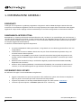 6
6
-
 7
7
-
 8
8
-
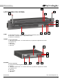 9
9
-
 10
10
-
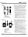 11
11
-
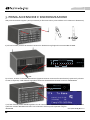 12
12
-
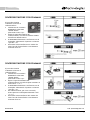 13
13
-
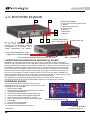 14
14
-
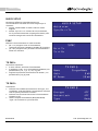 15
15
-
 16
16
-
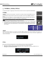 17
17
-
 18
18
-
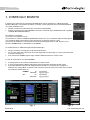 19
19
-
 20
20
-
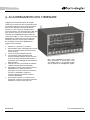 21
21
-
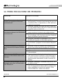 22
22
-
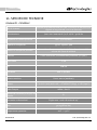 23
23
-
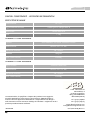 24
24
-
 25
25
-
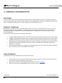 26
26
-
 27
27
-
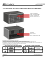 28
28
-
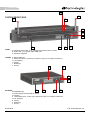 29
29
-
 30
30
-
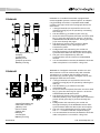 31
31
-
 32
32
-
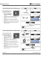 33
33
-
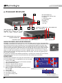 34
34
-
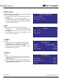 35
35
-
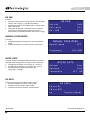 36
36
-
 37
37
-
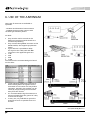 38
38
-
 39
39
-
 40
40
-
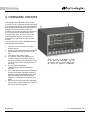 41
41
-
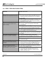 42
42
-
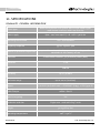 43
43
-
 44
44
-
 45
45
-
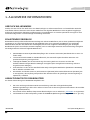 46
46
-
 47
47
-
 48
48
-
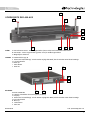 49
49
-
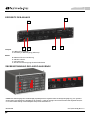 50
50
-
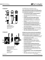 51
51
-
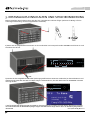 52
52
-
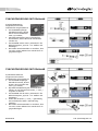 53
53
-
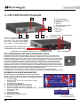 54
54
-
 55
55
-
 56
56
-
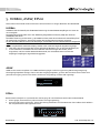 57
57
-
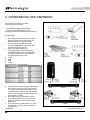 58
58
-
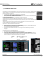 59
59
-
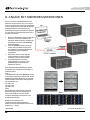 60
60
-
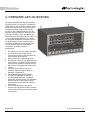 61
61
-
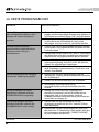 62
62
-
 63
63
-
 64
64
-
 65
65
-
 66
66
-
 67
67
-
 68
68
-
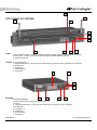 69
69
-
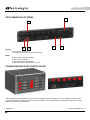 70
70
-
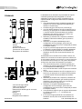 71
71
-
 72
72
-
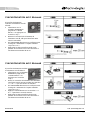 73
73
-
 74
74
-
 75
75
-
 76
76
-
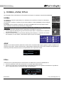 77
77
-
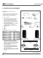 78
78
-
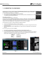 79
79
-
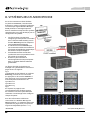 80
80
-
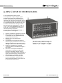 81
81
-
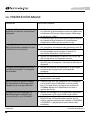 82
82
-
 83
83
-
 84
84
-
 85
85
-
 86
86
-
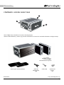 87
87
-
 88
88
-
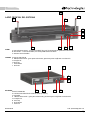 89
89
-
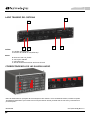 90
90
-
 91
91
-
 92
92
-
 93
93
-
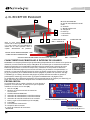 94
94
-
 95
95
-
 96
96
-
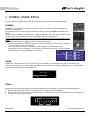 97
97
-
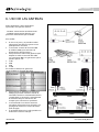 98
98
-
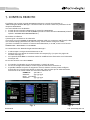 99
99
-
 100
100
-
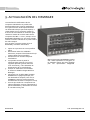 101
101
-
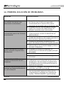 102
102
-
 103
103
-
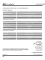 104
104


dBTechnologies RS16000 Touring Rack El manual del propietario
- Categoría
- Equipo de música suplementario
- Tipo
- El manual del propietario
en otros idiomas
Artículos relacionados
Otros documentos
-
Ferplast 57066070 Instrucciones de operación
-
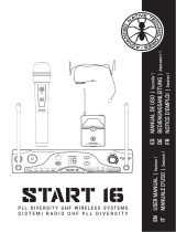 ADVANCED NATIVE TECHNOLOGIES Start 16 HDM Manual de usuario
-
Shure WA405 Manual de usuario
-
LD Systems WS 1000 MW Manual de usuario
-
LD Systems U506 CST Manual de usuario
-
-
Monacor TXS-900 Manual de usuario
-
Sennheiser EVOLUTION WIRELESS EW 100 El manual del propietario
-
IMG STAGELINE TXS-1820 Manual de usuario
-
