KNOVA KN BD-46L El manual del propietario
- Categoría
- Herramientas eléctricas
- Tipo
- El manual del propietario

KN BD-46L
Belt and disc sander
aluminum base
4
”
x6
”
(101.6 mm)
(914.4 mm)
Lijadora de banda y disco, base de aluminio
We invite you to read the user manual
before operating your equipment.
Lo invitamos a leer el manual del
usuario antes de operar su equipo.

Table of contents ......................................................... 1
Introduction ................................................................. 1
Product specications ................................................. 1
Warnings ..................................................................... 1
Symbols ....................................................................... 1
General safety rules .................................................... 2
Specic safety rules .................................................... 3
Electrical ...................................................................... 3
Know your belt/disc sander ........................................ 4
Assembly .................................................................... 5
Operation .................................................................... 7
Adjustments ................................................................ 10
Maintenance ............................................................... 11
Parts list ...................................................................... 12
Schematic view ........................................................... 13
PRODUCT SPECIFICATIONS
INTRODUCTION
TABLE OF CONTENTS
WARNINGS
The operation of any power tool can result in foreign objects being thrown into your eyes, which can
result in severe eye damage. Before beginning power tool operation, always wear safety goggles or safety glasses
with side shields and, when needed, a full face shield. We recommend Wide Vision Safety Mask for use over eyeglasses or
standard safety glasses with side shields. Always use eye protection which is marked to comply with ANSI Z87.1.
WARNING
SYMBOLS
The following signal words and meanings are intended
to explain the levels of risk associated with this product. Some of the following symbols may be used on
this tool. Please study them and learn their meaning.
Proper interpretation of these symbols will allow you
to operate the tool better and safer.
MOTOR
Motor: 4.5 Amp.
Input: 120 V. 60 Hz
BELT
Belt size:
4 in. x 36 in.
Belt speed: 8.8 mts./second
Belt table tilts: 0° ~ 90°
DISC
Disc diameter: 6 in.
Disc speed: 3,590 R.P.M.
TABLE
Table size: 8-7/8 in. x 6-1/4 in.
Table tilt: 0° ~ 45°.
Net weight: 25.35 lbs.
WARNING
To avoid serious
personal injury, do not attempt to
use this product until you read thoroughly
and understand completely the operator’s
manual. If you do not understand the
warnings and instructions in the operator’s
manual, do not use this product. Call Knova
customer service for assistance.
This tool has many features for making its use more pleasant and enjoyable. Safety, performance, and dependability have
been given top priority in the design of this product making it easy to maintain and operate.
1
DANGER:
WARNING:
CAUTION:
NOTICE:
Indicates an imminently hazardous
situation, which, if not avoided,
will result in death or serious injury.
Indicates a potentially hazardous
situation, which, if not avoided, could
result in death or serious injury.
Indicates a potentially hazardous
situation, which, if not avoided, may
result in minor or moderate injury.
(Without Safety Alert Symbol)
Indicates a situation that may
result in property damage.
MEANINGSYMBOL SIGNAL
Safety alert
Read
operator’s
manual
Eye
protection
Wet
conditions
alert
No hands
symbol
Indicates a potential personal
injury hazard.
To reduce the risk of injury, user must
read and understand operator’s manual
before using this product.
Always wear safety goggles
or safety glasses with side shields
and, as necessary, a full face shield
when operating this product.
Failure to keep your hands away
from the blade will result in serious
personal injury.
Do not expose to rain or use
in damp locations.
DESIGNATION/EXPLANATIONSYMBOL NAME
Some of the following symbols may be used on this tool. Please
study them and learn their meaning. Proper interpretation of these
symbols will allow you to operate the tool better and safer.
Volts
Amperes
Voltage
Current
DESIGNATION/EXPLANATIONSYMBOL NAME
V
A
Hertz
Hz Frequency (cycles per second)
Minutes
min Time
Alternating current Type of current
No Load Speed
noRotational speed, at no load
Per Minute
.../min
Revolutions, strokes, surface
speed, orbits etc., per minute

2
GENERAL SAFETY RULES
WARNING
Read and understand all instructions.
Failure to follow all instructions listed below, may result
in electric shock, re and/or serious personal injury.
READ ALL INSTRUCTIONS WORK AREA
• KNOW YOUR POWER TOOL. Read the operator’s
manual carefully. Learn the applications and limitations
as well as specic potential hazards related to this tool.
• GUARD AGAINST ELECTRICAL SHOCK BY
PREVENTING BODY CONTACT WITH GROUNDED
SURFACES. For example: pipes, radiators, ranges,
refrigerator enclosures.
• KEEP GUARDS IN PLACE and in working order.
• REMOVE ADJUSTING KEYS AND WRENCHES. Form
habit of checking to see keys and adjusting wrenches are
removed from tool before turning it on.
• KEEP THE WORK AREA CLEAN. Cluttered work areas
and work benches invite accidents. DO NOT leave tools
or pieces of wood on the tool while it is in operation.
• DO NOT USE IN DANGEROUS ENVIRONMENTS.
Do not use power tools in damp or wet locations
or expose them to rain. Keep the work area well lit.
• KEEP CHILDREN AND VISITORS AWAY. All visitors
should wear safety glasses and be kept a safe distance
from work area. Do not let visitors contact tool or
extension cord while operating.
• MAKE WORKSHOP CHILDPROOF with padlocks,
master switches, or by removing starter keys.
• DON’T FORCE THE TOOL. It will do the job better
and safer at the rate for which it was designed.
• USE THE RIGHT TOOL. Do not force the tool
or attachment to do a job for which it was not designed.
• USE THE PROPER EXTENSION CORD. Make sure your
extension cord is in good condition. Use only a cord heavy
enough to carry the current your product will draw. An
undersized cord will cause a drop in line voltage resulting
in loss of power and overheating. A wire gauge size
(A.W.G.) of at least 16 is recommended for an extension
cord 50 feet or less in length. If in doubt, use the next
heavier gauge. The smaller the gauge number, the heavier
the cord.
• DRESS PROPERLY. Do not wear loose clothing, neckties,
or jewelry that can get caught and draw you into moving
parts. Rubber gloves and nonslip footwear are
recommended when working outdoors. Also wear
protective hair covering to contain long hair.
• ALWAYS WEAR SAFETY GLASSES WITH SIDE
SHIELDS. Everyday eyeglasses have only impact-resistant
lenses, they are NOT safety glasses.
• SECURE WORK. Use clamps or a vise to hold work when
practical, it is safer than using your hand and frees both
hands to operate the tool.
• DO NOT OVERREACH. Keep proper footing
and balance at all times.
• MAINTAIN TOOLS WITH CARE. Keep tools sharp and
clean for best and safest performance. Follow instructions
for lubricating and changing accessories.
• DISCONNECT TOOLS. When not in use, before servicing,
or when changing attachments, blades, bits, cutters,
etc., All tools should be disconnected from power source.
• AVOID ACCIDENTAL STARTING. Be sure switch
is off when plugging in any tool.
• USE RECOMMENDED ACCESSORIES. Consult the
operator’s manual for recommended accessories. The
use of improper accessories may result in injury.
• NEVER STAND ON TOOL. Serious injury could occur if
the tool is tipped.
• CHECK DAMAGED PARTS. Before further use of the
tool, a guard or other part that is damaged should be
carefully checked to determine that it will operate properly
and perform its intended function. Check for alignment
of moving parts, binding of moving parts, breakage of
parts, mounting and any other conditions that may affect
its operation. A guard or other part that is damaged must
be properly repaired or replaced by an authorized service
center to avoid risk of personal injury.
• USE THE RIGHT DIRECTION OF FEED. Feed work into
a blade, cutter, or sanding spindle against the direction
or rotation of the blade, cutter, or sanding spindle only.
• NEVER LEAVE TOOL RUNNING UNATTENDED. TURN
THE POWER OFF. Don’t leave tool until it comes to a
complete stop.
• PROTECT YOUR LUNGS. Wear a face or dust mask if
the cutting operation is dusty.
• PROTECT YOUR HEARING. Wear hearing protection
during extended periods of operation.
• DO NOT ABUSE CORD. Never carry tool by the cord or
yank it to disconnect from receptacle. Keep cord from
heat, oil, and sharp edges.
• USE OUTDOOR EXTENSION CORDS. When tool
is used outdoors, use only extension cords with
approved ground connection that are intended for use
outdoors and so marked.
• KEEP BLADE CLEAN, SHARP AND WITH SUFFICIENT
SET. Sharp blades minimize stalling and kickback.
• NEVER USE IN AN EXPLOSIVE ATMOSPHERE.
Normal sparking of the motor could ignite fumes.
• INSPECT TOOL CORDS PERIODICALLY. If damaged,
have repaired by a qualied service technician at
an authorized service facility. The conductor with insulation
having an outer surface that is green with or without
yellow stripes is the equipment-grounding conductor. If
repair or replacement of the electric cord or plug is
necessary, do not connect the equipment-grounding
conductor to a live terminal. Repair or replace a
damaged or worn cord immediately. Stay constantly
aware of cord location and keep it well away from
the rotating blade.
• INSPECT EXTENSION CORDS PERIODICALLY
and replace if damaged.
• KEEP TOOL DRY, CLEAN, AND FREE FROM OIL AND
GREASE. Always use a clean cloth when cleaning. Never
use brake uids, gasoline, petroleum-based products, or
any solvents to clean tool.
• STAY ALERT AND EXERCISE CONTROL. Watch what
you are doing and use common sense. Do not operate
tool when you are tired. Do not rush.
• DO NOT USE TOOL IF SWITCH DOES NOT TURN IT
ON AND OFF. Have defective switches replaced by an
authorized service center.
• INSPECT FOR AND REMOVE ALL NAILS FROM
LUMBER BEFORE USING THIS TOOL. Following this rule
will reduce the risk of serious personal injury.

3
GENERAL SAFETY RULES
ELECTRICAL
EXTENSION CORDS
Use only 3-wire extension cords that have 3-prong grounding
plugs and 3-pole receptacles that accept the tool’s plug.
When using a power tool at a considerable distance from the
power source, use an extension cord heavy enough to carry
the current that the tool will draw. An undersized extension
cord will cause a drop in line voltage, resulting in a loss of
power and causing the motor to overheat. Use the chart
provided below to determine the minimum wire size required
in an extension cord. Only round jacketed cords listed by
Underwriter’s Laboratories (UL) should be used.
When working with the tool outdoors, use an extension cord
that is designed for outside use. This is indicated by the
letters “W-A” or “W” on the cord’s jacket.
Before using an extension cord, inspect it for loose or
exposed wires and cut or worn insulation.
WARNING
Keep the extension cord clear of the
working area. Position the cord so that it will not get
caught on lumber, tools or other obstructions while
you are working with a power tool. Failure to do so
can result in serious personal injury.
• NEVER START A TOOL WHEN ANY ROTATING
COMPONENT IS IN CONTACT WITH THE WORKPIECE.
• DO NOT OPERATE A TOOL WHILE UNDER THE
INFLUENCE OF DRUGS, ALCOHOL, OR ANY
MEDICATION.
• WHEN SERVICING use only identical replacement parts.
Use of any other parts may create a hazard or cause
product damage.
• FIRMLY CLAMP OR BOLT your tool to a workbench or
table at approximately hip height.
• NEVER stand or have any part of your body in line with
the path of the workpiece.
• PLAN YOUR WORK TO REDUCE THE RISK OF
THROWBACKS (when the workpiece catches the sanding
drum and is torn from your hands).
• MAKE SURE THERE’S NO DEBRIS between the
workpiece and its supports.
• WHEN SANDING IRREGULARLY SHAPES
WORKPIECES, plan your work support so it will not slip
and be pulled from your hands.
• USE EXTRA CAUTION WITH LARGE, very small or
awkward workpieces.
• NEVER USE THIS TOOL to nish pieces too small to
hold by hand.
• USE EXTRA SUPPORTS (TABLES, SAW HORSES,
BLOCKS, ETC.) for any workpieces large enough to tip
when not secured to the work surface.
• NEVER sand more than one piece at a time. DO NOT STACK
more than one workpiece on the sander table at a time.
• ALWAYS FEED WORKPIECE FROM LEFT TO RIGHT
against the direction the drum sleeve is rotating.
• DO NOT USE DRUMS, sanding sleeves or belts which
show visual signs of wear such as grooves, tears or rips.
• ALWAYS STAY ALERT! Do not allow familiarity (gained
from frequent use of your sander) to cause a careless
mistake. ALWAYS REMEMBER that a careless fraction
of a second is sufcient to inict severe injury.
• USE ONLY RECOMMENDED ACCESSORIES listed
in this manual or addendums. Use of accessories that
are not listed may cause the risk of personal injury.
Instructions for safe use of accessories are included
with the accessory.
• DOUBLE CHECK ALL SETUPS. Make sure the spindle
or sanding belt assembly is tight and not making contact
with sander or workpiece before connecting to
power supply.
SPECIFIC SAFETY RULES
• MAKE SURE THE WORK AREA HAS AMPLE LIGHTING
to see the work and that no obstructions will interfere with
safe operation BEFORE performing any work using your
tool.
• ALWAYS TURN OFF THE SANDER before disconnecting
it to avoid accidental starting when reconnecting to power
supply. NEVER leave the tool unattended while connected
to a power source.
• SUPPORT WORKPIECE with miter gauge, work rest, or
worktable.
• MAINTAIN 1/16 in. clearance between worktable and
sanding belt or disc.
• AVOID KICKBACK by sanding in accordance with
directional arrows.
• IF THE POWER SUPPLY CORD IS DAMAGED, it must
be replaced only by the manufacturer or by an authorized
service center to avoid risk.
• THIS TOOL should have the following markings:
a) Wear eye protection.
b) Support workpiece with miter gauge, backstop
(work support), or worktable.
c) Maintain 1/16 in. maximum clearance between
work table and sanding belt or disc.
d) Do not perform any operation freehand.
e) Avoid kickback by sanding in accordance with
directional arrows.
• SAVE THESE INSTRUCTIONS. Refer to them frequently
and use them to instruct others who may use this tool. If you
loan someone this tool, loan them these instructions also.
25’ 16 16 16 16 14 14
50’ 16 16 16 14 14 12
100’ 16 16 14 12 10 -
**Ampere rating (on tool data plate)
0-2.0 2.1-3.4 3.5-5.0 5.1-7.0 7.1-12.0 12.1-16.0
Cord Length Wire Size (A.W.G.)
**Used on 12 gauge - 20 amp circuit. NOTE: AWG = American Wire Gauge
WARNING
Check extension cords before each use.
If damaged replace immediately. Never use tool with
a damaged cord since touching the damaged area
could cause electrical shock resulting in serious injury.

4
ELECTRICAL
ELECTRICAL CONNECTION
This tool is powered by a precision-built electric motor. It should
be connected to a power supply that is 120 volts, 60 Hz, AC
only (normal household current). Do not operate this tool on
direct current (DC). A substantial voltage drop will cause a loss
of power and the motor will overheat. If the tool does not operate
when plugged into an outlet, double check the power supply.
SPEED AND WIRING
The belt speed of this tool is approximately 1,900 SFM. This
speed is not constant and decreases under a load or with lower
voltage. For voltage, the wiring in a shop is as important as the
motor’s horsepower rating. A line intended only for lights cannot
properly carry a power tool motor. Wire that is heavy enough for
a short distance will be too light for a greater distance. A line
that can support one power tool may not be able to support two
or three tools.
GROUNDING INSTRUCTIONS
In the event of a malfunction or breakdown, grounding provides a
path of least resistance for electric current to reduce the risk of
electric shock. This tool is equipped with an electric cord having
an equipment-grounding conductor and a grounding plug. The
plug must be plugged into a matching outlet that is properly
installed and grounded in accordance with all local codes and
ordinances.
Do not modify the plug provided. If it will not t the outlet, have
the proper outlet installed by a qualied electrician. Improper
connection of the equipment-grounding conductor can result in a
risk of electric shock. The conductor with insulation having an
outer surface that is green with or without yellow stripes is the
equipment-grounding conductor. If repair or replacement of the
electric cord or plug is necessary, do not connect the
equipment-grounding conductor to a live terminal.
Check with a qualied electrician or service personnel if the
grounding instructions are not completely understood, or if
in doubt as to whether the tool is properly grounded.
Repair or replace a
damaged or worn
cord immediately.
This tool is intended
for use on a circuit
that has an outlet like
the one shown in
gure 1. It also has
a grounding pin like
the one shown.
KNOW YOUR BELT/DISC SANDER
Fig. 1
Grounding
pin 120 V grounded outlet
The safe use of this product requires an understanding
of the information on the tool and in this operator’s
manual as well as a knowledge of the project you are
attempting. Beforeuse of this product, familiarize
yourself with all operating features and safety rules.
BELT TENSION LEVER The belt tension lever releases
the belt tension for easy belt replacement.
BEVEL SCALE The worktable comes equipped with a bevel
scale that indicates the degrees the worktable can be tilted
up to 45°.
MITER GAUGE The miter gauge aligns the wood for
positive stops at 90° and 45°.
POSITIONING BOLT Loosen the positioning bolt to
change sanding belt positions from horizontal to vertical.
Work
support Tracking
knob
Belt
tension
lever
Sanding
disc
Sanding belt
Positioning
bolt
Work
table
Miter gauge
Bevel
scale
Switch and
switch key
Fig. 2
SANDING BELT The sanding belt can be adjusted
from horizontal to vertical providing different positions for
sanding workpieces of different shapes and sizes.
SANDING DISC A round sanding disc is located on the side
of the belt/disc sander.
SWITCH AND SWITCH KEY Your belt/disc sander has an
easy access power switch.
TRACKING KNOB A tracking knob aids in centering the
sanding belt.
WORK SUPPORT (BACKSTOP) Supports
the workpiece on the sanding belt.
WORK TABLE Equipped with a sturdy work table that
provides a stable surface when using either the disc
sanding or the belt sanding feature.

5
ASSEMBLY
LOOSE PARTS LIST
The following items are included with the saw:
UNPACKING
This product requires assembly.
• Carefully lift sander from carton and place on a level work
surface.
• Inspect the tool carefully to make sure no breakage or
damage occurred during shipping.
• Do not discard the packing material until you have carefully
inspected and satisfactorily operated the product.
• The sander is factory set for accurate sanding. After
assembling it, check for accuracy. If shipping has inuenced
the settings, take to an authorized service center.
• If any parts are damaged or missing, please call
01-800-70-knova (56682), for assistance.
• Remove the backing from the sanding disc.
• Align perimeter of sanding disc with plate and press rmly
into position.
• Position disc guard against the lower one-third of the disc
aligning holes.
• Using the two phillips head screws, securely tighten the
disc guard in place.
WARNING
WARNING
WARNING
WARNING
Do not use this product if any parts on
the Loose Parts List are already assembled to your
product when you unpack it. Parts on this list are not
assembled to the product by the manufacturer and
require customer installation. Use of a product that
may have been improperly assembled could result in
serious personal injury.
If any parts are damaged or missing do
not operate this product until the parts are replaced.
Use of this product with damaged or missing parts
could result in serious personal injury.
Do not attempt to modify this product or
create accessories not recommended for use with this
tool. Any such alteration or modication is misuse and
could result in a hazardous condition leading to
possible serious personal injury.
Do not connect to power supply until
assembly is complete. Failure to comply could result
in accidental starting and possible serious personal
injury.
INSTALLING SANDING DISC AND DISC GUARD
Fig. 4
Work table
Miter
gauge
Sanding
disc
Socket head
screws
x 2
Disc
guard
Work
support
Washers
x 2
Sanding
disc
Disc
guard
Phillips
screws
Hex key
Table
lock knob
Washer
Phillips
screws
x 2
Fig. 3

6
ASSEMBLY
On the smooth side of the sanding belt, there is a directional
arrow. The sanding belt must run in the direction of the arrow.
• Using the hex key provided, loosen the positioning bolt
by turning the bolt counterclockwise.
• Move the sanding belt into a vertical position.
• Lock the sanding belt by retightening the positioning bolt.
• Pull the belt tension lever toward you to release the belt
tension.
• Place the sanding belt over the drive roller and idler roller
with the directional arrows running counterclockwise. Be
sure the sanding belt is centered on both drums.
• Push the belt tension lever back into place to apply the
belt tension.
NOTE: The belt tension lever is spring loaded; use extreme
caution when pushing the tension lever back into place to
avoid personal injury.
Fig. 7
Fig. 8
MOUNTING THE WORK TABLE FOR USE WITH
THE DISC SANDER
MOUNTING THE WORK TABLE FOR USE WITH
THE BELT SANDER
ASSEMBLING WORK SUPPORT
• Insert the work table index pin into the hole in the tool’s
housing.
• Position a washer over the table lock knob then tighten
the table lock knob securely.
• Insert the work table index pin into the hole in the sanding
belt arm.
• Position a washer over the table lock knob then tighten
the table lock knob securely.
• Place the work support over the holes in the side of the
sanding belt arm.
• Using a hex key, fasten in place with washers and socket
head screws.
C
INSTALLING/REPLACING SANDING BELT
Fig. 5
Drive roller
Sanding
belt Table
lock
knob
Socket
head
screws
Work
table
Washer
Work support
Washers
Index pin
Table
lock knob
Index pin Work table
Washer
Directional
arrow
Positioning
bolt
Idler roller
Belt
tension
lever
Fig. 6

ASSEMBLY
7
CLAMPING BELT/DISC SANDER TO WORKBENCH
Fig. 10
If the belt/disc sander is to be used as a portable tool, it is
recommended you fasten it permanently to a mounting board
that can easily be clamped to a workbench or other stable
surface. The mounting board should be of sufcient size to
avoid tipping while belt/disc sander is in use. Any good grade
plywood or chipboard with a 3/4 in. thickness is recommended.
• Mark holes on board where belt/disc sander is to be
mounted using holes in the base as a template for hole
pattern.
• Follow the last three steps in section Mounting Belt/Disc
Sander to Workbench.
If lag bolts are used, make sure they are long enough to go
through holes in belt/disc sander base and material the
belt/disc sander is being mounted to. If machine bolts are
used, make sure bolts are long enough to go through holes
in belt/disc sander, the material being mounted to, and the
lock washers and hex nuts.
APPLICATIONS
This product has been designed only for the purposes listed
below:
• Sanding and nishing plastic, wood, and wood composition
materials
• Bevel sanding
• Horizontal and vertical sanding
• Sanding curved pieces
OPERATION
WARNING
WARNING
WARNING
WARNING
Do not allow familiarity with tools to make
you careless. Remember that a careless fraction of a
second is sufcient to inict serious injury.
Always wear eye protection with side
shields marked to comply with ANSI Z87.1. Failure to
do so could result in objects being thrown into your
eyes, resulting in possible serious injury.
Do not use any attachments or
accessories not recommended by the manufacturer of
this tool. The use of attachments or accessories not
recommended can result in serious personal injury.
Applying the workpiece to the right side
of the sanding disc could cause the workpiece to
kickback and/or loss of control. Failure to heed this
warning could result in serious personal injury.
Fig. 9
MOUNTING BELT/DISC SANDER TO WORKBENCH
If the belt/disc sander is to be used in a permanent location,
it is recommended you secure it to a workbench or other
stable surface. When mounting the belt/disc sander to a
workbench, holes should be drilled through the supporting
surface of the workbench.
• Mark holes on workbench where belt/disc sander is to be
mounted using holes in the base as a template for hole
pattern.
• Drill holes through workbench.
• Place belt/disc sander on workbench aligning holes in
the base with holes drilled in the workbench.
• Insert bolts (not included) and tighten securely with lock
washers and hex nuts (not included).
Bolt
Bolt
Lock
washer
Hex
nut
Mounting
board
C-clamps
Hex
nut
Lock
washer

OPERATION
8
WARNING
Do not reach across the sanding disc to
turn the belt/disc sander ON or OFF. Contact with
the sanding disc can result in serious personal injury.
POWER SWITCH
The belt/disc sander is equipped with a power switch that
has a built-in locking feature. This feature is intended to
prevent unauthorized and possible hazardous use by children
and others.
TO TURN THE BELT/DISC SANDER ON:
• With the switch key inserted into the switch, lift the switch
button to turn ON.
TO TURN THE BELT/DISC SANDER OFF:
• Press the switch button down to turn OFF.
• Place the switch in the OFF position.
• Wait until the belt/disc sander has come to a full
and complete stop.
• Remove the switch key from the switch assembly. Store
key in safe place.
The worktable can be tilted from 0° to 45° for bevel sanding.
For angles 30º and above, position sander to the edge of the
work bench and mount sander in place as shown in gures 9
and 10.
To tilt the worktable:
• Loosen the table lock knob by turning it counterclockwise.
• Set worktable to desired angle.
• Tighten the table lock knob by turning it clockwise.
Switch
on
Switch
off
Switch key
removed
Fig. 11
WARNING
WARNING
WARNING
ALWAYS remove the switch key when the
tool is not in use and keep it in a safe place. In the
event of a power failure, turn the switch OFF and
remove the key. This action will prevent the tool from
accidentally starting when power returns.
ALWAYS make sure your workpiece is not
in contact with the belt before operating the switch to
start the tool. Failure to heed this warning may cause
the workpiece to be kicked back toward the operator
and result in serious personal injury.
To reduce the risk of accidental starting,
ALWAYS make sure the switch is in the OFF position
before plugging tool into the power source..
LOCKING THE SWITCH
“No Hands”
label
Switch key
Fig. 12
BEVEL SANDING
Table lock knob
Fig. 13
Fig. 14

9
OPERATION
SANDING SMALL END SURFACES USING
THE MITER GAUGE
HORIZONTAL AND VERTICAL SANDING
SURFACE SANDING ON THE SANDING BELT
A miter gauge is included with the tool for increased accuracy.
Use of a miter gauge is recommended for sanding small end
surfaces on the sanding disc.
NOTE: Always move the workpiece
across the sanding disc from the
left side toward the center.
The belt/disc sander can sand both vertically and
horizontally. Depending on the workpiece, use the work
support for horizontal sanding operations and use the work
table for vertical sanding operations.
• Using the hex key provided, loosen the positioning bolt
by turning the bolt counterclockwise.
• Move the sanding belt into a vertical position.
• Lock the sanding belt by retightening the positioning bolt.
Fig. 15
Fig. 16
Fig. 15 b
Miter gauge
Miter gauge
Directional
arrows
Vertical
position
Horizontal
position
Positioning
bolt
Directional
arrows
WARNING
ALWAYS use the work support for
horizontal sanding and use the work table for vertical
sanding. Using the sander without also using the work
support or work table may expose the operator to
pinch points and could result in serious personal injury.
NOTE: Sand long workpieces
with the sanding belt in the
vertical position by moving
the work evenly across
the sanding belt.
Fig. 17
Work
support
Workpiece

OPERATION
• Hold the workpiece rmly, keeping ngers away from
the sanding belt.
• Keep the end pressed rmly against the work support
moving work evenly across the sanding belt.
NOTE: Use extra caution when sanding very thin pieces.
When sanding extra long pieces, move the work piece across
the belt while applying only enough pressure to allow the
sanding belt to remove the material.
Sanding inside curves on the sanding belt:
Always sand inside curves on the idler drum.
• Hold the workpiece rmly, keeping ngers away from
the sanding belt.
• Keep the curve pressed rmly against the idler drum
moving work evenly across the sanding belt.
NOTE: Use extra caution when sanding
very thin pieces and apply only enough
pressure to allow the sanding
belt to remove the material.
Sanding outside
curves on the
sanding disc:
Always sand outside curves using
the sanding disc and moving the workpiece
from the left side of center.
• Hold the workpiece rmly, keeping ngers
away from the sanding disc.
• Keep the curve pressed rmly against the sanding disc
moving work evenly on the left side of the sanding disc.
NOTE: Always move the workpiece across the sanding disc
from the left side toward the center.
• Plug in belt/disc sander.
To check belt tracking:
• Turn the switch ON and then immediately turn it OFF.
If the belt tends to slide off the idler drum or drive drum,
the belt is not tracking properly.
To adjust belt tracking:
• If the sanding belt moves toward the disc, turn
the tracking knob up 1/4 turn.
• If the sanding belt moves away from the disc,
turn the tracking knob down 1/4 turn.
• Turn the switch ON and then immediately OFF
again, noting belt movement. Readjust tracking
knob if necessary.
SANDING CURVED PIECES
Belt direction
towards work
support
Workpiece
Idler roller
Workpiece
Fig. 18
WARNING
Never attempt to sand the end pieces of
a workpiece on the idler drum. Applying the end of the
workpiece on the idler drum could cause the
workpiece to y up. Failure to heed this warning could
result in serious personal injury.
Fig. 19
ADJUSTMENTS
WARNING
ADJUSTING THE BELT TRACKING
Switch
Tracking
knob
Before performing any adjustment, make
sure the tool is unplugged from the power supply and
the switch is in the OFF ( O ) position. Failure to heed
this warning could result in serious personal injury.
10
Fig. 20

11
ADJUSTMENTS
• Unplug the belt/disc sander.
• Using a combination square, check the angle of the
worktable with the sanding belt.
• If the work table is not 90° with the disc, loosen the table
lock knob and tilt the table.
• Adjust work table square to the sanding disc and retighten
the table lock knob.
Avoid using solvents when cleaning plastic parts. Most
plastics are susceptible to damage from various types of
commercial solvents and may be damaged by their use. Use
clean cloths to remove dirt, dust, oil, grease, etc.
All of the bearings in this tool are lubricated with a sufcient
amount of high grade lubricant for the life of the unit under
normal operating conditions. Therefore, no further lubrication
is required.
• Unplug the belt/disc sander.
• Using a phillips head screwdriver, remove the screw
in the center of the belt cover.
• Remove the cover.
SQUARING THE WORKTABLE TO THE SANDING DISC
GENERAL MAINTENANCE
LUBRICATION
CHANGING DRIVE BELT
Combination
square
Table
lock knob
Drive
pulley
Pulley
housing Tension
screw
Phillips
screw Belt
cover
Drive
belt
Motor
pulley
Fig. 21
Fig. 22
MAINTENANCE
WARNING
WARNING
WARNING
WARNING
When servicing, use only identical
replacement parts. Use of any other parts may create
a hazard or cause product damage.
Always wear eye protection with side
shields marked to comply with ANSI Z87.1 during
product operation. If operation is dusty, also wear a
dust mask.
Before performing any maintenance, make
sure the tool is unplugged from the power supply and
the switch is in the off ( O ) position. Failure to heed
this warning could result in serious personal injury.
Do not at any time let brake uids,
gasoline, petroleumbased products, penetrating oils,
etc., come in contact with plastic parts. Chemicals can
damage, weaken or destroy plastic which may result
in serious personal injury.
• Loosen the three tension screws inside the pulley housing
then push the housing down
to loosen the belt
tension.
• Remove the old
drive belt.
• Fit the new drive
belt on the drive
pulley rst then
on the motor
pulley.
• Test belt tension by
squeezing the belt
with your ngers.
• Push the pulley
housing up to
increase belt
tension until there
is about 1/4 inch
of give.
• Tighten the tension
screws securely.
• Using a phillips
head screwdriver,
reinstall the
pulley cover
and the screw.
Tighten
securely

1 Philips screw assembly M4 x 6 5
2 Base plate 1
3 Philips screw assembly M4 x 7 3
4 Tooth lock washer Ø4 3
5 Philips screw ST4.2 x 10 2
6 Sanding disc cover 1
7 Sanding disc paper
150mm-80#
1
8
Inner hex screw+tooth lock washer assembly
M6 x 16 1
9 Sanding disc plate 1
10 Disc guard 1
11 Switch plate 1
12 Philips pan screw M5 x 8 5
13 Philips screw and spring washer assembly M5 x 25 3
14 Belt tension lever 1
15 Bushing 1
16 Philips screw assembly M5 x 16 1
17 Base 1
18 Work table lock knob 1
19 Hex nut M8 M8 2
20 Hex nut M6 M6 4
21 Philips screw M4 x 20 2
22 Spring 1
23 Cotter pin 1.6 x 10 1
24 Pin 5 x 10 1
25 Philips screw assembly M5 x 8 1
26 Philips screw M4 x 10 3
27 Right work table bafe 1
28 Left work table bafe 1
29 Philips screw 3.5 x 9.5 4
30 Hex nut M6 3
31 Hex bolt M6 x 14 3
32 Big washer Ø6 3
33 Work table support 1
34 Miter gauge knob 1
35 Work table 1
36 Miter gauge bar 1
37 Miter gauge pointer 1
38 Miter gauge 1
39 Switch HY7 1
40 Tension spring 1
41 Bushing 2
42 Belt tension support 1
43 Retaining ring D12 2
44 Bearing 6001-2RS 4
PARTS LIST
12
Description Qty.
I.D. No. Size Description Qty.
I.D. No. Size
45 Idler drum 1
46 Idler shaft 1
47 Philips pan screw M5 x 25 2
48 Capacitor support 1
49 Capacitor 40uF/300V 1
50 Hex bolt and spring washer M6 x 20 3
51 Belt
100 x 914 mm
1
52 Inner hex screw and at washer M8 x 16 2
53 Belt frame support 1
54 Philips screw M5 x 16 1
55 Bearing base 1
56 Belt tracking knob 1
57 Rubber washer 1
58 Belt tracking spring 1
59 Belt support 1
60 Work stop 1
61 Driving drum assy 1
62 Power cord 1
63 Inner hex wrench
M6 x 90 x 32
1
64 Bearing cap 1
65 Support cover 1
66 Philips screw M5 x 12 1
67 Belt cover 1
68 Philips screw assembly
M5 x 16 left
2
69 Motor shaft wheel 1
70 Belt 1
71 Driven pulley 1
72
Philips pan screw+spring washer+at washer assembly
M6 x 25 3
73 Inner hex bolt M8 x 25 1
74 Belt cover 1
75 Washer D17 1
76 Strain relief 6P4 1
77 Strain relief subplate 1
78 Strain relief plate 1
79 Philips screw M5 x 20 2
80 Dust port 1
81 Front end bell 1
82 Philips pan screw M6 x 113 4
83 Guard ring 1
84 Bearing 6003-2RS 2
85 Stator 1
86 Rotor 1
87 Wave washer Ø35 1
88 Back end bell 1

Belt and disc sander
aluminum base
4
”
x6
”
(101.6 mm)
(914.4 mm)
Lijadora de banda y disco base de aluminio
KN BD-46L
SCHEMATIC VIEW
13

Para evitar
lesiones corporales serias, no
intente utilizar este producto sin haber leí-
do y comprendido totalmente el manual del
operador. Si no comprende los avisos de
advertencia y las instrucciones del manual
del operador, no utilice este producto.
Llame al departamento de atención al
consumidor de Knova, y le brindaremos
asistencia.
INDICE DE CONTENIDO
14
Indice de contenido .................................................. 14
Introducción ............................................................. 14
Especicaciones del producto .................................. 14
Advertencias ............................................................ 14
Símbolos .................................................................. 14
Reglas de seguridad generales ................................ 15
Reglas de seguridad especícas .............................. 16
Aspectos eléctricos .................................................. 17
Conozca su lijadora de banda y disco ........................ 18
Armado ...................................................................... 18
Funcionamiento ......................................................... 21
Ajustes ...................................................................... 24
Mantenimiento ........................................................... 25
Lista de partes ........................................................... 26
Vista esquemática ..................................................... 27
ESPECIFICACIONES DEL PRODUCTO
INTRODUCCIÓN
ADVERTENCIAS
SÍMBOLOS
MOTOR
Motor: 4.3 Amp.
Potencia nominal:
120 V., 60 Hz.
BANDA
Tam. de la banda:
101.6 x 914.4 mm (4 x 36 pulg.)
Vel. de la banda:
8.8 mts./segundo
Incli. de la banda:
0° ~ 90°.
DISCO
Tam. del disco: 152.4 mm (6 pulg.)
Vel. del disco: 3,590 R.P.M.
MESA
Tam. de la mesa:
225.4 x 158.75 mm (8-7/8 x 6-1/4 pulg.)
Incli. de la mesa: 0° ~ 45°.
Peso neto: 11.5 kgs.
ADVERTENCIA
Esta herramienta ofrece numerosas características para hacer más agradable y placentero su uso. En el diseño de este producto se
ha conferido prioridad a la seguridad, el desempeño y la abilidad, por lo cual se facilita su manejo y mantenimiento.
Cualquier herramienta eléctrica en funcionamiento puede lanzar objetos hacia los ojos, lo cual puede
causar serios daños a los mismos. Antes de iniciar la operación de herramientas de corriente siempre utilice gafas de
seguridad, gafas de seguridad con protección lateral, y en la medida en que sea necesario, un protector para toda la cara.
Recomendamos la careta protectora de visión amplia encima de los anteojos normales, o los anteojos protectores estándar con
protección lateral. Siempre póngase protección ocular con la marca de cumplimiento de la norma ANSI Z87.1.
ADVERTENCIA
Las siguientes palabras de señalización y sus signicados tienen el
objeto de explicar los niveles de riesgo relacionados con este producto.
Es posible que se empleen en este producto algunos de los
siguientes símbolos. Le suplicamos estudiarlos y aprender su
signicado. Una correcta interpretación de estos símbolos le
permitirá utilizar mejor y de manera más segura el producto.
PELIGRO:
ADVERTENCIA:
PRECAUCIÓN:
AVISO:
Indica una situación peligrosa
inminente, la cual, si no se evita,
causará la muerte o lesiones serias.
Indica una situación peligrosa
posible, la cual, si no se evita, podría
causar la muerte o lesiones serias.
Indica una situación potencialmente
peligrosa la cual, si no se evita, puede
causar lesiones leves o moderadas.
(Sin el símbolo de alerta de
seguridad) Indica una situación que
puede producir daños materiales.
SIGNIFICADOSÍMBOLO SEÑAL
Alerta de
seguridad
Lea
el manual
del operador
Protección
ocular
Alerta de
condiciones
húmedas
Símbolo de
no acercar
las manos
Indica un peligro posible de lesiones
personales.
Para reducir el riesgo de lesiones, el
usuario debe leer y comprender el manual
del operador antes de usar este producto.
Siempre lleve las gafas de la seguridad o
gafas de seguridad con protectores de
lado y, como sea necesario, un protector
repleto de la cara al operar este producto.
Si no mantiene las manos alejadas de
la hoja de corte, se causará serias
lesiones corporales.
No exponga la unidad a la lluvia ni la use
en lugares húmedos.
DENOMINACIÓN/EXPLICACIÓNSIMBOLO NOMBRE
Es posible que se empleen en este producto algunos de los siguientes símbolos.
Le suplicamos estudiarlos y aprender su signicado. Una correcta interpretación
de estos símbolos le permitirá utilizar mejor y de manera más segura el producto.
Volts
Amperes
Voltaje
Corriente
DENOMINACIÓN/EXPLICACIÓNSÍMBOLO NOMBRE
V
A
Hertz
Hz Frecuencia (ciclos por segundo)
Minutos
min Tiempo
Corriente alterna Tipo de corriente
Velocidad en vacío
noVelocidad de rotación, en vacío
Por minuto
.../min
Revoluciones, carreras, velocidad
supercial, órbitas, etc., por minuto

REGLAS DE SEGURIDAD GENERALES
15
LEA TODAS LAS INSTRUCCIONES TRABAJE ÁREA
• FAMILIARÍCESE CON SU HERRAMIENTA ELÉCTRICA.
Lea cuidadosamente el manual del operador. Aprenda los
usos, limitaciones y posibles peligros relacionados con esta
herramienta.
• PROTÉJASE CONTRA DESCARGAS ELÉCTRICAS
EVITANDO TOCAR CON EL CUERPO SUPERFICIES
CONECTADAS A TIERRA. Por ejemplo: tubos, radiadores,
estufas y cajas de refrigeradores.
• MANTENGA LAS PROTECCIONES EN SU LUGAR
y en buenas condiciones de trabajo.
• RETIRE TODA LLAVE Y HERRAMIENTA DE AJUSTE.
Adquiera el hábito de vericar que se haya retirado de la
herramienta eléctrica toda llave y herramienta de ajuste
antes de encenderla.
• MANTENGA LIMPIA EL ÁREA DE TRABAJO. Las áreas y
mesas de trabajo mal despejadas son causas comunes de
accidentes. NO deje herramientas o piezas de madera en la
herramienta mientras esté funcionando.
• NO UTILICE LA HERRAMIENTA EN ENTORNOS
PELIGROSOS. No utilice las herramientas eléctricas en
lugares húmedos o mojados ni las exponga a la lluvia.
Mantenga bien iluminada el área de trabajo.
• MANTENGA ALEJADOS A LOS NIÑOS Y DEMÁS
CIRCUNSTANTES. Todos los presentes deben llevar
puestos anteojos de seguridad y permanecer a una
distancia segura del área de trabajo. No permita que
ninguno de los presentes toque la herramienta eléctrica o el
cordón de extensión mientras esté funcionando la unidad.
• HAGA SU TALLER A PRUEBA DE NIÑOS con candados,
interruptores maestros y retirando las llaves de arranque.
• NO FUERCE LA HERRAMIENTA. Efectúa el trabajo mejor
y de manera más segura, si se utiliza a la velocidad para la
que está diseñada.
• USE LA HERRAMIENTA ADECUADA PARA LA TAREA.
No fuerce la herramienta ni ningún accesorio a efectuar
tareas para las que no están hechos.
• USE UN CORDÓN DE EXTENSIÓN ADECUADO.
Asegúrese de que esté en buen estado el cordón de
extensión. Al utilizar un cordón de extensión sólo utilice uno
del calibre suciente para soportar la corriente que consume
el producto. Un cordón de un grueso insuciente causa una
caída en el voltaje de línea, y produce recalentamiento y
pérdida de potencia. Se recomienda que los conductores
sean de calibre 16 (A.W.G.) por lo menos, para un cordón
de extensión de 50 pies (7,6 metros) de largo o menos. Si
tiene dudas, utilice un cordón del calibre más grueso
siguiente. Cuanto menor es el número de calibre, mayor
es el grueso del cordón.
• VÍSTASE ADECUADAMENTE. Evite ponerse ropas
holgadas, corbatas ni joyas que puedan engancharse y
tirar de usted hacia las piezas en movimiento. Se
recomiendan guantes y calzado antiderrapantes al trabajar
al aire libre. Si tiene el pelo largo cúbraselo de alguna
manera para contenerlo.
• SIEMPRE PÓNGASE ANTEOJOS DE SEGURIDAD CON
PROTECCIÓN LATERAL. Los anteojos de uso diario tienen
lentes resistentes a golpes únicamente; NO son anteojos
de seguridad.
• ASEGURE LA PIEZA DE TRABAJO. Utilice prensas de
mano o de banco para sujetar la pieza de trabajo cuando
resulte práctico hacerlo; es más seguro que utilizar la mano
y quedan ambas manos libres para manejar la herramienta.
• NO ESTIRE EL CUERPO PARA ALCANZAR MAYOR
DISTANCIA. Mantenga una postura rme y buen
equilibrio en todo momento.
• DE MANTENIMIENTO CON CUIDADO A LAS
HERRAMIENTAS. Mantenga aladas y limpias las
herramientas para obtener de las mismas un desempeño
mejor y más seguro. Siga las instrucciones
correspondientes al cambio y lubricación de accesorios.
• DESCONECTE LAS HERRAMIENTAS. Todas las
herramientas deben desconectarse del suministro de
corriente cuando no estén usándose, o al cambiarles
aditamentos, hojas de corte, brocas, fresas, etc.
• EVITE UN ARRANQUE ACCIDENTAL DE LA UNIDAD.
Asegúrese de que el interruptor esté en la posición de
apagado antes de conectar la clavija de cualquier
herramienta.
• USE ACCESORIOS RECOMENDADOS. Consulte este
manual del operador, donde aparecen los accesorios
recomendados. El empleo de accesorios inadecuados
puede causar lesiones.
• NO SE PARE NUNCA EN LA HERRAMIENTA. Pueden
producirse lesiones serias si se vuelca la herramienta.
• INSPECCIONE LAS PIEZAS DAÑADAS. Antes de seguir
utilizando la herramienta, es necesario inspeccionar
cuidadosamente toda protección o pieza dañada para
determinar si funcionará correctamente y desempeñará la
función a la que está destinada. Verique la alineación de
las partes móviles, que no haya atoramiento de partes
móviles, que no haya piezas rotas, el montaje de las piezas
y cualquier otra condición que pudiera afectar su
funcionamiento. Toda protección o pieza que esté dañada
debe repararse apropiadamente o reemplazarse en un
centro de servicio autorizado.
• AVANCE LA PIEZA DE TRABAJO EN LA DIRECCIÓN
CORRECTA. Solamente empuje la pieza de trabajo hacia
la hoja, fresa o tambor de lijado, contra el sentido de
rotación de éstos.
• NUNCA DEJE FUNCIONANDO DESATENDIDA LA
HERRAMIENTA. APAGUE LA CORRIENTE. No abandone
la herramienta hasta verla completamente detenida.
• PROTÉJASE LOS PULMONES. Use una careta o
mascarilla contra el polvo si la operación de corte genera
mucho polvo.
• PROTÉJASE EL OÍDO. Durante períodos prolongados de
utilización de la unidad póngase protección para los oídos.
• NO MALTRATE EL CORDÓN ELÉCTRICO. Nunca porte
la herramienta sujetándola por el cordón eléctrico, ni tire
del mismo para desconectarla de la toma de corriente.
Mantenga el cordón eléctrico alejado del calor, del aceite
y de los bordes alados.
• UTILICE CORDONES DE EXTENSIÓN PARA USO
EN EL EXTERIOR. Al utilizar la herramienta en el exterior,
sólo utilice cordones de extensión con conexión a tierra
aprobada apropiados para uso al aire libre y marcados para
tal tipo de uso.
• MANTENGA LAS HOJAS DE CORTE LIMPIAS Y
AFILADAS. Las hojas de corte aladas reducen al mínimo
los paros y los contragolpes.
• NUNCA UTILICE EN UNA ATMÓSFERA EXPLOSIVA.
Chispear normal del motor podría encender vapores.
Lea y comprenda todas las
instrucciones. El incumplimiento de las instrucciones
señaladas abajo puede causar descargas eléctricas,
incendios y lesiones serias.
ADVERTENCIA

REGLAS DE SEGURIDAD GENERALES
16
• INSPECCIONE PERIÓDICAMENTE LOS CORDONES
ELÉCTRICOS DE LAS HERRAMIENTAS. Si están
dañados, llévelos a un establecimiento de servicio
autorizado para que los revise un técnico de servicio
calicado. El conductor con aislamiento que tiene una
supercie exterior verde con o sin tiras amarillas es el
conductor de conexión a tierra del equipo. Si es necesaria la
reparación o reemplazo del cordón eléctrico o de la clavija,
no conecte el conductor de conexión a tierra a una terminal
portadora de corriente. Repare o reemplace de inmediato
todo cordón dañado o gastado. Siempre esté consciente de
la ubicación del cordón y manténgalo bien alejado de la hoja
en movimiento de giro.
• NUNCA UTILICE LA UNIDAD EN UNA ATMÓSFERA
EXPLOSIVA. El chispeo normal del motor podría encender
los gases presentes.
• INSPECCIONE PERIÓDICAMENTE LOS CORDONES
DE EXTENSIÓN y reemplácelos si están dañados.
• MANTENGA LA HERRAMIENTA SECA, LIMPIA Y LIBRE
DE ACEITE Y GRASA. Siempre utilice un paño limpio para
la limpieza de la unidad. Nunca utilice uidos para frenos,
gasolina, productos a base de petróleo ni solventes para
limpiar la herramienta.
• PERMANEZCA ALERTA Y EN CONTROL. Preste
atención a lo que esté haciendo y aplique el sentido común.
No utilice la herramienta cuando esté cansado. No se
apresure.
•
NO UTILICE LA HERRAMIENTA SI EL INTERRUPTOR NO
ENCIENDE O NO APAGA. Lleve todo interruptor defectuoso
a un centro de servicio autorizado para que lo reparen.
• INSPECCIONE LA MADERA Y ELIMINE TODOS LOS
CLAVOS PRESENTES EN LA MISMA ANTES DE
USAR ESTA HERRAMIENTA. Con el cumplimiento de esta
regla se reduce el riesgo de lesiones serias.
• NUNCA ARRANQUE LA HERRAMIENTA CUANDO
LA PIEZA GIRATORIA CORRESPONDIENTE
ESTE TOCANDO LA PIEZA DE TRABAJO.
• NO UTILICE NINGUNA HERRAMIENTA SI SE
ENCUENTRA BAJO LOS EFECTOS DE DROGAS,
ALCOHOL O MEDICAMENTOS.
• AL DAR SERVICIO a la unidad, sólo utilice piezas de
repuesto idénticas. El empleo de piezas diferentes puede
causar un peligro o dañar el producto.
• SOLAMENTE UTILICE ACCESORIOS señalados en este
manual o en los apéndices. El uso de accesorios no
señalados en este manual puede presentar riesgos de
lesiones corporales. Con los accesorios se incluyen
instrucciones para el uso seguro de los mismos.
• REVISE DOS VECES TODA CONFIGURACIÓN DE LA
HERRAMIENTA. Asegúrese de que el tambor o el conjunto
de la banda de lijado esté apretado y de que no toque la
lijadora o la pieza de trabajo antes de conectar la unidad al
suministro de corriente.
REGLAS DE SEGURIDAD ESPECIFICAS
• SUJETE FIRMEMENTE CON PRENSAS DE MANO O
PERNOS la herramienta en una mesa o banco de trabajo
aproximadamente a la altura de la cadera.
• NUNCA se pare ni tenga ninguna parte del cuerpo
en línea con la trayectoria de la pieza de trabajo.
• PLANIFIQUE EL TRABAJO CON EL FIN DE DISMINUIR
EL RIESGO DE CAUSAR CONTRAGOLPES (cuando la
pieza de trabajo se pega al tambor de lijado y éste se la
arrebata de las manos).
• ASEGÚRESE DE QUE NO HAYA DESECHOS entre la
pieza de trabajo y los soportes de la misma.
• AL LIJAR UNA PIEZA DE FORMA IRREGULAR,
planique el soporte de la misma de manera que se
le resbale y la máquina se la arrebate de las manos.
• TENGA PRECAUCIÓN EXTREMA AL trabajar con
piezas largas, muy pequeñas o de forma inusual.
• NUNCA UTILICE ESTA HERRAMIENTA para acabar
piezas demasiado pequeñas como para poder sujetarlas
con las manos.
• USE SOPORTES EXTRA (MESAS, BURROS, BLOQUES,
ETC.) al trabajar con piezas lo sucientemente largas como
para inclinarse si no está asegurada en la supercie
de trabajo.
• NUNCA lije más de una pieza a la vez. NO APILE más de
una pieza de trabajo sobre la mesa de la lijadora a la vez.
• SIEMPRE AVANCE LA PIEZA DE TRABAJO DE
IZQUIERDA A DERECHA, contra la dirección en que está
girando el tubo de lija.
• NO UTILICE TAMBORES, ni tubos o bandas de lija que
muestren señales de desgaste como ranuras, desgarres
o rasgones.
• ¡SIEMPRE PERMANEZCA ALERTA! No permita que su
familiaridad con la máquina (proveniente del uso
frecuente de la lijadora) sea causa de un error de descuido.
SIEMPRE TENGA PRESENTE que un descuido de un
instante es suciente para causar una lesión grave.
• ASEGÚRESE DE QUE EL ÁREA DE TRABAJO CUENTE
CON SUFICIENTE ILUMINACIÓN para ver la pieza de
trabajo y de que ninguna obstrucción interera en la
seguridad de la operación ANTES de efectuar
cualquier trabajo en la herramienta.
• SIEMPRE APAGUE LA LIJADORA antes de desconectarla
para evitar un arranque accidental de la misma al volver a
conectarla al suministro de corriente. NUNCA deje
desatendida la herramienta mientras esté conectada
a un suministro de corriente.
• APOYE LA PIEZA DE TRABAJO en una guía de ingletes,
apoyo o mesa de trabajo.
• MANTENGA UN ESPACIO DE 1.5 mm (1/16 pulg.) entre
la mesa de trabajo y la banda o tubo de lija.
• EVITE TODO CONTRAGOLPE lijando según indican
las echas direccionales.
• SI ESTA DAÑADO EL CORDÓN DE CORRIENTE, debe
ser reemplazado únicamente por el fabricante o en un
centro de servicio autorizado para evitar riesgos.
• ESTA HERRAMIENTA tendrá los siguientes avisos:
a) Póngase protección ocular.
b) Apoye la pieza de trabajo en una guía de ingletes,
la mampara (soporte de la pieza de trabajo)
o mesa de trabajo.
c) Mantenga un espacio de 1.5 mm (1/16 pulg.)
entre la mesa de trabajo y la banda o disco de lija.
d) No efectúe a pulso ninguna operación.
e) Evite todo contragolpe lijando según indican
las echas direccionales.
• GUARDE ESTAS INSTRUCCIONES. Consúltelas con
frecuencia y empléelas para instruir a otras personas que
puedan utilizar esta herramienta. Si presta a alguien
esta herramienta, facilítele también las instrucciones.

Patilla de
conexión a tierra Toma de corriente con
tierra, de 120 V)
Fig. 1
ASPECTOS ELÉCTRICOS
17
CORDONES DE EXTENSIÓN
Sólo utilice cordones de extensión de 3 conductores con
clavijas de tres patillas y receptáculos de tres polos que
acepten la clavija del cordón de la herramienta. Al utilizar
una herramienta eléctrica a una distancia considerable
del suministro de corriente, asegúrese de utilizar un cordón
de extensión del grueso suciente para soportar el consumo
de corriente de la herramienta. Un cordón de extensión de un
grueso insuciente causa una caída en el voltaje de línea,
además de producir una pérdida de potencia y un
recalentamiento del motor. Básese en la tabla suministrada
abajo para determinar el calibre mínimo requerido de los
conductores del cordón de extensión. Solamente deben
utilizarse cordones con forro redondo registrados en
Underwriter’s Laboratories (UL).
Al trabajar a la intemperie con la herramienta, utilice un cor-
dón de extensión fabricado para uso en el exterior. Tal
característica está indicada con las letras “WA” en el forro
del cordón.
Antes de utilizar un cordón de extensión, inspecciónelo para
ver si tiene conductores ojos o expuestos y aislamiento
cortado o gastado.
CONEXIÓN ELÉCTRICA
Esta herramienta está impulsada por un motor eléctrico
fabricado con precisión. Debe conectarse únicamente a
una línea de voltaje de 120 voltios, 60 Hz, de corriente
alterna solamente (corriente normal para uso doméstico).
No utilice esta herramienta con corriente continua (c.c.).
Una caída considerable de voltaje causa la pérdida de
potencia y el recalentamiento del motor. Si la sierra no
funciona al conectarla en una toma de corriente, vuelva a
revisar el suministro de corriente.
En caso de un mal funcionamiento o desperfecto, la conexión
a tierra brinda a la corriente eléctrica una trayectoria de
mínima resistencia para disminuir el riesgo de una descarga
eléctrica. Esta herramienta está equipada de un cordón
eléctrico con un conductor y una clavija de conexión a tierra
para equipo. La clavija debe conectarse en una toma de
corriente igual que esté instalada y conectada a tierra
correctamente, de conformidad con los códigos y
reglamentos de la localidad.
No modique la clavija suministrada. Si no entra en la toma de
corriente, llame a un electricista calicado para que instale
una toma de corriente adecuada. Si se conecta de forma
incorrecta el conductor de conexión a tierra del equipo puede
presentarse un riesgo de descarga eléctrica. El conductor con
aislamiento que tiene una supercie exterior verde con o sin
tiras amarillas es el conductor de conexión a tierra del equipo.
Si es necesaria la reparación o reemplazo del cordón eléctrico
o de la clavija, no conecte el conductor de conexión a tierra a
una terminal portadora de corriente.
Consulte a un electricista calicado o técnico de servicio si no
ha comprendido completamente las instrucciones de conexión
a tierra o si no está seguro si la herramienta está bien
conectada a tierra.
Repare o reemplace de inmediato todo cordón dañado o
gastado. Esta herramienta debe utilizarse conectada a un
circuito con una toma de corriente como la mostrada en
la gura 1. También dispone de una patilla de conexión a
tierra como la mostrada.
7.6 mts. 16 16 16 16 14 14
15.2 mts.
16 16 16 14 14 12
30.5 mts.
16 16 14 12 10 -
**Amperaje (aparece en la placa frontal)
0-2.0 2.1-3.4 3.5-5.0 5.1-7.0 7.1-12.0 12.1-16.0
Longitud
del cordón: Calibre conductores
(A.W.G.)
**Se usa en los circuitos de calibre 12, 20 amp.
NOTA: AWG = Calibre conductores norma americana
Mantenga el cordón de extensión
fuera del área de trabajo. Al trabajar con una
herramienta eléctrica, coloque el cordón de tal manera que
no pueda enredarse en la madera, herramientas ni en
otras obstrucciones. La inobservancia de esta advertencia
puede causar lesiones serias.
Inspeccione los cordones de
extensión cada vez antes de usarlos. Si están dañados
reemplazaros de inmediato. Nunca utilice la herramienta con
un cordón dañado, ya que si toca la parte dañada puede
producirse una descarga eléctrica, y las consecuentes
lesiones serias.
ADVERTENCIA
ADVERTENCIA
VELOCIDAD Y CABLEADO
La velocidad de la banda de esta herramienta es de 1,900
SFM. La velocidad no es constante y disminuye durante el
corte o con un voltaje bajo. En cuanto al voltaje, el cableado
de un taller es tan importante como la potencia nominal del
motor. Una línea destinada sólo para luces no puede alimentar
el motor de una herramienta eléctrica. El cable con el calibre
suciente para una distancia corta será demasiado delgado
para una mayor distancia. Una línea que alimenta una
herramienta eléctrica quizá no sea suciente para alimentar
dos o tres herramientas.
INSTRUCCIONES DE CONEXIÓN A TIERRA

18
CONOZCA SU LIJADORA DE BANDA Y DISCO
INTERRUPTOR Y LLAVE DEL INTERRUPTOR
Su lijadora de banda y disco, tiene un interruptor de
encendido y apagado de fácil acceso.
PERILLA DE CENTRADO
Esta perilla se usa para centrar la banda de lijar.
SOPORTE DE LA PIEZA DE TRABAJO (MAMPARA)
Ayuda a sujetar la pieza de trabajo en la banda de lijar.
MESA DE TRABAJO
La lijadora está equipada con una mesa de trabajo resistente
que proporciona una supercie estable cuando se usa ya
sea el disco de lijar o la banda de lijar.
Soporte de la
pieza de trabajo Perilla de
centrado
Palanca tensora
de la banda
Disco
de lijar
Banda de lijar
Perno de
posicionamiento
Mesa de
trabajo
Guía de ingletes
Escala
de bisel
Interruptor
y llave del
interruptor
Fig. 2
El uso seguro que este producto requiere la
comprensión de la información impresa en
la herramienta y en el manual del operador
así como ciertos conocimientos sobre
el proyecto a realizar. Antes de usar este
producto, familiarícese con todas las
características de funcionamiento y normas de seguridad.
PALANCA TENSORA DE LA BANDA
La palanca tensora de la banda aoja la tirantez de la banda
para facilitar la instalación de una banda de repuesto.
ESCALA DE BISEL
La mesa de trabajo viene equipada con una escala de bisel
que indica los grados que la mesa puede inclinarse hasta 45°.
GUÍA DE INGLETES
Esta guía de ingletes sirve para alinear la madera para topes
a 90° y a 45°.
PERNO DE POSICIONAMIENTO
Aoje el perno de posicionamiento para cambiar posiciones
la banda de lijar de vertical a horizontal.
BANDA DE LIJAR
La banda de lijar puede ser colocada en posición
vertical u horizontal proporcionando así diferentes
posiciones para lijado de piezas de trabajo de
diversas formas y tamaños.
DISCO DE LIJAR
Este disco de lijar redondo se encuentra en el cos-
tado de la lijadora de banda y disco.
ARMADO
LISTA DE PIEZAS SUELTAS
Los siguientes accesorios
vienen incluidos con sierra:
Mesa de trabajo
Guía de
ingletes
Disco
de lijar
Tornillos
de
cabeza
hueca
x 2
Protector
del disco
Soporte de la
piesa de trabajo
Arandelas x 2
Llave hexagonal
Perilla de bloqueo
de la mesa
Arandela
Tornillos
Phillips
x 2
Fig. 3

C
Fig. 5
Rodillo
impulsor
Banda
de la lija
Flechas
direccionales
Perno
de
posicionamiento
Tambor
de guía
Rodillo de
tensión de
la banda
19
ARMADO
DESEMPAQUETADO
Este producto requiere armarse.
• Levante cuidadosamente de la caja la lijadora y colóquela
sobre una supercie de trabajo a nivel.
• Inspeccione cuidadosamente la herramienta para
asegurarse de que no haya sufrido ninguna rotura o daño
durante el transporte.
• No deseche el material de empaquetado sin haber
inspeccionado cuidadosamente este producto y haberla
utilizado satisfactoriamente.
• La lijadora viene ajustada desde la fábrica para realizar
lijado exactos. Después de armarla verique la exactitud
de la misma. Si en el envío resultaron afectados los
ajustes, llegar al centro de servicio autorizado.
• Si hay piezas dañadas o faltantes, le suplicamos llamar al
01-800-70-knova (56682), donde le brindaremos asistencia.
• Retire el forro del disco de lijar.
• Alinee el perímetro del disco de lijar con la placa y oprima
rmemente hacia su lugar.
• Coloque el protector del disco contra un tercio en la parte
inferior del disco, alineando los agujeros.
• Asegure rmemente el protector del disco en su lugar
usando los dos tornillos de cabeza phillips.
Hay unas echas direccionales en el lado suave de la banda
de lijar. La banda de lijar debe funcionar en la dirección
mostrada por las echas.
• Usando la llave hexagonal suministrada, aoja el perno
de posicionamiento girando el cerrojo a la izquierda.
• Coloque la banda de lijar en posición vertical.
• Bloquee la banda en su lugar apretando el perno de
posicionamiento.
• Tire de la palanca tensora hacia usted para aojar la
tirantez de la banda.
• Coloque la banda de lijar sobre el tambor motriz y el tambor
de guía con las echas dirigidas hacia la izquierda.
Verique que la banda de lijar quede centrada en ambos
tambores.
• Empuje la palanca tensora de vuelta a su lugar para dejar
tirante la banda.
NOTA: La palanca tensora es a resorte por lo tanto use
extremo cuidado cuando empuje la palanca de vuelta a
su posición a n de evitar una lesión personal.
No utilice este producto si alguna
pieza incluida en la lista de piezas sueltas ya está
ensamblada al producto cuando lo desempaqueta.
El fabricante no ensambla las piezas de esta lista en el
producto. Éstas deben ser instaladas por el usuario.
El uso de un producto que puede haber sido
ensamblado de forma inadecuada podría causar
lesiones personales graves.
Si hay piezas dañadas o faltantes, no
utilice esta producto sin haber reemplazado todas las
piezas. Usar este producto con partes dañadas o
faltantes puede causar lesiones serias al operador.
No intente modicar esta producto ni
hacer accesorios no recomendados para la misma.
Cualquier alteración o modicación constituye maltrato
el cual puede causar una condición peligrosa, y como
consecuencia posibles lesiones corporales serias.
No conecte la unidad al suministro
de corriente antes de terminar de armarla. De lo
contrario la unidad puede ponerse en marcha
accidentalmente, con el consiguiente riesgo de
lesiones serias.
ADVERTENCIA
ADVERTENCIA
ADVERTENCIA
ADVERTENCIA
Fig. 4
Disco
de lijar
Protector
del
disco
Tornillos
Phillips
INSTALACIÓN DEL DISCO DE LIJAR Y DEL
PROTECTOR DEL DISCO
INSTALACIÓN/REEMPLAZO DE LA BANDA DE LIJAR

Fig. 9
Perno
Perno
Tuerca
hexagonal
Tuerca
hexagonal
Arandela
de
seguridad
Arandela de
seguridad
Perilla
de bloqueo
de la mesa)
Perno
indice Mesa de
trabajo
Arandela
Fig. 6
ARMADO
20
MONTAJE DE LA MESA DE TRABAJO PARA USO
CON LA LIJADORA DE DISCO
• Insertar el perno indice en el agujero en la carcasa de la
herramienta.
• Coloque una arandela sobre la perno de bloqueo de la
mesa entonces apriete la perno de bloqueo de la mesa
rmemente.
• Inserte el pasador índice de la mesa de trabajo en el oricio
de la banda de lijar
• Coloque una arandela sobre la perno de bloqueo de la mesa
entonces apriete la perno de bloqueo de la mesa rmemente.
• Coloque el soporte de la pieza de trabajo en el costado de
la brazo de banda de lijar.
• Usando una llave hexagonal, asegure en su lugar con las
arandelas y pernos hexagonales.
Fig. 7
MONTAJE DE LA MESA DE TRABAJO PARA USO
CON LA LIJADORA DE BANDA
MONTAJE DEL SOPORTE DE LA PIEZA DE TRABAJO
Perilla de
bloqueo de
la mesa
Mesa de
trabajo
Arandela
Perno
índice
Fig. 8
Tornillos
de
cabeza
hueca
Soporte de la
pieza de trabajo
Arandelas
Arandelas
Si la lijadora va a ser usada en un lugar permanente,
asegúrela en un lugar jo tal como un banco de trabajo u
otra supercie estable. Cuando instale la lijadora en el banco
de trabajo, se deben taladrar agujeros a través de la
supercie de soporte del banco de trabajo.
• Marque agujeros en el banco de trabajo donde la lijadora
va a ser instalada utilizando los agujeros de la base de la
lijadora como plantilla para la conguración de los agujeros.
• Taladre agujeros a través del banco de trabajo.
• Coloque la lijadora en el banco de trabajo alineando los
agujeros de la base con los agujeros taladrados en el banco
de trabajo.
• Inserte los pernos (no incluidos) y apriételos rmemente
con las arandelas de seguridad y las tuercas hexagonales
(no incluidas).
MONTAJE DE LA LIJADORA DE BANDA Y DISCO
EN UN BANCO DE TRABAJO

Fig. 10
Tabla de
montaje
Mordazas
en C
ARMADO
21
SUJECIÓN DE LA LIJADORA DE BANDA
Y DISCO EN EL BANCO DE TRABAJO
Si la lijadora va a ser usada como una herramienta portátil,
recomendamos que la instale permanentemente en una tabla
de montaje que pueda ser fácilmente sujetada con mordazas
en C en un banco de trabajo o en otra supercie de sopor-
te. La tabla de montaje debe ser de tamaño suciente para
evitar que la lijadora se vuelque cuando se esté usando. Se
recomienda cualquier madera contrachapada de buena
calidad o cartón gris de 19 mm (3/4 pulg.) de espesor.
• Marque agujeros en la tabla donde la lijadora va a ser
instalada utilizando como plantilla los agujeros de la base
de la lijadora para la conguración de los agujeros.
• Siga los últimos tres pasos de la sección: Montaje de la
Lijadora de Banda y Disco en un Banco de Trabajo.
Si se usan tirafondos, asegúrese de que los pernos de
montaje sean lo sucientemente largos para pasar a través
de los agujeros en la base de la lijadora y en el material en
cual está siendo montada. Si se usan pernos de máquina,
asegúrese de que los pernos sean lo sucientemente largos
para pasar a través de los agujeros en la base de la lijadora,
del material en cual está siendo montada, de las arandelas
de seguridad y de las tuercas hexagonales.
Este producto ha sido diseñado sólo para los nes
enumerados abajo:
• Lijado y terminar plástico, la madera, y las materias de
la composición de maderal
• Lijado en bisel
• Lijado horizontal y vertical
• Lijado curvó los pedazos
Su lijadora de banda y disco está provista de un interruptor
de corriente con cerradura de llave integrada. Esta
característica tiene la nalidad de evitar el uso no autorizado
y posiblemente peligroso por niños y otras personas.
PARA ENCENDER LA LIJADORA DE BANDA Y DISCO:
• Introduzca la llave en el interruptor y levante el botón de
éste a la posición “ON” (ENCENDIDO).
PARA APAGAR LA LIJADORA DE BANDA Y DISCO:
• Para apagarla, baje el botón del interruptor a la posición
“OFF” (APAGADO).
FUNCIONAMIENTO
No permita que su familarización con
las herramientas lo vuelva descuidado. Tenga presente
que un descuido de un instante es suciente para
causar una lesión seria.
Siempre póngase protección ocular
con la marca de cumplimiento de la norma ANSI Z87.1.
Si no cumple esta advertencia, los objetos que salen
despedidos pueden producirle lesiones serias en los
ojos.
No utilice ningún aditamento o
accesorio no recomendado por el fabricante de esta
herramienta. El empleo de aditamentos o accesorios
no recomendandos podría causar lesiones serias.
Si coloca la pieza de trabajo en el
lado derecho del disco de lijar puede causar retroceso
de la pieza de trabajo y/o la pérdida de control. El
incumplimiento de esta advertencia puede causar una
lesión personal grave.
Cuando no esté en uso la
herramienta, SIEMPRE retire la llave del interruptor y
guárdela en un lugar seguro. En caso de un apagón,
ponga el interruptor en la posición de “OFF”
(APAGADO) y retire la llave. De esta manera se evita
un arranque por accidente de la herramienta al
restablecerse la corriente.
No alcance a través del disco lijador
para prender la lijadora de banda y disco “ON”
(ENCENDIDO) o “OFF” (APAGADO). Contacte con
el disco de lijar puede tener causar lesiones graves.
ADVERTENCIA
ADVERTENCIA
ADVERTENCIA
ADVERTENCIA
ADVERTENCIA
ADVERTENCIA
USOS
INTERRUPTOR DE CORRIENTE
Interruptor
encendido
Interruptor
en posición de apagado
Llave del
interruptor
retirada
Fig. 11

Fig. 15
Guía de ingletes
Fig. 14
Etiqueta de
“no acercar
las manos”
Llave del interruptor
Fig. 12
FUNCIONAMIENTO
22
SIEMPRE asegúrese de que la pieza
de trabajo no toque la banda, antes de accionar el
interruptor para encender la herramienta. La falta de
atención a esta advertencia puede causar el
lanzamiento violento de la pieza de trabajo hacia el
operador, con posibilidad de lesiones graves.
Para reducir el riesgo de un arranque
accidental, SIEMPRE asegúrese de que el interruptor
esté en la posición de “OFF” (APAGADO) antes de
conectar la herramienta en la toma de corriente.
ADVERTENCIA
ADVERTENCIA
BLOQUEO DEL INTERRUPTOR
LIJADO EN BISEL
LIJADO DE SUPERFICIES CON
EXTREMO PEQUEÑO USANDO
LA GUÍA DE INGLETE
• Coloque el interruptor en la posición “OFF” (APAGADO).
• Espere hasta que la lijadora se haya detenido
completamente.
• Retire la llave del interruptor. Guarde la llave en un lugar
seguro.
Con su herramienta se incluye una guía de inglete para ma-
yor exactitud. Se recomienda el uso de una guía de
inglete para lijar en el disco de lijar supercies con extremo
pequeño.
La mesa de trabajo puede ser inclinada de 0° a 45° para
lijado en bisel. Para ángulos 30º y arriba, posicione lijadora
a la orilla del banco del trabajo y monta lijadora en el lugar
como mostrado en guras 9 y 10.
Para inclinar la mesa de trabajo:
• Aoje la perilla de bloqueo de la mesa girándola a la
izquierda.
• Coloque la mesa en el ángulo deseado.
• Apriete la perilla de bloqueo de
la mesa girándola a la
derecha.
Perilla de
bloqueo de la mesa
Fig. 13

Fig. 16
Posición
vertical
Posición
horizontal
Perno de
posición
Fig. 15 b
Guía de ingletes
Flechas de
dirección
Flechas de
dirección
23
FUNCIONAMIENTO
NOTA: Siempre mueva la pieza de trabajo a través del disco
de lijar de izquierda a centro.
• Sujete rmemente la pieza de trabajo, manteniendo
los dedos alejados de la banda de lijar.
• Mantenga el extremo oprimido rmemente contra el
soporte de la pieza de trabajo moviendo la pieza de trabajo
uniformemente a través de la banda de lijar.
NOTA: Tenga mucho cuidado cuando lije piezas muy
delgadas. Cuando lije piezas demasiado largas, mueva el
pieza de trabajo a través de la cinta mientras aplique
solamente suciente presión para que la banda de lijar
retire el material lijado.
LIJADO HORIZONTAL
Y VERTICAL
LIJADO DE SUPERFICIES EN LA BANDA DE LIJAR
Su lijadora de banda y disco puede lijar tanto vertical como
horizontalmente. Dependiendo de la pieza de trabajo, utiliza
el soporte de trabajo para operaciones horizontales de lijado
y utiliza la mesa del trabajo para operaciones verticales de
lijar.
• Usando la llave hexagonal suministrada, aoja el perno
de posicionamiento girando el cerrojo a la izquierda.
• Coloque la banda de lijar en posición vertical.
• Bloquee la banda en su lugar apretando el perno de
posicionamiento.
NOTA: Lije las piezas de trabajo largas con la banda de
lijar en la posición vertical moviendo la pieza de trabajo
uniformemente a través de la banda de lijar.
SIEMPRE utilice el soporte de
trabajo para el lijado horizontal y utilice la mesa del
trabajo para el lijado vertical. Utilizar la lijadora sin
también utilizar el soporte de trabajo o mesa de
trabajo puede exponer al operario de pellizcar los
puntos y puede causar una lesión personal grave.
ADVERTENCIA
Fig. 17
Soporte
de la
pieza de
trabajo
Pieza de trabajo

FUNCIONAMIENTO
LIJADO DE PIEZAS DE TRABAJO CURVAS
AJUSTE DEL CENTRADO DE LA BANDA
Dirección de
la banda hacia
soporte de la
pieza de trabajo
Pieza de
trabajo
Tambor
de guía
Fig. 18
Nunca intente lijar los extremos de una
pieza de trabajo en el tambor de guía. Si se coloca el
extremo de la pieza en el tambor de guía la pieza puede
ser lanzada hacia arriba. El incumplimiento de esta
advertencia puede causar una lesión personal grave.
Antes de efectuar cualquier ajuste,
asegúrese de que la lijadora de banda y disco esté
desenchufada de la fuente de alimentación y que el
interruptor esté en la posición “OFF” (APAGADO).
El incumplimiento de esta advertencia puede causar
una lesión personal grave.
ADVERTENCIA
ADVERTENCIA
Lijado de curvas interiores en la banda de lijar:
Siempre lije las curvas interiores en el tambor de guía.
• Sujete rmemente la pieza de trabajo, manteniendo los
dedos alejados del la banda de lijar.
• Mantenga la curva oprimida rmemente contra el tambor
de guía moviendo el trabajo uniformemente a través de
la banda de lijar.
• Enchufe la lijadora de banda y disco.
Para vericar el centrado de la banda:
• Encienda el interruptor y apáguelo inmediatamente. Si la
banda tiende a salirse del tambor de guía o del tambor
motriz, la banda no está debidamente centrada.
Ajuste del centrado de la banda:
• Si la banda de lijar se mueve hacia el disco, gire la perilla
de centrado de la banda 1/4 de vuelta hacia arriba.
• Si la banda de lijar se aleja del disco, gire la perilla de cen-
trado de la banda 1/4 de vuelta hacia abaja.
• Encienda el interruptor y apáguelo inmediatamente nueva-
mente, observando el movimiento de la banda. Vuelva a
reajustar la perilla de centrado de la banda si es necesario.
Pieza de trabajo
Fig. 19
NOTA: Tenga mucho cuidado cuando lije piezas de trabajo
muy delgadas y aplique suciente presión para que
la banda de lijar retire el material lijado.
Lijado de curvas exteriores en el disco de lijar:
Siempre lije las curvas exteriores usando el disco de lijar
y moviendo la pieza de trabajo desde el lado izquierdo del
centro del disco.
• Sujete rmemente la pieza de trabajo, manteniendo los
dedos alejados del disco de lijar.
• Mantenga la curva oprimida rmemente contra el disco
de lijar moviendo el trabajo uniformemente en el lado
izquierdo del disco de lijar.
NOTA: Siempre mueva la pieza de trabajo a través del disco
de lijar de izquierda a centro.
AJUSTES
Interruptor
Perilla
de
centrado
Fig. 20
24

Escuadra
combinada
Perilla de
bloqueo de
la mesa
Fig. 21
Banda
de lijar
Tornillos
de tensión
Tornillo
Phillips Cubierta de
la correa
Correa motriz
Polea motriz
Fig. 22
25
AJUSTES
COLOCACIÓN A ESCUADRA DE LA MESA DE
TRABAJO CON RESPECTO AL DISCO DE LIJAR
MANTENIMIENTO GENERAL
LUBRICACIÓN
CAMBIO DE LA BANDA MOTRIZ
• Desenchufe la lijadora de banda y disco.
• Usando una escuadra combinada, verique el ángulo de
la mesa de trabajo con respecto al disco de lijar.
• Si la mesa de trabajo no está a 90° con respecto al disco,
aoje la perilla de bloqueo de la mesa e incline la mesa.
• Ajuste la mesa de modo que quede a escuadra con el disco
de lijar y vuelva a apretar la perilla
de bloqueo de la mesa.
Evite el empleo de solventes al limpiar piezas de plástico.
La mayoría de los plásticos son susceptibles a diferentes
tipos de solventes comerciales y pueden resultar dañados.
Utilice paños limpios para eliminar la suciedad, el polvo, el
aceite, la grasa, etc.
Todos los cojinetes de esta herramienta están lubricados
con suciente cantidad de aceite de alta calidad para toda
la vida útil de la unidad en condiciones normales de
funcionamiento. Por lo tanto, no se necesita lubricación
adicional.
• Desenchufe la lijadora de banda y disco.
• Usando un destornillador phillips, retire el tornillo situados
en el centro de la cubierta de la banda.
• Retire la cubierta.
• Aoje los tres tornillos de la tensión dentro de la
alojamiento del polea entonces aprieta la alojamiento para
aojar la tensión de la banda.
• Retire la correa motriz antigua.
• Instale la nueva correa motriz en la polea motriz primero y
luego en la polea del motor.
• Compruebe la tensión de la banda apretando la correa con
sus dedos.
• Levante la alojamiento del polea para aumentar la tensión
de la correa hasta que tenga una holgura de
aproximadamente 6 mm (1/4 pulg.).
• Apriete rmemente el tornillo de la tensión.
• Use un destornillador
phillips para
reinstalar la
cubierta de la
polea y el tornillo.
Apriete
rmemente.
MANTENIMIENTO
Para el servicio de la unidad sólo
utilice piezas de repuesto idénticas. El empleo de
piezas diferentes puede causar un peligro o dañar
el producto.
Siempre póngase protección ocular
con la marca de cumplimiento de la norma ANSI Z87.1.
Si la operación genera mucho polvo, también póngase
una mascarilla contra el polvo.
Antes de efectuar cualquier
mantenimiento, asegúrese de que la herramienta esté
desconectada de la fuente de alimentación y que el
interruptor esté en la posición apagado ( O ). El
incumplimiento de esta advertencia puede causar una
lesión personal grave.
No permita en ningún momento que
uidos para frenos, gasolina, productos a base de
petróleo, aceites penetrantes, etc., lleguen a tocar las
piezas de plástico. Las sustancias químicas pueden
dañar, debilitar o destruir el plástico, lo cual a su vez
puede producir lesiones corporales serias.
ADVERTENCIA
ADVERTENCIA
ADVERTENCIA
ADVERTENCIA
Alojamiento
de poleas

LISTA DE PARTES
26
45 Tambor de rodillo 1
46 Eje intermedio 1 47 Tornillo Phillips M5 x 25 2
47 Tornillo de cabeza plana Philips M5 x 25 2
48 Soporte condensador 1
49 Condensador 40uF/300V 1
50 Perno hexagonal y arandela elástica M6 x 20 3
51 Correa
100 x 914 mm
1
52
Tornillo hexagonal interior y arandela plana
M8 x 16 2
53 Soporte del marco de la correa 1
54 Tornillo Philips M5x16 1
55 Base de cojinete 1
56 Perilla de seguimiento de la correa 1
57 Arandela de goma 1
58 Resorte guía de correa 1
59 Soporte de correa 1
60 Parada de trabajo 1
61 Conjunto tambor impulsor 1
62 Cable de alimentación 1
63 Llave hexagonal interior
M6 x 90 x 32
1
64 Tapa de cojinete 1
65 Cubierta de soporte 1
66 Tornillo Philips M5 x 12 1
67 Cubierta de la correa 1
68 Conjunto tornillo Philips izquierda M5 x 16 2
69 Eje motor rueda 1
70 Cinturón 1
71 Polea conducida 1
72
Conjunto de tornillo de cabeza plana Philips+arandela elástica+arandela plana
M6 x 25 3
73 Perno hexagonal interior M8 x 25 1
74 Cubierta de la correa 1
75 Arandela D17 1
76 Alivio de tensión 6P4 1
77 Subplaca de alivio de tensión 1
78 Placa sujetacables 1
79 Tornillo Philips M5x20 2
80 Puerto de polvo 1
81 Campana delantera 1
82 Tornillo de cabeza plana Philips M6 x 113 4
83 Anillo de protección 1
84 Cojinete 6003-2RS 2
85 Estator 1
86 Rotor 1
87 Arandela ondulada Ø35 1
88 Campana trasera 1
1 Conjunto de tornillos Philips M4 x 6 5
2 Placa base 1
3 Conjunto de tornillos Philips M4 x 7 3
4 Arandela de bloqueo dentada Ø4 3
5 Tornillo Philips ST4.2 x 10 2
6 Cubierta del disco de lijado 1
7 Disco de lija papel 150mm-80# 1
8
Conjunto de tornillo hexagonal interior + arandela de seguridad dentada
M6 x 16 1
9 Placa del disco de lijado 1
10 Protector de disco 1
11 Placa de interruptores 1
12 Tornillo de cabeza plana Philips M5 x 8 5
13
Conjunto de tornillo Philips y arandela elástica
M5 x 25 3
14 Palanca de tensión de la correa 1
15 Buje 1
16 Conjunto de tornillos Philips M5 x 16 1
17 Base 1
18 Perilla de bloqueo de la mesa de trabajo 1
19 Tuerca hexagonal M8 2
20 Tuerca hexagonal M6 4
21 Tornillo Philips M4x20 2
22 Resorte 1
23 Pasador 1,6 x 10 1
24 Perno 5 x 10 1
25 Conjunto de tornillos Philips M5 x 8 1
26 Tornillo Philips M4x10 3
27 Deector derecho de la mesa de trabajo 1
28 Deector izquierdo de la mesa de trabajo 1
29 Tornillo Philips 3,5 x 9,5 4
30 Tuerca hexagonal M6 3
31 Perno hexagonal M6 x 14 3
32 Arandela grande Ø6 3
33 Soporte mesa de trabajo 1
34 Perilla del calibre de ingletes 1
35 Mesa de trabajo 1
36 Barra de calibre de ingletes 1
37 Puntero del calibre de ingletes 1
38 Calibre de ingletes 1
39 Interruptor HY7 1
40 Resorte de tensión 1
41 Casquillo 2
42 Soporte de tensión de la correa 1
43 Anillo de retención D12 2
44 Cojinete 6001-2RS 4
Descripción Cant.
No. Medida Descripción Cant.
No. Medida

Belt and disc sander
aluminum base
4
”
x6
”
(101.6 mm)
(914.4 mm)
Lijadora de banda y disco base de aluminio
KN BD-46L
VISTA ESQUEMATICA
27

www.knova.com.mx
-
 1
1
-
 2
2
-
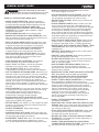 3
3
-
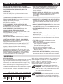 4
4
-
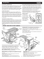 5
5
-
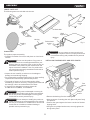 6
6
-
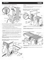 7
7
-
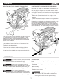 8
8
-
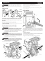 9
9
-
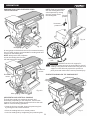 10
10
-
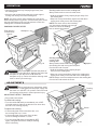 11
11
-
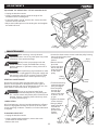 12
12
-
 13
13
-
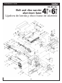 14
14
-
 15
15
-
 16
16
-
 17
17
-
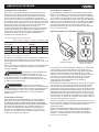 18
18
-
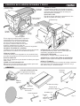 19
19
-
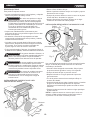 20
20
-
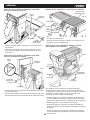 21
21
-
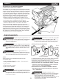 22
22
-
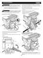 23
23
-
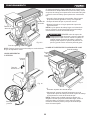 24
24
-
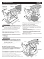 25
25
-
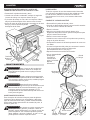 26
26
-
 27
27
-
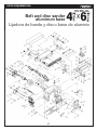 28
28
-
 29
29


KNOVA KN BD-46L El manual del propietario
- Categoría
- Herramientas eléctricas
- Tipo
- El manual del propietario
en otros idiomas
- English: KNOVA KN BD-46L Owner's manual
Artículos relacionados
Otros documentos
-
Ryobi BD4601G El manual del propietario
-
-
-
Skil 3376-01 El manual del propietario
-
-
Craftsman 351215140 El manual del propietario
-
-
-
-
Surtek LB521B El manual del propietario