Home2O H11L-421-MB Guía de instalación
- Categoría
- Artículos sanitarios
- Tipo
- Guía de instalación

04-13-2018
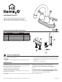
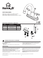
BATHROOM FAUCET
H02L-421-CH – Polished chrome nish with pop-up
H02L-421-BN – Brushed nickel nish with pop-up
H02L-421-ORB – Oil rubbed bronze nish with pop-up
PACKAGE AND HARDWARE CONTENTS
ADA
NSF 61
PART DESCRIPTION
QUANTITY
C
B
A
D
A Faucet assembly 1
B Lift rod and knob assembly 1
C Pop-up assembly 1
D Mounting nut 2
SAFETY INFORMATION
Please read and understand this entire manual before attempting to
assemble, operate or install the product.
WARNING
• Protect your eyes with safety glasses when cutting or soldering water supply
lines.
CAUTION
• If you solder the joints during installation, the seats, cartridges, and washers
must be removed before using a ame or the warranty will be voided on
these parts.
• Cover the drain to avoid losing parts.
PREPARATION
Before beginning assembly of product, make sure all parts are present. Compare
parts with package contents list and hardware contents. If any part is missing or
damaged, do not attempt to assemble the product.
Contact customer service for replacement parts.
Estimated Assembly Time: 30 minutes
Tools Required for Assembly (not included): Adjustable Wrench, thread sealant
tape, Silicone, Groove Joint Pliers
Installations may vary depending on how the previous faucet was
installed. Supplies necessary for the installation of the faucet are not
all included; however, they are available wherever plumbing supplies
are sold.
Prior to beginning installation, turn off the hot and cold water lines, then turn
on the old faucet to release built-up pressure. When installing the new faucet,
hand tighten the connector nuts. DO NOT OVERTIGHTEN. Connections
that are too tight will reduce the integrity of the system.
Need Help? Please call our toll-free line at (877) 319-3757 (8 am to 5 pm CST) for additional assistance or service.
Homewerks Worldwide, LLC • Lake Bluff, IL 60044 • www.homewerksww.com

2
www.homewerksww.com
PRODUCT SPECIFICATIONS
SPECIFICATIONS SPECIFICATIONS
Max. Flow Rate: 1.2 GPM (4.54 LPM) at 60 PSI Washerless cartridges
ASME A112.18.1/CSA B125
Manufactured to include no more than 0.25% weighted average lead content
on wetted surfaces
NSF 61-9
Polished chrome, brushed nickel or oil rubbed bronze nish
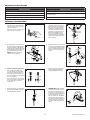
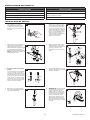
ASSEMBLY INSTRUCTIONS
1. Turn off water at the supply valve
under the sink or at the main water
supply, disconnect the supply line,
and remove old faucet.
Clean and dry surface area where
new faucet will be mounted.
1
5. Apply silicone to the underside of
the ange (1). Insert the pop-up
body (2) into the sink. Screw the
ange (1) onto the pop-up body
(2). The pivot hole (3) must face
the back or the sink. Use groove
joint pliers to tighten the nut (4)
But do not overtighten. Do not
turn the pop-up body (2) while
tightening the nut (4) or the sealant
may not seal properly. Clean away
any excess putty.
1
2
3
4
5
2. Place the gasket (1) onto the bottom
of the new faucet assembly (2). Place
the faucet assembly (2) through the
mounting holes in the sink. Secure the
faucet assembly (2) to the sink using
the mounting nuts (3) provided.
NOTE: If the sink is uneven, use
silicone under the gasket (1).
2
1
3
2
6. Remove the pivot nut (1). Install the
horizontal rod (2) and the stopper
(3), as shown (4). Hand tighten the
pivot nut (1). Attach the horizontal
rod (2) to the strap (5) using the
clip (6).
2
1
3
4
5
6
6
3.
Connect water supply lines.
Use 1/2" IPS faucet supply lines
(1) (not included) or use coupling
nuts (2) (not supplied) with ball-
nose risers (3) (not included). Use
wrenches to tighten the connections.
Do not overtighten.
Turn water supply or shut-off valve
back on and check for leaks. If leaks
occur, gently tighten the faucet
connections.
3
1
2
3
7. Insert the lift rod (1) through the
faucet assembly (2) and into the
strap (3). Tighten the screw (4).
2
1
4
3
7
4. Remove the stopper (1) and ange (2).
Screw the nut (3) all the way down,
and push the gasket (4) down.
1
2
4
3
4
8. IMPORTANT: After installation
is complete, remove the aerator to
ush the water lines. Do not lose
the gasket (1) in the aerator. Turn
on the water supply and allow both
hot and cold water to run for at
least one minute each. This ushes
away any debris that could cause
damage to internal parts. While the
water is running, check for leaks.
Turn off the water and replace the
aerator.
1
8

3
www.homewerksww.com
TROUBLESHOOTING
PROBLEM POSSIBLE CAUSE CORRECTIVE ACTION
Leaks underneath handle. Bonnet has come loose or O-ring on cartridge
is dirty or twisted.
1. Move the handle to the OFF position. Unscrew the handle screw and remove
the handle.
2. Tighten the bonnet by turning it clockwise. Move the cartridge stem to the on
position. The leak should stop draining out from around the cartridge stem.
3. Shut off the water supply. Remove the bonnet by turning it counterclockwise.
Lift out the cartridge valve. Inspect the larger O-ring on the cartridge bonnet
and the smaller O-ring on the cartridge stem. Remove any debris from the
O-rings. If either O-ring is twisted, straighten it out. If either O-ring is damaged,
replace the cartridge by calling customer service.
4. Position the cartridge back into the faucet body. Make sure the ridges on the
two sides of the cartridge bonnet t into the grooves on the two sides of the
faucet body. Tightly screw the bonnet onto the faucet body.
5. Re-install the handle.
Water does not completely
shut off.
Rubber valve seat is dirty, stuck, or broken. 1. Shut off the water supply to the faucet that leaks.
2. Remove the handle on the problem side. Loosen the bonnet by turning it
counterclockwise. Lift out the cartridge assembly.
3. Inspect the rubber valve seat in the faucet body. If there is debris or brass
scrap on the surface of the seat, remove it. If the rubber seat is stuck tightly in
the water inlet hole, push it gently with a ngertip so that it moves up and
down smoothly. The spring (smaller end up) must be replaced underneath
the valve seat. If the rubber valve seat is worn out or broken, replace the
cartridge by calling customer service.
4. Replace the cartridge in the faucet body. Make sure that the ridges on the
two sides of the cartridge bonnet t into the grooves on the two sides of
the faucet body. Tightly screw the bonnet onto the faucet body.
5. Re-install the handle.
Faucet leaks around aerator. Aerator incorrectly tted. 1. Unscrew the aerator by turning it clockwise. Inspect the black rubber packing
inside the aerator. The rubber packing should be at.
2. Screw the aerator onto the spout end and tighten.
Improper water pattern. Aerator dirty or small parts inside aerator
improperly installed.
1. Remove the aerator from the spout end by turning it clockwise.
2. Gently ush the small parts inside the aerator to clear away any debris.
3. Re-install the small parts as shown in the exploded diagram. Metal screens
must be at and plastic supporter must be straight.
4. Screw the aerator onto the spout end and tighten.
CARE AND MAINTENANCE
Clean periodically with a soft cloth. Avoid abrasive cleaners, steel wool, and harsh chemicals as these will dull the nish and void your warranty.
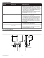
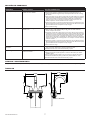
ROUGH-IN
4"
1-1/8"
7-1/8"
8-5/8"
4"
5"
6-7/8"
1/2"-14NPSM-2A
2-1/2"

4
www.homewerksww.com
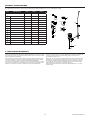
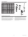
PRODUCT SPECIFICATIONS
For replacement parts, call our customer service department at (877) 319-3757, 8 a.m. - 5 p.m., CST, Monday - Friday.
PART DESCRIPTION PART # PART # PART #
8
2
13
14
9
11
12
10
7
6
5
3
1
4
H02L-421-CH
H02L-421-BN H02L-421-ORB
1
Hot handle RP13635CH RP13635BN RP13635ORB
2
Cold handle RP13636CH RP13636BN RP13636ORB
3
Screw RP50214 RP50214 RP50214
4
Bonnet RP70435 RP70435 RP70435
5
Washer RP64123 RP64123 RP64123
6
Cartridge assembly RP50168 RP50168 RP50168
7
Washer and spring RP22008 RP22008 RP22008
8
Mounting nut RP56001 RP56001 RP56001
9
Aerator assembly RP30275CH RP30275BN RP30275ORB
10
Wearable ring RP70077 RP70077 RP70077
11
Clip RP70106 RP70106 RP70106
12
O-ring RP60008 RP60008 RP60008
13
Lift rod and knob RP40293CH RP40293BN RP40293ORB
14
Pop-up assembly RP40027CH RP40027BN RP40027ORB
5-YEAR LIMITED WARRANTY
The distributor warrants to the original consumer purchaser this product to be free from defects in
material and workmanship under normal use in residential applications. At its option, the Company
will provide repair parts or replace defective product when the product is used in accordance
with the manufacturer’s specications.
Use of mild abrasive, abrasive or chemical cleaners may damage the nish of the faucet. We
recommend cleaning your faucet with a soft cloth, moistened with water. Damage resulting
from the use of abrasive or chemical cleaners SHALL VOID THIS WARRANTY.
This warranty is not applicable to any products or parts of products where damage is caused
by use of non-genuine parts; is due to installation error, product misuse, negligence or faulty
maintenance; or where the product is not installed according to local building codes.
sreplacement, and any indirect, incidental or consequential damages, losses, injury or costs
of any nature. This warranty is in lieu of and excludes all other warranties, conditions and
guarantees, whether expressed or implied, including without restriction those of
merchantability or tness of use.
Liability under this warranty will not exceed the purchase price for the product claimed to
be defective by the original consumer purchaser. Some states or provinces do not allow
the exclusion or limitation of consequential damages so the above limitations or exclusions
may not apply. This warranty gives you specic legal rights and you may also have other
rights which vary from state to state, or province to province.
Inquiries regarding warranty claims can be directed to (877) 319-3757, 8 a.m. - 5 p.m., CST,
Monday - Friday.

5
GRIFO PARA BAÑO
H02L-421-CH – Acabado de cromo pulido con pop-up
H02L-421-BN – Acabado niquel pulido con pop-up
H02L-421-ORB – Acabado bronce frotado con aceite con pop-up
PAQUETE DE HARDWARE Y CONTENIDO
ADA
NSF 61
PARTE DESCRIPCIÓN
CANTIDAD
C
B
A
D
A Montaje de grifería 1
B
Montaje de la varilla de
elevación y perilla
1
C Ensamblaje emergente 1
D Tuerca de montaje 2
INFORMACIÓN SOBRE LA SEGURIDAD
Por favor, lea y comprenda la totalidad de este manual antes de intentar armado,
manejo o instalación del producto.
ADVERTENCIA
• Proteja sus ojos con gafas de seguridad al cortar o suministro de agua de
soldadura líneas.
PRECAUCIÓN
• Si soldar las articulaciones durante la instalación de la grifería, los asientos,
cartuchos y arandelas deben ser removidos antes de utilizar una llama o la
garantía será anulada en estas partes.
• Cubra el desagüe del fregadero para evitar perder partes.
PREPARACIÓN
Antes de empezar el montaje del producto, asegúrese de tener todas las piezas.
Compare las piezas con la lista del contenido del paquete y el contenido de
hardware. Si alguna parte falta o está dañada, no intente ensamblar el producto.
Póngase en contacto con el servicio al cliente para las piezas de repuesto.
Tiempo estimado de ensamblaje: 30 minutos
Herramientas necesarias para el ensamblaje (no incluidas): Llave mecánica, Groove
Alicates de junta, llave de tubo, destornillador Phillips, y las tuberías de suministro,
Silicona, Alicates para juntas Groove
Instalaciones pueden variar en función de cómo se instaló la bañera previa y grifo
de la ducha. Suministros necesarios para la instalación de la llave de agua no están
incluidos; Sin embargo, están disponibles siempre que sea de fontanería suministros
se venden.
Antes de comenzar la instalación, desactive las líneas de agua caliente y fría,
a continuación, encender la vieja bañera y ducha grifo para liberar la presión
acumulada. Al instalar el nuevo grifo, apriete a mano las tuercas de conexión.
NO APRIETE. Las conexiones que son demasiado apretados reducirán la
integridad del sistema.
¿Necesitas Ayuda? Llame a nuestra línea gratuita al (877) 319-3757 (8 am a 5 pm CST) para obtener asistencia o servicio adicional.
www.homewerksww.com

6
www.homewerksww.com
ESPECIFICACIONES DEL PRODUCTO
ESPECIFICACIONES ESPECIFICACIONES
Caudal de ujo máximo: 4,54 LPM (1,2 GPM) a 60 PSI Cartuchos sin arandelas
ASME A112.18.1/CSA B125
Fabricado a incluir no más de 0,25% de contenido de plomo promedio pon-
derado en supercies mojadas
NSF 61-9
Cromo pulido, níquel cepillado y acabado en bronce aceitado
INSTRUCCIONES DE MONTAJE
1.
Cierre el agua en la válvula de suministro
bajo el fregadero o en el principal
suministro de agua,desconecte la línea
de alimentación y retire la llave vieja.
Supercie limpia y seca donde se montará
nuevo grifo.
1
5.
Aplique silicona a la parte inferior de la
brida (1). Inserte el cuerpo emergente
(2) en el fregadero. Atornille la brida (1)
en el cuerpo emergente (2). El oricio
de pivote (3) debe quedar hacia la parte
posterior o el fregadero. Use alicates de
unión de ranura para apretar la tuerca
(4) pero no apriete demasiado. No gire
el cuerpo emergente (2) mientras
aprieta la tuerca (4) o el sellador puede
no sellar correctamente. Limpie
cualquier exceso de masilla.
1
2
3
4
5
2.
Coloque la junta (1) en la parte inferior del
conjunto del nuevo grifo (2). Coloque el
conjunto del grifo (2) a través de los
oricios de montaje en el fregadero. Asegure
el conjunto de la llave (2) al fregadero
usando las tuercas de montaje (3) provistas.
NOTA: Si el fregadero no es uniforme, use
silicona debajo de la junta (1).
2
1
3
2
6.
Retire la tuerca de pivote (1). Instale la
varilla horizontal (2) y el tope (3), como
se muestra (4). Apriete a mano la tuerca
de pivote (1). Conecte la varilla
horizontal (2) a la correa (5) usando el
clip (6).
2
1
3
4
5
6
6
3.
Conecte las líneas de suministro
de agua:
Use líneas de suministro de grifos IPS de
1/2 "(1) (no incluidas) o use tuercas de
acoplamiento (2) (no incluidas) con eleva-
dores de punta esférica (3) (no incluidos).
Utilice llaves para apretar las conexiones.
Vuelva a conectar el suministro de agua
o la válvula de cierre y compruebe si hay
fugas. Si se producen fugas, apriete suave-
mente las conexiones de la llave.
3
1
2
3
7.
Inserte la varilla de elevación (1) a través
del conjunto de grifería (2) y en la correa
(3). Apretar el tornillo (4).
2
1
4
3
7
4.
Retire el tope (1) y la brida (2). Atornille
la tuerca (3) completamente hacia abajo, y
empuje la junta (4) hacia abajo.
1
2
4
3
4
8.
IMPORTANTE: Una vez completada
la instalación, retire el aireador para
enjuagar las tuberías de agua. No
pierda la junta (1) en el aireador. Abra
el suministro de agua y permita que el
agua fría y caliente funcionen durante
al menos un minuto cada vez. Esto
elimina cualquier residuo que pueda
dañar las partes internas. Mientras el
agua está en funcionamiento, verique
si hay fugas. Apague el agua y reemplace
el aireador.
1
8

7
www.homewerksww.com
SOLUCIÓN DE PROBLEMAS
PROBLEMA POSIBLE CAUSA ACCIÓN CORRECTIVA
Fugas debajo de manejar. El capuchón se aojó o la junta tórica en el
cartucho está sucia o doblada.
1. Mover la palanca a la posición OFF. Aoje el tornillo de la manija y retire la manija.
2. Apriete el capó girando en sentido horario. Mueva el vástago del cartucho a la
posición de encendido. La fuga debe dejar de escape hacia afuera de todo el vástago
del cartucho.
3. Cierre el suministro de agua. Quite el capó girando en sentido antihorario. Levante la
válvula del cartucho. Inspeccione la junta tórica más grande en el capó del cartucho y
la junta tórica pequeña en el vástago del cartucho. Quite toda la suciedad de las
juntas tóricas. Si se tuerce o bien O-ring, enderezarlo. Si bien la junta tórica está
dañada, reemplace el cartucho llamando al servicio al cliente.
4. Coloque el cartucho en el cuerpo del grifo. Asegúrese de que los salientes de los dos
lados del capuchón del cartucho encajen en las ranuras de los dos lados del cuerpo del
grifo. Atornille rmemente el capuchón al cuerpo del grifo.
5. Vuelva a instalar el mango.
El agua no se cierra por completo. Asiento de la válvula de goma está sucio,
atascado o roto.
1. Cierre el suministro de agua para el grifo que gotea.
2. Quite la manija en el lado problema. Aoje el capó girando en sentido antihorario.
Levante el conjunto de cartucho.
3. Inspeccione el asiento de la válvula de goma en el cuerpo del grifo. Si hay escombros
o desechos de cobre en la supercie del asiento, retírelo. Si el asiento de goma se pega
rmemente en el oricio de entrada de agua, empuje suavemente con la yema del dedo
para que se mueva hacia arriba y hacia abajo suavemente. El resorte (más pequeño
extremo hacia arriba) debe ser reemplazado por debajo del asiento de la válvula. Si el
asiento de la válvula de goma está desgastado o roto, reemplace el cartucho llamando
al servicio al cliente.
4. Sustituya el cartucho en el cuerpo del grifo. Asegúrese de que los salientes de los dos
lados del capuchón del cartucho encajen en las ranuras de los dos lados del cuerpo del
grifo. Atornille rmemente el capuchón al cuerpo del grifo.
5. Vuelva a colocar el mango.
La llave tiene ltración alrededor
del aireador.
Aireador incorrectamente instalado. 1. Destornille el aireador girándolo hacia la derecha. Inspeccione el empaque de caucho
negro en el interior del aireador. La junta de goma debe ser plana.
2. Atornille el aireador sobre el extremo del surtidor y apriete.
Modelo del agua inadecuada. Aireador partes sucias o pequeñas dentro
aireador mal instalados.
1. Quite el aireador del extremo del pico girando en sentido horario.
2. Enjuague suavemente las piezas pequeñas en el interior del aireador para eliminar
cualquier residuo.
3. Vuelva a instalar las piezas pequeñas, como se muestra en el diagrama de despiece.
Pantallas de metal deben ser planas y partidario de plástico deben vser rectas.
4. Atornille el aireador sobre el extremo del surtidor y apriete.
CUIDADO Y MANTENIMIENTO
Limpie periódicamente con un paño suave. Evite limpiadores abrasivos, estropajo de acero y químicos cáusticos porque podrían dañar el terminado y anular la garantía.
ÁSPERA EN
4"
1-1/8"
7-1/8"
8-5/8"
4"
5"
6-7/8"
1/2"-14NPSM-2A
2-1/2"

8
www.homewerksww.com
LISTA DE REPUESTOS
Para piezas de repuesto, llame a nuestro departamento de servicio al cliente al (877) 319-3757, 8 a.m.-5 p.m. CST, Lunes - Viernes.
PARTE DESCRIPCIÓN PARTE# PARTE# PARTE#
8
2
13
14
9
11
12
10
7
6
5
3
1
4
H02L-421-CH
H02L-421-BN H02L-421-ORB
1
Manija caliente RP13635CH RP13635BN RP13635ORB
2
Manija frío RP13636CH RP13636BN RP13636ORB
3
Tornillo RP50214 RP50214 RP50214
4
Capó RP70435 RP70435 RP70435
5
Lavadora RP64123 RP64123 RP64123
6
Conjunto de cartucho RP50168 RP50168 RP50168
7
Lavadora y primavera RP22008 RP22008 RP22008
8
Tuerca de montaje RP56001 RP56001 RP56001
9
Ensamblaje del aireador RP30275CH RP30275BN RP30275ORB
10
Anillo usable RP70077 RP70077 RP70077
11
Acortar RP70106 RP70106 RP70106
12
Junta tórica RP60008 RP60008 RP60008
13
Levante la varilla y la perilla RP40293CH RP40293BN RP40293ORB
14
Ensamblaje emergente RP40027CH RP40027BN RP40027ORB
GARANTÍA LIMITADA DE 5 AÑOS
El distribuidor garantiza al comprador original que este producto está libre de defectos en
materiales y mano de obra bajo condiciones normales de uso en aplicaciones residenciales.
A su propia discreción, la Compañía proporcionará las piezas de reparación o sustituir el
producto defectuoso cuando el producto se utiliza de acuerdo con las especicaciones del
fabricante.
El uso de productos de limpieza abrasivos, abrasivos o químicos leves puede dañar el acabado de
la grifería. Se recomienda limpiar el grifo con un paño suave, humedecido con agua.
El daño resultante por el uso de limpiadores abrasivos o químicos anulará esta garantía.
Esta garantía no es aplicable a cualquiera de los productos o partes de productos casos
de daños causados por el uso de piezas que no sean originales; se debe a un error de
instalación, mal uso del producto, negligencia o mantenimiento inadecuado; o cuando el
producto no se instala de acuerdo con los códigos de construcción locales.
Esta garantía excluye los cargos de mano de obra o daños incurridos durante la instalación,
reparación o sustitución, y cualquier daño indirecto, incidental o consecuente, pérdidas,
heridas o costos de cualquier naturaleza. Esta garantía reemplaza y excluye todas las otras
garantías, condiciones y garantías, ya sean expresas o implícitas, incluyendo, sin restricción
alguna aquellas de comercialización o aptitud de uso.
La responsabilidad bajo esta garantía no excederá el precio de compra del producto
supuestamente defectuoso por el comprador original. Algunos estados o provincias no
permiten la exclusión o limitación de daños consecuentes, por lo que no pueden aplicarse las
limitaciones anteriores. Esta garantía le otorga derechos legales especícos y usted también
puede tener otros derechos que varían de estado a estado o de provincia a provincia.
Las preguntas sobre las reclamaciones de garantía se pueden dirigir al (877) 319-3757,
8 a.m.-5 p.m. CST, Lunes - Viernes.
-
 1
1
-
 2
2
-
 3
3
-
 4
4
-
 5
5
-
 6
6
-
 7
7
-
 8
8


Home2O H11L-421-MB Guía de instalación
- Categoría
- Artículos sanitarios
- Tipo
- Guía de instalación
en otros idiomas
Artículos relacionados


Otros documentos
-
DANCO 10524 Guía de instalación
-
HOMEWERKS 3310-250-RB-B Guía de instalación
-
Homewerks Worldwide 21-B42WYHW-Z Guía de instalación
-
-
-
-
-
 Tosca 255-K820-T Manual de usuario
-
 Tosca 255-K820-SS-T Guía de instalación
-

