Hunter Fan 99770 El manual del propietario
- Tipo
- El manual del propietario

M3873 • 01/21/21 • © 2021 Hunter Fan Company
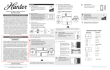
Remote Control of Fan is Erratic
• Make sure the battery is installed correctly.
• Install a fresh battery.
Multiple Remote Issues
• If you have multiple remotes or multiple remote-controlled fans installed on the same circuit breaker and you
are experiencing interference or faulty operation of your remote controls, please go to
www.HunterFan.com/FAQs and click “How do I properly install multiple remote-controlled fans?” for
information on how to correct this issue.
CEILING FAN REMOTE
CONTROL
Model 99770
7
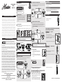
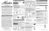
Installing the battery
Installation
Wiring
Trouble Shooting
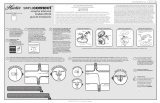
Cradle Installation
Before installation, use the pull chains to set the fan speed to HIGH
and the light to ON. Ensure the power is OFF at the outlet box and wall
switch location before proceeding with installation.
Turn Power
OFF
OFF
2
3
1
Option 1
Option 2
4
5
Remove the canopy. If uncertain how to remove it, reference the
fan’s owner’s manual. With wiring exposed, it may be helpful
to note existing wire connections or take a digital photo for
reference. Remove the wire connectors that connect the wires
from the outlet box to the fan, leaving the grounding wires
connected.
Turning off the power
Using screws
Using Adhesive Strip
Connecting the ground wires
Wiring the receiver to the fan (continued)
Installing the receiver
Removing the canopy
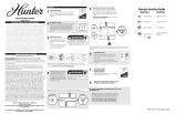
Choose the hanging system that most closely resembles the one used by your fan, and install
the receiver and wire as directed.
You may have installation issues if the fan is installed on an angled ceiling. For assistance, call
1-888-830-1326.
OR OR OR
Note: Some fans may have considerable excess lead wire. For easier canopy installation, cut the excess wire,
leaving a minimum of 8” remaining. Re-strip the fan lead wires 1/2”. Place remaining excess wire into the ceiling
electrical box. The bracket and fan must remain properly grounded.
Turn the splices upward and push them carefully back through the hanger bracket into the outlet box.
Spread the wires apart, with the grounded wires on one side of the outlet box and the ungrounded
wires on the other side of the outlet box.
Note: If you are uncertain about wire colors or connections, please contact a qualied electrician.
Ceiling
Plate
Receive
r
Canopy
Receiver
Canopy
Receiver
Canopy
Ceiling
Bracket
A
Fan Body
Cable Tie
To access the battery compartment, remove the small
Phillips head screw that secures the battery door to the
remote control.
Replace the used battery with a CR2032 battery when
necessary. The battery should be installed with the positive
(+) side up.
Phillips
Head
Screw
Battery
Door
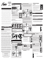
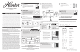
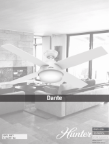
Using the orange wire connectors, connect the blue wire from the receiver to the blue wire
(or possibly black with white stripe wire) from the fan. Connect the yellow wire from the
receiver to the black wire from the fan.
Using an orange wire connector, connect the 3 grounding wires (green, green/yellow stripe, or
bare copper) coming from the ceiling, downrod, and hanging bracket.
6
Using the orange wire connectors, connect the black wire (ungrounded) from the
ceiling to the black wire from the receiver. Connect the white wire (grounded) from the
ceiling to both the white wire from the receiver and the white wire from the fan.
AFTER ALL WIRES ARE CONNECTED and secured with wire connectors, re-install the
canopy.
Wiring the receiver and fan to the ceiling
Turning on the power
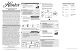
Reference the included remote function card for
information on how to use your control!
F
R
O
M
C
E
I
L
I
N
G
black
white white (grounded)
black (ungrounded)
F
R
O
M
R
E
C
E
I
V
E
R
F
R
O
M
F
A
N
white
ON
ON
Turn Power
IMPORTANT
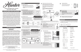
Install the cradle bracket to the wall with the included screws.
You have two options to install the included remote control cradle to the
wall. Choose which path works best for you.
Choose your cradle installation location.
If you are installing into drywall, drill two 9/64 width holes using
the cradle bracket as a guide. Gently hammer the included
drywall anchors into the pre-drilled holes.
Press the cradle bracket against the wall and hold rmly for 30
seconds.
Apply the adhesive sticker to the back of cradle bracket per the
instructions on the adhesive sticker.
Slide the cradle onto the mounted bracket.
Remove the cradle from the
cradle bracket.
8
9
Note: If your need to pair your remote, remove the battery door.
Cycle power to the fan by turning power off and back on at the
wall switch (or circuit breaker if necessary). Within three minutes,
press the pair button on the remote.
To prevent faulty operation, please disconnect power
from all other ceiling fans within range while pairing.
The remote transmitter is already paired to
the receiver and ready to use.
Examples of receiver connections
F
R
O
M
R
E
C
E
I
V
E
R
black
blue
yellow
blue
F
R
O
M
F
A
N
F
R
O
M
F
A
N
F
R
O
M
C
E
I
L
I
N
G
B
R
A
C
K
E
T
(Grounding)
Green/Yellow
Stripe
Green/Yellow
Stripe
F
R
O
M
C
E
I
L
I
N
G
WARNING
All wiring must be in accordance with national
and local electrical codes ANSI/NFPA 70. If you
are unfamiliar with wiring or in doubt, consult a
qualied electrician.
WARNING
To avoid possible electrical shock, before
installing your fan, disconnect the power by
turning off the circuit breakers to the outlet box
associated with the wall switch location.
If you are installing multiple remote-controlled fans
on the same circuit breaker,
you may need to perform a few extra steps to prevent interference or faulty operation of
your remote controls.
Go to www.HunterFan.com/FAQs and click “How do I properly install multiple remote-
controlled fans?” for more information.
This device complies with part 15 of the FCC Rules.
Operation is subject to the following two conditions: (1)
this device may not cause harmful interference, and (2) this
device must accept any interference received, including interference that may cause
undesired operation.
This device complies with RSS-210 of Industry Canada. Operation is subject to
the following two conditions: (1) this device may not cause interference, and (2)
this device must accept any interference, including interference that may cause
undesired operation of the device.
This equipment has been tested and found to comply with the limits for a Class
B digital device, pursuant to Part 15 of the FCC Rules. These limits are designed
to provide reasonable protection against harmful interference in a residential
installation. This equipment generates, uses and can radiate radio frequency
energy and, if not installed and used in accordance with the instructions, may cause
harmful interference to radio communications. However there is no guarantee that
interference will not occur in a particular installation. If this equipment does cause
harmful interference to radio or television reception, which can be determined
by turning the equipment off and on, the user is encouraged to try to correct the
interference by one or more of the following measures: Reorient or relocate the
receiving antenna, Increase the separation between the equipment and receiver,
Connect the equipment into an outlet on a circuit different from that to which the
receiver is connected. Consult the dealer or an experienced radio/TV technician
for help. Note: Any changes or modifications to the transmitter or receiver not
expressly approved by Hunter Fan Company may void one’s authority to operate
this remote control. Chemical burn hazard. Keep batteries away from children.
This remote contains a lithium button cell battery. If a new or used lithium button/
coin cell battery is swallowed or enters the body, it can cause severe internal burns
and can lead to death in as little as 2 hours. Always completely secure the battery
compartment. If the battery compartment does not close securely, stop using the
product, remove the batteries, and keep it away from children. If you think batteries
might have been swallowed or placed inside any part of the body, seek immediate
medical attention. Dispose of cells properly and keep away from children. Even
used cells may cause injury.
This product conforms to UL Standard 1917.
WARNINGS
HUNTER FAN COMPANY CONTROL LIMITED WARRANTY
The Hunter Fan Company makes the following limited warranty to the original purchaser
of the Control (“Control”): Your Control is warranted to be free from defects in material and
workmanship for a period of one year from the date of sale. If the Control malfunctions or fails
within the warranty period due to a defect in material or workmanship we will replace it free
of charge. IF THE ORIGINAL PURCHASER CEASES TO OWN THE CONTROL, THIS WARRANTY
AND ANY IMPLIED WARRANTY, INCLUDING BUT NOT LIMITED TO ANY IMPLIED WARRANTY OF
MERCHANTABILITY OR FITNESS FOR A PARTICULAR PURPOSE, ARE VOIDED. THIS WARRANTY
IS IN LIEU OF ALL OTHER EXPRESS WARRANTIES. THE DURATION OF ANY IMPLIED WARRANTY,
INCLUDING, BUT NOT LIMITED TO, ANY IMPLIED WARRANTY OF MERCHANTABILITY OR FITNESS
FOR A PARTICULAR PURPOSE, IN RESPECT TO ANY CONTROL, IS EXPRESSLY LIMITED TO THE
PERIOD OF THE EXPRESS WARRANTY SET FORTH ABOVE FOR SUCH CONTROL. This warranty
excludes malfunctions or failures which were caused by repairs by persons not authorized by
us, mishandling, improper installation, modications, or damage to the Control while in your
possession, or unreasonable use. This warranty does not apply to batteries or to deterioration
or damage to the product caused by the use of faulty batteries. To obtain a replacement, return
your Control postage prepaid along with proof of purchase to Hunter Fan Company Service
Department at 7130 Goodlett Farms Pkwy., Memphis, TN 38016. IN NO EVENT SHALL HUNTER
FAN COMPANY BE LIABLE FOR CONSEQUENTIAL OR INCIDENTAL DAMAGES. SOME STATES DO
NOT ALLOW LIMITATIONS ON HOW LONG AN IMPLIED WARRANTY LASTS OR THE EXCLUSION
OR LIMITATIONS OF INCIDENTAL OR CONSEQUENTIAL DAMAGES SO THE ABOVE LIMITATIONS
OR EXCLUSIONS MAY NOT APPLY TO YOU. THIS WARRANTY GIVES YOU SPECIFIC LEGAL RIGHTS
AND YOU MAY ALSO HAVE OTHER RIGHTS WHICH VARY FROM STATE TO STATE.
Read and Save These Instructions

M3873 • 01/21/21 • © 2021 Hunter Fan Company
CONTROL REMOTO
PARA VENTILADOR DE
TECHO
Modelo 99770
7
Instalación o cambio de la batería
Instalación
Antes de instalar, use las cadenas para que la velocidad del ventilador
quede en la posición
ALTA y la luz en
ENCENDIDA.
Asegúrese de que
la alimentación esté
DESCONECTADA antes
de continuar con la
instalación.
2
3
1
5
4
Quite la campana para las instrucciónes de ensamble.
Quite los conectores que conectan los cables de la caja de salida
al ventilador, pero deje conectados los cables de puesta a tierra.
Desconecte la energía
Conecte los cables del receptor al ventilador
Conecte los cables del receptor al ventilador
Instalación del receptor
Quite la campana
Elija el sistema de suspensión que más se parezca al que utiliza su ventilador y monte el
receptor y conecte los cables según se indica.
Puede que tenga inconvenientes de instalación si el ventilador se monta en un techo
inclinado. Para asistencia, llame al 1-888-830-1326.
OR OR OR
Nota: Algunos ventiladores pueden tener un exceso considerable de cable conductor. Para una instalación más
fácil de la campana, recorte el cable y deje un mínimo de 8” (20 cm.) Pele 1/2” (1 cm) de los cables conductores
del ventilador. Coloque el resto del cable sobrante en la caja eléctrica de techo. El soporte y el ventilador
deben conservar una puesta a tierra adecuada.
Gire los empalmes hacia arriba y presiónelos cuidadosamente hacia atrás a través del
soporte de suspensión dentro de la caja de salida. Separe los alambres, con los alambres
puestos a tierra a un lado de la caja de salida y los alambres no puestos a tierra al otro lado
de la caja de salida.
Note: If you are uncertain about wire colors or connections, please contact a qualied electrician.
Para acceder al compartimiento de la batería quite el
pequeño tornillo estrella (Phillips) que ja la tapa del
compartimiento al conjunto del transmisor.
Reemplace la batería CR2032 según sea necesario. La
batería debe instalarse con el lado positivo (+) hacia arriba.
Tapa de la
batería
Tornillo
de la
batería
Usando los conectores de cable anaranjado, conecte el cable amarillo desde el receptor
hacia el cable negro proveniente del ventilador. Conecte el cable azul del receptor al
cable azul (o posiblemente negro con tira blanca) proveniente del ventilador.
Usando un conector de
alambre anaranjado de
la bolsa de materiales ,
conecte los 3 alambres
de puesta a tierra (verde,
verde con banda amarilla,
y cobre desnudo) del
ventilador, la varilla y el
soporte de suspensión.
6
8
Usando los conectores de cable anaranjados, conecte el cable negro (no aterrizado)
desde el techo hacia el cable negro del receptor. Conecte el alambre blanco
(aterrizado) desde el techo al cable blanco del receptor y al cable blanco del
ventilador.
Una vez que todos los cables estén conectados y sujetos con conectores de
cables, vuelva a colocar la campana.
Use el interruptor tirador de cadena
para establecer la velocidad del
ventilador a la posición ALTA antes
de la operación.
Conectando cables del receptor y del ventilador al techo
Conecte la energía
DESCONECTE
DESCONECTE
La energía
Placa
de techo
Recepto
r
Campana
Receptor
Campana
Soporte
de techo
Receptor
Cuerpo del
ventilador
Sujetacables
Receptor
Campana
D
E
S
D
E
E
L
R
E
C
E
P
T
O
R
negro
azul
amarillo
azul
D
E
S
D
E
E
L
V
E
N
T
I
L
A
D
O
R
D
E
S
D
E
E
L
T
E
C
H
O
negro
blanco
blanco
(con puesta
a tierra)
negro
(sin puesta a tierra)
D
E
S
D
E
E
L
R
E
C
E
P
T
O
R
D
E
S
D
E
E
L
V
E
N
T
I
L
A
D
O
R
blanco
¡IMPORTANTE!
CONECTE
CONECTE
La energía
9
Hacer referencia a la tarjeta de la función de control
remoto incluido para obtener información sobre
cómo utilizar el control!
Soporte de control remoto
Localización de fallas
Cableado
Opción 1
Opción 2
Utilizando tornillos
Utilizando una tira adhesiva
Instale el soporte de la base a la pared con los tornillos
incluidos.
Escoja la ubicación de instalación de la base.
Si está instalando sobre un panel de yeso, perfore dos oricios
de 9/64” de ancho usando el soporte de la base como una guía.
Martille con cuidado las anclas para panel de yeso incluidas en
los oricios previamente perforados.
Presione el soporte de la base contra la pared y sosténgalo
rmemente por 30 segundos.
Aplique la etiqueta adhesiva a la parte trasera del soporte de la
base según las instrucciones mostradas en la etiqueta adhesiva.
Deslice la base sobre el soporte ya montado.
Retire la base de su soporte.
Note: Si necesita sincronizar su control remoto, retire la compuerta
de las baterías. Alterne la alimentación al ventilador, apagándolo y
luego encendiéndolo de nuevo desde la pared (o en el interruptor
termomagnético si es necesario). Dentro de los siguientes tres
minutos, presione el botón sincronizar en el control remoto. Si la
sincronización fue exitosa, sonará un solo bip.
Para evitar una falla en la operación, desconecte la alimentación de todos los
otros ventilador de techo dentro del rango mientras realiza la sincronización.
El transmisor de control remoto ya debe
estar sincronizado con el receptor y estar
listo para usarse.
Examples of receiver connections
D
E
S
D
E
E
L
V
E
N
T
I
L
A
D
O
R
D
E
S
D
E
E
L
S
O
P
O
R
T
E
D
E
T
E
C
H
O
(Puesta a tierra)
Verde con banda
amarilla
Verde con banda
amarilla
D
E
S
D
E
E
L
T
E
C
H
O
El control remoto del ventilador funciona de modo errático
• Asegúrese de que la batería esté colocada correctamente.
• Instale una batería nueva.
Problemas de varios controles remoto
• Si usted tiene varios controles remoto o varios ventiladores controlados remotamente alimentados por
el mismo interruptor termomagnético y está experimentando interferencia u operación deciente de
sus controles remoto, por favor visite www.HunterFan.com/FAQs y haga clic en “How do I properly install
multiple remote-controlled fans?” para mayor información sobre cómo corregir este problema.
Para evitar posibles choques eléctricos,
antes de instalar su ventilador, desconecte
la alimentación apagando los interruptores
automáticos que alimentan a la caja de salida
asociados con el interruptor de pared.
ADVERTENCIA
Todo el cableado debe realizarse de acuerdo
con los códigos eléctricos locales y nacionales
ANSI/NFPA 70. Si no está familiarizado con
el cableado, o si tiene duda, consulte a un
electricista calicado.
ADVERTENCIA
Este dispositivo cumple con la parte 15 de las reglas FCC.
La operación está sujeta a las dos siguientes condiciones:
(1) este dispositivo no puede causar una interferencia perjudicial, y (2) este
dispositivo debe tolerar cualquier interferencia recibida, incluyendo interferencias
que puedan causar una operación no deseada.
Este dispositivo cumple con la norma RSS-210 de Industry Canada. La operación
está sujeta a las dos siguientes condiciones: (1) este dispositivo no puede causar
interferencia, y (2) este dispositivo debe tolerar cualquier interferencia, incluyendo
interferencias que puedan causar la operación no deseada del mismo.
Este equipo se ha probado y cumple con los límites para un dispositivo digital
clase B, de acuerdo con la Parte 15 de las reglas FCC. Estos límites están diseñados
para proporcionar una protección razonable contra la interferencia perjudicial en
una instalación residencial. Este equipo genera, usa y puede radiar energía de
radio frecuencia, y si no se instala y usa de acuerdo con las instrucciones, puede
causar interferencia perjudicial a la comunicación por radio. Sin embargo, no hay
garantía de que no pueda producirse interferencia en una instalación en particular.
Si este equipo causa alguna interferencia perjudicial a la recepción de radio o
televisión, lo que puede determinarse apagando y encendiendo el equipo; el
usuario debe tratar de corregir la interferencia aplicando una o más de las medidas
siguientes: Reoriente o reubique la antena receptora, aumente la separación entre
el equipo y el receptor, conecte el equipo a una salida de un circuito diferente
al circuito en que está conectado el receptor. Consulte con su representante de
ventas o con un técnico experimentado de radio/TV. Nota: Cualquier cambio o
modificación al transmisor o al receptor no aprobados expresamente por Hunter
Fan Company puede anular la autorización para operar este control remoto. Peligro
de quemadura química. Mantenga las baterías fuera del alcance de los niños. Este
control remoto posee baterías tipo botón de litio. Si una batería tipo botón de
litio, nueva o usada, es ingerida o ingresa al cuerpo, puede provocar quemaduras
internas graves y puede provocar la muerte en apenas 2 horas. Siempre cierre por
completo el compartimiento de las baterías. Si el compartimiento de las baterías
no está bien cerrado, deje de usar el producto, extraiga las baterías y manténgalas
fuera del alcance de los niños. Si cree que las baterías pueden haber sido ingeridas
o haber ingresado a cualquier parte del cuerpo, busque atención médica de
inmediato. Deseche las baterías de manera adecuada y manténgalas fuera del
alcance de los niños. Incluso las baterías usadas pueden provocar lesiones.
Este producto se ajusta al Estándar 1917 UL.
GARANTÍA LIMITADA DEL CONTROL REMOTO DE LA HUNTER FAN COMPANY
Hunter Fan Company establece la siguiente garantía limitada al comprador original del
control remoto (“Control”): garantizamos durante un año a partir de la fecha de compra
que su Control no tendrá defectos en materiales ni mano de obra. Si el Control presenta un
funcionamiento defectuoso o una avería dentro del período de garantía debido a un defecto
en el material o la mano de obra, lo reemplazaremos en forma gratuita. SI EL COMPRADOR
ORIGINAL DEJA DE POSEER EL CONTROL, ESTA GARANTÍA Y CUALQUIER GARANTÍA IMPLÍCITA,
INCLUYENDO, PERO SIN LIMITARSE A TODA GARANTÍA IMPLÍCITA DE COMERCIABILIDAD O
IDONEIDAD PARA UN PROPÓSITO PARTICULAR, QUEDA ANULADA. ESTA GARANTÍA SUSTITUYE
A TODAS LAS OTRAS GARANTÍAS EXPRESAS. LA DURACIÓN DE TODA GARANTÍA IMPLÍCITA,
INCLUYENDO PERO SIN LIMITARSE A CUALQUIER GARANTÍA IMPLÍCITA DE COMERCIABILIDAD
O IDONEIDAD PARA UN PROPÓSITO PARTICULAR, RELACIONADA CON CUALQUIER CONTROL,
ESTÁ EXPRESAMENTE LIMITADA AL PERÍODO DE LA GARANTÍA EXPRESA ESTABLECIDA
ANTERIORMENTE PARA DICHO CONTROL. Esta garantía excluye funcionamientos defectuosos
o fallas causados por reparaciones realizadas por personas no autorizadas por nosotros, mal
uso, instalación incorrecta, modicaciones, o daños al Control mientras esté en su posesión,
o por un empleo no razonable. Esta garantía no se aplica a las baterías ni al deterioro o daño
al producto causado por el uso de baterías defectuosas. Para obtener un reemplazo, devuelva
su Control con el franqueo prepago junto con una prueba de su compra al Departamento de
servicio de Hunter Fan Company, 7130 Goodlett Farms Pkwy., Memphis, TN 38016. HUNTER
FAN COMPANY NO SERÁ RESPONSABLE EN NINGÚN CASO DE DAÑOS RESULTANTES O
INCIDENTALES. ALGUNOS ESTADOS NO PERMITEN LIMITACIONES SOBRE LA DURACIÓN
DE UNA GARANTÍA IMPLÍCITA O LA EXCLUSIÓN O LIMITACIÓN DE DAÑOS ACCESORIOS O
PERJUDICIALES, ASÍ QUE LA LIMITACIONES O EXCLUSIONES ANTES MENCIONADAS PUEDEN
NO APLICARSE A USTED. ESTA GARANTÍA LE DA DERECHOS LEGALES ESPECÍFICOS,PERO
USTED TAMBIÉN PUEDE TENER OTROS DERECHOS QUE VARÍAN DE ESTADO A ESTADO.
LEA Y GUARDE ESTAS INSTRUCCIO
ADVERTENCIAS
ADVERTENCIAS
Si usted está instalando varios ventiladores controlados remotamente en
el mismo interruptor automático,
usted podría necesitar realizar algunos pasos adicionales para prevenir interferencia u
operación deciente de sus controles remoto.
Visite www.HunterFan.com/FAQs y haga clic en “Cómo instalar apropiadamente
múltiples ventiladores controlados remotamente” (How do I properly install multiple
remote-controlled fans?) para obtener información adicional.
-
 1
1
-
 2
2


Hunter Fan 99770 El manual del propietario
- Tipo
- El manual del propietario
en otros idiomas
- English: Hunter Fan 99770 Owner's manual
Artículos relacionados
-
 Hunter Fan 99106 El manual del propietario
-
 Hunter Fan 99394 El manual del propietario
-
Hunter Fan 99814 El manual del propietario
-
 Hunter Fan 99372 El manual del propietario
-
 Hunter Fan 99772 El manual del propietario
-
 Hunter Fan 99771 El manual del propietario
-
 Hunter Fan 99375 El manual del propietario
-
 Hunter Fan 99373 Ceiling Fan Remote Wall Control Manual de usuario
-
 Hunter Fan 59654 El manual del propietario
-
 Hunter Fan 27206 El manual del propietario


