
website: http://wwwAgeservice.com
e-maiL:http://www.lgeservice.condtechsup.htm!
E
AiR
'S
O0
DiTi
UAL
Sease read t_e ope 8ting it]sifter ors and safely pa"ec8,_,t o_"_s
carefL Iy a"_d tho_o, 9h y befo'e nstai rg _sd openat r f!! you
_(}os 8i colditioe_
,bEL3°UT,L.ISATI
eLI T U E
Veu ez ie et er_ ete_ ce guide dL ifSal:Or'_
,e ,_SL_ _, de oecu_ _e (:i.h-i_c/uses 878nt d proc:>_de_a
isstaaton et au fo_iclios eient de yore
A
ET
ACOINDIC_DORDS_IR[DE
LET
PO" 8vor iea L;I_'_; _ (y'; _" de 18;;-, /'{,:<)Si£_iC)*v:?S
=n.,_tr,._...._or.s ope ac @" y ....
de i_eguridad c s dad, sa tol:al 7_er_tear_tes d_. ii"_stalar y
su acond c o salon de aire de venta_ a,
E
I0
MODELS, MODELES, MODELOS: R5050,,R5207

FOR YOUR RECORDS
Write down the model and serial numbers here:
Model #
You can find them on a Ilabelon the side of each unit.
_aler"s Name
Date Purchased
Staple your receipt here for proof of purchase.
READ THIS MANUAL
inside you will find many helpful hints on how to use and
maintain your air conditioner properly. Just a little preventive
care on your part can save you a great deal of time and
money over the life of your air conditioner.
You'll find many answers to common problems in the chart
of troubleshooting tips If you review our cha_ of
Troubleshooting Tips first, you may not need to cail for
service at a[k
, Contact an Authorized Service Center for repair or
maintenance of this unit. Call 1-800-243-0000 to
locate the nearest ASC.
• The air conditioner is not intended for use by young
children or invalids without supervision.
• Young children should be supervised to ensure that
they do not piny with the air conditioner.

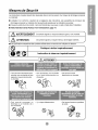
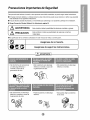
Safety Pre utions
To prevent injury to the user or other people and property damage, the following these instructions.
m In_rrect operation due to ignoring instructions will cause harm or damage. The seriousness is classified by
the following indications,
[] Because of the weight of the product, it is recommended that you have a helper to assist in the installation.
[] Use Cautiont Sharp Edges! See Warning, page 4.
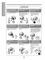
_Z_ WARNING This symbol indicates the possibility of death or serious injury. /
J
L_ CAUTION Thissymbolindicatesthepossibilityofinjuryordamageto
prope_ies only,
[] Meanings of symbols used in this manual are as shown below,
Be sure not to do this. "_
[ €__ Be sure to follow the instructions.
• Otherwise, it will cause electric
shock or fire due to heat
generation.
• It will cause electric shock or fire
due to heat generat:ion.
• it will cause electric shock or fire
due to heat generation.
• it wil_cause electric shock.
• it will _use electric shock or fire.
• I1:the power cord is damaged, it must
be replaced by the manulacturer or
its service agent or a similarly
qualified person in order to avoid a
hazard.
• This _uld _eadto health problems.
®

• They are sharp and may cause
an iniury.
!IAc ,o.l
• Water may enter the unit and
degrade the insulation _tmay
cause an e_ectdc shock,
• Since the fan rotates at high
sped during operation, it may
cause an iniury_
• Jtcould cause dust to
a_umulate on the heat
exchanger.
•This could injurethe _ts
or plants.
• _ not use this air conditioner to
preserve precision devices, food,
pets, plants, and art obiects
It may cause deterioration of
quality, etc
• Itmay cause a fire or • Use_ution when handlingthe
deformation of the cabinet, case.Grip it firmlyand do notaI_ow
ittoslip whileholding it.
• Useheavyglovestoh_die
Sharp
fne
!_ • DONOT
allowthe
casetosiide
_ .>..;': against
, it may cause an electric shock.

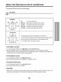
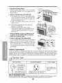
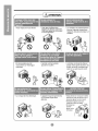
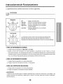
About the ntro, ls on the air conditioner
The controls will look like one of the following.
Off
' ,
_\\_ Low
'---. J,,)-°°°/
Off
High Fan
Low Fan
High Cool oCooling with high speed fan operation,
Low Cool - Cooling with bw speed fan operation,
oTurns air _nditioner off.
- High speed fan operation without cooling.
- Low speed fan operation without _ling.
This automatically controls the temperature of the indoor air.
Turn the knob so that arrow points to the larger marks for greater cooling,
Point the arrow to the smaller marks for more moderate cooling,
(i.e. the higher number, the greater cooling)
. FOR NORMAL COOLING
!. Turn the operation switch to the High Cool or the Low Cool setting.
2. Set the thermostat control to the desired temperature mark _ (the mid-point is a good
starting position), if the _oom temperature is not satisfactory a_er a reasonable time, adjust the
control to a cooler or warmer setting, as appropriate.
. FOR MAXIMUM COOLING
1. Turn the operation switch to the High Cool se_ing.
2. Set the thermostat control to the largest % temperature mark.
,. FOR QUIETER OPERATION
1. Turn the operation switch to the Low Cool setting.
2. Set the thermostat control as needed.
• CAUTION
When the air conditioner has been performed its cooling operation and is turned off or set to the
fan position, wait at least 3 minutes before resetting to the cooling operation again.

Additional controls and important information.
Air Direction
• ADJUSTING THE AIR DIRECTION USING THE HORIZONTAL AIR.DEFLECTOR CONTROL
Using the control tabs, the air flow can be directed
to the left, right, straight ahead, or any combination
of these directions.
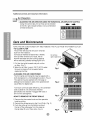
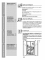
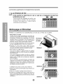
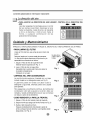
Care and Maintenance
TURN THE AIR CONDITIONER OFF AND REMOVE THE PLUG FROM THE POWER OUTLET.
• TO CLEAN FILTER
The air filter will become dirty as it removes
dust from the inside air.
It should be washed at least every 2 week& Donotforce
If the air filter remains full of dust, the air openoropentofar_
flow will decrease and the cooling capacity
will be reduced, possibly damaging the unit.
1. Pull the inlet grille forward and pull out the
air filter. (Fig. 1)
2. Wash the air filter in warm 104ff: (40_) water.
Be sure to shake off all the water before
replacing the filter.
• CLEANING THE AIR CONDITIONER
The front grille and Inlet grille may be wiped with a
cloth dampened in a mild detergent solution. (Fig. 2)
The cabinet may be washed with mild soap or
detergent and lukewarm water then polished with
Liquid Wax for Appliances.
Fig, 1
Fig, 2
To ensure continued peak efficiency, the condenser
coils (outside of uniO should be checked
periodically and cleaned if clogged with soot or
dirt from the atmosphere.
,, HOW TO REMOVE THE FRONT GRILLE
1. Remove the thermostat knob and the operation
knob by pulling
2. Remove the screw securing the Front: Grille, (Fig. 3)
3. Push the grille up from the bottom and pull
the top of the grille away from the case as
the top tabs lift out of their slots. (Fig. 4)
Fig, 3
Fig. 4

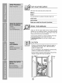
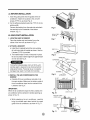
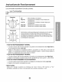
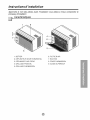
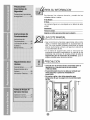
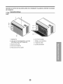
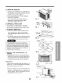
Features and Installation
Learning parts name prior to installation will help you understand the installation procedure.
1 9
8
1. CABINET
2. HORIZONTAL AIR DEFLECTOR
3. COOL AIR DISCHARGE
4. FRONT GRILLE
5. 1NLET GRILLE
6. AIR FILTER
7 KNOBS
8. AIR INTAKE
9. UPPER GUIDE

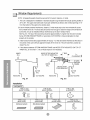
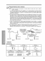
Window Requirements
NOTE: All supporting parts should be secured to firm wood, masonry, or metal.
1. This unit is designed for installation in standard double hung windows with actual opening widths of
22" to 36" The upper and lower sash must open sufficiently to allow a clear vertical opening of 13"
from the bottom of the sash to the window stool.
2.If storm window presents interference, fasten a 2" wide woed strip to the inner window sill across
the fulllwidth of the sill. The wood strip should be thick enough to raise the height of the window sill
that the,unit can be installed without interference by the storm win_w frame.
See Fig. 5-2. The top of the wood strip should be approximately si4"higher than the storm window
frame (STORM WINDOW FRAME) or wood strip (OUTDOORS) to help condensation to drain
properly to the outside.
3. Install a second wood strip (approximately 6" long by 11/_z,,wide and same thickness as first strip) in
the center of the outer sill flush against the bah off the inner sill. This will raise the L bracket as
shown Fig. 5-2
4. if the distance beh,¢eenSTORM WINDOW FRAME and WOOD STRIP MOUNTED ON TOP OF
INNER SILL is more than 1'*,two of wood strips are not necessa@.
iNNER WOOD STRIP MOUNTED 1" MAX,
Fig. _1 Fig. _2
HARDWARE ]
TYPEA: 1lEA TYPE B:5EA TYPE C:3EA
..... (SHORTSCREW) (WOODSCREW) ...... (L BRACKET)
TYPED: lEA
(SEALSTRIP)
(Adhesive backed)
TYPE E:lEA
(SASHSEAL)
(Notadhesivebacked)
E
E
TYPE F: 2EA
(GUIDE PANEL)
TYPE G: 1EA
(SUPPORT BRACKET)

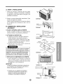
A. BEFORE INSTALLATION
1. Insert the guide panels into the guides of the,air
conditioner. Fasten the curtains to the unit with
screws (TYPE A), as shown Fig. 6.
2. Cut the adhesive-backed seal strip (TYPE D) to the
window width.
Remove the backing from the seal strip and attach
the seal strip to the underside of the bottom
window (Fig, 7)
B. NOW START INSTALLATION
1, LOCAT/NG UNIT IN WINDOW
Open the win_3w and mark center line on the
_nter of the inner sill, as shown in Fig. 8.
2. ATTACH L BRACKET
a. Install the L brackets behind the inner window
sill, with short side of bracket as show& Use the
2 screws (TYPE A) provided.
b The bracket helps to hold unit securely in place.
Be sure to place bracket ewe flush against back
of inner sill. See Fig, 9.
During the foHowing step, hold unit firmly until
window sash is lowered to top channel behind
side panel frames. Personal injury or property
damage may result if unit falls from window.
& INSTALL THE AIR CO IN THE
WINDOW
& Carefully lift the air _nditioner and slide it into
the open window. Make sure the bottom guide of
the air conditioner drops into the notches of the
L bracket. See Fig. 9.
IMPORTANT:
When the air conditioner drops into the L bracket, the
air _nditioner will be centered in window opening as
shown in Fig. 10.
b. While steadying the air conditioner, carefully
bring the window sash down behind the upper
guide of the air conditioner, as shown in Fig. 11.
TYPE A
Fig. 6
Fig. 8
iNNERSILL
OUTER S_LL
OUTSIDE
Fig. 9
Fig. 10
UPPER GUIDE
_TTOM --
GUIDE
TYPE A
L BRACKET
TYPE A
INSIDE
_ENTER LINE
\
CENTER LINE
ADOUT1/4°
Fig. 11 L BRACKET

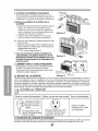
4. SECURE THE GUIDE PANELS
Extend the guide panels (TYPE F) to fill the window
opening using 4 _rews (TYPE B) to secure them, as
shown in Fig. 12,
5, INSTALL THE SASH SEAL AND SASH LOCK
& Cut the sash seal (TYPE E) to the window width
Stuff the sash seal between the glass and the
window to prevent air and insects from getting into
the room, as shown in Fig. 12.
b. Fasten the L bracket using a screw (TYPE A), as
shown in Fig. 12o
Remove the screws that secure the cabinet and
base pan in the right side.
Fasten the supo_t bracket (TYPE G) using a
removed screw. Attach the suport bracket (TYPE G)
in the inner window sill with a screw (TYPE B), as
shown Fig. 13.
7. Window installation of room air conditioner is now
completed. See ELECTRICAL DATA for attaching
power cord to electrical' outlet.
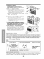
C. HOW TO THE DRAIN PIPE
In humid weather, excess water may cause the BASE
PAN to overflow. To drain the water, remove the
DRAIN CAP and secure the, DRAIN PIPE to the rear
hole of the BASE PAN. (Fig. 14) Press the drain pipe
into the hole by pushing down and away from the fins
to avoid injury.
REMOVAL FROM WINDOW
L BRACKET
TYPE
TYPE B
SASH SEAL
(TYPE E}
Fig. 13
Support Bracket (TYPE G)
u
('_) Push _
,p
DRAINPIPE_,f_ DRAIN CAP
Fig, 14
Turn the air conditioner off, disconnect the _wer cord, remove the L bracket, the screws and Suppo_ Bracket
installed through the top and bottom of the guide panels, and save for reinstaliation later. Close the guide panels.
Kee#ng a firm grip on the air conditioner, raise the sash, and carefully tilt the air conditioner backward, draining
any condensate. Lift the air conditioner from the window and remove the sash seal from _tween the windows.
Electrical Data
Line Cord Plug Use Wall Receptacle Power Supply
oo, oodorooy
um_aoces cut
emove the
" grounding prong
from the plug, _,
Power supply cord with
3-prong grounding plug
Standard 125V, 3-wire grounding
receptacle rated 15A, 125V AC
Use, 15 AMP, time
delay fuse or circuit
breaker.
USE OF ON CORDS
Because of potential safety hazards, we strongly discourage the use of an extension cord_However, if you wish to
use an extension cord, use a CSA certified!UL-listed 3-wire (grounding) extension cord, rated 15A, 125V.

fore you for
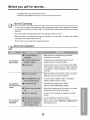
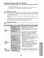
Troubleshooting Tips save time and money!
Review the chart below first and you may not n_d to call for service.
Normal Operating
' You may hear a pinging noise caused by water being picked up and thrown against the condenser
on rainy days or when the humidity is high. This design feature heJps remove moisture and improve
efficiency.
• You may hear the thermostat click when the compressor cycles on and off.
• Water will collect in the base pan during high humidity or on rainy days. The water may overflow
and drip from the outdoor side of the unit.
• The fan may run even when the compressor does not.
Abnormal Operation
Air conditioner
does not start
Air conditioner
does not cool as it
should
Air conditioner
Make sure the air conditioner plug is pushed
completely into the outJet.
Check the house fuse!circuit breaker _x and
replace the fuse or reset the breaker.
If power failure occurs, turn the mode control to Off.
When power is.restored, wait 3 minutes to restart the
air conditioner to prevent tripping of the _mpressor
overload.
Make sure there are no curtains, blinds, or furniture
blocking the front of the air @nditioner.
Turn the knob to a higher number. The highest
setting provides maximum cooling.
Clean the filter at least every 2 weeks.
See the care and Maintenance section.
When the air conditioner is first turned on, you ne_
to allow time for the room to cool down,
Check for open furnace floor registers and cold air
returns.
• See Air Conditioner Freezing Up below.
, Set the mode control at High Fan or High _ol with
thermostat at I or 2.

Reportezicilesnumeros,de modeleetdeserierespectifs
desunitesinterieureetextedeure:
Unit_ int_ieure
N° de serie
Ces numeros sont inscrits sur i'etiquette apposee sur le
flanc de chaque unite.
Raison sociale du vendeur
Date d'achat
Agrafez vorte requ ici pour la preuve d'achat.
LISEZ CE MANUEL
• Le present manuel communique de nombreuses et
precieuses informations quanta I'utilisation eta la
maintenance de ce climatiseur. Un entretien preventif
simple se traduit par une Iongevite accrue du climatiseur,
d'oQ une importante economie de temps et d'argent.
Les conseils de d6pannage permettent de r6soudre les
roblemes les plus courants. La _nsultation pr6alable des
onseils de depannage peut eviter le recours a un
technicien de reparation,
Toute intervention (r_paration ou maintenance)de cet
appareil do,it _tre confiee a un technicien agree.
Ce climatiseur n'est pas destine a _tre utilise sans
surveillance par de jeunes enfants ou des personnes
Veiller _ ne pas laisser de jeunes enfants joiuer avec le
climatiseur.

Mesums de curite
Les instructions cFapres doivent 6tre observ6es dans ie but de pr6venir tout risque de dommages corporels
ou mat6riels.
i L'utilisation non conforme, resultant de la negligence des instructions, est su_eptible de provoquer des
dommages _rporeis ou mat6riels dont la gravit6 est signal6e par les indi_tions suivantes
II A cause du poids Iourd du produit, il est recommand6 que vous ayez un aide a l'aide dans I'installation.
i Faites Attention! Bords Pointus! Voir Avertis_ment, page 14,
'_ AVERTISSEMENT cesymbolesignale un risque de blessure grave, voire moselle /
|
Z_ ATTENTION ce symbole signale un risque limit6 aux dommages materiels. J
II Les significations respectives des symboles utilises duns ce manuel sont indiquees ci-dessou&
(" Pratique, a eviter imperativement
instruction a observer imperativement _
r _ AVE_I_sEME_)
L
• Tout mauvais branchement peut
entrainer une surchauffe de votre
appareil et causer electrocution
ou incendie.
+Ceci pourrait provoquer un
• Ceci provoquera une surchauffe
et un risque d'electrocution ou
d'incendie.
. Ceci pourra_ causer
electrocution ou incendie.
eiectrique ou un incendie, dQ &
une surchauffe.
, IIy a risque d'61ectrocu_on,
®
• _ci _urrait mener au probleme
de sant&

•VousrisquezdevousHesser. • L.'eau_ut s'infiltrer dans
Iappareil et affecter Iisolement
Cela peut 6gaiement provoquer
un ch_ 61e_rique.
• Le ventilateur de refroidissement
toumant &grande vite_e dans
Fappareil,cela peut provoquer un
accident,
• De Eapoussiere pourrait
s'accumuler sur I'_hangeur
thermique.
• IIy arisque de choc 6lec_rique.
• L'animal comme la #ante
peuvent en _uffrir,
. Lec_imatiseurnedoltpas6treutilisepour
prot6gercertainsap_reitsdeF6cision des
alimentsdesanimaux,desplantesetdes
objetsd'art Laqualiteri_ue d'en_u_ir,
•L'appareil risque deprendre feu
ou _e_ffret risque d'etre
_form&
•Faitesatten_onenmanipuiantleboitier
Saisissezle bo_tierrefinementetne[e
laissezpasglissertoutenletenant
•Employezlesgants!ourdspour
manipulerlebokieraubesoin
•Ne_aissezpas
le['Wtier

Instructions de Fon ionnement
Les commandes ressemblemn,t rune des suivantes.
Les Commandes
Off
i
_'_ LOW
/) Coo_
Off
High Fan
Low Fan
High Cool
Low Cool
-- Met le climatiesur hors tension.
-- Fait font[onner le ventilateur & haute vitesse sans
refroidissement.
-- Fait fonctionner le ventilateur a basse vitesse sans
refroidissement.
-- Reffoidit tout en ventilant & haute vitesse.
-- Refroidit tout en ventilant & basse vitesse.
Thermostat
4 5 6 Cette fonction contr61e automatiquement la temperature de fair ambiant
_"--,,_ Toumez le bouton en direction des chiffres les lus grands pour un
3 ,,_/ _f -"_"-..",, ..7 refroidissement plus pui_ant:. Faites-le pointer vers les peitits chiffes si
it [ ",__ vous desirez une ambian_ moins fra_'che.Plus le chiffre est e[eve, plus
.,_ _, ) i,,,, le refroidissement est puissant.
,,.:,,._..8
. POUR UN REFROIDiSSEMENT NORMAL
1. Tournez le bouton des fonctions operation & ]a position de reroidissement eleve High Coo,I ou
de refroidissement failble Low Cool.
2 Reglez le thermostat a la temperature desire _ (ia position du milieu est un bon point de
depart) Si la temperature ambiante n'est pas satifaisante apres un certain temps, ajustez la
position a un degre plus froid ou plus chaud, au besoin.
• POUR UN T MAXIMAL
1. Tournez le bouton des fonctions operation _ [a position de refrodissement e]eve High Cool.
2. Reglez le Themostat _ la position ]a plus froide, representee par le plus grand % des chiffres.
° POUR UN FONCl T PLUS SILENCIEUX
1. Toumez ]e pouton des fonctions operation au reglage de refroidissement faibie Low C_l.
2 Reglez le thermostat a la temperature voulue.
• MISE EN GARDE
Apres avoir change la position du climatiseur de "Cool" (froid) a "Off" (ferme) ou "Fan"
(ventilateur), attendez au moins 3 minutes avant de le reme_re _ la position "Coo]".

Commandes supplentaires et renseignemenits importants.
La Direction de I'air
, POUR AiJUSTER LA DIRECTION DE L'AIR A L'AIDE DE LA COMMANDE DE DIRECTION
HORJZONTALE DE L'AIR
Envous servant des languettes de contr61e, vous
pouvez didger la circulation d'air vers la gauche, __ _
ia droite, droit devant ou n'importe quelle
combinaison de ces directions.
Nettoyage et Entretien
FERMEZ LE CLIMATISEUR ET DEBRANCHEZ _ FICHE DE LA PRISE DE COURANT.
. NETTOYER LE FILTRE
Le fi]tre & air se salira inevitablement puisqu'ille les
particules de poussiere de I'air ambiant. Vous devriez
_e nettoyer a toutes les 2 semaines. Si le fi]tre
demeure sale, ]a circulation d'air diminuera et ia
capacite de refroidissement en sera s6rieusement
diminu6e, _uvant mCme endommager _'appare&
1.Tirez sur le gdHage d'admission vers vous en prenant
_esdeux languettes;retirez le filtre & air (Schema 1).
2.Nettoyez ]e fit]re dans I'eau tiede (environ
104°Fo40_). Assurez=vous de bien secouer ]e fi]tre et
de retirer toute l'eau avant de le remettre en place,
• NETTOYER LE CLIMAT]SEUR
Vous pouvez nettoyer [e grillage fronta_ et le grillage
d'admis.sion a I'aided'un chiffon humecte d'un detergent
doux (Schema 2),
Vous pouvez egalement nettoyer ie boitier en utiUisant
un savon ou detergent doux et de ]'eau tiede, puis
faites-ie briller & _'aide de cite _iquide pour appareils
electromenagers.
Afin de maintenir une performance constante de
_'appareih les bobines de condensateur (du c6te
exterieur) doivent etre veifiees refuH6rement;
nettoyezqes si elles sont b[oques par la suie ou par
_essaletes provenant du dehors.
Neforcez pas
pour ourvr[ret
ne I'ouvrez
pastroploin
Schema 1
Schema 2
• COMMENT ENLEVER LE GRILLAGE FRONTAL
1.Retirez _es boutons du thermostat et des fonctions en
tirant dessus.
2_Retirez la vis quifient ]e grillage frontal (Schema 3).
3. Poussez sur le gdHage vers le haul _ parflr du bas, et
tkez sur _edessus de fagon & ]'eloigner du boqfler; les
languettes superieures sortiront de leurs fentes
(Schema 4).
Schema 3
Schema 4

Instructio, ns d'in allation
Apprendre le nom des piec,es avant I'installation vous aidera a mieux comprendre le
processus d'installation
1 9
8
5
I. BO/TIER
2. DEFLECTEUR D'AIR HORIZONTAL
3, DECHARGE D'AIR FROID
4, GR4LLAGE FRONTAL
5. GRILLAGE D'ADMISSlON
6. FILTREA AIR
7. BOUTON
8. PRISE D'ADMISSlON
9. GUIDE SUPERIEUR

Dimensionsdela fen#tre
REMARQUE: Toutes les pieces de support doivent 6tre ancrees sol!dement dans du bois
franc, de la magonnerie ou du metal.
1. Cet appareil a ere congu pour 6tre installe darts des fenetres doubles & guiflotine dont la
largeur d'ouverture varie entre 22 pc et 36 pc. Le ch&ssis du haut et celui du bas doivent
s'ouvrir suffisamment pour permettre une ouverture verticale de 13 pc & pa_ir du bas du
ch&ssis jusqu'au rebord de la fenetre.
2. Si le cadre de la fenetre exterieure gene !'installation en n'offrant pas une pente de drainage
suffisante, fixez une cale de bois de 2 poi5Omm de large sur toute la largeur du rebord
interieur de la fenetre. La cale de bois doit 6tre assez epaisse pour remonter la hauteur du
rebord interieur de la fenetre, de maniere & ce que le climatiseur puisse 6tre installe sans
probleme. Voir le schema 5-2. Le dessus de la cale de bois doit depasser le cadre de la
fenetre d'environ 3/4pc afin de creer une pente qui facflitera le drainage de la condensation
vers I'exterieur.
3. Fixez une deuxieme cale de bois (de 6 po/150mm de long, 1 1/2 po/38 mm de large et de la
meme epaisseur que la premiere) au centre du rebord exterieur de la fenetre, en la coingant
contre I'arriere du rebord interieur. Vous souleverez: ainsi le support en L ou celui pour le
rebord de la f,enetre selon le cas, tel qu'illustre au schema 5_2.
4. Si la distance entre "CALE DE BDIS MONTEE SUR LE DESSUS DU REBORD INTERIEUR" et "CADRE
DE _ DOUBLE FENETRE" est plus de 1 pc, deux bandes en bois ne sont pas necessaires
RE_RD 1POMAX.
CALE DEBOIS MONTEE
_NTERIEUq
Schema 5-i Schema 5-2
MATERIEL REQUIS POUR L'INSTALLATiON I
TYPE A: @6:i I TYPE B: @6:5 TYPE C: Qte:3
..... (VisCoupe) (Vis& bo!s) ...... (L Crochet)
TYPE E: Qte:l
(Bande d'_tancb_ite)
(Sals endosadhesif)
TYPED: @e:l
(Banded'_tanch_it_)
(Endos adhesif)
E
TYPE F: Qte:2 TYPE G: Qte:l
(P_ne.aux couli_ts) (_utenir le crochet)

A. AVANT L"INSTALLATION
1. Inserez _espanneaux cou_issants dans _esguides
du ciimatiseur, Attechez les panneaux coulissants
& I'appareil en vous servant des vis de type A, tel
qu'illustre au Schema 6.
2. Coupez la bande d'e.tancheite autocoflante (Type
D) selon la largeur de la fenetre.
Reflrez rendos autocollant de _abande et coflez-la
sur le dessous de la fenetre du bas. (Voir le
Schema 7)
B. COMMENCEZ L'INSTALLATION
1.PLACEZ L 'APPAREIL DANS LA FENETRE
Ouverz la fen_tre et faites une marque ligne au
_ntre du interieur tel quTHustre au Schema &
2, ATTACHEZ LE SUPPORT EN L
a. _nstallez les consoles L derriere le seuil de la
fenetre interieure, avec le c6te court de la
console _mme montr& Utilisez les 2 vis (Type
A) foamis. Le support sert & maintenir I_appareil
en place de fagon p_ussecuritaire.
b. Assurez-vous de le fixer contre _'arri¢re du
rebord interieur Voir Schema 9,
Durant les etapes qui suivent, tenez le climatiseur
fermement jusqu'& ce que le cadre de la fenetre
soit descendu et fermement appuy6 sur la rainure
superieure, qui se trouve derriere les panneaux
lateraux La chute de I appareil pourrait causer
des blessures ou des dommages a la propriet&
3. INSTALLEZ LE CLIMATISEUR A LA FENF:TRE
a. Levez doucement le climatiseur et gHssezqe
darts la fenetre ouverte. Assurez-vous que le
guide sous le climatiseur tombe darts les coches
du support en L. Voir le Schema 9.
IMPORTANT :
Lorsque le cHmatiseur tombe dans le mensula en
Lle climatiseur sera maintenant centre dans _a
fen_tre, tel qu'iilustre au Schema 10.
b. Pendant que vous stabilisez _ecHmatiseur,
de_endez tranquitement la glissiere de la
fenetre en arriere du guide superieur du
climatiseur, te! qu'i!lustre au Schema ! 1,
TYPE A
Schema 6
TYPE A
REBORD
DE INTERIEU R
REBORD 17"RE A INTER_EUR
DE EXTERIEUR
UGNE CENTR_E
EXTERIEUR
Schema 9 LCROCHET
Schema 10
CADRE DELA
CADRE DE LA
BANDE
GUIDE DU --
DES_US
ABOUTV_°
Schema 11 LCROCNET

4, ATTACHEZ LES PANNEAUX COULISSANTS
¢:tirez les panneaux couHssants de fagon & ce qu'ils
occupent route I'ouverture de la fenetre et attachezqes
& l'aide des 4 vis (Type B),.tel qu'illustr6 au Schema 12.
5. INSTALLZ LA BANDE ET LE VERROU DE LA
a. Coupez la bande d'etancheite de la glissiere selon la
largeur de la fenetre. Bourrez I'espace entre la
fenetre et le verre avec la bande de la glissiere de
fagon a empecher _'airet Jesinsectes d'entrer dans
la pfuece, tel qu'iliustr6 au Schema 12,
b. Vissez le verrou de la glissiere en vous servant
d'une vis de type A tel qulilustre au Schema 12.
6, a. Enleverlesvisqui obtJennent_acasseroledeplacardetba_
dansle _n c6t&
b. A_.acherle crochetdesu_rt (TYPEG} I'utili_flon d'unevis
enlevee.Atiacherie crochetde suport(TYPEG) dansle sill
defenetreinterieuravecunevis
(_PE B)_commeindiquee_hema 13.
7, Vous avez maintenant complete rinstallation de
vorte ctimatiseur, Consultez la section sur ta LES
MESURES DE SECURITE ELECTRIQUES pour tous
les details du branchement du fil d'almentation a la
prise de courant.
C,COMMENTFIXERLE TUYAUD'EVACUATION
Entemphumide, I'eau_ut causerle debordementdu BAC
DEBASE.Pour6vacuer I'eau,enlevez le couvercie
d'evacuationet fixezle tuyau d'@¢acuation_ I'orificearriere
du BAC DE LA BASE (Schema !4)
LE RETRAIT DE LA FENETRE
VERROU DE
LA GLISSIERE
Type B
BANDE
OETANCt,,_EIT#.
DELAGL/SSIERE
Schema 12
Schema 13
Soulenir/e Creche1
-- (TYPEG)
)Pendre !
CAPUCHON
D_EVACUA'TI( TUYAU
_hema 14 D'EVACUATHON
Toumez le bouton des fonctions & la position "Off"' (hors tension), debranchez le fil d'alimentation et retirez le
verrou de _aglissiere et les vis instali6esau haut et au bas des panneaux couNssant& Conservez ces vis
pour route installation u_terieure. Refermez les panneaux coulissants. En tenant soli,dement le cHmatiseur,
soulevez la glissiere de la fenere a guHIotione et penchez lentement Yappareil par en arriere en prenant soin
de reciter I'eoedent d'eau qui pourrait cou_er. Glissez te climatiseur vers _adroite et sortez-ie de la fenetre;
retirez ensuite _abanded' etancheit6 de la glissiere qui se trouve entre les fenetres
Donn es sur !eletric te
Fiche du cordon d'alimentation Utilisez ce type de prise murale Source d'alimentation
"b
......... rNecoupeznin'enlevez-_
enaucun_ labroche
de mi_ &la massede
I Fil d"alimentation avec
fiche & 3 broches de _pe
raise & la masse
Receptacle standard de 125V
3 ills avec raise a la masse,
capacite de 15A,125V CA
Utilisez un fusible
retardement de 15 AMP'
ou un disjoncteur
L"UTILISATION DE CORDONS D'
A _use desdangerspotentielsnousvous d_n_[_lons fortementI'util[sationde_rdons d'extensionToutefois,sivow. tenez
&lesutiliser,_rvez-vous d'uncordond'extension_ 3filshomologu__r FACNOR,dontla capaciteeside 15A,125V.

Avant de pla r un appel de
Quetques co,nseilspour vous depunner:
Epargnez temps et argent! Revisez le tableau ci-dessous et vous eviterez
peut-#tre un appel de service co#teux.
Fonctionnementnormal
• IIse peut que vous entendiez un cliquettement cause par l'eau qui est soulevee et projetee contre
le condensateur Iors des jours de pluie ou Iorsque le taux d'humidite est eiev& Cette caractefistque
sert a reduire I'humidite et ameliorer I'efficacite de I'appareil.
• II se peut que vous entendiez le thermostat emettre des d_lics Iorsque le compresseur se met
en/hors fonction.
• Ueau s'accumulera dans le bac du fond lots des jours tres humides ou des jours de pluie, L'eau
peut deborder et s'egoutter a rextedeur de I'appareii,
• Le ventilateur peut fonct[onner m6me sile compresseur est inactifi
Fonctionnement anormal
Le cfimatiseur
Le climatiseur
ne refroidit pas
de mani_re
efficace.
Le climatiscur
• Assurezwous de bien enfoncer la fiche du cHmatiseur dans
la prise de _urant.
• Wfif[ez le fusible ou _edisjoncteur, remplacez le fusible ou
remettez le disjoncteur en fonction
•S'ily a eupan_ de oourant,toumez la commandedes
modesala positionhorscircuit Off. Apr_savoir ramene[e
courant,attendez3 minutesavant de reparflrle
c]imatiseur,cequi emp,_cherade d_c]encher]asurcharge
du compres_ur
•Assurez-vous d'61oigner tout ddeau, store ou meuble
•Toumez [e _uton de reglage&un numero pluselev& Le
chiffre le plus _leve procureun rdroidissement maximum.
•Nettoyez reguliCrement le filtre (au moins & toutes los
deux sem_nes). Consu]tezla section des instructionsde
fonctionnementa _ sujet,
•Lorsque vous mettez le c]imatiseur en marche pour la
premiere fois, vous devez lui laisser suff[samment de
tem_ pour retro[d[rla piece.
•V_rifiez si los registres du systeme de chauffage au
plancheret les retoursd'aJrfroidsont fermes.
•Consu_tezlanJbrique"Leclimatiseur est geW'ci-dessous.
• R_glez la _mmande des modes & I&_sition 6_evee du
venti_ateur High Fan ou de refroidissement _lev6 High
Cool en ajustant le thermostat & i ou 2,

PARA SU INFORMACION
Escdba aqui los nOmeros de serie y modelo de las
unidades exterior e interior:
N__ Modelo
N9_rie
Los n_meros figuran en una etiqueta en el lateral de cada
unidad.
Distribuidor
Fecha decompra
Adjunte_ reci_ aquipara proof que io adquirib.
LEA ESTE MANUAL
Aqui encontrara numerosas sugerencias sobre como
utilizar y mantener adecuadamente su acondicionador de
aire. Con unos cuantos cuidados preventivos se puede
ahorrar mucho tiempo y dinero a Io largo de la vida OtiFde
su acondicionador de aire.
En la tabla de sugerencias para la resoluci6n de
probiemas encontrara respuestas a la mayoria de los
problemas m_s comunes. Si _nsulta primero la tabla de
Sugerencias para la resoluoi6n de problemas, quiz_ ni
siquiera necesite avisar al servicio t6cni_.
Consulte _n el servicio t_nico autorizado sobre la
reparacion o el mantenimiento de esta unidad.
• Et acondicionador de aire no de_ ser utilizado pot
niSos pequeSos o personas inestables sin
sup.ervisibn.
, Es preciso vigilar a los niSos pequeSos para
a_gurarse de que no juegart con el acondicionador
de aire.

Precauciones Importantes de Seguridad
Para prevenirtanto lesions al usuadou otras personascomo _5os materiales,es precisoseguirestas instrucciones.
II El man,ejoin_rrec_o debidoa la inobservanciade est_s instruccionespu_e _usar lesions o daSoscuya gravedad
esta dasificada en las siguientes indicacion.es.
II A _use del peso pesado del producto, _ r_omienda que usted tenga a un ayudante a partid_a en la in_alaci6n.
II Tenga P_cauci6n! Bordes Afilados! Vet Advertencia, p_ina 24,
_ ADVERTENCIA Este simbolo indi_ la posibilidad de lesiones mortales o graves. /
_J
Z_ PRECAUCION Est:e simbolo indica la posibilidad de lesiones o da_os
materiales.
i El significado de losslm_los utiliza_s en este manual se indica a continuaci6n,
Asegi3rese de no hacerlo.
J
__ Asegurese de seguir Ilas instrucciones.
f [ _ADVERTENCIA ]
• De otra forma, eHo_asionaria
una descarga electrica o
incendio a causa de la
generaci6n de calor.
• Ello ocasionarla una descarga
• EIIo ocasionaria una descarga
electrica o incendioa causa
la generaci6n de calor.
•EHoocasionaria una descarga
electrica o incendio.
ele,ctricao incendioa causa de
la generaci6n _ calor.
.Puede ocasionar una descarga
electrica.
®
• Esto _dria dirigir al #°oblema
de la salud.

PRECAuclON1
• Esto 3odria causar heridas.
• El agua podria entrar en ia
unidad y degradar el aislamiento.
Tambi_n podria causar una
sacudida electrica.
• Puesto que el ventilador gira a
alta ve_oddad durante la
operaci6n, podria ocasionar
heridas°
• Podria causar acumulamiento de
polvo en e_intercambiador de
calor.
• Esto podria causar una sacudida
el_ctdca.
• Esto _dda da_ar aJanimal o a
la plant&
• Esto podria causar un incendio o
deformar _acaja.
.No utilice este acondicionador de
aire para conservar disposiflvos de
precisi6n, alimentos y obietos de
arte; _ _nga tampoco _imales y
plantas cerca de 61.Esto _drla
deteriorar ia calidad, etc.
,Tengaprecauci6nalma_enarla
carcasa.Agarrebfirmementeyno
peL_itaquesedeslicemientraslo
mantiene
•Utiliceguantesgruesasparamaneiarla
carcasas_Qnla Bo_des
necesidad, afilados
quela
carcasase
deslice
contrasu
pie_!

In ruccionnes de Funcionamiento
La apariencia de lOScontroles sera como uno de,los siguientes.
Off
' ,
_\\_ Low
'---. J,,')-°°°/
Off ............Apaga el acondicionador,
High Fan -- Permite la vebcidad r_pida del ventilador.
Low Fan -- Permite la vebcidad lenta dei ventilador.
High Cool ............Permite el enfriamiento con el ventitador
en alta velooidad,
Low Cool -- Permite el enfdamiento con el ventiiador
en baja velocidad.
La temperatura del aire interno sera controlada automa.ticamente.
Mientras mas aita sea la marca mas frio estara el aire internio, La
temperatura se selecciona posicionando el control en la marca desead&
• PARA UN IAMIENTO NORMAL
1, Ponga el bot6n de operation en High Co,ol o Low Cool
2. Ajuste el control del Termostat en la marca deseada _ (usualmente el punto medio es un buen
punto para comenzar). Si la temperatura det cuarto no es satifactoria despues de un periodo de tiempo
razonable, ajuste el _ntrol de temperatura a una marca m_s grande (para una temperatura intema m,%
fria) o a una marca m_s peque_la (para que la temperatura interna sea menos fria).
. PARA UN ENFRIAMiENTO MAXIMO
1, Ponga el bot6n de operation en la marca mas grande_
2. Ponga el control del Termostat en la marca % ms.sgrande,
. PARA UNA OPERACi_N SILENCIOSA
1. Ponga el bot6n de operation en la marca m_s pequer_a.
2. Ponga el termostat en la temperatura interior desead&
• ADVERTENCIA
Cuando el aire acondicionado ha estado oiperando bajo la fase de enfriamiento y se apaga o se
ajusta ia posicion de ventilacion, espere por Io menos 3 minutos, antes de reiniciar ia operaci6n
de enfriamiento.

i
Controles adicionales e infon_acion importante.
La direction del aire
• PARA AJUSTAR LA DIRECCiON DEL AIRE USANDO CONTROL DE LA DIRECCION DEL
AIRE
Las dos leng0etas hodzontales para el control
de las rejillas le permiten descargar el aire __ _
hacia la izquierda, o algo de aire a la izquierda
y otro a la derecha, o todo el aire hacia el
frente, o cualquier combinaci6n de las
posiciones mencionadas.
Cuidado y Mantenimiento
APAGUE EL NRE ACONDICIONADO Y SAQUE EL ENCHUFE DEL TOMA CORRENTE DE LA PARED.
• PARA LIMPIAR EL FILTRO
Limpie el Filtro del Aire, que extrae el polvo interior del
cuarto.
Debe set lavado pot Io menos cada dos sernanas.
Un filtro de Aire sucio disminuye el flujo de aire y la
capacidad de enfriamiento se reduce.
1..Saque el Filtro de Aire de la parrilla frontal
halando hacia la izquierda (vet Fig, 1),
2. Lave el Filtro de Aire con agua tibia..
SacOadaio bien cuando este limpio para sacar la
humedad completamente.
Col6quelo en su lugar,
• L DEL AIRE A DO
No debe forzar
a abdr o abrir a
Io lejos,
Fig. 1
La parrilla frontal puede set limpiada con un trapo
htJm_o mojado en un detergente suave (vet Fig. 2). Fig, 2
El gabinete puede ser tavado con jab0n suave o
detergente y agua tibia, entonces pulido Cera Liquida
para aparatos.
Para asegurarse una eficiencia continua, las bobinas del
condensador (del lado expuesto al exterior) debe ser
revisado y lavado peri6dicamente sea pot que se tranque
con basura o polvo de la atmosferico.
Fig. 3
• COMO REMOVER LA PARILLA FRONTAL
1. Siaque el Filtro de Aire halando hacia la izquierda.
2. Saque el tornillo que asegura la Parrilla Frontal (ver Fig. 3)
3. Suelte el lado izquierdo primero.
Despues cuidadosamente hale desde la parte de
arriba y empuje hacia la derecha, Las teng0etas estan
aseguradas. (vet Fig. 4)
Fig. 4

Aprender el nombre de las partes antes de la instalacion le ayudara a entender el preceso
de instalacion.
1 9
8
1. GABINETE
2. DEFLECTOR HORIZONTAL DE AIRE
(VENTANILLAS VERTICAKLES)
3. SALiDA DE AIRE
4. REJiLLA FRONTAL
5. RECOLECTOR DE AIRE
6, FILTRO DE AIRE
7. PANEL DE CONTROL
8. TOMA DE AIRE
9, GUiA SUPERIOR

de la ventana
NOTA: Todas las partes que soportan la ventana deben de estar bien fijas a madera,
metal, o cemento.
1. La unidad estA diseSada para ser instalada en una ventana doble con anchos entre 22"
36".
y El borde superior e inferior deben de estar Io suficientemente abierto para permitir
un espacio vertical de por 1o menos 13" de la parte inferior de la ventana hasta la parte
superior de la ventana.
2. Si la sobre-ventana estorba col6quese una tira de madera de 2" pulg de ancho a Io largo
del descanso de la ventana pot la parte que de intemamente al cuarto, yen toda siu
extensi6n. La tira de madera debe ser Io suficientemente gruesa para eievar el des_nso
de ia ventana, de tal manera que Ia unidad de aire acondicionado pueda ser intalada sin
interferencia del marco de la sobre-ventana (storm window). Ver Fig, 5-2 La parte
superior de la tira de madera debe estar aproximadamente a 3/4_de pulg m_s aita que el
marco de la sobre ventana, (storm window) para ayudar a que el agua de condensaci6n
de la unidad fluya Ihacia afuera.
3. Instale una segunda tira de madera (aproximadamente 6" pulg. de largo, 1-Vz..pulg de
ancho y mismo espesor que la pnmeratira de madera) en el centro del descanso
exterior, pongaia contra ia parte posterior del descanso interior. Esto eievara, la mensuia
L como en la Fig. 5-2.
4. Si la distancia entre "FRANJA DE MADERA MONTADA SOBRE LA PARTE SUPERIOR
DEL DESCANSO INTERIOR" y "TtRA DE MADERA PARA LA MENSULA L Y
MENSULA DE ANTEPECHO" es masque 1% dos tiras de modetra no son necessarias,
ANTEPECHO 1"MAX.
FRANJADIEMADERA
Fig. 5-i Fig. 5-2
MATERIALES i
TIPO A: 11 T_PO B: 5 T_PQ C: 3
..... (TORNILLOCORTO) (TORNILLOMEDIANO) ..... (EL PARENTES.ISL)
1 E"
it,.. i r
TIPO D: 1 TIPO E: 1 TIPO F: 2 TIPO G: 1
(BANDA ADHES_VA) (BANDA DEL MARCO) (PANEL GUIA) (SOSTENGAPARENTES/Si
(Adhesivo posterior) (Noadhesivoposterior)
!

A. ANTES DE INSTALAR
1. Introduzca los paneies en los guias del aire
acondicionado. Las cortinas atornillelas _n los
tornillos (TI PO A), como en la Fig. 6.
2. Corte la banda adhesiva (TIPO D) y _lOquela
del ancho de la ventana,
Remueva el plastico de la banda adhesiva y
coloquela en la pa_e superior de el marco
inferior de la ventana. (Ver Fig. 7)
B; LA INSTLACION
1, COLOCA.NDO LA UNIDAD EN LA VENTANA
Abra la ventana y marque LINEA en el centro esta.
2, COLOQUE EL MENSULA EN L
a. _nsta_ebs soportes L detr_s de alf6izar intemo
de la ventana, con el _adocorto del soporte
oomo estA ilustrado, Ufllice 2 tornillos (TIPO A)
proveido&
b. La m6nsula ayuda a que la unidad se encuentre
firme, AsegQrese de porter la m6nsula en L
contra la parte posterior del descanso interior,
En las siguientes instrucciones, sostenga la
unidad firmemente hasta que la parte corrediza
de la ventana de,arise sobre la parte superior
del canal y por detr_s del marco de los paneles
corredizos. Puede haber lesiones o da_os si la
unidad se cae de la ventan&
3. INSTALE EL AIRE ACONDICiONADO A LA
VENTANA
a. Cuidadosamente levante el aire acondicionado y
col_uelo en el hoyo de la ventana. AsegQrese de
que la guia inferiordel aire acondicionado caiga
en lugar correcto del mensula en L Vet Fig. 9.
IMPORTANTE :
Cuando e! aire acondicionado sea fijado en el
support en L, el aire acondicionado ser& centrado
como pueden obsewar en la Fig. 10.
b.Mientras mantiene el aire aoondicionado en
posiciOn, cuidadosamente baje el borde de la
ventana superior hasta la guia superior del aire
acondicionado, como en la Fig.11.
T_POA
Fig. 6
Fig. 8
DESCANSO
ilNTER_OR
DESCANSO
TIPO A
EXTERIOR
EXTERIOR
Fig, 9 ELPAREP-_TE$1SL
Fig. 10 LINEA
BORDE DE LA VENTANA
SUPER_Of_
Fig. 11 ELPAR_NTESlSL
TIPO A
INTERIOR
LINEA DEL CENTRO

4. ASEGURE LOS PANELES
E_ienda los panties pararelLenarbs orificiosde la
ventana u_ndo los 4tornillos (TIPO B) como en ia Fig. 12.
5. INSTALE LA BANDA DEL MARCO
a. Corte la banda del marco del mismo ancho de la
ventana. Coloque la banda del marco entre el
vidrio y Uaventana para prevenir la penetraciOn al
cuarto de insectos y aire, como en ta Fig. 12.
b. AtomiJle la cerradura del marco usando un tornillo
TI PO A, como en la Fig. 12.
Quite los tornillos que aseguran el gabinete y
cacerola despreciable en eJlado corredo.
Abroche el parentesis de suport (TIPO G) usando
un torniHo quitado. Conecte ei parentesis de suport
(TIPO G) en el alfoizal interior de ventana con un
tomillo (TIPO B), cuando Fig 13.
7. La instalaci6n del aire acondicionado de ventana no
es_ra completa. Vea SEGUR/DAD ELECTR/CA pare
conectar /a extension e/ectrica a/ toma corriente.
C: COMO INSTALAR EL TUBO DE DESAGUE
En climas hQmedos, es posible que la BANDEJA
EVAPORADORA se _lenne de agua. Para quitar el
agua acumuiado, es preciso conectar el tubo de
desagQe, Quite _aTAPA DEL DESAGOE y conecte e_
TUBO a la BANDEJA EVAPORADORA. (Fig. 14)
C:ERRADURADELMARCO
TiPO A
T/PO B
Fig. 12 ..........
BANDADEL
MARCO
,T/PO B
TAPA DEL
REMOVERLO DE LA VENTANA Fig. 14
Apague el aire acond]cionado, desconecte el cordon ei@trico del toma cornente, remueva la cerradura del
marco y los tomillos instalados en la parte superior e inferior de los paneles, y guArdelos para reinstalaci6n.
Cierre ios paneles. Manteniendo el aire acondicionado fuertemente, levante el marco de la ventana, y
cuidadosamente, incline el aire acondicionado hacia atr_s, botando cualquier agua condensada. Deslice el aire
acondicionado 1"a la derecha, luego lev_tntelode la ventana y remu@ale la banda del marco de la ventana.
Informacion Electrica
CorcOn Electrico Utilice el enchufe de la pared Consume de Energia
fN 0 b cO,teba'O /'-I'_-'_-'="\.
o remuevalapunta
, l, .,,. J Utilice un fusible de
_._ kde]e_hu!e ,,,,,, \'-,.-g_._-J 15AMP o un
H Cord6n el@trico con Standard 125V, enchufe de 3 Interruptor
r,.n_puntaspara enchufar Lineas de i5A, 125V AC
USO DE CORDONES DE EXTENSION
Debido a] potencial de peligro a su seguridad bajo cJertas circunstancias recomendamos encaredidamente no
utiliar cordones de extension. Sin embargo, si usted decide usar un cordon de extension, es absolutamente
necesario que este sea un cordon listado bajo UL de tres espigas con conexiOn a tierra _lificado 15A, 125V.

Antes de avi r al rvicio Tecni
Tips para solucionar problemas
(Ahorre temopo y dnero) Cuando tenga algun problema primem consulte el cuadro que se
encuentra abajo y tat vez no necesite tlamar para solicitar servicb t6cnico.
OperaciSnnormal
• Durar te dias Iluviosos o cuando ]a humedad es alta usted puede escuchar un ruido met_ll_ causa
do pot agua recogida y arrojada contra el condensador. Esta caracter[stica ayuda a remover ]a
humedad y mejorar la eficiencia.
• Usted puede escuchar que e1termostato hace un click cuando se enciende o apaga el ciclo del
comp esor.
• Durar te dias J[uviosos o cuando la humedad es a]ta el agua sera recolectada on la base del
aparato. Esta agua podra fluir y sera eliminada por el lado extemo de la unidad.
• E[ventiEador podra cotter a0n cuando el compresor no est¢ encendi_.
Operacidn anormal
El aim
acondicionadono
encien_
E/aim
acondi¢ionadono
_fria corno
debiera
El aim
acondicionado
enfriadernasiado
•Asegurese que ei aire acondicionado esta conectado
completamente a la fuente de energia.
•Cheque los fusiblesiinterruptor de la _sa y reemplace
los fusibles o reestabiezca el interruptor de energia.
•Si hay una falta en el suministro de energia apague su
aparato(_). Cuando la energia se reestablezca,
espere 3 min_os para encender de nuevo el aire
acondicionado. Con esto evitara que se produzca una
sobrecarga en el oompresor.
•Asegurese que no haya cortinas, persianas o muebles
bloqueando el frente de] aire acondidonado
• E]ijauna temperaturamas fri& Entre m&s b_a sea la
temperaturaelegida mas fda sera la z:ona
acondicionada,
• Limpie el filtro pot io menos cada des semanas. Yea
la seccion de instru_iones de operacion.
•Cuando usted enciende el aire acondidonado debe
esperar un momento para que la habitaciOnse enfrie.
•Asegurese que todas lassal[das de aire esten
cerradas para que el aire regrese.
• Establezca una temperaturamas alt&
• Elija el modo alto del ventilador High Fan o enfriado
alto High Cool _n el termoaato en el numero 1 o 2.

Goldstar will repair or replace your product, at Goldstar's option, if it proves to be defective in material or
workmanship under normal use, during the warranty period set forth below, effective from the date of original
consumer purchase of the product. This limited warranty is good only to the original purchaser of the product and
effective only when used in the United States, including Alaska, Hawaii, and U.S. Territories.
WARRANTY PERIOD:
Labor: 1Year from the Date of Purchase,
Parts: 1Year from the Date of Purchase,
Compressor: 5 Years from the Date of
Purchase,
HOW SERVICEIS HANDLED:
Call ]-800-243-0000 and choose the appropriate prompt,
Please have product type (Air Conditioner), model number,
serial number, and ZIP/postal code ready,
The terms of this warranty cover in-home service on the indicated
models,
THIS WARRANTY IS IN LIEU OF ANY OTHER WARRANTIES, EXPRESSOR IMPLIED, INCLUDING WITHOUT LIMITATION, ANY
WARRANTY OF MERCHANTABILITY OR FITNESSFOR A PARTICULARPURPOSE. TO THE EXTENTANY IMPLIEDWARRANTY IS
REQUIREDBY LAW, IT IS LIMITED IN DURATION TO THE EXPRESSWARRANTY PERIOD ABOVE. LG WILLNOT BELIABLEFOR
ANY CONSEQUENTIAL, INDIRECT, OR INCIDENTAL DAMAGES OF ANY KIND, INCLUDING LOSTREVENUESOR PROFITS,IN
CONNECTION WITH THE PRODUCT. SOME STATESDO NOT ALLOW LIMITATION ON HOW LONG AN IMPLIED WARRANTY
LASTSOR THEEXCLUSION OF INCIDENTAL OR CONSEQUENTIAL DAMAGES, SO THEABOVE LIMITATIONS OR EXCLUSIONS
MAY NOT APPLYTO YOU.
THIS LIMITEDWARRANTY DOES NOT APPLYTO:
],
2,
Service trips to your home to deliver, pick up, and/or install the product, instruct, or replace house fuses or
correct wiring, or correction of unauthorized repairs; and
Damages or operating problems that result from misuse, abuse, operation outside environmental
specifications or contrary to the requirements or precautions in the Operating Guide, accident, vermin,
fire, flood, improper installation, acts of God, unauthorized modification or alteration, incorrect electrical
current or voltage, or commercial use, or use for other than intended purpose.
3. Therefore, the cost of repair or replacement of such a defective product shall be borne by the consumer.
CUSTOMER INTER-ACTIVE CENTERNUMBERS:
To Prove Warranty Coverage
To Obtain Nearest Authorized Service Center or Sales
Dealer, or to Obtain Product, Customer, or Service
Assistance
Retain your Sales Receipt to prove date of purchase.
A copy of your Sales Receipt must be submitted at
the time warranty service is provided.
Call 1-800-243-0000 (Monday ~ Friday, 7 AM ~ 8 PM CT;
and Saturday, 8 AM ~ 5 PM CT) and choose the
appropriate prompt from the menu; or visit our website at
hflp://www.lgservice.com,
P!No.: 3828A20290A Printed in China.
-
 1
1
-
 2
2
-
 3
3
-
 4
4
-
 5
5
-
 6
6
-
 7
7
-
 8
8
-
 9
9
-
 10
10
-
 11
11
-
 12
12
-
 13
13
-
 14
14
-
 15
15
-
 16
16
-
 17
17
-
 18
18
-
 19
19
-
 20
20
-
 21
21
-
 22
22
-
 23
23
-
 24
24
-
 25
25
-
 26
26
-
 27
27
-
 28
28
-
 29
29
-
 30
30
-
 31
31
-
 32
32


Goldstar R5050 El manual del propietario
- Tipo
- El manual del propietario
en otros idiomas
- français: Goldstar R5050 Le manuel du propriétaire
- English: Goldstar R5050 Owner's manual
Artículos relacionados
Otros documentos
-
Quasar HQ-2051SH Operating Instructions Manual
-
Panasonic HQ-2051TH Manual de usuario
-
-
-
LG BAH-107 El manual del propietario
-
-
Friedrich CP05G10B El manual del propietario
-
Kenmore 78122 Manual de usuario
-