Wacker Neuson G110 Manual de usuario
- Categoría
- Generadores de poder
- Tipo
- Manual de usuario
Este manual también es adecuado para

OPERATOR’S MANUAL
MANUAL DE OPERACÍON
Mobile Generator
Generador Móvil
G110
G125
0117110 001
0201
0117110

BELGIEBELGIE
BELGIEBELGIE
BELGIE
1730 ASSE-MOLLEM1730 ASSE-MOLLEM
1730 ASSE-MOLLEM1730 ASSE-MOLLEM
1730 ASSE-MOLLEM ASSESTEENWEG 17
Tel. (32) 02-4528509+07Tel. (32) 02-4528509+07
Tel. (32) 02-4528509+07Tel. (32) 02-4528509+07
Tel. (32) 02-4528509+07
4040 Herstal 4 Avenue
9800 Deinze Kortrijkse Steenweg 400 Tel. (09)-386 8529
6041 Gosselies-Charleroi Route Nationale Cinq Tel. 071-372450
ÇESKÁ
REPUBLIKA REPUBLIKA
REPUBLIKA REPUBLIKA
REPUBLIKA
19402 PRAHA 9-HLOUBETIN KOLBENOVA 259
Tel. (0042) 2 862165Tel. (0042) 2 862165
Tel. (0042) 2 862165Tel. (0042) 2 862165
Tel. (0042) 2 862165
DANMARKDANMARK
DANMARKDANMARK
DANMARK
2690 KARLSLUNDE RØRGANGEN 6
Tel. 46 15 36 00Tel. 46 15 36 00
Tel. 46 15 36 00Tel. 46 15 36 00
Tel. 46 15 36 00
8200 Arhus N Randersvej 346 Tel. 86-231777
5250 Odense SV Holkebjergvej 56A Tel. 66-172170
ESPAÑAESPAÑA
ESPAÑAESPAÑA
ESPAÑA
28850 TORREJON DE ARDOZ (MADRID) POLIGONO INDUSTRIAL LAS MONJAS
Tel. (34) 91-6757525 / 85Tel. (34) 91-6757525 / 85
Tel. (34) 91-6757525 / 85Tel. (34) 91-6757525 / 85
Tel. (34) 91-6757525 / 85
CALLE PRIMAVERA 11
08780 PALLEJA (Barcelona) PRAT DE LA RIBA, 184 Tel. (93)-6632273
41700 Dos Hermanas (Sevilla) Poligono Industrial La Palmera Tel. (95)-4691129
Nave 14 Tel. (95)-4691129
46133 Meliana (Valencia) Calle Salvador Giner, 6 Tel. (96)-1492102
15890 Santiago de Compostela (La Coruña) Poligono Industrial el Tambre, Via Pasteur, 47a Tel. (981) 573366 / 67
SUOMISUOMI
SUOMISUOMI
SUOMI
04250 KERAVA PAJAPELLONKUJA 4
Tel. (0358) 09-2945522Tel. (0358) 09-2945522
Tel. (0358) 09-2945522Tel. (0358) 09-2945522
Tel. (0358) 09-2945522
FRANCEFRANCE
FRANCEFRANCE
FRANCE
77170 BRIE COMTE ROBERT 335, RUE GLORIETTE—ZAC DU TUBOEUF
Tel. (33) 1-60623000Tel. (33) 1-60623000
Tel. (33) 1-60623000Tel. (33) 1-60623000
Tel. (33) 1-60623000
Aix en Provence 13540 Puyricard Tel. 4 42630526
Arras 62217 Beaurains Tel. 3 21235361
Bordeaux 33700 Merignac Tel. 5 56343346
Bourges 18390 St. Germain du Puy Tel. 2 48652015
Lyon 69740 Genas Tel. 4 78401384
Nancy 54180 Heillecourt Tel. 3 83565801
Rennes 35510 Cesson Sevigne Tel. 2 99321522
Toulouse 31270 Cugnaux Tel. 5 61075250
Kehl 77694 Kehl-Goldscheuer Tel. (0590) 9321
HUNGARIAHUNGARIA
HUNGARIAHUNGARIA
HUNGARIA
1106 BUDAPEST Kada u. 137
Tel. (36) 1-260 8668Tel. (36) 1-260 8668
Tel. (36) 1-260 8668Tel. (36) 1-260 8668
Tel. (36) 1-260 8668
IRELANDIRELAND
IRELANDIRELAND
IRELAND
DUBLIN 13 127A. BALDOYLE INDUSTRIAL ESTATE
Tel. (00353) 01-8320218Tel. (00353) 01-8320218
Tel. (00353) 01-8320218Tel. (00353) 01-8320218
Tel. (00353) 01-8320218
ITALIAITALIA
ITALIAITALIA
ITALIA
40016 SAN GIORGIO DI PIANO (Bologna) Via Due Agosto, 1980, Strage di Bologna, 3
Tel. 39.05.665.566 - 665.1574Tel. 39.05.665.566 - 665.1574
Tel. 39.05.665.566 - 665.1574Tel. 39.05.665.566 - 665.1574
Tel. 39.05.665.566 - 665.1574
00125 ACILIA (Roma) Viale Enrico Ortolani, 262 Tel. 39 . 06 . 5219246
20041 Agrate Brianza (Mi) Via Archimede, 31 Tel. 39. 039.699 0136
NEDERLANDNEDERLAND
NEDERLANDNEDERLAND
NEDERLAND
3821 BJ AMERSFOORT COBOLWEG 1
Tel. 033 - 450 40 45Tel. 033 - 450 40 45
Tel. 033 - 450 40 45Tel. 033 - 450 40 45
Tel. 033 - 450 40 45
2984 BL Ridderker Glasblazerstraat 7 Tel. 0180 - 41 70 56
7418 EZ Deventer Arnbergstraat 9 Tel. 0570 - 63 00 87
5684 PS Best De Dintel 37 Tel. 0499 - 33 04 33
1704 RT Heerhugowaard Einsteinstraat 4d Tel. 072 - 574 20 78
9411 XN Beilen De Hanekampen 19 Tel. 0593 - 52 31 24
NORGENORGE
NORGENORGE
NORGE
1481 HAGAN TYRIVN. 7
Tel. (47) 0 6707-2330Tel. (47) 0 6707-2330
Tel. (47) 0 6707-2330Tel. (47) 0 6707-2330
Tel. (47) 0 6707-2330
POLSKAPOLSKA
POLSKAPOLSKA
POLSKA
05-850 O•ARÓW MAZOWIECKI UL. KONOTOPSKA 4
Tel. (48) 22 722 20 59Tel. (48) 22 722 20 59
Tel. (48) 22 722 20 59Tel. (48) 22 722 20 59
Tel. (48) 22 722 20 59
62-081 Wysogotowo k. Poznania ul. Kamienna 1 Tel. (061) 814-3797
PORTUGALPORTUGAL
PORTUGALPORTUGAL
PORTUGAL
2785-S. Domingos De Rana Urbanização Industrial de Trajouce, Lote 1
Tel. (351) 21 4443561 / 87Tel. (351) 21 4443561 / 87
Tel. (351) 21 4443561 / 87Tel. (351) 21 4443561 / 87
Tel. (351) 21 4443561 / 87
4785-S. Romao do Coronado Lg. do Soeiro, Apartado 2 Tel. (351) 22 982 7992 / 93
SVERIGESVERIGE
SVERIGESVERIGE
SVERIGE
24734 SÖDRA SANDBY SKATTEBERGAVÄGEN 13
Tel. (46) 046-57870Tel. (46) 046-57870
Tel. (46) 046-57870Tel. (46) 046-57870
Tel. (46) 046-57870
16170 Bromma Karlsbodavägen 17E Tel. 08-282860
41749 Göteborg Knipplekullen 3A Tel. 031-551362
SCHWEIZSCHWEIZ
SCHWEIZSCHWEIZ
SCHWEIZ
8305 Dietlikon Bahnhofstrasse 3
Tel. (41) 1-8353939Tel. (41) 1-8353939
Tel. (41) 1-8353939Tel. (41) 1-8353939
Tel. (41) 1-8353939
TURKIYETURKIYE
TURKIYETURKIYE
TURKIYE
81120 K. Bakkalköy-ISTANBUL Karaman Çiftligi Cad. No: 55
Tel. (90) 216 464 2541Tel. (90) 216 464 2541
Tel. (90) 216 464 2541Tel. (90) 216 464 2541
Tel. (90) 216 464 2541
35350 Üçkuyular-Izmir Mithatpasa Cad. No. 1189 Tel. (90) 232 259 8944
Ostim 06370 Ankara Alinteri Bulvari No. 210 Tel. (90) 312 385 6438/6439

G110/G125
i
This manual provides information and procedures to safely operate and maintain this WACKER model. For your
own safety and protection from injury, carefully read, understand and observe the safety instructions described
in this manual. THE INFORMATION CONTAINED IN THIS MANUAL WAS BASED ON MACHINES IN PRODUCTION
AT THE TIME OF PUBLICATION. WACKER CORPORATION RESERVES THE RIGHT TO CHANGE ANY PORTION
OF THIS INFORMATION WITHOUT NOTICE.
Este manual contiene información y procedimientos que son necesarios para operar y mantener esta máquina
WACKER. Para su propia seguridad y protección, lea por favor este manual cuidadosamente y observe todas las
instrucciones de seguridad descritas en este manual. LA INFORMACION CONTENIDA POR ESTE MANUAL FUE
BASADA EN LAS MAQUINAS FABRICADAS AL TIEMPO DE SU PUBLICACION. WACKER RESERVA EL
DERECHO DE CAMBIAR CUALQUIER PORCION DE ESTE MANUAL SIN AVISO PREVIO.
This manual is divided into the sections listed below:
Este manual está compuesto por las siguientes secciones:
Item Number / Número de referencia:
0008232, 0008233, 0008240, 0008241
Operation
(English)
Maintenance
Operación
(Español)
Mantenimiento
1A
2A
1C
2C
CALIFORNIA
Proposition 65 Warning
Diesel engine exhaust, some of its constituents, and certain
vehicle components contain or emit chemicals known to the
State of California to cause cancer and birth defects or other
reproductive harm.
!
WARNING
1040SD70

G110/G125
ii
V
A Hz
Ø
18300
REMOTE
START
REMOTE
START
INCHES
20
15
12
8
L1L2 L3
18262
Off/0
On/I
Revision
Nivel de revisión
Rev. Serial Number
MADE
IN USA
rpm
RATING
1 phase
@ 1.0 P.F.
hz
Model
Item Number
A
V
kW/
kVA
kg
PRIME
3 phase
@ .8 P.F.
lbs
Wacker Corporation
Menomonee Falls, WI 53051 USA
For electrical
equipment only
Pour material
electrique
seulement
R
116482
LR114631
My generator’s numbers are / Los números de mi generador son:
Nameplate / Placa de Identificación
A nameplate listing the Model Number, Item Number, Revision, and Serial Number is attached to each unit. Please
record the information found on this plate so it will be available should the nameplate become lost or damaged. When
ordering parts or requesting service information, you will always be asked to specify the model, item number,
revision number, and serial number of the unit.
Una placa de identificación con el modelo, número de referencia, nivel de revisión y número de serie ha sido añadida
en cada máquina. Favor de anotar los datos en la placa en caso de que la placa de identificación sea destruida o
perdida. En todos los pedidos para repuestos necesita siempre el modelo, el número de referencia, el nivel de
revisión y el número de serie de la máquina en cuestión.
1026SD80
Serial Number
Número de Serie
Item Number
Número de referencia
Model number
Modelo
G110G110
G110G110
G110
00082320008232
00082320008232
0008232
101101
101101
101
50101015010101
50101015010101
5010101
85647
Rev.
lbs
MADE IN USA
Serial Number
Model
kg
Item Number
MENOMONEE FALLS, WI USA 53051
My trailers’s numbers are /
Los números de mi remolque son:
MGT3EMGT3E
MGT3EMGT3E
MGT3E
00082410008241
00082410008241
0008241
101101
101101
101
50101015010101
50101015010101
5010101
Revision
Nivel de revisión
Serial Number
Número de Serie
Item Number
Número de referencia
Model number
Modelo

G110/G125
iii
1032SD98
Certification Label (VIN Number) / Etiqueta de Certificación
Also attached to each unit is a Certification Label. This label specifies that the trailer conforms with all Federal
Motor vehicle standards in effect at the time of manufacture. It includes the Vehicle Identification Number (VIN)
for the trailer.
Cada unidad viene acompañada por una Etiqueta de Certificación. Esta etiqueta confirma que el remolque se ajusta
a todos los Estándares Federales para vehículos vigentes en el momento de la fabricación. La etiqueta incluye el
Número de Identificación del Vehículo (VIN) para el remolque.
PATENT PENDING
111545
This machine may be covered by one or more of the following patents:
Puede ser que las patentes a continuación sean válidas para esta máquina:
111891
OF THESE U.S. PATENTS:
4643611; 4555238; 5564375; 5586630; 4419048
WACKER MACHINES PROTECTED BY ONE OR MORE
1038SD61

G110/G125
iv
Reporting Trailer Safety Defects
If you believe your trailer has a defect which could cause a crash or could cause injury or death, you should immediately
inform the National Highway Traffic Safety Administration (NHTSA) in addition to notifying WACKER Corporation.
If NHTSA receives similar complaints, it may open an investigation; and if it finds that a safety defect exists in a group of
vehicles, it may order a recall and remedy campaign. However, NHTSA cannot become involved in individual problems
between you, your dealer, or WACKER Corporation.
To contact NHTSA, you may either call the Auto Safety Hotline toll-free at 1-800-424-9393 (or 366-0129 in Washington
DC area) or write to NHTSA, U.S. Department of Transportation, Washington, DC 20590. You can also obtain other
information about motor vehicle safety from the Hotline.
Informando sobre defectos en el sistema de seguridad de remolques
Ud. deberá informar de inmediato a la Administración Nacional de Seguridad para el Tráfico en Carreteras
(National Highway Traffic Safety Administration - NHTSA) si considera que su remolque tiene un defecto que
pudiera llegar a causar un accidente o que pudiera causar lastimaduras o conducir a la muerte. Además deberá
notificar además a la WACKER Corporation.
Quejas similares adicionales podrán conducir a una investigación por parte de la NHTSA. Si la NHTSA
determina que existen defectos en un grupo de vehículos, podrá ordenar que los mismos sean retirados de
circulación y que se inicie una campaña de reparaciones. Sin embargo, la NHTSA no deberá intervenir en
problemas individuales entre Ud., su Agente autorizado, o la WACKER Corporation.
Para tomar contacto con la NHTSA llame sin cargo alguno por línea directa al 1-800-424-9393 (ó 366-0129 en
el área de Washington, DC) o escriba a la NHTSA, U.S. Department of Transportation, Washington, DC 20590.
Haciendo uso de la línea directa recién mencionada Ud. también podrá obtener informaciones adicionales sobre
el tema de la seguridad de vehículos al utilizar la línea directa arriba mencionada.
Keep this manual or a copy of it with the machine. If you lose this manual or need an
additional copy, please contact WACKER Corporation. This machine is built with user
safety in mind, however, it can present hazards if improperly operated and serviced.
Follow operating instructions carefully! If you have questions about operating or
servicing this equipment, please contact WACKER Corporation.
Additionally, included with the machine for your convenience, are the following publi-
cations:
Power Tech 4.5L & 6.8L Owner’s Manual
John Deere Engine Warranty Registration
Magna Plus Generator Service Manual
Marathon Electric Authorized Service Station Listing
SE350 Voltage Regulator Instruction Manual.
Guarde este manual o una copia junto a la máquina. Por favor tome contacto con la WACKER
Corporation en el caso de perder este manual o si Ud. requiere una copia adicional. Esta máquina
ha sido construida teniendo en mente la seguridad del usuario - sin embargo podrán presentarse
situaciones peligrosas si la misma no es operada y mantenida correctamente. ¡Siga con atención
las instrucciones de operación! Por favor tome contacto con la WACKER Corporation en el caso
de tener preguntas sobre el modo de operación o servicio de este equipo.
Adicionalmente, y para su comodidad, incluimos con la máquina las siguientes publicaciones:
Manual del Operario Power Tech 4.5L & 6.8
Formulario de Garantía para motor John Deere
Manual de Mantenimiento del generador Magna Plus
Lista de Estaciones de Servicio Autorizadas Marathon Electric
Manual de Instrucciones para el Regulador de Voltaje SE350

G110/G125
Operation
1A
1A-1
1.1 Safety Notes ............................................................................................. 1A-2
1.2 Operating Safety ....................................................................................... 1A-3
1.3 Operator Safety while using Internal Combustion Engines........................ 1A-3
1.4 Service Safety........................................................................................... 1A-4
1.5 Towing Safety ........................................................................................... 1A-5
1.6 Technical Data .......................................................................................... 1A-6
1.7 Labels ....................................................................................................... 1A-8
1.8 Label Locations ....................................................................................... 1A-10
1.9 Control Panels ........................................................................................ 1A-12
1.10 Generator Monitoring .............................................................................. 1A-14
1.11 Engine Monitoring ................................................................................... 1A-15
1.12 Engine Shutdown Faults ......................................................................... 1A-16
1.13 Current Overload Fault ........................................................................... 1A-17
1.14 Voltage Selector Switch (G25) ................................................................ 1A-18
1.15 Emergency Stop Switch .......................................................................... 1A-18
1.16 Main Line Circuit Breaker ........................................................................ 1A-18
1.17 Engine Start Switch ................................................................................. 1A-19
1.18 Voltage Adjustment Rheostat .................................................................. 1A-19
1.19 Warning Light .......................................................................................... 1A-19
1.20 Connection Lugs ..................................................................................... 1A-20
1.21 Ground Connection ................................................................................. 1A-20
1.22 Convenience Receptacles ...................................................................... 1A-21
1.23 Remote Run Terminal Block ................................................................... 1A-21
1.24 Panel Door Interlock Switch .................................................................... 1A-21
1.25 Terminal Connections ............................................................................. 1A-22
1.26 Before Starting ........................................................................................ 1A-23
1.27 Manual Start-up ...................................................................................... 1A-24
1.28 Running the Generator ........................................................................... 1A-25
1.29 Engine Power Correction Factors ........................................................... 1A-26
1.30 Shutting Down Generator........................................................................ 1A-27
1.31 Cold Weather Start-up ............................................................................ 1A-27
1.32 Lifting ...................................................................................................... 1A-27
1.33 Overnight Storage ................................................................................... 1A-27
1.34 Long-term Storage .................................................................................. 1A-27
1.35 Automatic/Remote Start-up ..................................................................... 1A-28
1.36 Remote/Transfer Switch ......................................................................... 1A-29
1.37 Towing .................................................................................................... 1A-30
Table of Contents

1A-2
1A OPERATION G110/G125
Danger of Electrocution!
Danger of electrocution or severe electrical shock is present throughout the generator any time
the engine is running! Read all safety notes contained in this section before operating or
servicing this equipment.
No one except a trained electrician, familiar with this equipment, should attempt repairs to the
generator! Test procedures which require that the generator be running must be performed
using extreme caution.
This machine is built with user safety in mind; however, like any electrical device it can present
serious hazards if improperly operated and serviced. Follow instructions carefully! Should
questions arise during operation or service of this equipment, contact WACKER Corporation.
1.1 Safety Information
This manual contains DANGER, WARNING, CAUTION, and NOTE callouts which must be followed to reduce the
possibility of personal injury, damage to the equipment, or improper service.
CAUTION: Used without the safety alert symbol,
CAUTION indicates a potentially hazardous situation
which, if not avoided, may result in property damage.
Note:
Contains additional
information important to a procedure.
This is the safety alert symbol. It is used to alert you to
potential personal injury hazards. Obey all safety messages
that follow this symbol to avoid possible injury or death.
DANGER indicates an imminently hazardous
situation which, if not avoided, will result in
death or serious injury.
CAUTION indicates a potentially hazardous
situation which, if not avoided, may result in
minor or moderate injury.
WARNING indicates a potentially hazardous
situation which, if not avoided, could result in
death or serious injury.
!
WARNING
!
CAUTION
!
!
DANGER
!
DANGER

1A-3
G110/G125 OPERATION 1A
1.2 Operating Safety
Familiarity and proper training are required for the safe operation of electrical equipment! Equipment operated
improperly or by untrained personnel can be dangerous! Read the operating instructions and familiarize yourself with
the location and proper use of all instruments and controls. Inexperienced operators should receive instruction from
someone familiar with the equipment before being allowed to operate the generator.
BACKFEED FROM THE GENERATOR INTO THE UTILITY’S DISTRIBUTION SYSTEM
CAN CAUSE A SERIOUS INJURY OR DEATH TO UTILITY WORKERS!
Improper connection of generator to a building’s electrical system can allow electrical current from the generator
to backfeed into utility lines. This may result in electrocution of utility workers, fire or explosion. Connections to
a building’s electrical system must be made by a qualified electrician and comply with all applicable laws and
electrical codes.
NEVER operate generator when open containers
of fuel, paint, or other flammable liquids are near.
NEVER operate generator, or tools attached to the
generator, with wet hands.
NEVER use worn electrical cords. Severe electri-
cal shock and equipment damage may result.
NEVER place flammable material or liquids near
generator.
NEVER operate generator indoors unless exhaust
fumes can be adequately ventilated.
NEVER overload generator. The total amperage of
the tools and equipment attached to the generator
must not exceed the load rating of the generator.
NEVER allow untrained personnel to operate or
service the generator. The generator set should
be set up by a trained electrician.
NEVER operate generator in standing water.
NEVER touch the hot engine, exhaust, or genera-
tor components. Burns will result.
NEVER start a generator under repair.
Use the emergency stop button only in an actual
emergency. DO NOT restart the engine until the
cause of the trouble has been determined and fixed.
ALWAYS wear hearing protection when running
the unit with the doors open.
ALWAYS follow starting and stopping instructions
described in this manual. Know how to operate and
stop generator before starting it.
ALWAYS make a walk-around inspection of the
generator set before starting it. Open side doors
and visually inspect engine compartment for obvi-
ous damage or the presence of foreign objects
which might affect operation.
ALWAYS keep generator at least three feet (one
meter) away from structures, buildings and other
equipment during use.
ALWAYS keep generator out of reach of children
and pets.
ALWAYS keep the area immediately surrounding
the generator clean, neat and free of debris. Make
sure that the area overhead is clear of debris that
could fall onto or into the generator or exhaust
compartment.
ALWAYS position and operate generator on a firm,
level surface.
ALWAYS remove all tools and other loose items
from generator before starting it.
ALWAYS make certain generator is well-grounded
and securely fastened to a good earthen ground per
national and local regulations.
WARNING
!
!
DANGER

1A-4
1A OPERATION G110/G125
1.4 Service Safety
Poorly maintained equipment can become a safety hazard! In order for the equipment to operate safely and properly
over a long period of time, periodic maintenance and occasional repairs are necessary. When servicing this
equipment always follow the instructions listed below.
NEVER perform even routine service (oil/filter changes, cleaning, etc.)
unless all electrical components are shut down.
Before servicing this machine, make sure the engine start switch is turned to off “O”, the circuit breakers
are open (off), the emergency stop switch is pushed in, and the negative terminal on battery is disconnected.
Secure the machine, and lock and tag in accordance with the standards defined in national, state and local
regulations. This will notify everyone that the unit is being serviced and will reduce the chance of someone
inadvertently trying to start the unit. If the unit is connected to a remote start or transfer switch, make sure the
remote switch is also off and tagged per the appropriate regulations.
DO NOT attempt to open the radiator cap while the
unit is running or before the engine has cooled down.
Severe burns may result!
DO NOT allow water to accumulate around the base
of the generator set. If water is present, move the
generator and allow it to dry before servicing.
DO NOT service generator if clothing or skin is wet.
DO NOT allow untrained personnel to service this
equipment. Only trained electrical tech-nicians should
be allowed to service the electrical components of
this equipment.
DO NOT modify the equipment without ex-press
written approval from WACKER Corporation.
When cleaning the unit, DO NOT pressure wash the
control panel, generator end, or any other electrical
components. Never allow water to accumulate around
the base of the generator set. If water is present, DO
NOT service!
ALWAYS replace all guards and safety devices
immediately after servicing.
ALWAYS let engine cool before transporting or ser-
vicing.
ALWAYS remain aware of moving parts and keep
hands, feet and loose clothing away from moving parts
on generator and engine.
ALWAYS replace all guards, fasten doors and make
sure all safety devices operate properly after making
repairs or servicing the equipment.
ALWAYS keep hands, feet, and loose clothing away
from moving parts on generator and engine. Stay
especially clear of fan blade and use care to avoid
having tools or parts drop into blade.
ALWAYS replace all missing and hard-to-read labels.
Labels provide important operating instructions and
warn of dangers and hazards.
Check and tighten all external fasteners at regular
intervals.
Make sure slings, chains, hooks, ramps, jacks, and
other types of lifting devices are attached securely and
have enough weight-bearing capacity to lift or hold the
equipment safely. ALWAYS remain aware of the
position of other people around you when lifting the
generator.
Ground Connection
The generator must be connected to a good earthen ground for proper operating safety!
A central “equipment ground” is provided at the customer connection lugs. This point is connected directly to the
generator set base. All other system grounds are connected to this central point. Ground the generator in
accordance with the standards defined in national, state and local regulations.
WARNING
!
WARNING
!
WARNING
!

1A-5
G110/G125 OPERATION 1A
ALWAYS connect breakaway cable safety hook to
the bumper or rear of the vehicle. DO NOT attach to
hitch.
ALWAYS test surge brakes on trailer and the brakes
on vehicle that will be used for towing.
ALWAYS make sure directional, backup, and trailer
lights are connected and working properly.
ALWAYS check that lug nuts holding wheels are tight
and that none are missing.
ALWAYS refer to the applicable Department of Trans-
portation regulations before towing.
ALWAYS check that the hitch and coupling on the
vehicle are rated equal to, or greater than, the trailer's
“gross vehicle weight rating” (GVWR).
ALWAYS inspect the hitch and coupling for wear or
damage. DO NOT tow trailer using defective parts!
ALWAYS make sure the coupling is securely fas-
tened to the vehicle.
ALWAYS check tires on trailer for tread wear, infla-
tion, and condition. Replace worn tires.
ALWAYS connect the safety chains.
1.5 Towing Safety
Towing a large trailer requires special care! Both the trailer and vehicle must be in good condition and securely fastened
to each other to reduce the possibility of an accident.
1.4 Operator Safety while using Internal Combustion Engines
Internal combustion engines present special hazards during operation and fueling! Failure to follow the safety
guidelines described below could result in severe injury or death.
DO NOT run engine indoors or in an area with
poor ventilation unless exhaust hoses are used.
DO NOT fill or drain fuel tank near an open flame,
while smoking, or while engine is running.
DO NOT fill fuel tank in an enclosed area with poor
ventilation.
DO NOT touch or lean against hot exhaust pipes.
DO NOT add fuel to a hot or running engine.
DO NOT start engine if fuel has spilled or an odor
of fuel is present. Move generator away from the
spill and wipe generator dry before starting.
DO NOT operate with the fuel tank cap loose or
missing.
DO NOT remove engine coolant cap while engine
is hot.
!
DANGER
WARNING
!

1A-6
1A OPERATION G110/G125
1.6 Technical Data
ecnamrofreP 011G 521G
tuptuOybdnatS AVk/Wk321/89631/901
tuptuOemirP AVk/Wk011/88221/89
rotareneG 011G 521G
epyT/ekaM sselhsurB/nohtaraM
ledoM 6061LSP263
deepsrotareneG mpr0081
hctiwsrotcelesegatloV noitisop3
elbaliavasegatlovCA
Ø1gaz-giz042/021
Ø3eyw-wol802/021
Ø3eyw-iH084/772
ycneuqerF zH06
rotcafrewoP
ø10.1
ø38.0
noitalugeregatloV
daolllufotdaoloN%00.1±
etatsydaetS%02.0±
ssalcnoitalusnI H
teef32taleveldnuoS )A(Bd5.8696
selcatpecerCA kcoltsiwt3,xelpud2
xelpudIFG021ø1 spmA02
kcoltsiwtV042/021ø1 spmA05
dikSdnareliarT 011G 521G
diksfothgiewyrD.sbl0415
diksfothgiewgnitarepO.sbl0296
thgiewreliarT.sbl0021
RWVG.sbl0059
sekarbegruSepytdiulF3TOD
seriTezis51D57/522TS

1A-7
G110/G125 OPERATION 1A
Dimensions
inches (mm)
1032SD82
enignE 011G 521G
epyt/ekamenignE L8.6/ereeDnhoJ
ledoM 051FT8606OT052FT8606OT
srednilycforebmuN 6
tnemecalpsiDni
3
414
deepsenignEmpr0081
ybdnats/emirp-mpr0081@rewoPpHB051/531661/051
yticapactnalooC.stq65
yticapacliO.stq81
yrettaBACC/stloV048/21
epytleuF leseiD
yticapacknatleuF.laG542
daolemirp,noitpmusnocleuFrh/.laG4.61.7
daolemirp,emitgninnuRsruoh3.835.43
125 (3175)
64
(1623)
50 (1270)
87
(2210)
74 (1880)
195 (4944)

1A-8
1A OPERATION G110/G125
114885
1.7 Labels
Warning & Informational Labels
This WACKER machine uses international pictorial labels where needed. These labels are described below:
Pictorial Meaning Pictorial Meaning
Safety alert! Electrical shock hazard. Read
operator’s manual for instructions.
Safety alert! Generator can start automatically.
Disconnect battery before performing mainte-
nance. Read operator’s manual for instructions.
Safety alert!
Pressurized con-
tents. Do not open
when hot!
Danger! No sparks, flames, or burning objects near
machine. Stop the engine before fueling. Use only
diesel fuel.
Safety alert! Pinch-
ing hazard. Rotating
machinery. Read
operator’s manual for
instructions.
Safety alert!
Hot surface.
114887
STOP
DANGER
GEFAHR
PELIGRO
DANGER
114904
114891
114899
DANGER
GEFAHR
PELIGRO
DANGER
Danger! Asphyxiation hazard. Read operator’s manual
for instructions.
Wear hearing pro-
tection when ma-
chine is operating.

1A-9
G110/G125 OPERATION 1A
Operational Labels
This WACKER machine uses international pictorial labels where needed. These labels are described below:
Pictorial Meaning Pictorial Meaning
114886
Electrical ground.
Lifting point. Remote start operation. Read
operator’s manual for instruc-
tions.
REMOTE START
FERNSTART
ARRANQUE REMOTO
DEMARRAGE A
DISTANCE
114897
L1 L2 L3
114893
Operating the main circuit
breaker supplies or inter-
rupts power to the cus-
tomer connection lugs.

1A-10
1A OPERATION G110/G125
1.8 Label Locations
Labels on the generator provide operating and safety information. Make sure that all the labels are present and legible.
Additional labels used on the operating panels are shown on the following pages.
114885
1032SD94
INSTRUCTIONS DE REMORQUAGE
TOWING INSTRUCTIONS ABSCHLEPPINSTRUKTIONEN INSTRUCCIONES DE REMOLQUE
1. READ OPERATOR'S MANUAL.
2. USE HITCH RATED FRO TRAILER'S
"GROSS VEHICLE WEIGHT RATING".
3. SECURELY ATTACH TRAILER TO TOW
VEHICLE.
4. ATTACH SAFETY CHAINS USING CROSS
PATTERN.
5. ATTACH BREAKDOWN CHAIN TO VEHICLE.
6. CHECK TRAILER LIGHTS.
1. BETRIEBSVORSCHRIFT LESEN.
2. ANHANGEVORRICHTUNG VERWENDEN,
DIE DER GESAMTBETRIEBSGEWICHTSKLASSE
ENTSPRICHT.
3. ANHANGER SICHER AM ZUGFAHRZEUG
BEFESTIGEN.
4. SICHERHEITSKETTEN KREUZWEISE ANBRINGEN.
5. ABREISSKETTE AM FAHRZEUG ANBRINGEN.
6. ANHANGERLEUCHTEN PRUFEN.
1. LEA EL MANUAL DEL OPERARIO.
2. UTILICE UN ACOPLE CORRECTAMENTE
CLASIFICADO PARA LA "CLASE DE PESO BUTO"
DEL VEHICULO DEL REMOLQUE.
3. ASEGURESE DE AMARRAR CORRECTAMENTE
EL REMOLQUE AL VEHICULO DE REMOLQUE.
4. FIJE EN CRUZ LAS CADENAS DE SEGURIDAD.
5. FIJE EN EL VEHICULO DE REMOLQUE LA CADENA
DE DESPRENDIMIENTO.
6. CONTROLE LAS LUCES DEL REMOLQUE.
1. LIRE LA NOTICE D'EMPLOI.
2. UTILISER UN GROCHET D'ATTELAGE CONFORME AU
DEBIT NOMINAL DU POIDS BRUT DE VEHICULE DU
TRACTEUR.
3. ATTACHER LA REMORQUE FERMEMENT AU VEHICULE
TRACTEUR.
4. ATTACHER LES CHAINES DE SURETTE EN UTILISANT
UNE METHODE CROISEE.
5. ATTACHER LA CHAINE DE REMORQUAGE AU VEHICULE.
6. VERIFIER LES LAMPES DE LA REMORQUE.
114894
114887
114886
114886
STOP
DANGER
GEFAHR
PELIGRO
DANGER
114904
208
120
240
120
480
277
114896
NEVER CHANGE SWITCH POSITION WITH ENGINE RUNNING.
..
..
~~~
..
NUNCA CAMBIE LA POSICION DEL INTERRUPTOR AL ESTAR
MARCHANDO EL MOTOR. YA QUE ESTO PODRIA CONDUCIR A
UNA DESCARGA ELECTRICA Y DANOS EN EL EQUIPO.
NIEMALS SCHALTER UMSTELLEN WENN MOTOR LAUFT.
VERURSACHT ELEKTRISCHEN SCHLAG UND BESCHADIGUNG
DES GERATES.
NE JAMAIS CHANGER LA POSITION DE L'INTERRUPTEUR
PENDANT QUE LE MOTEUR EST EN MARCHE. IL POURRAIT
EN RESULTER RISQUE D'ELECTROCUTION ET DOMMAGES
A LA MACHINE.
RESULTS IN ELECTRIC SHOCK AND DAMAGE TO MACHINE.
114899
114889
..
WARNING ADVERTENCIA
WARNUNG AVERTISSEMENT
LOCK DOORS. ACCESS CAN CAUSE ELECTRIC SHOCK OR INJURY.
TUREN SCHLIESSEN! ZUGANG KANN ELEKTRISCHEN SCHLAG
ODER VERLETZUNG VERURSACHEN.
FERMER LES PORTES D'ACCES OU IL POURRAIT EN RESULTER
RISQUE D'ELECTROCUTION OU ACCIDENTS DE PERSONNE.
CIERRE LAS PUERTAS, YA QUE DE ORTO MODO EXISTE EL PELIGRO
DE UNA DESCARGA ELECTRICA O DE LESIONES PERSONALES.
*One on each side
*
*
*
ST225/75R15(D) TIRES
15 X 6 RIMS
AT 65 PSI COLD
114888

1A-11
G110/G125 OPERATION 1A
V
A Hz
Ø
18300
REMOTE
START
REMOTE
START
INCHES
20
15
12
8
L1L2 L3
18262
Off/0
On/I
114885
114891
1032SD95
114887
114899
114902
..
BETRIEBSANLEITUNG
FUR MOBILEAGGREGATE
..
..
OPERATING INSTRUCTIONS
FOR MOBILE GENERATORS
..
..
..
..
..
INSTRUCTIONS D'OPERATION
DU GENERATEUR MOBILE
..
..
VOR DEM STARTEN
1. BETRIEBSVORSCHRIFT LESEN.
2. GERAT WAAGRECHT STELLEN.
3. RADER BLOCKIEREN.
4. GERAT ERDEN.
5. STAND ALLER FLUSSIGKEITEN PRUFEN.
HANDSTARTEN
1. ALLE AUSSEREN BELASTUNGEN ABSCHALTEN.
2. SPANNUNGSWAHLSCHALTER SETZEN.
3. SPANNUNGSWAHLSCHALTER VERRIEGELN.
4. NOTSTOPKNOPF IN "ON" POSITION SETZEN.
5. MOTORSTARTSCHALTER AUF POSITION "START/LAUF"
DRUCKEN.
6. MOTOR VOLLZIEHT 3 STARTVERSUCHE.
FERNSTART
1. SIEHE BETRIEBSVORSCHRIFT.
ABSCHALTEN
1. ALLE AUSSEREN BELASTUNGEN ABSCHALTEN.
2. MOTORSTARTSCHALTER AUF POSITION "OFF"
DRUCKEN.
3. KRAFTSTOFFTANK FULLEN.
INSTRUCCIONES PARA LA PUESTA EN MARCHA
DE GENERADORES MOVILES
BEFORE STARTING
1. READ OPERATOR'S MANUAL.
2. LEVEL UNIT.
3. BLOCK WHEELS.
4. GROUND UNIT.
5. CHECK ALL FLUID LEVELS.
MANUAL STARTING
1. DISCONNECT ALL EXTERNAL LOADS.
2. SET VOLTAGE SELECTOR SWITCH.
3. LOCK VOLTAGE SELECTOR SWITCH.
4. TURN EMERGENCY STOP BUTTON TO "ON" POSITION.
5. PUSH ENGINE START SWITCH TO
"START/RUN" POSITION.
6. ENGINE WILL MAKE 3 ATTEMPTS TO START.
REMOTE START
1. SEE OPERATOR'S MANUAL.
STOPPING
1. DISCONNECT ALL EXTERNAL LOADS.
2. PUSH ENGINE START SWITCH TO "OFF" POSITION.
3. FILL FUEL TANK.
AVANT LE DEMARRAGE
1. LIRE LA NOTICE D'EMPLOI.
2. NIVELER LA MACHINE.
3. BLOQUER LES ROUES AVEC CALES DE ROUES.
4. METTRE A TERRE LA MACHINE.
5. VERIFIER LE NIVEAU DE TOUS LES FLUIDES.
DEMARRAGE A LA MAIN
1. DECONNECTER TOUS LES REGIMES EXTERNES.
2. REGLER LE COMMUTATEUR DES TENSIONS
D'ALIMENTATION.
3. SERRER LE COMMUTATEUR DES TENSIONS
D'ALIMENTATION.
4. TOURNER LE BOUTON D'ARRET D'URGENCE
A LA POSITION "ON".
5. PRESSER L'INTERRUPTEUR DE DEMARRAGE
DU MOTEUR A LA POSITION "DEMARRAGE/MARCHE".
6. LE MOTEUR S'ESSAYERA DE DEMARRER 3 FOIS.
DEMARRAGE A DISTANCE
1. LIRE LA NOTICE D'EMPLOI.
ARRET
1. DECONNECTER TOUS LES REGIMES EXTERNES.
2. PRESSER L'INTERRUPTEUR DE DEMARRAGE DU
MOTEUR A LA POSTION "OFF".
3. REMPLIR LE RESERVOIR A CARBURANT.
ANTES DEL ARRANQUE
1. LEA EL MANUAL DEL OPERARIO.
2. NIVELE LA UNIDAD.
3. COLOQUE CUNAS DEBAJO DE LAS RUEDAS.
4. CONECTE LA UNIDAD A TIERRA.
5. CONTROLE TODOS LOS LIQUIDOS.
ARRANQUE MANUAL
1. DESCONECTE TODAS LAS CARGAS EXTERNAS.
2. AJUSTE LA LLAVE SELECTORA DE VOLTAJE.
3. BLOQUEE LA LLAVE SELECTORA DE VOLTAJE.
4. GIRE A LA POSICION "ON" EL BOTON DE
PARADA DE EMERGENCIA.
5. OPRIMA A LA POSICION "ARRANQUE/MARCHA" EL
INTERRUPTOR DE ARRANQUE DEL MOTOR.
6. EL MOTOR INTENTARA ARRANCAR 3 VECES.
ARRANQUE REMOTO
1. VEA EL MANUAL DEL OPERARIO.
DETENCION DEL MOTOR
1. DESCONECTE TODAS LAS CARGAS EXTERNAS.
2. OPRIMA A LA POSICION "OFF" EL INTERRUPTOR
DE ARRANQUE DEL MOTOR.
3. LLENE EL TANQUE DE COMBUSTIBLE.
114904
REMOTE START
FERNSTART
ARRANQUE REMOTO
DEMARRAGE A
DISTANCE
114897
DANGER
GEFAHR
PELIGRO
DANGER
EL MANUAL DE OPERACION DEBE
SER RETENIDO EN LA MAQUINA.
CONTACTE A SU DISTRIBUIDOR
WACKER MAS CERCANO PARA
PEDIR UN EJEMPLAR
ADICIONAL.
LA NOTICE D'EMPLOI DOIT
ETRE MUNIE SUR LA MACHINE.
CONTACTER LE DISTRIBUTEUR
WACKER LE PLUS PROCHE
POUR COMMANDER UN
EXEMPLAIRE SUPPLEMENTAIRE.
115096
OPERATOR'S MANUAL MUST BE
STORED ON MACHINE.
REPLACEMENT OPERATOR'S
MANUAL CAN BE ORDERED
THROUGH YOUR LOCAL WACKER
DISTRIBUTOR.
DIE BETRIEBSVORSCHRIFT MUSS
AN DER MASCHINE AUFBEWAHRT
WERDEN. ZUR BESTELLUNG VON
ERSATZBÜCHERN WENDEN SIE
SICH BITTE AN IHREN
ÖRTLICHEN WACKER HÄNDLER.
DANGER PELIGRO
GEFAHR DANGER
TO REDUCE THE RISK OF ELECTRICAL SHOCK,
READ OPERATORS MANUAL.
IMPROPER CONNECTION OF GENERATOR TO A
BUILDING'S ELECTRICAL SYSTEM CAN ALLOW
ELECTICAL CURRENT FROM THE GENERATOR
TO BACKFEED INTO UTILITY LINES.
THIS MAY RESULT IN ELECTROCUTION
OF UTILITY WORKERS, FIRE OR EXPLOSION.
CONNECTIONS TO A BUILDING'S ELECTRICAL
SYSTEM MUST BE MADE BY A QUALIFIED
ELECTRICIAN AND COMPLY WITH ALL
APPLICABLE LAWS AND ELECTRICAL CODES.
BORNES DE CONEXION
RACCORDS TERMINALS
TERMINAL CONNECTIONS
VERBINDUNGSKLEMMEN
240
120
480
277
208
120
L1-L2 = 480V L1-N = 277V
L2-L3 = 480V L2-N = 277V
L3-L1 = 480V L3-N = 277V
N-
208
120
240
120
480
277
208
120
L1-L2 = 208V L1-N = 120V
L2-L3 = 208V L2-N = 120V
L3-L1 = 208V L3-N = 120V
N-
240
120
480
277
L1-L3 = 240V
L1-N = 120V
L2-N = ----
L3-N = 120V
114898
T7
L1
T1
T2
L2
T8
T5
T1
T4
T7
N
T12
T10
T9
T6
T11
L1
T3
L3
L1
T7
T1
L2
T8
T2
N
T10
T12
T3
T6
T5
T4
T11
L3
T9
T10
N
T5
T11
T12
T2
T4
T9
L3
T3
T8
T6
L-N
120V
L-N
L-L
120V
L-L
240V
POUR REMORQUE
G - FEUX DE STOP ET DE DIRECTION D
Y - FEUX DE STOP ET DE DIRECTION G
Br -FEUX D'ARRIERE, DE POSITION ET
DE PLAQUE D'IMMATRICULATION
W - MISE A TERRE
L - FREINS ELECTRIQUES
B - CHARGE DE LA BATTERIE
G - RECHTES BREMSLICHT UND BLINKER
Y - LINKES BREMSLICHT UND BLINKER
Br -SCHLUSS-, SEITEN- UND
KENNZEICHENLEUCHTE
W - ERDUNG
L - ELEKTRISCHE BREMSE
B - BATTERIE-LADUNG
ANHÄNGER-VERDRAHTUNG
TRAILER WIRING
G - RIGHT BRAKE LIGHT AND DIRECTIONAL
Y - LEFT BRAKE LIGHT AND DIRECTIONAL
Br -TAIL, SIDE AND LICENSE PLATE LIGHTS
W - GROUND
L - ELECTRIC BRAKES
B - BATTERY CHARGE
DE REMOLQUE
G - LUZ FRENO Y GIRO DERECHA
Y - LUZ FRENO Y GIRO IZQUIERDA
Br -LUZ TRASERA, LATERAL Y PLACA
DE MATRICULA
W - TIERRA
L - FRENOS ELECTRICOS
B - CARGA BATERIA
115681
DISPOSITION DES CABLES CANALISATION ELECTRICA

1A-12
1A OPERATION G110/G125
1.9 Control Panels
a Main Circuit Breaker
b Engine Air Filter Gauge
c LCD Panel
d Engine Hours Switch
e Pre-alarm LED
f Engine Start Switch
g Voltage Adjustment Rheostat
h Shutdown LED
j Circuit Breaker (120V,20 Amp) - two
k Circuit Breaker (120/240V, 50 Amp) - three
m Twist Lock Receptacle (120/240 VAC,50 Amp) - three
n GFI Receptacle (120 VAC, 20 Amp) - two
o Remote Run Terminal Block
p Interlock Switch
r Customer Connection Terminal Lugs
s Ground Connection
t Terminal Door Open LED
v Emergency Stop Activated LED
w Control Panel Access Door
EMERGENCY STOP SWITCH
NOTAUSSCHALTER
INTERRUPTOR DE URGENCIA
INTERRUPTEUR D'URGENCE
V
A
Hz
Ø
REMOTE
START
INCHES
20
15
12
8
L1 L2 L3
Off/0
On/I
FERNSTART
ARRANQUE REMOTO
DEMARRAGE A
DISTANCE
START/RUN
START/LAUF
ARRANQUE/MARCHA
DEMARRAGE/MARCHE
STOP
TERMINAL DOOR OPEN
KLEMMENABDECKUNG OFFEN
PUERTA DE BORNES ABIERTA
CACHE-BORNES OUVERT
g
h
1042SD42
a
bc
e
f
d
j
m
k
n
o
p
r
s
w
114890
DANGER PELIGRO
GEFAHR DANGER
t
v
114895
114886
114901
WARNING ADVERTENCIA
WARNUNG AVERTISSEMENT
GENERATOR CAN AUTOMATICALLY START
RESULTING IN BODILY HARM.
DISCONNECT BATTERY BEFORE SERVICING.
GENERADOR PUEDE ARRANCAR
AUTOMATICAMENTE Y CAUSAR LESIONES
PERSONALES. DESCONECTE LA BATERIA
ANTES DE PRESTAR SERVICIO.
AGGREGAT KANN AUTOMATISCH STARTEN
UND KORPERLICHE VERLETZUNG
VERURSACHEN.
VOR SERVICEARBEIT BATTERIE ABKLEMMEN.
GENERATEUR PEUT DEMARRER
AUTOMATIQUEMENT RESULTANT EN DES
ACCIDENTS DEPERSONNE.
DECONNECTER BATTERIE AVANT TOUT
ENTRETIEN.

1A-13
G110/G125 OPERATION 1A
LCD Read-out
The large LCD read-out on the metering panel simulta-
neously displays both engine and generator information
while the unit is running.
During operation the top line displays vital generator
information: voltage, frequency in Hertz and amperage.
Information is displayed for all three phases on a rotating
basis, with the values for phase 1 being displayed first,
followed by phase 2 and then phase 3.
The bottom line of the panel monitors vital engine infor-
mation and continuously displays: oil pressure, engine
coolant temperature, battery voltage and fuel level.
The engine running time can be displayed by using the
Engine Hours switch. Holding the switch up will allow the
panel to scroll through the engine fault set points, the
engine sender condition, and the time until the next
engine service is due (“Time to Service”). The Engine
Hours switch can also be used to lock in the voltage,
amperage and frequency readings for any one phase. To
lock in readings for one phase, push the Engine Hours
switch down.
E
M
E
R
G
E
N
C
Y
S
T
O
P
Emergency Stop Button
1026SD84
Should a fault condition occur such as:
• low oil pressure
• high engine temperature
• low fuel level
• engine overspeed
• overcrank
• current overload
• engine underspeed
the LCD panel will display the condition causing the fault.
At the same time, the engine will shut down and lock out.
To restart the engine the engine start switch must be
manually returned to its off “O” position.
The panel will also display the engine sender failure and
Time to Service information. These conditions will not
shut down the machine, but will alert the operator.
Voltage Selector Switch
1026SD77
208
120
240
120
480
277
208
120
240
120
480
277
114896
NEVER CHANGE SWITCH POSITION WITH ENGINE RUNNING.
..
..
~~~
..
NUNCA CAMBIE LA POSICION DEL INTERRUPTOR AL ESTAR
MARCHANDO EL MOTOR. YA QUE ESTO PODRIA CONDUCIR A
UNA DESCARGA ELECTRICA Y DANOS EN EL EQUIPO.
NIEMALS SCHALTER UMSTELLEN WENN MOTOR LAUFT.
VERURSACHT ELEKTRISCHEN SCHLAG UND BESCHADIGUNG
DES GERATES.
NE JAMAIS CHANGER LA POSITION DE L'INTERRUPTEUR
PENDANT QUE LE MOTEUR EST EN MARCHE. IL POURRAIT
EN RESULTER RISQUE D'ELECTROCUTION ET DOMMAGES
A LA MACHINE.
RESULTS IN ELECTRIC SHOCK AND DAMAGE TO MACHINE.

1A-14
1A OPERATION G110/G125
1.10 Generator Monitoring
Generator information is displayed on the top line of the
LCD panel and is scrolled continuously while the genera-
tor is operating, to show the voltage, amperage and
frequency of each phase.
Note:
To prevent the display from scrolling, press the
ENG HRS switch down.
Volts “V”- Displays the AC output voltage being pro-
duced by the generator.
Phase “Ø” - Indicates which phase is currently being
displayed.
Amps “A” - Displays the AC output amperage produced
by the generator. If the generator is operating at no-load,
output amperage will display a 0.
Hertz “Hz” - Displays output frequency. This gauge
should read approximately 61.5 Hz under a no-load
condition. If the frequency is too high, check the engine
rpm.
1026SD65
V
A
Hz
Ø
208 1 24 61.5
78 85% 175 14.3
(SAMPLE DISPLAY WITH ENGINE RUNNING)
(SAMPLE DISPLAY IN “AUTO” MODE)
V
A
Hz
Ø
UNIT IN AUTO
Ø 100% 85 13.2

1A-15
G110/G125 OPERATION 1A
Engine Fault Set Points
Low Oil Pressure = 15 psi
High Temperature = 239° F
Underspeed = 55 Hz (1650 rpm)
Overspeed = 67 Hz (2000 rpm)
Overcrank = Three 10-second crank/rest cycles
Fuel Level = 5%
1.11 Engine Monitoring
With the engine start switch set to “RUN/START” or
“REMOTE START”, engine information will be continu-
ously displayed on the bottom line of the LCD panel.
OIL - Displays engine oil pressure. The gauge
registers oil pressure between 0 –100 psi. Normal oper-
ating pressure is between 60–80 psi. If oil pressure drops
below 15 psi, the engine will automatically shut down.
FUEL - Indicates the relative fuel level in the fuel
tank. If fuel level drops to 1% the engine will automatically
shut down.
TEMPERATURE - Displays the temperature of the
engine's coolant. If the coolant temperature gets too
high, the engine will automatically shut down.
BATTERY - This gauge measures the engine
starting battery voltage. A normal reading is 13.5–14.5V.
If the gauge falls much below or above these values, the
engine charging system should be checked. With the
engine switch set to “REMOTE START” and the genera-
tor in stand-by mode, actual battery voltage is displayed.
ENG HRS. - Pressing the switch UP causes the
engine’s running hours, the periodic maintenance timer,
and the Engine Fault set points to be displayed. Engine
hours are accumulated only while the engine is actually
running.
Note:
When held down, this switch can be used to lock
in a specific display for a single phase.
SENDER FAILURE - Indicates that the coolant tempera-
ture sensor or the oil pressure sensor has failed. This
fault will not be displayed unless the fault has occurred;
also, this fault will not shut down the machine.
(SAMPLE DISPLAY OF ENG. HRS.)
(SAMPLE DISPLAY SHOWING ENGINE FAULT SET POINTS.)
V
A
Hz
Ø
V
A
Hz
Ø
LOP<15 HWT>225
OS > 67
(SAMPLE DISPLAY OF PERIODIC MAINTENANCE TIMER.)
V
A
Hz
Ø
TIME TO SERVICE
180.2 hrs.
RUNNING HOURS
135.2

1A-16
1A OPERATION G110/G125
1.12 Engine Shutdown Faults
The engine control module (ECM) continuously monitors vital engine functions for six fault conditions. When a fault
condition occurs, the engine will shut down and the LCD panel will display the fault causing the shutdown. To reset the
Engine Control Module and resume operation, return the Engine Start Switch manually to off “O”. Also refer to Section
1.19
Warning Light.
V
A
Hz
Ø
EMERGENCY
STOP
V
A
Hz
Ø
V
A
Hz
Ø
FAULT HIGH ENGINE
TEMPERATURE 255
FAULT LOW OIL
PRESSURE 14
Indicates that the engine speed exceeded approximately
2000 rpm (110% of its rated speed of 1800 rpm) and the
ECM has automatically shut the engine down.
Indicates that the emergency stop button has been
depressed. This display will remain on until the emer-
gency stop button is pulled back out.
Indicates that the engine oil pressure dropped below
15 psi for more than 5 seconds and the Engine Control
Module (ECM) has shut the engine down.
Indicates that the engine coolant temperature has ex-
ceeded 239°F for more than 5 seconds, and the ECM has
automatically shut down the engine.
1026SD65
V
A
Hz
Ø
FAULT
OVERCRANK
V
A
Hz
Ø
V
A
Hz
Ø
FAULT FUEL
FAULT
OVERSPEED 2200
An overcrank fault is displayed when the engine fails to
start during the normal cranking cycle, and the Engine
Control Module has automatically shut down the genera-
tor due to an overcrank condition.
A low fuel fault condition will be displayed when the fuel
tank drops to 1% and the Engine Control Module has shut
the engine down. This fault condition prevents the fuel
lines from running completely dry and avoids the need to
bleed the lines when the tank is refilled.
Indicates that the engine speed dropped below 55 Hz for
more than 15 seconds and the ECM has automatically
shut the engine down.
V
A
Hz
Ø
FAULT
UNDERSPEED 53

1A-17
G110/G125 OPERATION 1A
When an overload condition is sensed in any leg, the engine will shut down and the LCD panel will display the fault
condition shown above.
Before restarting the generator the cause of the overload should be determined and eliminated. Review all loads
attached to the generator and make sure they do not exceed the power rating of the unit.
1.13 Current Overload Fault
Along with engine functions the ECM continuously monitors the current load in each phase. The values for current
overload are programmed into the ECM at the factory and are different for each generator size.
V
A
Hz
Ø
FAULT
OVERLOAD

1A-18
1A OPERATION G110/G125
1.16 Main Line Circuit Breaker
The main line circuit breaker (c) is located on the control
panel.
In the “off” position, this breaker interrupts power from the
selector switch to the terminal lugs at the bottom of the
generator panel.
CAUTION: Before shutting down the generator or per-
forming any service to the generator unit, make sure the
main circuit breaker is in the off “O” position.
1.15 Emergency Stop Switch
The emergency stop switch is the red button located to
the left of the control panel and can be accessed with the
panel doors closed. The button is electrically isolated
from the switch and also from the rest of the metering
panel.
Close the emergency stop switch by pushing the red
button in. Closing the emergency stop switch opens the
main circuit breaker and the fuel solenoid and results in
the engine shutting down and the red LEDs (g) and (j)
lighting up. The switch will remain closed until the button
is rotated and it pops out.
CAUTION: PRESS THE EMERGENCY STOP BUT-
TON ONLY IN THE CASE OF AN ACTUAL EMER-
GENCY WHERE THE GENERATOR MUST BE
STOPPED IMMEDIATELY! In all other instances, open
the main line circuit breaker and then turn the engine start
switch to off “O”.
E
M
E
R
G
E
N
C
Y
S
T
O
P
1026SD77 1026SD84
208
120
240
120
480
277
1.14 Voltage Selector Switch
The voltage selector switch is located in a separate
enclosure on the generator on the opposite side of the
machine.
The selector switch is a three-position switch which
mechanically changes the connections between the gen-
erator output leads and the terminal lugs on the genera-
tor. This allows three different volt ranges to be selected.
120/240 VAC 1Ø
120/208 VAC 3Ø
277/480 VAC 3Ø
Voltage ranges are selected by rotating the handle on the
switch to the desired voltage. The switch is equipped with
a locking mechanism. This allows the voltage setting to
be locked in place to prevent unauthorized personnel
from changing the voltage selection. To lock switch in
position, push lock up and attach a padlock through the
openings in the locking strip.
CAUTION: NEVER CHANGE THE VOLTAGE SELEC-
TOR SWITCH WITH THE ENGINE RUNNING. This can
cause arcing and can severely damage the switch and
the generator windings.
DANGER OF ELECTROCUTION! High voltage is
present inside this panel when the generator is
operating!
!
DANGER

1A-19
G110/G125 OPERATION 1A
EMERGENCY STOP SWITCH
NOTAUSSCHALTER
INTERRUPTOR DE URGENCIA
INTERRUPTEUR D'URGENCE
V
A
Hz
Ø
115871
REMOTE
START
INCHES
20
15
12
8
L1 L2 L3
18262
Off/0
On/I
FERNSTART
ARRANQUE REMOTO
DEMARRAGE A
DISTANCE
START/RUN
START/LAUF
ARRANQUE/MARCHA
DEMARRAGE/MARCHE
STOP
TERMINAL DOOR OPEN
KLEMMENABDECKUNG OFFEN
PUERTA DE BORNES ABIERTA
CACHE-BORNES OUVERT
1026SD72
1.19 Warning Light
The amber warning light (d) on the metering panel will
turn on prior to an engine fault condition occurring. This
acts as a pre-alarm to call attention to a potential fault
condition. At the same time the warning light goes on, the
LCD panel will begin blinking to indicate which engine
function is approaching its fault value.
Engine Pre-alarm Set Points:
• Fuel Level = 25%
• High Temperature = 221° F
• Low Temperature = 70° F
• Low Oil Pressure = 20 psi
• Time to Service = 0 hours
• Sender Failure = engine coolant and oil pressure
senders.
Note:
Time to Service and Sender Failure faults will not
shut down the generator.
1.18 Voltage Adjustment Rheostat
Directly below the engine start switch is the voltage
adjustment rheostat (f). Use the rheostat to adjust the AC
voltage output. Turn adjusting screw clockwise to in-
crease voltage, counter-clockwise to decrease voltage.
The voltage can be monitored at the LCD panel.
1.17 Engine Start Switch
The engine start switch (e) is a three-position switch:
“REMOTE START”, off “O”, and “RUN/START”. The
“REMOTE START” position is the normal setting used
when using the generator as a back-up power supply
connected to a remote switch. In the REMOTE START
position the generator is in stand-by mode and will not
start until the remote switch closes. In the “RUN/START”
position the switch immediately starts the engine start
cycle and activates the starter motor to crank the engine.
When set in the “REMOTE START” or “RUN/START”
position this switch applies battery power to the engine
control module to turn on the LCD panel, and also
energizes the engine’s electrical system. In the off “O”
position power to the engine’s electrical system, includ-
ing the fuel solenoid, is disconnected.
c
fg
d
e
j
h
DANGER OF ELECTROCUTION! High voltage is
present inside this panel when the generator is
operating!
CAUTION: The convenience receptacles are not con-
nected through the main line circuit breaker but are
connected directly to the generator windings. As a result,
the receptacles are powered even with the main breaker
in the “off” position. To turn off power to receptacles, open
the individual circuit breakers provided for each.
!
DANGER

1A-20
1A OPERATION G110/G125
18244
50A20A50A50A 20A
e
jh
f
cd
a
b
1.21 Ground Connection
A ground connection (b) is located next to the terminal
lugs. The unit must have this ground lug connected to a
good earthen ground for proper operating safety in com-
pliance with NEC and local standards.
1.20 Connection Lugs
The customer connection lugs (a) are located on left at
the bottom of the panel behind a hinged door. The lugs
provide connection points for attachment of outside
loads.
A large label like the one shown in section 1.25
Terminal
Connections
is attached to the inside of the terminal door.
It shows the correct terminal connections for selected
voltages.
Connections to the lugs should be made by running the
power cables up through the slots (j) in the bottom of the
panel and into the lug. Use a 3/8" Allen wrench to tighten
cable connections in place.
g
1032SD73
DANGER OF ELECTROCUTION! High voltage is
present inside this panel when the generator is
operating!
!
DANGER

1A-21
G110/G125 OPERATION 1A
1.24 Panel Door Interlock Switch
The customer connection lugs panel access door is
equipped with an interlock switch (h). When the door is
opened this switch automatically trips the main circuit
breaker. Voltage to the receptacles will not be cut.
1.22 Convenience Receptacles
The generator is equipped with three 120V/240V twist
lock receptacles
(e) rated at 50A. The two 120V duplex
receptacles
(f) are equipped with ground fault interrupts
(GFI). Receptacles do not connect through the main line
circuit breaker. Each receptacle is protected by its own
circuit breaker (c, d) which is located directly above it.
Power to the receptacles is available any time the gen-
erator engine is running, even with the main line circuit
breaker open.
Note:
When the voltage selector switch is in the 480 V /
3Ø position, voltage at the duplex receptacles is 139 V,
and voltage at the 50 A receptacles is 139/240 V. When
the voltage selector switch is in the 208 V / 3Ø position,
voltage at the 50 A receptacles 120/208 V.
1.23 Remote Run Terminal Block
The remote run terminal block (g) is located just to the
right of the 120V duplex receptacles. It provides connec-
tion points for installation of a remote start switch. When
it is connected to a transfer switch, it allows the generator
to be used as a standby power supply.

1A-22
1A OPERATION G110/G125
1.25 Terminal Connections
ALL CONNECTIONS TO THE TERMINALS MUST BE MADE BY A TRAINED ELECTRICIAN.
BACKFEED FROM THE GENERATOR INTO THE UTILITY’S DISTRIBUTION SYSTEM CAN
CAUSE A SERIOUS INJURY OR DEATH TO UTILITY WORKERS!
Improper connection of generator to a building’s electrical system can allow electrical current from
the generator to backfeed into utility lines. This may result in electrocution of utility workers, fire or
explosion. Connections to a building’s electrical system must be made by a qualified electrician
and comply with all applicable laws and electrical codes.
ALWAYS OPEN MAIN CIRCUIT BREAKER AND SET ENGINE STOP SWITCH TO OFF “O”
BEFORE INSPECTING OR ATTEMPTING ANY CONNECTIONS TO THE TERMINAL BLOCK!
DANGER PELIGRO
GEFAHR DANGER
TO REDUCE THE RISK OF ELECTRICAL SHOCK,
READ OPERATORS MANUAL.
IMPROPER CONNECTION OF GENERATOR TO A
BUILDING'S ELECTRICAL SYSTEM CAN ALLOW
ELECTICAL CURRENT FROM THE GENERATOR
TO BACKFEED INTO UTILITY LINES.
THIS MAY RESULT IN ELECTROCUTION
OF UTILITY WORKERS, FIRE OR EXPLOSION.
CONNECTIONS TO A BUILDING'S ELECTRICAL
SYSTEM MUST BE MADE BY A QUALIFIED
ELECTRICIAN AND COMPLY WITH ALL
APPLICABLE LAWS AND ELECTRICAL CODES.
BORNES DE CONEXION
RACCORDS TERMINALS
TERMINAL CONNECTIONS
VERBINDUNGSKLEMMEN
240
120
480
277
208
120
L1-L2 = 480V L1-N = 277V
L2-L3 = 480V L2-N = 277V
L3-L1 = 480V L3-N = 277V
N-
208
120
240
120
480
277
208
120
L1-L2 = 208V L1-N = 120V
L2-L3 = 208V L2-N = 120V
L3-L1 = 208V L3-N = 120V
N-
240
120
480
277
L1-L3 = 240V
L1-N = 120V
L2-N = ----
L3-N = 120V
114898
T7
L1
T1
T2
L2
T8
T5
T1
T4
T7
N
T12
T10
T9
T6
T11
L1
T3
L3
L1
T7
T1
L2
T8
T2
N
T10
T12
T3
T6
T5
T4
T11
L3
T9
T10
N
T5
T11
T12
T2
T4
T9
L3
T3
T8
T6
L-N
120V
L-N
L-L
120V
L-L
240V
!
DANGER
!
DANGER

1A-23
G110/G125 OPERATION 1A
1.26 Before Starting
Before putting the generator into service, review each item on the following checklist. Because generators are often
run for long periods of time unattended, it is important to make sure that the unit is set up properly to reduce possible
problems.
✓ Check for any damage that might have been caused during shipping or towing.
✓ Check to make sure no debris has lodged in or near radiator (both sides) or fan.
✓ Check that generator is level.
✓ Chock trailer wheels.
✓ Check that generator is grounded to a good earthen ground in accordance with the standards defined in national,
state, and local regulations.
✓ Check engine oil, coolant and fuel levels, and fill as required.
✓ Determine voltage needs. Set voltage selector switch and make correct terminal connections.
✓ Check that all electrical connections were made in compliance with local regulations and NEC standards.
✓ Check fan belt and hoses on engine for loose connections or fraying. Tighten or replace as required.
✓ Close and secure side panel access doors.
✓ Review and follow safety instructions found in the front of this manual.
Failure to follow the procedures listed may cause injury to personnel or damage to the generator. Be certain that
all persons setting up the generator are certified or fully trained on the installation of the generator.
WARNING
!

1A-24
1A OPERATION G110/G125
208
120
240
120
480
277
208
120
240
120
480
277
114896
NEVER CHANGE SWITCH POSITION WITH ENGINE RUNNING.
..
..
~~~
..
NUNCA CAMBIE LA POSICION DEL INTERRUPTOR AL ESTAR
MARCHANDO EL MOTOR. YA QUE ESTO PODRIA CONDUCIR A
UNA DESCARGA ELECTRICA Y DANOS EN EL EQUIPO.
NIEMALS SCHALTER UMSTELLEN WENN MOTOR LAUFT.
VERURSACHT ELEKTRISCHEN SCHLAG UND BESCHADIGUNG
DES GERATES.
NE JAMAIS CHANGER LA POSITION DE L'INTERRUPTEUR
PENDANT QUE LE MOTEUR EST EN MARCHE. IL POURRAIT
EN RESULTER RISQUE D'ELECTROCUTION ET DOMMAGES
A LA MACHINE.
RESULTS IN ELECTRIC SHOCK AND DAMAGE TO MACHINE.
5. Press in the Emergency Stop Button (b). The LCD
panel should read “EMERGENCY STOP”, and the
red LEDs (g) should light up. Release the stop button
after verifying the display and the LED, and return the
Engine Start Switch to off “O”.
6. Start engine by moving the Engine Start Switch to
the “RUN/START” position.
The LCD display will read “STARTING ENGINE” as
the engine begins its crank cycle. The normal cycle
is for the engine to crank for 15 seconds, then rest for
10 seconds. This cycle will repeat three (3) times. If
the engine does not start within this time, the Engine
Control Module will shut down the engine and “FAULT
OVERCRANK” will be displayed on the LCD panel.
To repeat crank cycle, return start switch to off “O” to
reset Engine Control Module. Allow starter motor to
cool between start-up attempts.
1.27 Manual Start-up
Before starting the generator set for the first time, thor-
oughly review the pre-start-up checklist in the previous
section. Proceed with generator start-up only after check-
ing each item in that section.
Thoroughly read and make sure you understand the
engine Operator’s Manual supplied with the generator.
Follow the steps below and the illustration on the oppo-
site page in the order listed.
1. Check position of Voltage Selector Switch (a) and
make sure it is set for the desired voltage output.
Lock the switch in place.
2. Make sure the Engine Start Switch (e) is in the off “O”
position.
3. Turn main line circuit breaker (c) and convenience
receptacle circuit breakers to off “O”. This will discon-
nect all loads from the generator.
4. Move Engine Start Switch (e) to “REMOTE START”
to check operation of engine control module. The
LCD panel should momentarily display “SYSTEM
OK” followed by “UNIT IN AUTO” and engine
information. Check fuel level and battery values.
Note:
The amber Warning Light
(d)
will come on if
the fuel level is below 25%, or engine temperature is
below 70° F. This will not prevent the engine from
starting.
Before placing the Engine Start Switch (e) in the
“REMOTE START” position, verify that the con-
tacts on any remote switch linked to the generator
set are OPEN. If the contacts on a remote switch are
closed, the generator will crank and start when the
Engine Start Switch is moved to the “REMOTE
START” position.
When using the generator as a standby or substitute
power supply, make sure the voltage and phase
rotation of the line connections match those of the
utility lines or of any other power source normally
used. Failure to match phase rotation and volt-
age may cause equipment connected to the gen-
erator to operate incorrectly! This could create
unsafe operating conditions.
E
M
E
R
G
E
N
C
Y
S
T
O
P
ab
1026SD77
1026SD84
WARNING
!
WARNING
!

1A-25
G110/G125 OPERATION 1A
EMERGENCY STOP SWITCH
NOTAUSSCHALTER
INTERRUPTOR DE URGENCIA
INTERRUPTEUR D'URGENCE
V
A
Hz
Ø
115871
REMOTE
START
INCHES
20
15
12
8
L1 L2 L3
18262
Off/0
On/I
FERNSTART
ARRANQUE REMOTO
DEMARRAGE A
DISTANCE
START/RUN
START/LAUF
ARRANQUE/MARCHA
DEMARRAGE/MARCHE
STOP
TERMINAL DOOR OPEN
KLEMMENABDECKUNG OFFEN
PUERTA DE BORNES ABIERTA
CACHE-BORNES OUVERT
1.28 Running the Generator
Leave the Engine Start Switch (e) in the “RUN/START”
position while the generator is operating. If the generator
was started using a remote switch, leave Engine Start
Switch in the “REMOTE START” position. Let the gen-
erator run for a few minutes to warm engine before
closing main circuit breaker.
1026SD72
c
f
g
d
e
While the generator is running, check for excessive
vibration, oil leaks, or coolant leaks.
Before closing breakers, make sure that any electri-
cal devices attached downstream from the genera-
tor will not start up unexpectedly.
7. After engine starts, allow it to warm up for a few
minutes and check readouts on LCD panel. The
“TIME TO SERVICE” interval will be displayed.
Make sure battery charging system, oil pressure and
engine temperature readings are within normal
ranges.
8. Check that AC voltage is correct. Voltage can be
fine-adjusted by turning the voltage adjustment rheo-
stat (f) on the metering panel.
9. Check frequency. Under no-load conditions, fre-
quency should read around 61.5 Hz, dropping to
near 60 Hz as the generator load is switched on.
WARNING
!

1A-26
1A OPERATION G110/G125
1.29 Engine Power Correction Factors
Performance data on John Deere engines are measured
at the following standard conditions:
• 29.31 inches of mercury dry air pressure
• 600 feet altitude
• 0 % relative humidity
• 77° F air intake temperature
• 104°F fuel inlet temperature
Refer to the table to estimate the engine power decrease
in percent, as environmental factors vary from the stan-
dard conditions.
36
34
32
30
28
26
24
22
20
18
16
14
12
10
8
6
4
2
0
Engine Power Deration (%)
7 8 9 101112 1314 15 161718
Altitude X 1000 Feet
LEDOM
LEUF
PMET
ESIR
F°8.1fo
PMETRIA
ESIR
F°01fo
EDUTITLA
ESIR
tf0001fo
EVITALER
YTIDIMUH
ESIR
%01fo
011G
521G
91.005.0
trahcees
woleb
70.0

1A-27
G110/G125 OPERATION 1A
1.30 Shutting Down Generator
Check with other personnel on the jobsite and let them
know that power is being turned off. Make sure that the
power shutdown will not create any hazards by turning off
devices such as pumps, heaters, or lights that may need
to be kept on.
1. Remove all loads from generator.
2. Open (turn to off “O”) main line circuit breaker.
3. Let engine run for approximately 5 minutes to allow it
to cool down.
4. Move Engine Start Switch to the off “O” position.
1.31 Cold Weather Start-up
Good cold weather starting requires that the battery be at
peak power, the correct weight motor oil is used, and the
starter motor is in good condition. The ECM will automati-
cally activate the cold starting aid when the temperature
is low enough.
1.34 Long-term Storage
If the generator is being stored for several months, follow
the engine manufacturer’s recommendations for long-
term storage. These procedures are designed to help
minimize engine corrosion.
1.33 Overnight Storage
When storing unit overnight, make sure all access doors
are closed and padlocked.
DO NOT store generator overnight in a low lying area that
might fill with water during a heavy storm.
1.32 Lifting
A central lifting eye (a) is located at the top of the
generator and is attached to a lifting frame inside the
trailer housing.
Refer to the Technical Data for the proper operating
weight of the generator. Make sure the lifting devices
have sufficient capacity to lift the unit safely.
When lifting the generator, attach a hook or sling securely
to the lifting eye.
a
1032SD96

1A-28
1A OPERATION G110/G125
1.35 Automatic/Remote Start-up
In the “REMOTE START” position the generator can be
started remotely, either through a transfer switch or some
other type of remote start switch. “REMOTE START” is
the normal setting when using the generator as a standby
power supply. Before placing the generator in the auto-
matic start-up mode, review the pre-start and manual
Start-up sections in this manual and follow procedure
below.
Before placing the Engine Start Switch in the
“REMOTE START” position, verify that the con-
tacts on any remote switch linked to the generator
set are OPEN. If the contacts on a remote switch are
closed, the generator will crank and start when the
Engine Start Switch is moved to the “REMOTE
START” position.
1. Perform a manual start at least once to verify that the
metering panel is operating correctly. Refer to Section
1.26
Before Starting
and 1.27
Manual Start-up
sec-
tions in this manual.
2. If a check of auto start-up circuit is desired, attach a
short jumper wire (minimum 16 gauge insulated)
equipped with alligator clips between the two termi-
nals on the remote run terminal block. This applies a
ground to the Engine Control Module to complete the
start circuit. The engine should crank, start and run.
Move the Engine Start Switch to off “O” to stop engine.
Remove jumper from remote run terminals after test-
ing is complete.
3. Secure generator by closing and locking all doors.
4. Set Engine Start Switch to “REMOTE START” and
close main line circuit breaker.
The generator is now ready for automatic start-up.
If the generator is to be used as a stand-by power supply
for more than a month, provisions must be made to
maintain battery charge. This can be done either by
attaching a battery charger to the battery or by starting
generator manually and running engine periodically to
maintain charge. See Section
1.27
Manual Start-up.
WARNING
!

1A-29
G110/G125 OPERATION 1A
1.36 Remote/Transfer Switch
When the generator is used as a standby power
supply, it must be equipped with a device which
isolates it from the utility’s distribution system.
Failure to isolate the generator from the utility’s
electrical distribution system could cause out-
put from the generator to backfeed into the
utility lines and cause injury or death to utility
workers!
The same is true if using the generator as a back-
up to some other type of power supply system.
A transfer switch is designed to transfer electrical loads
from the normal power source (utility) to the emergency
power source (generator) when normal voltage falls
below a prescribed level.
The transfer switch automatically returns the load back to
the normal source when power is restored back to
operating levels.
When using the generator as a standby or substitute
power supply, make sure the voltage and phase
rotation of the line connections match those of the
utility lines, or of any other power source normally
used. Failure to match phase rotation and volt-
age may cause equipment connected to the gen-
erator to operate incorrectly! This could create
unsafe operating conditions.
Lethal voltage is always present in the transfer
switch once it has been properly installed!
Installation of a transfer switch or other type of remote
starting device is the responsibility of the generator user.
Installation of such devices must be performed by a
qualified electrician following all directions supplied by
the manufacturer of the switch. If attaching generator to
a power supply normally serviced by a utility company,
notify the utility company and check local and state
regulations. Familiarize yourself with all instructions and
warning labels supplied with the switch.
WARNING
!
!
DANGER
!
DANGER

1A-30
1A OPERATION G110/G125
a
b
c
d
1026SD73
1.37 Towing
The generator trailer is equipped with surge brakes or
electric brakes, lights, and coupler connection. Before
towing the generator, perform the following:
1. Check that the towing vehicle and hitch have a rating
equal to or greater than the GVWR. Refer to the
Technical Data.
2. Check the condition of both the coupler and hitch. DO
NOT tow the trailer if the coupler or hitch is damaged.
3. Make sure that the hitch and coupler are compatible.
The generator trailer is equipped with either a pintle
type coupler (a) or 2-5/16" ball coupler.
4. Check that the directional, backup, and running lights
on the trailer are working.
5. Connect the safety chains (c) using a crossed pattern
under the trailer tongue.
6. Connect the breakaway cable (b) on the trailer cou-
pler to the rear bumper or frame of the vehicle. This
cable will actuate the brake system on the trailer if both
the coupling and safety chains have failed. The
breakaway cable is not a parking brake and should not
be used as one.
7. Check that all fasteners on the coupling are secure.
8. Check the tread wear and inflation on tires. Make sure
that all lug nuts are in place and are tight.
9. Check the operation of the optional surge brakes by
braking the vehicle at a slow speed before entering
traffic. Both the vehicle and the trailer should brake
smoothly. If the trailer seems to be pushing, check the
fluid level (d) in the surge brakes or the operation of
the electric brakes.
A film of grease on the coupler will extend coupler and ball
life and eliminate squeaking. Wipe the coupler and ball
clean and apply fresh grease each time the trailer is
towed.
CAUTION: When towing, maintain extra space be-
tween vehicles and avoid soft shoulders, curbs and
sudden lane changes. If you have not pulled a trailer
before, practice turning, stopping, and backing up in an
area away from heavy traffic.
DO NOT exceed 55 mph when towing a trailer.
In most states, large trailers must be registered and
licensed by the State Department of Transportation.
Before towing, be sure to check licensing requirements.

2A
G110/G125
Maintenance
2A-1
2.1 Engine Maintenance ............................................................................ 2A-2
2.2 New Machines ..................................................................................... 2A-2
2.3 Periodic Maintenance Schedule ........................................................... 2A-2
2.4 Resetting the Periodic Maintenance Timer........................................... 2A-3
2.5 Air Cleaner ........................................................................................... 2A-3
2.6 Engine Lubrication ............................................................................... 2A-4
2.7 Engine Coolant .................................................................................... 2A-4
2.8 Trailer Maintenance ............................................................................. 2A-4
2.9 Troubleshooting Automatic Shutdown.................................................. 2A-5
2.10 Generator and Receptacle Wiring ........................................................ 2A-6
2.11 Engine Wiring....................................................................................... 2A-7
2.12 Trailer Wiring ....................................................................................... 2A-8
Table of Contents

2A-2
2A MAINTENANCE G110/G125
2.1 Engine Maintenance
2.2 New Machines
1. Run generator at least 60–100% of continuous load - first 100 hours.
2. Change engine oil and replace oil filter - first 100 hours.
The Periodic Maintenance Schedule below lists basic maintenance intervals for the engine and generator. For
detailed maintenance procedures on the engine, refer to the engine Operator's Manual.
2.3 Periodic Maintenance Schedule
metIyliaD
.srH05
2ro
skeew
052
.srH
006
ro.srH
.oM21
0021
ro.srH
.oM42
0002
.srH
rehtO
leveltnaloocdnalioenignekcehC
•
*rotacidninoitcirtser&evlavrenaelctsudriakcehC
•
noitcepsnidnuoraklawlausiV
•
retlifleufkcehC
•
yrettabehtecivreS
•
**retliflioecalperdnalioenigneegnahC
•
ebuttnevesacknarcnaelC
•
metsysdna,snoitcennoc,sesohekatniriakcehC
•
tnemeleretlifleufecalpeR
•
raewtlebdnarenoisnettlebcitamotuakcehC
•
metsysgniloockcehC
•
s'ACSdda&sisylananoitulostnaloocmrofreP
•
poordenignetsujdA
•
metsysgnilooctseterusserP
•
***metsysgniloochsulF
•
ecnaraelcevlavenignetsujdadnakcehC
•
ylhtnomtsaeltareliartnileveldiulfekarbkcehC
•
gniwoterofebstunguldnaraewdaert,noitalfnieritkcehC
•
selim0001yrevesbuhmurdesaerG
•
* Replace the air filter cartridge when yellow indicator of the Engine Air Filter Gauge reaches the red line.
** Change the oil after the first 100 hours, then every 250 hours.
*** If John Deere antifreeze is used, the flushing interval may be extended. See engine owner’s manual.

2A-3
G110/G125 MAINTENANCE 2A
2.5 Air Cleaner
Replace the air filter cartridge when yellow indicator of
the Engine Air Filter Gauge reaches the red line.
The air cleaner assembly contains a one-piece single
element air filter cartridge (c).
To replace the air filter cartridge:
• remove the end cover (d), then discard the entire air
filter cartridge.
• Insert a new air filter cartridge, then
• re-install the end cover, making sure that the dust cap
(e) is clean and is pointing downward.
1028SD61
c
e
2.4 Resetting the Periodic Maintenance Timer
After maintenance has been performed on the generator, it is necessary to reset the periodic maintenance timer.
• If the periodic maintenance timer is at zero, press the ENG. HRS switch UP and hold until the “TIME TO SERVICE”
resets to 250 hours.
• If the service time is greater than zero (maintenance was performed prior to the timer running out) press and hold
the ENG. HRS switch UP and hold for 30 seconds. This will reset the “TIME TO SERVICE” to 250 hours.
b
a
f
d
Periodically, make sure the inlet pipe (f) is free from
obstructions.
Check all connections and make sure they are snug. An
air leak at the neck clamp, gauge connection, or intake
pipe can quickly lead to expensive engine repairs.
• Make sure that the intake piping (a) is fully engaged
over the neck of the filter to ensure a good seal.
• If the filter housing, gauge connection (b), neck, or
inlet pipe are crushed or damaged, replace them
immediately.

2A-4
2A MAINTENANCE G110/G125
2.8 Trailer Maintenance
Tires - Keep tires inflated to the proper pressure as
shown on the tire sidewall, and check tread periodically
for wear. Replace tires as required.
Wheels - Check that lug nuts holding wheels are tight.
Replace any missing nuts immediately.
Axle Hubs - Grease axle hubs through grease fittings
every 1000 miles using a good wheel bearing grease.
Brakes - Check operation of brakes before each trip.
Check level of brake fluid in actuator at front of trailer at
regular intervals. Fill to approximately 1" below top of
reservoir using DOT-3 heavy-duty brake fluid. Tighten
filler plug securely.
Note:
If fluid level has fallen too low, bleed brake lines to
remove any air trapped in lines.
2.6 Engine Lubrication
Check engine oil daily before starting engine.
DO NOT operate engine if oil level is below ADD mark on
dipstick. Always keep oil level within the crosshatch
pattern or “full” mark on dipstick.
Change oil after first 100 hours of operation and every
250 hours thereafter. Refer to the engine manufacturer’s
Operator’s Manual for lubrication specifications.
Break-in Service
1. This engine is factory-filled with John Deere Engine
Break-in Oil. Operate the engine at heavy loads with
minimal idling during the break-in period. DO NOT
exceed 100 hours of operation with break-in oil.
2. If the engine has significant operating time at light
load, or makeup oil is required in the first 100 hour
period, a longer break-in period may be required. In
these situations, an additional 100 hour break-in
period is recommended using a new change of John
Deere Engine Break-In Oil and a new John Deere oil
filter.
CAUTION: DO NOT add makeup oil until the oil level is
BELOW the ADD mark on dipstick. John Deere Engine
Break-In Oil (TY22041) should be used to make up any
oil consumed during the break-in period.
3. During the first 20 hours, avoid prolonged periods of
no load or sustained maximum load operation. If
engine is to run for longer than 5 minutes without a
load, shut unit down.
4. After the first 100 hours, change engine oil and
replace engine oil filter. Fill crankcase with seasonal
viscosity grade oil.
2.7 Engine Coolant
Check the coolant level of the radiator daily with the
engine cold. The coolant level should be approximately
3/4" below bottom of filler neck on radiator. Add coolant
as specified in the engine manufacturer’s Operator’s
Manual.
NEVER remove radiator cap or drain plug while
engine is hot! Pressurized coolant can cause seri-
ous burns.
Shut off engine. Only remove radiator cap when it is
cool enough to touch with bare hands. Slowly loosen
cap to relieve pressure first, before removing it
completely.
Solutions of antifreeze and supplemental coolant addi-
tives MUST be used year-round. Automotive type cool-
ants do not contain the correct coolant additives to
protect heavy-duty diesel engines. They often contain a
high concentration of silicates which can damage the
engine and cooling system. Refer to engine manual for
coolant recommendations.
WARNING
!

2A-5
G110/G125 MAINTENANCE 2A
Anytime the generator is down for service, secure it by closing and locking all doors, and hang
a "DO NOT RUN" sign on the metering panel.
2.9 Troubleshooting Automatic Shutdown
High Coolant Temperature Shutdown
1. Restart engine and read water temperature. Stop
engine if temperature is above 234° F. Normal engine
operating temperature is between 170° - 190° F.
2. Allow engine to cool to a safe temperature and inspect
coolant level in radiator. Add coolant as needed.
3. Carefully inspect coolant hoses and engine block for
leaks.
4. Check that fan belt for water pump is tight.
5. Check the high temperature shutdown sender and
connecting wiring on engine block. Check for continu-
ity between sender on engine block and engine con-
trol module.
See wiring diagrams.
6. If sender and wiring are good, consult engine
manufacturer’s Operator’s Manual or Service Manual
for possible causes of engine overheating.
Low Oil Pressure Shutdown
1. Check engine oil level using dipstick. Add oil if re-
quired.
2. Carefully inspect engine for oil leaks.
3. If oil level is good, start engine and verify loss of oil
pressure. Shut down engine immediately if oil pres-
sure value does not read at least 5 psi within 5
seconds.
Check the oil pressure shutdown sender and con-
necting wiring on the engine block. Check for conti-
nuity between sender and engine control module.
See wiring diagrams.
4. If oil level, oil pressure sender and connecting wiring
are good, the fault could be caused by an engine
failure.
Note:
An engine failure caused by something other
than one of the five shutdown conditions discussed
on this page will cause a low oil fault condition to be
displayed.
Overcrank Shutdown
1. Check fuel level.
2. Check for proper operation of fuel pump.
3. If engine still does not start, refer to engine
manufacturer’s Operator’s Manual or Service Manual
for possible engine problems.
Overspeed or Underspeed Shutdown
Restart engine and read the AC frequency meter. Meter
should read aproximately 61.5 Hz under no-load condi-
tion.
If frequency is high, adjust engine rpm for correct fre-
quency (approximately 1850 rpm).
Low Fuel Level Shutdown
1. Check fuel level.
Note:
Warning light will come on when fuel level drops
below 25%. Engine will shut down only when level
drops below 1%.
2. Check for leaks in fuel tank.
3. If fuel level is good, check fuel level sender and
connecting wiring on engine. Check for continuity
between sender on tank and engine control module.
See wiring diagrams.
WARNING
!
There are six automatic shutdown conditions: low oil pressure, high coolant temperature, engine overspeed, engine
underspeed, engine overcrank and low fuel. When these occur, the operator can perform certain diagnostic tests to
help identify the problem. Most of these diagnostics deal with the engine.
The generator, however, can also cause problems. Consult a qualified electrician or your nearest WACKER Dealer
for possible causes of generator problems.

2A-6
2A MAINTENANCE G110/G125
2.10 Generator and Receptacle Wiring
LL
T9
T7
Br
G/Y
T6
T8
T10
T11
T7
F+
T12
T3
T1
F-
T2
17
21
25
T9
18
22
26
59
13
T5
6
10 14
19
20
23
24
27
28
7
8
11
12
15
16
1
T4
2
L0
3
4
L1
L3
L2
L3
24
L1
23
L2
O
CT-2
CT-1
CT-3
Br
W
F+
F-
W
F-
F+
3
60HZ
50HZ
4
6
7
L3
L0
3
L2
L1
CT3
CT2
CT2
CT COMMON
2
4
4
1
2
6
5
1
3
L0
Br
1
2
3
4
5
7
CT-1
12
13
11
LL
Y
O
Y
Br
Br
Br
B
B
B
7
6
CT-2
CT-3
B
B
Br
B
B
B
B
B
B
B
9
10
16
15
14
9
9
9
Br
LL
LL
LL
LL
G/Y
G/Y
G/Y
G/Y
B
B
B
B
B
B
B
B
B
B
B
B
B
B
B
6
8
9
8
9
8
Ref. Description
1. Lug safety limit switch
2. Mechanical lugs
3. Buss bar
4. Main breaker
5. Shunt
6. 120V 20A breaker
7. 120V GFI receptacle
8. 240V 50A breaker
9. 240V 50A receptacle
10. Engine control module
11. Plug 4 - line voltage inputs
12. Plug 3 - current transformer inputs
13. Voltage selector switch
14. Generator
15. Voltage regulator
16. Voltage adjust rheostat
Ref. Description
1028SD98

2A-7
G110/G125 MAINTENANCE 2A
L0
Y
L3L2
4
24
23
L1
86
87
85
-
R
B+
B+
D+
30
G/Y
N.C.
1
2
10
N.O.
R
B+
5
9
8
7
12
2
1
5
Y
8
7
3
+
1
3
5
6
7
9
12
8
11
G/Y
O
B
W
W/B
Y
W
B
Cl
R
Gr
V
14
13
20
B
Cl
Sh
W/B
Y
B
W/V
O
V
15
16
18
19
Gr
R
R
R
21
22
V
Gr
R
B
B
24
R
R
Y
R
Gr
V
23
R
R
O
Y
B
B
B
Y
2
10
17
B
W
R
B
AC
AC
R
Y
Y
Y
3
4
Y
B
W
Ref. Description
1. Emergency Stop LED
2. Safety interlock switch
3. Mechanical lugs
4. Magnetic pickup
5. Oil pressure sender
6. Water temperature sender
7. Main circuit breaker
8. Shunt
9. Emergency Stop switch
10. Safety interlock switch LED
11. Engine control module
12. Plug 1 - engine sender inputs
Ref. Description
13. Remote start contacts
14. Fuel level sender
15. Intake heater
16. Intake heater relay
17. Plug 2 - engine start outputs
18. Run/off/auto switch
19. Battery
20. 10A fuse
21. Starter relay
22. Starter
23. Alternator
24. Fuel solenoid
WIRE COLORS
B - BLACK
Br - BROWN
L - BLUE
LL - LIGHT BLUE
R - RED
P - PINK
V - VIOLET
O - ORANGE
Y - YELLOW
G - GREEN
Gr - GRAY
W - WHITE
Cl - CLEAR
Sh - SHIELD
2.11 Engine Wiring
1028SD99

2A-8
2A MAINTENANCE G110/G125
2.12 Trailer Wiring
Standard and Hydraulic Brakes
Electric Brakes
Ref. Description
1. Front right side amber light
2. Front left side amber light
3. Trailer plug
4. Battery
5. Brake solenoid
6. Right rear tail light
7. Licence plate holder lights
8. Left rear tail light
9. Rear right side red light
10. Rear left side red light
Ref. Description
Colors in harness
and lights:
Rear tail light:
R - Brake light
Br - Tail light
B - Ground
Side lights:
R - Power
B - Ground
Harness:
G - Right brake light
and directional
Y - Left brake light and
directional
Br - Tail, side and
license plate
W - Ground
L - Electric brakes
B - Battery charge
R
R
B
B
Br
B
B
B
R
Br
B
R
RBRB
Y
G
Br
W
1
9
7
8
6
2
10
7
3
WIRE COLORS
B - BLACK
Br - BROWN
L - BLUE
R - RED
Y - YELLOW
G - GREEN
W - WHITE
1032SD97
1029SD02
+-
R
R
B
B
Br
B
B
B
R
Br
B
R
W
W
W
W
1
9
7
8
RBRB
B
L
6
2
10
4
Y
G
Br
W
B
L
7
5
3
5
5
5

G110/G125
Operacion
1C
1C-1
Indice
1.1 Medidas de seguridad............................................................................... 1C-2
1.2 Seguridad en la operación ........................................................................ 1C-3
1.3 Seguridad y mantenimiento ...................................................................... 1C-4
1.4 Seguridad del usuario durante el uso de motores de combustión interna . 1C-5
1.5 Seguridad durante el remolque ................................................................. 1C-5
1.6 Technical Data .......................................................................................... 1C-6
1.7 Etiquetas autoadhesivas ........................................................................... 1C-8
1.8 Ubicación de las etiquetas autoadhesivas .............................................. 1C-10
1.9 Tableros de control ................................................................................. 1C-12
1.10 Control del generador ............................................................................. 1C-14
1.11 Control del motor .................................................................................... 1C-15
1.12 Fallas que conducen a la detención del motor ........................................ 1C-16
1.13 Falla sobrecarga de corriente ................................................................. 1C-17
1.14 Llave selectora de tensión (voltaje) ......................................................... 1C-18
1.15 Interruptor para detención de emergencia .............................................. 1C-18
1.16 Interruptor principal de circuito ................................................................ 1C-18
1.17 Interruptor para arranque del motor ........................................................ 1C-19
1.18 Reóstato para la regulación de la tensión ............................................... 1C-19
1.19 Luz indicadora de alarma ........................................................................ 1C-19
1.20 Terminales (bornes) de conexión para cables ........................................ 1C-20
1.21 Conexión a tierra..................................................................................... 1C-20
1.22 Tomacorrientes (enchufes hembra) ........................................................ 1C-21
1.23 Bloque terminal para marcha a control remoto ....................................... 1C-21
1.24 Puerta de acceso con interruptor de bloqueo.......................................... 1C-21
1.25 Conexiones a los terminales (bornes) ..................................................... 1C-22
1.26 Antes del arranque del generador ........................................................... 1C-23
1.27 Arranque manual .................................................................................... 1C-24
1.28 Haciendo marchar el generador .............................................................. 1C-25
1.29 Factores de corrección de la potencia del motor..................................... 1C-26
1.30 Detención del generador ......................................................................... 1C-27
1.31 Arranque con temperaturas bajas ........................................................... 1C-27
1.32 Izaje del equipo ....................................................................................... 1C-27
1.33 Estacionamiento nocturno....................................................................... 1C-27
1.34 Almacenamiento por períodos prolongados ............................................ 1C-27
1.35 Arranque automático/remoto................................................................... 1C-28
1.36 Interruptor remoto/de transferencia ......................................................... 1C-29
1.37 Remolque ............................................................................................... 1C-30

1C-2
1C OPERACION G110/G125
¡Peligro de electrocución!
El peligro de electrocución o de severos golpes de corriente existe en todo momento en todas las partes
del equipo mientras que el motor se encuentre en marcha! Antes de operar la máquina o llevar a cabo
trabajos de mantenimiento lea todas las notas de seguridad contenidas en esta sección.
Nadie más que un electricista capacitado e idóneo, y que esté familiarizado con este equipo, deberá
tratar de llevar a cabo reparaciones en el generador. Procedimientos de control a ser ejecutados con el
generador en marcha deberán ser llevados a cabo con extrema precaución.
Esta máquina ha sido construida teniendo en mente la seguridad del usuario - sin embargo podrán
presentarse situaciones peligrosas como en cualquier otro tipo de equipo eléctrico si la misma no es
operada y mantenida correctamente. ¡Siga con atención las instrucciones de operación! Por favor tome
contacto con la WACKER Corporation en el caso de tener preguntas sobre el modo de operación o
servicio de este equipo.
1.1 Información Sobre la Seguridad
Este manual contiene notas de PELIGRO, ADVERTENCIA, PRECAUCION, Y NOTA las cuales precisan ser
seguidos para reducir la posibilidad de lesión personal, daño a los equipos, o servicio incorrecto.
PRECAUCION empleado sin el símbolo de alerta, indica
una situación potencialmente peligrosa que a no ser que
se evite, puede resultar en daños a la propiedad.
Este es el símbolo de alerta de seguridad. Se emplea para
avisarle de peligros potenciales de lesión personal. Obedezca
todos los avisos de seguridad que siguen este símbolo para
evitar posibles daños personales o muerte.
PELIGRO indica situaciones inminentes de
riesgo que a no ser que se eviten, resultarán en
la muerte o serios daños personales.
PRECAUCION indica situaciones inminentes de
riesgo que a no ser que se eviten pueden resultar
en daños personales de grado menor o moderado.
ADVERTENCIA indica situaciones inminentes de
riesgo que a no ser que se eviten, pueden
resultar en la muerte o serios daños personales.
Nota:
Contiene información adicional importante
para un procedimiento.
PELIGRO
!
ADVERTENCIA
!
PRECAUCION
!
!
PELIGRO
!

1C-3
G110/G125 OPERACION 1C
1.2 Seguridad en la operación
¡Se requieren un alto grado de familiarización y un correcto entrenamiento para la segura operación del equipo
eléctrico! ¡Equipos utilizados en forma incorrecta o por personal no entrenado pueden resultar peligrosos! Lea las
instrucciones de operación en este manual para poder familiarizarse con la ubicación y el uso correcto de todos los
instrumentos y controles de mando. Personal inexperto deberá ser entrenado por una persona familiarizada con el
equipo antes de que se le permita operar el generador.
¡UN RETORNO DE LA CORRIENTE DEL GENERADOR AL SISTEMA PUBLICO DE DISTRIBUCION DE
ENERGIA ELECTRICA PUEDE CONDUCIR A LASTIMADURAS SERIAS O A LA MUERTE DE LOS
EMPLEADOS DE LA EMPRESA PUBLICA!
Una conexión no correcta del generador al sistema eléctrico de un edificio puede conducir a que fluya corriente
eléctrica del generador al sistema público de distribución de energía eléctrica. Esto a su vez puede conducir a
la electrocución de los empleados, a incendios o explosiones dentro de la central del sistema público de
distribución de energía eléctrica. Las conexiones al sistema eléctrico de un edificio deberán ser llevadas a cabo
por un electricista capacitado e idóneo. Las conexiones deberán cumplir además con todas las leyes y códigos
eléctricos correspondientes.
NUNCA haga marchar el generador habiendo en las
cercanías recipientes abiertos con combustibles,
pinturas u otros líquidos inflamables.
NUNCA haga marchar el generador o herramientas
a él conectadas con manos mojadas.
NUNCA utilice prolongaciones eléctricas gastadas o
dañadas, ya que de ello podrán resultar severos
golpes de corriente y daños al equipo.
NUNCA ubique materiales inflamables o líquidos
cerca del generador.
NUNCA haga marchar el generador dentro de edificios
a menos que sea posible disipar efectivamente los
gases de escape al exterior.
NUNCA sobrecargue el generador. La suma de los
amperajes individuales de las herramientas y equipos
conectados no deberá sobrepasar el valor de la
corriente nominal suministrada por el generador.
NUNCA permita que personal no entrenado haga
marchar o lleve a cabo trabajos de mantenimiento en
el generador. El generador deberá ser montado por
un electricista capacitado y entrenado.
NUNCA haga marchar el generador estando el mismo
parado en el agua.
NUNCA toque el motor caliente, el escape o partes
calientes del generador, ya que esto podría conducir
a quemaduras.
NUNCA arranque el generador mientras que el mismo
está siendo reparado.
Sólo utilice el botón de emergencia para la detención
en casos reales de emergencia. NO vuelva a arrancar
el motor hasta haber determinado y solucionado la
causa del problema.
SIEMPRE utilice protección para los oídos al hacer
marchar el equipo con las puertas abiertas.
SIEMPRE siga las instrucciones descriptas en este
manual para el arranque y la detención del equipo.
Sepa como hacer marchar y como detener el
generador antes de proceder a arrancarlo.
SIEMPRE haga una vuelta de inspección alrededor
del generador antes de proceder a arrancarlo. Abra
las puertas laterales e inspeccione a ojo el
compartimento del motor para detectar posibles daños
o la presencia de cuerpos u objetos extraños que
puedan afectar el correcto funcionamiento del equipo.
SIEMPRE mantenga el generador alejado de
estructuras, edificios y otros equipos en por lo menos
tres pies (un metro) mientras que el mismo se
encuentre en uso.
SIEMPRE mantenga el equipo fuera del alcance de
niños y animales domésticos.
SIEMPRE mantenga limpia, ordenada y libre de
desechos la zona inmediatamente alrededor del
generador. Cerciórese de que la zona por encima del
generador o área de escape esté libre de desechos
que pudieran llegar a caer encima o dentro del mismo.
SIEMPRE ubique el generador sobre superficies
horizontales, planas y firmes.
SIEMPRE quite todas las herramientas u otros objetos
sueltos antes de hacer arrancar el generador.
SIEMPRE verifique que, de acuerdo con las
reglamentaciones locales y nacionales, el generador
esté correctamente puesto a tierra y sólidamente
fijado a una buena puesta a tierra.
ADVERTENCIA
!
PELIGRO
!

1C-4
1C OPERACION G110/G125
1.3 Seguridad y mantenimiento
¡Equipos pobremente mantenidos pueden resultar peligrosos para la seguridad! Mantenimientos periódicos y eventuales
reparaciones resultan necesarios para que el equipo marche en forma segura y correcta durante largos períodos de tiempo.
Siempre siga las instrucciones enumeradas más abajo cuando efectúe trabajos de mantenimiento en este equipo.
NUNCA lleve a cabo trabajos de mantenimiento rutinarios (cambio de aceite/filtros, limpieza, etc.) a
menos que hayan sido desconectados todos los componentes eléctricos.
Verifique que la llave de arranque del motor se encuentre en la posición de detención „O“, los interruptores de circuito
abiertos „O”, el interruptor de detención de emergencia cerrado (empujado hacia adentro) y que el terminal negativo
de la batería esté desconectado antes de efectuar trabajos de mantenimiento en esta máquina. Fije al tablero de
control un cartel con las palabras „NO ARRANCAR“. Esto avisará a terceros que se están llevando a cabo trabajos
de mantenimiento - reduciendo al mismo tiempo la posibilidad de que alguien sin darse cuenta trate de arrancar la
unidad. Si la unidad ha sido conectada a un control de arranque remoto o un interruptor de transferencia verifique
también que el interruptor remoto esté desconectado y provisto con una etiqueta de advertencia.
Puesta a tierra
¡Para un funcionamiento correcto y seguro el generador deberá estar conectado
a una buena puesta a tierra!
Existe una „puesta a tierra central para equipos“ en el lugar donde se encuentran los terminales (bornes) para la
conexión de cables para el usuario. Este punto ha sido conectado directamente a la base del generador. Toda otra
puesta a tierra del sistema ha sido conectada a este punto central. Haga la conexión de puesta a tierra de acuerdo
con todas las normas nacionales, estatales y locales vigentes.
NO trate de abrir la tapa del radiador mientras que la
unidad se encuentre en marcha o antes de que el motor
se haya enfriado, ya que esto podría conducir a severas
quemaduras!
NO permita que se acumule agua alrededor de la base
del generador. Mueva el generador si fuese necesario y
espere hasta que el equipo esté seco antes de proceder
con los trabajos de mantenimiento.
NO lleve a cabo trabajos de mantenimiento estando
mojada su ropa o piel.
NO permita que personal no entrenado lleve a cabo
trabajos de mantenimiento en este equipo. Sólo permita
que técnicos electricistas capacitados e idóneos lleven
a cabo trabajos de mantenimiento en los componentes
eléctricos de este equipo.
NO lleve a cabo modificaciones en el equipo sin el
expreso consentimiento escrito de la WACKER Corpo-
ration.
NO limpie el tablero de control, el generador ni ningún
otro componente eléctrico con agua a presión. Nunca
permita que se acumule agua alrededor de la base del
generador. ¡NO efectúe trabajos de mantenimiento en
presencia de agua!
SIEMPRE vuelva a colocar todas las cubiertas y
dispositivos de seguridad inmediatamente después de
efectuado el mantenimiento.
SIEMPRE permita que el motor se enfríe antes de
transportar el equipo o de efectuar trabajos de
mantenimiento.
SIEMPRE esté alerta a partes móviles y mantenga
manos, pies y ropa suelta alejados de partes móviles
del generador y motor.
SIEMPRE vuelva a colocar todas las cubiertas, amarre
las puertas y verifique que todos los dispositivos de
seguridad funcionen correctamente después de haber
llevado a cabo trabajos de reparación o mantenimiento
en el equipo.
SIEMPRE mantenga manos, pies y ropa suelta alejados
de partes móviles del generador y motor. Preste espe-
cial atención con las paletas del ventilador y tenga
cuidado de no dejar caer herramientas o piezas contra
las paletas.
SIEMPRE reemplace todas las etiquetas faltantes o
difíciles de leer. Las etiquetas brindan informaciones
importantes respecto al funcionamiento del equipo;
además advierten sobre situaciones peligrosas y
posibles riesgos.
Controle y ajuste todas las atornilladuras exteriores a
intervalos regulares.
Verifique que eslingas, cadenas, ganchos, rampas,
gatos y otros tipos de dispositivos para levantar equipos
estén bien sujetos y que tengan la suficiente capacidad
de carga para levantar o mantener el equipo con
seguridad. SIEMPRE esté consciente de la posición o
ubicación de otras personas a sus alrededores al
levantar o izar el generador.
ADVERTENCIA
!
ADVERTENCIA
!
ADVERTENCIA
!

1C-5
G110/G125 OPERACION 1C
SIEMPRE conecte el gancho de seguridad del cable de
seguro al paragolpes o parte trasera del vehículo. NO lo
fije al enganche.
SIEMPRE controle los frenos hidráulicos a presión del
remolque como también del vehículo de remolque.
SIEMPRE verifique que las luces de estacionamiento,
retroceso y freno del remolque estén conectadas y
funcionado correctamente.
SIEMPRE verifique que las tuercas de las ruedas estén
correctamente ajustadas y que no falte ninguna.
SIEMPRE refiérase a las regulaciones aplicables del
Departamento de Transportación de su país antes de
remolcar la máquina.
SIEMPRE verifique que el enganche y el acople del
vehículo de remolque estén dimensionados para una
carga igual o mayor que la carga bruta del vehículo
(gross vehicle weight rating - GVWR) a remolcar.
SIEMPRE verifique la ausencia de desgastes o daños
en el sistema de enganche o acople. ¡NO remolque el
vehículo si el mismo tiene partes defectuosas!
SIEMPRE verifique que el acople esté correctamente
fijado al vehículo de remolque.
SIEMPRE controle el estado, desgaste y presión de las
cubiertas del vehículo a remolcar. Reemplace cubiertas
desgastadas.
SIEMPRE conecte las cadenas de seguridad.
1.5 Seguridad durante el remolque
¡Llevar a remolque un vehículo requiere sumo cuidado!. Tanto el remolque como también el vehículo de remolque deben
encontrarse en buen estado y bien sujetos uno al otro para reducir la posibilidad de un accidente.
1.4 Seguridad del usuario durante el uso de motores de combustión interna
¡Motores de combustión interna presentan peligros especiales durante la operación y el reabastecimiento de combustible!
El no seguir las instrucciones de seguridad detalladas más abajo mencionadas podría resultar en lesiones severas o
muerte.
NO haga marchar el equipo en interiores o en zonas de
poca ventilación, a menos que se utilicen mangueras de
escape al exterior.
NO llene el tanque de combustible en las cercanías de
llamas abiertas, al fumar o mientras que el motor se
encuentre en marcha.
NO llene el tanque de combustible en áreas cerradas
con poca ventilación.
NO se apoye en o toque los caños de escape o el cilindro
del motor mientras que estén calientes.
NO haga marchar el equipo con la tapa de combustible
suelta o faltante.
NO reabastezca con combustible con el motor caliente
o en marcha.
NO arranque el motor si se ha volcado combustible o si
llegara a sentir olor a combustible. Aleje el generador
del lugar del vuelco y luego seque el generador antes de
arrancarlo.
NO haga marchar el equipo con la tapa del tanque de
combustible suelto o faltante.
NO quite la tapa del radiador del motor mientras que el
motor esté caliente.
PELIGRO
!
ADVERTENCIA
!

1C-6
1C OPERACION G110/G125
1.6 Technical Data
ecnamrofreP 011G 521G
)yb-dnats(osuotnorpeddadicapaC
AVk/Wk
321/89631/901
ounitnocosueddadicapaC
AVk/Wk
011/88221/89
rodareneG 011G 521G
opiT/etnacirbaF sallibocsenis/nohtaraM
oledoM 6061LSP263
rodarenegled.m.p.R
mpr
0081
ejatlovedrotcelesrotpurretnI senoicisop3
nóicisopsidaanretlaetneirroC
gaz-giznenóixenoc042/021
allertsenenóixenoc-ajab802/021
allertsenenóixenoc-atla084/772
aicneucerF zH06
aicnetopedrotcaF
ø1
0,1
ø3
8,0
ejatlovednóicalugeR
agracanelpaagracnis
%00,1±
ojifodatse
%02,0±
nóicalsiaedesalC H
)sortem7(seip32aoronosleviN
)A(Bd
5,8696
anretlaetneirrocarapsetneirrocamoT kcol-tsiwtopit3,xelpúd2
xelpúdetneirrocadraug021ø1
A
02
kcol-tsiwtopitV042/021ø1
A
05
oenirtyeuqlomeR 011G 521G
oenirtledoícavneoseP)gk(.sbl)1332(0415
oenirtledoicivresedoseP)gk(.sbl)8313(0296
euqlomerledoseP)gk(.sbl)445(0021
RWVG)gk(.sbl)8034(0059
sonerFodiuqílopit3TOD
satreibuCopit51D57/522TS

1C-7
G110/G125 OPERACION 1C
Dimensiones
pulgadas (mm)
rotoM 011G 521G
rotomedopit/etnacirbaF L8,6/ereeDnhoJ
oledoM 051FT8606OT052FT8606OT
sordniliced°N 6
adardniliCni
3
mc(
3
)414
rotomled.m.p.Rmpr0081
-.m.p.r0081@aicnetoP
)yb-dnats(osuotnorped/aunitnoc
pHB051/531661/051
etnaregirferodiuqílodinetnoC)l(.stq65
etnacirbuletiecaodinetnoC)l(.stq81
aíretaBACC/tloV048/21
elbitsubmocedopiT leseiD
elbitsubmocedeuqnatodinetnoC)l(.laG)729(542
aunitnocagracaelbitsubmocedomusnoC)rh/l(rh/.laG)2,42(4,6)8,62(1,7
aunitnocagrac,ahcramedopmeiTsaroh3,835,43
1032SD82
125 (3175)
64
(1623)
50 (1270)
87
(2210)
74 (1880)
195 (4944)

1C-8
1C OPERACION G110/G125
1.7 Etiquetas autoadhesivas
Etiquetas autoadhesivas de advertencia y de información
Para esta máquina de la empresa WACKER se han utilizado, donde necesario, etiquetas autoadhesivas con símbolos
internacionales. Las etiquetas autoadhesivas están descriptas a continuación:
114885
Símbolo Significado Símbolo Significado
¡Alerta de seguridad! Peligro de descarga eléctrica.
Para instrucciones lea el manual del operario.
¡Alerta de seguridad! El generador arrancar
automaticamente. Desconecte la batería antes de llevar
a cabo el mantenimiento. Para instrucciones lea el
manual del operario.
¡Alerta de seguridad!
Contenidos bajo
presión. No abrir al
estar caliente.
¡Peligro! Nada de chispas, llamas u objetos que
queman cerca de la máquina. Detenga el motor
antes de agregar combustible. Sólo use combus-
tible diesel.
¡Alerta de seguridad!
Peligro de aplastamiento.
Maquinaria en rotación.
Para instrucciones lea el
manual del operario.
¡Alerta de seguridad!
Superficie caliente.
114887
114904
114891
114899
¡Peligro! Peligro de asfixia. Para instrucciones lea
el manual del operario.
Utilice protección
para los oídos
cuando la máquina
se encuentre en
marcha.
STOP
DANGER
GEFAHR
PELIGRO
DANGER
DANGER
GEFAHR
PELIGRO
DANGER

1C-9
G110/G125 OPERACION 1C
Etiquetas autoadhesivas respecto a la operación
Para esta máquina de la empresa WACKER se han utilizado, donde necesario, etiquetas autoadhesivas con símbolos
internacionales. Las etiquetas autoadhesivas están descriptas a continuación:
Símbolo Significado Símbolo Significado
114886
Puesta a tierra
eléctrica.
Punto de izaje. Marcha con arranque remoto.
Para instrucciones lea el
manual del operario.
REMOTE START
FERNSTART
ARRANQUE REMOTO
DEMARRAGE A
DISTANCE
114897
L1 L2 L3
114893
El mover los interruptores
principales del circuito
conecta o interrumpe el
suministro de energía a los
terminales (bornes) para
conexión de cables del
usuario.

1C-10
1C OPERACION G110/G125
1.8 Ubicación de las etiquetas autoadhesivas
Las etiquetas autoadhesivas brindan informaciones respecto a la operación y la seguridad. Verifique que las etiquetas
sean legibles y que no se hayan perdido. En las siguientes páginas se podrán observar etiquetas autoadhesivas
ubicadas en los tableros de control.
114885
1032SD94
INSTRUCTIONS DE REMORQUAGE
TOWING INSTRUCTIONS ABSCHLEPPINSTRUKTIONEN INSTRUCCIONES DE REMOLQUE
1. READ OPERATOR'S MANUAL.
2. USE HITCH RATED FRO TRAILER'S
"GROSS VEHICLE WEIGHT RATING".
3. SECURELY ATTACH TRAILER TO TOW
VEHICLE.
4. ATTACH SAFETY CHAINS USING CROSS
PATTERN.
5. ATTACH BREAKDOWN CHAIN TO VEHICLE.
6. CHECK TRAILER LIGHTS.
1. BETRIEBSVORSCHRIFT LESEN.
2. ANHANGEVORRICHTUNG VERWENDEN,
DIE DER GESAMTBETRIEBSGEWICHTSKLASSE
ENTSPRICHT.
3. ANHANGER SICHER AM ZUGFAHRZEUG
BEFESTIGEN.
4. SICHERHEITSKETTEN KREUZWEISE ANBRINGEN.
5. ABREISSKETTE AM FAHRZEUG ANBRINGEN.
6. ANHANGERLEUCHTEN PRUFEN.
1. LEA EL MANUAL DEL OPERARIO.
2. UTILICE UN ACOPLE CORRECTAMENTE
CLASIFICADO PARA LA "CLASE DE PESO BUTO"
DEL VEHICULO DEL REMOLQUE.
3. ASEGURESE DE AMARRAR CORRECTAMENTE
EL REMOLQUE AL VEHICULO DE REMOLQUE.
4. FIJE EN CRUZ LAS CADENAS DE SEGURIDAD.
5. FIJE EN EL VEHICULO DE REMOLQUE LA CADENA
DE DESPRENDIMIENTO.
6. CONTROLE LAS LUCES DEL REMOLQUE.
1. LIRE LA NOTICE D'EMPLOI.
2. UTILISER UN GROCHET D'ATTELAGE CONFORME AU
DEBIT NOMINAL DU POIDS BRUT DE VEHICULE DU
TRACTEUR.
3. ATTACHER LA REMORQUE FERMEMENT AU VEHICULE
TRACTEUR.
4. ATTACHER LES CHAINES DE SURETTE EN UTILISANT
UNE METHODE CROISEE.
5. ATTACHER LA CHAINE DE REMORQUAGE AU VEHICULE.
6. VERIFIER LES LAMPES DE LA REMORQUE.
114894
114887
114886
114886
STOP
DANGER
GEFAHR
PELIGRO
DANGER
114904
208
120
240
120
480
277
114896
NEVER CHANGE SWITCH POSITION WITH ENGINE RUNNING.
..
..
~~~
..
NUNCA CAMBIE LA POSICION DEL INTERRUPTOR AL ESTAR
MARCHANDO EL MOTOR. YA QUE ESTO PODRIA CONDUCIR A
UNA DESCARGA ELECTRICA Y DANOS EN EL EQUIPO.
NIEMALS SCHALTER UMSTELLEN WENN MOTOR LAUFT.
VERURSACHT ELEKTRISCHEN SCHLAG UND BESCHADIGUNG
DES GERATES.
NE JAMAIS CHANGER LA POSITION DE L'INTERRUPTEUR
PENDANT QUE LE MOTEUR EST EN MARCHE. IL POURRAIT
EN RESULTER RISQUE D'ELECTROCUTION ET DOMMAGES
A LA MACHINE.
RESULTS IN ELECTRIC SHOCK AND DAMAGE TO MACHINE.
114899
114889
..
WARNING ADVERTENCIA
WARNUNG AVERTISSEMENT
LOCK DOORS. ACCESS CAN CAUSE ELECTRIC SHOCK OR INJURY.
TUREN SCHLIESSEN! ZUGANG KANN ELEKTRISCHEN SCHLAG
ODER VERLETZUNG VERURSACHEN.
FERMER LES PORTES D'ACCES OU IL POURRAIT EN RESULTER
RISQUE D'ELECTROCUTION OU ACCIDENTS DE PERSONNE.
CIERRE LAS PUERTAS, YA QUE DE ORTO MODO EXISTE EL PELIGRO
DE UNA DESCARGA ELECTRICA O DE LESIONES PERSONALES.
*Une de cada lado
*
*
*
ST225/75R15(D) TIRES
15 X 6 RIMS
AT 65 PSI COLD
114888

1C-11
G110/G125 OPERACION 1C
V
A Hz
Ø
18300
REMOTE
START
REMOTE
START
INCHES
20
15
12
8
L1L2 L3
18262
Off/0
On/I
114885
114891
1032SD95
114887
114899
114902
..
BETRIEBSANLEITUNG
FUR MOBILEAGGREGATE
..
..
OPERATING INSTRUCTIONS
FOR MOBILE GENERATORS
..
..
..
..
..
INSTRUCTIONS D'OPERATION
DU GENERATEUR MOBILE
..
..
VOR DEM STARTEN
1. BETRIEBSVORSCHRIFT LESEN.
2. GERAT WAAGRECHT STELLEN.
3. RADER BLOCKIEREN.
4. GERAT ERDEN.
5. STAND ALLER FLUSSIGKEITEN PRUFEN.
HANDSTARTEN
1. ALLE AUSSEREN BELASTUNGEN ABSCHALTEN.
2. SPANNUNGSWAHLSCHALTER SETZEN.
3. SPANNUNGSWAHLSCHALTER VERRIEGELN.
4. NOTSTOPKNOPF IN "ON" POSITION SETZEN.
5. MOTORSTARTSCHALTER AUF POSITION "START/LAUF"
DRUCKEN.
6. MOTOR VOLLZIEHT 3 STARTVERSUCHE.
FERNSTART
1. SIEHE BETRIEBSVORSCHRIFT.
ABSCHALTEN
1. ALLE AUSSEREN BELASTUNGEN ABSCHALTEN.
2. MOTORSTARTSCHALTER AUF POSITION "OFF"
DRUCKEN.
3. KRAFTSTOFFTANK FULLEN.
INSTRUCCIONES PARA LA PUESTA EN MARCHA
DE GENERADORES MOVILES
BEFORE STARTING
1. READ OPERATOR'S MANUAL.
2. LEVEL UNIT.
3. BLOCK WHEELS.
4. GROUND UNIT.
5. CHECK ALL FLUID LEVELS.
MANUAL STARTING
1. DISCONNECT ALL EXTERNAL LOADS.
2. SET VOLTAGE SELECTOR SWITCH.
3. LOCK VOLTAGE SELECTOR SWITCH.
4. TURN EMERGENCY STOP BUTTON TO "ON" POSITION.
5. PUSH ENGINE START SWITCH TO
"START/RUN" POSITION.
6. ENGINE WILL MAKE 3 ATTEMPTS TO START.
REMOTE START
1. SEE OPERATOR'S MANUAL.
STOPPING
1. DISCONNECT ALL EXTERNAL LOADS.
2. PUSH ENGINE START SWITCH TO "OFF" POSITION.
3. FILL FUEL TANK.
AVANT LE DEMARRAGE
1. LIRE LA NOTICE D'EMPLOI.
2. NIVELER LA MACHINE.
3. BLOQUER LES ROUES AVEC CALES DE ROUES.
4. METTRE A TERRE LA MACHINE.
5. VERIFIER LE NIVEAU DE TOUS LES FLUIDES.
DEMARRAGE A LA MAIN
1. DECONNECTER TOUS LES REGIMES EXTERNES.
2. REGLER LE COMMUTATEUR DES TENSIONS
D'ALIMENTATION.
3. SERRER LE COMMUTATEUR DES TENSIONS
D'ALIMENTATION.
4. TOURNER LE BOUTON D'ARRET D'URGENCE
A LA POSITION "ON".
5. PRESSER L'INTERRUPTEUR DE DEMARRAGE
DU MOTEUR A LA POSITION "DEMARRAGE/MARCHE".
6. LE MOTEUR S'ESSAYERA DE DEMARRER 3 FOIS.
DEMARRAGE A DISTANCE
1. LIRE LA NOTICE D'EMPLOI.
ARRET
1. DECONNECTER TOUS LES REGIMES EXTERNES.
2. PRESSER L'INTERRUPTEUR DE DEMARRAGE DU
MOTEUR A LA POSTION "OFF".
3. REMPLIR LE RESERVOIR A CARBURANT.
ANTES DEL ARRANQUE
1. LEA EL MANUAL DEL OPERARIO.
2. NIVELE LA UNIDAD.
3. COLOQUE CUNAS DEBAJO DE LAS RUEDAS.
4. CONECTE LA UNIDAD A TIERRA.
5. CONTROLE TODOS LOS LIQUIDOS.
ARRANQUE MANUAL
1. DESCONECTE TODAS LAS CARGAS EXTERNAS.
2. AJUSTE LA LLAVE SELECTORA DE VOLTAJE.
3. BLOQUEE LA LLAVE SELECTORA DE VOLTAJE.
4. GIRE A LA POSICION "ON" EL BOTON DE
PARADA DE EMERGENCIA.
5. OPRIMA A LA POSICION "ARRANQUE/MARCHA" EL
INTERRUPTOR DE ARRANQUE DEL MOTOR.
6. EL MOTOR INTENTARA ARRANCAR 3 VECES.
ARRANQUE REMOTO
1. VEA EL MANUAL DEL OPERARIO.
DETENCION DEL MOTOR
1. DESCONECTE TODAS LAS CARGAS EXTERNAS.
2. OPRIMA A LA POSICION "OFF" EL INTERRUPTOR
DE ARRANQUE DEL MOTOR.
3. LLENE EL TANQUE DE COMBUSTIBLE.
114904
REMOTE START
FERNSTART
ARRANQUE REMOTO
DEMARRAGE A
DISTANCE
114897
DANGER
GEFAHR
PELIGRO
DANGER
EL MANUAL DE OPERACION DEBE
SER RETENIDO EN LA MAQUINA.
CONTACTE A SU DISTRIBUIDOR
WACKER MAS CERCANO PARA
PEDIR UN EJEMPLAR
ADICIONAL.
LA NOTICE D'EMPLOI DOIT
ETRE MUNIE SUR LA MACHINE.
CONTACTER LE DISTRIBUTEUR
WACKER LE PLUS PROCHE
POUR COMMANDER UN
EXEMPLAIRE SUPPLEMENTAIRE.
115096
OPERATOR'S MANUAL MUST BE
STORED ON MACHINE.
REPLACEMENT OPERATOR'S
MANUAL CAN BE ORDERED
THROUGH YOUR LOCAL WACKER
DISTRIBUTOR.
DIE BETRIEBSVORSCHRIFT MUSS
AN DER MASCHINE AUFBEWAHRT
WERDEN. ZUR BESTELLUNG VON
ERSATZBÜCHERN WENDEN SIE
SICH BITTE AN IHREN
ÖRTLICHEN WACKER HÄNDLER.
DANGER PELIGRO
GEFAHR DANGER
TO REDUCE THE RISK OF ELECTRICAL SHOCK,
READ OPERATORS MANUAL.
IMPROPER CONNECTION OF GENERATOR TO A
BUILDING'S ELECTRICAL SYSTEM CAN ALLOW
ELECTICAL CURRENT FROM THE GENERATOR
TO BACKFEED INTO UTILITY LINES.
THIS MAY RESULT IN ELECTROCUTION
OF UTILITY WORKERS, FIRE OR EXPLOSION.
CONNECTIONS TO A BUILDING'S ELECTRICAL
SYSTEM MUST BE MADE BY A QUALIFIED
ELECTRICIAN AND COMPLY WITH ALL
APPLICABLE LAWS AND ELECTRICAL CODES.
BORNES DE CONEXION
RACCORDS TERMINALS
TERMINAL CONNECTIONS
VERBINDUNGSKLEMMEN
240
120
480
277
208
120
L1-L2 = 480V L1-N = 277V
L2-L3 = 480V L2-N = 277V
L3-L1 = 480V L3-N = 277V
N-
208
120
240
120
480
277
208
120
L1-L2 = 208V L1-N = 120V
L2-L3 = 208V L2-N = 120V
L3-L1 = 208V L3-N = 120V
N-
240
120
480
277
L1-L3 = 240V
L1-N = 120V
L2-N = ----
L3-N = 120V
114898
T7
L1
T1
T2
L2
T8
T5
T1
T4
T7
N
T12
T10
T9
T6
T11
L1
T3
L3
L1
T7
T1
L2
T8
T2
N
T10
T12
T3
T6
T5
T4
T11
L3
T9
T10
N
T5
T11
T12
T2
T4
T9
L3
T3
T8
T6
L-N
120V
L-N
L-L
120V
L-L
240V
POUR REMORQUE
G - FEUX DE STOP ET DE DIRECTION D
Y - FEUX DE STOP ET DE DIRECTION G
Br -FEUX D'ARRIERE, DE POSITION ET
DE PLAQUE D'IMMATRICULATION
W - MISE A TERRE
L - FREINS ELECTRIQUES
B - CHARGE DE LA BATTERIE
G - RECHTES BREMSLICHT UND BLINKER
Y - LINKES BREMSLICHT UND BLINKER
Br -SCHLUSS-, SEITEN- UND
KENNZEICHENLEUCHTE
W - ERDUNG
L - ELEKTRISCHE BREMSE
B - BATTERIE-LADUNG
ANHÄNGER-VERDRAHTUNG
TRAILER WIRING
G - RIGHT BRAKE LIGHT AND DIRECTIONAL
Y - LEFT BRAKE LIGHT AND DIRECTIONAL
Br -TAIL, SIDE AND LICENSE PLATE LIGHTS
W - GROUND
L - ELECTRIC BRAKES
B - BATTERY CHARGE
DE REMOLQUE
G - LUZ FRENO Y GIRO DERECHA
Y - LUZ FRENO Y GIRO IZQUIERDA
Br -LUZ TRASERA, LATERAL Y PLACA
DE MATRICULA
W - TIERRA
L - FRENOS ELECTRICOS
B - CARGA BATERIA
115681
DISPOSITION DES CABLES CANALISATION ELECTRICA

1C-12
1C OPERACION G110/G125
1.9 Tableros de control
a Interruptor principal de circuito
b Indicador filtro de aire del motor
c Tablero LCD (display de cristal líquido)
d Interruptor cuentahoras de motor
e LED (diodo luminoso) pre-alarma
f Interruptor arranque de motor
g Reóstato ajuste de tensión
h LED corte
j Interruptor de corriente (120V, 20 Amp.) - dos unidades
k Interruptor de corriente (120/240 V, 50 Amp.) -
tresunidades
m Tomacorriente twist-lock (120/240 VAC, 50 Amp.) - tres
unidades
n Tomacorriente guardacorriente (120 VAC, 20 Amp.) -
dos unidades
o Bloque terminal control remoto
p Interruptor de bloqueo
r Terminales (bornes) para conexión de cables del usuario
s Conexión puesta a tierra
t LED indicador puerta abierta
v LED indicador parada de emergencia activada
w Puerta de acceso al tablero de control
EMERGENCY STOP SWITCH
NOTAUSSCHALTER
INTERRUPTOR DE URGENCIA
INTERRUPTEUR D'URGENCE
V
A
Hz
Ø
REMOTE
START
INCHES
20
15
12
8
L1 L2 L3
Off/0
On/I
FERNSTART
ARRANQUE REMOTO
DEMARRAGE A
DISTANCE
START/RUN
START/LAUF
ARRANQUE/MARCHA
DEMARRAGE/MARCHE
STOP
TERMINAL DOOR OPEN
KLEMMENABDECKUNG OFFEN
PUERTA DE BORNES ABIERTA
CACHE-BORNES OUVERT
g
h
1032SD72
a
bc
e
f
d
j
m
k
n
o
p
r
s
w
114890
DANGER PELIGRO
GEFAHR DANGER
t
v
114895
114886
114901
WARNING ADVERTENCIA
WARNUNG AVERTISSEMENT
GENERATOR CAN AUTOMATICALLY START
RESULTING IN BODILY HARM.
DISCONNECT BATTERY BEFORE SERVICING.
GENERADOR PUEDE ARRANCAR
AUTOMATICAMENTE Y CAUSAR LESIONES
PERSONALES. DESCONECTE LA BATERIA
ANTES DE PRESTAR SERVICIO.
AGGREGAT KANN AUTOMATISCH STARTEN
UND KORPERLICHE VERLETZUNG
VERURSACHEN.
VOR SERVICEARBEIT BATTERIE ABKLEMMEN.
GENERATEUR PEUT DEMARRER
AUTOMATIQUEMENT RESULTANT EN DES
ACCIDENTS DEPERSONNE.
DECONNECTER BATTERIE AVANT TOUT
ENTRETIEN.

1C-13
G110/G125 OPERACION 1C
Lectura LCD (Display de cristal líquido)
Mientras que la unidad esté en marcha, el amplio display
de cristal líquido en el tablero medidor indica
simultáneamente informaciones sobre el motor y el
generador.
Durante la marcha del equipo la línea superior da
informaciones esenciales respecto al generador: tensión,
frecuencia en Hertz (ciclos) y amperaje. La información
es indicada alternadamente para cada una de las tres
fases - en primer lugar la de la 1
a
fase, luego la de la 2
a
fase y por último la de la 3
a
fase. En la posición monofásica
de 120/240, la fase 1 indica L1-N, la fase 2 indica L1-L3
y la fase 3 indica L3-N.
La línea inferior del tablero controla informaciones
esenciales respecto al motor, indicando en forma con-
tinua : presión de aceite, temperatura del líquido
refrigerante del motor, tensión de la batería y el nivel de
combustible.
El tiempo de marcha del motor podrá ser observado
haciendo uso del interruptor cuentahoras. Al mantenerse
el interruptor hacia arriba se podrán hacer avanzar los
valores de referencia respecto a fallas del motor, el
estado del transmisor del motor y el tiempo faltante hasta
el próximo mantenimiento („Time to service - Tiempo
hasta mantenimiento“). El interruptor cuentahoras
1.9 Tableros de control (continuación)
Llave selectora de tensión (voltaje)
E
M
E
R
G
E
N
C
Y
S
T
O
P
Botón detención de emergencia
1026SD771026SD84
también podrá ser utilizado para bloquear la lectura de la
tensión, el amperaje y la frecuencia para una fase
individual cualquiera. Empuje hacia abajo el interruptor
cuentahoras para bloquear la lectura en una de las fases.
Al ocurrir una falla tal como por ej.:
• baja presión de aceite
• alta temperatura del motor
• bajo nivel de combustible
• exceso en el n° de r.p.m. del motor
• arranques repetidos
• sobrecarga de corriente
• bajo n° de r.p.m.
el tablero LCD indicará la causa de la falla.
Simultáneamente el motor se detendrá y desconectará.
El interruptor de arranque deberá ser retornado
manualmente a la posición de desconexión „O“ para
volver a arrancar el motor.
El tablero también estará indicada la falla del motor y
dada la información con respecto al tiempo faltante hasta
el próximo mantenimiento. Estas condiciones no harán
detener el motor, pero sí darán una alerta al operario.
208
120
240
120
480
277
208
120
240
120
480
277
114896
NEVER CHANGE SWITCH POSITION WITH ENGINE RUNNING.
..
..
~~~
..
NUNCA CAMBIE LA POSICION DEL INTERRUPTOR AL ESTAR
MARCHANDO EL MOTOR. YA QUE ESTO PODRIA CONDUCIR A
UNA DESCARGA ELECTRICA Y DANOS EN EL EQUIPO.
NIEMALS SCHALTER UMSTELLEN WENN MOTOR LAUFT.
VERURSACHT ELEKTRISCHEN SCHLAG UND BESCHADIGUNG
DES GERATES.
NE JAMAIS CHANGER LA POSITION DE L'INTERRUPTEUR
PENDANT QUE LE MOTEUR EST EN MARCHE. IL POURRAIT
EN RESULTER RISQUE D'ELECTROCUTION ET DOMMAGES
A LA MACHINE.
RESULTS IN ELECTRIC SHOCK AND DAMAGE TO MACHINE.

1C-14
1C OPERACION G110/G125
1026SD65
V
A
Hz
Ø
208 1 24 61.5
78 85% 175 14.3
(Ejemplo del display con el motor en marcha)
(Ejemplo del display con el motor en modalidad „auto“)
V
A
Hz
Ø
UNIT IN AUTO
O 100% 85 13.2
1.10 Control del generador
Las informaciones sobre el motor serán presentadas en
la línea superior del display de cristal líquido LCD y
avanzadas en forma continua mientras que se encuentre
en marcha el generador. Se podrán observar los valores
de la tensión, del amperaje y de la frecuencia de cada
fase.
Nota:
Empuje el interruptor ENG HRS hacia abajo para
evitar que avance el display.
Tensión „V“ - Indica el valor de la tensión alterna (CA)
suministrada por el generador.
Fase „Ø“ - Indica cual es la fase que está siendo
presentada en ese momento.
Amperaje „A“ - Indica el amperaje de la corriente
alterna suministrada por el generador. La indicación del
amperaje suministrado será igual a 0 si el generador está
trabajando en vacío (sin carga).
Hertz (ciclos) „Hz“ - Exhibe la frecuencia suministrada.
Bajo condiciones de trabajo en vacío (sin carga) la
frecuencia deberá ser de aproximadamente 61.5 Hz.
Controle el n° de r.p.m. del motor si la frecuencia indicada
resultara más alta.

1C-15
G110/G125 OPERACION 1C
Puntos de referencia respecto a fallas del motor
Presión de aceite baja = 15 psi
Temperatura alta = 239° F
N° de r.p.m. bajo = 55 Hz (1650 r.p.m.)
N° de r.p.m. alto = 67 Hz (2000 r.p.m.)
Arranques repetidos = Tres ciclos de arranque/
descanso de 10 segundos
Nivel de combustible = 5%
1.11 Control del motor
Cuando el interruptor de arranque está en la posición
„RUN/START“ (marcha/arranque) o también „REMOTE
START“ (arranque remoto) se podrán observar en forma
continua en la línea inferior del tablero LCD informaciones
sobre el motor.
ACEITE - Indica la presión de aceite del motor. El
instrumento indica valores de presión entre 0 y 100 psi.
La presión de marcha normal es de 6ß - 80 psi. El motor
se detendrá automáticamente si la presión de aceite cae
por debajo de los 15 psi.
COMBUSTIBLE - Indica el nivel relativo del
combustible en el tanque de combustible. El motor se
detendrá automáticamente si el nivel de combustible cae
por debajo del 15%.
TEMPERATURA - Indica la temperatura del líquido
refrigerante del motor. El motor se detendrá
automáticamente si la temperatura del líquido refrigerante
sobrepasa los 239° Fahrenheit.
BATERIA - El instrumento mide la tensión de
arranque del motor en la batería. La tensión normal es de
13,5 - 14,5 V. Se deberá proceder a controlar el sistema
de carga del motor si el valor indicado resulta ser
bastante menor o mayor a los valores recién
mencionados. Se podrá observar la tensión real de la
batería cuando el interruptor del motor está en la posición
„REMOTE START“ (arranque remoto) y el generador
listo para pronto uso (stand-by).
HORAS DEL MOTOR - Al ser apretado el interruptor
UP se podrán observar las horas de marcha del motor,
el reloj para el mantenimiento periódico y los puntos de
referencia respecto a fallas del motor. Las horas de
marcha del motor sólo aumentan (avanzan) al estar
realmente en marcha el motor.
Nota:
Si se mantiene apretado hacia abajo el interruptor
se podrán observar en forma continua (bloqueo) valores
específicos para una sola fase.
FALLAS DEL TRANSMISOR - Indica que el sensor de
la temperatura del líquido refrigerante o el sensor de la
presión de aceite han fallado. Esta indicación sólo
aparecerá una vez ocurrida la falla; esta tipo de falla no
hará detener el motor.
(Ejemplo del display del n° de horas de marcha del motor)
(Ejemplo del display indicando fallas del motor)
V
A
Hz
Ø
V
A
Hz
Ø
LOP<15 HWT>225
OS > 67
RUNNING HOURS
135.2
(Ejemplo del display respecto al mantenimiento periódico)
V
A
Hz
Ø
TIME TO SERVICE
180.2 hrs.

1C-16
1C OPERACION G110/G125
1.12 Fallas que conducen a la detención del motor
El Módulo de Control del motor (ECM) continuamente controla las funciones vitales del motor con el objeto de indicar
la ocurrencia de alguna de seis (6) posibles fallas. El motor se detendrá al ocurrir una de estas fallas y el display LCD
en el tablero de control indicará cuál es la falla que condujo a la detención del motor. Se deberá ubicar manualmente
el interruptor de arranque del motor en la posición „O“ para volver a rearmar el Módulo de Control del motor y luego
reasumir la marcha. Véase también la Sección 1.19
Luz indicadora de alarma.
V
A
Hz
Ø
EMERGENCY
STOP
V
A
Hz
Ø
FAULT HIGH ENGINE
TEMPERATURE 255
Falla exceso en el n° de r.p.m.
Indica que el motor sobrepasó las 2000 r.p.m. (110 % de
las 1800 r.p.m. nominales) y que el Módulo de Control del
motor (ECM) ha procedido a detener automáticamente
el motor.
Detención de emergencia
Indica que se ha oprimido el botón para la detención de
emergencia. El display quedará prendido hasta que se
Falla baja presión de aceite
Indica que la presión de aceite cayó por debajo de los 15
psi por más de 5 segundos y que el Módulo de Control del
motor (ECM) ha procedido a detener el motor.
Falla alta temperatura de motor
Indica que el líquido refrigerante del motor ha sobrepasado
la temperatura de 239° Fahrenheit durante más de 5
segundos y que el ECM ha detenido automáticamente el
motor.
1026SD65
V
A
Hz
Ø
FAULT
OVERCRANK
V
A
Hz
Ø
V
A
Hz
Ø
LOW FUEL
FAULT
OVERSPEED 2200
Falla arranques repetidos
Esta falla saldrá expuesta en el display cuando el motor
no llega a arrancar durante el ciclo normal de arranque y
cuando el Módulo de Control del motor (ECM) ha
procedido a detener automáticamente el generador
debido a un estado de arranques repetidos.
Falla falta de combustible
Esta falla saldrá expuesta en el display cuando el com-
bustible en el tanque quede por debajo del 15% y
después de que el Módulo de Control del motor (ECM)
haya procedido a detener el motor. Este estado de falla
impide que las cañerías de combustible queden
completamente secas, evitando con ello la necesidad de
purgar las mismas una vez vuelto a estar lleno el tanque.
Falla bajo n° de r.p.m.
Indica que el n° de r.p.m. del motor cayó por debajo de
los 55 Hz por más de 15 segundos y que el Módulo de
Control del motor (ECM) ha procedido a detener
automáticamente el motor.
haya vuelto a sacar hacia afuera el botón.
V
A
Hz
Ø
FAULT LOW OIL
PRESSURE 14
V
A
Hz
Ø
FAULT
UNDERSPEED 53

1C-17
G110/G125 OPERACION 1C
Falla sobrecarga de corriente
El motor se detendrá y el LCD en el tablero mostrará el estado de falla indicado en el diagrama al ser detectada una
sobrecarga de corriente en una de las fases.
Antes de volver a arrancar el generador se deberá determinar y eliminar la causa de la sobrecarga. Revise todas las
cargas conectadas al generador y verifique que las mismas no sean más altas que el amperaje nominal del equipo.
1.13 Falla sobrecarga de corriente
El ECM controla continuamente, a la par con las funciones del motor, la carga de corriente en cada fase. Los valores
de sobrecarga de corriente han sido programados de fábrica en el ECM, siendo diferentes para cada tamaño de
generador.
V
A
Hz
Ø
FAULT
OVERLOAD

1C-18
1C OPERACION G110/G125
1.16 Interruptor principal de circuito
El interruptor principal de circuito (c) se encuentra ubicado
en el tablero de control.
En la posición „O“ el interruptor interrumpe el flujo de
corriente desde la llave selectora a los terminales (bornes
para la conexión de cables) ubicados en la parte inferior
del tablero del generador.
PRECAUCION: Verifique siempre que el interruptor
principal de circuito se encuentre en la posición „O“ antes
de detener el generador o antes de llevar a cabo cualquier
tipo de trabajo de mantenimiento.
1.14 Llave selectora de tensión
(voltaje)
La llave selectora de tensión está ubicada dentro de un
recinto separado en el generador del lado opuesto de la
máquina.
La llave selectora cuenta con tres posiciones, las cuales
cambian mecánicamente la conexión entre los terminales
de salida del generador y los terminales (bornes) de
conexión para cables en el generador. De esta forma
resulta posible seleccionar la tensión entre los siguientes
alcances:
120/240 VAC 1Ø
120/208 VAC 3Ø
277/480 VAC 3Ø
Para seleccionar la tensión deseada se deberá girar la
llave a la tensión correspondiente. El llave selectora ha
sido equipada con un mecanismo de traba. Esto hace
que la tensión seleccionada no pueda ser cambiada por
personas no autorizadas. Para trabar la llave selectora
empuje hacia arriba la traba y coloque luego un candado
a través de las aberturas.
PRECAUCION: NUNCA GIRE LA LLAVE
SELECTORA DE TENSIÒN CON EL MOTOR DEL
GENERADOR EN MARCHA. Esto puede conducir a un
fuerte salto de chispas con los consecuentes posibles
daños en la llave selectora y en el bobinado del generador.
1.15 Interruptor para detención de
emergencia
¡Peligro de electrocución! Dentro de este tablero
circulan tensiones altas cuando el generador está en
marcha.
E
M
E
R
G
E
N
C
Y
S
T
O
P
1026SD77 1026SD84
208
120
240
120
480
277
El interruptor para la detención de emergencia es el
botón rojo ubicado a la izquierda del tablero de control.
Esté botón está al alcance aun con las puertas del
tablero cerradas.
Para activar una parada de emergencia empuje hacia
adentro el botón rojo. El empujar hacia adentro el
interruptor hará que se abran el interruptor principal de
circuito y la válvula solenoide de combustible. Esto hará
que se detenga el motor y que se prendan las luces LED
rojas (g) y (j). El interruptor permanecerá en contacto
hasta tanto sea girado en la dirección de las flechas y
vuelva a saltar hacia afuera.
PRECAUCION: ¡SOLO EMPUJE HACIA ADENTRO
EL INTERRUPTOR EN EL CASO DE UNA
EMERGENCIA REAL QUE REQUIERA LA DETENCION
INMEDIATA DEL GENERADOR! En todo otro caso
desconecte en primer lugar el interruptor principal de
circuito y recién después proceda a detener el motor
mediante un giro del interruptor de arranque
PELIGRO
!

1C-19
G110/G125 OPERACION 1C
EMERGENCY STOP SWITCH
NOTAUSSCHALTER
INTERRUPTOR DE URGENCIA
INTERRUPTEUR D'URGENCE
V
A
Hz
Ø
115871
REMOTE
START
INCHES
20
15
12
8
L1 L2 L3
18262
Off/0
On/I
FERNSTART
ARRANQUE REMOTO
DEMARRAGE A
DISTANCE
START/RUN
START/LAUF
ARRANQUE/MARCHA
DEMARRAGE/MARCHE
STOP
TERMINAL DOOR OPEN
KLEMMENABDECKUNG OFFEN
PUERTA DE BORNES ABIERTA
CACHE-BORNES OUVERT
1026SD72
1.19 Luz indicadora de alarma
La luz indicadora de alarma de color ámbar (d) ubicada
en el tablero de control se prenderá antes de ocurrir una
falla en el motor. De esta forma la luz actúa como una pre-
alarma para avisar que se está por tener una posible falla.
Simultáneamente con la luz de alarma comienza a
destellar el tablero LCD para indicar cuál es la falla en el
motor que está por ocurrir.
Puntos de referencia para la pre-alarma del motor
Nivel de combustible = 25 %
Temperatura alta = 221° F
Temperatura baja = 70° F
Presión de aceite baja = 20 psi
Tiempo hasta el próximo mantenimiento = 0 horas
Falla de sensores = Sensores del líquido refrigerante o
presión de aceite del motor.
Nota:
El motor no será detenido por los factores Tiempo
hasta el próximo mantenimiento ni tampoco por Falla de
sensores.
1.18 Reóstato para la regulación de la
tensión
El reóstato para la regulación de la tensión (f) está
ubicado directamente por debajo del interruptor de
arranque del motor. Utilice el reóstato para ajustar la
tensión de salida de la corriente alterna CA. Gire el
reóstato en sentido de las agujas del reloj para aumentar,
en sentido anti-horario para bajar la tensión. La tensión
podrá ser controlada en el tablero de control LCD.
1.17 Interruptor para arranque del
motor
El interruptor para arranque del motor (e) es una llave de
tres posiciones: „REMOTE START“ (arranque remoto),
off “O“ y „RUN/START“ (marcha/arranque). La posición
„REMOTE START“ es la posición normal para aquellos
casos en los cuales el generador funciona como un
equipo auxiliar y se encuentra conectado a un interruptor
remoto. Estando el interruptor en la posición „REMOTE
START“ el generador se encuentra en stand-by ( pronto
uso) y no arrancará hasta cerrar el interruptor remoto. En
la posición „RUN/START“ el interruptor inicia
inmediatamente el ciclo de arranque del motor, pre-
calienta el motor y luego hace marchar el burro de
arranque para arrancar el motor.
El módulo de control del motor estará bajo tensión para
poder encender las luces LCD del tablero y también el
sistema eléctrico del motor estará bajo tensión al estar
el interruptor en la posición „REMOTE START“ ó „RUN/
c
fg
d
e
j
h
¡Peligro de electrocución! Dentro de este tablero
circulan tensiones altas cuando el generador está
en marcha.
PRECAUCION: Los tomacorrientes mencionados en
la Sección 1.22 Tomacorrientes no están conectados al
sistema a través del interruptor principal de corriente
sino que directamente al bobinado del generador. Esto
quiere decir que estos tomacorrientes están bajo tensión
aún estando el interruptor principal de corriente en la
posición „O“. Abra los interruptores individuales en cada
uno de los tomas para desconectar la corriente a los
mismos.
START“. El sistema eléctrico del motor, inclusive la
válvula solenoide de combustible, no tendrán tensión al
estar ubicado el interruptor en la posición „O“.
PELIGRO
!

1C-20
1C OPERACION G110/G125
1.21 Conexión a tierra
Una conexión a tierra (b) se encuentra ubicada a un
costado de los terminales (bornes) de conexión para
cables. El terminal a tierra de este equipo deberá estar
conectado a una buena puesta a tierra para una operación
segura y de acuerdo con las reglamentaciones NEC y las
normas locales.
1.20 Terminales (bornes) de conexión
para cables
Los terminales (bornes) para la conexión de cables (a)
del usuario están ubicados en la parte inferior izquierda
del tablero detrás de una puerta abisagrada. Los
terminales (bornes) permiten la conexión de cargas
externas al generador.
Una etiqueta similar a la que se muestra en la Sección
1.25
Conexiones a los terminales (bornes)
ha sido
adherida al lado interior de la puerta del tablero. En la
etiqueta están indicadas las conexiones a los terminales
(bornes) correctas para las tensiones seleccionadas.
Las conexiones a los terminales (bornes) se deberán
efectuar de manera que el cable de alimentación pase a
través de las ranuras (j) en la parte inferior del tablero y
recién después al terminal. Haga uso de una llave de 3/8“
para fijar los cables en el lugar.
18244
50A20A50A50A 20A
e
jh
f
cd
a
b
g
1032SD73
¡Peligro de electrocución! Dentro de este tablero
circulan tensiones altas cuando el generador está
en marcha.
PELIGRO
!

1C-21
G110/G125 OPERACION 1C
1.24 Puerta de acceso con
interruptor de bloqueo
La puerta de acceso a los terminales (bornes) de conexión
para cables ha sido equipada con un interruptor de
bloqueo (h). Al ser abierta la puerta el interruptor
incorporado a ella automáticamente dispara el interruptor
principal de circuito e interrumpe el flujo de corriente al
regulador de voltaje del generador. Los tomacorrientes
(e) y (f) seguirán estando bajo tensión.
1.22 Tomacorrientes (enchufes
hembra)
El generador ha sido equipado con tres tomacorrientes
(e) del tipo twist-lock para 120 V/240 V y para una
corriente nominal de 50 A. Los dos tomacorrientes
dúplex (f) para 120 V incluyen disyuntores protectores
para corriente de fuga (GFI). Los tomacorrientes no
están conectados a través del interruptor principal de
circuito. Cada tomacorriente está protegido por su propio
interruptor de circuito (c, d) ubicado directamente por
encima del toma. Los tomacorrientes podrán entregar
corriente eléctrica en todo momento y siempre que esté
en marcha el generador, independientemente de que
esté abierto el interruptor principal de circuito.
Nota:
Cuando la llave selectora de voltaje está ubicada
en la posición de 480/277 V, 3-Ø, la tensión en los
tomacorrientes dúplex será de 139 V mientras que la
tensión en los tomacorrientes tipo twist-lock de 50 A es
de 139/240 V. El voltaje en los tomacorrientes tipo twist-
lock será de 120/208 V cuando la llave selectora de
voltaje esté ubicada en la posición de 208/120 V 3Ø.
1.23 Bloque terminal para marcha a
control remoto
El bloque terminal para la marcha a control remoto (g)
está ubicado exactamente a la izquierda de los
tomacorrientes dúplex de 120 V. El bloque provee los
puntos necesarios para la conexión de un interruptor de
arranque remoto. El generador funcionará como fuente
de energía de pronto uso (stand-by) una vez conectado
el interruptor de arranque remoto a un interruptor de
transferencia.

1C-22
1C OPERACION G110/G125
1.25 Conexiones a los terminales (bornes)
LAS CONEXIONES A LOS TERMINALES (BORNES) SOLO DEBERAN SER LLEVADAS A CABO
POR UN ELECTRICISTA ENTRENADO.
¡UN RETORNO DE LA CORRIENTE DEL GENERADOR AL SISTEMA PUBLICO DE DISTRIBUCION DE
ENERGIA ELECTRICA PUEDE CONDUCIR A LASTIMADURAS SERIAS O A LA MUERTE DE LOS EMPLEADOS
DE LA EMPRESA PUBLICA!
Una conexión no correcta del generador al sistema eléctrico de un edificio puede conducir a que fluya corriente
eléctrica del generador al sistema público de distribución de energía eléctrica. Esto a su vez puede conducir a la
electrocución de los empleados, a incendios o explosiones dentro de la central del sistema público de distribución
de energía eléctrica. Las conexiones al sistema eléctrico de un edificio deberán ser llevadas a cabo por un
electricista capacitado e idóneo. Las conexiones deberán cumplir además con todas las leyes y códigos eléctricos
correspondientes.
¡ SIEMPRE CORTE LA CORRIENTE CON EL INTERRUPTOR PRINCIPAL DE CIRCUITO Y COLOQUE EL
INTERRUPTOR DE DETENCION DEL MOTOR EN LA POSICION „O“ ANTES DE INSPECCIONAR O
INTENTAR LLEVAR A CABO CONEXIONES EN EL BLOQUE TERMINAL!
DANGER PELIGRO
GEFAHR DANGER
TO REDUCE THE RISK OF ELECTRICAL SHOCK,
READ OPERATORS MANUAL.
IMPROPER CONNECTION OF GENERATOR TO A
BUILDING'S ELECTRICAL SYSTEM CAN ALLOW
ELECTICAL CURRENT FROM THE GENERATOR
TO BACKFEED INTO UTILITY LINES.
THIS MAY RESULT IN ELECTROCUTION
OF UTILITY WORKERS, FIRE OR EXPLOSION.
CONNECTIONS TO A BUILDING'S ELECTRICAL
SYSTEM MUST BE MADE BY A QUALIFIED
ELECTRICIAN AND COMPLY WITH ALL
APPLICABLE LAWS AND ELECTRICAL CODES.
BORNES DE CONEXION
RACCORDS TERMINALS
TERMINAL CONNECTIONS
VERBINDUNGSKLEMMEN
240
120
480
277
208
120
L1-L2 = 480V L1-N = 277V
L2-L3 = 480V L2-N = 277V
L3-L1 = 480V L3-N = 277V
N-
208
120
240
120
480
277
208
120
L1-L2 = 208V L1-N = 120V
L2-L3 = 208V L2-N = 120V
L3-L1 = 208V L3-N = 120V
N-
240
120
480
277
L1-L3 = 240V
L1-N = 120V
L2-N = ----
L3-N = 120V
114898
T7
L1
T1
T2
L2
T8
T5
T1
T4
T7
N
T12
T10
T9
T6
T11
L1
T3
L3
L1
T7
T1
L2
T8
T2
N
T10
T12
T3
T6
T5
T4
T11
L3
T9
T10
N
T5
T11
T12
T2
T4
T9
L3
T3
T8
T6
L-N
120V
L-N
L-L
120V
L-L
240V
PELIGRO
!
PELIGRO
!

1C-23
G110/G125 OPERACION 1C
1.26 Antes del arranque del generador
Estudie cada uno de los puntos de la lista de control que sigue antes de poner en marcha el generador. Es muy
importante que el generador esté debidamente instalado para reducir a un mínimo posibles problemas, ya que este
tipo de equipo muchas veces funciona solo por largos períodos de tiempo.
✓ Verifique la ausencia de daños causados durante el transporte o remolque.
✓ Verifique la falta de desechos dentro o cerca del radiador (ambos lados) o ventilador.
✓ Verifique que el generador esté nivelado.
✓ Inmovilice (coloque cuñas en) las ruedas del remolque.
✓ Verifique que el generador tenga una buena conexión a tierra de acuerdo a las reglamentaciones NEC y normas
locales.
✓ Controle los niveles de aceite, líquido refrigerante y reponga si fuera necesario.
✓ Establezca cuál es la tensión requerida. Ajuste la llave selectora de voltaje a la tensión correcta y lleve a cabo
cuidadosamente las conexiones a los terminales (bornes).
✓ Verifique que todas las conexiones eléctricas fueron llevadas a cabo de acuerdo a las reglamentaciones NEC y
normas locales.
✓ Controle la tensión de la correa del ventilador y verifique la falta de desgaste en mangueras y su ajuste correcto.
Ajuste o reemplace si fuera necesario.
✓ Cierre y asegure las puertas de acceso a los paneles laterales.
✓ Estudie y siga las instrucciones de seguridad enumeradas en la parte delantera de este manual.
El no cumplir con los pasos enumerados a continuación puede conducir a lastimaduras personales o daños en
el generador. Verifique siempre que el personal que va a instalar el equipo esté habilitado o completamente
entrenado para la instalación del generador.
ADVERTENCIA
!

1C-24
1C OPERACION G110/G125
208
120
240
120
480
277
208
120
240
120
480
277
114896
NEVER CHANGE SWITCH POSITION WITH ENGINE RUNNING.
..
..
~~~
..
NUNCA CAMBIE LA POSICION DEL INTERRUPTOR AL ESTAR
MARCHANDO EL MOTOR. YA QUE ESTO PODRIA CONDUCIR A
UNA DESCARGA ELECTRICA Y DANOS EN EL EQUIPO.
NIEMALS SCHALTER UMSTELLEN WENN MOTOR LAUFT.
VERURSACHT ELEKTRISCHEN SCHLAG UND BESCHADIGUNG
DES GERATES.
NE JAMAIS CHANGER LA POSITION DE L'INTERRUPTEUR
PENDANT QUE LE MOTEUR EST EN MARCHE. IL POURRAIT
EN RESULTER RISQUE D'ELECTROCUTION ET DOMMAGES
A LA MACHINE.
RESULTS IN ELECTRIC SHOCK AND DAMAGE TO MACHINE.
Nota:
La luz de advertencia ámbar
(d)
se prenderá sí
el nivel de combustible está por debajo del 25 % o si
la temperatura del motor está por debajo de los 70° F.
Sin embargo esto no impedirá el arranque del motor.
5. Empuje hacia adentro el botón para la detención de
emergencia (b). En el tablero LCD se deberán poder
leer las palabras „EMERGENCY STOP“ (detención
de emergencia), prendiéndose al mismo tiempo los
LED rojos (g). Una vez controlado el display y los LED
vuelva a soltar el botón de emergencia, para luego
volver a colocar una vez más el interruptor de arranque
del motor en la posición „O“.
6. Mueva el interruptor de arranque del motor a la
posición „RUN/START“ (marcha/arranque) para
arrancar el motor.
En el display LCD se podrán leer las palabras „START-
ING ENGINE“ (arrancando el motor) tan pronto el
motor comience su ciclo de arranque. Un ciclo normal
consiste en hacer girar el motor 15 segundos y luego
descansar por 10 segundos. Este ciclo volverá a ser
repetido tres (3) veces. Si el motor no llega a arrancar
durante este período el módulo de control dejará de
hacer girar el motor. En este caso se podrán observar
en el tablero LCD las palabras „FAULT
OVERCRANK“ (falla arranques repetidos). Vuelva a
colocar el interruptor en la posición „O“ para
reposicionar el módulo de control de motor y para
poder volver a repetir el ciclo de arranque. Permita
que el motor de arranque baje de temperatura entre
intentos de arranque.
1. Controle la posición de la llave selectora de voltajes
(a) y verifique que esté ubicada en la posición para la
tensión (voltaje) de salida deseada. Luego bloquee la
llave selectora.
2. Verifique que el interruptor de arranque del motor (e)
esté en la posición „O“.
3. Mueva el interruptor principal de circuito (c) y los
interruptores de circuito de los tomacorrientes a la
posición „O“. Esto hará que todas las cargas exteriores
dejen de estar conectadas al generador.
4. Mueva el interruptor de arranque del motor (e) a la
posición „REMOTE START“ (arranque remoto) para
verificar el funcionamiento del módulo de control del
motor. El tablero LED mostrará por unos instantes las
palabras „SYSTEM OK“ (sistema en orden), seguido
por „ UNIT IN AUTO“ (unidad en auto) y luego
informaciones sobre el motor. Controle el nivel de
combustible y los valores de la batería.
E
M
E
R
G
E
N
C
Y
S
T
O
P
ab
1026SD77 1026SD84
Antes de colocar el interruptor de arranque del
motor (e) en la posición „Arranque remoto“
verifique que los contactos de cualquier interruptor
remoto conectado al generador estén en la posición
de „ABIERTOS“. El generador girará y arrancará al
mover el interruptor de arranque del motor a la
posición de „Arranque remoto“ si los contactos
llegaran a estar cerrados.
Verifique que la tensión (voltaje) y la rotación de
fases de los cables de conexión coincidan con los del
sistema eléctrico público o cualquier otra fuente de
energía normalmente utilizada al emplear el generador
como fuente de energía substituta o como equipo
para pronto uso (stand-by). Al no coincidir la
rotación de fases o la tensión es posible que
conduzca a un funcionamiento no correcto del
equipo o de los equipos conectados al generador.
Esta, a su vez, podría llegar a causar condiciones
de funcionamiento peligrosas.
1.27 Arranque manual
Estudie a fondo la lista de control a llevar a cabo -
enumerada en la Sección 1.23 - antes de proceder a
arrancar el generador por primera vez. Sólo arranque el
generador recién después de haber controlado cada
punto de la lista.
Lea a fondo y entienda bien el Manual del Motor para el
Operario que se entrega junto con el generador. Siga los
pasos indicados más abajo y las ilustraciones en la
página de enfrente en el orden listado.
ADVERTENCIA
!
ADVERTENCIA
!

1C-25
G110/G125 OPERACION 1C
EMERGENCY STOP SWITCH
NOTAUSSCHALTER
INTERRUPTOR DE URGENCIA
INTERRUPTEUR D'URGENCE
V
A
Hz
Ø
115871
REMOTE
START
INCHES
20
15
12
8
L1 L2 L3
18262
Off/0
On/I
FERNSTART
ARRANQUE REMOTO
DEMARRAGE A
DISTANCE
START/RUN
START/LAUF
ARRANQUE/MARCHA
DEMARRAGE/MARCHE
STOP
TERMINAL DOOR OPEN
KLEMMENABDECKUNG OFFEN
PUERTA DE BORNES ABIERTA
CACHE-BORNES OUVERT
1.28 Haciendo marchar el generador
Deje el interruptor de arranque de motor (e) en la
posición „RUN/START“ (MARCHA/ARRANQUE)
mientras que el generador esté en marcha. Deje el
interruptor de arranque de motor en la posición „RE-
MOTE START“ (ARRANQUE REMOTO) si el generador
hubiese sido arrancado por medio de un interruptor
remoto. Permita que el motor tome temperatura por unos
minutos una vez arrancado y antes de cerrar el interruptor
principal de circuito.
1026SD72
c
f
g
d
e
Mientras que el generador se encuentra en marcha
verifique la ausencia de vibraciones excesivas, pérdidas
de aceite o líquido refrigerante.
Antes de proceder a cerrar los interruptores de
circuito verifique que ninguno de los equipos
eléctricos conectados al generador pueda arrancar
inesperadamente.
7. Permita que el motor tome temperatura por unos
minutos una vez arrancado; controle además las
lecturas de control en el panel LCD. El display mostrará
el tiempo hasta el próximo mantenimiento („TIME TO
SERVICE“). Verifique que el sistema de carga de la
batería, la presión de aceite y la temperatura del
motor estén dentro de los valores normales.
8. Verifique que la corriente alterna sea la correcta. El
voltaje (la tensión) podrá ser ajustada con precisión al
ser girado el reóstato de ajuste (f) en el tablero de
control.
9. Controle la frecuencia. Su valor deberá ser de 61,5 Hz
al no haber cargas aplicadas y 60 Hz al ser conectadas
las cargas al generador.
ADVERTENCIA
!

1C-26
1C OPERACION G110/G125
1.29 Factores de corrección de la potencia del motor
36
34
32
30
28
26
24
22
20
18
16
14
12
10
8
6
4
2
0
Pérdida de potencia del motor (%)
7 8 9 101112 1314 15 161718
(2,1) (2,4) (2,75) (3,0) (3,3) (3,6) (4,0) (4,3) (4,6) (4,9) (5,2) (5,5)
Altura x 1000 pies (1000 m)
Los valores de rendimiento de los motores John Deere
han sido medidos bajo las siguientes condiciones:
• presión de aire seco de 29.31 pulgadas (744,5 mm)
de mercurio
• 600 pies (183 m) de altura sobre el nivel del mar
• 0 % de humedad relativa
• temperatura de admisión del aire de 77° F (25°C)
• temperatura de admisión del combustible de 104°F
(40°C)
Remítase a la tabla para estimar la caída de potencia del
motor al variar los valores del medio ambiente frente a los
valores standard.
oledoM 521/011G
ledarutarepmetaledotnemuA
)C°1(F°8,1neelbitsubmoc
91,0
erialedarutarepmetaledotnemuA
)C°5,5(F°01ne
05,0
)m503(seip0001edarutlaedotnemuA
amargaidesaév
nóicaunitnoca
%01neavitalerdademuhaledotnemuA70,0

1C-27
G110/G125 OPERACION 1C
1.30 Detención del generador
Avise al personal de la obra que está por cortar la energía
eléctrica. Verifique que el corte de corriente no genere
situaciones peligrosas al apagar equipos tales como
bombas, calefactores o luces que deben quedar
encendidas o conectadas.
1. Quite (apague) todas las cargas conectadas al
generador.
2. Abra (coloque en „O“) el interruptor principal de circuito.
3. Deje marchar el motor sin carga aprox. 5 minutos
para que baje su temperatura.
4. Coloque el interruptor de arranque de motor en la
posición „O“.
1.31 Arranque con temperaturas bajas
1.34 Almacenamiento por períodos
prolongados
Si tuviera que almacenar (dejar parado) el equipo por
varios meses siga las recomendaciones del fabricante
del motor para estos casos. Los pasos recomendados
ayudarán a reducir a un mínimo los problemas de
corrosión en el motor.
1.33 Estacionamiento nocturno
No olvide de cerrar y colocar candados en todas las
puertas de acceso después de estacionar el equipo.
NO estacione el equipo en zonas bajas que podrían
llegar a inundarse durante tormentas nocturnas.
1.32 Izaje del equipo
El punto central de izaje (a) está ubicado en la parte
superior del generador y se encuentra fijado a un marco
de izaje en el interior del remolque.
Remítase a los Datos Técnicos para determinar el peso
de servicio correcto del generador. Verifique que los
dispositivos de izaje tengan la capacidad suficiente para
levantar el equipo con seguridad.
Para levantar el equipo asegure bien el gancho o la
eslinga al punto de izaje.
a
1026SD70
En presencia de bajas temperaturas es necesario que la
batería esté bien cargada, que se utilice el lubricante
correcto para motor y que el motor de arranque esté en
buen estado para estar seguro de un buen arranque del
equipo. EL ECM (módulo de control del motor) se ocupará
de activar el sistema auxiliar para arranque cuando la
temperatura resulte baja. El display indicará las palabras
„ACTIVATING INTAKE HEATER“ (activando el calefactor
de aspiración) mientras que esté prendida la ayuda para
arranques con temperaturas bajas.

1C-28
1C OPERACION G110/G125
1.35 Arranque automático/remoto
IEl generador podrá ser arrancado en forma remota por
medio de un interruptor de transferencia o algún otro tipo
de interruptor para arranque remoto si el interruptor se
encuentra ubicado en la posición “REMOTE START“
(ARRANQUE REMOTO). „REMOTE START“ es la
posición normal del interruptor al ser utilizado el generador
como fuente de energía stand-by (de pronto uso). Estudie
cuidadosamente las secciones de este manual dedicadas
al pre-arranque y al arranque manual antes de colocar el
generador en la modalidad de arranque remoto. Siga las
instrucciones a continuación.
Verifique que los contactos de cualquier interruptor
remoto conectado al generador estén en la posición
OPEN (abierto) antes de colocar el interruptor de
arranque del motor en la posición „REMOTE
START“ (arranque remoto). Si esto no fuera el
caso, es decir, si los contactos de un interruptor
remoto llegaran a estar cerrados, se producirá un
arranque del motor al mover el interruptor de arranque
del motor a la posición „REMOTE START“ (arranque
remoto).
1. Lleve a cabo por lo menos una vez un arranque
manual para verificar que el panel indicador funcione
correctamente. Remítase a las Secciones 1.26
Antes
del arranque del generador
y 1.27
Arranque Manual
en este manual.
2. Haga un puente con un cable corto [mínimo 16 gauge
(1.5 mm
2
) aislado] y con pinzas de contacto en ambas
puntas entre los dos terminales del bloque de marcha
a control remoto si desea efectuar un control del
circuito de auto-arranque. El puente creará una puesta
a tierra del módulo de control del motor, completando
de esta forma el circuito de arranque. El motor debería
girar, arrancar y marchar.
Coloque el interruptor de arranque del motor en la
posición „O“ para detener la marcha del motor. Quite
el cable (puente) de los terminales del bloque después
de haber efectuado el control.
3. Cierre todas las puertas del generador y coloque
candados.
4. Coloque el interruptor de arranque del motor en la
posición „REMOTE START“ (ARRANQUE REMOTO)
y luego cierre el interruptor principal de circuito.
El generador ahora está listo para un arranque automático.
Se deberán tener ciertas previsiones respecto a la carga
de la batería si se planea utilizar el generador como
fuente de energía eléctrica de stand-by (pronto uso) por
un período más largo que un mes. Esto podrá ser llevado
a cabo aplicando por ejemplo un cargador a la batería o,
alternativamente, arrancar manualmente y dejando
marchar el generador regularmente, para mantener así
la carga de la batería. Vea también la Sección 1.27
Arranque manual.
ADVERTENCIA
!

1C-29
G110/G125 OPERACION 1C
El generador deberá estar equipado con un dispositivo
que lo aísle del sistema público de distribución de
energía eléctrica si ha de ser utilizado como equipo
stand-by (de pronto uso).
El no cumplir con el requisito de aislar el
generador del sistema público de distribución de
energía eléctrica puede conducir a una entrega
de energía eléctrica del generador al sistema y
con ello a un retorno de la corriente al sistema
público de distribución de energía eléctrica que
puede conducir a lastimaduras serias o a la
muerte de los empleado de la empresa pública.
Lo mismo vale al ser utilizado el generador como
sistema stand-by (de pronto uso) para cualquier otro
tipo de entrega de energía eléctrica.
Un interruptor de transferencia está diseñado para
transferir cargas eléctricas de una fuente de energía
normal (sistema público de distribución de energía
eléctrica) a la fuente de energía de emergencia
(generador) cuando la tensión (el voltaje) cae por debajo
de un cierto valor recomendado.
Al ser restablecida la energía a su nivel normal de
operación el interruptor de transferencia automáticamente
devuelve la carga a la fuente normal de energía.
La instalación de un interruptor de transferencia o
cualquier otro tipo de dispositivo para arranque remoto
es responsabilidad del usuario del generador. La
instalación de este tipo de dispositivos sólo podrá ser
Verifique que la tensión (voltaje) y la rotación de
fases de los cables de conexión coincidan con los del
sistema eléctrico público o cualquier otra fuente de
energía normalmente utilizada al emplear el generador
como fuente de energía substituta o como equipo
para pronto uso (stand-by). Al no coincidir la
rotación de fases o la tensión es posible que
conduzca a un funcionamiento no correcto del
equipo o de los equipos conectados al generador.
Esto, a su vez, podría llegar a causar condiciones
de funcionamiento peligrosas.
¡ Recuerde que, una vez que se haya instalado
correctamente el interruptor de transferencia, hay
siempre presencia de tensiones (voltajes) mortales
(¡peligro de muerte!) en el interior del mismo!
llevada a cabo por un electricista entrenado y capacitado
y bajo observación de todas las recomendaciones hechas
por el fabricante del interruptor. Se deberá notificar al
sistema público de distribución de energía eléctrica y
además informarse sobre normas y reglas locales y
estatales si se desea conectar el generador a un sistema
normalmente atendido por el sistema público de
distribución de energía eléctrica. Lea, entienda y siga
todas las instrucciones y etiquetas de advertencia que se
entregan junto con el interruptor.
1.36 Interruptor remoto/de transferencia
PELIGRO
!
PELIGRO
!
ADVERTENCIA
!

1C-30
1C OPERACION G110/G125
a
b
c
d
1026SD73
1.37 Remolque
El remolque del generador ha sido equipado con frenos
hidráulicos a presión o frenos eléctricos, luces y una
conexión de acoplamiento. Antes de remolcar el
generador tenga en cuenta los puntos que se enumeran
a continuación:
1. Verifique que el enganche y el acople del vehículo de
remolque estén dimensionados para una carga igual
o mayor que la carga bruta del vehículo (gross vehicle
weight rating - GVWR) a remolcar.
2. Verifique la ausencia de desgastes o daños en el
sistema de enganche o acople. ¡NO remolque el
vehículo si el mismo tiene partes defectuosas!
3. Controle para verificar que el enganche y el acople
son compatibles. El generador está equipado con un
pivote de acople (a) o, alternativamente, con una
esfera de acople (a bola) de 2 pulgadas (50 mm).
4. Verifique que las luces de estacionamiento, retroceso
y freno estén conectadas y funcionado correctamente.
5. Conecte las cadenas de seguridad (c) en forma de
cruz por debajo de la barra de remolque.
6. Conecte el cable de desprendimiento (b) fijado al
acople del remolque al paragolpes (parachoques)
trasero o chasis del vehículo de remolque. Este cable
hará entrar en acción al sistema de frenos si llegaran
a fallar tanto el acople como también las cadenas de
seguridad. El cable de desprendimiento no es ni
deberá ser utilizado como freno de estacionamiento.
7. Verifique que todas las atornilladuras del acople estén
bien ajustadas.
8. Controle el estado, desgaste y presión de las cubiertas
del vehículo a remolcar. Verifique también que las
tuercas de las ruedas estén correctamente ajustadas
y que no falte ninguna.
9. Controle el correcto funcionamiento del sistema de
frenos. Con tal fin antes de entrar al tráfico haga una
prueba de frenado a baja velocidad. Tanto el vehículo
de remolque como también el remolque deberán
frenar suavemente. Controle el nivel del líquido de
frenos (d) o el funcionamiento de los frenos eléctricos
si tuviera la impresión de que el remolque está
empujando al vehículo de remolque.
Una película de grasa en el pivote y en la esfera de
acople extenderá su vida de servicio y evitará chirridos.
Limpie ambos y aplique una nueva película de grasa
antes de cada remolque.
PRECAUCION: Durante el remolque mantenga un
espacio mayor que el usual respecto a los otros vehículos.
Evite banquinas blandas, bordillos (de la acera) y cambios
de carril repentinos. Practique giros, detenciones y marcha
en reversa en una zona sin tráfico si Ud. no ha manejado
un remolque anteriormente.
NO exceda las 55 millas (88 km/h) al remolcar un
remolque.
En la mayoría de los estados los remolques grandes
deberán estar registrados y matriculados por el State
Department of Transportation (Departamento Provincial
de Transporte). Esté seguro de cumplir los requisitos
respecto a las matrículas.

2C
G110/G125
Mantenimiento
2C-1
2.1 Mantenimiento del motor...................................................................... 2C-2
2.2 Máquinas nuevas ................................................................................. 2C-2
2.3 Programa de mantenimiento periódico................................................. 2C-2
2.4 Como reajustar el reloj de mantenimientos periódicos ......................... 2C-3
2.5 Filtro de aire ......................................................................................... 2C-3
2.6 Lubricación del motor........................................................................... 2C-4
2.7 Líquido refrigerante para el motor ........................................................ 2C-4
2.8 Mantenimiento del remolque ................................................................ 2C-4
2.9 Búsqueda de problemas después de una detención automática ......... 2C-5
2.10 Esquema de conexiones eléctricas del generador y
el terminal(bornera) de cables ............................................................. 2C-6
2.11 Esquema de conexiones eléctricas del motor ...................................... 2C-7
2.12 Esquema de conexiones eléctricas del remolque ................................ 2C-8
Indice

2C-2
2C MANTENIMIENTO G110/G125
2.1 Mantenimiento del motor
El programa de mantenimiento periódico listado a continuación indica los intervalos entre mantenimientos básicos a
llevar a cabo para el motor y el generador. Refiérase al Manual del Operario del motor para procedimientos detallados
de mantenimiento en el motor.
2.2 Máquinas nuevas
1. Haga marchar el generador a aprox. 60 - 100 % de su carga continua durante las primeras 100 horas de marcha.
2. Cambie el aceite de motor y reemplace el filtro de aceite después de las primeras 100 horas de marcha del equipo.
2.3 Programa de mantenimiento periódico
* Reemplace el elemento del filtro de aire cuando el indicador amarillo del filtro llegue a la línea roja.
** Cambie el aceite de motor después de las primeras 100 horas de marcha y luego cada 250 horas.
*** El intervalo de lavado podrá ser extendido si se utiliza el anticongelante de la empresa John Deere. Vea para ello
el manual del operario.
nóicpircseD
-airaiD
etnem
2oh05
sanames
052
saroh
oh006
sesem21
oh0021
sesem42
0002
saroh
sortO
etnaregirferodiuqílyetiecaedselevinelortnoC
•
nóhcupacleyeriaedortlifledrodacidnileelortnoC
*eriaedortlifledapataled
•
aniuqámaladotedrodederlalausivnóiccepsnianuagaH
•
elbitsubmocedortlifleelortnoC
•
aíretabaledotneiminetnamagaH
•
**etiecaedortlifleecalpmeeryrotomedetiecaleeibmaC
•
rotomedretráclednóicalitnevedobutleeipmiL
•
ysenoixenoc,eriaednóiccusedsobutsolelortnoC
eriaedametsisle
•
elbitsubmocedortlifledotnemeleleecalpmeeR
•
néibmatyaerrocaledocitámotuarosnetleelortnoC
aerrocaledetsagsedle
•
nóicaregirferedametsisleelortnoC
•
yetnaregirfernóiculosaledsisilánanuobacaevelL
s’ACSeugerga
•
rotomlednóicanilcniedolugnáleelortnoC
•
edametsislednóiserpedoyasnenuobacaevelL
nóicaregirfer
•
***nóicaregirferedametsisleevaL
•
rotomledsaluvlávsaledzulaletsujayelortnoC
•
zevanuominímomoconerfedodiuqílledlevinleelortnoC
semla
•
saledetsagsedle,satreibucsalednóiserpalelortnoC
raclomeredsetnasacreutsaledetsujaleysamsim
•
sallim0001adacsadeursaled)sobuc(sejubsolesargnE
).mk0061(
•

2C-3
G110/G125 MANTENIMIENTO 2C
2.5 Filtro de aire
Reemplace el elemento del filtro de aire cuando el
indicador amarillo del filtro de aire del motor llegue a la
línea roja.
El conjunto del filtro de aire contiene un cartucho filtrante
de un sólo elemento (c).
Para reemplazar el filtro de aire:
• Quite la tapa (d) para luego descartar el cartucho del
filtro de aire completo.
• Introduzca un cartucho (elemento filtrante) nuevo, y
luego
• Vuelva a colocar la tapa. Verifique que el capuchón de
la tapa del filtro de aire (e) esté limpio y apuntando
hacia abajo.
1028SD61
c
e
2.4 Como reajustar el reloj de mantenimientos periódicos
Una vez llevado a cabo trabajos de mantenimiento en el generador se deberá volver a reajustar el reloj de
mantenimientos periódicos.
• Empuje el interruptor ENG.HRS hacia arriba y manténgalo en esa posición hasta que el „TIME TO SERVICE“
(TIEMPO HASTA PROXIMO MANTENIMIENTO) quede en 250 horas si el tiempo indicado hasta el próximo
mantenimiento periódico es de cero.
• Empuje el interruptor ENG.HRS hacia arriba y manténgalo en esa posición por 30 segundos si el tiempo indicado
hasta el próximo mantenimiento es mayor que cero (el mantenimiento ha sido llevado a cabo antes de llegar el reloj
a cero). El reloj „TIME TO SERVICE“ (TIEMPO HASTA PROXIMO MANTENIMIENTO) quedará ajustado en 250
horas.
b
a
f
d
Verifique periódicamente que el tubo de aspiración
(succión) (f) esté libre de obstrucciones.
Controle todas las conexiones y verifique que estén bien
ajustadas. Una entrada de aire en la abrazadera de
cuello, en la conexión al vacuómetro, o en tubo de
succión podrán conducir rápidamente a daños mayores
del motor.
• Verifique que el tubo de aspiración (a) esté cubriendo
completamente el cuello del filtro. Sólo así se podrá
estar seguro de un buen cierre (sellado).
• Reemplace inmediatamente la carcasa del filtro, la
conexión al vacuómetro (b), el cuello o el tubo de
aspiración si uno de ellos estuviera aplastado o
dañado.

2C-4
2C MANTENIMIENTO G110/G125
2.8 Mantenimiento del remolque
Cubiertas - Mantenga las cubiertas infladas de acuerdo
con las indicaciones en los flancos de la cubierta y
controle regularmente el desgaste de las bandas de
rodamiento. Reemplace las cubiertas cuando sea
necesario.
Ruedas - Verifique que las tuercas estén correctamente
ajustadas. Reemplace tuercas faltantes inmediatamente.
Cubetas de eje - Engrase las cubetas cada 1000 millas
(1600 km.) a través de los niples de engrase con una
grasa para rodamientos de calidad.
Frenos - Controle el correcto funcionamiento antes de
cada viaje.
Controle periódicamente el nivel del líquido de frenos en
el accionamiento ubicado en la parte delantera del
remolque. Llene el depósito hasta aprox. 1" (25 mm) por
debajo de la parte superior con líquido de frenos de
servicio pesado DOT-3. Ajuste firmemente el tapón del
depósito.
Nota:
Si el nivel del líquido ha bajado demasiado purgue
el sistema de frenos para quitar el aire atrapado.
2.6 Lubricación del motor
Controle diariamente el nivel de aceite antes de arrancar
el motor.
NO haga marchar el motor si el nivel de aceite indicado
en la varilla de aceite está por debajo de la marcación
ADD (AGREGUE). Siempre mantenga el nivel de aceite
dentro de la zona rayada en cruz o en la marca „full“
(lleno) de la varilla.
Cambie el aceite después de las primeras 100 horas de
marcha y a partir de allí cada 250 horas. Remítase al
Manual del Operario del fabricante para las
especificaciones del aceite.
Mantenimiento durante el ablande
1. El motor ha sido llenado en fabrica con el aceite
especial John Deere para el ablande. Durante el
período de ablande haga marchar el motor con cargas
pesadas y con mínimo tiempo en marcha ralentí. NO
exceda las primeras 100 horas de marcha con el
aceite de ablande.
2. Es posible que resulte necesario prolongar el tiempo
de ablande si el motor ha marchado con sólo una
carga liviana por un período de tiempo significante o
si resultó necesario compensar (agregar) aceite du-
rante las primeras 100 horas de marcha. En estos
casos se recomiendan otras 100 horas adicionales
de ablande. No olvide de llevar a cabo un cambio de
aceite con el aceite especial de ablande John Deere
y de colocar además un filtro de aceite nuevo John
Deere después de las primeras 100 horas de marcha.
PRECAUCION: RECIEN agregue aceite EN el
momento en que el nivel quede por debajo de la marca
ADD en la varilla. Se deberá utilizar aceite John Deere
Engine Break-In Oil (TY22041) para compensar aceite
consumido durante el período de ablande:
3. Evite períodos prolongados de marcha sin carga o
con cargas máximas durante las primeras 20 horas
de marcha. Detenga la unidad si el motor tuviera que
marchar sin carga por un período mayor a los 5
minutos.
4. Cambie el aceite y reemplace el filtro de aceite
después de las primeras 100 horas de marcha. Llene
el cárter con un aceite de viscosidad apta para la
época del año.
2.7 Líquido refrigerante para el motor
NUNCA quite la tapa del radiador o el tornillo de
descarga del radiador cuando el motor está caliente!
El líquido refrigerante bajo presión podría causarle
serias quemaduras.
Detenga el motor. Sólo quite la tapa del radiador
cuando la misma esté lo suficientemente fría como
para tocar con las manos desnudas.
Controle el nivel del líquido refrigerante diariamente y
con el motor frío. El nivel del líquido deberá estar aprox.
¾" (19–20 mm) por debajo del cuello de la boca de
llenado del radiador. Agregue líquido refrigerante de
acuerdo con lo especificado en el Manual del Operador
del fabricante del motor.
Se deberán utilizar BAJO TODO CONCEPTO soluciones
con líquidos anticongelantes y aditivos refrigerantes
durante todo el año. Aditivos refrigerantes para vehículos
automotores no contienen los refrigerantes correctos
requerido para proteger motores pesados diesel. Las
altas concentraciones de silicatos muchas veces
presentes en este tipo de aditivos pueden llegar a dañar
el motor o el sistema de refrigeración. Remítase al
Manual del Operario para recomendaciones respecto a
refrigerantes.
ADVERTENCIA
!

2C-5
G110/G125 MANTENIMIENTO 2C
Siempre cierre y trabe las puertas cuando el generador está detenido a la espera de trabajos de mantenimiento.
Cuelgue además un cartel con las palabras „NO PONER EN MARCHA“ en el tablero de control.
2.9 Búsqueda de problemas después de una detención automática
Existen seis condiciones que conducen a una detención automática: baja presión de aceite, alta temperatura del líquido
refrigerante, exceso en el n° de revoluciones del motor, bajo n° de revoluciones del motor, arranques repetidos y bajo
nivel de combustible. Al presentarse una de estas condiciones el operador podrá llevar a cabo ciertas pruebas
diagnósticas para ayudar a identificar el problema.
Sin embargo también el generador puede llegar a causar problemas. En estos casos recomendamos consulte a un
electricista capacitado o al representante WACKER más cercano.
Detención por baja presión de aceite
1. Controle el nivel de aceite del motor con la varilla de
aceite. Agregue aceite si fuera necesario.
2. Inspeccione cuidadosamente el motor para verificar
la ausencia de pérdidas de aceite.
3. Arranque el motor si el nivel de aceite es el correcto
y confirme la pérdida de presión de aceite. Detenga
inmediatamente el motor si la presión de aceite no
alcanza un valor de 5 psi dentro de 5 segundos.
Controle el sensor para la detención del motor por
falta de aceite y los cables de conexión en el bloque
del motor. Controle si la corriente puede circular entre
el sensor y el módulo de control del motor.
Vea
también el esquema de conexiones eléctricas
.
4. Si el nivel de aceite es el correcto y si el sensor de la
presión de aceite y las conexiones eléctricas están en
buen estado la falla podrá haber sido causada por un
problema del motor.
Nota:
Una falla del motor causada por una condición
diferente a las cinco reciéntemente mencionadas en
esta página podrá conducir al estado de baja presión
indicado en el display
.
Detención del motor por alta temperatura del
líquido refrigerante
1. Vuelva a arrancar el motor y luego observe la
temperatura del líquido refrigerante. Detenga el mo-
tor si la temperatura está por encima de los 234° F
(112° C). La temperatura de marcha normal del motor
es de 170°–190° F (77°–88° C).
2. Permita que el motor se enfríe hasta llegar a una
temperatura segura e inspeccione luego el nivel del
líquido refrigerante en el radiador. Agregue líquido
refrigerante si fuera necesario.
3. Inspeccione cuidadosamente las mangueras y el
bloque del motor para verificar la ausencia de pérdidas.
4. Controle el ajuste de la tensión de la correa que une
ventilador y bomba de agua.
5. Controle el transmisor de detención por alta
temperatura del motor y las conexiones eléctricas.
Controle el flujo de corriente entre el transmisor
ubicado en el bloque del motor y el módulo de control
de motor.
Vea también el esquema de conexiones
eléctricas
.
6. Si el transmisor y las conexiones eléctricas no tienen
fallas consulte el Manual del Operario o el Manual de
Mantenimiento del fabricante del motor para
determinar la posible causa del sobrecalentamiento
del motor.
Detención del motor por alta o baja velocidad
de marcha
Vuelva a arrancar el motor y luego observe el indicador
de la frecuencia de la corriente alterna AC (CA). El
indicador deberá indicar aprox. 61,5 Hz bajo condiciones
sin carga.
Si la frecuencia resultara ser demasiado alta ajuste el n°
de revoluciones del motor (aprox. 1850 r.p.m.).
Detención del motor por arranques repetidos
1. Controle el nivel de combustible.
2. Controle el correcto funcionamiento de la bomba de
combustible.
3. Consulte el Manual del Operario o el Manual de
Mantenimiento del fabricante del motor para
determinar posibles problemas en el motor.
Detención del motor por bajo nivel de
combustible
1. Controle el nivel de combustible.
Nota:
La luz de advertencia se prenderá al llegar el
nivel a un valor del 25% del volumen total. El motor se
detendrá al llegar a un valor menor al 15%
.
2. Verifique la ausencia de pérdidas en el tanque de
combustible.
3. Si el nivel de combustible es el correcto controle el
transmisor de nivel de combustible y las conexiones
eléctricas. Controle el flujo de corriente entre el
transmisor ubicado en el tanque y el módulo de
control del motor.
Vea también el esquema de
conexiones eléctricas
.
ADVERTENCIA
!

2C-6
2C MANTENIMIENTO G110/G125
2.10 Esquema de conexiones eléctricas del generador y el terminal (bornera) de
cables
LL
T9
T7
Br
G/Y
T6
T8
T10
T11
T7
F+
T12
T3
T1
F-
T2
17
21
25
T9
18
22
26
59
13
T5
6
10 14
19
20
23
24
27
28
7
8
11
12
15
16
1
T4
2
L0
3
4
L1
L3
L2
L3
24
L1
23
L2
O
CT-2
CT-1
CT-3
Br
W
F+
F-
W
F-
F+
3
60HZ
50HZ
4
6
7
L3
L0
3
L2
L1
CT3
CT2
CT2
CT COMMON
2
4
4
1
2
6
5
1
3
L0
Br
1
2
3
4
5
7
CT-1
12
13
11
LL
Y
O
Y
Br
Br
Br
B
B
B
7
6
CT-2
CT-3
B
B
Br
B
B
B
B
B
B
B
9
10
16
15
14
9
9
9
Br
LL
LL
LL
LL
G/Y
G/Y
G/Y
G/Y
B
B
B
B
B
B
B
B
B
B
B
B
B
B
B
6
8
9
8
9
8
1028SD98
N° Descripción
1. Interruptor limitador de terminal
2. Terminales mecánicos
3. Barra colectiva (colectora)
4. Interruptor principal de circuito
5. Derivación
6. Interruptor de 120 V 20 A
7. Tomacorriente de 120 V con disyuntor
8. Interruptor de 240 V 50 A
9. Tomacorriente de 240 V 50 A
10. Módulo de control del motor
11. Clavija 4 - entrada tensión de línea
12. Clavija 3 - entrada transformador de corriente
13. Interruptor selector de voltaje (tensión)
14. Generador
15. Regulador de voltaje
16. Reóstato de ajuste para voltaje (tensión)
N° Descripción

2C-7
G110/G125 MANTENIMIENTO 2C
L0
Y
L3L2
4
24
23
L1
86
87
85
-
R
B+
B+
D+
30
G/Y
N.C.
1
2
10
N.O.
R
B+
5
9
8
7
12
2
1
5
Y
8
7
3
+
1
3
5
6
7
9
12
8
11
G/Y
O
B
W
W/B
Y
W
B
Cl
R
Gr
V
14
13
20
B
Cl
Sh
W/B
Y
B
W/V
O
V
15
16
18
19
Gr
R
R
R
21
22
V
Gr
R
B
B
24
R
R
Y
R
Gr
V
23
R
R
O
Y
B
B
B
Y
2
10
17
B
W
R
B
AC
AC
R
Y
Y
Y
3
4
Y
B
W
1028SD99
Colores de
los cables
B - negro
Br - marrón
L - azul
LL- azul claro
R - rojo
P - rosado
V - violeta
O - naranja
Y - amarillo
G - verde
Gr - gris
W - blanco
Cl - incoloro
Sh- protección
antiparasitaria
2.11 Esquema de conexiones eléctricas del motor
1. LED detención de emergencia
2. Interruptor de bloqueo de seguridad
3. Terminales mecánicos
4. Sensor magnético
5. Transmisor presión de aceite
6. Transmisor temperatura líq. refrigerante
7. Interruptor principal de circuito
8. Derivación
9. Interruptor detención de emergencia
10. LED interruptor de bloqueo de seguridad
11. Módulo de control del moto
12. Clavija 1 - entrada transmisor motor
13. Contactos arranque remoto
14. Transmisor nivel de combustible
15. Calefactor de admisión
16. Relé calefactor de admisión
17. Clavija 2 - salida arranque motor
18. Interruptor run/off/auto (marcha/no/automático)
19. Batería
20. Fusible 10 A
21. Relé de arranque
22. Arranque
23. Alternador
24. Solenoide (válvula) de combustible
N° Descripción N° Descripción

2C-8
2C MANTENIMIENTO G110/G125
2.12 Esquema de conexiones eléctricas del remolque
Frenos standard e hidráulicos
Frenos eléctricos
Colores en el mazo
y las luces
Luz trasera
R - Luz de freno
Br - Luz de posición
B - Tierra
Luces laterales
R - Alimentación
B - Tierra
Mazo de cables
G - luz de freno y giro
derecha
Y - luz de freno y giro
izquierda
Br - Trasera, lateral y
chapa de matrícula
W - Tierra
L - Frenos eléctricos
B- Carga de batería
+-
R
R
B
B
Br
B
B
B
R
Br
B
R
W
W
W
W
1
2
7
8
RBRB
B
L
6
9
10
5
4
Y
G
Br
W
B
L
7
5
3
R
R
B
B
Br
B
B
B
R
Br
B
R
RBRB
Y
G
Br
W
1
9
7
8
6
2
10
7
3
1029SD01
1029SD02
Colores de los
cables
B - negro
Br - marrón
L - azul
R - rojo
Y - amarillo
G - verde
W - blanco
N° Descripción N° Descripción
6. Luz trasera derecha
7. Luces chapa de matrícula
8. Luz trasera izquierda
9. Luz trasera derecha ámbar
10. Luz trasera izquierda ámbar
1. Luz lateral delantera derecha ámbar
2. Luz lateral delantera izquierda ámbar
3. Enchufe remolque
4. Batería
5. Solenoide de freno

DEUTSCHLANDDEUTSCHLAND
DEUTSCHLANDDEUTSCHLAND
DEUTSCHLAND
80809 MÜNCHEN PREUSSENSTR. 41
Tel.Tel.
Tel.Tel.
Tel.
089/35 40 21089/35 40 21
089/35 40 21089/35 40 21
089/35 40 21
Fax 089/35 40 23 90
85757 Karlsfeld (WLZ) Tel. 018131-59780
21109 Hamburg Fax 040/75 73 90 Tel. 040/75 15 66
24145 Kiel Fax 0431/71 46 25 Tel. 0431/71 15 25
23566 Lübeck Fax 0451/62 56 15 Tel. 0451/62 56 19
28307 Bremen-Mahndorf Fax 0421/48 15 36 Tel. 0421/48 15 01
26789 Leer-Bingum Fax 0491/6 25 39 Tel. 0491/6 72 20
30165 Hannover Fax 0511/3 52 49 69 Tel. 0511/3 52 40 61
38112 Braunschweig Fax 0531/31 29 24 Tel. 0531/31 21 80
37574 Einbeck Fax 05561/7 10 89 Tel. 05561/40 59
34233 Fuldatal Fax 0561/81 10 58 Tel. 0561/81 10 59
40721 Hilden Fax 02103/4 69 31 Tel. 02103/3 10 48
41065 Mönchengladbach Fax 02161/4 25 44 Tel. 02161/48 11 41
46485 Wesel Fax 0281/5 16 37 Tel. 0281/8 98 79
45326 Essen Fax 0201/32 13 02 Tel. 0201/31 17 93
48291 Telgte Fax 02504/71 47 Tel. 02504/26 68
49565 Bramsche Fax 05461/49 22 Tel. 05461/6 21 21
44319 Dortmund Fax 0231/21 82 27 Tel. 0231/21 82 26
33659 Bielefeld Fax 0521/40 31 14 Tel. 0521/4 07 77
52355 Düren Fax 02421/6 21 22 Tel. 02421/6 30 51
53842 Troisdorf Fax 02241/4 65 75 Tel. 02241/4 40 31
56218 Mülheim-Kärlich Fax 0261/2 65 55 Tel. 0261/2 65 10
57080 Siegen Fax 0271/31 10 49 Tel. 0271/31 50 55
60388 Frankfurt Fax 069/41 71 89 Tel. 069/42 40 80
35398 Gießen Fax 0641/2 98 19 Tel. 0641/2 22 69
55129 Mainz-Hechtsheim Fax 06131/50 79 80 Tel. 06131/59 20 70
66119 Saarbrücken Fax 0681/85 15 30 Tel. 0681/85 20 11
67133 Maxdorf Fax 06237/50 08 Tel. 06237/72 00
74172 Neckarsulm-Obereisesheim Fax 07132/4 36 19 Tel. 07132/4 36 18
71254 Ditzingen Fax 07156/1 82 04 Tel. 07156/60 54
72336 Balingen-Frommern Fax 07433/3 76 86 Tel. 07433/47 53
76327 Pfinztal Fax 0721/46 86 60 Tel. 0721/46 04 67
77746 Schutterwald Fax 0781/5 97 13 Tel. 0781/5 23 43
78315 Radolfzell Fax 07732/5 65 08 Tel. 07732/5 64 85
79112 Freiburg-Opfingen Fax 07664/5 97 76 Tel. 07664/10 14
89155 Erbach Fax 07305/86 10 Tel. 07305/61 22
88353 Kißlegg-Zaisenhofen Fax 07563/85 73 Tel. 07563/82 76
85716 Unterschleißheim Fax 089/3 17 13 07 Tel. 089/3 10 60 31
85077 Manching Fax 08459/76 02 Tel. 08459/69 97
82538 Geretsried Fax 08171/3 14 09 Tel. 08171/3 12 68
83064 Raubling Fax 08035/39 79 Tel. 08035/22 22
94491 Hengersberg Fax 09901/32 13 Tel. 09901/21 99
93128 Regenstauf Fax 09402/33 66 Tel. 09402/45 01
90765 Fürth-Stadeln Fax 0911/76 34 90 Tel. 0911/76 40 24
95326 Kulmbach Fax 09221/8 44 87 Tel. 09221/26 20
97080 Würzburg Fax 0931/9 81 58 Tel. 0931/9 17 08
63741 Aschaffenburg Fax 06021/8 36 17 Tel. 06021/8 36 16
86167 Augsburg Fax 0821/70 78 58 Tel. 0821/70 22 07
13627 Berlin Fax 030/349 919-12 Tel. 030/349 919-0
13627 Berlin-Nord (Land-Brandenburg) Fax 030/344 13 52 Tel. 030/344 30 47
14974 Genshagen (Berlin-Süd) Fax 03378/81 06 23 Tel. 03378/81 06 21
19061 Schwerin/Görrîes Fax 0385/660 513 Tel. 0385/650 55
01097 Dresden Fax 0351/803 60 91 Tel. 0351/8036090
04430 Blenltz/OT Dölzlg (Leipzig) Fax 034205/5 89 83 Tel. 034205/58982
99428 Nohra (Erfurt) Fax 03643/82 58 28 Tel. 03643/825826
09247 Röhrsdorf (Chemnitz) Fax 03722/50 24 85 Tel. 03722/502 484
39167 Irxleben (Magdeburg) Fax 039204/6 64 78 Tel. 039204/56 78
17033 Neubrandenburg Fax 0395/369 00 41 Tel. 0395/3690040
UNITED KINGDOMUNITED KINGDOM
UNITED KINGDOMUNITED KINGDOM
UNITED KINGDOM
LONDON LEA ROAD
Tel. (44)(01992) 707200Tel. (44)(01992) 707200
Tel. (44)(01992) 707200Tel. (44)(01992) 707200
Tel. (44)(01992) 707200
WALTHAM CROSS, HERTS EN9 1AW
Washington Washington/Tyne N37 1LH Tel. (0191) 4 16 63 92
Warrington Winwick Quay, Warrington WA2 8RE Tel. (01925) 57 39 55
Worksop Worksop S81 7BE Tel. (01909) 48 45 06
Redditch Washford, Redditch B98 0DQ Tel. (01527) 2 45 56
Pontypool Pontypool, Gwent NP4 6PD Tel. (01495) 75 05 95
Ashford Ashford, Kent TN23 2NF Tel. (01233) 64 52 27
Exeter Clyst, Honiton, Exeter EX5 2LG Tel. (01392) 6 97 71
Hungerford Hungerford R617 OYX Tel. (01488) 68 14 28
Lanarks Bellshill, Lanarks ML4 3NN Tel. (01698) 84 58 15
ÖSTERREICHÖSTERREICH
ÖSTERREICHÖSTERREICH
ÖSTERREICH
1110 WIEN SCHEMMERLSTR.82
Tel. (43) 01-7671515Tel. (43) 01-7671515
Tel. (43) 01-7671515Tel. (43) 01-7671515
Tel. (43) 01-7671515
4050 Traun Wiener Bundesstr. 147 Tel. 07229-73739
9020 Klagenfurt Wiegelegasse 18 Tel. 0463-262716
8054 Graz-Strassgang Kärntner Str. 512 Tel. 0316-281690
6122 Fritzens Innstr. 11 Tel. 05224-51351
5300 Hallwang b. Sbg. Wiener Bundesstr. 17 Tel. 0662-661741
3106 St. Pölten Hnilickastr. 9 Tel. 02742-73170

Wacker Corporation - P. O. Box 9007 - Menomonee Falls, WI 53052-9007 - Tel.: (262)-255-0500 - Fax: (262)-255-0550
Wacker-Werke GmbH & Co. KG - Preußenstraße 41 - 80809 München - Tel.: +49-(0)89-354 02-0 - Fax: +49-(0)89-35 402-390
UNITED STATESUNITED STATES
UNITED STATESUNITED STATES
UNITED STATES
CORPORATE OFFICE
MENOMONEE FALLS, WI 53052 N92 W15000 ANTHONY AVE.
Tel. (262) 255-0500Tel. (262) 255-0500
Tel. (262) 255-0500Tel. (262) 255-0500
Tel. (262) 255-0500
CANADACANADA
CANADACANADA
CANADA
MISSISSAUGA, ONT. L5T 2N6 160 ADMIRAL BLVD.
Tel. (905) 795-1661Tel. (905) 795-1661
Tel. (905) 795-1661Tel. (905) 795-1661
Tel. (905) 795-1661
Calgary, Alta. T2H 2H9 #11, 6115-4 St. S.E. Tel. (403) 255-3336
St. Laurent, Quebec H4R 2C1 3526 Rue Ashby Tel. (514) 337-1708
MEXICOMEXICO
MEXICOMEXICO
MEXICO
MEXICO CITY 2A. CERRADA NORTE 147 NO. 20
Tel. (52) 5-353-15-03Tel. (52) 5-353-15-03
Tel. (52) 5-353-15-03Tel. (52) 5-353-15-03
Tel. (52) 5-353-15-03
COL. SAN MIGUEL AMANTLA 02700 Mexico D.F.
Monterrey, Nuevo León Calle Nardo #970, Col. Cementos, C. P. 64520 Tel. (52-8) 331-12-85
Guadalajara, Jalisco Avenida del Obrero 1239, Sector Libertad Tel. 51-51-87
C. P. 37530 Leon, Guanajuato Privada Manzanares #103, Fracc.San Isidro de Jerez Tel. (47) 11-34-35
C. P. 91700 Veracruz, Ver. Miguel Alemán N
o
. 1001B, Col. Centro Tel. (29) 35-10-44
ARGENTINAARGENTINA
ARGENTINAARGENTINA
ARGENTINA Colectora Oeste de Ruta Panamerica
Tel. 5411-4-748-6800Tel. 5411-4-748-6800
Tel. 5411-4-748-6800Tel. 5411-4-748-6800
Tel. 5411-4-748-6800
BUENOS AIRES 1611 Km 28.5 Don Torcuato
BRASILBRASIL
BRASILBRASIL
BRASIL Avda. Arquimedes 1070
Tel. 5511-4582-4333Tel. 5511-4582-4333
Tel. 5511-4582-4333Tel. 5511-4582-4333
Tel. 5511-4582-4333
SÃO PAULO Unidade Autonoma No. 6
Jundiai, São Paulo
CHILECHILE
CHILECHILE
CHILE
SANTIAGO El Rosal 5000, Huechuraba, Casilla 130 - Correo 30
Tel. (56) 2-7400014Tel. (56) 2-7400014
Tel. (56) 2-7400014Tel. (56) 2-7400014
Tel. (56) 2-7400014
Antofagasta Orella 975 Tel. (56) 55-227250
Temuco Balmaceda 298 Tel. (56) 45-214425
AUSTRALIAAUSTRALIA
AUSTRALIAAUSTRALIA
AUSTRALIA
CLAYTON, VIC. 3169 PO Box 1315 RMDC
Tel . (61) 03-95474033Tel . (61) 03-95474033
Tel . (61) 03-95474033Tel . (61) 03-95474033
Tel . (61) 03-95474033
Norwood, S.A. 5067 45 Beulah Road Tel. 08-3622331
Woodridge, QLD 4114 Unit 2, 6-8 Pendrey Court Tel. 07-32089577
Osborne Park, W.A. 6017 Unit P, 69-73 Hector Street Tel. 09-4452911
Auburn, N.S.W. 2144 14 Vore Street Tel. 02-7480366
JAPANJAPAN
JAPANJAPAN
JAPAN
OHTA-KU, TOYKO 144 2-CHOME 18-1, MINAMI-KAMATA
Tel. (81) 03-37329281/5Tel. (81) 03-37329281/5
Tel. (81) 03-37329281/5Tel. (81) 03-37329281/5
Tel. (81) 03-37329281/5
Hirano-ku, Osaka-shi Miyake Nishi, 4-Chome Tel. 0723 30-0571
Sendai-shi Tachimachi 1-7-21 Tel. 022 284-8032
Fukuoka-shi Sannoh 1-7-1, Hakata-ku Tel. 092 451-1083
MALAYSIAMALAYSIA
MALAYSIAMALAYSIA
MALAYSIA
46150 PETALING JAYA 5. JALAN PJS 11/22
Tel. (03) 7364770Tel. (03) 7364770
Tel. (03) 7364770Tel. (03) 7364770
Tel. (03) 7364770
Selangor Darul Ehsan Bandar Sunway
NEW ZEALANDNEW ZEALAND
NEW ZEALANDNEW ZEALAND
NEW ZEALAND 4A Ponui Place
WIRI-AUCKLAND Mt. Wellington, Auckland
Tel. (64) (9) 270 3784Tel. (64) (9) 270 3784
Tel. (64) (9) 270 3784Tel. (64) (9) 270 3784
Tel. (64) (9) 270 3784
SINGAPORESINGAPORE
SINGAPORESINGAPORE
SINGAPORE
JURONG TOWN SINGAPORE 2263 NO. 23, Tuas Ave. 18
Tel. (65) 861-0446Tel. (65) 861-0446
Tel. (65) 861-0446Tel. (65) 861-0446
Tel. (65) 861-0446
THAILANDTHAILAND
THAILANDTHAILAND
THAILAND 22/197 Pattanakarn Rd.
Tel. (66) 2-319-9363/65Tel. (66) 2-319-9363/65
Tel. (66) 2-319-9363/65Tel. (66) 2-319-9363/65
Tel. (66) 2-319-9363/65
BANGKOK 10250 Soi Mooban Panya
SOUTH AFRICASOUTH AFRICA
SOUTH AFRICASOUTH AFRICA
SOUTH AFRICA 1031 KATROL AVE., ROBERTVILLE X10
Tel. H/O Jhb(011) 672-0847Tel. H/O Jhb(011) 672-0847
Tel. H/O Jhb(011) 672-0847Tel. H/O Jhb(011) 672-0847
Tel. H/O Jhb(011) 672-0847
JOHANNESBURG Roodepoort / P.O. Box 2163, Florida 1710, Gauteng.
Durban 10 Kinsman Rd. P.O. Box 420, New Germany 3620 Tel. Dbn(031) 702-3337
Capetown Cor. Beatrix & Carel, Marincowitz St.
P.O. Box 398, Brackenfell 7560 Tel. Cpt(021) 981-2197
CHINACHINA
CHINACHINA
CHINA Unit 611-612, 6/F Sunley Centre
Tel. (852) 24068613Tel. (852) 24068613
Tel. (852) 24068613Tel. (852) 24068613
Tel. (852) 24068613
HONG KONG 9 Wing Yin Street
Kwai Chung, New Territories
Printed in U.S.A.
1100
-
 1
1
-
 2
2
-
 3
3
-
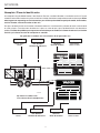 4
4
-
 5
5
-
 6
6
-
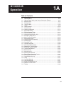 7
7
-
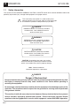 8
8
-
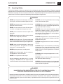 9
9
-
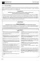 10
10
-
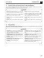 11
11
-
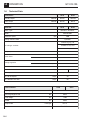 12
12
-
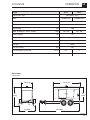 13
13
-
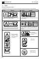 14
14
-
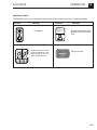 15
15
-
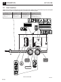 16
16
-
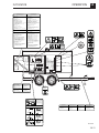 17
17
-
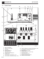 18
18
-
 19
19
-
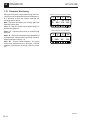 20
20
-
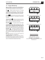 21
21
-
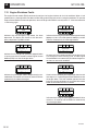 22
22
-
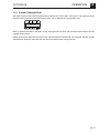 23
23
-
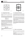 24
24
-
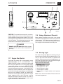 25
25
-
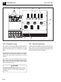 26
26
-
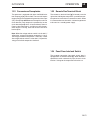 27
27
-
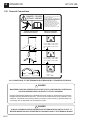 28
28
-
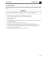 29
29
-
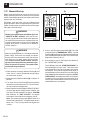 30
30
-
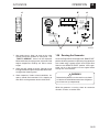 31
31
-
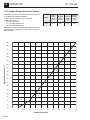 32
32
-
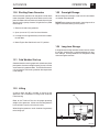 33
33
-
 34
34
-
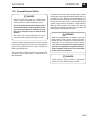 35
35
-
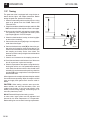 36
36
-
 37
37
-
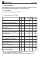 38
38
-
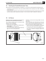 39
39
-
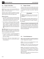 40
40
-
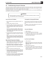 41
41
-
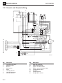 42
42
-
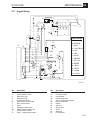 43
43
-
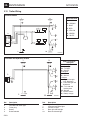 44
44
-
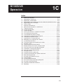 45
45
-
 46
46
-
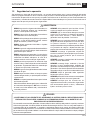 47
47
-
 48
48
-
 49
49
-
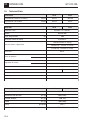 50
50
-
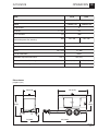 51
51
-
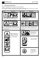 52
52
-
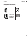 53
53
-
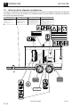 54
54
-
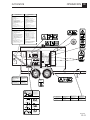 55
55
-
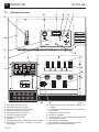 56
56
-
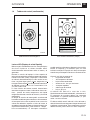 57
57
-
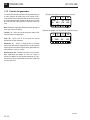 58
58
-
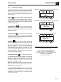 59
59
-
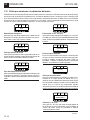 60
60
-
 61
61
-
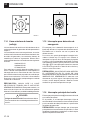 62
62
-
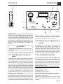 63
63
-
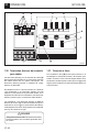 64
64
-
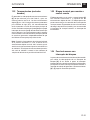 65
65
-
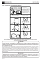 66
66
-
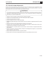 67
67
-
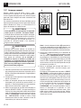 68
68
-
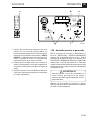 69
69
-
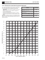 70
70
-
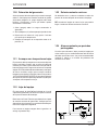 71
71
-
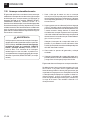 72
72
-
 73
73
-
 74
74
-
 75
75
-
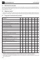 76
76
-
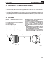 77
77
-
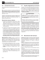 78
78
-
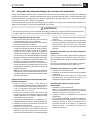 79
79
-
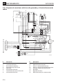 80
80
-
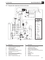 81
81
-
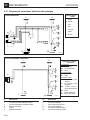 82
82
-
 83
83
-
 84
84


Wacker Neuson G110 Manual de usuario
- Categoría
- Generadores de poder
- Tipo
- Manual de usuario
- Este manual también es adecuado para
En otros idiomas
- English: Wacker Neuson G110 User manual
Documentos relacionados
-
Wacker Neuson g85 Manual de usuario
-
Wacker Neuson G70 Manual de usuario
-
Wacker Neuson MGT1 Manual de usuario
-
-
-
Wacker Neuson G155 Manual de usuario
-
-
-
Wacker Neuson RT820 Manual de usuario
-
