Zoeller 1332-0006 Instrucciones de operación
- Tipo
- Instrucciones de operación

Questions, problems, missing parts? Before returning to your retailer, call our customer
service department at 1-800-584-8089, 7:30 a.m. - 5:00 p.m., EST, Monday - Friday.
024998 B
ATTACH YOUR RECEIPT HERE
Serial Number Purchase Date
IRRIGATION
PUMPS
MODELS #1332-0006, 1333-0006
Zoeller
®
is a registered trademark
of Zoeller Co. All Rights Reserved.
Español p. 24

2
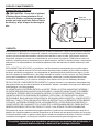
SAFETY INFORMATION
Please read and understand this entire manual before attempting to assemble, operate, or install the
product.
• NOTE: Pumps with the “UL” Mark and pumps with the “US” mark are tested to UL Standard
UL778. CSA certied pumps are certied to CSA Standard C22.2 No. 108. (CUS)
DANGER
ELECTRICAL SHOCK HAZARD.
Always disconnect power source before performing any work on or near the motor or its connected load. If the
power disconnect point is out-of-sight, lock it in the open position and tag it to prevent unexpected application of
power. Failure to do so could result in fatal electrical shock.
ELECTRICAL SHOCK HAZARD.
Do not handle the pump with wet hands or when standing in water as fatal electrical shock could occur.
Disconnect main power before handling unit for ANY REASON!
RISK OF ELECTRIC SHOCK.
These pumps have not been investigated for use in swimming pool areas.
WARNING
ELECTRICAL SHOCK ALERT.
Follow all local electrical and safety codes, as well as the National Electrical Code (NEC) and the Occupational
Safety and Health Act (OSHA).
ELECTRICAL SHOCK ALERT.
Replace damaged or worn wiring cord immediately.
ELECTRICAL SHOCK ALERT.
Do not kink power cable and never allow the cable to come in contact with oil, grease, hot surfaces, or chemicals.
ELECTRICAL SHOCK ALERT.
Unit must be securely and adequately electrically grounded. This can be accomplished by wiring the unit to a
ground metal-clad raceway system or by using a separate ground wire connected to the bare metal of the motor
frame or other suitable means.
CHEMICAL ALERT.
Prop65 Warning for California residents:
WARNING: Cancer and Reproductive Harm - www.P65Warnings.ca.gov
CAUTION
ELECTRICAL SHOCK MAY OCCUR
Protect the power cable from coming in contact with sharp objects.
HOT SURFACE MAY CAUSE BURNS
Be careful when touching the exterior of an operating motor - It may be hot enough to be painful or cause injury.
PRODUCT DAMAGE MAY RESULT
Make certain that the power source conforms to the requirements of your equipment.

3
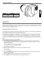
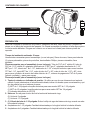
PACKAGE CONTENTS
Description Quantity
Pump 1
Foot Valve 1
Before beginning installation of product, make sure all parts are present. Compare parts with package
contents drawing. If any part is missing or damaged, do not attempt to assemble the product. Contact
customer service for replacement parts.
Estimated Installation Time: 2 hours.
Tools Required for Assembly (not included): Hacksaw, Pipe Wrenches (2), Wire Strippers, Needle-Nose
Pliers, Phillips Screwdriver, Wire Cutters, Adjustable Wrench
Parts Required For Assembly (not included): 2 in. Sched 40 PVC pipe, 1-1/2 in. Sched 40 PVC pipe,
2 in. MPT x 2 in. slip adapter, 1-1/2 in. MPT x 1-1/2 in. slip adapter, 1-1/2 in. pipe tee, 1-1/2 in. slip
x 1-1/4 in. FPT reducer bushing, 1-1/4 in. MPT plug, 2 in. 90º pipe elbow, 1-1/2 in. 90º pipe elbow,
thread tape, 1/4 in. electric wire strain relief, 2-step PVC glue system (primer and sealer), and thread
paste.
Optional Parts For Assembly (not included):
1. Priming Plug with Pressure Gauge: Used instead of a priming plug alone. Helps determine if
the pump is primed, indicates if the pump is operating properly and what kind of pressure is in the
system when operating.
(1) 1-1/4 in. MPT x 1/2 in. FPT reducer bushing
(1) 1/2 in. MPT x 1/4 in. FPT reducer bushing
(1) 100 PSI pressure gauge
2. Unions: Used for easy removal of the pump from the sprinkler system.
(2) 2 in. union
(1) 1-1/2 in. union
3. (1) 1-1/2 in. Ball Valve: Prevents back flow of water from the sprinkler system when the pump is
removed from the system.
4. 1-1/2 in. Couplers: Quantity determined by the total length of pipe used.
5. 2 in. Couplers: Quantity determined by the total length of pipe used.
PREPARATION

4
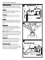
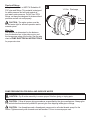
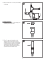
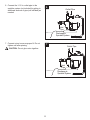
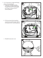
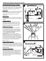
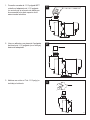
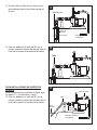
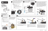
Typical Pump Setup
Typical setups for lawn sprinkler pump systems
include ground water wells (Fig. 1) or surface
water, such as lakes, ponds, or streams. (Fig. 3)
Location
For best performance, the pump must be
located as close to the water source as possible
and protected from the elements.
Ventilation
Ventilation and drainage must be provided to
prevent damage to the motor from heat and
moisture.
Freezing
The pump and all piping must be protected from
freezing. If freezing weather is forecast, drain
pump or remove completely from the sprinkler
system.
Water Supply
The water source must be able to supply
enough water to satisfy the capacity of the pump
and water needs. See performance chart in
section: SPECIFICATIONS.
WARNING: NEVER run pump against a
closed discharge. Doing so can boil water inside
pump causing hazardous pressure in unit, risk of
explosion and possibly scald persons handling
pump. (Fig. 2)
Vertical Lift
Vertical lift is the vertical distance from the
lowest level of the water to the pump intake. The
pump will move water as long as the pump is
within 25 vertical feet of the water source.
Horizontal Distance
The horizontal distance is the horizontal
measurement between the pump inlet and the
water source. This distance may affect the ability
of the pump to operate. If it is over 60 feet, call
customer service at 1-800-584-8089.
GENERAL PUMP INFORMATION
Water Level
25 ft.
max
Vertical
Lift
Outlet
Pipe
Inlet
Pipe
Discharge to
Sprinkler System
60 ft. max.
Inlet pipe to water
Pipe
Support
1
2
Water Level
25 ft.
max
Vertical
Lift
Outlet Pipe
Inlet
Pipe
Discharge to
Sprinkler System
Inlet pipe to water
Pipe
Support
60 ft. max.
Motor Cover
Foot
Valve
3

5
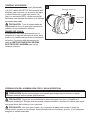
Pipe And Fittings
Use galvanized steel or NSF PW Schedule 40
PVC pipe and fittings. This material is designed
for water pressure and will seal against air
and water under pressure. Do Not Use: DWV
fittings, as these are designed for drains without
pressure and will not seal properly.
CAUTION: The entire system must be
air and water tight for efficient operation and to
maintain prime.
Wire Size:
The wire size is determined by the distance
from the breaker box to the pump motor, and
the horsepower rating of the motor. See the wire
chart in PUMP ELECTRICAL INSTRUCTIONS
for proper wire size.
1-1/2 in. Discharge
2 in.
Suction
4
CAUTION: Dry-t entire assembly to ensure proper t before gluing or taping parts.
CAUTION: Follow all proper gluing procedures as specied by the glue manufacturer. Always glue
in a vertical direction whenever possible to prevent glue from dripping inside pipe or ttings.
CAUTION: Use thread tape and a thread paste compound on all male threads except for the
unions. Tighten securely with a wrench and add another 1/4 turn to ensure proper seal.
PUMP PREPARATION FOR WELL AND SURFACE WATER

6
IL1252
IL1253
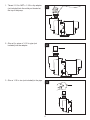
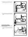
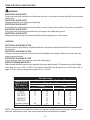
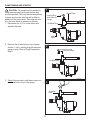
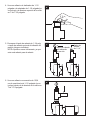
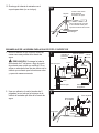
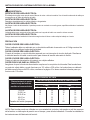
1. Thread 1-1/2 in. MPT x 1-1/2 in. slip adapter
(not included) into the outlet port located at
the top of the pump.
2. Glue a 6 in. piece of 1-1/2 in. pipe (not
included) into the adapter.
3. Glue a 1-1/2 in. tee (not included) to the pipe.
1
3
2
IL1254

7
4
5
6
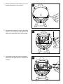
4. Glue a 1-1/2 in. slip x 1-1/4 in. adapter (not
included) to the top opening of the 1-1/2 in.
tee.
5. Thread in a 1-1/4 in. priming plug or optional
priming plug with pressure gauge (neither
included).
NOTE: Hand tighten only, as this will be
removed for priming.
6. Glue another 6 in. section of 1-1/2 in. pipe
(not included) into the opening in the
1-1/2 in. tee.
IL1255
Priming Plug
with Pressure
Gauge
1-1/4 in.
Priming
Plug

8
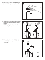
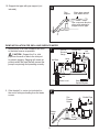
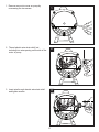
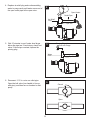
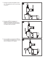
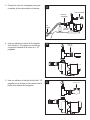
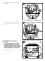
7. Glue the male thread side of a 1-1/2 in. union
(not included) to the pipe.
8. Thread 2 in. MPT x 2 in. slip adapter (not
included) into the inlet port located on the
front of the pump body.
9. Glue an 8 in. section of 2 in. pipe (not
included) into the 2 in. adapter.
7
8
9

9
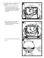
10. Glue one side of a 2 in. union (not included)
to the pipe.
For Well Installations
11. Thread a 2 in. MPT x 2 in. slip adapter (not
included) into the foot valve.
12. Glue 2 in. pipe (not included) into the
adapter. Glue enough sections of pipe
together using 2 in. couplers (not included)
in order for the foot valve to be completely
submerged in water. Be sure inlet pipe
will remain fully submerged at the lowest
expected level of the water source.
10
11
12

10
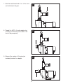
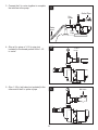
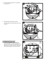
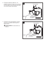
13. Install well seal (not included) in order to
hold the inlet pipe in position in the well.
14. Glue a 90º elbow (not included) when the
inlet pipe is in line with the inlet port of the
pump.
For Surface Water Installations
For surface water installations, follow steps 11
and 12 above and then:
15. Glue a 45º elbow (not included) when the
inlet pipe is in line with the inlet port of the
pump.
IL1261
Water Level
Discharge to
Sprinkler System
Well Seal
Inlet Pipe
Water Level
Discharge to
Sprinkler System
Elbow
Water
Level
Outlet Pipe
Inlet
Pipe
Discharge to
Sprinkler System
Elbow
13
14
15

11
PUMP INSTALLATION FOR WELL AND SURFACE WATER
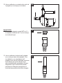
1. Mount pump on a solid foundation as close
to the water source as possible.
CAUTION: Support the 2 in. inlet
pipe from the well or lake to the inlet port
to prevent sagging. Sagging will create air
pockets within the pipe that will prevent the
pump from priming and operating correctly.
2. Glue female 2 in. union (not included) to
the end of inlet pipe leading from the water
source.
Water Level
Discharge to
Sprinkler System
Well Seal
100 PSI
Pressure
Gauge
Priming Plug
Union
Ball
Valve
Outlet
Pipe
Inlet
Pipe
Well
Union
Water
Level
Outlet Pipe
Inlet
Pipe
2 in.
Female
Union
16. Support inlet pipe with pipe support (not
included).
Pipe
support
Slope pipe upward
from water source
Use a concrete block or
other solid material to
support suction pipe
Water level
16
1
2

12
3. Connect the 2 in. union together to complete
the inlet line to the pump.
4. Glue a 6 in. piece of 1-1/2 in. pipe (not
included) to the female portion of the 1-1/2
in. union.
5. Glue 1-1/2 in. ball valve (not included) to the
other end of the 6 in. piece of pipe.
Water
Level
Outlet Pipe
Inlet
Pipe
2 in.
Union
1-1/2 in.
Union
Ball Valve
3
4
5

13
6. Connect the 1-1/2 in. outlet pipe to the
sprinkler system (not included) by gluing in
additional sections of pipe (not included) as
needed.
7. Connect union to ensure proper t. Do not
tighten until after priming.
CAUTION: Do not glue union together.
IL1123
Outlet Pipe
Inlet
Pipe
Discharge to
Sprinkler System
IL1124
Outlet Pipe
Inlet
Pipe
Discharge to
Sprinkler System
6
7

14
PUMP ELECTRICAL INSTRUCTIONS
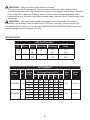
Wire Size Chart
Distance From
Motor To Fuse
Box, Meter or
Electrical Outlet
Minimum Copper Wire Size Chart (Gauge)
Single Phase Motors
1-1/2 HP 2 HP
115 Volt 230 Volt 115 Volt 230 Volt
0-50 Ft.
50-100 Ft.
100-150 Ft.
150-200 Ft.
200-300 Ft.
Fuse Size (Amps)
12
10
8
*
*
20
14
14
12
12
10
15
12
10
8
*
*
20
14
14
12
10
10
15
(*) Not economical to run in 115 V; use 230 V
NOTE: This pump can be used with a variety of controls, including a pump start relay, pressure switch
with tank, and indexing valve. See control manufacturer’s instructions for details.
ELECTRICAL SHOCK ALERT.
Under-size wiring can cause motor failure and even fire. Use proper wire size specified in the wire size
chart below.
ELECTRICAL SHOCK ALERT.
Replace damaged or worn wiring cord immediately.
ELECTRICAL SHOCK ALERT.
Do not kink power cable and never allow the cable to come in contact with oil, grease, hot surfaces, or chemicals.
ELECTRICAL SHOCK ALERT.
The pump must be properly grounded using the proper wire cable with ground.
ELECTRICAL SHOCK ALERT.
Always disconnect pump from electricity before performing any work on the motor.
ELECTRICAL SHOCK MAY OCCUR
All wiring should be performed by a qualified electrician in accordance with the National Electric Code and local
electric codes.
ELECTRICAL SHOCK MAY OCCUR
Connect the pump to a separate electrical circuit with a dedicated circuit breaker. Reference the wire size chart
below for proper fuse size.
ELECTRICAL SHOCK MAY OCCUR
Protect the power cable from coming in contact with sharp objects.
PRODUCT DAMAGE MAY RESULT
Make certain that the power source matches the pump requirements. This pump has a dual voltage
motor and can run on 115 V or 230 V. This pump is wired from the factory to run on 230 volts; refer to
page 16 if you want to change the pump to run on 115 volts.
WARNING
CAUTION

15
A B
L2
L1
IL1271
A B
L2
L1
IL1272
2
3
2. Thread electric wire strain relief (not
included) into wire opening on the side of the
motor of pump.
3. Insert wire through electric wire strain relief
and tighten screws.
1
1. Remove rear motor cover on pump by
unscrewing the two screws.

16
A B
L2
L1
IL1273
4
4. Connect white power lead to L1 and black
power lead to L2.
5. Connect green ground wire to green
grounding screw. Re-install rear motor cover
to pump.
To change from 230 V to 115 V
6. The motor of pump is dual voltage and
can run on either 115 volts or 230 volts. In
general, 230 volts is more economical to run,
and requires a smaller wire size. The pump
is pre-set in the factory to run at 230 volts.
A B
L2
L1
IL1274
A B
L2L1
G R AY
RED
5
6

17
b. Pull the red wire with the female flag
connector from the “B” terminal. Place it
to the right on the L2 terminal spade post.
c. Reinstall the rear motor cover.
A B
L2L1
G R AY
RED
7b
7c
7. For 115 volts service, change the following
wires on the terminal board:
a. Using a pair of needle nose pliers,
pull the gray wire with the female flag
connector from the “B” terminal spade
post. Place it to the left on the “A”
terminal spade post.
A B
L2L1
G R AY
RED
7a

18
PUMP PRIMING AND STARTUP
IL1278
Priming Plug
with Pressure
Gauge
Outlet Pipe
Inlet
Pipe
Air Relief Plug
IL1279
Priming Plug with
Pressure Gauge
Air Relief Plug
IL1280
Air Relief
Hole
1
2
3
CAUTION: All pumps must be primed by
filling the pump cavity with water before they
are first operated. This may take several gallons
of water, as the entire inlet line will be filled in
addition to the pump cavity. The longer the inlet
line, the more water is required for priming.
1. Disconnect the 1-1/2 in. outlet union and
separate the pipe.
2. Remove the air relief plug on top of pump
and the 1-1/4 in. priming plug with pressure
gauge or plug. Refer to Pump Preparation
Step 5.
3. Slowly fill pump cavity until water comes out
of air relief hole on top of the pump.

19
IL1288
Priming Plug with
Pressure Gauge
Water
Level
Pipe Tee
Closed
Open
5
6
5. Wait 10 minutes to see if water level drops
below the pipe tee. If level drops, check foot
valve. If level stays constant, replace the
priming plug.
6. Reconnect 1-1/2 in. union on outlet pipe.
Open the ball valve (turn handle to line up
with pipe), and then turn on breaker to start
pump.
Outlet Pipe
Open Union
Air Relief
Plug
Pipe Tee
4
4. Replace air relief plug and continue adding
water to pump cavity until water comes out of
the open outlet pipe at the open union.

20
IMPORTANT: If the pump fails to prime within five minutes:
7. Turn the power off at the breaker box. Check all pipe connections for leaks, making sure all
connections are water and air tight. Check the inlet pipe for any sagging, making sure the inlet pipe
is in a straight line to the pump. Watch for leaks or a milky color in the discharged water, which
indicates an air leak. Re-prime if necessary, following steps 1 through 6 above. Reset breaker at the
breaker box.
IMPORTANT: If the pump hums instead of pumping or turns off repeatedly, shut pump off
immediately. Check voltage. Pump is wired to run on 230 volts. If the pump cuts out or stops, you
may be attempting to connect to 115 volts. See PUMP ELECTRICAL INSTRUCTIONS to see how to
correctly change the motor voltage to 115 volts.
MOTOR DATA CHART
HP Phase Volts Code Letter Max Amps
Locked Rotor
Amps
1-1/2
1
1
115
230
G
18.0
9.0
72.0
36.0
2
1
1
115
230
G
21.0
10.5
108.0
54.0
PERFORMANCE
Item
Number
HP
Vertical
Lift (FT)
Capacity - U.S. Gallons per Minute
Discharge Pressure (PSI)
Inlet
Pipe
Outlet
Pipe
15 20 25 30 35 40
1332-0006 1-1/2
10 66 58 53 42 32 10
2 in. 1-1/2 in.
15 62 57 47 38 25 7
20 54 52 42 31 13 3
25 40 38 36 23 12 0
1333-0006 2
10 67 62 56 49 39 27
2 in. 1-1/2 in.
15 63 59 52 44 34 25
20 59 56 49 40 29 9
25 37 36 35 31 18 5
SPECIFICATIONS

21
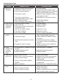
TROUBLESHOOTING
Problem Possible Cause Corrective Action
A. Little or no
discharge
1. Casing not initially filled with water 1. Fill pump casing
2. Vertical lift too high or too long 2. Move pump closer to water source
3. Hole or air leak in inlet line 3. Repair or replace inlet line. Use thread
tape and pipe sealing compound
4. Foot valve too small 4. Match foot valve to piping or install one
size larger foot valve.
5. Foot valve or inlet line not
submerged deep enough in water
5. Submerge foot valve lower in water
6. Motor wired incorrectly 6. Check wiring diagram
7. Inlet or outlet line valves closed 7. Open valves
B. Pump will not
deliver water
or develop
pressure
1. No priming water in casing 1. Fill pump casing
2. Leak in inlet line 2. Repair or replace
3. Outlet line is closed and priming air
has nowhere to go
3. Open ball valve
4. Inlet line (or valve) is closed 4. Open line or valve
5. Foot valve is leaking 5. Replace foot valve
6. Inlet screen clogged 6. Clean or replace inlet screen
C. Loss of
suction
1. Hole or air leak in inlet line 1. Repair or replace inlet line. Use thread
tape and pipe sealing compound
2. Vertical lift too high 2. Reduce vertical lift, install foot valve
and prime
3. Insufficient inlet pressure or suction
head
3. Increase inlet pressure by adding
more water to tank or increasing back
pressure
4. Clogged foot valve or strainer 4. Inspect foot valve and/or strainer for
debris and remove
D. Pump
vibrates and/
or makes
excessive
noise
1. Mounting plate or foundation not rigid
enough
1. Reinforce plate or foundation
2. Foreign material in pump 2. Disassemble pump and clean
3. Impeller damaged 3. Replace impeller
E. Pump will not
start or run
1. Motor wired incorrectly 1. Check wiring diagram
2. Blown fuse or open circuit breaker 2. Replace fuse or close circuit breaker
3. Loose or broken wiring 3. Tighten connections and replace
broken wiring
4. Stone or foreign object lodged in
impeller
4. Disassemble pump and remove
foreign object
5. Motor overheated 5. Allow unit to cool, restart after cooling
F. Pump loses
prime
1. Clogged foot valve or strainer 1. Inspect foot valve and/or strainer for
debris, and remove.
2. Worn or broken foot valve 2. Inspect and replace
3. Hole or air leak in inlet line 3. Repair or replace inlet line. Use thread
tape and pipe sealing compound

22
CARE AND MAINTENANCE
WARRANTY
This product is warranted for two years from the date of manufacture. Subject to the conditions hereinafter set
forth, the manufacturer will repair or replace to the original consumer any portion of the product which proves
defective due to defective materials or workmanship. To obtain warranty service, contact the dealer from whom
the product was purchased. The manufacturer retains the sole right and option to determine whether to repair
or replace defective equipment, parts, or components. Damage due to conditions beyond the control of the
manufacturer is not covered by this warranty.
THIS WARRANTY WILL NOT APPLY: (a) To defects or malfunctions resulting from failure to properly install,
operate, or maintain the unit in accordance with printed instructions provided; (b) to failures resulting from abuse,
accident, or negligence, or use of inappropriate chemicals or additives in the water; (c) to normal maintenance
services and the parts used in connection with such service; (d) to units which are not installed in accordance
with normal applicable local codes, ordinances, and good trade practices; and (e) if the unit is used for purposes
other than for what it was designed and manufactured.
RETURN OF WARRANTED COMPONENTS: Any item to be repaired or replaced under this warranty must be
returned to the manufacturer at Kendallville, Indiana or such other place as the manufacturer may designate,
freight prepaid.
THE WARRANTY PROVIDED HEREIN IS IN LIEU OF ALL OTHER EXPRESS WARRANTIES, AND MAY
NOT BE EXTENDED OR MODIFIED BY ANYONE. ANY IMPLIED WARRANTIES SHALL BE LIMITED TO
THE PERIOD OF THE LIMITED WARRANTY AND THEREAFTER ALL SUCH IMPLIED WARRANTIES ARE
DISCLAIMED AND EXCLUDED. THE MANUFACTURER SHALL NOT, UNDER ANY CIRCUMSTANCES, BE
LIABLE FOR INCIDENTAL, CONSEQUENTIAL OR SPECIAL DAMAGES, SUCH AS, BUT NOT LIMITED TO
DAMAGE TO, OR LOSS OF, OTHER PROPERTY OR EQUIPMENT, LOSS OF PROFITS, INCONVENIENCE,
OR OTHER INCIDENTAL OR CONSEQUENTIAL DAMAGES OF ANY TYPE OR NATURE. THE LIABILITY
OF THE MANUFACTURER SHALL NOT EXCEED THE PRICE OF THE PRODUCT UPON WHICH SUCH
LIABILITY IS BASED.
This warranty gives you specic legal rights, and you may have other rights which vary from state to state.
Some states do not allow limitations on duration of implied warranties or exclusion of incidental or consequential
damages, so the above limitations may not apply to you.
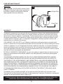
Winterizing
CAUTION: Drain the entire system if there
is danger of freezing. A drain plug is provided at
the bottom of pump for this purpose. Remove
drain plug then loosen air relief plug.
Drain Plug
Air Relief Plug
1
In those instances where damages are incurred as a result of an alleged pump failure, the
Homeowner must retain possession of the pump for investigation purposes.

23
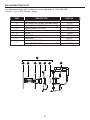
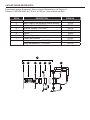
REPLACEMENT PARTS LIST
For replacement parts, call our customer service department at 1-800-584-8089,
7:30 a.m. - 5 p.m., EST, Monday - Friday..
IF GEDC H
J
PART DESCRIPTION PART NO.
C Ring, Square Cut 132429
D Seal, Rotary and Ceramic (includes Spring) 131100
E Impeller (Model 1332-0006) 021280
E Impeller (Model 1333-0006) 134138
F Diffuser Insert 134240
G Diffuser 132425
H Rubber Diffuser 132428
I Pump Body 023115
J
Rebuild Kit 1332-0006 023704
Rebuild Kit 1333-0006 023705

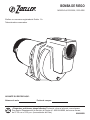
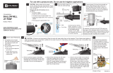
BOMBA DE RIEGO
MODELO #1332-0006, 1333-0006
¿Preguntas, problemas, piezas faltantes? Antes de volver a la tienda, comuníquese
con nuestro Departamento de Servicio al Cliente al 1-800-584-8089, de lunes a viernes,
de 07:30 a.m. a 5:00 p.m. (hora estándar del Este).
024998S B
ADJUNTE SU RECIBO AQUÍ:
Número de serie Fecha de compra
Zoeller
®
es una marca registrada de Zoeller Co.
Todos derechos reservados.
Translation Code for 10/11 Update: LB597562 - Reference this code when English is
updated again.
Translation code for 02/12 update: Validation code LB733240

INFORMACIÓN DE SEGURIDAD
RIESGO DE DESCARGA ELÉCTRICA.
Siempre desconecte la fuente de alimentación antes de llevar a cabo cualquier trabajo en el motor
o cerca de éste, o en su carga conectada. Si el punto de desconexión de la alimentación está
fuera de la vista, fíjelo en la posición abierta y etiquételo para evitar una aplicación de alimentación
inesperada. El incumplimiento de dicho paso podría provocar una descarga eléctrica fatal.
RIESGO DE DESCARGA ELÉCTRICA.
No manipule la bomba con las manos húmedas ni cuando esté parado en el agua, ya que podría
ocurrir una descarga eléctrica fatal. SIN IMPORTAR EL MOTIVO, desconecte la alimentación
principal antes de manipular la unidad.
RIESGO DE DESCARGA ELÉCTRICA.
No se ha vericado el uso de estas bombas en piscinas.
ALERTA DE DESCARGA ELÉCTRICA.
Siga todos los códigos locales eléctricos y de seguridad, además del Código nacional de electricidad
(NEC, por sus siglas en inglés) y el de la Administración de Salud y Seguridad Ocupacional (OSHA,
por sus siglas en inglés).
ALERTA DE DESCARGA ELÉCTRICA.
Reemplace inmediatamente los cables dañados o desgastados.
ALERTA DE DESCARGA ELÉCTRICA.
No pliegue el cable de alimentación ni permita que entre en contacto con aceite, grasa, supercies
calientes ni sustancias químicas.
ALERTA DE DESCARGA ELÉCTRICA.
La unidad debe contar con una puesta eléctrica a tierra segura y apropiada. Esto se puede lograr
conectando el cableado de la unidad a un sistema de canaletas con revestimiento metálico y puesta
a tierra o usando un conductor de tierra separado conectado al metal sin revestir de la estructura del
motor u otros medios adecuados.
ALERTA DE PRODUCTO QUÍMICO.
Advertencia de Proposición 65 para residentes de California:
Advertencia: Cáncer y Daño Reproductivo – www.P65Warnings.ca.go
PUEDE OCURRIR DESCARGA ELÉCTRICA
Proteja el cable de alimentación del contacto con objetos alados.
LA SUPERFICIE CALIENTE PUEDE CAUSAR QUEMADURAS
Sea cuidadoso al tocar el exterior de un motor en funcionamiento, ya que puede estar lo
sucientemente caliente como para causar dolor o alguna lesión.
PUEDE PROVOCAR DAÑO AL PRODUCTO
Asegúrese de que la fuente de energía cumpla los requisitos de su equipo.
Lea y comprenda completamente este manual antes de intentar ensamblar, usar o instalar el
producto.
• NOTA: Las bombas con la marca “UL” y las bombas con la marca “US” son probadas para
cumplir los estándares de UL UL778. Las bombas cericadas por CSA están certicadas para
cumplir los estándares de CSA C22.2 No. 108. (CUS)
PELIGRO
ADVERTENCIA
PRECAUCIÓN

CONTENIDO DEL PAQUETE
Descripción Cantidad
Bomba 1
Válvula de pie 1
Antes de comenzar la instalación del producto, asegúrese de tener todas las piezas. Compare las
piezas con el dibujo del contenido del paquete. No intente ensamblar el producto si falta alguna pieza
o si éstas están dañadas. Póngase en contacto con el servicio al cliente para obtener piezas de
repuesto.
Tiempo de instalación estimado: 2 horas.
Herramientas necesarias para el ensamblaje: (no se incluyen): Sierra de mano, llaves para tuberías
(2), pinzas pelacables, pinzas de punta na, destornillador Phillips, pinzas cortacables, llave
ajustable.
Piezas necesarias para el ensamblaje (no se incluyen): Tubo de PVC de 2” cédula 40, tubo de
PVC de 1-1/2” cédula 40, adaptador deslizante de 2” MPT por 2”, adaptador deslizante de 1-1/2”
MPT por 1-1/2”, tubería en T de 1-1/2”, deslizador de 1-1/2” x boquilla reductora para rosca hembra
FPT de 1-1/4”, tapón MPT de 1-1/4”, codo de tubo de 2” y 90º, codo de tubo de 1-1/2” y 90º, cinta
para roscas, aliviador de tensión del cable eléctrico de ¼”, sistema de pegamento PVC de 2 pasos
(cebado y sellado), y pasta para roscas.
Piezas opcionales para el ensamblaje (no se incluyen)
1. Tapón de cebado con indicador de presión: Se utiliza en vez de usar únicamente un tapón de
cebado. Ayuda a determinar si la bomba está cebada, indica si la bomba opera correctamente y qué
tipo de presión hay en el sistema al operar.
(1) MPT de 1-1/4 pulgada x boquilla reductora para rosca macho NPT de 1-1/2 pulgada
(1) MPT de 1/2 pulgada x boquilla reductora para rosca macho NPT de 1/4 pulgada
(1) Indicador de presión de 100 PSI
2. Uniones: Se usa para el retiro fácil de la bomba del sistema de riego.
(2) Unión de 2 pulgadas
(1) Unión de 1-1/2 pulgada
3. (1) Válvula de bola de 1-1/2 pulgada: Evita el reflujo de agua del sistema de riego cuando se retira
la bomba del sistema.
4. Acopladores de 1-1/2 pulgada: Cantidad determinada por la longitud total de la tubería utilizada.
5. Acopladores de 2 pulgadas: Cantidad determinada por la longitud total de la tubería utilizada.
PREPARACIÓN

INFORMACIÓN GENERAL ACERCA DE LA BOMBA
CONFIGURACIÓN TÍPICA DE LA BOMBA
Las conguraciones típicas para los sistemas
de bomba de riego para césped incluyen pozos
de agua del subsuelo (Fig. 1) o agua supercial,
como lagos, estanques o arroyos. (Fig. 3)
UBICACIÓN
La bomba se debe colocar lo más cerca posible
de la fuente de agua y debe estar protegida
de los elementos para obtener un mejor
rendimiento.
VENTILACIÓN
Se debe proporcionar ventilación y drenaje para
evitar daños al motor producto de la humedad y
el calor.
CONGELAMIENTO
La bomba y todas las tuberías deben estar
protegidas de temperaturas muy frías. Si se
pronostica clima muy frío, drene la bomba o
retírela por completo del sistema de riego.
SUMINISTRO DE AGUA
La fuente de agua debe tener la capacidad
de suministrar agua suciente para satisfacer
la capacidad de la bomba y las necesidades
de agua. Consulte la tabla de desempeño en
sección: ESPECIFICACIONES.
ADVERTENCIA: NUNCA haga funcionar la
bomba contra una válvula de descarga cerrada.
El hacerlo puede hervir el agua al interior de la
bomba, lo cual ocasionará una presión peligrosa
en la unidad, riesgo de explosión y quemaduras
en las personas que estén manipulando la
bomba. (Fig. 2)
ELEVACIÓN DE SUCCIÓN
La elevación de succión es la distancia vertical
desde el nivel más bajo de agua hasta la entrada
de la bomba. La bomba moverá el agua siempre
y cuando se encuentre a 25 pies en vertical de la
fuente de agua.
DISTANCIA HORIZONTAL
La distancia horizontal es la medida horizontal
entre la bomba de succión y la fuente de agua.
La distancia puede afectar la capacidad de
operación de la bomba. Si mide más de 18,29
metros, llame al fabricante al 1-800-584-8089
para obtener ayuda.
Nivel de agua
7,62 cm
máx.
Elevación
vertical
Tubo de salida
Tubo de
entrada
Descarga al sistema
de regadores
18,29 m máx.
Apoyo de la tubería
Tubería de entrada al agua
1
2
Nivel de agua
7,62 cm
máx.
Elevación
vertical
Tubo de salida
Tubo de
entrada
Descarga al sistema
de regadores
Tubería de entrada al agua
Apoyo de la tubería
18,29 m máx.
Cubierta
del motor
Válvula
de pie
3

TUBERÍA Y ACCESORIOS
Use tubería y accesorios de acero galvanizado
o de PVC cédula 40 NSF PW. Este material está
diseñado para funcionar con la presión del agua
y sellará contra aire y agua bajo presión. No
usar: Los accesorios DWV, ya que estos están
diseñados para drenajes sin presión y no sellaran
de manera adecuada.
PRECAUCIÓN: Todo el sistema debe ser
impermeable al aire y al agua para mantener el
cebado y un funcionamiento eciente.
TAMAÑO DEL CABLE:
El tamaño del cable está determinado por la
distancia de la caja del interruptor al motor de la
bomba y los caballos de fuerza de la clasicación
del motor. Consulte la tabla de tamaños de
cable en INSTRUCCIONES DEL SISTEMA
ELÉCTRICO DE LA BOMBA para ver los
tamaños correctos.
Descarga de 3,81 cm
Succión de
5 cm
4
PRECAUCIÓN: Ajuste completamente el ensamble para asegurarse de obtener un ajuste
adecuado antes de unir las piezas denitivamente.
PRECAUCIÓN: Siga todos los procedimientos adecuados para unir como lo especica el
fabricante de adhesivo. Siempre que sea posible coloque el adhesivo en dirección vertical para evitar
que gotee dentro de la tubería o los conectores.
PRECAUCIÓN: Use cinta para roscas y un compuesto de pasta para roscas en todas las
roscas macho, excepto en las uniones. Apriete rmemente con una llave y gire otro ¼ de vuelta para
asegurar un sellado adecuado.
PREPARACIÓN DE LA BOMBA PARA POZO Y AGUA SUPERFICIAL

IL1252
IL1253
IL1254
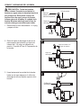
1. Conexión roscada de 1-1/2 pulgada MPT
x deslice el adaptador de 1-1/2 pulgada
(no se incluye) en el puerto de salida que
se encuentra en la parte superior de la
estructura de la bomba.
2. Una con adhesivo una pieza de 6 pulgadas
de tubería de 1-1/2 pulgada (no se incluye)
dentro del adaptador.
3. Adhiera una unión en T de 1-1/2 pulg (no
incluida) a la tubería.
1
3
2

4
5
6
4. Una con adhesivo el deslizador de 1-1/2
pulgada x el adaptador de 1-1/4 pulgada (no
se incluye) a la abertura superior de la unión
en T de 1-1/2 pulgada.
5. Enrosque el tapón de cebado de 1-1/4 pulg
o tapón de cebado opcional al indicador de
presión (ninguno incluidos).
NOTA: Apriete a mano únicamente, ya que
esto será retirado para el cebado.
6. Una con adhesivo una sección de 15,24
cm de una tubería de 1-1/2 pulgada (no se
incluye) dentro de la abertura en la unión en
T de 1-1/2 pulgada.
IL1255
Tapón de cebado
con indicador
de presión
Tapón de
cebado
de 1-1/4”

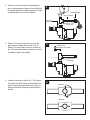
7. Enrosque el costado del adaptador macho
de 1-1/2 pulgada de la unión (no se incluye)
a la tubería.
8. Enrosque el MPT de 2 pulgadas x 2
pulgadas del adaptador deslizante (no se
incluye) en el puerto de entrada localizado
en la parte frontal de la bomba.
9. Una con adhesivo una sección de 20,32 cm
de una tubería de 2 pulgadas (no se incluye)
dentro del adaptador de 2 pulgada.
7
8
9

10. Una con adhesivo un costado de la unión de
2 pulgada (no se incluye) en la tubería
PARA POZOS
11. Enrosque el adaptador macho MPT de 2” x
el adaptador deslizante de 2” (no se incluye)
en la válvula de pie.
12. Una con adhesivo la tubería de 2 pulgada
(no se incluye) dentro del adaptador. Una
con adhesivo y con acopladores de 2
pulgada (no se incluye) suficientes secciones
de la tubería para que la válvula de pie
esté completamente sumergida en el agua.
Asegúrese de que la tubería de entrada
permanezca totalmente sumergida en el
nivel más bajo posible de la fuente de agua.
10
11
12

13. Coloque bien el sello (no se incluye) para
que sostenga bien la tubería de entrada en
el pozo.
14. Una con adhesivo un codo de 90º (no se
incluye) cuando la tubería de entrada esté en
línea con el puerto de entrada de la bomba.
PARA INSTALACIONES EN SUPERFICIE
DE AGUA
Para instalaciones en supercie de agua, siga
los pasos 11 y 12 anteriores y luego:
15. Una con adhesivo un codo de 45º (no se
incluye) cuando la tubería de entrada esté en
línea con el puerto de entrada de la bomba.
IL1261
Nivel de agua
Descarga al sistema
de regadores
Sello del pozo
Tubo de
entrada
Nivel de agua
Descarga al sistema
de regadores
Codo
Nivel
de agua
Tubo de salida
Tubo de
entrada
Descarga al sistema
de regadores
Codo
13
14
15

ENSAMBLAJE DE LA BOMBA PARA AGUA DE POZO Y SUPERFICIE
1. Monte la bomba en un cimiento sólido tan
cerca como sea posible de la fuente de
agua.
PRECAUCIÓN: Sostenga la tubería
de entrada de 2” del pozo o lago al puerto
de entrada para evitar que se aoje. Si se
aoja se crearán bolsas de aire dentro de la
tubería que evitarán que la bomba se cebe
y opere de manera correcta.
2. Una con adhesivo la unión hembra de 2
pulgadas (no se incluye) al extremo de la
tubería de entrada que sale de la fuente de
agua.
Nivel de agua
Descarga al sistema
de regadores
Sello para pozo
Indicador de
presión de
100 PSI
Tapón de cebado
Unión
Válvula
de bola
Tubo
de salida
Tubo de
entrada
Pozo
Unión
Nivel de agua
Tubo de salida
Tubo de
entrada
Unión hembra
de 2 pulgadas
16. Sostenga la tubería de entrada con el
soporte para ésta (no se incluye).
Soporte
de tubo
Incline el tubo hacia
arriba desde el
suministro de agua
Use un bloque de concreto
u otro material sólido para
soportar la tubería de succión
Nivel de agua
16
1
2

3. Conecte la unión de 2 pulgadas junto para
completar la línea de entrada a la bomba.
4. Una con adhesivo la unión de 6 pulgadas
de la tubería 1-1/2 pulgada (no se incluye)
a la porción hembra de la unión de 1-1/2
pulgadas.
5. Una con adhesivo la válvula de bola de 1-1/2
pulgada (no se incluye) al otro extremo de la
pieza de la tubería de 6 pulgadas.
Nivel
de agua
Tubo de salida
Tubo de
entrada
Unión de
2 pulgadas
Unión de
2 pulgadas
Válvula de bola
3
4
5

6. Conecte la tubería de salida de 1-1/2
pulgada al sistema de riego (no se incluye) al
unir con adhesivo las secciones adicionales
de la tubería según sea necesario.
7. Conecte la unión para asegurar un ajuste
adecuado. No apriete hasta después de
haber cebado.
PRECAUCIÓN: No una la unión con
adhesivo.
IL1123
Tubo de salida
Tubo de
entrada
Descarga al sistema
de regadores
IL1124
Tubo de salida
Tubo de
entrada
Descarga al sistema
de regadores
6
7

INSTRUCCIONES DEL SISTEMA ELÉCTRICO DE LA BOMBA
PUEDE OCURRIR DESCARGA ELÉCTRICA
Todo el cableado debe ser realizado por un electricista calicado de acuerdo con el Código nacional de
electricidad y los códigos locales de electricidad.
PUEDE OCURRIR DESCARGA ELÉCTRICA
Conecte la bomba a un circuito eléctrico separado con un interruptor de circuito dedicado. Remítase a
la tabla de tamaño del cable a continuación para obtener el tamaño adecuado de fusible.
PUEDE OCURRIR DESCARGA ELÉCTRICA
Proteja el cable de alimentación del contacto con objetos alados.
PUEDE PROVOCAR DAÑO AL PRODUCTO
Asegúrese de que la fuente de alimentación cumpla con los requisitos de la bomba. Esta bomba tiene
un motor de voltaje doble y puede funcionar con 115 voltios o 230 voltios. La bomba tiene un cableado
de fábrica que funciona con 230 voltios; remítase a la página 16 si desea cambiar la bomba para que
funcione con 115 voltios.
ALERTA DE DESCARGA ELÉCTRICA.
El cableado de tamaño menor puede causar fallas en el motor e incluso incendios. Use el tamaño adecuado de cable que
se especica en la Tabla de tamaños del cable.
ALERTA DE DESCARGA ELÉCTRICA.
Reemplace inmediatamente los cables dañados o desgastados.
ALERTA DE DESCARGA ELÉCTRICA.
No pliegue el cable de alimentación ni permita que entre en contacto con aceite, grasa, supercies calientes ni sustancias
químicas.
ALERTA DE DESCARGA ELÉCTRICA.
La bomba debe tener una puesta a tierra adecuada con la ayuda del cable con conexión a tierra correcto.
ALERTA DE DESCARGA ELÉCTRICA.
Siempre desconecte la bomba de la fuente de energía antes de llevar a cabo cualquier trabajo en el motor.
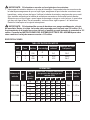
NOTA: Esta bomba puede ser utilizada con una variedad de controles, incluyendo un relé de arranque
de la bomba, un interruptor de presión con el tanque y una válvula indicadora. Consulte los detalles en
las instrucciones del fabricante del control.
Tabla de tamaños del cable
Distancia desde el motor
hasta la caja de fusibles,
medidor o tomacorrientes
Tabla de tamaños de los cables de cobre (calibre)
Motores de fase única
1,5 HP 2 HP
115 voltios 230 voltios 115 voltios 230 voltios
0-15 m
15-30,5 m
30,5-46 m
46-61 m
61-91 m
Tamaño del fusible (amperes)
12
10
8
*
*
20
14
14
12
12
10
15
12
10
8
*
*
20
14
14
12
10
10
15
(*) No es rentable para funcionar en 115 vatios; use 230 vatios
ADVERTENCIA
PRECAUCIÓN

A B
L2
L1
IL1271
A B
L2
L1
IL1272
2
3
2. Enrosque el aliviador de tensión del cable
eléctrico (no se incluye) en la abertura del
cable del costado del motor de la bomba.
3. Introduzca el cable a través del aliviador
de tensión del cable eléctrico y apriete los
tornillos.
1
1. Quite la cubierta posterior del motor en la
bomba retirando los dos tornillos.

A B
L2
L1
IL1273
4
4. Conecte el cable blanco a L1 y el cable
negro a L2.
5. Conecte el conductor de tierra verde al
tornillo verde de puesta a tierra. Vuelva a
instalar
PARA CAMBIAR DE 230 VOLTIOS A
115 VOLTIOS
6. El motor de la bomba es de voltaje doble
y puede funcionar ya sea con 115 ó con
230 voltios. En general, es más económico
cuando funciona con 230 voltios y necesita
cable de menor tamaño. La bomba está
predeterminada de fábrica para funcionar
con 230 voltios.
A B
L2
L1
IL1274
A B
L2L1
GRIS
ROJO
5
6

b. Jale el cable rojo con el conector de
bandera hembra del terminal “B”.
Colóquelo a la derecha en el poste de
paleta del terminal L2.
c. Vuelva a instalar la cubierta posterior del
motor.
A B
L2L1
GRIS
ROJO
7b
7c
7. Para que funcione con 115 voltios, cambie
los siguientes cables en el tablero de
terminales.
a. Con la ayuda de un par de pinzas de
punta fina, jale el cable gris con el
conector de bandera hembra del poste
de paleta del terminal “B”. Colóquelo a
la izquierda en el poste de paleta del
terminal “A”.
A B
L2L1
GRIS
ROJO
7a

CEBADO Y ARRANQUE DE LA BOMBA
IL1278
Tapón de
cebado con
indicador de presión
Tubo de salida
Tubo de
entrada
Tapón de
descarga de aire
IL1279
Tapón de cebado con
indicador de presión
Tapón de
descarga de aire
IL1280
Oricio de
descarga de aire
1
2
3
PRECAUCIÓN: Todas las bombas
deben cebarse llenando la cavidad de la
bomba con agua antes de hacerlas funcionar
por primera vez. Esto puede requerir de
muchos litros de agua, porque se llenará
la línea entera de entrada y la cavidad de la
bomba. Mientras más larga sea la línea de
entrada, más agua necesitará para cebar.
1. Desconecte la unión de salida de 1-1/2 pulg
y separe el tubo.
2. Retire el tapón de descarga de aire en la
parte superior de la bomba y el tapón de
cebado de 1-1/4 pulg con indicador de
presión. Consulte el Paso 5: Preparación de
la bomba.
3. Llene lentamente la cavidad de la bomba
hasta que el agua salga por el orificio de
descarga de aire en la parte superior de la
bomba.

IL1288
Tapón de
cebado con
indicador de presión
Unión T de
la tubería
Cerrado
Abierta
5
6
5. Espere 10 minutos para ver si el nivel de
agua cae por debajo de la unión T de la
tubería. Si el nivel cae, revise la válvula de
pie. Si el nivel permanece constante, vuelva
a instalar el tapón de cebado.
6. Vuelva a conectar la unión de 1-1/2 pulg en
la tubería de salida. Abra la válvula de bola
(gire la manija para alinearla con el tubo) y
luego encienda el interruptor para iniciar la
bomba.
Tubo de salida
Unión abierta
Tapón de
descarga de aire
Unión T de
la tubería
4
4. Vuelva a colocar el tapón de descarga de
aire y siga agregando agua en la cavidad de
la bomba hasta que el agua salga por el tubo
de salida abierto en la unión abierta.

IMPORTANTE: Si la bomba no se ceba en los siguientes cinco minutos:
7. Interrumpa el suministro eléctrico en la caja del interruptor. Compruebe todas las conexiones de
la tubería para asegurarse de que no haya fugas, asegúrese de que todas las conexiones sean
herméticas y eviten el paso del agua. Verifique la tubería de entrada y asegúrese de que no esté
floja, también verifique que la tubería de entrada se encuentre en línea recta hacia la bomba.
Supervise que no haya fugas o que el agua de descarga no tenga un color lechoso, lo que indica
que hay una fuga de aire. De ser necesario, vuelva a cebar, siga los pasos 1 al 6 anteriores.
Reinicie el interruptor en la caja de interruptores.
IMPORTANTE: Si la bomba silba en vez de bombear o se apaga repetidamente, ciérrela
de inmediato. Revise el voltaje. La bomba está preparada para funcionar con 230 voltios. Si el
funcionamiento de la bomba se corta o detiene, es posible que esté tratando de conectarla a 115
voltios. Consulte las INSTRUCCIONES DEL SISTEMA ELÉCTRICO DE LA BOMBA para saber
cómo cambiar el voltaje de manera correcta a 115 voltios.
ESPECIFICACIONES
TABLA DE DATOS DEL MOTOR
HP Fase Voltios Letra código
Amperaje
máximo
Amperaje del rotor
bloqueado
1-1/2
1
1
115
230
G
18.0
9.0
72.0
36.0
2
1
1
115
230
G
21.0
10.5
108.0
54.0
DESEMPEÑO
Número de
artículo
HP
Elevación
de
succión
(pies)
Capacidad: Galones americanos
por presión de descarga por
minute (PSI)
Tubo de
entrada
Tubo de
salida
15 20 25 30 35 40
1332-0006 1-1/2
10 66 58 53 42 32 10
2 in. 1-1/2 in.
15 62 57 47 38 25 7
20 54 52 42 31 13 3
25 40 38 36 23 12 0
1333-0006 2
10 67 62 56 49 39 27
2 in. 1-1/2 in.
15 63 59 52 44 34 25
20 59 56 49 40 29 9
25 37 36 35 31 18 5

LOCALIZACIÓN Y SOLUCIÓN DE PROBLEMAS
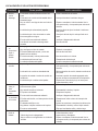
Problema Causa posible Acción correctiva
A. Mínima
o nula
descarga
1. El entubado no está inicialmente relleno con
agua
1. Llene el entubado de la bomba
2. La elevación de succión está demasiado alta o
demasiado larga
2. Acerque la bomba al suministro de agua
3. Hay un oricio o una fuga de aire en el tubo de
succión
3. Repare o reemplace el tubo de entrada. Use la
cinta para roscas y el compuesto para uniones de
tuberías
4. La válvula de pie es demasiado pequeña 4. Ajuste la válvula de pie a la tubería o instale una
más grande.
5. La válvula de pie o tubo de entrada no están
bien sumergidos en el agua
5. Sumerja la válvula de pie lo más profundo en el
agua
6. El motor está incorrectamente cableado. 6. Verique el diagrama del cableado
7. Las válvulas de entrada o descarga están
cerradas
7. Abra las válvulas
B. La bomba
no
proporciona
agua ni
genera
presión
1. No hay agua del cebado en el entubado 1. Llene el entubado de la bomba
2. Hay una fuga en el tubo de entrada 2. Repárelo o reemplácelo
3. El tubo de salida está cerrado, y el aire del
cebado no tiene dónde ir
3. Abra la válvula de bola
4. El tubo de entrada (o válvula) está cerrado 4. Abra el suministro o la válvula
5. La válvula de pie tiene una fuga 5. Reemplace la válvula de pie
6. La malla de entrada está tapada 6. Limpie o reemplace la malla de entrada
C. Pérdida de
succión
1. Hay una fuga de aire en el tubo de entrada 1. Repare o reemplace el tubo de entrada. Use la
cinta para roscas y el compuesto para uniones de
tuberías
2. La elevación de succión es demasiado alta 2. Baje la elevación de succión, instale una válvula de
pie y cebe
3. La presión de entrada o la altura de succión es
insuciente
3. Aumente la presión de entrada agregando más
agua en el tanque o aumentando la contrapresión
4. La válvula de pie o colador están tapados 4. Inspeccione la válvula de pie y/o el tensor para
buscar desechos y retire.
D. La bomba
vibra y/o
hace
demasiado
ruido
1. La placa de montaje o base no están lo
sucientemente rígidas
1. Refuerce la placa o los cimientos
2. Hay material extraño en la bomba 2. Desensamble la bomba y límpiela
3. El impulsor está dañado 3. Remplace el impulsor
E. La bomba
no enciende
ni funciona
1. El motor está incorrectamente cableado. 1. Verique el diagrama del cableado
2. El fusible está fundido, o el interruptor de circuito
está abierto
2. Reemplace el fusible o cierre el interruptor del
circuito
3. El cableado está ojo o roto 3. Apriete las conexiones, reemplace los cables rotos
4. Hay piedras u objetos extraños en el impulsor 4. Desensamble la bomba y retire el objeto extraño
5. El motor se sobrecalentó 5. Deje que la unidad se enfríe y reinicie luego
F. La bomba
pierde el
cebado
1. La válvula de pie o colador están tapados
1. Inspeccione la válvula de pie y/o el tensor para
buscar desechos y retire.
2. Válvula de pie rota o desgastada.
2. Inspeccione y reemplace.
3. Hay un oricio o una fuga de aire en el tubo de
entrada
3.
Repare o reemplace el tubo de entrada. Use la
cinta para roscas y el compuesto para uniones de
tuberías

GARANTÍA
Este producto se garantiza por dos años a partir de la fecha de fabricación. Sujeto a las condiciones indicadas
a continuación, el fabricante se compromete a reparar o reemplazar al consumidor original cualquier parte del
producto que resulte defectuosa debido a defectos de materiales o mano de obra. Para obtener el servicio
de garantía, póngase en contacto con el distribuidor al que le compró el producto. El fabricante se reserva el
derecho y la opción exclusivos de determinar si se deben reparar o sustituir los equipos, piezas o componentes
defectuosos. Los daños debidos a circunstancias ajenas al control del fabricante no están cubiertos por esta
garantía.
ESTA GARANTÍA NO APLICARÁ: (a) a defectos o mal funcionamiento ocasionados por no instalar, operar
o mantener la unidad de acuerdo con las instrucciones impresas proporcionadas, (b) a los fallos resultantes
del abuso, accidentes o negligencia o uso inapropiado de productos químicos o aditivos en el agua, (c) a los
servicios normales de mantenimiento y las piezas utilizadas en relación con dicho servicio; (d) a las unidades
que no estén instaladas de acuerdo con los códigos locales, ordenanzas y buenas prácticas comerciales
normalmente aplicables y (e) la unidad se utiliza para fines distintos a los que fue diseñada y fabricada.
DEVOLUCIÓN DE COMPONENTES EN GARANTÍA: Cualquier elemento a ser reparado o reemplazado bajo
esta garantía debe ser devuelto al fabricante en Kendallville, Indiana o a cualquier otro lugar que el fabricante
pueda designar, con flete prepagado.
LA GARANTÍA AQUÍ CONTENIDA ESTÁ EN LUGAR DE TODAS LAS OTRAS GARANTÍAS EXPRESAS Y
NO PUEDE SER AMPLIADA O MODIFICADA POR NADIE. CUALQUIER GARANTÍA IMPLÍCITA DEBERÁ
LIMITARSE AL PERÍODO DE ESTA GARANTÍA LIMITADA Y A PARTIR DE ENTONCES TODAS DICHAS
GARANTÍAS IMPLÍCITAS QUEDARÁN RECHAZADAS Y EXCLUIDAS. EL FABRICANTE NO SERÁ
RESPONSABLE, BAJO NINGUNA CIRCUNSTANCIA, DE NINGÚN DAÑO INCIDENTAL, CONSECUENTE O
ESPECIAL, COMO, A TÍTULO ENUNCIATIVO PERO NO RESTRICTIVO, LA PÉRDIDA DE OTROS BIENES
O EQUIPOS, LA PÉRDIDA DE BENEFICIOS, INCONVENIENTES U OTROS DAÑOS INCIDENTALES O
CONSECUENTES DE CUALQUIER TIPO O CARÁCTER. LA RESPONSABILIDAD DEL FABRICANTE NO
DEBERÁ SUPERAR EL PRECIO DEL PRODUCTO EN EL CUAL SE BASE TAL RESPONSABILIDAD.
Esta garantía le otorga a usted derechos legales específicos y podría tener otros derechos que varían de un
estado a otro. Algunos estados no permiten limitaciones en la duración de una garantía implícita, de forma que
la limitación anterior podría no aplicar a usted. Algunos estados no permiten la exclusión o limitación de daños
incidentales o emergentes, de forma que la limitación o exclusión anterior podría no aplicar a usted.
CUIDADO Y MANTENIMIENTO
Preparación para el invierno
PRECAUCIÓN: Drene todo el sistema
si existe peligro de congelamiento. En el
fondo de la bomba, encontrará un tapón de
drenaje para este propósito. Retire el tapón
de drenaje y aoje el tapón de descarga de
aire.
Tapón de drenaje
Tapón de
descarga de aire
1
En aquellas instancias en que haya daños causados por una presunta falla de la bomba, el
propietario deberá conservar la bomba a fin de investigar dicha falla.

LISTA DE PIEZAS DE REPUESTO
Para obtener piezas de repuesto, llame a nuestro Departamento de Servicio al
Cliente al 1-800-584-8089, de 7:30 a.m. a 5:00 p.m., hora estándar del Este
IF GEDC H
J
PIEZA DESCRIPCIÓN PIEZA NO.
C Anillo, corte cuadrado 132429
D Sello, rotativo y de cerámica (Incluye resorte) 131100
E Impulsor (Modelo 1332-0006) 021280
E Impulsor (Modelo 1333-0006) 134138
F Accesorio del difusor 134240
G Difusor 132425
H Difusor de goma 132428
I Cuerpo de la bomba 023115
J Juego de reparación - 1332-0006 023704
Juego de reparación - 1332-0006 023705

-
 1
1
-
 2
2
-
 3
3
-
 4
4
-
 5
5
-
 6
6
-
 7
7
-
 8
8
-
 9
9
-
 10
10
-
 11
11
-
 12
12
-
 13
13
-
 14
14
-
 15
15
-
 16
16
-
 17
17
-
 18
18
-
 19
19
-
 20
20
-
 21
21
-
 22
22
-
 23
23
-
 24
24
-
 25
25
-
 26
26
-
 27
27
-
 28
28
-
 29
29
-
 30
30
-
 31
31
-
 32
32
-
 33
33
-
 34
34
-
 35
35
-
 36
36
-
 37
37
-
 38
38
-
 39
39
-
 40
40
-
 41
41
-
 42
42
-
 43
43
-
 44
44
-
 45
45
-
 46
46
-
 47
47


Zoeller 1332-0006 Instrucciones de operación
- Tipo
- Instrucciones de operación
en otros idiomas
Artículos relacionados
-
Zoeller 1332-0006 Manual de usuario
-
-
-
-
Zoeller 1452-0008 Instrucciones de operación
-
-
-
Otros documentos
-
 Utilitech 148012 Manual de usuario
-
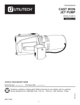 Utilitech 148012 Instrucciones de operación
-
 Utilitech 148013 Guía del usuario
-
red lion RL-SWJ Series El manual del propietario
-
Everbilt EFLS20-HD Manual de usuario
-
-
-
-
Pentair Close Coupled Motor Driven Centrifugal Pump El manual del propietario
-
AquaPRO 70016 Instrucciones de operación


