
Operator's Manual
RN°
4-Cycle Gasoline
LAWN EDGER
Model No. 316.772370
CAUTION: Before using
this product, read this
manual and follow all
safety rules and operating
instructions.
• SAFETY
• ASSEMBLY
• OPERATION
• MAINTENANCE
• PARTS LIST
• ESPANOL, E E1
Sears, Roebuck and Co., Hoffman Estates, IL 60179, U.S.A.
Visit our website: www.sears.com/craftsman
769-03850A

TABLE OF CONTENTS
Rules for Safe Operation ................................. 2
Warranty Information ................................... 4
Know Your Unit ........................................ 5
Assembly Instructions ................................... 6
Oil and Fuel Information ................................. 7
Starting/Stopping Instructions ............................ 8
Operating Instructions ................................... 9
Maintenance and Repair Instructions ....................... 9
Cleaning and Storage .................................. 12
Troubleshooting Chart ................................. 13
Specifications ........................................ 14
Parts List ........................................... E17
SPARK ARRESTOR NOTE
NOTE: For users on U.S. Forest Land and in the states of
California, Maine, Oregon and Washington. All US. Forest Land
and the state of California (Public Resources Codes 4442 and 4443),
Oregon and Washington require, by law that certain internal
combustion engines operated on forest brush and/or grass-covered
areas be equipped with a spark arrestor, maintained in effective
working order, or the engine be constructed, equipped and
maintained for the prevention of fire. Check with your state or local
authorities for regulations pertaining to these requirements. Failure to
follow these requirements could subject you to liability or a fine. This
unit is factory equipped with a spark arrestor. If it requires
replacement, ask your LOCAL SERVICE DEALER to install the
Accessory Part #753-05297 Spark Arrestor Kit
CALIFORNIA PROPOSITION 65 WARNING
THE ENGINE EXHAUST FROM THIS PRODUCT CONTAINS
CHEMICALS KNOWN TO THE STATE OF CALIFORNIA TO
CAUSE CANCER, BIRTH DEFECTS OR OTHER
REPRODUCTIVE HARM.
The purpose of safety symbols is to attract your attention to possible
dangers. The safety symbols, and their explanations, deserve your
careful attention and understanding. The safety warnings do not by
themselves eliminate any danger. The instructions or warnings they
give are not substitutes for proper accident prevention measures.
SYMBOL MEANING
SAFETY ALERT: Indicates danger, warning or
caution. Attention is required in order to avoid serious
personal injury. May be used in conjunction with other
symbo s or p ctographs.
DANGER; Failure to obey a safety warning will result
in serious injury to yourself or to others. Always follow
the safety precautions to reduce the risk of fire, electric
shock and persona n ury.
WARNING; Failure to obey a safety warning can
result in injury to yourself and others. Always follow the
safety precautions to reduce the risk of fire, electric
shock and persona n ury.
CAUTION; Failure to obey a safety warning may result
in property damage or personal injury to yourself or to
others. Always follow the safety precautions to reduce
the rsk of f re, e ectr c shock and persona n ury.
NOTE: Advises you of information or instructions vital to the
operation or maintenance of the equipment.
Read the Operator's Manual and follow all warnings and safety
instructions. Failure to do so can result in serious injury to the
operator and/or bystanders.
FOR QUESTIONS, CALL 1-800-659-5917
• IMPORTANT SAFETY INSTRUCTIONS •
READ ALL INSTRUCTIONS BEFORE OPERATING
WARNING: When using the unit, you must follow the
safety rules. Please read these instructions before
operating the unit in order to ensure the safety of the
operator and any bystanders. Please keep these
instructions for later use.
• Carefully read and understand the operator's manual of the unit
that powers this attachment.
• Read this operating instruction manual carefully. Be thoroughly
familiar with the controls and the proper use of the equipment.
Know how to stop the unit and disengage the controls quickly.
• Do not operate this unit when tired, ill, or under the influence of
alcohol, drugs, or medication.
• Never allow children to operate the equipment. Never allow adults
unfamiliar with the instructions to use the unit. Never allow adults
to operate the equipment without proper instruction.
• All guards and safety attachments must be installed properly
before operating the unit.
• Inspect the unit before use. Ensure the blade is installed correctly
and secure.
• Clear the area to be edged before each use. Remove all objects
such as rocks, broken glass, nails, wire, or string which can be
thrown or become entangled in the edging attachment.
SPECIAL SAFETY WARNINGS FOR LAWN EDGERS
WARNING: Gasoline is highly flammable, and its
vapors can explode if ignited. Take the following
precautions:
• Store fuel only in containers specifically designed and approved
for the storage of such materials.
• Always stop the engine and allow it to cool before filling the fuel tank.
Never remove the cap of the fuel tank, or add fuel, when the engine
is hot. Never operate the unit without the fuel cap securely in place.
Loosen the fuel tank cap slowly to relieve any pressure in the tank.
• Add fuel in a clean, well-ventilated area outdoors where there are
no sparks or flames. Slowly remove the fuel cap only after
stopping engine. Do not smoke while fueling. Wipe up any spilled
fuel from the unit immediately.
• Avoid creating a source of ignition for spilled fuel. Do not start the
engine until fuel vapors dissipate.
• Move the unit at least 30 feet (9.1 m)from the fueling source and site
before starting the engine. Do not smoke. Keep sparks and open
flames away from the area while adding fuel or operating the unit.
• Never start or run the unit inside a closed room or building.
Breathing exhaust fumes can kill. Operate this unit only in a well
ventilated area outdoors.

WHILEOPERATING
• Keep bystanders, especially children and pets, at least 50 ft (15 m)away.
• Wear safety glasses or goggles that are marked as meeting ANSI
Z87.1-1989 standards, and ear/hearing protection when operating
this unit. Wear a face or dust mask if the operation is dusty.
• Wear heavy, long pants, boots, gloves and a long sleeve shirt. Do
not wear loose clothing, jewelry, short pants, sandals or go
barefoot. Secure hair above shoulder level.
• Use the unit only in daylight or good artificial light.
• Use the right tool. Only use this tool for the purpose intended.
• Do not force unit. It will do the job better and with less likelihood
of injury at a rate for which it was designed.
• Use extreme caution when reversing or pulling the unit towards you.
• Do not overreach, take extra care when working on steep slopes
or inclines. Always keep proper footing and balance.
• Always hold the unit with both hands when operating. Keep a firm
grip on the handle.
• Keep hands, face, and feet at a distance from all moving parts. Do
not touch or try to stop the blade when it is rotating. Do not operate
without guards in place.
• Do not operate the engine faster than the speed needed to do the
job. Do not run the engine at high speed when not in use.
• Always stop the engine/motor when operation is delayed or when
walking from one location to another.
• Stop the engine/motor for maintenance, repair, to install or
remove the blade. The unit must be stopped and the blade no
longer turning to avoid injury.
• The blade may become very sharp from use. Always wear heavy
gloves when handling, removing, installing or cleaning the blade.
• If you strike or become entangled with a foreign object, stop the
engine/motor immediately and check for damage. Have any
damage repaired before attempting further operations. Do not
operate unit with a bent, cracked or dull blade. Discard blades
that are bent, warped, cracked or broken.
• Stop the unit IMMEDIATELY if you feel excessive vibration. Vibration
is a sign of trouble. Inspect thoroughly for loose nuts, bolts or damage
before continuing. Repair or replace affected parts as necessary.
• Stop and switch the unit to off for maintenance or repair.
• Keep unit clean of vegetation and other materials. They may
become lodged between the blade and guard.
• A coasting blade can cause injury while it continues to spin after
the unit is stopped. Maintain proper control of the unit until the
blade has completely stopped rotating.
• Use only genuine factory replacement parts and accessories for
this unit. These are available from your authorized service dealer.
Use of any unauthorized parts or accessories could lead to serious
injury to the user or damage to the unit, and void your warranty.
MAINTENANCE AND STORAGE
• Allow the unit to cool before storing or transporting. Be sure to
secure the unit while transporting.
• Store the unit in a locked up and dry or high and dry place to prevent
unauthorized use or damage, out of the reach of children.
• Clean the blade with a hose and water. Wipe the blade with light
machine oil to prevent rust.
• Never douse or squirt the unit with water or any other liquid. Keep
handles dry, clean and free from debris. Clean after each use.
• Keepthese instructions. Referto them often and usethem to instruct other
users. Ifyou loan someone this unit, alsoloan them these instructions.
• Only qualified personnel should perform any repairs or maintenance
procedures that are not described in this manual.
• Check shear bolts, engine mounting bolts and other bolts at frequent
intervals for proper tightness to be sure the equipment is in safe
working condition.
• Inside a building store the machine away from ignition sources.
Allow the engine to cool before storing in any enclosure.
• Always refer to the Operator's Manual instructions for important
details if the lawn edger is to be stored for an extended period.
• Do not attempt to repair the machine unless you have the proper
tools, and instructions for disassembly and repair of the machine.
SAVE THESE INSTRUCTIONS

• SAFETY AND INTERNATIONAL SYMBOLS •
This operator's manual describes safety and international symbols and pictographs that may appear on this product. Read the operator's
manual for complete safety, assembly, operating and maintenance and repair information.
SYMBOL MEANING SYMBOL MEANING
• SAFETY ALERT SYMBOL
Indicates danger, warning or caution. May be used in
conjunction with other symbols or pictographs.
• READ OPERATOR'S MANUAL
[_ ARNING: Read the operator's manual(s) and
follow all warnings and safety instructions. Failure to
do so can result in serious injury to the operator
and/or bystanders.
WEAR EYE AND HEARING PROTECTION
WARNING: Thrown objects and loud noBe can
cause severe eye injury and hearing loss. Wear eye
protection meeting ANSI Z87.1-1989 standards and
ear protection when operating this unit. Use a full
face shield when needed
I _ • UNLEADED FUEL
A ways use c ean. fresh unleaded fuel
_o OIL
Refer to operator s manual for the proper type of oil.
j_ • KEEP BYSTANDERS AWAY
_%,_,'_. WARNING: Keep all bystanders, especially
Jb_p-_l__ children and pets, at least 50 feet (15 m) from the
operating area.
• ON!OFF STOP CONTRO L
QN/START/RUN
jI" HOT SURFACE
I WARNING: Do not touch a hot muffler, gear
,_//})_t,_..v..,housing or cylinder. You may get burned. These parts
get extremely hot from operation. They [emai n hot for
I a sh°rt time after the unit is turned °ff" I
_Tl_.d_ • THROWN OBJECTS AND ROTATING CUTTER I
/. _/_j_. CAN CAUSE SEVERE INJURY
><7 WARNING: Do not operate without the Cutting I
_J'_ attachment shield in place. Keep away from the
rotating cutting attachment.
€_ _ •GARDEN EDGERS - ROTATING BLADE CAN
_ CAUSE SEVERE INJURY I
•;.._ WARNING: Stop the engine and allowthe blade
to stop before removing the blade, or before Cleaning
or performing any maintenance. Keep hands and feet
away from rotat ng bade.
CRAFTSMAN FULL WARRANTY
If this Craftsman product fails due to a defect in material or workmanship within two years from the date of purchase, return it to any Sears store,
Parts and Repair Service Center, or other Craftsman outlet in the United States for free repair (or replacement if repair proves impossible).
This warranty applies for only 90 days if this product is ever used for commercial or rental purposes.
This warranty covers ONLY defects in materal and workmanship. Sears will NOT pay for:
• Expendable items that can wear out from normal use within the warranty period, such as cutting line, filters or spark plugs.
• Repairs necessary because of accident or failure to operate or maintain the product according to all supplied instructions.
• Preventive maintenance, or repairs necessary due to improper fuel mixture, contaminated or stale fuel.
This warranty gives you specific legal rights, and you may also have other rights which vary from state to state.
Sears, Roebuck and Co., Hoffman Estates, IL 60179
Repair Protection Agreements
Congratulations on making asmart purchase. Your new Craftsman® product is designed and manufactured for years of dependable operation. But
like all products, it may require repair from time to time. That's when having a Repair Protection Agreement can save you money and aggravation.
Here's what the Repair Protection Agreement* includes:
[] Expert service by our 10,000 professional repair specialists
[] Unlimited service and no charge for parts and labor on all covered repairs
[] Product replacement up to $1500 if your covered product can't be fixed
[] Discount of 10% from regular price of service and related installed parts not covered by the agreement; also, 10% off regular price of
preventive maintenance check
[] Fast help by phone - we call it Rapid Resolution - phone support from a Sears representative. Think of us as a "talking owner's manual."
Once you purchase the Repair Protection Agreement, a simple phone call is all that it takes for you to schedule service. You can call anytime
day or night, or schedule a service appointment online.
The Repair Protection Agreement is a risk-free purchase. If you cancel for any reason during the product warranty period, we will provide a
full refund. Or, a prorated refund any time after the product warranty period expires. Purchase your Repair Protection Agreement today!
Some limitations and exclusions apply. For prices and additional information in the U.S.A. call 1-800-827-6655.
*Coverage in Canada varies on some items. For full details call Sears Canada at 1-800-361-6665.
Sears Installation Service
For Sears professional installation of home appliances, garage door openers, water heaters, and other major home items, in the U.S.A. or
Canada call 1-800-4-MY-HOME ®.

APPLICATIONS
• Edgingalongpaths,driveways,rockeries,etc.
Muffler
Handle
Throttle
Bail Lock
Lever
Bail Lock
Bail
Oil Plug
Gas Tank
Starter Rope Grip
Straight Metal Shaft
Spark Plug
Zip Ties
Air Filter Cover
Wheel
Depth Adjustment Lever
Wheel
Edger Blade
Blade Shield

HANDLEASSEMBLY
1. Remove the nuts and bolts from the middle handle only, but not
the eyehook.
NOTE: DO NOT remove the bolt and nut in the upper handle.
2. Place the end of the middle handle over the lower handle and
align the holes (Fig. 1). Making sure the "TO START' label is
facing up.
Middle
Handle
Lower
Handle
G .....
Lock-Nuts
G ....
Fig. 1
Bolts
3. Insert two of the bolts previously removed instep 1into these holes
and thread the lock-nuts onto them until hand tight.
4. Using a 3/8" wrench to hold the bolts, tighten the lock-nuts with a
7/16" wrench until firm. DO NOT OVERTIGHTEN.
5. Place the end of the upper handle onto the end of the middle
handle making sure to align the holes. (Fig. 2)
.....
Lock-Nuts
.....
==:=:=_
ol
o
Bolts
@.... @
o
Post
Switch/
Throttle
Assembly
Fig. 3
Uppe_ _dle
÷
©
Upper
Handle
ol
_0 Middle
Handle
Fig. 2
6. Insert two of the bolts previously
removed in step 1 into these
holes and thread the lock-nuts
onto them until hand tight.
7. Repeat step 4 for tightening
of this bolt.
8. Extend the switch/throttle
assembly and wires toward
the top of the handle.
9. Align the switch/throttle
control assembly post with
the hole that can be found on
the side of the upper handle,
(Fig. 3).
10. Firmly push the switch/throttle assembly onto the upper
handle, making sure that the post slightly protrudes through the
hole on the opposite side.
11. Remove the nut and bolt from the throttle control (Fig. 4).
Bolt
Throttle
Fig. 4
12. Align the throttle control with the hole on the right side of the
handle.
13. Insert the bolt thru the hole and thread the lock-nut onto it until
handtight. (Fig. 4).
14. Using a 3/8" wrench to hold the bolt, tighten the lock-nut with a
7/16" wrench until firm. DO NOT OVERTIGHTEN.
15. Cut the Zip tie holding the bail to the handle (Fig. 5).
Z-Hook
4---
Bail
Fig. 5
16. Insert the Z-Hook into the hole on the right side of the bail to
secure the clutch cable to the bail (Fig. 5).
NOTE: Make sure that the bail wire is on top of the upper handle
and not installed under it.
17. Pull out the starter rope and run it thru the eye hook (Fig. 6).
Starter Rope Handle
Eye Hook
Starter
Rope
/
Lock-Nut _
Fig. 6
WARNING" DO NOT run any control wires though the
eye hook. As this may prevent certain safety features from
work ng proper y.
18. Tighten the nut onto the eye hook using a 7/16" wrench to
tighten. DO NOT OVERTIGHTEN.
19. Using the zip ties found in the hardware bag, secure the handle
cables to the lower and middle handle between the eye hook
and the motor housing (see page 5).

J_ JWARNING: OVERFILLING OIL CRANKCASE MAY
CAUSE SERIOUS PERSONAL INJURY. Check and maintain
the proper oil level in the crank case; it is important and
cannot be overemphasized, Check the oil before each use
and change it as needed. See Changing the Oil.
RECOMMENDED OIL TYPE
Using the proper type and weight of oil in the crankcase is extremely
important. Check the oil before each use and change the oil regularly.
Failure to use the correct oil, or using dirty oil, can cause premature
engine wear and failure. Use a high-quality SAE 30 weight oil of API
(American Petroleum Institute) service class SF, SG, SH.
ADDING OIL TO CRANKCASE: INITIAL USE
NOTE: This unit is shipped without oil. In order to avoid damage to the
unit, put oil in the crankcase before you attempt to start the unit,
Your unit is supplied with one 3.04 fluid oz. (90 ml.) bottle of SAE 30
SF, SG, SH oil (Fig. 7).
NOTE: Save the empty oil
bottle. It can be used to
measure the correct
amount during future oil
changes. See Changing
the Oil.
1. Unscrew the top of the
bottle of oil and remove the
paper seal covering the
opening. Replace the top.
Next, cut the tip off the
funnel spout (Fig. 7).
2. Tip unit so that the back of
the engine is facing up in a
vertical position.
3. Removethe oil fill plug
from the crankcase (Fig. 8).
Funnel
Spout
Fig. 7
4-Cycle Motor Oil
Oil Fill Plug
O-Ring
Definition of Blended Fuels
Today's fuels are often a blend of gasoline and oxygenates such as
ethanol, methanol or MTBE (ether). Alcohol-blended fuel absorbs water.
As little as 1% water in the fuel can form acids when stored. Use fresh
fuel (less than 60 days old), when using alcohol-blended fuel.
Using Blended Fuels
Ifyou choose to use a blended fuel, or its use is unavoidable, follow
recommended precautions:
• Always use fresh unleaded gasoline
• Use a gas stabilizer fuel additive
• Drain tank and run the engine dry before storing unit
Using Fuel Additives
The use of a gas stabilizer will inhibit corrosion and minimize the
formation of gum deposits. Using a fuel additive can keep fuel from
forming harmful deposits in the carburetor for up to six (6) months.
Add 0.8 oz. (23 ml.) of fuel additive per gallon of fuel according to
the instructions on the fuel additive container. NEVER add fuel
additives directly to the unit's gas tank.
FUELING THE UNIT
WARNING: Add gasoline in a clean, well ventilated
outdoor area. Wipe up any spilled fuel immediately. Avoid
creating a source of ignition for spilt gasoline. Do not start
the engtne until gasohne vapors dissipate.
_IL WARNING: Gasoline is extremely flammable. Ignited
vapors may explode. Always stop the engine and allow it
to cool before filling the fuel tank. Do not smoke while
filling the tank. Keep sparks and open flames at a distance
from the area.
1. Remove the gas cap.
,_ WARNING: Remove gas cap slowly to avoid in ury
from fuel spray. Never operate the unit without the gas
cap secure y n p ace.
2. Place the gas container's spout into the fill hole on the fuel tank
(Fig. 10) and fill the tank.
Gas Can Spout
Oil Fill Hole-_
Fig. 8
4. Pour the entire bottle of oil
into the oil fill hole (Fig. 9).
NOTE: Never add oil to the
gas or gas tank.
5. Wipe up any oil that may
have spilled
oil fill plug.
Check oil before each use and
change as needed. Refer to
Checking the Oil Level.
RECOMMENDED FUEL TYPE
Old gasoline is the primary
reason for improper unit
performance. Be sure to use
fresh, clean, unleaded gasoline. Fig. 9
Dispose of the old gasoline in accordance to Federal, State and
Local regulations
NOTE: This is a four cycle engine. Inorder to avoid damage to the unit,
do not mix oil with the gasoline.
Gas Cap
Gas Tank
Fig. 10
NOTE: Fill or add gas to the tank only when the edger is in the
horizontal position.
NOTE: Do not overfill the tank.
3. Wipe up any gasoline that may have spilled.
4. Reinstall the gas cap.
5. Move the unit at least 30 ft. (9.1 m) from the fueling source and
site before starting the engine.

A WARNING: Operate this unit only in a well- ventilated
outdoor area. Carbon monoxide exhaust fumes can be
etha n a conf ned area.
_, WARNING: Avoid accidental starting. Make sure you
are in the starting position when pulling the starter rope
(Fig. 14). To avoid serious injury, the operator and unit
must be in a stable position while starting.
STARTING INSTRUCTIONS
1. Check the oil level in the crankcase. Refer to Checking
the Oil Level.
2. Fill the fuel tank with fresh, clean unleaded gasoline. Refer
to Fueling the Unit.
NOTE: There is no need to turn the unit on. The On/Off Stop
Control is in the ON ( I ) position at all times (Fig. 11).
........ 3. Fully press and release the primer bulb 10 times, slowly.
Some amount of fuel should be visible in the primer bulb
and fuel lines (Fig. 12). If you can't see fuel in the bulb,
press and release the bulb as many times as it takes
before you can see fuel in it.
IF UNIT IS BELOW 40°F... move the Cold Weather Start Lever
to the closed position (Fig. 13) and continue to step 4. DO
NOT move this lever to the closed position if the unit's
temperature is above 40°F.
4. Stand in the starting position (Fig. 14) and make sure the
throttle control (Fig. 15) is in the SLOW (_) position.
5. Pull the starter rope out a short distance until you feel
some resistance (this is usually around 2-4 inches). Then
pull the starter rope out with a controlled and steady
motion. Repeat this 5 times. The engine should start.
NOTE: Do not engage the bail while pulling the starter rope
(Fig. 14) or the unit will not start.
6. If the engine starts, allow the engine to warm up for 15 to
30 seconds then move the throttle control to the FAST (_)
position.
IF ENGINE STARTS AND WEATHER IS COLD... (below
40°F), move the Cold Weather Start Lever to the open
position (Fig. 13) and let the engine warm up for 30 to 60
seconds.
..............IF... the engine does NOT start, go back to step 3.
IF... the engine stops while the throttle control is in the FAST
(_,) position, go back to step 4.
WARM UNIT RESTART... Once the engine is warm, move
throttle control lever to the SLOW (_) position and pull
the starter rope to restart. Do not squeeze the bail while
pulling the starter rope.
NOTE: The unit uses the Incredi-PulF Mstarting system with
MAX FIRE IGNITION TM , which significantly reduces
the effort required to start the engine. You must pull
the starter rope out far enough to hear the engine
attempt to start. There is no need to pull the rope
briskly-- there is no harsh resistance when pulling. Be
aware that this starting method is vastly different from
(and much easier than) what you may be used to.
STOPPING INSTRUCTIONS
1. Release your hand from the bail and move throttle control lever
to the SLOW (-,_) position. Allow the engine to cool down by
idling.
WARNING: Do not force the throttle control handle
back past the Turtle on the throttle label. This could
damage the un t.
2. Press and hold On/Off Stop Control in the OFF (0) position until
engine comes to a complete stop (Fig. 11).
Switch
Fig. 11
r
Fig. 12
\
Primer
Bulb
II Cold Weather IZ_3
H Start Lever [Z_3
Open Closed
Fig. 13
Bail
Fig. 14
Throttle
Label
Fast
Slow
Throttle Control
Fig. 15

HOLDINGTHEUNIT
eye, hearing, foot and body
protection to reduce the risk of
injury when operating this unit.
Before operating the unit, stand in the
operating position (Fig. 16). Check for the
following:
• The operator is wearing eye protection
and proper clothing.
• Both hands are holding the handle bar
firmly.
• The edger wheel adjusted for proper
cut depth as shown in Figure 17 and
edger positioned as shown in Fig. 16.
ADJUSTING EDGER CUTTING DEPTH
1. Grasp the depth adjustment lever
located beside the front wheel (Fig. 17).
2. To raise the cutting blade, move the
lever toward the front of the wheel
bracket (Fig. 17).
3. To lower the cutting blade, move the
lever toward the rear of the wheel
bracket.
OPERATING THE UNIT
Once the unit has started:
1. Tilt the unit back until
the blade is not in
contact with the
ground.
2. Lift the bail (Fig. 16) -_--?_....
and, hold it against the _, Whee
unit s handle to /// Bracket
engage the blade and _L__.. \
keep it rotating. _
3. Slowly lower the unit -_ \ d__\ ///
until the front wheel is "--..,._/_,_///
in contact with the _ _}_t\
ground.
Fig. 16
Fig. 17
Lift
Bail
Thumb
Wheel
Depth
Adjustment
Lever
NOTE: Make sure you have a firm grip on the unit. The spinning
blade will contact the ground before the wheel does and
will create continuous forward thrust.
4. Walk slowly behind the unit while maintaining a firm grip on the unit.
TIPS FOR BEST EDGING RESULTS
• Do not force the edger. Edge the first time at a lesser depth,(No
more than 1/2" depth cut per pass), then do the area again with a
deeper setting.
• Walk the edger at a slow, even pace.
• Check the blade condition. As it wears it becomes smaller, thus
reducing the cutting depth performance. Replace with a new blade
when the blade has worn to the blade's wear limit holes (Fig. 18).
Blade
Wear Limit
Holes
Fig. 18
ADJUST BELT TENSION
If blade fails to turn when the bail is pulled, then:
1. Locate small thumb wheel on top of the belt housing (Fig. 17).
2. Turn the wheel clockwise 1 revolution to increase the tension
on the belt.
3. Try pulling the bail and see if the blade turns. If not, repeat step
2 until the blade turns.
• MAINTENANCE SCHEDULE °
I_11_ I WARNING: To prevent serious injury, never perform
I
maintenance or repairs with unit running, Always service
and repair a cool unit. Disconnect the spark plug wire to
ensure that the unit cannot start.
Perform these required maintenance procedures at the frequency
stated in the table. These procedures should also be a part of any
seasonal tune-up.
NOTE: Some maintenance procedures may require special tools or
skills. If you are unsure about these procedures take your
unit to a Sears or other qualified service dealer.
NOTE: Maintenance, replacement, or repair of the emission control
devices and system may be performed by a Sears or other
qualified service dealer.
In order to assure peak performance of your engine, inspection of
the engine exhaust port may be necessary after 50 hours of
operation. If you notice lost RPM, poor performance or general lack
of acceleration, this service may be required. If you feel your engine
is in need of this inspection, refer service to a Sears or other
qualified service dealer for repair. DO NOT attempt to perform this
process yourself as engine damage may result from contaminants
involved in the cleaning process for the port.
FREQUENCY MAINTENANCE REQUIRED SEE
Before using Fill fuel tank with fresh fuel p. 7
Check Oil p .10
Every 10 hrs Clean and re-oil air filter p. 10
After 1st 10 hrs Change Oil p. 10
After 25 hrs & Every 25 hrs Change Oil p. 10
Every 50 hrs Clean Spark Arrestor p. 12
Every 10 hrs Check rocker arm to valve clearance and adjust p. 11
Every 25 hrs Check rocker arm to valve clearance and adjust p. 11
Every 25 hrs Check spark plug condition and gap p. 12
9

BLADE REPLACEMENT
WARNING: To avoid serious personal in u[y, always
I
wear g oves wh e hand ng, remov ng or nsta tng the bade. I
1. Place a 5/16" Allen Spindle Hole
wrench in the spindle
hole (Fig. 19).
2. While holding the Allen
wrench in place, loosen
the nut with a 15/16"
wrench by turning it
counterclockwise (Fig.
3. Remove the nut and
blade. Keep the nut for
new blade installation.
4. Install the new blade and
nut (Fig. 20).
5. While holding the Allen Loosen
wrench in the spindle hole,
tighten the nut by turning
the wrench clockwise until
tight (Fig. 21). Fig. 19
Edger Blade _ Nut Tighten
Fig. 20 Fig. 21
NOTE: Make sure that the blade stays flat and centered against
the output shaft throughout installation.
WARNING: Verify the blade is flat against the output
shaft after the nut is tightened. Ifthe blade is off-center,
the unit will be damaged by vibration, and the blade may
f y off, wh ch can cause serous persona n ury.
REPLACEMENT PARTS
Blade ........................................ 753-05562
Nut ......................................... 753-05549
Use only Craftsman replacement parts.
CHECKING THE OIL LEVEL
The importance of checking and maintaining the proper oil level inthe
crankcase cannot be overemphasized. Check oil before each use:
1. Stop the engine and allow oil to drain into the crankcase.
2. Place the unit on a level surface to get an accurate oil level
reading (Fig. 22).
Max Oil Fill Line
Fig. 22
3. Keep dirt, grass clippings and other debris out of the engine. Clean
the area around the oil fill plug before removing it.
4. Remove the oil fill plug.
5.
6.
Look into the oil fill hole, use a flashlight if needed. The oil should
be just touching the innermost thread (Fig. 22).
If the oil level is not touching the innermost thread on the oil fill
hole, add a small amount of oil to the oil fill hole and recheck
(Fig. 23). Repeat this procedure until the oil level reaches the
innermost thread on the oil fill hole.
Fig. 23
NOTE: Do not overfill the unit.
NOTE: Make sure the O-ring is in place on the oil fill plug when
checking and changing the oil (Fig. 8).
CHANGING THE OIL
CAUTION: Wear gloves to prevent injury when handling I
the un t. I
For a new engine, change the oil after the first 10 hours of operation.
Change the oil while the engine is still warm. The oil will flow freely
and carry away more impurities.
1. Unplug spark plug boot to
prevent accidental starting.
2. Remove the oil fill plug.
3. Pour the oil out of the oil fill
hole and into a container by
tipping the unit to a vertical
position (Fig. 24). Allow ample
time for complete drainage.
4. Wipe up any oil residue on the
unit and clean up any oil that
may have spilled. Dispose of
the oil according to Federal,
State and local regulations.
5. Refill the crankcase with 3.04
fluid ounce (90 ml or 3/8 cup) Fig. 24
of SAE 30 SF, SG, SH oil.
NOTE: Use the bottle and spout saved from initial use to measure the
correct amount of oil. The top of the label on the bottle measures
approximately 3.04 ounces (90 ml or 3/8 cup) (Fig. 23).Check the
level; See Checking the Oil Level. Ifthe levelis low, add a small
amount of oil and recheck. Do not overfill (Fig. 23).
6. Replace the oil fill plug.
7. Reconnect the spark plug boot.
AIR FILTER MAINTENANCE
Cleaning the Air Filter
_, WARNING: To avoid serious personal injury, always
turn the unit off and allow it to cool before you clean or
service it.
Clean and re-oil the airfilter every 10 hours of operation. It is an important
item to maintain. Failureto maintain your airfilter properly can result in
poor performance or can cause permanent damage to your engine.
1. Open the air filter cover. Push the tab on the left side of the cover
in, then swing the air filter cover out and off of the air filter housing
(Fig. 25).
2. Remove the air filter and the screen that sits behind it (Fig. 25).
3. Wash the filter in detergent and water (Fig. 26). Rinse the filter
thoroughly and allow it to dry.
4. Apply enough clean SAE 30 motor oil to lightly coat the filter (Fig. 27).
5. Squeeze the filter to spread and remove excess oil (Fig. 28).
6. Replace the filter (Fig. 25).
10

NOTE:Iftheunitisoperatedwithouttheairfilter,youwillVOIDthe
warranty.
7. Reinstalltheairfiltercover.Positionthetabsonthesidesofthe
airfiltercoverontotheslotsatthetopofthebackplate(Fig.25).
8. Pushthecoverinuntilthetabontheairfilterbackplatesnaps
intoplaceintheslotontheairfiltercover(Fig.25).
Screen
Air Filter
i
Tab
Air Filter Housing
Hooks /
Air Filter Cover
Air Filter Slot
Fig. 25
Fig. 26
IDLE SPEED ADJUSTMENT
Fig. 27
_k WARNING: To
prevent serious
personal injury, make
sure the blade has
stepped rotating
before you turn it off.
The idle speed of the engine is
adjustable. An idle adjustment
screw is between the air filter
cover and the engine starter
housing (Fig, 29).
NOTE: Careless adjustments can Fig. 28
seriously damage your
unit. Aside from the idle speed, only a Sears or other
qualified service dealer should make carburetor adjustments.
1. Check Fuel
Old fuel is usually the reason for improper unit performance. Drain
and refill the tank with fresh fuel prior to making any adjustments.
Refer to Oil and Fuel Information.
2. Clean Air Filter
The condition of the air filter is important to the operation of the unit.
A dirty air filter will restrict air flow. This is often mistaken for an out
of adjustment idle. Check the
condition of the air filter before
adjusting the idle speed screw.
Refer to Air Filter Maintenance.
3. Adjust Idle Speed Screw
If, after checking the fuel and
cleaning the air filter, the engine
still will not idle, adjust the idle
speed screw as follows:
1. Start the engine and let it
run at a high idle for a
minute to warm up. Refer
to Starting/Stopping
Instructions.
2. Move the throttle control
Idle
ustment
Screw
Fig. 29
lever to the Slow position (.4_) and let the engine idle. If the
engine stops, insert a small phillips in between the Air Filter
Cover and the Engine Cover (Fig. 29).
NOTE: Do not engage the Blade Clutch Lever while adjusting the
idle speed screw to ensure that the blade will not rotate.
3. Turn the idle speed screw in, clockwise, 1/8 of a turn at a time
(as needed) until the engine idles smoothly.
Checking the fuel, cleaning the airfilter, and adjusting the idle speed
should solve most engine problems. If not and all of the following aretrue:
• the engine will not idle
• the engine hesitates or stalls on acceleration
• there is a loss of engine power
Have the carburetor adjusted by an authorized service dealer.
ROCKER ARM CLEARANCE
This requires disassembly of the engine. Ifyou feel unsure or unqualified to
perform this, take the unit to an authorized service center.
NOTE: Inspect the valve to rocker arm clearance with a feeler
gauge after the first 10 hours of operation and every 25
hours of operation.
• The engine must be cold when checking or adjusting the valve
clearance.
• This task should be performed inside, in a clean, dust free area.
1. Remove the six (6) screws on the back of the engine cover with a
Flat-head or T-25 Torx screwdriver (Fig. 30).
Fig. 30
Rocker Arm
Cover
Remove
Screws
Fig. 31
2. Disconnect the spark Remove
plug wire. Screws
3. Clean dirt from around
the spark plug. Remove
the spark plug from the
cylinder head by
tuming a 5/8 in. socket
counterclockwise.
4. Remove the engine
cover (Fig. 30).
5. Clean dirt from around
the rocker arm cover.
Remove the screw
holding the rocker arm
cover with a large flat
blade screwdriver or
Torx T-25 bit (Fig. 31).
Remove the rocker
arm cover and gasket.
6. Pull the starter rope
slowly to bring the piston to the
top of its travel, (known as top
dead center). Check that:
• The piston is at the top of its travel.
Look in the spark plug hole to view
the piston (Fig. 32)
• Both rocker arms move freely, and
both valves are closed
Ifthese statements are not true, repeat
step 6.
7. Slide the feeler gauge between the
rocker arm and the top of each
valve stem. Measure the clearance
Spark
Plug
Hole
\
11

Rocker Arms INTAKE Adjusting
\ 1 Screws
Feeler Gauge
@
SparkPlugNoIe J @
Fig. 32
between the valve stem and rocker arm (Fig. 32). Measure both
the intake and exhaust valves.
The recommended clearance for both intake and exhaust is
.003-.006 in. (.076 -0.152 mm). Use a standard automotive .005 in.
(0.127 mm) feeler gauge. The feeler gauge should slide between the
rocker arm and valve stem with a slight amount of resistance,
without binding. See Figures 32 and 33.
Adjusting
.003-.006 in.
(.076-.152 mm)
Rocker Arm
/
Feeler Gauge
Intake
Valve Stem
Exhaust
Valve Stem
Fig. 33
8. If the clearance is not within specification:
a. Turn the adjusting nut using a 5/16 inch (8 mm) wrench or nut
driver (Fig. 32).
• To increase clearance, turn the adjusting nut counterclockwise.
• To decrease clearance, turn the adjusting nut clockwise.
b. Recheck both clearances, and adjust as necessary.
9. Reinstall the rocker arm cover using a new gasket. Torque the
screw to 20-30 in•lb (2.2-3.4 N•m).
10. Check the spark plug and reinstall. See Replacing the Spark Plug.
11. Replace the spark plug wire.
12. Reinstall the engine cover. Check alignment of the cover before
tightening the screws. Tighten screws.
REPLACING THE SPARK PLUG
Use a replacement part number 753-05255 spark plug. The correct
air gap is 0.025 in. (0.635 mm). Remove the plug after every 25
hours of operation and check its condition.
1. Stop the engine and allow it to cool. Remove the six (6) screws
on the back of the engine cover with a Flat-head or T-25 Torx
screwdriver (Fig. 30).
2. Grasp the plug wire firmly and pull the cap from the spark plug.
3. Clean dirt from around the spark plug. Remove the spark plug from
the cylinder head by turning a5/8 in.socket counterclockwise.
_I_ WARNING: Do not sand blast, scrape or clean
e ectrodes. Grt n the eng ne cou d damage the cylinder.
4. Replace cracked, fouled or dirty spark plug. Set the air gap at
0.025 in. (0.635 mm) using a feeler gauge (Fig. 34).
5. Install a correctly-gapped spark plug
in the cylinder head. Turn the 5/8 in.
socket clockwise until snug.
If using a torque wrench, torque to:
110-120 in.•lb. (12.3-13.5 N•m)
Do not over tighten.
SPARK ARRESTOR MAINTENANCE
1. Remove the rear engine cover. See
Rocker Arm Clearance.
2. With a flat blade screwdriver or Torx
T-20 bit and a T-25 bit, remove the
screws attaching the
spark arrestor cover
to the muffler (Fig. 35).
3. Pull the tab on the
spark arrestor cover
out of the muffler.
Remove the spark
arrestor cover.
4. Remove the spark
arrestor screen from
the spark arrestor
cover.
5. Clean the spark
arrestor screen with a
wire brush or replace it.
6. Reinstall the spark
arrestor screen, spark
arrestor cover and
screws.
CLEANING
Fig. 34
=re=or
o_ Screen
r_ T-25
q.w
SparckArrreStor _I_/ q_
T-30 Screw
Fig. 35
WARNING: To avoid serious personal injury, always turn
your unit off and allow it to cool before you clean or service it.
Use a small brush to clean off the outside of the unit. Do not use
strong detergents. Household cleaners that contain aromatic oils
such as pine and lemon, and solvents such as kerosene, can damage
plastic housing or handle. Wipe off any moisture with a soft cloth.
STORAGE
• Never store the unit with fuel in the tank where fumes may reach
an open flame or spark.
• Allow the engine to cool before storing.
• Lock up the unit to prevent unauthorized use or damage.
• Store the unit in a dry, well-ventilated area.
• Store the unit out of the reach of children.
LONG TERM STORAGE
1. Drain all gasoline from the gas tank into acontainer. Do not use
gas that has been stored for more than 60 days. Dispose of the old
gasoline in accordance to Federal, State, and Local regulations.
2. Start the engine and allow it to run until it stalls. This ensures
that all gasoline has been drained from the carburetor.
3. Allow the engine to cool. Remove the spark plug and put 5
drops of high quality motor oil into the cylinder. Pull the starter
rope slowly to distribute the oil. Reinstall the spark plug.
NOTE: Remove the spark plug and drain all of the oil from the
cylinder before attempting to start the edger after storage.
4. Change the oil, referring to Changing the Oil. Dispose of the old
oil in accordance to Federal, State and Local regulations.
5. Thoroughly clean the unit and inspect for any loose or
damaged parts. Repair or replace damaged parts and tighten
loose screws, nuts or bolts. The unit is ready for storage.
TRANSPORTING
• Allow the engine to cool before transporting.
• Secure the unit while transporting.
• Drain the gas tank before transporting.
• Tighten gas cap before transporting.
12

REPLACING THE DRIVE BELT
To replace the drive belt:
1. Place the unit on a level surface, preferrably a workbench.
2. Move the depth adjustment lever all the way forward (Fig. 36) to
raise the front wheel enough to provide clearance for the blade
to turn freely.
Depth
Adjustment
Lever
3.
Fig. 36
Using a flat-head or T-20 Torx screwdriver, remove the 3 Torx
screws holding the belt cover to the belt housing (Fig. 37).
Blade
Assembly
\
Hex Screw
Fig. 39
Drive Pulley
Belt
Tensioner
Belt
Lip
3 Torx Screws
Edge
4.
5.
Fig. 37
Remove the belt cover.
Using a 3/8-inch wrench, remove the three hex screws holding
the blade assembly to the belt housin( (Fig. 38).
Fig. 38
6. Remove the blade assembly from the belt housing and the belt
from the blade assembly.
7. Using a 3/8-inch wrench, remove the screw holding the belt
guard to the unit chassis (Fig. 39).
8. Remove the belt guard and belt.
9. Insert a new belt into the belt guard (Fig. 40).
10. Place the belt guard and belt over the drive pulley (Fig. 39). Make
sure the bottom of the belt rests on the belt tensioner (Fig. 39).
11. While holding the belt guard and belt in place, hand-start the
screw that holds the belt guard in place.
12. Using a 3/8-inch wrench, tighten the belt guard hex screw.
Fig. 40
13. Torque the hex screw to 80-100 in.lbs.
14. Hold the blade assembly next to the belt housing and place the
belt over the plastic blade pulley (Fig. 41).
Plastic Blade Pulley
Belt
Blade Assembly
Fig. 41
15. Align the grooves and ridges inside the belt with the ridges and
grooves on the pulley.
16. Insert the blade assembly into the belt housing. Make sure that
the bottom of the belt rests on the belt tensioner (Fig. 39).
17. Check to make sure that the belt is still properly aligned with
the plastic blade pulley. If it has moved, realign the belt with the
plastic blade pulley as described in step 15 above.
18. While holding the blade assembly in place, hand-start the hex
screws that hold the blade assembly in place (Fig. 38).
19. Using a 3/8-inch wrench, tighten the hex screws.
20. Torque the hex screws to 85-95 in.lbs.
21. Slide the belt cover behind the blade assembly so that the lip of the
blade cover fits behind the metal edge ofthe blade assembly (Fig.37).
22. While holding the belt cover in place, hand start the screw that
holds it in place.
23. Using a flat-head or T-20 Torx screwdriver, tighten the screws.
24. Torque the screws to 15-20 in.lbs.
13

CAUSE
Empty fuel tank
Old fuel
Plugged spark arrestor
W :1#[€t1#1=UAvlIIIIII #[e]nlIm]I!
CAUSE
Air filter is plugged
Improper idle speed
CAUSE
Old fuel
Improper carburetor adjustment
Plugged spark arrestor
CAUSE
Old fuel
Improper carburetor adjustment
Blade cutting depth too deep
i :| W__Ie] _vlvd II m _[e_ m i |J :| _
CAUSE
Blade bound with grass
ACTION
Fill fuel tank with new fuel
Drain gas tank and add fresh fuel
Clean or replace spark arrestor
ACTION
Replace or clean the air filter
Adjust idle speed
ACTION
Drain gas tank and add fresh fuel
Take to a Sears or other qualified service dealer for adjustment
Clean or replace spark arrestor
ACTION
Drain gas tank and add fresh fuel
Take to a Sears or other qualified service dealer for adjustment
Adjust blade cutting depth
ACTION
Stop the engine and clean the blade
Drive belt broken Replace belt
Iffurther assistance is required, contact Sears or other authorized service dealer.
. LP? 1
fC_'_ll[._r find t:he answer and more on manage_ayhOmeoCem - for free! t
)
Find this and aLLyour other product manuals online.
Get answers from our team of home experts.
°°Get a personalized maintenance plan for your home.
Find information and tools to help with home projects.
÷anage[ ho e
14

m ( lQll
Displacement....................................................................................... 1,8 CU, in. (29 CO)
Operating RPM .......................................................................................... 6,800+ rpm
Idle Speed RPM .................................................................................... 2,800 - 3,600 rpm
Ignition Type .............................................................................................. Electronic
On/Off Stop Control ....................................................................................... Momentary
Valve clearance ........................................................................ 0.003-0.006 in. (0.076-0.152 ram)
Spark Plug Gap ................................................................................. 0.025 inch (0.635 ram)
Lubrication .............................................................................................. SAE 30 Oil
Crankcase Oil Capacity ........................................................................ 3.04 oz (90 ml or 3/8 cup)
Fuel .................................................................................................... Unleaded
Carburetor .................................................................................... Diaphragm, All-Position
Starter ..................................................................................... Incredi-Pull TM Auto Rewind
Muffler ........................................................................................... Baffled with Guard
Throttle .............................................................................................. Variable Speed
Fuel Tank Capacity ..................................................................................... 14 oz (414 ml)
mmml(lln
Unit Weight ...................................................................................... 22.1 Ibs. (10,02 kg.)
Cutting Depth (maximum) ............................................................................. 1.75 in. (44.5 mm)
All specifications are based on the latest product information available at the time of printing. We reserve the right to make changes at
any time without notice.
California / EPA Emission Control Warranty Statement
Your Warranty Rights and Obligations
The California Air Resources Board, the Environmental Protection Agency, and Sears Brands LLC (Sears) are pleased to explain the emission
control system warranty on your 2007 and later small off-road engine. InCalifornia and the 49 states, new small off-road engines must be designed,
built and equipped to meet the state's stringent anti-smog standards. Sears must warrant the emission control system on your small off-road engine
for the periods of time listed below provided there has been no abuse, neglect or improper maintenance of your small off-road engine.
Your emission control system may include parts such as the carburetor or fuel-injection system, the ignition system, and catalytic converter.
Also included may be hoses, belts, connectors and other emission-related assemblies.
Where a warrantable condition exists, Sears will repair your small off-road engine at no cost to you including diagnosis, parts and labor.
The 2007 and later small off-road engines are warranted for two years. If any emission-related part on your engine is defective, the part will be
repaired or replaced by Sears.
Owners Warranty Responsibilities
As the small off-road engine owner, you are responsible for the performance of the required maintenance listed in your operator's manual.
Sears recommends that you retain all receipts covering maintenance on your small off-road engine, but Sears cannot deny warranty solely
for the lack of receipts or for your failure to ensure the performance of all scheduled maintenance.
• As the small off-road engine owner, you should however be aware that Sears may deny you warranty coverage if your small off-road
engine or a part has failed due to abuse, neglect, improper maintenance or unapproved modifications.
• You are responsible for presenting your small off-road engine to a Sears Authorized Service Center as soon as a problem exists. The
warranty repairs should be completed in a reasonable amount of time, not to exceed 30 days.
If you have any questions regarding your warranty rights and responsibilities, you should call 1-800-659-5917.
Manufacturer's Warranty Coverage
• The warranty period begins on the date the engine or equipment is delivered to the retail purchaser.
• The manufacturer warrants to the initial owner and each subsequent purchaser, that the engine is free from defects in material and
workmanship which cause the failure of a warranted part for a period of two years.
• Repair or replacement of warranted part will be performed at no charge to the owner at an Authorized Sears Service Center. For the
nearest location please contact Sears at: 1-800-659-5917.
• Any warranted part which is not scheduled for replacement, as required maintenance or which is scheduled for only for regular inspection
to the effect of "Repair or Replace as Necessary" is warranted for the warranty period. Any warranted part which is scheduled for
replacement as required maintenance will be warranted for the period of time up to the first scheduled replacement point for that part.
• The owner will not be charged for diagnostic labor which leads to the determination that a warranted part is defective, if the diagnostic
work is performed at an Authorized Sears Service Center.
• The manufacturer is liable for damages to other engine components caused by the failure of a warranted part still under warranty.
• Failures caused by abuse, neglect or improper maintenance are not covered under warranty.
• The use of add-on or modified parts can be grounds for disallowing a warranty claim. The manufacturer is not liable to cover failures of
warranted parts caused by the use of add-on or modified parts.
15

• In order to file a claim, go to your nearest Authorized Sears Service Center. Warranty services or repairs will be provided at all Authorized
Sears Service Centers.
• Any manufacturer approved replacement part may be used in the performance of any warranty maintenance or repair of emission related
parts and will be provided without charge to the owner. Any replacement part that is equivalent in performance or durability may be used
in non-warranty maintenance or repair and will not reduce the warranty obligations of the manufacturer.
Emission Warranty Parts List:
The following components are included in the emission-related warranty of the engine: air filter, carburetor, primer, fuel lines, fuel pick up/fuel
filter, ignition module, spark plug, and muffler. Valves and Cam are additionally included if your engine is a 4-Stroke Model.
California Evaporative Emission Control Warranty Statement
Your Warranty Rights and Obligations
The California Air Resources Board and Sears Brands LLC (Sears) is pleased to explain the evaporative emission control system's warranty
on your 2007 model year and later small off-road (equipment type) engine. In California, new equipment that use small off-engines must be
designed, built, and equipped to meet the State's stringent anti-smog standards Sears must warrant the evaporative emission control
system on your small off-road Lawn & Garden engine for the period listed below provided there has been no abuse, neglect or improper
maintenance of your equipment.
Your evaporative emission control system may include parts such as: carburetors, fuel tanks, fuel lines, fuel caps, valves, canisters, filters,
vapor hoses, clamps, connectors, and other associated components. For engines less than or equal to 80 cc, only the fuel tank is subject to
the evaporative emission control warranty requirements of this section. The displacement of your small off road engine is less than 80 cc.
Manufacturer's Warranty Coverage
This evaporative emission control system is warranted for two years. If any evaporative emission-related part on your equipment is defective,
the part will be repaired or replaced by Sears.
Owner's Warranty Responsibilities
• As the small off-road Lawn & Garden engine owner, you are responsible for performance of the required maintenance listed in your owner's
manual. Sears recommends that you retain all receipts covering maintenance on your Lawn & Garden Engine but Sears cannot deny warranty
solely for the lack of receipts.
• As the small off-road Lawn & Garden engine owner, you should however be aware that the Sears may deny you warranty coverage if your
fuel tank has failed due to abuse, neglect, or improper maintenance or unapproved modifications.
• You are responsible for presenting your Lawn & Garden fuel tank to Sears distribution center or service center as soon as the problem
exists. The warranty repairs should be completed in a reasonable amount of time, not to exceed 30 days. If you have a question
regarding your warranty coverage, you should contact Sears at 1-800-659-5917.
Defects Warranty Requirements
(a) The warranty period begins on the date the engine or equipment is delivered to an ultimate purchaser.
(b) General Evaporative Emissions Warranty Coverage. The fuel tank must be warranted to the ultimate purchaser and any subsequent
owner that the evaporative emission control system when installed was:
(1) Designed, built, and equipped so as to conform with all applicable regulations; and
(2) Free from defects in materials and workmanship that causes the failure of a warranted part for a period of two years.
(c) The warranty on evaporative emissions-related parts will be interpreted as follows:
(1) Any warranted part that is not scheduled for replacement as required maintenance in the written instructions must be warranted for the
warranty period defined in subsection (b)(2). If any such part fails during the period of warranty coverage, it must be repaired or replaced by
Sears. Any such part repaired or replaced under the warranty must be warranted for a time not less than the remaining warranty period.
(2) Any warranted part that is scheduled only for regular inspection in the written instructions must be warranted for the warranty period
defined in subsection (b)(2). A statement in such written instructions to the effect of "repair or replace as necessary" will not reduce the
period of warranty coverage. Any such part repaired or replaced under warranty must be warranted for a time not less than the
remaining warranty period.
(3) Any warranted part that is scheduled for replacement as required maintenance in the written instructions must be warranted for the period of
time prior to the first scheduled replacement point for that part. Ifthe part fails prior to the first scheduled replacement, the part must be
repaired or replaced by the Sears. Any such part repaired or replaced under warranty must be warranted for atime not less than the
remainder of the period prior to the first scheduled replacement point for the part.
(4) Repair or replacement of any warranted part under the warranty provisions of this article must be performed at no charge to the owner
at a warranty station.
(5) Not withstanding the provisions of subsection (4) above, warranty services or repairs must be provided at distribution centers that are
franchised to service the subject engines or equipment.
(6) The owner must not be charged for diagnostic labor that leads to the determination that a warranted part is in fact defective, provided
that such diagnostic work is performed at a warranty station.
(7) Throughout the evaporative emission control system's warranty period set out in subsection (b)(2), Sears must maintain a supply of
warranted parts sufficient to meet the expected demand for such parts.
(8) Manufacturer approved replacement parts must be used in the performance of any warranty maintenance or repairs and must be
provided without charge to the owner. Such use will not reduce the warranty obligations of the manufacturer issuing the warranty.
(9) The use of any add-on or modified parts will be grounds for disallowing a warranty claim made in accordance with this article. The
manufacturer issuing the warranty will not be liable under this Article to warrant failures of warranted parts caused by the use of an add-
on or modified part.
(10) Sears shall provide any documents that describe the warranty procedures or policies within five working days of request by the Air
Resources Board.
Emission Warranty Parts List
(1) Fuel Tank
Written instructions for the maintenance and use of the evaporative emissions control system by the owner shall be furnished with each new
engine or equipment.
16

Manual del Operador
RN°
4-Tiempos a gasolina
RECORTADOR DE BORDES
Model No. 316.772370
PRECAUCION: Antes de
utilizar este producto, lea
este manual y siga todas
las reglas de seguridad y
las instrucciones de
funcionamiento.
• SEGURIDAD
• MONTAJE
• FUNCIONAMIENTO
• MANTENIMIENTO
• LISTADO DE PIEZAS
Sears, Roebuck and Co., Hoffman Estates, IL 60179, U.S.A.
Visite nuestro sitio web" www.sears.com/craftsman
769-03850A

INDICE DE CONTENIDOS
Normas para una operaci6n segura ....................... E2
Garantia ............................................ E4
Conozca su unidad .................................... E5
Instrucciones de ensamble .............................. E6
Informaci6n del aceite y del combustible ................... E7
Instrucciones de arranque y apagado ..................... E8
Instrucciones de operaci6n ............................. E9
Instrucciones de mantenimiento y reparaci6n ............... E9
Limpieza y almacenamiento ............................ E12
Cuadro de soluci6n de problemas ....................... E13
Especificaciones ..................................... E14
Lista de Piezas ...................................... E17
PARACHISPAS
NOTA: Para los usuarios en tierras forestales de los EE.UU. y en los
estados de California, Maine, Oregon yWashington. Todos losterrenos
forestales de los EE.UU. y el estado de California (C6digos de Recursos
PQblicos 4442 y 4443), Oregon y Washington, requieren per decreto, que
ciertos motores de combusti6n interna que se hagan funcionar en zones
boscosas y/o zonas cubiertas per pastizales, esten equipados con un
parachispas, que sean mantenidos en buen estado de funcionamiento o
que el motor sea construido, este equipado y sea mantenido para evitar
incendios. Consulte los reglamentos pertinentes a esos requisitos con las
autoridades estatales o locales. Elincumplimiento de esos requisitos puede
responsabilizarie o sometede a la imposici6n de una multa. Esta unidad
fue equipada en la fabrica con un parachispas. Si requiere sustituci6n,
hay unaPantalla Parachispas disponible, Pieza# 753-05297 al contactar
el departamento de servicio.
PROPOSICION 65 DE CALIFORNIA
LAS EMISIONES DEL MOTOR DE ESTE PRODUCTO
CONTIENEN SUBSTANCIAS QUlMICAS QUE EL ESTADO DE
CALIFORNIA CONOCE COMO CAUSANTES DECANCER,
DEFECTOS DE NACIMIENTO U OTROS DAI_IOS
REPRODUCTIVOS.
Los sfmbolos de seguridad se utilizan para Ilamar su atenci6n
sobre posibles peligros. Los simbolos de seguridad y sus
explicaciones merecen toda su atenci6n y comprensi6n. Los
simbolos de seguridad no eliminan ningQn peligro por si mismos.
Las instrucciones o advertencias que ofrecen no substituyen las
medidas adecuadas de prevenci6n de accidentes.
SIMBOLO SIGNIFICADO
|_ ALERTA DE SEGURIDAD • Indicapeligro,
advertencia o precauci6n. Debe prestar atenci6n para
k evitar sufrir graves lesiones personales. Puede set
= utilizado junto con otros simbolos o figuras.
! PELIGRO ; El no obedecer una advertencia de
_ seguridad puede conducir a que usted u otras personas
sufran graves lesiones. Siga siempre las precauciones de
= seguridad para reducir el riesgo de incendio, descarga
electrica y lesiones personales.
II ADVERTENCIA : El no seguir una advertencia de
_lJ eguridad puede conducir a que usted u otras personas
sufran lesiones. Siga siempre las precauciones de
= seguridad para reducir el riesgo de incendio, descarga
electrica y lesiones personales.
PRECAUCION • El no seguir una advertencia de
seguridad puede conducir a dafio patrimonial o aque usted
uotras personas sufran lesiones personales. Siga siempre
las precauciones de seguridad para reducir el riesgo de
incendio, descarga electrica y lesiones personales.
REMARQUE: Le ofrece informaci6n o instrucciones que son
esenciales para la operaci6n o mantenimiento del equipo.
Lea el manual del operador y siga todas las advertencias e
instrucciones de seguridad. De no hacerlo, el operador y/o los
espectadores pueden sufrir graves lesiones.
SI TIENE PREGUNTAS, LLAME AL
1-800-659-5917
• IMPORTANTE INFORMACION DE SEGURIDAD •
LEATODAS LAS INSTRUCCIONESANTES DE LAOPERACION ADVERTENCIAS DE SEGURIDAD ESPECIALESPARA LOS
ADVERTENCIA" AI utilizarla unidad, debe observar las
reglas de seguridad. Lea estas instrucciones antesde operar la
unidad afin de garantizarla seguridaddel operador y cualquier
transeOnte.Guarde estas instrucelones para uso posterior.
• Lea cuidadosamente y entienda el manual del operador de la
unidad que impulsa a este acople.
• Lea este manual de instrucciones de funcionamiento detenidamente.
Familiarfcese completamente con los controles y el uso apropiado
del equipo. Sepa c6mo apagar la unidad y desactivar los controles
con rapidez.
• No opere esta unidad siesta cansado, enfermo, o bajo los efectos
del alcohol, drogas o medicamentos.
• Nunca permita que los nifios manejen el equipo. Nunca permita
que los adultos usen la unidad cuando no esten familiarizados con
las instrucciones. Nunca permita que las personas adultas manejen
el equipo si no cuentan con las instrucciones apropiadas.
• Se debe instalar adecuadamente todos los protectores y
dispositivos de seguridad antes de hacer funcionar la unidad.
• Inspeccione la unidad antes de usarla. Compruebe que la cuchilla
este instalada correctamente y que este segura.
• Despejeel Areaque vaabordearantesde cada uso.Quitetodos losobjetos
talescomo piedras,vidrios quebrados,elavos,alambre ocuerdasque
puedan setlanzadosoque sepuedanenredarenel aditamentode bordeo.
RECORTADORES DE BORDES
_1_ ADVERTENCIA" La gasolina es muy inflamable, y sus
gases pueden explotar si se encienden. Tome las
siguientes precauciones:
• Guarde el combustible L_nicamenteen recipientes designados especial-
mente y aprobados para el almacenamiento de dichos materiales.
• Apague siempre el motor y espere que se enfrie antes de Ilenar el
tanque de combustible. Nunca quite la tapa del tanque de
combustible ni abastezca combustible mientras la unidad este
caliente. No opere nunca esta unidad sin la tapa del combustible
bien apretada en su lugar. Afloje la tapa del tanque de
combustible lentamente para desahogar la presi6n del tanque.
• Mezcle y abastezaca el combustible en un Area limpia, bien ventilada
en exteriores donde no haya chispas ni llamas. Quite la tapa del
combustible lentamente s61odespues de parar el motor. No fume
mientras abastece ni mientras mezcle el combustible. Seque todo el
combustible que se derrame de la unidad de inmediato.
• Evite crear una fuente de encendido con el combustible derramado.
No arranque el motor hasta que los gases se hayan disipado.
• Mueva la unidad a per Io menos 30 pies (9.1 m) de distancia de la
fuente y punto de abastecimiento de combustible antes de arrancar
el motor. No fume, mantenga las chispas y llamas fuera del Area
mientras carga o el combustible o mientras opera la unidad.
E2

• Nunca arranque ni opere la unidad dentro de una sala o edificio
cerrado. La respiraci6n de los gases del escape pueden ser letales.
Opere esta unidad Qnicamente en un Area exterior bien ventilada.
DURANTE LA OPERACION
• Mantenga retirados a los espectadores, especialmente a los nir_os
y animales domesticos per Io menos a 50 ft (15 m) de distancia.
• Use lentes o gafas de protecci6n que cumplan con las normas
ANSI Z87.1-1989, y protecci6n para sus oidos/audici6n mientras
opere esta unidad. Use siempre una mascara facial o para
protegerse contra el polvo si la operaci6n levanta polvo,
• Use pantalones largos y gruesos, betas, guantes y camisa de manga
larga. No use ropa holgada, alhajas, pantalones cortos, sandalias ni
este descalzo. Sostenga el cabello sobre el nivel de los hombros.
• Use la unidad s61o con luz diurna o con buena luz artificial,
• Use la herramienta correcta, Use esta herramienta s61o para el
trabajo para el que fue diser_ada.
• No fuerce la unidad. Hara mejor el trabajo y con menos probabilidad
de lesi6n bajo la tasa de funcionamiento que fue disedada.
• Tenga mucho cuidado cuando retroceda o cuando hale la unidad
hacia usted.
• No se estire demasiado. Mantenga siempre una posici6n y
equilibrio adecuados.
• Sostenga siempre la unidad con ambas manos durante la operaci6n.
Agarre firmemente ambas manijas o mangos anteriores y posteriores,
• Mantenga las manos, cara y pies lejos de todas las piezas que se
muevan. No toque ni intente detener lacuchilla cuando este girando.
No la haga funcionar sin los protectores puestos en su lugar.
• No opere la unidad a una velocidad mayor que la necesaria para
recortar bordes, No opere la unidad a alta velocidad cuando no
este recortando bordes,
• Pare siempre la unidad cuando posponga el trabajo o mientras
camine entre diferentes zonas de corte.
• Detenga el motor para hacerle mantenimiento, reparaciones, para
instalar o quitar la cuchilla, Debe detener la unidad y la cuchilla
debe dejar de voltear para que evite lesiones.
• La cuchilla se vuelve bastante filosa con el uso. P6ngase guantes gruesos
en todo momento cuando manipule,quite, instale o limpie la cuchilla.
• Si golpea o se enreda con algQn objeto extra,o, pare el motor de
inmediato e inspeccione si hay daSos. Repare todos los daSos
antes de intentar continuar la operaci6n. No opere esta unidad
con una cuchilla doblada, rajada ni desafilada, Descarte las
cuchillas que esten dobladas, alabeadas, agrietadas o rotas,
• Pare la unidad DE INMEDIATO si siente una vibraci6n excesiva.
La vibraci6n es seSal de que hay problemas, Inspeccione bien si
hay tuercas o pernos flojos o daSos antes de continuar, Repare o
cambie las piezas afectadas segOn sea necesario,
• Pare y apague la unidad para hacerle mantenimiento o reparaci6n.
• Mantenga la unidad libre de vegetaci6n y otros materiales. Esascosas se
pueden incrustar entre la cuchilla y lacaja de engranajes o el protector,
• La cuchilla en movimiento puede causar lesiones mientras continQa
girando despues de que pare la unidad, Mantenga el control apropiado
de launidad hasta que la cuchilla deje de voltear completamente.
• Use s61opiezas y accesorios de repuesto genuinos de fabrica para
esta unidad. Puede obtenerlos en su proveedor de servicio autorizado.
El uso de piezas o accesorios no autorizados puede causar lesiones
graves al usuario o dar_oa la unidad, y lacancelaci6n de su garantfa,
MANTENIMIENTO Y ALMACENAJE
• Espere que el motor se enfrfe antes de guardar o transportar la
unidad. Compruebe que la unidad este segura al transportarla.
• Guarde la unidad bajo Ilave en un lugar adecuado y seco para evitarel
uso por personas no autorizadas y da_os, lejos del alcance de los niSos.
• Lave la cuchilla con el agua de la manguera, Limpie la cuchilla con
aceite suave para maquinas, para que evite la oxidaci6n,
• Nunca moje ni rocie la unidad con agua ni con ningOn otro liquido.
Mantenga las manijas secas, limpias y sin residuos. Limpie la
unidad despues de cada use, lea las instrucciones de Limpieza y
AImacenamiento.
• Guarde estas instrucciones. ConsOltelas con frecuencia y utilfcelas
para enser*iar a otros usuarios. Si le presta esta unidad a alguien,
prestele tambien estas instrucciones.
• Cualquier reparaci6n o procedimientos de mantenimiento que no
esten descritos en este manual deben ser hechos Qnicamente per
personal calificado.
• Compruebe frecuentemente el apriete de los pernos de la cizalla, de
montaje del motor y otros pernos para que tenga la seguridad de que
el equipo este en buen estado de funcionamiento.
• Cuando guarde la unidad dentro de un edificio, alejela de fuentes
de encendido, Permita que el motor se enfrfe antes de guardarla
en cualquier caja protectora.
• Si el recortador de bordes se va a almacenar por un perfodo
prolongado, consulte siempre las instrucciones que aparecen en
Manual de Operador para conocer detalles importantes,
• No intente arreglar la maquina a menos quetenga las herramientas
apropiadas y las instrucciones para desensamblarla y arreglarla.
GUARDE ESTAS INSTRUCCIONES
E3

• SIMBOLOS DE SEGURIDAD E INTERNACIONALES •
Este manual del operador describe los simbolos y figuras de seguridad e internacionales que pueden aparecer en este producto. Lea el
manual del operador para obtener informaci6n completa acerca de la seguridad, ensamble, operaci6n y mantenimiento y reparaci6n.
SIMBOLO SIGNIFICADO SIMBOLO SIGNIFICADO
i SIMBOLO DE ALERTA DE SEGURIDAD
Indica peligro, advertencia o precauci6n. Puede ser
utilizado junto con otros simbolos o figuras.
[_ • LEAEL MANUAL DEL OPERADOR
ADVERTENCIA: Leael manual del operadorysiga
todas las advertencias e instrucciones de seguridad. De
no hacerlo, el operador y/o los espectadores pueden
sufrir graves lesiones.
• USE PROTECCION OCULAR Y AUDITIVA
_lll W ADVERTENCIA: Losobjetosarrojadosporla
| unidad y el ruido fuerte pueden causar graves lesiones
oculares y perdida auditiva. Utilice protecci6n ocular
que cumpla con las normas ANSI Z87.1-1989 y
protecci6n auditiva cuando opere esta unidad.
_, . • MANTENGA ALEJADOS A LOS ESPECTADORES
/_÷_;;_ ADVERTENCIA: Mantenga a todos los
espectadores, en especial a ni_os y animales dom6sticos
a por Iomenos 50 pies (15 m) del a_reade corte.
_ • COMBUSTIBLE SIN PLOMO
Use siempre combustible limpio, nuevo y sin plomo.
u
_I, INDICADOR DE ACEITE
Consulte el manual del operador para obtener
nformac 6n acerca de t po correcto de ace te.
| I'CONTROLDEENCENDIDO YAPAGAD 0
Illl I ENCENDIDO/ARRANQUE/MARCHA
I"CONTROL DE ENCENDIDO y APAGADO
i APAGADO o PARADO
!:i ¸: !
• SUPERFICIE CALIENTE
ADVERTENCIA: No toque Un silenciador ni Un
cilindro caliente. Puede quemarse. Estas partes se
calientan mucho con el uso. Luego de apagarse
permanecen calientes durante un corto tiempo.
ii _ ii
oLOS OBJETOS DESPEDIDOSYLACUCHILLA I
ROTATIVA PUEDEN CAUSAR GRAVES LESIONES I
ADVERTENCIA: No 0peie esta unidad si ia
protecciSn pla_sticade I[nea no esta colocada en su I
ugar. Mantengase a ejado de cuch a g rator o. J
• RECORTADOR DE BORDES - LA CUCHILLA
GIRATORIA PUEDE OCASIONAR LESIONES GRAVES
ADVERTENCIA: Paie el moto_ y espere a que la
cuchilla se detenga antes de quitar la cuchil!a, o
antes de limpiar o realizar cualquier trabajo de
mantenimiento. Mantenga las manes y los pies
alejados de !a cuchi!!a girat0ria,
GARANTiA TOTAL DE CRAFTSMAN
Si este producto de Craftsman Professional falla debido a un defecto en el material o en la mano de obra dentro de un periodo de tres a_os
a partir de la fecha de compra, devuelvalo a cualquier tienda o Centro de Servicio de Piezas y Reparaciones Sears u otto establecimiento de
Craftsman en los Estados Unidos para que sea reparado sin costo alguno (o set reemplazado si resulta imposible repararlo).
Esta garantfa se aplica solamente durante 90 dfas si este producto en algQn momento se utiliza para fines comerciales o de alquiler.
Esta garantia abarca SOLAMENTE los defectos en el material o en la mano de obra. Sears NO pagara:
• Los articulos consumibles que se desgasten debido al uso normal dentro del perfodo de garantia, tal como lineas de corte, filtros de aire o bujias.
• Las reparaciones necesarias debidas a accidente o pot no operar o no mantener el equipo de acuerdo con todas las instrucciones provistas.
• Los mantenimientos preventivos o las reparaciones necesarias debido a mezcla incorrecta de combustible, combustible contaminado o viejo.
Esta garantfa le concede a usted derechos legales especificos, y usted pudiera tenet otros derechos que varian de un estado a otto.
Sears, Roebuck and Co., Hoffman Estates, IL60179
Convenio de ProtecciGn de ReparaciGn
Felicidades per haber realizado una compra inteligente. Su nuevo producto Craftsman® esta diseSado y fabricado para ofrecerle aSos de
funcionamiento confiable. Pero como todos los productos, es posible que sea necesario repararlo de vez en cuando. Ahf es cuando tenet un
Convenio de ProtecciGn de ReparaciGn puede ahorrarle dinero y problemas.
Esto es Io que incluye el Convenio de ProtecciGn de ReparaciGn*:
[] Servicio experto de nuestros 10,000 especialistas profesionales en reparaciones
[] Servicio ilimitado y sin costo alguno pot piezas y mano de obra en todas las reparaciones cubiertas
[] Reemplazo del producto pot un valor de hasta $1500 si el producto cubierto no se puede reparar
[] Descuento del 10% en el precio regular del servicio, asi como de las piezas instaladas, que el convenio no cubra; igualmente, 10% de
descuento en el precio regular de comprobaciGn de mantenimiento preventivo
[] Ayuda rapida por telGfono - la Ilamamos SoluciGn Rapida - asistencia tecnica pot telefono de un representante de Sears. Piense en
nosotros como si fueramos un "manual del usuario que bahia".
Una vez que adquiera el Convenio de ProtecciSn de ReparaciGn, todo Io que necesita es hacer una simple Ilamada para programar el servicio
de reparaciGn. Puede Ilamar a cualquier hora del dia o de la noche, o hacer una cita de servicio por Internet.
El Convenio de ProtecciGn de ReparaciGn es una compra libre de riesgo. Si usted cancela pot cualquier motivo durante el perfodo de garantfa
del producto, proporcionaremos un reembolso completo. O, un reembolso prorrateado en cualquier momento despues de que venza el
per[odo de garantia del producto, iAdquiera boy mismo su Convenio de ProtecciGn de ReparaciSn?
Aplican algunas limitaciones y exclusiones. Para obtener precios e informaciGn adicional en los Estados Unidos, Ilame al 1-800-827-6655.
*La cobertura en Canada varia en algunos articulos. Para obtener todos los detalles, Ilame a Sears en Canada al 1-800-361-6665.
Servicio de InstalaciGn Sears
Para la instalaciGn de electrodomesticos, abridores de puertas de garaje, calentadores de agua, y otros productos para el hogar pot
profesionales de Sears, en los Estados Unidos o Canad& Ilame al 1-800-4-MY-HOME ®.
E4

APPLICACIONES
• Para hacer recortes a Io largo de senderos, estacionamientos,
jardincillos rocosos, etc.
Silenciador
Manubrio
Traba del asa
Control del
regulador
Palanca de
traba del asa
Asa
Tap6n del aceite
Tanque de
combustible
Interruptor de
Encendido/Apag
Mango de la cuerda de arranque
Eje metalico recto
Bujia de encendido
Cincho de plastico
Bubierta del
filtro de aire
Rueda
Palanca de ajuste
de profundidad
Rueda
Cuchilla del
de bordes
Protector de la cuchilla
E5

ENSAMBLAJE DEL MANGO
1. Quite las tuercas y los pernos solamente del mango intermedio,
pero no el gancho de ojo.
NOTA: NO quite el pemo y la tuerca del mango superior.
2. Coloque el extremo abocinado del mango intermedio sobre el
mango inferior y alinee los agujeros (Fig.1). AsegQrese de que la
etiqueta que dice "PARA ARRANCAR" (TO START) mire hacia arriba.
alambres hacia la parte superior del mango.
9. Alinee el poste del conjunto de interruptor / control del regulador con
el agujero que se encuentra en el lade del mango superior (Fig.3).
10. Empuje con firmeza el conjunto de interruptor / regulador sobre
el mango superior, asegurandose de que el poste sale
ligeramente per el agujero en el lado opuesto.
11. Quite la tuerca y el perno del control del regulador (Fig. 4).
Asidero
mediano
Asidero
mas bajo
.....
Contratuercas
....
Fig. 1
Pernos
3. Inserte en estos agujeros dos de los pernos que se quitaron
previamente en el paso 1y enrosque con las manes las
contratuercas en los pernos.
4. Utilizando una Ilave de 3/8" para sujetar los pernos, apriete las
contratuercas con una Ilave de 7/16" hasta que esten firmes.
NO APRIETE DEMASIADO.
_ Asidero
superior
ol
.....
ol
_0 Asidero
mediano
0
Pernos
@.... @
o
Contratuercas
.....
Fig. 2
5. Coloqueel extremo abocinado
del mango superior sobre el
extremo del mango intermedio
y aseg@ese de alinear los
agujeros. (Fig. 2)
6. Inserte en esos agujeros dos
de los pernos que se quitaron
previamente en el paso 1 y
enrosque con las manos las
contratuercas en los pernos.
7. Repita el paso 4 para apretar
este pemo.
8. Extienda el conjunto de
interrupter / regulador y los
Asidero_
Poste
Estrangule la
asamblea
, or
÷
©
Fig. 3
Perno
Control del regulador
Fig. 4
12. Alinee el control del regulador con el agujero del lado derecho
del mango (Fig. 6).
13. Inserte la tuerca a traves de agujero y enrosque con la mano la
contratuerca (Fig. 4).
14. Utilizando una Ilave de 3/8" para sujetar el perno, apriete la
contratuerca con una Ilave de 7/16" hasta que esten firmes. NO
APRIETE DEMASIADO.
15. Corte el cincho de plastico que sujeta el asa al mango (Fig. 5).
Cincho de
" I
Asa
Fig. 5
Gancho en "Z"
16. Inserte el gancho en "Z" en el agujero del lado derecho del asa
para asegurar el cable del embrague al asa (Fig. 5).
Mango de la cuerda de
arranque
Gancho de ojo
Cuerda de
arranque
/
Contratuerca _
Fig. 6
ADVERTENCIA: NO pase ningL_ncable de control a
traves del gancho de o o. Ya que esto puede evitar que
ciertas funciones de seguridad trabajen correctamente.
NOTA: Aseg@ese de que el alambre del asa este encima del
mango superior y no instalado debajo del mismo.
17. Tire de la cuerda de arranque y deslicela a traves del gancho
de ojo (Fig. 6).
18. Atornille la tuerca en el gancho de ojo y utilice una Ilave de
7/16" para apretar. NO APRIETE DEMASlADO.
19. Utilizando los cinchos de plastico que vienen en la bolsa de
piezas, asegure los cables del mango a la mitad del eje
metalico recto entre el gancho de ojo y la caja del motor.
E6

I _11_ I ADVERTENClA: EL LLENAR DEMASIADO ELCARTER
I
PUEDE CAUSAR LESIONES PERSONALES GRAVES No
podemos exagerar la im[_ortancia del control _ mantenimiento
del nivel correcto de acelte en el cigOer_al.Venfique el aceite
antes de cada uso y cambielo cuando sea necesario segQnse
indica en la secci6n de Cambio del aceite.
TIPO BE ACEITE RECOMENDABO
El uso de un aceite del tipo y peso correctos en el cigOer_ales
extremadamente importante. Verifique el aceite antes de cada uso y
cambie el aceite con frecuencia. Si no usa el aceite correcto, o
utiliza aceite sucio, puede causar el desgaste y falla prematuros del
motor. Use un aceite de buena calidad SAE 30 de API (American
Petroleum Institute) clase de servicio SG, SF, SH.
CARGA DE ACEITE EN EL CARTER DEL CIGUEI_IAL: USO INICIAL
NOTA: Esta unidad se envia sin carga de aceite. A fin de evitar el
dar_o de la unidad, cargue aceite en el carter del cigOe_al
antes de intentar arrancar la unidad.
Su unidad trae una botella de aceite SAE 30 SF, SG, SH de 90 ml
(3,04 onzas fiuidas) (Fig. 7).
NOTA: Guarde la botella para
medir la cantidad
correcta de aceite
cuando deba cambiarlo
en elfuturo. Lea Cambio
de Aceite.
1. Desenrosquela tapa de la
botella de aceite y retire el
sello de papel que cubre la
apertura. Vuelva a colocar la
tap& Corte la punta de la
boquilla del embudo (Fig. 7).
2. Coloquela unidad sobre
una superficie plana.
3. Saque el tap6n de aceite/
varilla de medici6n del
cigOeSal(Fig. 8).
4. Vierta todo el contenido de
Boquilla del
embudo
Fig. 7
4_Cycle Motor Oil
Tapbn de relleno
aceite/varilla de
medici6n
Anillo en "O"
Orificio de
Ilenado de
aceite
Fig. 8
la botella de aceite en el
cigQeSal (Fig. 9).
NOTA: No agregue nunca aceite,
al gasolina o al tanque
de gasolina.
5. Limpietodo el aceite que
pueda haberse derramado,
vuelva a instalar el tapdn del
aceite / varilla de medici6n.
No podemos exagerar la
importancia del control y
mantenimiento del nivel correcto
de aceite en el cigOeSal.
Verifique el aceite antes de carla
uso y cambielo cuando sea
necesario segOn se indica en la
seccidn de Cambio del aceite.
Fig. 9
TIPO DE COMBUSTIBLE RECOMENDADO
La gasolina viejo es la causa principal del mal funcionamiento de la
unidad. AsegQrese de usar gasolina nuevo, limpio y sin plomo.
Elimine la gasolina vieja de acuerdo a los reglamentos federales,
estatales y locales
NOTA: Este es un motor de cuatro tiempos. Para evitar daSar su
unidad, no mezcle el aceite con la gasolina.
Definicibn de los combustibles de mezcla
Los combustibles actuales con frecuencia son una mezcla de gasolina
y uno o mas oxigenantes como el etano, el metanol o el MTBE (eter).
El combustible con mezcla de alcohol absorbe agua. Un porcentaje de
agua tan peque_o como el 1% en el combustible puede hacer que el
combustible y el aceite se separen. Se forman acidos mientras esta
guardado. Cuando use combustible con mezcla de alcohol, use
combustible nuevo (almacenado durante menos de 60 dias).
Uso de los combustibles de mezcla
Si decide usar un combustible de mezcla o si su uso es inevitable,
le recomendamos que tome las siguientes precauciones:
• Use siempre una mezcla fresca de gasolina segQn Io indica su
manual del operador
• Use el aditivo especial de gasoiina STA-BIL® o uno similar
• Drene el tanque y haga funcionar el motor en seco antes de
guardar la unidad
Uso de aditivos en el combustible
El uso de aditivos en el combustible, como el estabilizador de gasolina
STA-BIL® o similar, inhibira la corrosi6n y reducira la formaci6n de
dep6sitos de goma. El uso de aditivos puede evitar que se formen
dep6sitos da_inos en el carburador por hasta ocho (8) meses.
Agregue 23 ml (0,8 de onza) de aditivo por gal6n de combustible de
acuerdo a las instrucciones del envase. No agregue NUNCA los
aditivos directamente al tanque de combustible de la unidad.
CARGA DE COMBUSTIBLE EN LA UNIDAD
,_ ADVERTENCIA: Cargue el combustible en un Area
exterior limpia y bienventilada. Limpie de inmediato todo
combustible que se haya derramado. Evite crear una fuente de
encendido con elcombustible derramado. No arranque el motor
hasta que se hayan evaporado os gases de combust be.
_, ADVERTENCIA: La gasolina es muy inflamable. Los
gases pueden explotar si se encienden. Apague siempre
el motor y espere que se enfrie antes de cargar el tanque
de combustible. No fume mientras Ilena el tanque.
Mantenga as ch spas y as amas e os de Area.
1. Saque la tapa de la gasolina (Fig. 10).
ADVERTENClA" Saque la tapa del combustible
lentamente para evitar lesionarse con el rociado del
combustible. No opere nunca la unidad sin la tapa del
combust b e f rmemente co ocada en su ugar.
2. Coloque el pico del recipiente de gasolina en el orificio de
Ilenado del tanque de gasolina (Fig. 10) y Ilene el tanque.
NOTA: No Ilene el tanque demasiado.
3. Limpie toda la gasolina que pueda haberse derramado.
4. Vuelva a instalar la tapa de la gasolina.
5. Mueva la unidad por Io menos 9,1 m (30 pies) de la fuente y
sitio de carga antes de arrancar el motor.
Inyector del envase
del gasolina
Tapa del
Tanque de gasolina gasolina
Fig. 10
E7

ADVERTENCIA: Use esta unidad s61o en un Area
exterior bien ventilada. Los gases de escape de mon6xido
de carbono pueden ser eta es en un Area cerrada,
_iL ADVERTENCIA: Evite los arranques accidentales.
Col6quese en posici6n de inicio cuando tire de la cuerda
de arranque (Fig. 12). El operador y la unidad deben estar
en una posici6n estable al arrancar la unidad para evitar
graves les ones persona es.
INSTRUCClONES DE ARRANQUE
1. Compruebe el nivel de aceite en el carter, Consulte el tema
CSmo comprobar el nivel de aceite.
2. Llene el tanque de combustible con gasolina sin plomo
limpia y fresca. Consulte C6mo Ilenar la unidad de
combustible.
NOTA: No hay necesidad de arrancar la unidad. El control de
encendido y apagado esta en la posici6n ENCENDIDO
(I)en todo memento (Fig. 11).
3. Oprima completamente y libere la pera del cebador 10
veces, lentamente. Debera verse alguna cantidad de
combustible en la pera del cebador yen las tuberias de
combustible (Fig. 12). Si no puede ver combustible en la
pera, oprima y suelte la pera tantas veces como sea
necesario hasta que vea combustible en la misma.
Sl UNIDAD ES INFERIOR A 4°C/40°F... coloque la palanca de
arranque para tiempo frfo en la posici6n cerrada (Fig. 13) y
continQe al paso 4. NO mueva esta palanca a la posici6n
cerrada si la temperatura esta por encima de 40°F.
4. Parese en la posici6n de arranque (Fig. 14) y asegQrese de
que el control del regulador (Fig. 15) este en la posici6n
LENTO (_).
5. Tire de la cuerda de arranque hacia afuera una pequeSa
distancia hasta que sienta un poco de resistencia (esto es
per Io general aproximadamente de 2 a 4 pulgadas). Luego,
tire de la cuerda de arranque con un movimiento
controlado y uniforme 5 veces. El motor debe arrancar.
NOTA: No conecte el asa mientras tire de la cuerda de
arranque (Fig. 14) o la unidad no arrancar&
6. Si el motor arranca, deje que el motor se caliente durante
15 a 30 segundos y ponga.la palanca del control del
regulador en la posici6n RAPIDO (_,).
Sl EL MOTOR ARRANCA Y HACE FRJO... (menos de 40°F o
4°C), coloque la palanca de arranque para tiempo fr[o en la
posici6n abierta (Fig. 13) y deje que el motor se caliente
durante 30 a 60 segundos.
........Si... el motor NO arranca, regrese al paso 3.
Si... el motor se para mientras el control del regulador esta en la
la posici6n RAPIDO (_), regrese al paso 4.
Sl EST/_.CALIENTE... Si el motor esta caliente, mueva la
palanca de control del regulador a la posici6n LENTO (_)
y tire buscamente del cord6n. No apriete el asa.
NOTA: La unidad usa Incredi-PulF Mcon MAX FIRE IGNITION TM
Io cual reduce considerablemente el esfuerzo requerido
para arrancar el motor. Debe halar el cord6n de arranque
Io suficiente para oir que el motor trata de arrancar. No es
necesario halar el cord6n con energia: no hay fuerte
resistencia al halar. Tenga en cuenta que este metodo de
arranque es muy diferente (y mucho mas facil) del que
usted pudiera estar acostumbrado a usar.
INSTRUCCIONES DE PARADA
1. Quite la mano del asa y mueva la palanca de control del
regulador a la posici6n LENTO (_). Deje que el motor se
enfrfe dejandolo funcionar en vacio.
,_ ADVERTENCIA: No fuerce la manija de control del
regulador hacia atras mas alia de la Tortuga en la etiqueta
del regu ador. Esto podr a daSar a un dad.
2. Oprima y mantenga oprimido el Control de encendido y
apagado en la posici6n APAGADO (O) hasta que el motor se
detenga per completo (Fig. 11).
Coto,e <
encendido
y apagado
Fig. 11
Fig. 12
\
=Palanca
del
obturador
© EZZ
Palanca de _1_
arranque
para tiempo
frio C:3
Abierto Cerrado
Fig. 13
arranque
Asa
Fig. 14
Etiqueta
del
regulador
Rapido
Lento
Control del
regulador
Fig. 15
E8

COMO SOSTENER LA UNIDAD
I_ I ADVERTENCIA: Use
siempre protector para los
ojos, oidos, los pies y el cuerpol
a fin de reducir las
posibilidades de lesiones al
operar esta unidad. I
Antes de hacer funcionar la unidad,
parese en la posici6n de funcionamiento
(Fig. 16). Compruebe Io siguiente:
• Que el operador use protector para los
ojos y ropa adecuada.
• Que ambas manos sujeten la barra de
mango firmemente, el asa
• Que la rueda del recortador de bordes
este ajustada para la profundidad de
corte adecuada tal como se muestra
en la Figura 17 y que el recortador de
bordes este situado como se muestra
en la Figura 16.
COMO AJUSTAR LA PROFUNDIDAD DE _ _-_
CORTE DEL RECORTADOR DE BORDES
1. Sujete la palanca de ajuste de Fig. 16
profundidad situada al lado de la rueda delantera (Fig. 17).
2. Para elevar la cuchilla de corte, mueva la palanca hacia el frente
del soporte de la rueda (Fig. 17).
3. Para bajar lacuchilla de
corte, mueva la palanca Mando
hacia la parte posterior rotatorio
del soporte de la rued&
COMO OPERAR LA
UNIDAD _ Palanca de
ajuste de
Una vez que haya _--_,. lad
arrancado la unidad: Soporte de
1. Inclinela hacia atras la rueda
hasta que la cuchilla
deje de estar en _ _,_
contacto con el suelo.
2. Levante el asa (Fig.
14) y mantengala
apretada contra la
manija de la unidad
Fig. 17
para acoplar la cuchilla y hacer que esta gire.
3. Lentamente baje la unidad hasta que la rueda delantera haga
contacto con el suelo.
NOTA: AsegQrese de sostener la unidad firmemente. La cuchilla
hara contacto con el suelo antes que la rued& Io que
creara un empuje continuo hacia adelante.
4. Camine lentamente detras de la unidad mientras la sostiene
con firmeza.
RECOMENDACIONES PARA OBTENER MEJORES
RESULTADOS AL RECORTAR
• No fuerce al recortador de bordes. Recorte la primera vez a una
profundidad menor, (No mas de 1/2" de profundidad de corte pot
pase), luego haga otro pase con un ajuste mas profundo.
• Camine el recortador de bordes a un paso lento y uniforme.
• Revise el estado de la cuchilla. A medida que se desgasta se
pone mas peque_a, por consiguiente, se reduce el rendimiento
de la profundidad de corte. Reemplacela con una cuchilla nueva
cuando la cuchilla se haya desgastado hasta los orificios de limite
de desgaste de la cuchilla (Fig. 18).
Borde de la
Orificio de limite
de desgaste
Fig. 18
AJUSTE LA TENSION DE LA CORREA
Si la cuchilla no gira cuando se opriman la asa, entonces:
1. Localice el mando rotatorio pequer3o situado en la parte
superior de la caja de la correa (Fig. 17).
2. Haga girar el mando hacia la derecha 1 revoluci6n para
aumentar la tensi6n en la correa.
3. Pruebe oprimiendo la asa y fijese si la cuchilla gira. Si no gira,
repita el paso 2 hasta que gire.
• PROGRAMA DE MANTENIMIENTO •
I_ I ADVERTENCIA: Para evitar lesiones graves, nunca
I
realice traba os de mantenimiento ni reparaciones con la
un dad func onando. Haga manten m ento y repare a una
unidad fria. Desconecte el cable de la bu fa de encendido
para asegurarse de que a un dad no pueda arrancar.
Lleve a cabo estos procedimientos de mantenimiento requeridos
con lafrecuencia indicada en la tabla. Estos procedimientos
tambien deben formar parte de cualquier puesta a punto.
NOTA: Es posible que algunos procedimientos de mantenimiento
requieran herramientas o habilidades especiales. Si no esta
seguro sobre estos procedimientos, Ileve la unidad a un
Sears o a otro proveedor de servicio calificado.
NOTA: Los trabajos de mantenimiento, reemplazo o reparaci6n del
sistema y los dispositivos de control de emisiones pueden ser
realizados por un Sears u otro proveedor de servicio calificado.
A fin de garantizar que su motor funcione de forma 6ptima, es posible
que sea necesario inspeccionar la lumbrera de escape del motor
despues de transcurridas 50 horas de funcionamiento. Si observa que
ha perdido revoluciones, un mal funcionamiento o falta general de
aceleraci6n, es posible que sea necesario realizar este trabajo de
mantenimiento. Si cree que su motor necesita esta inspecci6n,
encarguele el mantenimiento a un Sears o aotro proveedor de servicio
calificado para que haga las reparaciones. NO trate de realizar este
procedimiento usted mismo ya que puede dar_arel motor debido a los
contaminantes que conlleva el proceso de limpieza de la lumbrera.
FREQUENCIA MANTENIMIENTO REQUERIDO VEA
Antes de arrancar el motor Llene el tanque de combustible con combustible fresco P. E7
Revise el aceite P. E10
Cada 10 horas Limpie y vuelva a engrasar el filtro de aire P. E10
Alas 10 horas Cambie el aceite P. El0
Alas 25 horas Cambie el aceite P. E10
Cada 25 horas Limpie el parachispas P. E12
A las 10 horas Revise el balancin de valvulas para el ajuste de las valvulas y ajQstelo P. E11
Alas 25 horas Revise el balancin de valvulas para el ajuste de las valvulas y ajQstelo P. E11
Cada 25 horas Revise el estado y la abertura de la bujia de encendido P. E12
E9

REEMPLAZO DE LA CUCHILLA
,_ ADVERTENCIA: Paraevitar lesionespersonas graves,
Ileve puesto siempre guantes cuando manipule, quite o
instale la cuchilla.
1. Coloque la Ilavetipo "Allen" de 5/16" en elorificio del husillo (Fig. 19).
2. Mientras sujeta la Ilave
tipo "Allen" en su lugar, Orificio del husillo
afloje la tuerca con una
Ilave de 15/16" girandola
hacia la izquierda (Fig.
3. Quite la tuerca y la cuchilla.
Guarde la tuerca para
instalar la cuchilla nueva.
4. Instale la cuchilla nueva
y la tuerca (Fig. 20).
5. Mientras sujeta la Ilave tipo
"Allen" en el orificio del
husillo, apriete la tuerca
girando laIlavehacia la Aflojar
derecha hasta que quede
apretada (Fig. 21).
NOTA: AsegQrese de que la
cuchilla se mantenga Fig. 19
plana yen el centro
contra el eje de salida durante todo eltiempo de la instalaci6n.
Cuchilla del _Tuerca
recortador de
bordes
I
Apretar
Fig. 20 Fig. 21
ADVERTENCIA: Verifique que la ho a quede plana
contra el eje de salida despues que se apriete la tuerca. Si
I I la cuchilla queda descentrada, se da_arA la unidad debido
a la vibraci6n, y es posible que la cuchilla salga despedida,
o cua puede ocas onar es ones persona es graves.
PIEZAS DE REEMPLAZO
Cuchilla ...................................... 753-05562
Tuerca ....................................... 753-05549
Utilice solamente piezas de reemplazo Sears.
INSPECClON DEL NIVEL DE ACEITE
No podemos exagerar la importancia de verificar y mantener el nivel
correcto de aceite en el carter del cigQedal. Inspeccione el nivel de
aceite antes de cada uso:
1. Apague el motor y permita que el aceite drene dentro del carter
del cigQe_al.
2. Coloque la unidad sobre una superficie plana y nivelada para
obtener una lectura correcta del nivel de aceite (Fig. 22).
3. Mantenga la suciedad, recortes de cesped, etc. fuera del motor.
Limpie el Area alrededor del tap6n de relleno de aceite/varilla de
medici6n antes de retirarlo.
Nivel de aceitemaximo
Fig. 22
El0
4. Retire el tap6n de relleno de aceite / varilla de medici6n y seque el
aceite. Vuelva a insertarlo completamente hacia adentro.
5. Retire eltap6n de relleno de aceite / varilla de medici6n e
inspeccione el nivel del aceite. El aceite debe Ilegar hasta la
parte superior de la varilla de medici6n (Fig. 22).
6. Si el nivel esta bajo, agregue una pequeSa cantidad de aceite en el
orificio de Ilenado de aceitey vuelva amedir (Fig.23).Repita hasta que
el nivel de aceite Ilegue hastala parte superior de lavarillade medici6n.
Nivel de
Ilenado
Fig. 23
NOTA: No Ilene demasiado la unidad.
NOTA: Verifiqueque elanilloen Oest6 en su lugaren el tap6n de rellenode
aceite/varillade medici6n cuando mida y cambie elaceite (Fig.8).
PRECAUCION" Useguantes para evitar sufrir lesiones ]
cuando mane e a un dad. I
CAMBIO DEL ACEITE
En un motor nuevo, cambie el
aceite despues de las 10 primeras
horas de operaci6n. Cambie el
aceite mientras el motor aQn esta
caliente. El aceite fluira con
libertad y Ilevara mas impurezas.
1. Desenchufe el manguito de
la bujfa de encendido para
eliminar el arranque.
2. Retire eltap6n de relleno de
aceite / varilla de medici6n.
3. Viertael aceltefuera del orificio
de Ilenadode acelte en un
recipienteinclinando la unidad
hastaunaposici6n vertical (Rg. Fig. 24
24). Dejesuficientetiempo come para completar eldrenaje.
4. Seque todo el aceite residual de la unidad y limpie todo el
aceite que pueda haberse derramado. Elimine todo el aceite de
acuerdo con las normas federales, estatales y locales.
5. Vuelva a cargar el carter del cigQedalcon 90 ml (3,04 onzas fluidas)
de aceite SAE 30 SF,SG, SH.
NOTA: Use la botella y la boquilla que guard6 del uso inicial para
medir la cantidad correcta. El nivel de 90 ml (3,04 onzas)
esta aproximadamente en la parte superior de la etiqueta de
la botella (Fig. 23). Mida el nivel con la varilla de medici6n. Si
el nivel esta bajo, agregue una pequeSa cantidad de aceite
y vuelva a medir (Fig. 23). No Io Ilene demasiado.
6. Vuelva a colocar el tap6n de relleno de aceite / varilla de medici6n.
7. Vuelva a conectar el manguito de la bujfa de encendido.
MANTENIMIENTO DEL FILTRO DE AIRE
ADVERTENCIA: Para evitar graves lesiones personales,
apague siempre su recortador y espere que se enfrfe antes I
de mp aro o tea zar todo t po de manten m ento. ]
Limpieza del filtro de aire
Limpie y vuelva a aceitar el filtro de aire cada 10 horas de operaci6n.
Es una de las partes cuyo mantenimiento es importante. No mantener
debidamente su filtro de aire puede resultar en tuncionamiento
inadecuado o puede causar daSo permanente a su motor.
1. Abra lacubierta del filtro de aire. Empuje hacia adentro la orejeta
del lade derecho de la cubierta, y extraiga la cubierta del filtro de
aire hacia afuera y hacia la izquierda (Fig. 25).
2. Retire elfiltro de aire (Fig. 25).
3. Lave el filtro con agua y detergente (Fig. 26). Enjuague bien el
filtro y dejelo secar.

Pantalla
Filtro de aire
Bastidor del filtro de aire
/
Orejeta Ganchos
Cubierta del filtro de aire
Filtro de aire Ranura
Fig. 25
4. Aplique suficiente aceite limpio de motor SAE 30 para recubrir
ligeramente el filtro (Fig. 27).
5. Apriete el filtro para esparcir y retirar el exceso de aceite (Fig. 28).
6. Vuelvaa colocar el filtro(Fig.25).
NOTA: Si opera la unidad sin el filtro de aire,su garantia seraANULADA.
7. Vuelva a instalar la cubierta del filtro de aire. Coloque los ganchos
del lade derecha de la cubierta del filtro de aire en las ranuras del
lado derecha de la placa posterior (Fig. 25).
8. Mueva lacubierta hacia la izquierdo derecha hastaque la orejeta del
filtro de airecelce en su lugaren la ranura de la placa posterior (Fig.25).
Fig. 26
Fig. 27
AJUSTE DEL VELOCIDAD
MINIMA
ADVERTENCIA:
Para evitar lesiones
personas graves,
asegt]rese de que la
cuchilla se haya
deten do.
/i
La velocidad minima del motor
puede ser ajustada. Puede tener
acceso al tornillo de a uste de
mfn ma a traves de un or f c o en
la parte superior de la cubierta
de/motor (Fig. 29). Fig. 28
NOTA: Los ajustes descuidados pueden daSar su motor seriamente.
Los ajustes del carburador deben ser realizados por un
proveedor de servicio autorizado.
1. Inspecci6n del Combustible
En general, el combustible viejo es el motivo principal para que la
unidad no funcione en forma adecuada. Drene y vuelva a Ilenar el
tanque con combustible nuevo, limpio y sin plomo antes de hacer
ningL_najuste. Consulte la Informaci6n del Aceite y Combustible.
2. Limpieza del Filtro de Aire
La condici6n del filtro de aire es
importante para el funciona-
miento de la unidad. Un filtro de
aire sucio limitara el flujo de aire y
cambiara la mezcla de aire y
combustible. Con frecuencia esto
se confunde con un velocidad
minima de ajuste. Inspeccione la
condici6n del filtro de aire antes
de ajustar el tornillo de velocidad
m{nima. Consulte la seccidn de
Mantenimiento del Filtro de Aire.
3. Ajuste del Tornillo de
Velocidad Minima
Si despues de inspeccionar el
/
Tornillo de
ajuste de
minima
Fig. 29
combustible y limpiar el filtro de aire el motor aOnno funciona en minima,
ajuste el tornillo de velocidad mfnima segOnse indica a continuaci6n.
1. Arranque el motor y dejelo funcionar a una mfnima alta durante
un minuto para que se caliente.
2. Suelte el gatillo del regulador (,,M_)y deje que el motor funcione
en mfnima. Si el motor se para, inserte un destornillador Phillips
pequer_o en el orificio de la cubierta del motor (Fig. 29).
NOTA: No conecte la Palanca del Embrague de la Cuchilla mientras
ajusta el tornillo de marcha en vacio para asegurarse de que
la cuchilla no gire.
3. Gire el tornillo de minima hacia adentro, en sentido horario, de a
1/8 de vuelta per vez (segOn sea necesario) hasta que el motor
funcione en minima suavemente.
La inspecci6n del combustible, la limpieza del filtro de aire y el ajuste
del tornillo de velocidad minima debe resolver la mayorfa de los
problemas del motor. Si esto no sucede, y:
• El motor no funciona en minima
• El motor fluctt]a o se ahoga al acelerarlo
• Existe una perdida de fuerza motriz
Ileve el carburador a ajustar a un proveedor de servicio autorizado.
HUELGO gEL BRAZO OSCILANTE
Esto requiere el desarmado del motor. Si usted siente que no esta
seguro, Ileve la unidad a un centro de servicio autorizado.
NOTA: Inspeccione el huelgo de la valvula del brazo oscilante con una
galga despues de las primeras 10 horas de operaci6n y luego
cada 25 horas de
operaci6n en Io Saque los
sucesivo, tornillos
El motor debe estar frfo
cuando verifique o ajuste
el huelgo de la valvula.
Esta tarea debe ser
realizada en interiores,
en un area limpia y libre
de polvo.
Quite los sais (6) /
tornillos de encima de
la tapa del motor con
un destornillador de
pala o Torx #25 (Fig.
3O).
Desconecte el cable de
la bujia de encendido.
Umpie la suciedad de
alrededor de labujia de
encendido. Saque la
bujia de encendido de lacabeza del
cilindro girando un casquillo de
16mm (5/8 pulgadas) en sentido
antihorario.
Saque la cubierta del motor (Fig. 30).
Limpie la suciedad de alrededor
de la cubierta del braze oscilante.
Saque el tornillo que sostiene la
cubierta del brazo oscilante con
un destornillador grande de
vastago piano o con una broca
Torx T-25 (Fig. 31). Saque la
cubierta y la junta del brazo
oscilante.
Fig. 30
Fig. 31
Cubierta del
brazo
oscilante
Saque los
2,
3.
4.
5.
Ell

6. Tire lentamente de la cuerda de arranque para traer el pist6n hacia
la parte superior de su recorrido (conocido come punto muerto
superior). Verifique que:
• El pist6n se encuentre en la parte superior de su recorrido. Mire
el agujero de la bujfa para ver el pist6n (Fig. 32).
• Ambos brazos oscilantes se mueven con libertad, y ambas
Brazos oscilantes ENTRADA Tuercas
\ _- de ajuste
Galga
Orificio de la bujia
Fig. 32
vMvulas estan cerradas
De no set as[, repita paso 6.
@
7. Deslice el calibrador de ho a entre el balancfn y la parte superior
de cada uno de os vastagos de as va vu as. M da e huego entre
el vastago de la valvulay el brazo oscilante (Rg, 32).Realiceesto en las
valvulas de entraday de escape.
El huelgo recomendado para las vMvulas de entrada y de escape es
0,076 - 0,152 mm (0,003 - 0,006 pulgadas), Use un calibrador
regular de autom6vil de 0,127 mm (0,005 pulgadas). El calibrador
debe deslizarse entre el balancin y el vastago de la vMvula con una
ligera cantidad de resistencia, sin doblarse (Fig. 32 y 33).
Tuerca de Balancin
ajuste /
0,076-0,152 mm
(,003-,006 pulg.)
Calibrador
Vastago de
la valvula de
entrada
Vastago de
la valvula de
escape
Fig. 33
8. Si el huelgo no se encuentra dentro de las especificaciones:
a. Gire la tuerca de ajuste con una Ilave de 8 mm (5/16 pulgadas)
o una guia de tuercas (Fig. 32).
• Para incrementar el huelgo, gire la tuerca de ajuste en sentido
antihorario,
• Para reducir el huelgo, gire la tuerca de ajuste en sentido horario.
b,Vuelva a inspeccionar ambos huelgos, y ajuste si es necesario,
9. Vuelva a instalar la cubierta del brazo oscilante utilizando una nueva
unta. Ajuste el tornillo a 2,2-3,4 N*m (20-30 pulgadas•libra),
10, nspecc one a bu a de encend do y vue va a nsta ar. Lea Camb o
de la Bujia de encendido.
11, Vuelva a colocar el cable de la bu ia de encendido,
12. Vuelva a nsta ar a cub erta de motor, Verfque a a neac 6n de
la cubierta antes de ajustar los tornillos, Ajuste los tornillos.
CAMBIO DE LA BUJIA DE ENCENDIDO
ADVERTENCIA: No limpie con chorro de arena, ni
raspe ni limpie los electrodes. El motor podrfa dadarse si
penetran pequer3as particulas en el cilindro,
Use una bu ia de encendido 791-180852B. La separaci6n correcta
es de 0,635 mm (0,025 pug). Ret re a bu fa uego de cada 25 horas
de operaci6n e inspeccione su estado.
1. Apague el motor y espere que seenfrie, Tome el alambre de la bujia
con firmezay saquelo de la bujia de encendido (Fig.30).
2. Desconecte el cable de la bujia de encendido.
E12
3. Limpie alrededor de la bujfa de
encendido. Saque la buj[a de encendido
de la cabeza del cilindro girando una
Ilave de casquillo de 16 mm (5/8 de
pulgada) en sentido antihorario.
4, Cambie las bujias que esten rajadas,
sucias o deterioradas. Fie la separacidn
de are a 0,635 mm (0,025 pu gadas)
utilizando un calibrador (Fig.34).
5, Instale una bujia de encendido con la
separacidn correcta en lacabeza del
cilindro Ajuste girando la Ilave de Fig. 34
casquillo 16 mm (5/8 de pulgada) en sentido horario hasta que
este ajustada sin huelgo
Si usa una Ilave de torsi6n, ajuste a:
110-120 pulg.,libras (12.3-13.5 N,m}. No ajuste demasiado.
MANTENIMIENTO DEL AMORTIGUADOR DE CHISPAS
1, Saque la cubierta del amortiguador de chispas, Lea Huelgo del
2.
3,
4,
5,
6,
braze oscilante.
Con undestomillador de Silenciador
vastago pianoobroca Pantalla del
Torx T20y Terx T25, Fente amortiguador
saque eltomillo que
conecta lacubierta del de chispas
amortiguador de chispas _ q_%
aJsilenciador (Rg.&5). T-25
Saque la orejeta de la Tomillo
cubierta del amorti-
guador de chispas
fuera del silenclador.
Retire la cubierta del Cubierta del
amortiguador de amortiguador
chispas, de chispas T-30 Tornillo
Saque la pantalla del
amortiguador de Fig. 35
chispas de la cubierta del amortiguador de chispas,
Limpie la pantalla del amortiguador de chispas con un cepillo
de alambre, o cambiela.
Vuelva a instalar la pantalla del amortiguador de chispas, la
cubierta del amortiguador de chispas y el tornillo,
LIMPIEZA
_I_ ADVERTENCIA: Para evitar graves lesiones personales,
apague siempre su un!dad y espere que se enfrie antes de I
mplano o real zar cualqu er t po ae manten m ento. I
Use un cepillo pequeSo para limpiar la parte exterior de la unidad.
No use detergentes fuertes. Los limpiadores domesticos que
contienen aceites aromaticos como pine y lim6n, y con solventes
come el queroseno pueden dar_ar el bastidor de plastico y la
manija. Seque toda la humedad con un paso suave.
ALMACENAMIENTO
• No guarde nunca la unidad con combustible en el tanque donde
los vapores puedan Ilegar a una llama o chispa,
.* Espere que el motor se enfrie antes de guardar la unidad.
Guarde la unidad bajo Ilave para prevenlr el uso per
personas no autorizadas y su dar_o,
• Guarde la unidad en un Area seca y bien ventilada.
• Guarde la unidad fuera del alcance de los niSos.
ALMACENAMIENTO POR LARGOS PERIODOS DE TIEMPO
Si debe guardar la unidad durante un largo periodo de tiempo:
1, Drenetoda lagasolina del tanque en un recipiente, No use gasolina
que haya estado guardada durante mas de 60 dfas, Elimine la gasolina
wejade acuerdo con lasnormas federales, estatalesy locales.
2. Arranque el motor y dejelo funcionar hasta que se ahogue. Esto
asegura que toda la gasolina se haya drenado del carburador.
3, De e enfriar el motor. Saque la bujia de encendido y coloque 5
gotas de ace te de motor de buena ca dad ene c lindro.T re
de la cuerda de arranque lentamente para distribuir el aceite.
Vuelva a instalar la buj[a de encendido,
NOTA: Saque labujfa de encendido y drene todo el aceite del cilindro
antes de intentar usar el recortador de bordes luego de haber
estado guardado.
4, Cambie el aceite. Lea Cambio del Aceite. Elimine el aceite viejo
de acuerdo con las normas federales, estatales y locales,
5, Umpie bien launidad y verifiqueque no existan pares flojas ni dar_adas.
Repareo cambie laspares dar_adasy ajuste los tomillos,las tuercaso
los pemosque estenflojos, La unidad esta listapara ser guardada.
TRANSPORTE
: De e enfriar el motor antes de transportar la unidad.
Asegure a un dad durante su transporte.
.* Drene el tanque de gasolina antes de transportar la unidad.
Ajuste la tapa de la gasolina antes de transportar la unidad.

COMOCAMBIARLACORREADE TRANSMISION
Para cambiar la correa de transmisi6n:
1. Coloque la unidad sobre una superficie plana, preferentemente
un banco de trabajo.
2. Mueva la palanca de ajuste de profundidad completamente
hacia adelante (Fig. 36) para levantar la rueda delantera de
manera que la cuchilla tenga holgura para girar libremente.
Palanca de
ajuste deprofundidad
Fig. 36
3. Utilizando un destornillador de cabeza plana o Torx T-20, quite los tres
tomillosque sujetanla cubiertade lacorrea alacajade la correa(Fig.37).
Con junto
de cuchilla
Borde
Borde
3 Tornillos de Torx metalico
4,
5.
Fig. 37
Quite la cubierta de la correa.
Utilizando una Ilave de 3/8", quite los tres tomillos hexagonales que
sostienen el conjunto de cuchilla con la caja de la correa (Fig.38).
Fig. 38
\
12.
13.
14.
15.
16.
17.
18.
19.
20.
6. Saque el conjunto de cuchilla de la caja de la correa, y la correa
del conjunto de cuchilla.
7. Utilizando una Ilave de 3/8", quite el tornillo que sujeta el protector 21.
de la correa al chasis de la unidad (Fig. 39).
8. Quite el protector de la correa y la correa.
9. Inserte una nueva correa en el protector de correas (Fig. 40). 22.
10. Coloque el protector de correas y la correa sobre la polea 23.
conductora (Fig. 39). AsegQrese de que la parte inferior de la
correa se apoye sobre el tensor de la misma (Fig. 39). 24.
11. Mientras sostiene el protector de correas y la correa en su sitio,
Polea conductora
Protector
Tensor dc
Tornillo la correa
hexagonal
Fig. 39
Fig. 40
coloque con la mano el tornillo que sujeta el protector de correas.
Utilizando una Ilave de 3/8", apriete el tornillo hexagonal del
protector de correa.
Apriete el tornillo hexagonal a un par de torsi6n de 80 a 100
libras por pulgada.
Sostenga el conjunto Polea plastica de la cuchilla
de cuchilla junto a la
caja de la correa y
coloque la correa Correa
sobre la polea
plastica de la
cuchilla (Fig. 41).
Alinee las ranuras y
los rebordes
ubicados en el
interior de la correa
con los rebordes y
ranuras de la polea.
Inserte el conjunto II
de cuchilla en la caja
de la correa.
AsegQrese de que la
parte inferior de la
correa se apoye Conjunto de
sobre el tensor de la cuchilla
correa (Fig. 39).
Verifique que la Fig. 41
correa at]n se
encuentre correctamente alineada con la polea plastica de la
cuchilla. Si se corri6 de lugar, vuelva a alinear la correa con la
polea plastica de la cuchilla como se describe en el paso 15.
Mientras sostiene el conjunto de cuchilla en su sitio, coloque
con la mano los tornillos hexagonales que sostienen el
conjunto de cuchilla en su lugar (Fig. 38).
Utilizando una Ilave de 3/8", apriete los tornillos hexagonales.
Apriete los tornillos hexagonales a un par de torsi6n de 85 a 95
libras pot pulgada.
Deslice la cubierta de la correa detras del conjunto de cuchilla,
de manera que el borde de la cubierta de la correa caiga detras
del borde metalico del conjunto de cuchilla (Fig. 37).
Mientras sostiene la cubierta de la correa en su sitio, coloque el
tornillo que la sostiene en su lugar.
Utilizando un destornillador de cabeza plana o Torx T-20, apriete
los tornillos.
Apriete los tornillos a un par de torsi6n de 15 a 20 libras pot pulgada.
E13

CAUSA
El tanque de combustible esta vacio
El combustible es viejo
Parachispas obstruido
CAUSA
El filtro de aire esta obstruido
Velocidad minima no esta ajustado en forma correcta
W:lll_v_[o'=(o]=l_[ol,_T_]:ll:l=f;
CAUSA
El combustible es viejo
El carburador no esta ajustado en forma correcta
Parachispas obstruido
CAUSA
El combustible es viejo
El carburador no esta ajustado en forma correcta
Profundidad de corte de la cuchilla demasiado profundo
i q:[_I[_: II! _:1_ [oXe i:f__
CAUSA
La cuchilla esta atascada con hierba
ACCION
Llene el tanque con combustible bien mezclado
Drene el tanque de gasolina / Agregue combustible nueva
Limpie o cambie el parachispas
ACCION
Cambie o limpie el filtro de aire
Ajuste velocidad minima
ACCION
Drene el tanque de gasolina / Agregue combustible nueva
Lleve la unidad a un Sears o un proveedor de servicio autoriza do
para hacer un ajuste de carburador
Limpie o cambie el parachispas
ACCION
Drene el tanque de gasolina / Agregue combustible nueva
Lleve la unidad a un Sears o un proveedor de servicio autoriza do
para hacer un ajuste de carburador
Ajuste la profundidad de corte de la cuchilla
ACCION
Pare el motor y limpie la cuchilla
La correa de transmisi6n esta rota Reemplace la correa
Si necesita asistencia adicional, comun[quese con su proveedor de servicio autorizado.
SITA AYUDA?
Encozslyar respuesta !/touche ma agemyAOmeo Om g atis!
o Busque este y todos sus demos manua[es de productos en [inea.
o 0btenga respuestas de nuestros expertos en productos para e[ hogar.
o Redba un plan de mantenimiento personaLizado para su hogar.
o Encuentre [a informad6n y [as herramientas que [e ayudar_n en sus proyectos para su hogan
E14

li'll'l"
Tipo de motor .............................................................................. Enfriado por aire, 4 tiempos
Desplazamiento ........................................................................... 29 cc (1,8 pulgadas cObicas)
R,P.M. de operacidn ................................................................................... 6,800+ r,p.m.
R,P.M. de velocidad mfnima .......................................................................... 2.800-3,600 r,p.m.
Tipo de encendido ........................................................................................ Electr6nico
Interruptor de encendido ............................................................................ Interruptor oscilante
Huelgo de la valvula (entrada y escape) ................................................ 0,076 - 0,152 mm (0,003 - 0,006 pulg.)
Separaci6n de la bujia de encendido ................................................................ 0,635 mm (0,025 pulg,)
Lubricaci6n ........................................................................................... Aceite SAE 30
Capacidad de aceite del carter del cigQe_al .............................................................. 90 ml (3,04 onzas)
Combustible ............................................................................................. Sin plomo
Carburador ................................................................................. Diafragma, multiposicional
Arranque .......................................................................... Incredi-Pull TM rebobinado automatico
Silenciador ................................................................................... Desviado con protecci6n
Regulador ....................................................................................... Retroceso de resorte
Capacidad del tanque de combustible .................................................................. 414 ml (14 onzas)
,,|_lill'i'i_']
Peso de la unidad ................................................................................... 10,02 kg (22,1 Ibs)
Profundidad de corte (Maximo) ................................................................... 44,5 mm (1,75 pulgadas)
* Toda las especificaciones contenidas en este manual se basan en la informaci6n mas reciente disponible en el momento de impresi6n del
manual. Nos reservamos el derecho de hacer cambios en cualquier momento sin aviso previo.
DECLARACION DE GARANTIA DE CONTROL DE EMISIONES EVAPORATIVAS DE LA EPA PARA CALIFORNIA
Los Derechos y Obligaciones de Usted segt_n la Garantia
El Consejo de Recursos del Aire (Air Resources Board) de California, la Agencia de Protecci6n del Medio Ambiente (EPA) y Sears Brands
LLC tienen el placer de explicar la garantia del sistema de control de emisiones en su motor "off-road" peque_o modelo del a_o 2007 y
posterior. En California y los 49 estados, los nuevos motores "off-road" pequer_os deben ser dise_ados, construidos y equipados para que
cumplan con las exigentes normas del Estado contra el "smog", Sears debe garantizar el sistema de control de emisiones en el motor "off-
road" pequer_o de usted para los perfodos de tiempo que se indican a continuaci6n siempre y cuando no haya habido maltrato, negligencia
o mantenimiento inadecuado de su motor "off-road" pequer_o.
El sistema de usted de control de emisiones pudiera incluir piezas tales como el carburador o sistema de inyecci6n de combustible, el
sistema de encendido y el convertidor catalitico. Tambien pudiera incluir mangueras, correas, conectores y otros conjuntos relacionados
con las emisiones.
Cuando exista una condici6n que este dentro de la garantia, Sears reparara su motor "off-road" peque_o sin costo alguno para usted,
incluyendo diagn6stico, piezas y mano de obra,
Los motores "off-road" pequer_os del 2007 y posteriores estan garantizados por dos a_os. Si alguna pieza de su motor relacionada con
emisiones es defectuosa, Sears la reparara o la reemplazara.
Responsabilidades del Propietario segt_n la Garantia
Como propietario del motor "off-road" peque_o, usted es responsable de realizar el mantenimiento requerido que se indica en su manual del
operador. Sears recomienda que usted conserve todos los recibos que cubren el mantenimiento de su motor "off-road" pequer_o, pero
Sears no puede denegar la garantia solamente porque usted no tenga los recibos ni porque usted no pueda asegurar que se ha realizado
todo el mantenimiento programado.
• Sin embargo, como propietario del motor "off-road" peque_o, usted debera estar consciente de que Sears pudiera denegarle cobertura
de la garantia si su motor "off-road" peque_o o una pieza del mismo ha presentado fallas debido a maltrato, negligencia, mantenimiento
inadecuado o modificaciones no aprobadas.
• Usted es responsable de presentar su motor "off-road" peque_o a un Centro de Servicio Autorizado por Sears tan pronto se detecte el
problema, Las reparaciones en garantfa deberan terminarse en un periodo de tiempo razonable, no mayor de 30 dias.
Si tiene alguna pregunta en relaci6n con sus derechos y responsabilidades de acuerdo con su garantia, debera Ilamar al 1-800-659-5917.
Cobertura de la Garantia del Fabricante
• El periodo de garantia comienza en la fecha en que se entrega el motor o el equipo al comprador del minorista.
• El fabricante garantiza al propietario inicial, y a cada comprador subsiguiente, por un periodo de dos a_os, que el motor no tiene defectos
en los materiales ni la mano de obra que ocasionen la falla de una pieza garantizada,
• La reparaci6n o el reemplazo de una pieza garantizada se realizara sin costo alguno para el propietario en un Centro de Servicio
Autorizado por Sears. Para conocer la ubicaci6n mas cercana comuniquese con Sears Ilamando al 1-800-659-5917.
• Cualquier pieza garantizada que no este programada para reemplazo, segQn Io exige el mantenimiento, o que este programada solamente
para inspecci6n regular a los efectos de "Reparar o Reemplazar SegQn sea Necesario" esta garantizada por el perfodo de garantfa.
Cualquier pieza garantizada que este programada para reemplazo segt]n Io exige el mantenimiento, estara garantizada por el perfodo de
tiempo hasta el primer punto de reemplazo programado para esa pieza.
• No se le cobrara al propietario por el trabajo de diagn6stico que Ileve a la determinaci6n de que una pieza garantizada esta defectuosa, si
el trabajo de diagn6stico se Ileva a cabo en un Centro de Servicio Autorizado por Sears,
• Elfabricante es responsable de los da_os aotros componentes del motor causados por lafalla de una pieza garantizada que este todavia en garantia,
• Las fallas ocasionadas debido a maltrato, negligencia o mantenimiento inadecuado no estan cubiertas por esta garantia.
• El uso de accesorios o piezas modificadas puede ser motivo para desestimar una reclamaci6n de garantia. El fabricante no es
responsable de cubrir fallas de piezas garantizadas causadas por el uso de accesorios o piezas modificadas.
• Para presentar una reclamaci6n, vaya a su Centro de Servicio Sears Autorizado mas cercano. Los servicios o reparaci6n por motivo de
E15

garant[a se realizaran en todos los Centros de Servicio Sears Autorizados,
• Cualquier pieza de reemplazo aprobada por el fabricante se puede usar al realizar cualquier mantenimiento o reparaci6n de piezas bajo garantia
relacionadas con emisiones y se proporcionaran sin cargo alguno para el propietario. Cualquier pieza de reemplazo que sea equivalente en
rendimiento o durabilidad se puede usar en mantenimiento o reparaci6n sin garant[a y no reducira las obligaciones de garant[a del fabricante.
Lista de Piezas de Emisiones en Garantia
Los siguientes componentes se incluyen en la garantia del motor relacionada con emisiones: filtro de aire, carburador, cebador, tuber[as de
combustible, recuperaci6n de combustible/filtro de combustible, m6dulo de encendido, buj[a y silenciador,
DECLARACION DE GARANT|A DE CONTROL DE EMISIONES EVAPORATIVAS PARA CALIFORNIA
Los Derechos y Obligaciones de Usted segt_n la Garantia
El Consejo de Recursos del Aire (Air Resources Board) de California y Sears Brands LLC (Sears) tienen el placer de explicar la garant[a del
sistema de control de emisiones evaporativas en su motor "off-road" pequeSo (tipo de equipo) modelo del aSo 2007 y posterior. En California,
los nuevos equipos que usen motores "off-road" pequeSos deben ser diseSados, construidos y equipados para que cumplan con las exigentes
normas del Estado contra el "smog", Sears debe garantizar el sistema de control de emisiones evaporativas en su motor "off-road" Lawn &
Garden (para el cesped y el jardin) pequer_o para el periodo que se indica a continuaci6n siempre y cuando no haya habido maltrato,
negligencia o mantenimiento inadecuado de su equipo.
Su sistema de control de emisiones evaporativas pudiera incluir piezas tales como: carburadores, tanques de combustible, tuber[as de
combustible, tapas de combustible, valvulas, recipientes, filtros, mangueras de vapor, abrazaderas, conectores y otros componentes
relacionados, En el caso de los motores de 80 cc o menos, solamente el tanque de combustible esta sujeto a los requisitos de la garantia de
control de emisiones evaporativas de esta secci6n. El desplazamiento de su motor "off-road" pequeSo es de menos de 80 cc.
Cobertura de la Garantia del Fabricante
Este sistema de control de emisiones evaporativas esta garantizado por dos aSos, Si cualquier pieza relacionada con las emisiones
evaporativas de su equipo es defectuosa, la pieza sera reparada o reemplazada por Sears.
Responsabilidades del Propietario seg_n la Garantia
• Como propietario del motor "off-road" Lawn & Garden peque_o, usted es responsable de realizar el mantenimiento requerido que se
indica en su manual de propietario. Sears recomienda que usted conserve todos los recibos que cubren el mantenimiento de su Motor
Lawn & Garden, pero Sears no puede denegar la garant[a solamente porque usted no tenga los recibos,
• Sin embargo, como propietario del motor "off-road" Lawn & Garden peque_o, usted debera estar consciente de que Sears pudiera
denegarle cobertura de la garantia si su tanque de combustible ha presentado fallas debido a maltrato, negligencia, mantenimiento
inadecuado o modificaciones no aprobadas.
• Usted es responsable de presentar su tanque de combustible Lawn & Garden al centro de distribuci6n o al centro de servicio de Sears tan
pronto se detecte el problema. Las reparaciones en garant[a deberan terminarse en un per[odo de tiempo razonable, no mayor de 30 dias. Si
tiene alguna pregunta en relaci6n con la cobertura de su garantia, debera comunicarse con Sears Ilamando al 1-800-659-5917.
Requisitos de la Garantia por Defectos
(a) El periodo de garantia comienza en la fecha en que se entrega el motor o el equipo a un comprador final.
(b) Cobertura General de la Garant[a de Emisiones Evaporativas. El tanque de combustible debe estar garantizado al comprador final y a
cualquier propietario posterior en cuanto a que cuando se instal6 el sistema de control de emisiones evaporativas estaba:
(1) DiseSado, construido y equipado de forma tal que cumplia con todas la regulaciones aplicables; y
(2) Sin defectos en los materiales ni la mano de obra que ocasionen la falla de una pieza garantizada durante un per[odo de dos aSos.
(c) La garant[a de las piezas relacionadas con las emisiones evaporativas sera interpretada como sigue:
(1) Cualquier pieza garantizada que no este programada para reemplazo segQn requiere el mantenimiento en las instrucciones por
escrito, debe estar garantizada por el per[odo de garantia definido en la subsecci6n (b)(2). Si alguna de esas piezas falla durante el
per[odo de cobertura de la garant[a, debe ser reparada o reemplazada por Sears, Cualquier pieza reparada o reemplazada bajo la
garantia debe estar garantizada por un tiempo no menor que el per[odo de garant[a restante,
(2) Cualquier pieza garantizada queen las instrucciones pot escrito este programada solamente para inspecci6n regular, debe estar
garantizada por el per[odo de garant[a definido en la subsecci6n (b)(2), Una declaraci6n en dichas instrucciones por escrito al efecto
de "reparar o reemplazar segQn sea necesario" no reducira el periodo de cobertura de la garantia, Cualquier pieza reparada o
reemplazada bajo la garantia debe estar garantizada por un tiempo no menor que el periodo de garantia restante,
(3) Cualquier pieza garantizada que este programada para reemplazo, segt]n exige el mantenimiento en las instrucciones por escrito,
debe estar garantizada por el periodo de tiempo anterior al primer punto de reemplazo programado para esa pieza. Si la pieza falla
antes del primer reemplazo programado, la pieza debe ser reparada o reemplaza por Sears. Cualquier pieza reparada o
reemplazada bajo la garantia debe estar garantizada por un tiempo no menor que Io que resta del per[odo anterior al primer punto
de reemplazo programado para esa pieza.
(4) La reparaci6n o el reemplazo de cualquier pieza garantizada bajo las disposiciones de garantia de este articulo se debe realizar sin
costo alguno para el propietario en una estaci6n donde se hagan trabajos de garantia,
(5) Independientemente de las disposiciones de la subsecci6n (4) anterior, los servicios o reparaciones en garant[a se deben
proporcionar en centros de distribuci6n que esten franquiciados para prestar servicios a los motores o equipos en cuesti6n.
(6) No se debe cobrar al propietario por el trabajo de diagn6stico para determinar que una pieza garantizada esta realmente
defectuosa, siempre y cuando dicho trabajo de diagn6stico se Ileve a cabo en una estaci6n donde se hagan trabajos de garantia.
(7) Durante el per[odo de garant[a del sistema de control de emisiones evaporativas establecido en la subsecci6n (b)(2), Sears debe
mantener un suministro de piezas garantizadas suficiente para satisfacer la demanda esperada de dichas piezas,
(8) AI realizar cualquier mantenimiento o reparaci6n en garant[a se deben usar piezas de reemplazo aprobadas por el fabricante y se deben
proporcionar sin cargo alguno para el propietario. Tal uso no reducira las obligaciones de garantia del fabricante que emite la garant[a.
(9) El uso de cualquier accesorio o pieza modificada sera motivo para desestimar una reclamaci6n de garant[a hecha en conformidad
con este art[culo. El fabricante que emite la garantia no sera responsable, segQn este Art[culo, de garantizar fallas de piezas
garantizadas causadas por el uso de un accesorio o una pieza modificada.
(10) Sears proporcionara los documentos que describen los procedimientos o normas de la garant[a, en un plazo de cinco dias habiles
desde que los solicite el Consejo de Recursos del Aire.
Lista de Piezas de Emisiones en Garantia
(1) Tanque de Combustible
Con cada motor o equipo nuevo se proporcionaran instrucciones por escrito para el manten-imiento y uso del sistema de control de
emisiones evaporativas por parte del propietario.
E16

REPLACEMENT PARTS - MODEL 316.772370
4-CYCLE GAS EDGER
\
\
\
E17

REPLACEMENT PARTS - MODEL 316.772370
4-CYCLE GAS EDGER
Item Part No. Description Item
1 753-05206 Engine Cover Assembly (includes 2 & 3) 30
2 753-04595 Cover Screw 31
3 753-05377 Screw 32
4 753-05209 Rocker Cover
5 753-05210 Rocker Cover O-Ring 33
6 753-05228 Cylinder Assembly (includes 3, 5 & 9) 34
7 753-05229 Piston Ring Assembly 35
8 753-05230 Piston Assembly (includes 7) 36
9 753-05232 Cylinder O-Ring 37
10 791-182379 Breather Hose 38
11 753-05408 Oil Plug (includes 12) 39
12 791-182290 Oil Plug O-Ring 40
13 753-05237 Crankcase Cover 41
14 753-05238 Crankcase Cover O-ring 42
15 753-05503 Crankcase Assembly (includes 9, 10, 14 & 16) 43
16 753-05240 Flywheel Assembly 44
17 753-05241 Cam Bracket Assembly (includes 18) 45
18 753-05242 Cam Bracket Screw 46
19 753-05785 Lead Wires 47
20 753-05836 Module Assembly 48
21 753-05244 Muffler Gasket 49
22 753-05245 Muffler Assembly (includes 21 & 23) 50
23 753-05246 Muffler Screw 51
24 753-05255 Spark Plug 52
25 753-05247 Insulator Gasket 53
26 753-05248 Nut 54
27 753-05249 Insulator (includes 28)
28 753-05366 Carburetor Gasket
29 753-05830 Carburetor w/Primer
Part No.
753-04030
753-05507
753-05835
791-182097
791-181000
791-182409
753-05248
791-182657
753-05506
791-182659
753-05256
753-1229
753-05259
753-05260
753-1202
753-05074
753-05078
753-05847
753-05509
791-613102
753-05011
791-611061
753-05848
791-182396
753-05790
753-05297
753-05511
Description
O-Ring
Air Filter Mounting Screw
Air Cleaner Cover Assembly
(includes 33, 34 & 37-39)
Breather Tube
Grommet Washer
Washer
Nut
Air Filter Plate
Air Filter
Air Filter Cover
Fuel Tank Assembly w/Fuel Lines (includes 41)
Fuel Cap
Fuel Tank Pads
Push Nut
Pressure Plate Screw
Pressure Plate (includes 44)
Spacer
Starter Assembly (includes 48)
Rope
Recoil Spring
Pull Handle
Rope Guide
Starter Housing Assembly (includes 3 & 43-51)
Washer
Drive Shaft Pulley
Spark Arrestor Assembly
Shortblock Assembly
(includes 3-12, 14, 15, 17 & 24)
Item Part No. Description Item
1 753-05791 Handle Assembly (includes 2-4) 26
2 753-05797 Lockout Lever Assembly 27
3 753-04043 Bale Spring 28
4 753-05793 Lockout Hardware Assembly 29
5 753-05795 Tensioner Cable Assembly 30
6 791-182405 Switch 31
7 753-05789 Throttle Assembly 32
8 753-05794 Throttle Hardware Assembly 33
9 753-05524 Starter Rope Guide Assembly 34
10 753-05787 Middle Handle Assembly (includes 11) 35
11 753-05526 Handle Hardware Assembly 36
12 753-05557 Lower Handle 37
13 753-05849 Lower Handle Screw & Nut Assembly 38
14 753-05850 Edger Frame 39
15 753-05525 Lock Nut 40
16 753-05530 Wheel 41
17 753-05529 Wheel Bolt 42
18 753-05556 Spacer 43
19 753-05538 Spacer Screw 44
20 753-05531 Height Adjustment Lever Assembly 45
21 753-05532 Washer 46
22 753-05534 Shoulder Screw 47
23 753-05535 Nut
24 753-05533 Washer
25 753-05536 Pivot Arm
Part No.
753-05537
753-05538
753-05559
753-05528
753-05553
753-05540
753-05541
753-05560
753-05554
753-05555
753-05542
753-05543
753-05544
753-05550
753-05545
753-05546
753-05547
753-05548
753-05562
753-05549
753-04595
753-05552
Description
Height Adjustment Spacer
Spindle Plate Screw
Spindle Spacer
Screw
Belt Retainer
Idler Pulley Assembly
Shoulder Screw
Belt
Screw
Washer
Pulley
Blade Spindle
Spindle Plate
Bearing
Bearing Cup
Washer
Blade Guard
Screw
Edger Blade
Nut
Screw
Belt Cover
E18

REPLACEMENT PARTS - MODEL 316.772370
4-CYCLE GAS EDGER
E19

Your Home
For expert troubleshooting and home solutions advice:
IIIIIa n@_@
www.managemyhome.com
For repair - in your home - of all major brand appliances,
lawn and garden equipment, or heating and cooling systems,
no matter who made it, no matter who sold it!
For the replacement parts, accessories and
owner's manuals that you need to do-it-yourself.
For Sears professional installation of home appliances
and items like garage door openers and water heaters.
1-800-4-MY-HOME ® (1-800-469-4663)
Call anytime, day or night (U.S.A. and Canada)
Our Home
For repair of carry-in items like vacuums, lawn equipment,
and electronics, call anytime for the location of your nearest
Sears Parts & Repair Service Center
1-800-488-1222 (U.S.A.) 1-800-469-4663 (Canada)
www.sears.com www.sears.ca
To purchase a protection agreement on a product serviced by Sears:
1-800-827-6655 (U.S.A.) 1-800-361-6665 (Canada)
,Ses/rs
_ TM SM
® Registered Trademark / Trademark / Service Mark of Sears Brands, LLC
TM SM
® Marca Registrada / Marca de Fabrica / Marca de Servicio de Sears Brands, LLC
MO
MCMarque de commerce / Marque deposee de Sears Brands LLC ® Sears Brands LLC
-
 1
1
-
 2
2
-
 3
3
-
 4
4
-
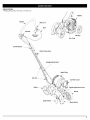 5
5
-
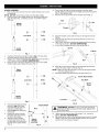 6
6
-
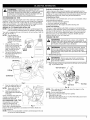 7
7
-
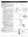 8
8
-
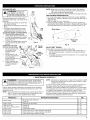 9
9
-
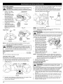 10
10
-
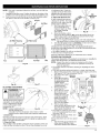 11
11
-
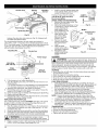 12
12
-
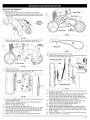 13
13
-
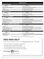 14
14
-
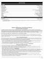 15
15
-
 16
16
-
 17
17
-
 18
18
-
 19
19
-
 20
20
-
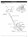 21
21
-
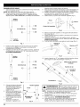 22
22
-
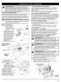 23
23
-
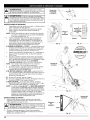 24
24
-
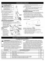 25
25
-
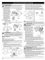 26
26
-
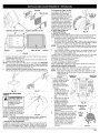 27
27
-
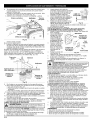 28
28
-
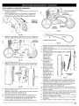 29
29
-
 30
30
-
 31
31
-
 32
32
-
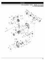 33
33
-
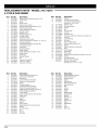 34
34
-
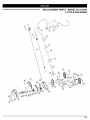 35
35
-
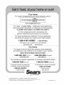 36
36


Craftsman 316.772370 Manual de usuario
- Tipo
- Manual de usuario
- Este manual también es adecuado para
En otros idiomas
- English: Craftsman 316.772370 User manual
Documentos relacionados
-
Craftsman 316.77237 Manual de usuario
-
-
MTD 316773800 El manual del propietario
-
-
-
-
-
-
-