Garant GridLine casing Instrucciones de operación
- Tipo
- Instrucciones de operación

GARANT GridLine Gehäuse
927300 - 927310, 927320, 927321, 927400 - 927420,
927600 - 927615, 927705 - 927725
Montageanleitung
Installation instructions | Instrucciones de montaje |
Instructions de montage | Istruzioni di montaggio |
Instrukcja montażu
UM0001014 Copyright © Hoffmann Group
Manufacturer
Hoffmann GmbH Qualitätswerkzeuge
Haberlandstr. 55, 81241 Munich, Germany
www.hoffmann-group.com
de
en
es
fr
it
pl
1
2
3
A
B
123
2✕
1
2⌀8✕32
M6✕10
C
1
⌀8✕32
D
1
2
3
4
E
de GridLine Gehäuse
1. Allgemeine Hinweise
Bedienungsanleitung lesen, beachten, für späteres Nachschlagen auf-
bewahren und jederzeit verfügbar halten.
2. Sicherheit
2.1 GRUNDLEGENDE SICHERHEITSHINWEISE
Kippende Werkbank
Verletzungsgefahr an Händen, Füßen und Körper durch ungesicherte, herabfallen-
de Gegenstände sowie Kippgefahr der Werkbank durch falsches Beladen.
» Fußschutz, Schutzhandschuhe tragen.
» Spitze oder andere Werkstücke nicht ungesichert lagern.
» Schwere Gegenstände in untere Schubladen lagern.
» Nicht mehrere Schubladen gleichzeitig öffnen.
» Bei Transport keine Gegenstände auf Arbeitsplatte legen.
» Schieben oder Transportieren nur mit geschlossenen, verriegelten Schubladen
und Schrankabteil.
» Maximale Tragfähigkeit der einzelnen Schubladen und Ablageböden beachten.
» Maximale Tragfähigkeit der Werkbank beachten.
» Bei Beladung je Schublade über 35 kg und Eigengewicht der Werkbank unter
150 kg, Werkbank im Boden verankern. Bodenverankerung über Hoffmann
Group Kundenservice beziehen.
2.2 BESTIMMUNGSGEMÄSSE VERWENDUNG
Größe 200 bis 500 und 800 bis 900 zur Montage an GridLine vario Werkbank.
Größe 600 und 700 zur Montage an GridLine Ready-to-go Werkbank.
Bis einschließlich Größe 500 in Kombination mit Fußteil montieren.
Ab Größe 800 ersetzt Gehäuse Fußteil. Höhe entsprechend gegenüberliegen-
dem Fußteil oder Gehäuse wählen.
Maximale Tragfähigkeiten beachten.
Schubladen zur Aufbewahrung von Werkzeugen.
Fachboden zur Aufbewahrung von Werkstücken und Werkzeugen.
Nur an entsprechenden Bohrungen montieren.
2.3 SACHWIDRIGER EINSATZ
Bodenstehendes Gehäuse nicht kombinierbar mit Seitenverkleidung und
Medienschiene.
2.4 PERSÖNLICHE SCHUTZAUSRÜSTUNG
Nationale und regionale Vorschriften zur Sicherheit und Unfallverhütung beach-
ten. Schutzkleidung wie Fußschutz und Schutzhandschuhe müssen entsprechend
der bei der jeweiligen Tätigkeit zu erwartenden Risiken gewählt und bereitgestellt
werden.
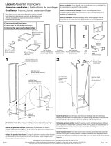
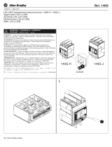
3. Montagehinweise
i
Gehäuse zur Montage auf linker oder rechter Seite. Arbeitsplatte mit zwei Personen
umdrehen und auf ebenen, sauberen Untergrund legen.
3.1 SCHUBLADEN AUSBAU
A
1. Schublade herausziehen.
2. Verriegelung herausziehen und nach oben drehen. Schublade entnehmen.
3.2 GEHÄUSE
3.2.1 Käfigmuttern einsetzen
B
i
Nur bei Gehäuse hängend beachten. Zwei Käfigmuttern am Kopfende des vorderen
Fußes in Ausstanzungen der Innenseite montieren.
1. Käfigmutter von vorne schräg, mit Längsseite, in Ausstanzung einsetzen.
2. Mit Schraubendreher nach hinten schieben, festklipsen.
3.2.2 Gehäuse montieren
C
/
D
i
Gehäuse entsprechend Bohrungen an Arbeitsplatte montieren.
1. Schubladen ausbauen (siehe Schubladen Ausbau [}1]) oder Tür öffnen.
2. Nur bei Gehäuse Größe 200 bis 500: Linsenkopf-Blechschrauben M6×10mm
mit Käfigmuttern in Fußteil verschrauben.
3. Gehäuse mit vier Unterlegscheiben und vier Sechskantschrauben Ø8×32mm
mit Arbeitsplatte verschrauben.
3.3 SCHUBLADEN EINBAU
E
1. Schubladenschienen herausziehen und festhalten.
2. Schublade einsetzen und bis Widerstand einfahren.
3. Schublade anheben und über Widerstand schieben bis Schublade komplett in
Schiene sitzt.
4. Verriegelung nach unten drehen und nach vorne schieben.
4. Technische Daten
i
Höhe des Gehäuses in mm entspricht Größenbezeichung (Beispiel Nr.930525400:
Höhe 400mm).
Gewicht
Artikelnummer Größe Leergewicht Mit Schubladen /
Tür / Schraub-
stock*
927300, 927412 300/2, 300 9,5kg 25kg
300/3 9,5kg 31kg
400/3, 400 11,5kg 34kg
400/4 11,5kg 40kg
600 15kg -
700 18kg -
800/4, 800 20kg 54kg
800/6 20kg 65kg
800/7 20kg 71kg
900/5, 900 22kg 63kg
900/6 22kg 69kg
900/7 22kg 75kg
927305 800/2 20kg 41kg
900/2 22kg 44kg
900/3 22kg 51kg
927310 600 15kg 21kg
700 18kg 24kg
800 20kg 27kg
900 22kg 33kg
927320*, 927321 600 15kg 30,3kg
700 18kg 33,3kg
800 20kg 35,3kg
900 22kg 37,3kg
927420 800/525 20kg 24kg
900/525 22kg 26kg
927600, 927720 200/1, 200 10kg 19kg
300/2, 300 11,5kg 30kg
300/3 11,5kg 37kg
400/4, 400 13,5kg 48kg
500/5, 500 15,5kg 59kg
600 18kg -
700 20kg -
800/4, 800 22kg 52kg
800/6 22kg 77kg
800/7 22kg 109kg
900/5, 900 24kg 74kg
900/6 24kg 81kg
900/7 24kg 88kg
927610 800/2 22kg 50kg
900/2 24kg 52kg
900/3 24kg 61kg
927615 600 18kg 26kg
700 20kg 28kg
800 22kg 31kg
900 24kg 34kg
927725 800/425 22kg 26kg
800/525 22kg 27kg
900/525 24kg 29kg
900/625 24kg 30kg
Maximale Tragfähigkeit Schubladen flächenverteilt
Artikelnummer Ohne Räder Mit Räder, fahrbar
927300 - 927310, 927320,
927321, 927400 - 927420,
927600 - 927615, 927705 -
927725
75kg 25kg
4.1 BELASTUNGSMATRIX
i
Belastungsangaben für GridLine vario Werkbänke mit Plattenlänge 1000 – 2000
mm.
Kombinationsmöglichkeiten Flächenverteilte, ruhende
Last
1×Arbeitsplatte
2×Fußteile
4×Knotenbleche
1×Arbeitsplatte
2×Fußteile
1×Gehäuse hängend
2×Knotenbleche
400 kg
1×Arbeitsplatte
2×Fußteile
2×Rückwand einzeln
2×Knotenbleche
1×Arbeitsplatte
2×Fußteile
1×Gehäuse hängend
2×Rückwand einzeln
1×Knotenblech
600 kg
1×Arbeitsplatte
1×Fußteil
1×Gehäuse bodenstehend
2x Knotenbleche
800 kg
1×Arbeitsplatte
2×Gehäuse bodenstehend
1000 kg
en GridLine casing
1. General instructions
Read the instructions for use, follow them and keep them available for
later reference.
2. Safety
2.1 ESSENTIAL SAFETY INSTRUCTIONS
Workbench tipping over
Risk of injury to hands, feet and body due to unrestrained objects falling and risk
of the workbench tipping over due to incorrect loading.
» Wear safety shoes and safety gloves.
» Do not store pointed or other workpieces without restraint.
» Store heavy objects in the bottom drawers.
» Do not open several drawers at once.
» Ensure during transport that no objects are present on the worktop.
» Ensure during movement and transport that all drawers and cupboard doors
are closed and locked.
» Comply with the maximum load capacity of the individual drawers and storage
shelves.
» Comply with the maximum load capacity of the workbench.
» If the load within each drawer exceeds 35kg and the tare weight of the work-
bench is less than 150kg, anchor the workbench to the floor. Order floor an-
choring from the Hoffmann Group Customer Service.
2.2 INTENDED USE
Size 200 to 500 and 800 to 900 for installation on a GridLine vario workbench.
Size 600 and 700 for installation on a GridLine Ready-to-go workbench.
For installation up to and including size 500 in conjunction with a support leg.
From size 800 the casing replaces the support leg. Select the height to corre-
spond to the opposite support leg or casing.
Comply with the maximum load capacity.
Drawers for storage of tools.
Storage shelf for storage of workpieces and tools.
Mount only on suitable holes.
2.3 REASONABLY FORESEEABLE MISUSE
A casing standing on the floor cannot be combined with side cladding and
media track.
2.4 PERSONAL PROTECTIVE EQUIPMENT
Comply with the national and regional regulations for safety and accident preven-
tion. Protective work wear such as safety shoes and safety gloves appropriate for
the risks associated with the intended activities must be selected and provided.
3. Installation instructions
i
Casing for installation on the left side or right side. Two persons working together
turn the worktop over and place it on a flat and clean support surface.
3.1 REMOVING THE DRAWERS
A
1. Pull out the drawer.
2. Pull out the locking mechanism and swing it upwards. Remove the drawer.
3.2 HOUSING
3.2.1 Use cage nuts
B
i
Applies only to a suspended casing. Fit two cage nuts at the head end of the front
leg into the punched holes on the inside.
1. Insert the cage nuts obliquely from the front with the long side in the pun-
ched recess.
2. Use a screwdriver to push them back and clip them securely into position.
3.2.2 Installing the casing
C
/
D
i
Install the casing using the pre-drilled holes on the worktop.
1. Remove the drawers (see Removing the drawers [}1]) or open the door.
2. Only for casing size 200 to 500: Screw M6×10mm raised-head self-tapping
screws into the cage nuts in the support leg.
3. Screw the casing to the worktop, using four plain washers and four
Ø8×32mm hex screws.
3.3 INSERTING THE DRAWERS
E
1. Pull the drawer runners out to their full extent and secure them.
2. Insert the drawer and push it in until you sense resistance.
3. Lift the drawer up and push it over the resistance until it is fully inserted on
the rails.
4. Swing the locking mechanism down and push it forwards.
4. Technical data
i
The height of the casing in mm is given by its size designation (for instance
No.930525400: height 400mm).
Weight
Article number Size Tare weight With drawers /
cupboard / vice*
927300, 927412 300/2, 300 9.5kg 25kg
300/3 9.5kg 31kg
400/3, 400 11.5kg 34kg
400/4 11.5kg 40kg
600 15kg -
700 18kg -
800/4, 800 20kg 54kg
800/6 20kg 65kg
800/7 20kg 71kg
900/5, 900 22kg 63kg
900/6 22kg 69kg
900/7 22kg 75kg
927305 800/2 20kg 41kg
900/2 22kg 44kg
900/3 22kg 51kg
927310 600 15kg 21kg
700 18kg 24kg
800 20kg 27kg
900 22kg 33kg
927320*, 927321 600 15kg 30.3kg
700 18kg 33.3kg
800 20kg 35.3kg
900 22kg 37.3kg
927420 800/525 20kg 24kg
900/525 22kg 26kg
927600, 927720 200/1, 200 10kg 19kg
300/2, 300 11.5kg 30kg
300/3 11.5kg 37kg
400/4, 400 13.5kg 48kg
500/5, 500 15.5kg 59kg
600 18kg -
700 20kg -
800/4, 800 22kg 52kg
800/6 22kg 77kg
800/7 22kg 109kg
900/5, 900 24kg 74kg
900/6 24kg 81kg
900/7 24kg 88kg
927610 800/2 22kg 50kg
900/2 24kg 52kg
900/3 24kg 61kg
927615 600 18kg 26kg
700 20kg 28kg
800 22kg 31kg
900 24kg 34kg
927725 800/425 22kg 26kg
800/525 22kg 27kg
900/525 24kg 29kg
900/625 24kg 30kg
Maximum load capacity of drawers, distributed
Article number Without wheels With wheels, mobile
927300 - 927310, 927320,
927321, 927400 - 927420,
927600 - 927615, 927705 -
927725
75kg 25kg
4.1 LOADING MATRIX
i
Loading data for GridLine vario workbenches with worktop length 1000 –
2000mm.
Available combinations Distributed non-dynamic
load
1×worktop
2×support legs
4×stabilising plates
1×worktop
2×support legs
1×suspended casing
2×stabilising plates
400 kg
1×worktop
2×support legs
2×rear panels
2×stabilising plates
1×worktop
2×support legs
1×suspended casing
2×individual rear pa-
nels
1×stabilising plate
600 kg
1×worktop
1×support leg
1×casing standing on the
floor
2×stabilising plates
800 kg
1×worktop
2×casings standing on the
floor
1000 kg
es Carcasa GridLine
1. Indicaciones generales
Lea, observe y conserve el manual de instrucciones de uso para consul-
tas posteriores, y téngalo siempre a mano.
2. Seguridad
2.1 INDICACIONES DE SEGURIDAD
Vuelco del banco de trabajo
Peligro de lesiones en manos, pies, y cuerpo por la caída de objetos sin protec-
ción, así como peligro de vuelco del banco de trabajo por carga incorrecta.
» Utilizar protección para los pies, guantes protectores.
» No guardar sin protección puntas u otras piezas de trabajo.
» Guardar los objetos pesados en los cajones inferiores.
» No abrir a la vez varios cajones.
» No colocar objetos en el tablero de trabajo durante el transporte.
» Desplazamiento o transporte solo con los cajones y el compartimento de arma-
rio cerrados y bloqueados.
» Tener en cuenta la capacidad de carga máxima de los distintos cajones y estan-
tes de almacenamiento.
» Tener en cuenta la capacidad de carga máxima del banco de trabajo.
» En caso de una carga de más de 35 kg por cajón y un peso propio del banco de
trabajo de menos de 150 kg, anclar el banco de trabajo en el suelo. Adquirir el
anclaje al suelo a través del Servicio de atención al cliente de Hoffmann Group.
2.2 USO CONFORME A LO PREVISTO
Tamaños 200 a 500 y 800 a 900 para el montaje en el banco de trabajo GridLi-
ne vario.
Tamaños 600 y 700 para el montaje en el banco de trabajo GridLine Ready-to-
go.
Hasta tamaño 500 incluido, montaje en combinación con un pie soporte.
A partir del tamaño 800, la carcasa sustituye al pie soporte. Elegir la altura con-
forme al pie soporte opuesto o la carcasa.
Tener en cuenta las capacidades de carga máximas.
Cajones para guardar herramientas.
Estante para guardar piezas de trabajo y herramientas.
Montar solo en las perforaciones correspondientes.
2.3 UTILIZACIÓN INDEBIDA
La carcasa colocada en el suelo no se puede combinar con el panel lateral y las
regletas para equipos multimedia.
2.4 EQUIPO DE PROTECCIÓN INDIVIDUAL
Tener en cuenta las normas nacionales y regionales en cuanto a seguridad y pre-
vención de accidentes. La ropa de protección como protección para los pies y
guantes protectores se han de seleccionar y disponer de acuerdo con los riesgos
propios de la actividad correspondiente.
3. Indicaciones para el montaje
i
Carcasa para el montaje en el lado izquierdo o derecho. Dar la vuelta al tablero de
trabajo entre dos personas y depositarlo en una superficie plana y limpia.
3.1 DESMONTAJE DE LOS CAJONES
A
1. Sacar el cajón superior.
2. Extraer el bloqueo y girarlo hacia arriba. Retirar el cajón.
3.2 CARCASA
3.2.1 Insertar las tuercas enjauladas
B
i
Observar únicamente en la carcasa colgante. Montar dos tuercas enjauladas en la
parte de la cabeza del pie delantero en el orificio troquelado en la superficie interior.
1. Colocar la tuerca de jaula oblicuamente por delante en el recorte.
2. Empujarla hacia atrás con un destornillador y engancharla.
3.2.2 Montar la carcasa
C
/
D
i
Montar la carcasa conforme a las perforaciones en el tablero de trabajo.
1. Desmontar los cajones (véase Desmontaje de los cajones [}1]) o abrir la
puerta.
2. Solo en la carcasa del tamaño 200 a 500: Atornillar tornillos alomados para
chapa M6×10mm con tuercas enjauladas en el pie soporte.
3. Atornillar la carcasa con cuatro arandelas y cuatro tornillos de cabeza hexago-
nal Ø8×32mm con el tablero de trabajo.
3.3 MONTAJE DE LOS CAJONES
E
1. Extraer y sujetar las guías de los cajones.
2. Insertar el cajón e introducirlo hasta percibir una resistencia.
3. Levantar el cajón y desplazarlo superando la resistencia hasta que se asiente
por completo en la guía.
4. Girar el bloqueo hacia abajo y empujarlo hacia delante.
4. Especificaciones técnicas
i
La altura de la carcasa en mm corresponde a la denominación del tamaño (ejem-
plo n.º930525400: altura 400mm).
Peso
Número de artícu-
lo
Tamaño Peso sin carga Con cajones / pu-
erta / tornillo de
banco*
927300, 927412 300/2, 300 9,5kg 25kg
300 / 3 9,5kg 31kg
400/3, 400 11,5kg 34kg
400 / 4 11,5kg 40kg
600 15kg -
700 18kg -
800/4, 800 20kg 54kg
800 / 6 20kg 65kg
800 / 7 20kg 71kg
900/5, 900 22kg 63kg
900 / 6 22kg 69kg
900 / 7 22kg 75kg
927305 800 / 2 20kg 41kg
900 / 2 22kg 44kg
900 / 3 22kg 51kg
927310 600 15kg 21kg
700 18kg 24kg
800 20kg 27kg
900 22kg 33kg
927320*, 927321 600 15kg 30,3kg
700 18kg 33,3kg
800 20kg 35,3kg
900 22kg 37,3kg
927420 800 / 525 20kg 24kg
900 / 525 22kg 26kg
927600, 927720 200/1, 200 10kg 19kg
300/2, 300 11,5kg 30kg
300 / 3 11,5kg 37kg
400/4, 400 13,5kg 48kg
500/5, 500 15,5kg 59kg
600 18kg -
700 20kg -
800/4, 800 22kg 52kg
800 / 6 22kg 77kg
800 / 7 22kg 109kg
900/5, 900 24kg 74kg
900 / 6 24kg 81kg
900 / 7 24kg 88kg
927610 800 / 2 22kg 50kg
900 / 2 24kg 52kg
900 / 3 24kg 61kg

Número de artícu-
lo
Tamaño Peso sin carga Con cajones / pu-
erta / tornillo de
banco*
927615 600 18kg 26kg
700 20kg 28kg
800 22kg 31kg
900 24kg 34kg
927725 800 / 425 22kg 26kg
800 / 525 22kg 27kg
900 / 525 24kg 29kg
900 / 625 24kg 30kg
Capacidad de carga máxima de los cajones distribuida por toda la superficie
Número de artículo Sin ruedas Con ruedas, transporta-
ble
927300 - 927310, 927320,
927321, 927400 - 927420,
927600 - 927615, 927705 -
927725
75kg 25kg
4.1 MATRIZ DE CARGA
i
Datos de carga para bancos de trabajo GridLine vario con longitud de tablero
1000-2000mm.
Posibilidades de combinación Caga distribuida en la super-
ficie, en reposo
1 tablero de trabajo
2 pies soporte
4 chapas de nudos
1 tablero de trabajo
2 pies soporte
1 carcasa suspendida
2 chapas de nudos
400kg
1 tablero de trabajo
2 pies soporte
2 paneles posteriores indi-
viduales
2 chapas de nudos
1 tablero de trabajo
2 pies soporte
1 carcasa suspendida
2 paneles posteriores
1 chapa de nudos
600kg
1 tablero de trabajo
1 pie soporte
1 carcasa apoyada en el
suelo
2 chapas de nudos
800kg
1 tablero de trabajo
2 carcasas apoyadas en el
suelo
1000kg
fr Bâtis GridLine
1. Remarques générales
Lisez, respectez et conservez le mode d'emploi à des fins de consultati-
on ultérieure, et gardez-le toujours à disposition.
2. Sécurité
2.1 CONSIGNES GÉNÉRALES DE SÉCURITÉ
Instabilité de l'établi
Risque de blessures au niveau des mains, des pieds et du corps en cas de chute
d'objets non sécurisés et risque de basculement de l'établi en cas de chargement
incorrect.
» Porter des gants et de chaussures de protection.
» Ne pas ranger de pièces pointues ni d'autres pièces non fixées.
» Ranger les objets lourds dans les tiroirs inférieurs.
» Ne pas ouvrir plusieurs tiroirs en même temps.
» Ne placer aucun objet sur le plan de travail pendant le transport.
» Procéder au déplacement ou au transport uniquement avec l'armoire intégrée
et les tiroirs fermés et verrouillés.
» Respecter la charge admissible maximale des différents tiroirs et tablettes.
» Respecter la charge admissible maximale de l'établi.
» En cas de chargement de plus de 35kg par tiroir et d'un poids propre de l'établi
inférieur à 150kg, ancrer l'établi au sol. Contacter le service clientèle de Hoff-
mannGroup pour l'ancrage au sol.
2.2 UTILISATION NORMALE
Réf. 200 à 500 et 800 à 900 pour montage sur un établi GridLine vario.
Réf. 600 et 700 pour montage sur un établi GridLine Ready-to-go.
Jusqu'à la réf. 500 incluse, monter en association avec un piètement.
A partir de la réf. 800, le bâti remplace le piètement. Choisir une hauteur corre-
spondant au bâti ou au piètement opposé.
Respecter les charges admissibles maximales.
Tiroirs pour le rangement d'outils.
Tablette pour le rangement de pièces et d'outils.
Monter uniquement sur les trous correspondants.
2.3 MAUVAIS USAGE RAISONNABLEMENT PRÉVISIBLE
Les bâtis au sol ne sont pas combinables avec une paroi latérale ni avec un rail
d'alimentation.
2.4 EQUIPEMENT DE PROTECTION INDIVIDUELLE
Respecter les réglementations nationales et régionales en matière de sécurité et
de prévention des accidents. Les vêtements de protection, tels que les chaussures
et les gants, doivent être choisis et mis à disposition en fonction des risques
prévus pendant l'activité concernée.
3. Consignes de montage
i
Bâti pour montage du côté gauche ou du côté droit. Retourner le plan de travail
avec l'aide de deux personnes et le poser sur une surface plane et propre.
3.1 DÉMONTAGE DES TIROIRS
A
1. Extraire le tiroir.
2. Extraire le dispositif de verrouillage et le tourner vers le haut. Retirer le tiroir.
3.2 BÂTI
3.2.1 Mise en place des écrous cage
B
i
Uniquement pertinent pour les bâtis suspendus. Monter deux écrous cage en haut
du pied avant dans les découpes de la paroi intérieure.
1. Insérer l'écrou cage dans la découpe par l'avant en oblique, avec le côté long.
2. Pousser vers l'arrière à l'aide d'un tournevis, clipser fermement.
3.2.2 Montage du bâti
C
/
D
i
Monter le bâti au plan de travail selon les trous correspondants.
1. Démonter les tiroirs (voir Démontage des tiroirs [}2]) ou ouvrir la porte.
2. Uniquement pour les bâtis réf. 200 à 500: serrer les vis à tôle à tête bombée
M6×10mm aux écrous cage dans le piètement.
3. Visser le bâti au plan de travail à l'aide de quatre rondelles et de quatre vis à
6pans Ø8×32mm.
3.3 MONTAGE DES TIROIRS
E
1. Extraire les rails de tiroir et les retenir.
2. Mettre en place le tiroir et l'insérer jusqu'à sentir une résistance.
3. Soulever le tiroir et le pousser au-delà de la résistance jusqu'à ce qu'il soit
complètement dans le rail.
4. Tourner le dispositif de verrouillage vers le bas et le pousser vers l'avant.
4. Caractéristiques techniques
i
La hauteur du bâti en mm correspond à la référence (par exemple930525400:
hauteur 400mm).
Poids
Code article Réf. Poids à vide Avec tiroirs/por-
te/étau*
927300, 927412 300/2, 300 9,5kg 25kg
300/3 9,5kg 31kg
400/3, 400 11,5kg 34kg
400/4 11,5kg 40kg
600 15kg -
700 18kg -
800/4, 800 20kg 54kg
800/6 20kg 65kg
800/7 20kg 71kg
900/5, 900 22kg 63kg
900/6 22kg 69kg
900/7 22kg 75kg
927305 800/2 20kg 41kg
900/2 22kg 44kg
900/3 22kg 51kg
927310 600 15kg 21kg
700 18kg 24kg
800 20kg 27kg
900 22kg 33kg
927320*, 927321 600 15kg 30,3kg
700 18kg 33,3kg
800 20kg 35,3kg
900 22kg 37,3kg
927420 800/525 20kg 24kg
900/525 22kg 26kg
927600, 927720 200/1, 200 10kg 19kg
300/2, 300 11,5kg 30kg
300/3 11,5kg 37kg
400/4, 400 13,5kg 48kg
500/5, 500 15,5kg 59kg
600 18kg -
700 20kg -
800/4, 800 22kg 52kg
Code article Réf. Poids à vide Avec tiroirs/por-
te/étau*
800/6 22kg 77kg
800/7 22kg 109kg
900/5, 900 24kg 74kg
900/6 24kg 81kg
900/7 24kg 88kg
927610 800/2 22kg 50kg
900/2 24kg 52kg
900/3 24kg 61kg
927615 600 18kg 26kg
700 20kg 28kg
800 22kg 31kg
900 24kg 34kg
927725 800/425 22kg 26kg
800/525 22kg 27kg
900/525 24kg 29kg
900/625 24kg 30kg
Charge admissible maximale des tiroirs uniformément répartie
Code article Sans roues Avec roues, mobile
927300 - 927310, 927320,
927321, 927400 - 927420,
927600 - 927615, 927705 -
927725
75kg 25kg
4.1 TABLEAU DES CHARGES
i
Indications de charge pour les établis GridLine vario avec longueur de plan de
travail de 1000 – 2000mm.
Possibilités de combinaisons Charge statique, uniformé-
ment répartie
1×plan de travail
2×piètements
4×goussets
1×plan de travail
2×piètements
1×caisson suspendu
2×goussets
400kg
1×plan de travail
2×piètements
2×parois arrière individu-
elles
2×goussets
1×plan de travail
2×piètements
1×caisson suspendu
2×parois arrière indi-
viduelles
1×gousset
600kg
1×plan de travail
1×piètement
1×caisson au sol
2×goussets
800kg
1×plan de travail
2×caissons au sol
1000kg
it Alloggiamento GridLine
1. Note generali
Leggere il manuale d’uso, rispettarlo, conservarlo per riferimento futuro
e tenerlo sempre a portata di mano.
2. Sicurezza
2.1 AVVERTENZE FONDAMENTALI PER LA SICUREZZA
Caduta del banco da lavoro
Pericolo di lesioni a mani, piedi e altre parti del corpo legato alla caduta di oggetti
non fissati e pericolo di ribaltamento del banco da lavoro dovuto a un caricamen-
to errato.
» Indossare scarpe di sicurezza e guanti protettivi.
» Fissare sempre i pezzi appuntiti o altri oggetti.
» Conservare gli oggetti pesanti nei cassetti inferiori.
» Non aprire più cassetti contemporaneamente.
» In caso di trasporto, non appoggiare alcun oggetto sopra il piano di lavoro.
» Spostare o trasportare il banco da lavoro solo con i cassetti e l’armadietto debit-
amente chiusi e bloccati.
» Rispettare la portata massima dei singoli cassetti e delle singole mensole.
» Rispettare la portata massima del banco da lavoro.
» Con carico superiore a 35 kg a cassetto e peso proprio del banco da lavoro infe-
riore a 150 kg, ancorare il banco stesso al pavimento. Acquistare l'ancoraggio al
pavimento rivolgendosi al servizio clienti di Hoffmann Group.
2.2 USO PREVISTO
Dim. da 200 a 500 e da 800 a 900 per il montaggio sul banco da lavoro GridLine
vario.
Dim. 600 e 700 per il montaggio sul banco da lavoro GridLine Ready-to-go.
Fino alla dim. 500 inclusa, montaggio in combinazione con strutture portanti.
A partire dalla dim. 800, l'alloggiamento sostituisce le strutture portanti.
Scegliere l'altezza in funzione alle strutture portanti contrapposte o all'allog-
giamento.
Rispettare la portata massima prevista.
Cassetti per la custodia degli utensili.
Ripiano per la custodia di pezzi e utensili.
Montare solo nei fori corrispondenti.
2.3 USO SCORRETTO RAGIONEVOLMENTE PREVEDIBILE
Alloggiamento a pavimento non abbinabile al rivestimento laterale e alla barra
portaprese.
2.4 DISPOSITIVI DI PROTEZIONE ANTINFORTUNISTICI
Osservare le norme nazionali e regionali in materia di sicurezza e prevenzione
degli infortuni. L’abbigliamento di protezione, come scarpe di sicurezza e guanti
protettivi, deve essere selezionato e messo a disposizione conformemente ai ri-
schi legati alla rispettiva attività.
3. Indicazioni di montaggio
i
Alloggiamento per il montaggio sul lato sinistro o destro. Capovolgere il piano di
lavoro con l’aiuto di due persone e appoggiarlo su una superficie piana e pulita.
3.1 SMONTAGGIO DEI CASSETTI
A
1. Estrarre il cassetto.
2. Estrarre il dispositivo di bloccaggio e girarlo verso l'alto. Rimuovere il cassetto.
3.2 ALLOGGIAMENTO
3.2.1 Inserimento dei dadi in gabbia
B
i
Solo con alloggiamento appeso. Montare due dadi in gabbia sull'estremità superio-
re del piedino anteriore nelle scanalature del lato interno.
1. Montare il dado in gabbia nella punzonatura inserendolo da davanti in posi-
zione obliqua dal lato lungo.
2. Spingerlo all’indietro con l’aiuto di un giravite e fissarlo mediante le clip di ag-
gancio.
3.2.2 Montaggio dell'alloggiamento
C
/
D
i
Montare l'alloggiamento in base alla disposizione dei fori sul piano di lavoro.
1. Smontare i cassetti (vedi Smontaggio dei cassetti [}2]) o aprire lo sportel-
lo.
2. Solo con alloggiamento da dim. 200 a 500: avvitare le viti autofilettanti a testa
bombata M6×10mm con dadi in gabbia nelle strutture portanti.
3. Avvitare l'alloggiamento al piano di lavoro con quattro rondelle e quattro viti
esagonali Ø8×32mm.
3.3 MONTAGGIO DEI CASSETTI
E
1. Estrarre le guide dei cassetti e bloccarle.
2. Inserire il cassetto e spingerlo finché non si incontra una certa resistenza.
3. Sollevare il cassetto e farlo scorrere attraverso la resistenza finché non risul-
terà completamente inserito nella guida.
4. Girare il bloccaggio verso il basso e spingerlo in avanti.
4. Dati tecnici
i
L'altezza dell'alloggiamento in mm corrisponde alla designazione della misura (ad
esempio n.930525400: altezza 400mm).
Peso
Numero articolo Dim. Peso a vuoto Con cassetti /
sportello / morsa*
927300, 927412 300/2, 300 9,5kg 25kg
300/3 9,5kg 31kg
400/3, 400 11,5kg 34kg
400/4 11,5kg 40kg
600 15kg -
700 18kg -
800/4, 800 20kg 54kg
800/6 20kg 65kg
800/7 20kg 71kg
900/5, 900 22kg 63kg
900/6 22kg 69kg
900/7 22kg 75kg
927305 800/2 20kg 41kg
900/2 22kg 44kg
900/3 22kg 51kg
927310 600 15kg 21kg
700 18kg 24kg
800 20kg 27kg
900 22kg 33kg
927320*, 927321 600 15kg 30,3kg
700 18kg 33,3kg
800 20kg 35,3kg
900 22kg 37,3kg
Numero articolo Dim. Peso a vuoto Con cassetti /
sportello / morsa*
927420 800/525 20kg 24kg
900/525 22kg 26kg
927600, 927720 200/1, 200 10kg 19kg
300/2, 300 11,5kg 30kg
300/3 11,5kg 37kg
400/4, 400 13,5kg 48kg
500/5, 500 15,5kg 59kg
600 18kg -
700 20kg -
800/4, 800 22kg 52kg
800/6 22kg 77kg
800/7 22kg 109kg
900/5, 900 24kg 74kg
900/6 24kg 81kg
900/7 24kg 88kg
927610 800/2 22kg 50kg
900/2 24kg 52kg
900/3 24kg 61kg
927615 600 18kg 26kg
700 20kg 28kg
800 22kg 31kg
900 24kg 34kg
927725 800/425 22kg 26kg
800/525 22kg 27kg
900/525 24kg 29kg
900/625 24kg 30kg
Portata massima dei cassetti distribuita su tutta la superficie
Numero articolo Senza ruote Con ruote, mobile
927300 - 927310, 927320,
927321, 927400 - 927420,
927600 - 927615, 927705 -
927725
75kg 25kg
4.1 MATRICE DI CARICO
i
Indicazioni relative al carico per i banchi da lavoro GridLine vario con lunghezza
del piano compresa tra 1.000 e 2.000 mm.
Possibili combinazioni Carico statico ripartito su tut-
ta la superficie
1× piano di lavoro
2× strutture portanti
4× raccordi a gomito
1× piano di lavoro
2× strutture portanti
1× alloggiamento ap-
peso
2× raccordi a gomito
400 kg
1× piano di lavoro
2× strutture portanti
2× pareti posteriori singo-
le
2× raccordi a gomito
1× piano di lavoro
2× strutture portanti
1× alloggiamento ap-
peso
2× pareti posteriori
singole
1× raccordo a gomito
600 kg
1× piano di lavoro
1× struttura portante
1× corpo poggiato a terra
2× raccordi a gomito
800 kg
1× piano di lavoro
2× corpi poggiati a terra
1.000 kg
pl Obudowa GridLine
1. Informacje ogólne
Należy zapoznać się z instrukcją obsługi i przestrzegać jej oraz zacho-
wać ją na przyszłość, przechowując w dostępnym miejscu.
2. Bezpieczeństwo
2.1 PODSTAWOWE INSTRUKCJE BEZPIECZEŃSTWA
Przewracający się stół warsztatowy
Niebezpieczeństwo odniesienia obrażeń dłoni, stóp iciała stwarzane przez niez-
abezpieczone spadające przedmioty oraz przewracający się stół warsztatowy
wskutek nieprawidłowego załadunku.
» Nosić ochronę stóp irękawice ochronne.
» Nie przechowywać niezabezpieczonych ostrych lub innych detali.
» Ciężkie przedmioty należy przechowywać wdolnych szufladach.
» Nie otwierać jednocześnie kilku szuflad.
» Podczas transportu nie odkładać na blat roboczy żadnych przedmiotów.
» Przesuwać lub transportować stół tylko po zamknięciu izablokowaniu szuflad
oraz części szafkowej.
» Pamiętać omaksymalnej nośności poszczególnych szuflad ipółek.
» Przestrzegać maksymalnej nośności stołu warsztatowego.
» Przy załadunku szuflady przekraczającym 35kg iciężarze własnym stołu roboc-
zego poniżej 150kg należy zakotwić stół warsztatowy wpodłodze. Kotwy po-
dłogowe zamawiać za pośrednictwem serwisu klienta Hoffmann Group.
2.2 UŻYTKOWANIE ZGODNIE ZPRZEZNACZENIEM
Rozmiar od 200 do 500 iod 800 do 900 do montażu na stole warsztatowym
GridLine vario.
Rozmiar 600 i700 do montażu na stole warsztatowym GridLine Ready-to-go.
Włącznie do rozm. 500 montować wpołączeniu zsegmentem nóg.
Od rozm. 800 obudowa zastępuje segment nóg. Wysokość należy dobierać
stosownie do przeciwległego segmentu nóg lub obudowy.
Uwzględnić maksymalną nośność.
Szuflady do przechowywania narzędzi.
Półki do przechowywania obrabianych przedmiotów inarzędzi.
Montować wyłącznie we właściwych otworach.
2.3 NIEWŁAŚCIWE UŻYTKOWANIE
Obudowy stojącej nie łączyć zobudową boczną iszyną mediów.
2.4 ŚRODKI OCHRONY INDYWIDUALNEJ
Przestrzegać krajowych iregionalnych przepisów dotyczących bezpieczeństwa
izapobiegania nieszczęśliwym wypadkom. Należy dobrać iudostępnić odzież
ochronną, taką jak ochrona stóp irękawice ochronne, odpowiednio do rodzajów
ryzyka oczekiwanego podczas wykonywania danej czynności.
3. Wskazówki dotyczące montażu
i
Obudowa do montażu po lewej lub prawej stronie. Dwie osoby muszą obrócić blat
roboczy iułożyć go na równym iczystym podłożu.
3.1 DEMONTAŻ SZUFLAD
A
1. Wysunąć szufladę.
2. Wyciągnąć blokadę iobrócić do góry. Wyjąć szufladę.
3.2 OBUDOWA
3.2.1 Nakładanie nakrętek klatkowych
B
i
Przestrzegać tylko wprzypadku obudowy wiszącej. Dwie nakrętki klatkowe zamo-
cować na górnej krawędzi przedniej nogi wwycięciu po wewnętrznej stronie.
1. Nakrętkę klatkową włożyć ukośnie od przodu długą stroną w wycięcie.
2. Korzystając z wkrętaka przesunąć do tyłu i zatrzasnąć.
3.2.2 Montaż obudowy
C
/
D
i
Zamontować obudowę stosownie do otworów wblacie roboczym.
1. Wymontować szuflady (patrz Demontaż szuflad [}2]) lub otworzyć drzwi.
2. Tylko wprzypadku obudowy wrozmiarze od 200 do 500: przykręcić śruby
złbem soczewkowym M6x10mm do segmentu nóg, używając nakrętek klat-
kowych.
3. Przykręcić obudowę do blatu roboczego, używając czterech podkładek iczte-
rech śrub złbem sześciokątnym Ø8×32mm.
3.3 MONTAŻ SZUFLAD
E
1. Wysunąć iprzytrzymać prowadnice szynowe szuflad.
2. Założyć szufladę iwsunąć do oporu.
3. Podnieść szufladę iprzesuwać do oporu, aż znajdzie się wcałości wszynie.
4. Obrócić blokadę wdół iprzesunąć do przodu.
4. Dane techniczne
i
Wysokość obudowy wmm odpowiada oznaczeniu rozmiaru (przykład
nr930525400: wysokość 400mm).
Masa
Numer artykułu Rozmiar Masa własna Zszufladami /
drzwiami / ima-
dłem*
927300, 927412 300/2, 300 9,5kg 25kg
300/3 9,5kg 31kg
400/3, 400 11,5kg 34kg
400/4 11,5kg 40kg
600 15kg -
700 18kg -
800/4, 800 20kg 54kg
800/6 20kg 65kg
800/7 20kg 71kg
900/5, 900 22kg 63kg
900/6 22kg 69kg
900/7 22kg 75kg
927305 800/2 20kg 41kg
900/2 22kg 44kg
900/3 22kg 51kg
Numer artykułu Rozmiar Masa własna Zszufladami /
drzwiami / ima-
dłem*
927310 600 15kg 21kg
700 18kg 24kg
800 20kg 27kg
900 22kg 33kg
927320*, 927321 600 15kg 30,3kg
700 18kg 33,3kg
800 20kg 35,3kg
900 22kg 37,3kg
927420 800/525 20kg 24kg
900/525 22kg 26kg
927600, 927720 200/1, 200 10kg 19kg
300/2, 300 11,5kg 30kg
300/3 11,5kg 37kg
400/4, 400 13,5kg 48kg
500/5, 500 15,5kg 59kg
600 18kg -
700 20kg -
800/4, 800 22kg 52kg
800/6 22kg 77kg
800/7 22kg 109kg
900/5, 900 24kg 74kg
900/6 24kg 81kg
900/7 24kg 88kg
927610 800/2 22kg 50kg
900/2 24kg 52kg
900/3 24kg 61kg
927615 600 18kg 26kg
700 20kg 28kg
800 22kg 31kg
900 24kg 34kg
927725 800/425 22kg 26kg
800/525 22kg 27kg
900/525 24kg 29kg
900/625 24kg 30kg
Maksymalna nośność powierzchniowa szuflad
Numer artykułu Bez kółek Na kółkach, przejezdna
927300–927310, 927320,
927321, 927400–927420,
927600–927615, 927705–
927725
75kg 25kg
4.1 ZESTAWIENIE OBCIĄŻEŃ
i
Wartości obciążeń dla stołów warsztatowych GridLine vario o długości blatu
1000–2000 mm.
Możliwe kombinacje Obciążenie statyczne, po-
wierzchniowe
1×blat roboczy
2×segment nóg
4×węzłówka
1×blat roboczy
2×segment nóg
1×obudowa wisząca
2×węzłówka
400 kg
1×blat roboczy
2×segment nóg
2לcianka tylna pojedyn-
cza
2×węzłówka
1×blat roboczy
2×segment nóg
1×obudowa wisząca
2לcianka tylna poje-
dyncza
1×węzłówka
600 kg
1×blat roboczy
1×segment nóg
1×obudowa wisząca
2x węzłówka
800 kg
1×blat roboczy
2×obudowa stojąca
1000 kg
-
 1
1
-
 2
2


Garant GridLine casing Instrucciones de operación
- Tipo
- Instrucciones de operación
en otros idiomas
Artículos relacionados
Otros documentos
-
 Hirsh Industries 21899 Assembly Instructions
-
ROSIERES CEN 126 IN El manual del propietario
-
 Varec Series 5000/5010 Flame arresters El manual del propietario
-
Dwyer Series V4 Manual de usuario
-
Airforce Domino POP 30 Manual de usuario
-
 Allen-Bradley 140G-J Guía de inicio rápido
-
Amazon Basics B01N4Q9FZR Manual de usuario
-
Miller MAXSTAR 350 ALL OTHER CE AND NON-CE MODELS El manual del propietario


