LG LW2410HR El manual del propietario
- Tipo
- El manual del propietario

OWNER’S MANUAL
AIR CONDITIONER
Please read this manual carefully before operating
your set and retain it for future reference.
P/NO:0)/
www.lgappliances.com
TYPE:WINDOW
MODELS:LW1810HR,LW2410HR

2 Room Air Conditioner
Window-Type Air Conditioner Owner’s Manual
TABLE OF CONTENTS
FOR YOUR RECORDS
Write the model and serial numbers here:
Model #
Serial #
You can find them on a label on the side of each unit.
Dealer's Name
Date Purchased
■ Staple your receipt to this page in the event you need it
to prove date of purchase or for warranty issues.
READ THIS MANUAL
Inside you will find many helpful hints on how to use and
maintain your air conditioner properly. Just a little preventive
care on your part can save you a great deal of time and
money over the life of your air conditioner.
You'll find many answers to common problems in the chart
of troubleshooting tips. If you review our chart of
Troubleshooting Tips first, you may not need to call for
service at all.
PRECAUTION
• Contact the authorized service technician for repair
or maintenance of this unit.
• Contact the installer for installation of this unit.
• The air conditioner is not intended for use by young
children or invalids without supervision.
• Young children should be supervised to ensure that
they do not play with the air conditioner.
• When the power cord is to be replaced, replacement
work shall be performed by authorized personnel only
using only genuine replacement parts.
• Installation work must be performed in accordance
with the National Electric Code by qualified and
authorized personnel only.
Safety Precautions..........................3
Before Operation.............................7
Introduction ....................................8
Electrical Safety ..............................9
Installation ....................................11
Operating Instructions .................16
Maintenance and Service ............20


Before Operation
Owner’s Manual 7
ENGLISH
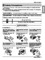
Before Operation
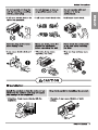
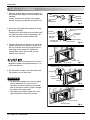
1. Contact an installation specialist for installation.
2. Plug in the power plug properly.
3. Use a dedicated circuit.
4. Do not use an extension cord.
5. Do not start/stop operation by plugging/unplugging the power cord.
6. If the cord/plug is damaged, replace it with only an authorized replacement
part.
1. Being exposed to direct airflow for an extended period of time could be
hazardous to your health. Do not expose occupants, pets, or plants to direct
airflow for extended periods of time.
2. Due to the possibility of oxygen deficiency, ventilate the room when used
together with stoves or other heating devices.
3. Do not use this air conditioner for non-specified special purposes (e.g.
preserving precision devices, food, pets, plants, and art objects). Such usage
could damage the items.
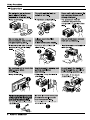
1. Do not touch the metal parts of the unit when removing the filter. Injuries can
occur when handling sharp metal edges.
2. Do not use water to clean inside the air conditioner. Exposure to water can
destroy the insulation, leading to possible electric shock.
3. When cleaning the unit, first make sure that the power and breaker are turned
off. The fan rotates at a very high speed during operation. There is a
possibility of injury if the unit’s power is accidentally triggered on while
cleaning inner parts of the unit.
For repair and maintenance, contact your authorized service dealer.
Preparing for Operation
Usage
Cleaning and Maintenance
Service

8 Room Air Conditioner
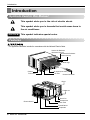
Introduction
This symbol alerts you to the risk of electric shock.
This symbol alerts you to hazards that could cause harm to
the air conditioner.
This symbol indicates special notes.
NOTICE
This appliance should be installed in accordance with the National Electric Code.
Introduction
Symbols Used in this Manual
Features
Evaporator
Electric Heater
Control Board
Brace
Vertical Air Deflector
(Horizontal Louver)
Horizontal Air Deflector
(Vertical Louver)
Air Discharge
Cabinet
Front Grille Air Filter
Air Intake(Inlet Grille)
Condenser
Base Pan
Compressor
Power Cord
Remote Controller

Electrical Safety
Owner’s Manual 9
ENGLISH
Electrical Safety
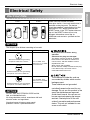
Electrical Data
115V~ 230V~
Power cord may include a current
interrupter device. A test and reset button is
provided on the plug case. The device
should be tested on a periodic basis by first
pressing the TEST button and then the
RESET button. If the TEST button does not
trip or if the RESET button will not stay
engaged, discontinue use of the air
conditioner and contact a qualified service
technician.
Use Wall Receptacle Power Supply
Standard 125V, 3-wire grounding
receptacle rated 15A, 125V AC
Standard 250V, 3-wire grounding
receptacle rated 15A, 250V AC
Use 15 AMP. time
delay fuse or 15 AMP.
circuit breaker.
Use 20 AMP. time
delay fuse or 20 AMP.
circuit breaker.
Standard 250V, 3-wire grounding
receptacle rated 20A, 250V AC
Never push the test button during
operation
Otherwise this plug can damaged.
This device contains chemical, including
lead, known to the State of California to
cause cancer, and birth defects or other
reproductive harm.
Wash hands after handling.
Do not remove, modify or immerse this plug.
If this device trips, the cause it to be
corrected before further use.
The conductors inside this cord are
surrounded by shields, which monitor
leakage current.
These shields are not grounded.
<
Periodically examine the cord for any
damage. Do not use this product in the
event the shields become exposed.
Avoid shock hazard, this unit can not
be user serviced opening the tamper
resistant. Sealed portion of the unit
voids all warranties and performance
claims. This unit not intended for use
as an on-off switch.
The shape may be different according to its model.
NOTICE
DO NOT USE AN EXTENSION CORD on 230,
208, and 230/208 Volt units.
All wiring should be made in accordance with local
electrical codes and regulations.
Aluminum house wiring may pose special
problems. Consult a qualified electrician.
NOTICE

10 Room Air Conditioner
Electrical Safety
Electrical Safety
IMPORTANT
(PLEASE READ CAREFULLY)
FOR THE USER'S PERSONAL SAFETY, THIS
APPLIANCE MUST BE PROPERLY GROUNDED
The power cord of this appliance is equipped with a
three-prong (grounding) plug. Use this with a standard
three-slot (grounding) wall power outlet to minimize the
hazard of electric shock. The customer should have the
wall receptacle and circuit checked by a qualified
electrician to make sure the receptacle is properly
grounded.
DO NOT CUT OR REMOVE THE THIRD (GROUND)
PRONG FROM THE POWER PLUG.
A. SITUATIONS WHEN THE APPLIANCE WILL BE
DISCONNECTED OCCASIONALLY:
Because of potential safety hazards, we strongly
discourage the use of an adapter plug. However, if you
wish to use an adapter, a TEMPORARY CONNECTION
may be made. Use UL-listed adapter, available from
most local hardware stores.
The large slot in the adapter must be aligned with the
large slot in the receptacle to assure a proper polarity
connection.
:
Attaching the adapter ground terminal to the wall
receptacle cover screw does not ground the appliance
unless the cover screw is metal, and not insulated, and
the wall receptacle is grounded through the house
wiring. The customer should have the circuit checked
by a qualified electrician to make sure the receptacle
is properly grounded.
Disconnect the power cord from the adapter, using one
hand on each. Otherwise, the adapter ground terminal
might break. DO NOT USE the appliance with a broken
adapter plug.
B. SITUATIONS WHEN THE APPLIANCE WILL BE
DISCONNECTED OFTEN.
Do not use an adapter plug in these situations.
Unplugging the power cord frequently can lead to an
eventual breakage of the ground terminal. The wall
power outlet should be replaced by a three-slot
(grounding) outlet instead.
USE OF EXTENSION CORDS
Because of potential safety hazards, we strongly
discourage the use of an extension cord. However, if
you wish to use an extension cord, use a CSA
certified/UL-listed 3-wire (grounding) extension cord,
rated at 20A, 250V.

Owner’s Manual 11
ENGLISH
Installation
Installation
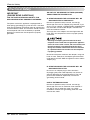
How to Install the Unit
How to Use the Reversible Inlet Grille(For Some Models)
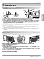
1. To avoid vibration and noise, make sure the unit is installed securely and firmly.
2. Install the unit where the sunlight does not shine directly on the unit.
If the unit receives direct sunlight, build an awning to shade the cabinet.
3. There should be no obstacle, like a fence, within 20” which might restrict heat radiation from the condenser.
4. To prevent reducing performance, install the unit so that louvers of the cabinet are not blocked.
5. Install the unit a little obliquely outward not to avoid leaking the condensed water into the room (about 1/2”
or 1/4 bubble with level).
6. Install the unit with its bottom portion 30~60” above the floor level.
7. Stuff the foam between the top of the unit and the wall to prevent air and insects from getting into the room.
8. The power cord must be connected to an independent circuit. The green wire must be grounded.
9. Connect the drain tube to the base pan hole in the rear side if you need to drain (consult a dealer.)
Plastic hose or equivalent may be connected to the drain tube.
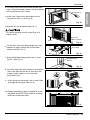
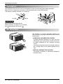
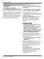
The grille is designed to clean the filter both upward and downward.
A. Before attaching the front grille to the cabinet, if you want to pull out the filter upward;
1. Open the inlet grille slightly (a).
2. Turn inside out the front grille (a).
3. Disassemble the inlet grille from the front grille with separating the hinged part by inserting a straight type
screw-driver tip (b).
4. Then, rotate the inlet grille 180 degrees and insert the hooks into bottom holes of the front grille.
5. Insert the filter and attach the front grille to the cabinet.
B. If you want to pull out the filter downward;
The grille is already designed that way.
About 1/2"
Over 20"
HEAT
RADIATION
FENCE
AWNING
INSIDE OUTSIDE
FOAM
COOLED
AIR
30-60"
Level
1/4 Bubble
(b)
b
(a) (c)

12 Room Air Conditioner
Installation
Window Requirements
Installation Kits Contents
All supporting parts should be secured to firm wood, masonry,
or metal.
1. This unit is designed for installation in standard double hung
windows with actual opening widths from 29" to 41".
The top and bottom window sashes must open sufficiently to
allow a clear vertical opening of 18" from the bottom of the
upper sash to the window stool.
2. The stool offset (height between the stool and sill) must be
less than 1 1/4".
NOTICE
29" to 41"
18" min
Offset
Less
than 1
1
/4"
Sill
Exterior
Interior wall
26" min.
(Without frame curtain)
Stool
Foam-PE
(Adhesive-Backed)
Type C (5) Type D (2)
Type A (11)
Carriage Bolt (2) Lock Nut (4)
Type B (7)
Foam strip
(Plain-Back)
Right frame
curtain
Window locking
bracket
Left frame
curtain
Frame guide(2)
Sill
bracket
(2)
Support bracket(2)
Drain joint pipe

Owner’s Manual 13
ENGLISH
Installation
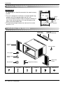
Suggested Tool Requirements
SCREWDRIVER(+, -), RULER, KNIFE, HAMMER, PENCIL, LEVEL
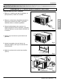
PREPARATION OF CHASSIS
1. Remove the screws which fasten the cabinet at
both sides and at the back.
2. Slide the unit out from the cabinet by gripping
the base pan handle and pulling forward while
bracing the cabinet.
3. Cut the window sash seal to the proper length.
Peel off the backing and attach the Foam-PE to
the underside of the window sash.
4.
5.
6.
Insert the Frame guides into the bottom of the
cabinet.
Insert the Frame Curtain into the Top retainer bar
and Frame guides.
Fasten the curtains to the unit with 10 screws
(Type A) at both sides.
Foam-PE
Top retainer bar
Screw
(Type A)
Screw(Type A)
Frame guide
Shipping screws
Fig. 1
Fig. 2
Fig. 3
Fig. 4

14 Room Air Conditioner
Installation
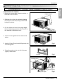
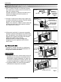
Cabinet Installation
1. Open the window. Mark a line on the center of
the window stool between the side window stop
moldings.
Loosely attach the sill bracket to the support
bracket using the carriage bolt and the lock nut.
2. Attach the sill bracket to the window sill using
the screws (Type B).
Carefully place the cabinet on the window stool
and align the center mark on the bottom front
with the center line marked window stool.
3. Using the M-screw and the lock nut, attach the
support bracket to the cabinet track hole. Use
the first track hole after the sill bracket on the
outer edge of the window sill. Tighten the
carriage bolt and the lock nut. Be sure the
cabinet slants outward.
Do not drill a hole in the bottom pan. The unit is
designed to operate with approximately 1/2" of
water in bottom pan.
4. Pull the bottom window sash down behind the
Top retainer bar until they meet.
1. Do not pull the window sash down so tightly
that the movement of Frame curtain is
restricted. Attach the cabinet to the window
stool by driving the screws (Type B) through
the cabinet into window stool.
2. The cabinet should be installed with a very
slight tilt downward toward the outside.
NOTICE
Support
Bracket
Lock nut
Sill
Bracket
Carriage
Bolt
(M-Screw)
Front angle
Window stool
Window sash
Top retainer bar
Cabinet
Foam-PE
Frame curtain
Screw(Type B)
Front Angle
Sash track
Foam-PE
Cabinet
Track hole
Support
Bracket
Carriage bolt
and lock nut
Machine screw(Type D)
and lock nut
Outer edge
of window
sill
Screw(Type B)
Sill bracket
Top
retainer
bar
Fig. 5
Fig. 6
Fig. 7
Fig. 8
Fig. 9

Owner’s Manual 15
ENGLISH
Installation
5.
Pull each Frame curtain fully to each window sash
track, and pull the bottom windo
w sash down behind
the Top retainer bar until it meets.
6.
Attach each Frame curtain the window sash by
using screws (Type C.) (See Fig. 10)
7.
Slide the unit into the cabinet.(See Fig. 11)
For security purpose, reinstall screws(Type A) at
cabinet's sides.
8.
Cut the Foam-strip to the proper length and insert
between the upper window sash and the lower
window sash.(See Fig. 12)
9.
Attach the Window locking bracket with a screw
(Type C.) (See Fig. 13)
10.
Attach the front grille to the cabinet by inserting the
tabs on the grille into the tabs on the front of the
cabinet. Push the grille in until it snaps into
place.(See Fig.14)
Lift the inlet grille and secure it with a screw (Type
A) through the front grille.(See Fig. 14)
Window installation of room air conditioner is now
completed. See ELECTRICAL DATA for attaching
power cord to electrical outlet.
Power Cord
Screw (Type A)
Screw
Window locking
bracket
Foam-Strip
Screw(Type C)
Fig. 10
Fig. 11
Fig. 12
Fig. 13
Fig. 14
Fig. 15
3.
4.

16 Room Air Conditioner
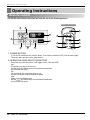
Remote control
The remote control and control panel will look like one of the following pictures.
Power
Temp
Fan Speed
Timer Mode
Energy
Saver
Auto
Swing
1
4
2
6
7
3
5
REMOTE CONTROLLER
1
7
8
5
4
6
2 3
Operating Instructions
1. POWER BUTTON
To turn the air conditioner ON, push the button. To turn the air conditioner OFF, push the button again.
This button takes priority over any other buttons.
2. OPERATION MODE SELECTION BUTTON
Everytime you push this button, it will toggle COOL, FAN and HEAT.
Cool
Heater runs and heats the room.
Compressor runs and cools the room.
Use the
and FAN buttons to set the desied temperature
and circulation fan speed.
Fan
Fan circulate air but compressor does not run.
Use the FAN button to set the desired fan speed.
Heat
Use the
and FAN buttons to set the desied temperature
and circulation fan speed.
Operating Instructions

Owner’s Manual 17
AUTO RESTART
When power is restored after an electrical power failure, the unit will begin to run at its last setting.
When the air conditioner has been performed its cooling operation and is turned off or set to the fan
position, wait at least 3 minutes before resetting to the cooling operation again.
2Hours 3Hours 4Hours 5Hours
6Hours 7Hours 8Hours 9Hours 10Hours 11Hours 12Hours Cancel)
4. FAN SPEED SELECTOR
Everytime you push this button, it is set as follows. (Hi[ ] Low[ ] Hi[ ]....)
5. ROOM TEMPERATURE SETTING BUTTON
This button can automatically control the temperature of the room. The temperature can be set within a
range of 60°F to 86°F by 1°F.
6. ENERGY SAVER
The fan stops when the compressor stops cooling.
Approximately every 3 munutes the fan will turn on and check the room air to determine if cooling is needed.
7. REMOCON SIGNAL RECEIVER
You will usually use shut-off time while you sleep.
For your sleeping comfort,once timer is set,the temperature setting will raise 2 F after
30min and once again after another 30min.
。
A slight heat odor may come from the unit when first switching to HEAT after the cooling
season is over. This odor, caused by fine dust particles on the heater, will disappear quickly.
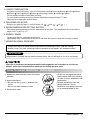
How to insert Batteries (AAA size)
1. Remove the cover from the back of the remote
controller.
2. Insert two batteries.
• Be sure that the (+) and (-) directions are
correct.
• Be sure that both batteries are new.
3. Re-attach the cover.
• Do not use rechargeable batteries.
Such batteries differ from standard
dry cells in shape, dimensions, and
performance.
• Remove the batteries from the
remote controller if the air
conditioner is not going to be used
for an extended length of time.
ENGLISH
3. ON/OFF TIMER BUTTON
Everytime you push this button, timer is set as follows.(1Hour
ENGLISH

18 Room Air Conditioner
Operating Instructions
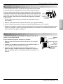
Ventilation
The ventilation lever must be in the CLOSE position in order to maintain the best cooling conditions.
When fresh air is necessary in the room, set the ventilation lever to the OPEN position.
The damper is opened and room air is drawn out.
The direction of air can be controlled wherever you
want to cool by adjusting the horizontal louver and the
vertical louver.
• HORIZONTAL AIR-DIRECTION CONTROL
To control horizontal direction of air flow, set to the
ON position the air-swing switch and the air flow will
be swept horizontally by the automatic air-swing
system.
If you want to stop the air flow from moving, switch off
the air swing switch at the desired position of the
vane.
• VERTICAL AIR-DIRECTION CONTROL
The vertical air direction is adjusted by moving the
horizontal louver.
Part A
Part B
VENTCLOSE OPEN
Before using the ventilation feature,
position the lever, as shown. First, pull down
part to horizontal line with part .
NOTICE
Air Direction

Owner’s Manual 19
ENGLISH
Operating Instructions
How to Attach Drain Pan(Optional)
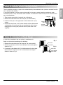
How to Connect a Drain Hose
The air conditioner employs a proper drain method whereby the condensed water (moisture removed from the
air) is drained to the outside.
In very humid weather, (and for reverse cycle models in the reverse mode) excessive condensate water
removed from the air may cause some water to collect. To remove this excess water you can install the drain
pan as detailed below.
1. Take the drain pan which is located in the air discharge.
2. Remove the hole rubber from the base-pan (for some models).
3. Install the drain pan to the right corner of the cabinet with 4 (or 2)
screws.
4. Connect the drain hose of 3/5" inside diameter to the outlet located
at the bottom of the drain pan.You can purchase the drain hose or
tubing locally to satisfy your particular needs. (Drain hose is not
supplied).
A drain hole is provided at the rear of the air conditioner unit.
Select a drain method according to the following.
1. Remove the hole rubber from the base-pan. (for some models)
2. Connect a drain hose of 9/16" inside diameter to the drain pipe as
shown in Fig. 1.
3. Or connect a pipe elbow of 9/16" inside diameter to the drain pipe,
then connect a drain hose of 9/16" inside diameter to the pipe
elbow as shown in Fig. 2.
CABINET
DRAIN
PAN
DRAIN HOSE
SCREW
DRAIN PIPE
DRAIN HOSE
DRAIN PIPE
DRAIN ELBOW
DRAIN HOSE
Fig. 1
Fig. 2

20 Room Air Conditioner
Maintenance and Service
Maintenance and Service
TURN THE AIR CONDITIONER OFF AND REMOVE THE PLUG FROM THE POWER OUTLET.
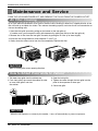
he air filter should be checked at least twice a month to see if cleaning is necessary. Trapped particles in the
filter will build up and block the airflow. This reduces the cooling capacity and also causes an accumulation of
frost on the cooling coils.
1. Open the inlet grille upward by pulling out the bottom of the inlet grille.(a)
In another case, you can open the inlet grille downward by pulling out the top of the inlet grille.(b)
2. Remove the air filter from the front grille assembly by pulling the air filter up or down slightly.
3. Wash the filter using lukewarm water below 40°C (104°F).(c)
4. Gently shake the excess water from the filter completely. Replace the filter.
Mark ∆ of inlet grille means opening direction.
NOTICE
Air Filter Cleaning
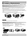
How to Attach Front Grille to Cabinet
1. Pull down front grille from the cabinet top.
2. Push front grille’s tips toward the cabinet in order
to insert front grille’s tabs into
the cabinet.
3. Open the inlet grille.
4. Tighten the screw through the front grille into the
plate of the evaporator or base pan.
5. Close inlet grille.
NOTICE
When the unit operates on extremely hot weather , it turns off automatically to protect compressor.

Owner’s Manual 21
ENGLISH
Maintenance and Service
Common Problems and Solutions
Before calling for service, please review the following list of common problems and solutions.
The air conditioner is operating normally when:
• You hear a pinging noise. This is caused by water being picked up by the condenser on rainy days or in
highly humid conditions. This feature is designed to help remove moisture in the air and improve cooling
efficiency.
• You hear the thermostat click. This is caused by the compressor cycle starting and stopping.
• You see water dripping from the rear of the unit. Water may be collected in the base pan in highly humid
conditions or on rainy days. This water overflows and drips from the rear of the unit.
• You hear the fan running while the compressor is silent. This is a normal operational feature.
The air conditioner may be operating abnormally when:
Problem Possible Causes What To Do
■ The air conditioner is
unplugged or not plugged
in completely
■ The fuse is blown/circuit
breaker is triggered
■ Power failure.
■ The current interrupter
device is tripped.
■ Air flow is restricted
■ TEMP Control set too
higher number.
■ The air filter is dirty.
■ The air conditioner was
just turned on.
■ The room may have been
hot.
■ Cold air is escaping.
■ Cooling coils are iced up
■ The cooling coils are iced
over.
• Make sure the plug is completely plugged into the
outlet
• Check the fuse/circuit breaker box and replace the
fuse or reset the breaker
• In the event of a power failure, set the power control
to OFF. When the power is restored, wait 3 minutes
to restart the air conditioner to prevent the
compressor from overloading
• Press the RESET button located on the power cord
plug. If the RESET button will not stay engaged,
discontinue use of the air conditioner and contact a
qualified service technician.
• Make sure there are no curtains, blinds, furniture or
other obstacles in front of the air conditioner
• Set the TEMP control to a lower number.
• Clean the filter at least every 2 weeks. Refer to the
“Maintenance and Service” section of the manual.
• After the air conditioner is turned on, you need to
give the air conditioner some time to cool the room.
• When the air conditioner is first turned on
you need to allow time for the room to cool down.
• Check for open furnace floor resisters and cold air
returns.
• CLOSE the air conditioner vent
• See Ice appears on the air conditioner below
• Ice may block the air flow and obstruct the air
conditioner from properly cooling the room.
• Set the mode control at HIGH fan or high cool with
the high temperature.
The air conditioner
does not operate
at all
Air conditioner
does not cool
Ice appears on the
air conditioner.

22 Aire Acondicionador
Manual del usuario del acondicionador de aire tipo Ventana
TABLA DE CONTENIDOS
PARA SUS ARCHIVOS
Escriba aquí el modelo y número de serie:
Modelo n°:
Serie n°:
Puede encontrar estos datos en la etiqueta situada en el
lateral de cada unidad.
Nombre del distribuidor:
Fecha de compra:
■ Adjunte su recibo a esta página con la grapadora para
el momento que lo necesite para probar la fecha de su
adquisición o para la validación de la garantía.
LEA ESTE MANUAL
En su interior encontrará muchos consejos útiles sobre la
utilización y mantenimiento de su acondicionador de aire.
Unos pocos cuidados por su parte le pueden ahorrar
mucho tiempo y dinero durante la vida de su
acondicionador de aire.
En la tabla de consejos para la solución rápida de
problemas encontrará muchas respuestas a los problemas
más habituales. Si revisa primero nuestra Tabla de
Consejos para la solución rápida de problemas, tal vez no
necesite llamar nunca al servicio técnico.
PRECAUCIÓN
• Póngase en contacto con un técnico del servicio
autorizado para realizar la reparación y
mantenimiento de esta unidad.
• Póngase en contacto con un instalador para realizar
la instalación de esta unidad.
• Cuando se va a cambiar el cable eléctrico, el trabajo
de reemplazamiento debe ser realizado únicamente
por personal autorizado, utilizando las piezas de
cambio genuinas únicamente.
• El trabajo de reemplazamiento debe ser realizado de
acuerdo con el Código Eléctrico Nacional
únicamente por personal autorizado.
Precauciones de Seguridad.........23
Antes de poner el equipo en
funcionamiento..............................27
Introducción...................................28
Seguraida Electrica.......................29
Instalacion......................................31
Instruccionnes de
Funcionamiento.............................36
Cuidado y Mantenimiento ............40


Antes de poner el equipo en funcionamiento
Manual del Propietario 27
ESPAÑOL
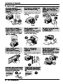
Antes de poner el equipo en funcionamiento
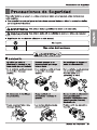
1. Póngase en contacto con un especialista para realizar la instalación.
2. Enchufe correctamente la toma de alimentación.
3. Utilice un circuito dedicado.
4. No utilice un cable alargador.
5. No inicie/cese el funcionamiento enchufando/desenchufando el cable
eléctrico.
6. Si el cable/enchufe está dañado, sustitúyalo solo por una pieza autorizada.
1. Estando expuesto a la circulación directa de aire durante un extenso período
de tiempo podría resultar peligroso para su salud. No exponga a las personas,
animales domésticos, o a las plantas a la circulación de aire durante largos
períodos de tiempo.
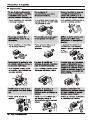
2. Debido a la probabilidad de falta de oxígeno, ventile el cuarto cuando esté
utilizado el aparato junto con estufas u otros aparatos de calefacción.
3. No utilice este aire acondicionado con propósitos especiales no especificados
(Ej.: conservación de dispositivos de precisión, comida, animales domésticos,
plantas y objetos de arte). Tal uso podría dañar los artículos.
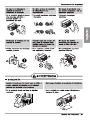
1. No toque las piezas metálicas de la unidad al retirar el filtro. Manejar aristas
afiladas de metal puede causar lesiones.
2. No utilice el agua para limpiar el interior del aire acondicionado. La exposición
al agua puede destruir el aislamiento, conduciendo a posibles descargas
eléctricas.
3. Al limpiar la unidad, asegúrese antes de que la electricidad y el interruptor
están apagados. El ventilador rota a muy alta velocidad durante el
funcionamiento del equipo. Existe la posibilidad de lesiones si acciona
accidentalmente la electricidad de la unidad mientras limpia el interior de la
unidad.
Para cuestiones de reparación y mantenimiento, póngase en contacto con su
distribuidor de servicio autorizado.
Preparación para el funcionamiento
Uso
Limpieza y mantenimiento
Servicio

28 Aire Acondicionador
Introducción
Este símbolo lo advierte de un peligro de accidente por
corriente eléctrica.
Este símbolo lo adiverte de un peligro que pueda causar un
daño del ventliador.
Este símbolo significa condicciones especiales.
CONSEJO
Introducción
Símbolos Utilizados en Este Manual
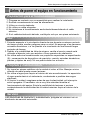
Características
Este aparato debería instalarse de acuerdo con las normas del Código Eléctrico Nacional.
Calentador Eléctrico
Evaporador
Panel de control
Abrazadera
Deflector de aire vertical
(Rejilla horizontal)
Deflector de aire horizontal
(Rejilla vertical)
Descarga de aire
Gabinete
Rejilla frontal
Filtro de aire
Control remoto
Condensador
Plator de base
Compresor
Cable de alimentacion
Entrada de aire
(Rejilla para entrada)

Seguraida Electrica
Manual del Propietario 29
ESPAÑOL
Seguraida Electrica
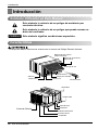
Datos Electricos
115V~ 230V~
El cable de alimentación puede incluir un
dispositivo interruptor de corriente. La
carcasa del enchufe cuenta con un botón de
prueba y otro de reinicio. El dispositivo debe
comprobarse periódicamente presionando
primero el botón TEST y después RESET.
Si el botón TEST no se desconecta o si el
botón RESET no permanece activo,
suspenda el uso del aire acondicionado y
póngase en contacto con un técnico de
servicio cualificado.
Utilice el enchufe de la pared Consumo de Energía
Standard 125V, enchufe de 3
Líneas de 15A, 125V AC
Standard 250V, enchufe de 3
Líneas de 15A, 250V AC
Standard 250V, enchufe de 3
Líneas de 20A, 250V AC
Utilice un fusible de
15AMP. o un
Interruptor de 15AMP.
Utilice un fusible de
20AMP. o un
Interruptor de 20AMP.
No presione nunca el botón de prueba durante el
funcionamiento, de lo contrario el enchufe podría
resultar dañado.
Este dispositivo contiene productos químicos,
incluyendo plomo, conocido en el estado de
California como producto cancerígeno y causante de
defectos de nacimiento y otros daños al sistema
reproductor.
Lávese bien las manos tras manipular el dispositivo.
No desmonte, modifique ni sumerja en agua este
enchufe.
Si el dispositivo se activara, deberá corregir la causa
antes de volver a utilizarlo.
Los hilos conductores dentro del cable están rodeados
por blindajes, que supervisan la corriente de fuga.
Estos blindajes no están puestos a tierra.
Examine periódicamente el cable en busca de
cualquier daño. No utilice este producto si los blindajes
resultaran expuestos.
Evite el riesgo de descargas eléctricas; esta unidad no
puede ser reparada por el usuario por ser resistente y
a prueba de alteraciones. Manipular la porción sellada
de la unidad anulará todas las garantías y quejas de
rendimiento. Esta unidad no está diseñada para su uso
como un interruptor de encendido-apagado.
La forma puede ser diferente según su modelo.
CONSEJO
NO USE CABLE DE EXTENSIÓN EN UNIDADES
DE 208, 230, AND 208/230 VOLTIOS.
Todo el cableado deberá realizarse de acuerdo
con los códigos y reglamentos eléctricos
locales.
El cableado doméstico de aluminio podría
ocasionar problemas especiales. Consulte a un
electricista calificado.
CONSEJO

Manual del Propietario 31
ESPAÑOL
Instalacion
Instalacion
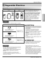
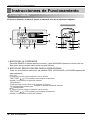
Elija el major lugar
Cómo usar la rejilla de entrada reversible(Para algunos modelos)
APROXIMADAMENTE /
ARRIBA DE 20"
RADIACION
DE CALOR
BARDA
TOLDO
FOAM
AIR
ENFRIADO
30-60"
Nivel
1/4 Ampolla
1
2
(b)
b
(a) (c)
1. Para evitar vibración y ruido, asefúrese de que la unidad esté instalada de manera segura y firmemente.
2. Instale la unidad en lugares fuera de luzsolar directa directamente sobre la unidad.
3. El exterior del gabinete deberá extenderse hacia afuera cuando menos 10" y no deben existir obstáculos,
tales como una barda o pared, dentro de una distancia de 20" desde la pparte posterior del gabinete
porque esto evitará la radiación de calor del condensador.
La restricción del aire exterior reducirá en gran manera la eficiencia de enfriamiento del aire
acondicionado.
4. Para prevenir la reducción de la eficiencia del funcionamiento, instale la unidad para que las rejillas del
cabinete no sean bloqueados.
5. Instale la unidad un poco oblicuamente hacia afuera para no dejar escapar el agua condensado a la
habitación (aproximadamente 1/2" o 1/4 ampolla con nivel).
6. Llene la espuma entre el tope de la unidad y la pared para prevenir que el aire e insectos entren en la
habitación.
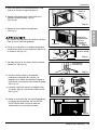
A. Antes de Instalar la rejilla frontal en el cabinete, si usted desea sacar el filtro por arriba;
1. Abra la rejilla de entrada ligeramente (a).
2. Vuelte la rejilla frontal (a).
3. Separe la parte engoznada insertando la punta del destornillador de tipo "–" para desensamblar la rejilla
de entrada desde la rejilla frontal. (b).
4. Luego, gire la rejilla de entrada 180 grados e inserte los ganchos en los huecos inferiores del rijilla frontal.
5. Inserte el filtro e instale la rejilla frontal al cabinete.
B. Si usted desea sacar el filtro por abajo;
La rejilla es ya diseñada para tal manera.
La rejilla es diseñada para limpiar el filtro tanto hacia arriba como hacia abajo.

30 Aire Acondicionador
Seguraida Electrica
IMPORTANTE
(FAVORLEA CON ATENCIÓN)
POR LA SEGURIDAD PERSONAL DEL USUARIO, ESTE
APARATO DEBE SER DEBÍDAMENTE NEUTRALIZADO.
El cordón de energía de éste aparato esta equipado
con tres patas(cable a tierra). Utilice éste con un
enchufe de pared de tres salidas(a tierra) para
minimizar el peligro de choque eléctrico. El cliente
debe revisar el receptor de pared y el circuito por un
electricista calificado para asegurarse que la
recepción esta debidamente neutralizada.
NO CORTE O REMUEVA LA TERCERA PATA(GROUND)
DEL ENCHUFE.
A. SITUACIONES EN LAS CUALES EL APARATO
ES DESCONECTADO OCASIONALMENTE:
Debido al peligro potencial, nosotros no
recomendamos el uso de adaptadores. Sin embargo,
si usted desea utilizar un adaptador, una CONEXIÓN
TEMPORAL, puede ser
efectuada. Utilice adaptadores UL, disponibles en la
mayoría de los estable cimientos de
herramientas. La pata mas grande del adaptador
debe ser alineada con la pata mas grande del
interruptor para asegurarse una polarización
adecuada.
Adaptar la terminal del ground del adaptador a
la cubierta de la pared con un
tornillo no neutraliza el aparato a menos que la
cubierta del tornillo sea de metal, u no sea
insolada, y el receptor de pared este
neutralizado a través del alambrado del la casa.
El cliente debe hacer verificar el circuito por un
electricista calificado para asegurarse que el
receptor esta debidamente neutralizado.
Desconecte el cordón de energía del adaptador,
utilizado una mano en cada uno. De lo contrario, la
terminal del adaptador puede romperse. NO UTILICE el
aparato con un enchufe roto.
B. SITUACIONES EN LAS CUALES EL APARATO
ES DESCONECTADO CON
FRECUENCIA.
No utilice un adaptador en estas circunstancias.
Desconectar el cordón de energía con frecuencia lo
llevará al eventual rompimiento de la terminal de
neutralización. La saluda de energía de la pared
debe ser reemplazada por una salida de tres
patas(neutralizada).
USO DE EXTENSIONES
Debido al peligro potencial, no recomendamos la
utilización de extensiones. Sin embargo, si usted
desea utilizar una extensión, utilice una
certificada por CSA/UL de tres alambres,
catalogada 20A, 250V.
Seguraida Electrica


Manual del Propietario 33
ESPAÑOL
Instalacion
Requisitos de las herramientas sugeridas
DESARMADOR ( , ), REGLA, CUCHILLO, MARTILO, LAPIZ, NIVEL
PREPARACION DEL CHASIS
1. Retire los 4 tornillos que unen el gabinete a la
parte posterior y lateral de la unidad.
2. Deslice la unidad fuera del gabiete tomando la
manija de la charola de la base y jale hacia
adelante miéntras sostiene el gabinete.
3. Corte el sellode chasis de la ventana a la
longitud apropiada. Pele el resfuerzo y aplique la
Cinta de Espuma a la parte inferior del chais de
la ventana.
4.
5.
6.
Inserta la guía marco en la parte inferior del
gabinete.
Inserte los paneles guías en la barra de
retencion superior y en la guia marco del aire
acondicionado.
Sujete las cortinas de la unidad con tornillos
(Tipo A).
BARRA DE RETENCION
SUPERIOR
Cinta de Espuma
TORNILLO
(TIPO A)
TORNILLO
(TIPO A)
GUÍA MACRO
Fig. 1
Fig. 2
Fig. 3
Fig. 4

34 Aire Acondicionador
Instalacion
Instalacion del Gabinete
1. Abra la ventana. Marque una línea en el centro
de la repisa de la ventana entre las molduras de
tope de la ventana lateral.
Coloque sin apretar la ménsula del alféizar en la
ménsula de soporte utilizando el pemo y la
tuerca de segutidad.
2. Coloque la ménsula del alféizar en el alféizar de
la ventana utilizando los tornillos (Tipo B). Apriete
el perno y la tuerca de seguridad.
Repisa de la ventana y alinee la marca central en
el frente del fondo con la línea central marcada
en la repisa de la ventana.
3. Utilizando el tornillo M y la tuerca de seguridad,
coloque la ménsula de soporte en el orificio de la
guía del gabinete. Use el primer orificio de la guía
después de la ménsula del alfézar en el borde
exterior del alféizar de la ventana.
Apriete el perno y la tuerca de seguridad.
Asegúrese de que el gabinete esté inclinado
hacia afuera.
No perfore la charola del fondo. La unidad está
diseñada para operar con aproximadamente 1/2"
de agua en la charola del fondo.
1. No hale el marco de la ventana hacia abajo tan
apretado que se restrinja el movimiento de los
deslizadores. Sujete el gabinete a la repisa de
la ventana insstalando los tornillos (tipo A o B)
a través del gabinete en la repisa de la ventana.
2. El gabinete deberá ser instalado ligeramente
inclinado hacia abajo hacia el exterior.
CONSEJO
MENSULA
DE SOPORTE
TUERCA DE
SEGURIDA
MENSULA DEL
ALFEIZAR
BULÓN
PARTE FRONTAL INTERIOR
REPISA DE VENTANA
MARCO DE LA
VENTANA
BARRA DE
RETENCION SUPERIOR
GABINETE
PANEL
GUIA
CINTA DE
ESPUMA
CINTA DE
ESPUMA
TORNILLO(TIPO B)
Parte Frontal Interior
ORIFICIO DE
CARRIL DE GABINETE
MENSULA
DE SOPORTE
TORNILLO PARA
METALES
(TIPO D)
Y
TUERCA DE SEGURIDA
BORDE EXTERIOR
DEL ANTEPECHO
DE LA VENTANA
TORNILLO(TIPO B)
MENSULA
DEL ALFEIZAR
BARRA
DE
RETENCION
SUPERIOR
Fig. 5
Fig. 6
Fig. 7
Fig. 8
Fig. 9

Manual del Propietario 35
ESPAÑOL
Instalacion
5.
Hale cada panel guía completamente a cada
lado de la ventana y repita del paso 2.
6.
Adjunte cada panel guí
a a cada lado de la
ventana usando tornillos (Tipo C).
(Ver Fig.10)
7.
Deslice el chasís dentro del gabinete.
(Ver Fig.11)
Por razones de seguridad, re instale los tornillos
(Tipo A) en los lados del gabinete.
8.
Corte la tira de goma a la medida apropiada e
introdúzcala entre la parte superior e inferior de
la ventana. (Ver Fig. 12)
9.
Se debe instalar el asa antes de fijar el frente
decorativo. (Ver Fig. 13)
10.
Instale la rejilla frontal en el cabinete
insertando la lengüeta en la rejilla a la
lengüeta en el frente del cabinete. Empuje la
rejilla hasta que se cierre con sonido de golpe.
(Ver Fig. 14)
Levante la rejilla de entrada y asegúrela con
un tornillo (tipo A) a través de la rejilla frontal.
(Ver Fig.14)
Ahora la instalación del aire acondicionado en
la ventana es completada. Vea los DATOS
ELECTRICOS para instalar el cable de
alimentación en la toma de corriente.
CORDÓN DE
ALIMENTACIÓN
ELÉTRICA
TORNILLO
(TIPO A)
TORNILLO
SOPORTE DE
CERRADURA
TIRA DE GOMA
TORNILLO
(TIPO C)
Fig. 10
Fig. 11
Fig. 12
Fig. 13
Fig. 14
Fig. 15
3.
4.

36 Aire Acondicionador
Control remoto
El mando a distancia y el panel de control se parecerán a los de las siguientes imágenes.
Power
Temp
Fan Speed
Timer Mode
Energy
Saver
Auto
Swing
1
4
2
67
3
5
CONTROL REMOTO
1
7
8
5
4
6
2 3
Instruccionnes de Funcionamiento
1. BOTÓN DE LA CORRIENTE
Para ENCENDER el sistema presione el botón, y para APAGARLO presione el botón otra vez.
Este botón tiene prioridad sobre todos los otros botones.
2. BOTÓN DE SELECCIÓN DEL MODO OPERACIONAL
Cada vez que presione este botón, las palabras FRÍO, VENTILADOR y CALENTAR aparecerán
alternadamente.
Instruccionnes de Funcionamiento
COOL
(frío)
:
El compresor funciona y enfría la habitación. Use los
botones
deseada y la velocidad
de circulación del ventilador.
TEMP/TIMER y FAN (ventilador)
para configurar la temperatura
FAN
(ventilador)
Utilice el botón FAN (ventilador) para
configurar la velocidad deseada del ventilador.
no funciona.El ventilador hace circular el aire pero el compresor
HEAT
(
CALENTAR):
El calentar funciona y calentar la habitación. Use los
botones
deseada y la velocidad
de circulación del ventilador.
TEMP/TIMER y FAN (ventilador)
para configurar la temperatura

Manual del Propietario 37
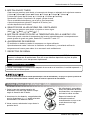
Cómo Poner Las Baterias (AAA)
1. Quite la tapa de la parte posterior del
telemando. Para ello haga deslizar la tapa
según la dirección del la flecha.
2. Introduzca las dos baterías, asegurándose de
que las direcciones (+) y (-) estén colocadas
correctament. Use baterías nuevas.
3. Volver a cerrar, resbalando la tapa hasta la
posición inicial.
• No utilice baterís recargables,
éstas son diferentes de forma,
de dimensión y uso respecto a
las baterías secas usuales.
• Seque las baterías del
telemando cuando el
acondicionador no vaya a ser
usado durante un largo
período.
REINICIO AUTOMÁTICO
Cuando se restablezca la alimentación después de un corte en el suministro, la unidad empezará a
funcionar con su último ajuste.
Cuando el aire acondicionado ha estado operando bajo la fase de enfriamiento y se apaga o se ajusta la posicion de
ventilacion, espere por lo menos 3 minutos, antes de reiniciar la operación de enfriamiento.
(63$嘰2/
Instruccionnes de Funcionamiento
3. BOTÓN ON/OFF TIMER
Cada vez que presione este botón, el marcador de tiempo se ajustará de la siguiente manera:
(1Hora 2Horas 3Horas 4Horas 5Horas 6Horas 7Horas
8Horas 9Horas 10 Horas 11 Horas 12 Horas Cancelar).
4. SELECTOR DE LA VELOCIDAD DEL VENTILADOR
Cada vez que presione este botón, el ajuste es como sigue.
(Alto[ ] Bajo[ ] Alto[ ]...)
5. BOTÓN DE SELECCIÓN DE LA TEMPERATURA DE LA HABITACI ÓN
Este botón puede controlar la temperatura del cuarto automáticamente. La temperatura se
puede ajustar de grado en grado, desde 60ÛF hasta 86ÛF cada 1ÛF.
6. AHORRADOR DE ENERGÍA
El ventilador se detiene cuando el compressor no sigue enfriando.
Aproximadamente cada 3 minutos el ventilador se encenderá, y necesitará verificar la
temperatura del cuarto para saber si es necesario más enfriamiento.
7. RECEPTOR DE SEÑAL
Normalmente utilizará el temporizador de apagado mientras duerme.
Para su comodidad mientras duerme, una vez que se
el ajuste de temperatu se
elevará 2°F después de 30 minutos y una
después de otros 30 minutos.
fija el temporizado ,
vez más
ra
Un leve olor podría despedirse de la unidad la primera vez que enciende HEAT (Calentar) al
terminal la temporada de enfriamiento. Ese olor es por haberse depositado un poco de polvo
sobre el calentador y va a desaparecer rápidamente.

38 Aire Acondicionador
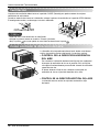
Instruccionnes de Funcionamiento
La palanca de ventilación deberá estar en la posición CLOSE (Cerrado) para poder mantener las mejores
condiciones de enfriamiento.
Cuando se necesite aire fresco en la habitación, coloque la palanca de ventilación en la posición OPEN (Abierto).
El amortiguador se abre y se descarga el aire de la habitación.
Antes de usar la característica de ventilación,
coloque la palanca como se muestra. Primero jale hacia
abajo la parte para que quede en una línea horizontal con la parte .
CONSEJO
Ventilacion
Part A
Part B
VENTCLOSE OPEN
VENTILACION
CERRAR ABRIR
Como controlar la direccion del aire
La dirección del aire puede controlarse hacia donde usted desee
enfriar ajustando la persiana horizontal y la persiana vertical.
• CONTROL DE LA DIRECCION HORIZONTAL
DEL AIRE
Para controlar la dirección horizontal del flujo del aire, coloque el
interruptor de oscilación de aire en la posición ON y el flujo de
aire soplará horizontalmente por medio del sistema de oscilación
automática de aire.
Si desea detener el flujo de aire, coloque el interruptor de
oscilación de aire en la posición deseada de la aleta.
• CONTROL DE LA DIRECCIÓN VERTICAL DEL AIRE
La dirección de aire vertical es ajustada moviendo la rejila
horizontal.

Manual del Propietario 39
ESPAÑOL
Instruccionnes de Funcionamiento
Como colocar la charola de purga(Opcional)
Como conectar una manguera de purga
El aire acondicionado utiliza un método de purga adecuado en donde
el agua condensada (humedad retirada del aire) se purga al exterior.
En climas demasiado húmedos (y para modelos de ciclo invertido en la
modalidad de inversión) el agua condensada excesiva que se retira del
aire puede ocasionar que se recolecte algo de agua. Para eliminar este
exceso de agua, puede instalar una charola de purga como se detalla
a continuación.
1. Tome la charola de purga que se localiza en la descarga de aire o
en la barrera.
2. Retire el orificio de hule de la charola de la base. (para algunos modelos).
3. Instale la charola de purga en el extermo izquierdo del gabinete con 4 (o 2) tornillos.
4. Conecte la manguera de purga en la descarga localizada en el fondo de la charola de purga. Puede
adquirir la manguera o tubería de purgga localmente para satisfacer sus necesidades particulares
(No se incluye la manguera de purga).
Existe una manguera de purga inclulda en la parte de atràs de la
unidad de aire acondicionado.
Elija un método de purga de acuerdo a lo siguiente.
1. Retire el orificio de hule de la charola de la base. (para algunos
modelos).
2. Conecte una manguera de purga de 9/16" de diámetro interior al
tubo de purga como se muestra en la Figura 1.
3. Conecte un codo de tubo de 9/16" de diàmetro interior a la
tubería de purga, después conecte una manguera de purga de
9/16" de diàmetro interior al codo de tubo como se muestra en la
Figura 2.
CABINETE
CHAROLA
DE PURGA
MANGUERA
DE PURGA
TORNILLO
TUBO DE PURGA
MANGUERA DE PURGA
TUBO DE PURGA
CODO DE PURGA
MANGUERA
DE PURGA
Figura 1
Figura 2

40 Aire Acondicionador
Cuidado y Mantenimiento
Limpleza del filtro de aire
Como instalar la parrilla delantera en el gabinete
El filtro de aire deverá revisarse cuando menos dos veces al mes para vertioficar si es necesario
limpiarlo. Las partículas atrapadas en el filtro podrían acumularse y bloquear el flujo de aire. Esto
reduce la capacidad de enfriamiento y también ocasiona la acumulación de escarcha en los
serpentines de enfriamiento.
1. Abra la rejilla hacia arriba tirando la parte inferior de la rejilla de entrada (a). En otro caso, usted
puede abrir la rejilla de entrada hacia abajo tirando la parte superior de la rejilla de entrada.(b)
2. Retire el filtro de aire del ensamblaje de la parrilla delantera jalando el filtro de aire ligeramente hacia
arriba.
3. Lave el filtro de aire usando agua tibia a menos de 40°C (104°F).
4. Sacuda suavemente el exceso de agua del filtro completamente. Vuelva a colocar el filtro.
La marca ∆ de la rejilla de entrada significa la dirección abierta.
CONSEJO
Cuidado y Mantenimiento
APAGUE EL AIRE ACONDICIONADO Y SAQUE EL ENCHUFE DEL TOMA CORRIENTE DE LA PARED.
1. Jale hacia abajo la parrilla delantera desde la
parte superior del gabinete.
2. Oprima las puntas de la parrilla delantera hacia
el gabinete para insertar las lengüetas de la
parrilla delantera en el gabinete.
3. Abra la parrilla de admisión.
4. Apriete el tornillo a través de la parrilla
delantera dentro en la placa de evaporador o
base cacerola.
5. Cierre la parrilla de admisión.
CONSEJO
Cuando la unidad opera en clima extremadamente caliente,se apaga automáticamente para proteger
el compresor.

Manual del Propietario 41
ESPAÑOL
Cuidado y Mantenimiento
Problemas y soluciones habituales
Antes de llamar al servicio, tenga a bien revisar la siguiente lista de problemas y sus soluciones.
El acondicionador de aire está funcionando normalmente cuando:
• Escucha un sonido metálico. Lo causa el agua que recoge el condensador en días lluviosos o en condiciones de
mucha humedad. Esta característica está diseñada para ayudar a quitar la humedad en el aire y mejorar la
capacidad de enfriamiento.
• Oye un clic en el termostato. Lo causa el ciclo del compresor que comienza y se detiene.
• Ve gotear agua de la parte posterior de la unidad. El agua puede ser recogida en la bandeja de base en
condiciones de mucha humedad o días de lluvia. Esta agua desborda y gotea desde la parte posterior de la unidad.
• Oye funcionar el ventilador mientras el compresor está silencioso. Esto es una característica operativa normal.
Problema Causas posibles Qué hacer
■ El acondicionador de aire está
desenchufado o no bien
enchufado
■ El fusible está fundido / el
disyuntor está interrumpido
■ Corte de corriente
■ El dispositivo interruptor de
corriente está desconectado.
■ El flujo de aire está disminuido
■ Coloque el control de
TEMPERATURA en un número
más alto.
■ El filtro de aire está sucio.
■ El acondicionador de aire se
acaba de encender.
■
El cuarto aún está caliente.
■ El aire frío se escapa.
■ Los serpentines de
enfriamiento están congelados
■ Los serpentines de
enfriamiento están cubiertos de
hielo.
• Asegúrese que el enchufe está completamente
enchufado dentro del tomacorriente
• Compruebe el fusible /la caja del disyuntor y reemplace
el fusible o vuelva el disyuntor a su lugar.
• En el caso de un corte de corriente, coloque el control
de encendido en OFF. Cuando se haya restaurado la
corriente, espere durante 3 minutos para volver a hacer
funcionar el acondicionador de aire para prevenir la
sobrecarga del compresor.
• Presione el botón RESET situado en el enchufe del
cable de alimentación. Si el botón RESET no
permanece activo, suspenda el uso del aire
acondicionado y póngase en contacto con un técnico de
servicio cualificado.
• Asegúrese que no haya cortinas, persianas, muebles u
otros obstáculos frente al acondicionador de aire
• Gire el control de TEMPERATURA a un número más
bajo.
• Limpie el filtro al menos una vez cada dos semanas.
Refierase a la sección “Cuidado y Mantenimiento” del
manual.
• Después que se enciende el acondicionador de aire,
debe darle un tiempo al acondicionador de aire para
enfriar la habitación.
• Cuando usted enciende el aire acondicionado debe
esperar un momento para que la habitación se enfrie.
• Busque alguna hornalla de resistencia encendida y el
aire frío vuelve.
• CIERRE la ventilación del acondicionador de aire
• Vea Aparece hielo sobre el acondicionador de aire abajo
• El hielo puede bloquear la corriente de aire e impedir
que el acondicionador de aire enfríe correctamente la
habitación.
• Ajustar el control de modo en ‘Ventilación alta’ o
‘Erfriamiento alto’ con la temperatura alta.
El acondicionador
de aire no
funciona para
nada
El acondicionador
de aire no enfría
Aparece hielo
sobre el
acondicionador
de airea


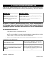
WARRANTY PERIOD:
HOW SERVICE IS HANDLED:
The warranted labor covers the cost of In-Home Service on all
parts including the compressor.
THIS LIMITED WARRANTY DOES NOT APPLY TO:
CUSTOMER INTER-ACTIVE CENTER NUMBERS:
To Prove Warranty Coverage
To Obtain Nearest Authorized Service Center or Sales
Dealer, or to Obtain Product, Customer, or Service
Assistance
LG ROOM AIR CONDITIONER LIMITED WARRANTY
-
USA
Labor: 5 Year from the Date of Purchase.
Parts: 5 Year from the Date of Purchase.
Compressor: 5 Years from the Date of
Purchase.
LG Electronics Inc. will repair or at its option replace, without charge, your product if it proves to be defective in
material or workmanship under normal use during the warranty period set forth below, effective from the date of
original consumer purchase of the product. This limited warranty is good only to the original purchaser of the product
and effective only when used in the United States including Alaska, Hawaii, and U.S. Territories.
1. Service trips to your home to deliver, pick up, and/or install the product, instruct, or replace house fuses or
correct wiring, or correction of unauthorized repairs; and
2. Damages or operating problems that result from misuse, abuse, operation outside environmental
specifications or contrary to the requirements or precautions in the Operating Guide, accident, vermin,
fire, flood, improper installation, acts of God, unauthorized modification or alteration, incorrect electrical
current or voltage, or commercial use, or use for other than intended purpose.
3. Therefore, the cost of repair or replacement of such a defective product shall be borne by the consumer.
Retain your Sales Receipt to prove date of purchase.
A copy of your Sales Receipt must be submitted at
the time warranty service is provided.
Call 1-800-243-0000, 24 hrs a day, 7 days per week.
Choose the appropriate prompt from the menu, and
have your product type (Room Air Conditioner), model
number, serial number, and ZIP Code; or visit our
website at http://www.lgappliances.com.
Patent No. : Us 6, 412, 298
Printed in China
THIS WARRANTY IS IN LIEU OF ANY OTHER WARRANTIES, EXPRESS OR IMPLIED, INCLUDING WITHOUT LIMITATION, ANY
WARRANTY OF MERCHANTABILITY OR FITNESS FOR A PARTICULAR PURPOSE. TO THE EXTENT ANY IMPLIED WARRANTY IS
REQUIRED BY LAW, IT IS LIMITED IN DURATION TO THE EXPRESS WARRANTY PERIOD ABOVE. LG WILL NOT BE LIABLE FOR
ANY CONSEQUENTIAL, INDIRECT, OR INCIDENTAL DAMAGES OF ANY KIND, INCLUDING LOST REVENUES OR PROFITS, IN
CONNECTION WITH THE PRODUCT. SOME STATES DO NOT ALLOW LIMITATION ON HOW LONG AN IMPLIED WARRANTY
LASTS OR THE EXCLUSION OF INCIDENTAL OR CONSEQUENTIAL DAMAGES, SO THE ABOVE LIMITATIONS OR EXCLUSIONS
MAY NOT APPLY TO YOU.
Call 1-800-243-0000 and choose the appropriate prompt. Please
have product type (Room Air Conditioner), model number, serial
number, and ZIP code ready.

1-800-243-0000
LG Customer Information Center
Register your product Online
www.lgappliances.com
LG ELECTRONICS,INC.
1000 Sylvan Ave.,Englewood Cliffs,NJ 07632
-
 1
1
-
 2
2
-
 3
3
-
 4
4
-
 5
5
-
 6
6
-
 7
7
-
 8
8
-
 9
9
-
 10
10
-
 11
11
-
 12
12
-
 13
13
-
 14
14
-
 15
15
-
 16
16
-
 17
17
-
 18
18
-
 19
19
-
 20
20
-
 21
21
-
 22
22
-
 23
23
-
 24
24
-
 25
25
-
 26
26
-
 27
27
-
 28
28
-
 29
29
-
 30
30
-
 31
31
-
 32
32
-
 33
33
-
 34
34
-
 35
35
-
 36
36
-
 37
37
-
 38
38
-
 39
39
-
 40
40
-
 41
41
-
 42
42
-
 43
43
-
 44
44


LG LW2410HR El manual del propietario
- Tipo
- El manual del propietario
en otros idiomas
- English: LG LW2410HR Owner's manual
Artículos relacionados
-
LG Electronics LWHD7000HR Manual de usuario
-
LG LW2416HR El manual del propietario
-
LG LW1212HR Guía de instalación
-
LG LW1815HR El manual del propietario
-
-
-
-
LG LW8011ER El manual del propietario
-
-
LG M8003R El manual del propietario
Otros documentos
-
Goldstar WG1805R El manual del propietario
-
Panasonic HQ-2243TH Manual de usuario
-
Goldstar WG8005R El manual del propietario
-
-
-
-
Quasar HQ-2244UH Manual de usuario
-
-
-