Kenmore Elite 72180804400 Guía de instalación
- Tipo
- Guía de instalación

Models/Modelos
721.80802
721.80803
721.80804
721.80809
Read and save these
installation instructions.
Lea y guarde estas
instrucciones de
instalaciSn
INSTALLATIONINSTRUCTIONS
INSTRUCCIONESDEINSTALACION
l
E L I T E _rR>
MicrowaveHoodCombination
CombinacibnMicroondasCampana
Part No. 3828W5U0360 Sears, Roebuck and Co., Hoffman Estates, IL.60179 U.S.A www.sears.com.

YOUR SAFETY FIRST
BEFORE YOU START
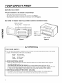
• Proper installation is the installer's responsibility!
- Read the entire manual before you begin.
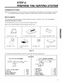
- The model number label is located on the oven front. See Figure 1.
- Mounting plate is located on back side of microwave oven. See Figure 2.
BE SURE TO READ THE FOLLOWING SAFETY INSTRUCTIONS:
Model and Serial
Number Plate
Cooking Guide
±
Mounting
plate
(Remove fron
oven to install.)
Back of oven
Figure 1 Figure 2
WARNING
FOR YOUR SAFETY:
• You will need TWO people to install this oven. It is heavy and could cause personal injury if not handled
properly. The dimensions of the oven are as follows:
Height : 16-7/16 inches
Width : 29-15/16 inches
Depth : 15-3/8 inches
Weight : 62 pounds
• AVOID ELECTRICAL SHOCK!
- Before you drill into the wall, note where electrical outlets are and where electrical wires might be
concealed behind the wall.
YOU COULD GET AN ELECTRIC SHOCK it you contact electrical wires with your drill bit.
- Locate and disconnect the power of any electrical circuits that could be affected by installing this oven.
IF YOU DO NOT DISCONNECT THE POWER, YOU COULD GET AN ELECTRIC SHOCK.
• ELECTRICAL RATING OF THIS OVEN : 120V, 60Hz.
- You need a 120V, 60Hz, AC only, 20A, fused electrical supply (located in the cabinet above the
microwave as close as possible to the microwave circuit) serving only the microwave.

YOUR SAFETY FIRST
• THIS APPLIANCE MUST BE GROUNDED!
- If there is an electrical short circuit, grounding reduces the risk of electrical shock by providing an escape
wire for the electric current. This appliance is equipped with a cord having a grounding wire with a
grounding plug.
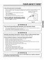
• Place the plug into a properly installed and grounded
outlet. See Figure 3.
• Do not use an extension cord.
• Keep the power cord dry and do net pinch or crush it.
• DO NOT, UNDER ANY CIRCUMSTANCES, REMOVE
THE POWER SUPPLY CORD GROUNDING PRONG!
This appliance MUST be grounded!
PROPERLY POLARIZED AND
GROUNDED OUTLET
Three-Pronged (Grounding) plug
Figure 3
_, WARNING _,
If you use the grounding plug improperly, you risk electric shock!
- Check with a qualified electrician if you are not sure whether the oven is properly grounded or if you do
not completely understand the grounding instructions.
DO NOT USE A FUSE IN THE NEUTRAL OR GROUNDING CIRCUIT.
_k WARNING _k
Improper grounding could result in electric shock or other personal injury.
SAVE THESE INSTRUCTIONS FOR THE LOCAL ELECTRICAL INSPECTOR'S USE.
• DO NOT EXPOSE YOURSELF TO EXCESSIVE MICROWAVE ENERGY!
- DO NOT try to operate the microwave oven with the door open.
- DO NOT tamper with or defeat the safety interlocks.
- DO NOT place objects between the microwave oven front face and the door.
- DO NOT allow soil or cleaner residue to build up on the flat surfaces around the microwave oven door.
- DO NOT operate the microwave oven if it is damaged.
- The microwave oven door must close properly to operate safely.
- DO NOT use the microwave oven:
• If the door is bent.
• If the hinges or latches are broken or loose.
• If the door seals, sealing surfaces or glass is broken.
- DO NOT attempt to adjust or repair the oven yourself!
It should be adjusted and repaired by a qualified technician who can check for microwave leakage after
repairing the oven.
_, WARNING _,
If you do not use the microwave oven as instructed, you could be exposed
to excessive microwave energy.

YOUR SAFETY FIRST
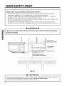
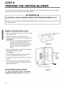
• MAKE SURE YOU HAVE ENOUGH SPACE AND SUPPORT.
- Mount the oven against a flat, vertical wall, so that it is supported by the wall. The wall should be
constructed of minimum 2" x 4" wood studding and 3/8" thick drywall or plaster/lath.
- ATTACH AT LEAST ONE of the two lag screws supporting the oven to a vertical, 2" x 4" wall stud.
- DO NOT mount the microwave oven to an island or peninsula cabinet.
- BE SURE the upper cabinet and rear wall structures are able to support 150 Ibs., plus the weight of any
items you place inside the oven or upper cabinet.
- Locate the oven away from strong draft areas, such as windows, doors, and strong heating vents.
- BE SURE you have enough space. See Figure 4 below for minimum vertical and horizontal clearance.
:Z:
WARNING
If you do not mount the oven as instructed, you risk personal injury and/or
property damage.
30"min.cabinetopeningwidth
30"min.clearancefrombottom
ofcabinettocookingsurface
or countertop
(Use templates included
with installation instructions)
-Grounded Plug
(inside upper cabinet)
Power Supply
Cord Hole
I
Figure 4
CAUTION
• Before you begin installing the oven, PLACE A PIECE OF THE CARTON OR OTHER HEAVY MATERIAL
(a blanket) over the countertop or cooktop to protect it. Do not use a plastic cover.
Failure to protect these surfaces could result inproperty damage.

PARTS, TOOLS, MATERIALS
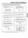
THE FOLLOWING PARTS ARE SUPPLIED WITH THE OVEN:
NOTE: Depending on your ventilation requirements, you may not use all of these parts.
Damper/duct connector
(for roof vented or wall vented installation)
Not Actual Size
One power cord clamp and
One dark-colored mountinc
(to hold the power cord)
Actual Size
screw
One power cord clamp bushing - Actual Size (for the cord hole in a metal upper cabinet)
Four 1/4" x 2" lag screws - Actual Size
(for wall stud holes)
Four 1/4" x 3" toggle bolts - Actual Size
(for drywall holes)
Two 114" x 3" bolts - Actual Size
(for securing to the upper cabinet)
Two tapping screws - Actual Size
(for attaching the damper duct connector)
Four spring toggle heads - Actual Size
(for the toggle belts)
One upper cabinet template - Not Actual
Size
NOTE: You need to install at least one lag screw into a 2" x 4" stud and four anchor bolts into the wall,
and the mounting area must meet the 150 Ibs. weight requirement.

PARTS, TOOLS, MATERIALS
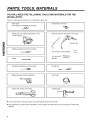
YOU WILL NEED THE FOLLOWING TOOLS AND MATERIALS FOR THE
INSTALLATION:
Carton or other heavy material for covering the counter top.
Clear tape
(for taping the templates to the wall)
Stud finder or thin nail.
Saber saw (for cutting vent holes for roof
or wall venting)
Phillips screwdriver (for the screws)
Pencil
Flat blade screwdriver (for the bolts)
Key hole saw (for the power cord hole)
3/8" and 3/4" wood drill bits ,_
1/2" and 3/16"
drill bits
Plumb line
Duct TapeMeasuring tape (metal preferred)
Small side cutters or tin snips
,,i
Caulking gun
• If you have brick or masonry walls, you need special hardware and tools.
• The ductwork you need for the installation is not included. All wall and roof caps must have a back-draft
damper.

STEP 1: PREPARE THE
ELECTRICAL CONNECTIONS
_k WARNING _k
AVOID ELECTRICAL SHOCK! THIS APPLIANCE MUST BE GROUNDED!
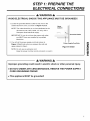
1. Locate the grounded electric outlet for this oven in the
cabinet above the oven, as shown in Figure 4 Detail.
NOTE: The outlet should be on a circuit dedicated to the
microwave oven 120V, 60Hz., AC only, with a
20ampere fused electrical supply.
IMPORTANT: Ifyou do not have the proper wall outlet,
you MUST have one installed by a qualified
electrician.
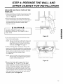
2. You will cut the power-supply-cord hole (shown in
Figure 4 Detail) later when you prepare the wall and
upper cabinet in Step 4.
NOTE: Do not use an extension cord.
Keep the power cord dry and do not pinch or crush it.
Upper I
Cabinet
-Grounded Outlet
Power-Supply-CordHole
Figure 4 Detail
_, WARNING _,
Improper grounding could result in electric shock or other personal injury.
• DO NOT, UNDER ANY CIRCUMSTANCES, REMOVE THE POWER SUPPLY
CORD GROUNDING PRONG!
• This appliance MUST be grounded!

STEP 2:
PREPARE THE VENTING SYSTEM
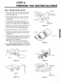
NOTE: The ductwork you need for outside ventilation is not included with your oven. The standard ductwork
fittings and length are shown in Figure 9, page 9.
WARNING - FIRE HAZARD A
I THIS OVEN MUST BE PROPERLY VENTED!
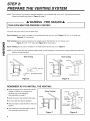
You may vent your oven in one of three ways:
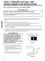
Roof Venting If your oven is located on an outside wall near the roof, as in Figure 6 (3-1/4" x 10" duct) and
Figure 8 (6" round duct.)
Wall Venting If your oven is located on an outside wall on the first floor of your house, as in
Figure 5 (3-1/4" x 10" duct) and Figure 8 (6" round duct.)
Room Venting If your oven is located on an inside wall of your house, as in Figure 7.
NOTE: If you choose the rear exhaust method (roof or wall venting), be sure there is enough clearance within the
wall for the exhaust duct.
I
cabinet
Wall venting
Wall Venting
wall cap
/1
3-1/4"x10" through-the-wall
duct
Figure 5
cabinet_ _
o
Roof ventin_
Roof Venting
_ roof cap
3-1/4"x10"
duct
through-the-roof
Figure 6
REMEMBER AS YOU INSTALL THE VENTING:
• Keep the length of the ductwork and the
number of elbows to a minimum to
ventilate your oven efficiently.
See examples on page 9.
• Keep the size of the ductwork the same.
• Do not install two elbows together.
• Use duct tape to seal all joints in the duct
system.
• Use caulking to seal the exterior wall or
roof opening around the cap.
cabinet
ov_
Room Venting
Figure 7
roof cap
6" min.
diameter
elbow
3-1/4"to round
ducttransition
wall cap
3-1/4"toround
ductworktransition
Figure 8

STEP 2:
PREPARE THE VENTING SYSTEM
STANDARD FITTINGS
NOTE: If the existing duct is round, you must use a rectangular-to-round adapter, with a rectangular 3" extension
duct installed between the damper assembly and the adapter to prevent the exhaust damper sticking.
DUCT LENGTH
The total length of the duct system, including straight duct, elbows, transitions, wall or roof caps must not
exceed the equivalent of 140 feet.
For best performance, do not use more than three 90 degree elbows.
Below are the standard fittings and their equivalent length in feet.
3-1/4"x10" to 6" = 5ft.
3-1/4"x10" roof cap = 24ft.
3-1/4"x10" 90° elbow = 25ft.
90° elbow = 1Oft.
3-1/4"x10" wall cap
= 40ft.
45 °elbow = 5ft. 3-1/4"x10" fiat elbow
= 1Oft.
Figure 9
To calculate the equivalent length of each duct piece used, see the examples below.
For 3-1/4"x10" SYSTEMS
3_1/4"x10" _ 6ft. _ wall cap
90 ° elbow *_fr! I 0_ b"
1 3-1/4" x 10" 90° elbow = 25ft.
1 wall cap = 40 ft.
8 feet straight duct = 8 ft.
TOTAL LENGTH = 73 ft.
Exam )les
For 6" ROUND SYSTEMS
90°elbows _---- 6ft. -_/wall cap
transi_
1 transition = 5 ft.
2 90 °elbows = 20 ft.
1 wall cap = 40 ft.
8 feet straight = 8 ft.
TOTAL LENGTH = 73 ft.

STEP 3:
PREPARE THE VENTING BLOWER
Your microwave oven is shipped with the blower assembled for room venting (recirculating). You need to adjust
the blower if you want wall vented or roof vented installation.
WARNING A
ELECTRICAL SHOCK HAZARD! UNPLUG UNIT BEFORE WORKING ON IT.
• DO NOT PULL OR STRETCH THE BLOWER WIRING! Pulling and stretching the blower wiring could result
in electrical shock.
REMOVE THE MOUNTING PLATE:
1. Remove any shipping materials and parts from inside
the microwave oven.
2. Cover the counter top or cooktop with a thick,
protective covering to protect it from damage and dirt.
See Figure 10.
NOTE: If you have a free-standing range, disconnect
it, move it onto a piece of cardboard or
hardboard and pull it away from the wall, so
that you can get closer to the upper cabinet
and back wall for easier measuring and
drilling.
3. Remove mounting plate 2 screws from the mounting
plate as shown and discard them.
(See Figure 11.)
4. The mounting plate will also be used to locate and
mark the mounting holes on the rear wall.
5. Locate exhaust adaptor, grease filters and hardware
packet.
6. At this point, remove any adhesive tape (if there is
any), on the exhaust adaptor, the grease filters and
the power supply cord.
ROOM VENTED INSTALLATION:
Go to STEP 4, PREPARE THE WALL AND UPPER
CABINET FOR INSTALLATION located on page 13.
A thicK, protective
covenllg
Figure 10
I il II:il pM°t_enting
_--- Control panel side
Figure 11
10

STEP 3:
PREPARE THE VENTING BLOWER
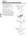
WALL VENTED INSTALLATION:
1. Remove two blower unit mounting screws and one
blower plate screw. Remove the blower plate from
cabinet. See Figure 12.
2. Carefully lift the blower unit out of the microwave
oven. Disconnect the blower wire from connector.
See Figure 13.
3. Use side cutters or tin snips to cut and remove
knockouts "B" from Back plate. Discard knockouts.
Be careful not to distort the plate. See Figure 14.
4. Rotate the unit so that the exhaust ports face the rear
of the cabinet. See Figure 15. Before you insert
blower unit, blower wire must be like Figure 15.
5. Reassemble the blower wire into the connector.
6. Place blower unit back into cabinet. Check that the
exhaust ports face towards the rear of the cabinet.
See Figure 16.
7. Reattach the blower plate to the top of the cabinet as
it was originally assembled. Attach with one blower
unit mounting screw and then one blower plate
mounting screw. See Figure 17.
NOTE: When using wall venting,you need one
blower unit mounting screw.See Figure 17.
8. Go to STEP 4, PREPARE THE WALL AND UPPER
CABINET FOR INSTALLATION located on page 13.
blower unit
Knockouts "B"
connector
/
blower plate
back plate
_late
mounting screw
blower unit
mounting screw
Figure 12
blower wire
Figure 13
=
Parts "B"
Knockouts Parts "B"
Figure 14
exhaust
ports
Figure 16
blower
unit
Figure 15
_ lower plate
mounting
screw
blower unit _
exhaust
blower unit
mounting screw
Figure 17
11

STEP 3:
PREPARE THE VENTING BLOWER
ROOF VENTED INSTALLATION:
1.
2.
3.
4.
5.
6.
Remove two blower unit mounting screws and one
blower plate screw. Remove the blower plate from
cabinet. See Figure 18.
Carefully lift the blower unit out of the microwave
oven.
Rotate blower unit 90 ° so the exhaust ports face the
top of the cabinet. See Figure 19.
Place blower unit back into microwave oven.
Use side cutters or tin snips to cut and remove
knockouts "A" from blower plate. Discard knockouts.
Be careful not to distort the plate. See Figure 20.
Reattach blower plate to microwave oven. Attach with
the one blower unit mounting screw and then the one
blower plate mounting screw. See Figure 21.
NOTE: When using Roof venting,you need one
blower unit mounting screw.See Figure 21.
_ lower plate
mounting
screw
blower plate
blower unit
mounting screw
Figure 18
blower
unit
Figure 19
Knockouts "A"
blower plate
Figure 20
blower unit
blower plate
mounting
screw
blower unit
mounting screw
Figure 21
12

STEP 4: PREPARE THE WALL AND
UPPER CABINET FOR INSTALLATION
MEASURE AND TACK / TAPE UP THE
TEMPLATE
1. Using a plumb line and (metal) measuring tape, find
and mark the vertical center line (_on the back
wall, as in Figure 22.
2. Find and mark one or two points where the studs
are on the wall (Studs are normally 16 inches apart.)
and then measure and mark the stud locations. If
you cannot find any wall stud, consult a local
building contractor.
A CAUTION A
DO NOT ATTEMPT TO INSTALL THE
MICROWAVE OVEN IF YOU CANNOT FIND A
WALL STUD.
3. Line up the plumb line on the wall with the center
line on the mounting plate.
NOTE: Be sure the minimum width is 30 inches and
the distance from the top of the mounting
plate to the range or counter top is at least
30 inches. See Figure 4 on page 4.
4. Center mounting plate in opening by lining up the
plumb line on wall with centerline on mounting plate.
Make sure the minimum width is 30 inches and that
the top of the mounting plate is located a minimum
of 30 inches above the cooking surface.
See Figure 23.
NOTE: If the front edge of the cabinet is lower than
the back edge, adjust the mounting plate to
be level with the cabinet front.
5. Measure the bottom of the upper cabinet frame.
Trim the edges "A", "B" and "C" on the upper
cabinet template so that the template will fit on the
bottom of the upper cabinet. If upper cabinet has a
recessed frame, trim template so that it fits inside
the recessed area. Align the centerline of the upper
cabinet template with the centerline of the mounting
plate; then securely tape or tack the upper cabinet
template in place. See Figure 23.
O
I
Figure 22
Figure 23
13

STEP 4: PREPARE THE WALL AND
UPPER CABINET FOR INSTALLATION
DRILL THE HOLES IN THE WALL AND UPPER CABINET.
WARNING
BE VERY CAREFUL WHEN DRILLING HOLES INTO THE WALL.
Electrical wires could be concealed behind the wall covering and if the drill hits them you
could get an electric shock.
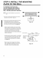
1. Find the points on the mounting plate labeled "A", "B", "C" and "D". Drill a 3/16" diameter hole at any of
these points that are in front of a wall stud. Drill a 3/4" diameter hole at any of these points that are over
drywall.
_,_ 2. Drill 3/8" hole at "J" and "K" the cabinet
a
points
on
upper
template.
NOTE: If the bottom of the upper cabinet is recessed 3/4" or more, you will need 2"x2" filler blocks (not
included) to provide additional support for the bolts. See Figure 24.
• Mark the center of each filler block and drill a 3/8" diameter hole at the mark.
• Align filler blocks over the two openings in the top of the microwave oven cabinet and attach to cabinet with
masking tape. See Figure 25.
3. Cut or drill a 2" diameter hole at the area marked "M", "power supply cord hole" on the upper cabinet template.
If the upper cabinet is metal, you will need to cover the edge of the hole with the power supply cord bushing
(supplied) to prevent damage to the cord from the rough metal edge.
WARNING
YOU MUST COVER THE EDGE OF
THE POWER SUPPLY CORD HOLE
IN A METAL CABINET WITH THE
POWER SUPPLY CORD BUSHING.
FAILURE TO DO SO COULD
RESULT IN DAMAGE TO THE CORD
AND ELECTRIC SHOCK.
cabinet front filler block
Figure 24
cabinet
bottomshelf
Cut out the venting areas (with the saber saw):
• Roof Venting: cut out the shaded area marked "L"
on the upper cabinet template.
• Wall or Room Venting (Recirculating): go to STEP
5, INSTALL THE MOUNTING PLATE, located on
page 15.
5. Use caulking compound to seal the exterior wall or
roof opening around the wall cap or roof cap.
filler
block
Figure 25
14

STEP 5: INSTALL THE MOUNTING
PLATE TO THE WA LL
THE OVEN MUST BE CONNECTED
TO AT LEAST ONE WALL STUD.
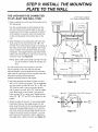
1. Draw a vertical line on the wall at the center of the
30" wide space.
Use the mounting plate as the template for the
rear wall. Place the mounting plate on the wall,
making sure that the tabs are against the bottom
of the cabinet. Line up the notch and center line
on the mounting plate to the center line on the
wall.
2. While holding the mounting plate with one hand,
draw circles on the wall at holes "A", "B", "C"
and "D". Four holes must be used for mounting. If
the holes are not used, the installation will not be
secure. Installer must use these holes for proper
installation. Use toggle bolts through these holes
unless one of them lines up with a stud. Use a lag
screw for studs. See Figure 26.
NOTE: Draw a fifth circle inside area "E", through
one of the holes to match the location of a
stud.
For wall vented: The oven requires a rear wall
cutout opening for the rear wall duct and the
exhaust adaptor must be attached to the mounting
plate. See the next page on how to prepare the rear
wall cutout opening and the exhaust
adaptor/mounting plate for wall vented.
3. Drill holes through the circles. If there is a stud,
drill a 3/16" hole for lag screws. Two or preferably
four lag screws at holes "A" and "C", or "B" and
"D" must be used to secure mounting plate to
wall. If there is no stud, drill a 3/4" hole for toggle
bolts. Make sure to use at least 1 lag screw at
holes of area "E" in a stud, and 4 toggle bolts at
holes "A", "B", "C" and "D" in the drywall or the
plaster.
4. Attach the plate to the wall. To use spring toggle
head bolts: Remove the toggle wings from the
bolts. Insert the bolts into the mounting plate and
replace the spring toggle heads to 3/4" past the
bolt ends. Insert the spring toggle heads into the
holes in the wall to mount the bracket. You may
pull forward on the bracket to help in tightening
the toggle bolts. Tighten all bolts. See Figure 27.
Minimum 66"
From the Floor
3/16" Hole on Studs
3/4" Hole on Drywall Only
I
t
I
I
/ Mounting
i []
Supper Tab
Figure 26
(----3
' t
Support Tab
-+-.
:1t gewngs
M°u_'tl_ ,, T°ggle B°lt t ,L
IIlA\
Space More Than Wall Thickness
Bolt
End
Figure 27
15

STEP 5: INSTALL THE MOUNTING
PLATE TO THE WALL
TO PREPARE THE REAR WALL
CUTOUT OPENING AND EXHAUST
ADAPTOR/MOUNTING PLATE FOR
WALL VENTING AND ROOF VENTING:
NOTE: If room vented installation is used, skip this
step.
1. Place the mounting plate against the rear wall as
described in step 5 item 1 (page 15).
2. Using a pencil, put dots through slots "F" and "G",
and through holes "H" and "1". Remove the
mounting plate and draw lines extending through
the points. This will give the location and size of the
box cutout for the rear wall duct. See Figure 28.
• Attach the exhaust adaptor to the rear mounting
plate by sliding it into the guides at the top center
of the plate on the wall side. Push in securely until
it is past the top locking tabs and in the lower
locking tabs. Take care to assure the damper
hinge is installed so that it is at the top and that the
damper swings freely.
• Carefully guide the exhaust adaptor, now attached
to the mounting plate, into the house duct, before
using the screws to attach the plate to the wall.
This will assure proper alignment for installation.
See Figure 29.
• Return to step 5, item 3 (page 15) to continue.
After completing the installation of the mounting
plate, again check the rear damper for free
movement to assure it will operate properly.
Figure 28
Exhaust Adaptor ._
Slide exhaust
adaptor into
guides on
rear panel.
Figure 29
Damper
(hinge side up)
Mounting Plate
(wall side)
Guides
16

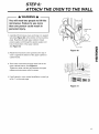
STEP 6:
A TTACH THE OVEN TO THE WALL
WARNING A
You will need two people to lift this
microwave. Failure to use more
than one person could result in
personal injury.
1. Carefully lift microwave oven and hang it on support
tabs (See Figure 26) at the bottom of the mounting
plate. Reaching through upper cabinet, thread
power supply cord through the power supply cord
hole in the bottom of the upper cabinet.
See Figure 30.
2. Rotate the microwave oven upward so the top of
oven is against the bottom of the upper cabinet or
cabinet frame.
3. Then insert a bolt down through each hole in the
upper cabinet bottom. See Figure 31.
Tighten the bolts until the gap between the upper
cabinet and microwave oven is closed.
__ power cord
Figure 30
4. If wall vented or room vented installation is used, go
to No. 7 on the next page.
Figure 31
17

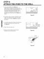
STEP 6:
ATTACH THE OVEN TO THE WALL
:T.
Roof vented installation: See Figure 32.
Install ductwork through the vent opening in the
upper cabinet. Complete the venting system through
the roof according to the method needed. See
"PREPARE THE VENTING SYSTEM," STEP 2 on
the page 8. Use caulking to seal exterior roof
opening around the exhaust cap. See Figure 6 on
page 8.
Use power supply cord clamp to bundle the power
supply cord. Install the power supply cord clamp,
using a screw as shown in Figure 33, to inside of
the cabinet.
7. To install the grease filter: Slide it into the slide slot,
then push up and toward oven center to lock.
See Figure 34.
8. Plug in the power supply cord.
9. Read your Owner's Manual, then check the
operation of your microwave oven.
domp I_
Figure 32
power
supply
cord
clamp
II,--
Figure 33
Figure 34
18

MEMO
19

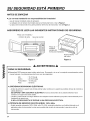
SU SEGURIDAD EST', PRIMERO
ANTES DE EMPEZAR
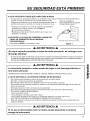
• iLa correcta instalacibn es responsabilidad del instalador!
- Lea el manual completo antes de empezar.
- La etiqueta con el numero de modelo esta en el frente del homo. Vea la Figura 1.
- La placa de montura esta en la parte posterior del homo de microonda. Vea la Figura 2.
ASEGURESE DE LEER LAS SIGUIENTES INSTRUCCIONES DE SEGURIDAD:
Placa con el modelo y
nQmero de serie Gufa de coccion
Figura 1
Placa de j
montura
(quitela del
horno para instalarlo)
Parte posterior
del homo
Figura 2
o
A ADVERTENCIA A
PARA SU SEGURIDAD:
• Necesitara DOS personas para instalar este homo. Es pesado y si no se Io manipula correctamente, podria
causar lesiones. Las dimensiones del homo son las siguientes:
Alto : 16-7/16 pulg
Ancho : 29-15/16 pulg
Profundidad : 15-3/8 pulg
Peso : 62 libras
• iPREVENGA DESCARGAS EL¢CTRICAS!
- Antes de perforar la pared note donde podrfan estar ocultos en la pared las posibles tomas de corriente y
cables electricos.
SE EXPONE A UNA DESCARGA ELleCTRICA si la boca de barrena de su taladro electrico hace
contacto con alguno de estos cables.
- Localice y desconecte la energfa electrica de cualquier circuito electrico que podria verse afectado por la
instalaci6n de este homo.
SI NO LOS DESCONECTA SE EXPONE A UNA DESCARGA ELleCTRICA.
• POTENCIA DE SERVICIO DE ESTE HORNO: 120V, 60Hz.
- Usted necesita solamente 120V, 60Hz, s61oCA, 20A, suministro electrico con fusible (ubicado en el
gabinete sobre el microondas Io m_.s cerca posible del circuito de microondas) y que sirva s61o al
microondas.
20

SU SEGURIDAD EST', PRIMERO
• iESTE ARTEFACTO DEBE SER CONECTADO A MASA!
- Si se produce un cortocircuito electrico, la conexion a masa reduce el riesgo de descarga electrica al
proveer un cable de escape para la corriente electrica. Este
artefacto esta equipado con un cable de alimentacidn que tiene un
alambre de masa en el enchufe con clavija de conexidn a masa.
• Coloque el enchufe en una toma de corriente correctamente
instalada con conexion a masa. Vea la Figura 3.
• No use cable de extensidn.
• Mantenga el cable de suministro electrico seco y que no se
pellizque o se aplaste.
TOMA DE CORRIENTE
ADECUADAMENTEPOLARIZADA
Y CONECTADA A MASA
• NO QUITE LA CLAVIJA DE CONEXION A MASA DEL
CABLE DE SUMINISTRO BAJO NINGUNA
CIRCUNSTANCIA!
Este artefacto DEBEser conectado a masa.
Enchufede tres clavijas (a masa)
Figura 3
ADVERTENCIA
iSi usa el enchufe conectado a masa de modo incorrecto, se arriesga a una
descarga el_ctrica!
- En caso de que usted no este seguro de que el homo se halle correctamente conectado a masa o en el caso de
no entienda completamente las instrucciones para conectar a masa compruebelo con un electricista calificado.
NO USE UN FUSIBLE EN EL CIRCUITO NEUTRO O DE MASA.
ADVERTENCIA A
La incorrecta conexibn a masa puede dar lugar a una descarga eldctrica u
otra lesibn personal.
GUARDE ESTAS INSTRUCCIONES PARA EL USO DEL INSPECTOR ELI_CTRICO LOCAL.
• iNO SE EXPONGA A LA EXCESIVA ENERGIA DE MICROONDA!
- NO trate de hacer funcionar el homo de microonda con la puerta abierta.
- NO altere o anule las cerraduras de seguridad.
- NO coloque objetos entre la cara delantera del homo de microonda y la puerta.
- NO permita que se amontone suciedad o residuos en las superficies planas alrededor de la puerta del
homo de microonda.
- NO haga funcionar el homo de microonda siesta daSado.
- El homo de microonda debe cerrarse correctamente para poder funcionar adecuadamente.
- NO USE EL HORNO DE MICROONDA:
• Si la puerta esta torcida.
• Si las bisagras o cerrojos estan rotos o flojos.
• Si los sellos hermeticos de la puerta, las superficies selladoras o el vidrio est_.n rotos.
- iNO TRATE DE REGULAR O REPARAR EL HORNO POR SU CUENTA!
Debe set regulado y reparado por un tecnico calificado que pueda comprobar las perdidas del homo
luego de repararlo.
A ADVERTENCIA A
Si no usa el microondas como se indica, puede exponerse a excesiva
energfa de microonda.
Zl
o
21

SU SEGURIDAD EST', PRIMERO
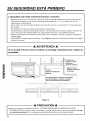
• ASEGURESE QUE TIENE SUFICIENTE ESPACIO Y SOPORTE
- Monte el homo contra una pared lisa, vertical, de modo que quede sostenido por esta pared. La pared
debe estar construida con un mfnimo de entramado de madera de 2" x 4" y un espesor de 3/8" de
mamposterfa o yeso/listones.
- Fije al menos uno de los tornillos de fijacion que soportan al homo a un poste de 2" x 4" del entramado
de la pared.
- No monte el homo de microondas sobre aislante o caja peninsul.
- AsegQrese que la estructura del gabinete superior y de la pared posterior puedan soportar 150 libras de
peso, mas el peso de cualquier objeto que coloque dentro del homo o en el gabinete superior.
- Ubique el homo lejos de corrientes de aire fuertes como por ejemplo, ventanas, puertas y respiraderos
de calor fuerte.
- ASEGORESE que tiene espacio suficiente. Vea la Figura 4 abajo para informarse del mfnimo de holgura
vertical y horizontal.
ADVERTENCIA A
Si no monta el horno como se indica, se arriesga a lesionarse y/o a dahar su
propiedad.
Zl
©
_._,
30" min.
Ancho de apertura de
gabinete
•Enchufe con
conexi6n a masa
(dentro del
gabinete superior)
Agujero para el
cable de suministro
de energia
la superficie de la cocina de la contratapa
(use las plantillas -modelos- incluidas
con las instrucciones de instalaci6n)
H
Ij i_J
Figura 4
_k PRECAUCION _k
• Antes de comenzar la instalaci6n del homo, COLOQUE UN PEDAZO DE CARTON O DE OTRO
MATERIAL APTO (una manta) sobre la contratapa o la parte superior de la cocina para protegerlo. No use
una cubierta de plaetico. El no proteger esas superficies puede terminar en daSos evitables.
22

PIEZAS, HERRAMIENTAS, MATERIALES
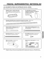
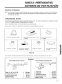
LAS SIGUIENTES PIEZAS SE ENTREGAN CON EL HORNO:
NOTA: Puede que usted no tenga que usarlas todas dependiendo de los requerimientos de ventilaci6n.
Regulador de tiro / conector del ducto
(para instalaci6n de ventilaci6n de techo o
de pared) El tamaSo que se presenta no es
el real
Una abrazadera para cable de
suministro de energia y un tornillo de
montaje de color oscuro
(para fijar el cordon
de suministro)
TamaSo real %
Una grapa portaorificio para el cable de suministro de energia. - TamaSo real
(Para el agujero del cable de suministro en un gabinete superior de metal.)
Cuatro tornillos de fijacion de 1/4" x 2" -
TamaSo real (para los agujeres en les
postes del entramado)
C
Dos pernos de 1/4" x 3" - TamaSo real.
(Para asegurar al gabinete superior)
Cuatro pernos de fiadores de 1/4" x 3" -
TamaSo real (para les agujeros en la pared
de mamposterfa)
Dos tornillos con rosca - TamaSo real
(para fijar el conecter de conducte de
humedad)
Fiador con resorte. - TamaSo real.
(para los pernos de palanca)
Modelo de Una Caja Superior - TamaSo
no real.
NOTA: Necesita instalar al menos uno de los tornillos de fijacion dentro de taco de 2"x 4" y cuatro pernos de
anclaje en la pared y el area de montaje debe Ilenar los requisites para sustentar las 150 libras de peso.
23

PIEZAS, HERRAMIENTAS, MATERIALES
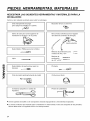
NECESITARA LAS SIGUIENTES HERRAMIENTAS Y MATERIALES PARA LA
INSTALACION:
Cart6n u otro material acolchado para cubrir la contratapa.
Cinta transparente de pegar
(para pegar las plantillas a la pared)
Buscador de taco o clave fine
Sierra de calar para cortar agujeros de
ventilacion en el techo o en la pared.
Destornillador Phillips (para los tornillos)
Lapiz
Destornillador de punta plana (para los
bulones) r_.,=_-..-._i
Broca hueca cilfndrica (para el agujero
del cable de suministro de energfa)
Mechas de perforacion para c_.._-"
madera de 3/8" y 3/4" "--_
Mechas de
perforaci6n
de 1/2" y 3/16"
=1
Zl
o
Cinta de medir (preferentemente de metal)
Plomada
Cinta para el ducto
Cortadoras peque5as o cizallas de
hojalatero
Pistola de calafeteado
• Si tiene paredes de ladrillo o de mamposteria necesita equipamiento y herramientas especiales.
• La red de conductos que necesita para la instalacion no esta incluida. Todos los casquetes en las paredes y
techos deben tener un regulador de tire con escape trasero.
24

PASO 1: PREPARAR LAS
CONEXIONES ELECTRICAS ADVERTENCIA
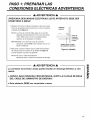
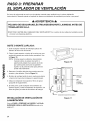
A ADVERTENCIA A
iPREVENGA DESCARGAS ELI_CTRICAS! iESTE ARTEFACTO DEBE SER
CONECTADO A MASA!
1. Ubique la toma de corriente conectada a tierra para este
horno en el gabinete encima del homo, como Io muestra
el detalle de la Figura 4.
NOTA: La toma de corriente debe estar en un circuito
dedicado exclusivamente al homo de microonda
120V, 60Hz, solo CA con un abastecimiento
electrico de 20 amperes con fusible.
IMPORTANTE: Si no tiene la toma de corriente
adecuado, usted DEBE hacer instalar uno per un
tecnico calificado.
2. Mas tarde, cortara el orificio para el cable de suministro
de energia (que se muestra en el detalle en Figura 4)
cuando prepare la pared y el gabinete.
NOTA: No use un cable de extensi6n.
Mantenga seco el cable de suministro de energfa.
Gabinete ii_
superior
i i
i,ii i
: Tomade
o I corriente
I aC°naesCt:da
Agujero para el cable
de suministro el_ctrico
Figura 4 (detalle)
A ADVERTENCIA A
La conexibn incorrecta a masa puede resultar en descarga eldctrica u otra
lesibn.
• iNUNCA, BAJO NINGUNA CIRCUNSTANCIA, QUITE LA CLAVIJA DE MASA
DEL CABLE DE SUMINISTRO DE ENERG|A!
• Este artefacto DEBE ser conectado a masa.
Zl
o
25

PASO 2: PREPARAR EL
SISTEMA DE VENTILACION
NOTA: La red de conductos que necesita para la ventilacion externa no esta incluida en el homo. Los
dispositivos de la red de conductos y Iongitud se muestran en la Figura 9, p_.gina 27.
,& ADVERTENCIA DE PELIGRO DE INCENDIO ,&
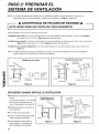
iESTE HORNO DEBE SER VENTILADO ADECUADAMENTE! 1
Puede ventilar su horno en una de estas tres formas:
Ventilacibn por techo Si su horno esta ubicado en una pared exterior cerca del techo, come en ias Figura 6
(un ducto de 3-1/4" x 10") y Figura 8 (ducte redendo de 6".)
Ventilacion por pared Si su homo est,. ubicado en una pared exterior en el primer piso de su casa como en las
Figura 5 (un ducto de 3-1/4" x 10") y Figura 8 (ducte redondo de 6".)
Ventilacion en la misma habitacion Si su homo est,. ubicado en una pared interior de su casa, como en ia
Figura 7.
NOTA: Si elige el metodo de escape (ventilaci6n per techo o per pared) asegQrese de que haya suficiente
espacio dentre de la pared para el ducto de ventilaci6n.
Zl
Ventilacion por pared
Gabin_
orn . ,, D__tode0,'
Casquete
para la
pared
A traves de la pared
Figura 5
Ventilacion por techo
Gabin_ °
Ho
Ventilaci6n
Casquete
para tech_
Ducto de
3-1/4"x10"
A trav_s de la pared
Figura 6
RECUERDE CUANDO INSTALE LA VENTILAClON:
• Mantenga ia iongitud de la red de
ductos
y el nQmero de codes a un mfnimo
para ventilar eficientemente su
horno. Vea ejemplos en pagina 27.
• Mantenga iguales los tamaSos de
los conductos.
• No instale dos codes juntos.
• Use la cinta de ductos para sellar
todas las juntas del sistema.
• Use calafateado para seiiar la
pared exterior o ia apertura de
techo alrededor del casquete.
Ventilacion en la
misma habitacion
Gabinete
Figura 7
Casquete
para techo
Ducto Redondq
de 6" diametro
mfnimo
Transici6n par_
ducto redondo
de 3-1/4"
la pared
Transici6nparasistemade
ductosredondosde3-1/4"
Figura 8
26

PASO 2: PREPARAR EL
SISTEMA DE VENTILACION
EQUIPOS ESTANDAR
NOTA: Si el conducto existente es redondeado, debe usar un adaptador cuadrado a redondo con una extension
de ducto de 3" instalada entre el conjunto de regulador de tiraje yel adaptador para prevenir el bloqueo
del regulador del tiraje.
LONGITUD DEL DUCTO
La Iongitud total del sistema de ductos, incluyendo el ducto recto, los codos las transiciones, casquetes de pared
o de techo, no deben exceder el equivalente de 140 pies.
Para un rendimiento mejor, no use m_.s de tres codos de 90 grados.
M_.s abajo se muestran los dispositivos est_.ndar ysu Iongitud equivalente en pies.
3-1/4"xl 0" Hasta 6"= 5pies Casquete de pared de 3-1/4"xl 0"
= 24 pies.
Codo 3-1/4"xl 0" 90°
= 25 pies.
Codo 90 ° = 10 pies. 3-1/4"x10" casquete
de pared = 40 pies.
Codo 45° = 5 pies. 3-1/4"xl 0" codo piano
= 10 pies•
Figura 9
Para calcular la Iongitud equivalente de cada pieza de ducto usada, ver los ejemplos de mas abajo.
Zl
o
Para sistemas de 3-1/4"x10"
Casquete
Code _---6 pies.---_ de pared
90_'3"1/4''x10''*_..[..T I _"
s.
Ejem
Codo 1 3-1/4" x 10" 90° = 25 pies.
1 casquete de pared = 40 pies.
8 pies de ducto recto = 8 pies.
LARGO TOTAL = 73 pies.
)los
Para sistemas redondos de 6"
• -- Casquete
Codes 90" _---6 ples.--_¢ de pared
Transici6r s.
1 transicibn = 5 pies.
2 codos 90° = 20 pies.
1 casquete de pared = 40 pies.
8 pies de ducto recto = 8 pies.
LARGO TOTAL = 73 pies.
27

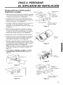
PASO 3: PREPARAR
EL SOPLADOR DE VENTILACION
Su homo de microonda se envia con el soplador montado para ventilaci6n en la misma habitacion
(recirculaci6n). Necesita ajustar el soplador si desea una instalacion de ventilaci6n por techo o por pared.
ADVERTENCIA
PELIGRO DE DESCARGAELI_CTRICA!DESENCHUFE LAUNIDAD ANTES DE
TRABAJAR EN ELLA.
• NO TIRE O ESTIRE DEL CABLEADO DEL VENTILADOR! Tirar o estirar de los cables del ventilador podia
provocar una descarga electrica.
QUITE O MONTE LAPLACA:
1. Quite cualquier material de embalaje ypiezas de
adentro del homo de microonda.
2. Cubra la parte superior o techo de la cocina con una
protecci6n gruesa para evitar daSos ysuciedad. Vea
la Figura 10.
NOTA: Si tiene espacio suficiente, desconectelo,
muevalo sobre un pedazo de cart6n o
aglomerado yalejelo de la pared, de modo
que usted pueda acercarse al gabinete
superior ya la pared de atras para perforar
ymedir mas f&cilmente.
3. Remueva 2 tornillos del plato de montaje como los
muestra y des echelos. (Vea la Figura 11.)
4. El plato de montaje tambi en ser Ausado para ubicar
y marcar los hoyos de montaje en la pared trasera.
5. Ubique el adaptador de expulsi6n, filtros de grasa
ypaquete de equipamiento.
6. En este punto, quite cualquier cinta adhesiva (si
hubiera alguna), sobre el adaptador de expulsi6n, los
filtros de grasa yel cable de suministro de energ[a.
INSTALACION DE VENTILACION EN
LAHABITACION:
Vaya al PASO 4, PREPARE LA PARED Y LA CAJA
SUPERIOR PARA LA INSTALACION ubicado en la
p_.gina 31.
Protecci6n gruesa
Figura 10
o
Placa de
montaje
---4
Placa de
montaje
(2 tornillos)
-- Costado del panel de control
Figura 11
28

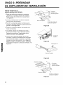
PASO 3: PREPARAR
EL SOPLADOR DE VENTILACION
INSTALACION DE LA VENTILACION A
TRAVI_S DE LA PARED:
Parte posterior
Unidad de soplador det horno
1. Retire dos tornillos de montaje de la unidad del ventilador
y un tomillo de la placa del ventilador. Retire la placa del
ventilador de la caja principal. Ver Figura 12.
2. Cuidadosamente levante la unidad del soplador hacia
afuera del homo de microonda. Desconecte el cable del
soplador del conector. Vea la Figura 13.
3. Use tijeras o cizallas de hojalata para cortar y quitar los
removibles "B" de la placa posterior. Descarte los
removibles. Tenga cuidado de no deformar la placa. Vea
la Figura 14.
4. Rote la unidad de modo que los puertos de expulsion
enfrenten la parte posterior del gabinete. Vea la Figura
15. Antes de inserte la unidad del soplador, el cable del
soplador debe quedar como se ve en la Figura 15.
5. Reensamble el cable del soplador dentro del conector.
6. Coloque de vuelta la unidad del soplador en el gabinete.
Compruebe que los puertos de expulsi6n enfrenten la
parte posterior del gabinete. Vea la Figura 16.
7. Reajuste la placa del soplador a la parte superior de la
caja como estaba armado orginalmente. Ajuste un tomillo
de montaje de la unidad del soplador y luego un tomillo
para la placa del soplador. Vea la Figura 17.
NOTA: AI utilizar la ventilaci6n de pared, usted necesita
un tornillo de montaje de la unidad del ventilador. Ver
Figura 17.
8. Vaya al PASO 4, PREPARE LA PARED Y LA CAJA
SUPERIOR PARA LA INSTALACION ubicado en la
p&gina 31.
Tornillo de
montaje de la
placa posterior
Removibles "B" -..
Placa del soptador
Tornillo de montaje de
la pIaca del soplador
Removibtes "B"
Conector
Figura 12
Cable del
soptador
Figura 13
Unidad
det soplador
Figura 14
Puertos de expulsi6n
Figura 16
Figura 15
_ ornillo de
montaje de la
placa det soplador
Puertos de _
expulsi6n de -_._._._j/.
la unidad det _"_L_----t_ ""
soplador
Tornillo de montaje de Ia
Unidad det soplador
Figura 17
29

PASO 3: PREPARAR
EL SOPLADOR DE VENTILACION
INSTALACION DE LA
VENTILACION POR TECHO:
1. Retire dos tornillos de montaje de la unidad del
ventilador y un tornillo de la placa del ventilador.
Retire la placa del ventilador de la caja principal.
Ver Figura 18.
2. Levante cuidadosamente la unidad del soplador
fuera del homo de microonda.
3. Rote 90 ° la unidad del soplador de modo que los
puertos de expulsion enfrenten la parte superior del
gabinete. Vea la Figura 19.
4. Coloque la unidad del soplador nuevamente en el
homo de microonda.
5. Use cizallas o tijeras para hojalata para cortar y
quitar los removibles "A" de la placa del soplador.
Descarte los removibles. Tenga cuidado de no
deformar la placa. Vea la Figura 20.
6. Vuelva a unir la placa del soplador al homo de
microonda. 0halo por medio del tornillo de montaje
de la unidad del soplador y luego los un tornillo de
montaje de la placa del soplador. Vea la Figura 21.
NOTA: AI utilizar la ventilaci6n superior, necesitara
un tornillo de montaje de la unidad del ventilador. Ver
Figura 21.
Tornillo de
montaje de la
placa dei soplador
PIaca det soplador
Tornillo de montaje de
Ia placa det soptador
Figura 18
det
soptador
Figura 19
Removibles "A"
/
Placa det soplador
Figura 20
Unidad de soptador
Tornillo de
montaje de la
placa det soplador
Placa_
Tornillo de montaje de
la placa det soplador
Figura 21
3O

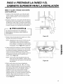
PASO 4: PREPARAR LA PARED YEL
f
GABINETE SUPERIOR PARA LA INSTALACION
MIDA Y CLAVE / PEGUE CON CINTA
LAS PLANTILLA
1. Usando un hilo de plomada y una cinta de medir
(metal), busque y marque la Ifnea vertical central
(_) en la pared posterior, como se muestra en la
Figura 22.
2. Busque y marque uno o dos puntos donde estan los
entramados de la pared (suelen estar a 16 pulgadas
de distancia) y luego mida y marque las ubicaciones
de los postes. Si no puede encontrar ningun poste en
la pared, consulte a un contratista local de edificios.
PRECAUCION
NO TRATE DE INSTALAR EL HORNO DE
MICROONDA SI NO HALLA UNA PARED DE
ENTRAMADO.
3. Alinee la Ifnea de plomada de la pared con la Ifnea
del centro de la placa de montaje.
NOTA: Asegurese de que el ancho mfnimo sea de
30 pulgadas y que la distancia desde la
parte superior de la placa de montaje hasta
la cara inferior o contratapa sea de al menos
30 pulgadas. Vea la Figura 4 en p&gina 25.
4. Centre el plato de montaje en la apertura alineando
la I fnea del plomo en la pared con la I fnea central
en el plato de montaje. Asegurese de que el ancho
mfnimo sea de 30 pulgadas y de que la parte
superior de la placa de montaje se halle al menos a
30 pulgadas por encima de la superficie de la
cocina. Vea la Figura 23.
NOTA: Si el borde frontal del gabinete esta mAs
abajo que el borde posterior, ajuste la placa
de montaje para que quede a nivel del frente
del gabinete.
5. Mida la parte inferior del marco del gabinete
superior. Centre los bordes "A", "B" y "C" de la
plantilla del gabinete superior de modo que quede
esta sobre la parte inferior del gabinete superior. Si
este gabinete tiene un marco rebajado, ajuste la
plantilla de modo que encaje dentro del &rea
rebajada. Alinee la Ifnea central de la plantilla del
gabinete superior con la Ifnea central de la placa de
montaje, luego asegure firmemente con cinta o
clave la plantilla del gabinete superior en su lugar.
Vea la Figura 23.
Figura 22
Figura 23
31

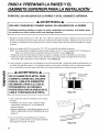
PASO 4: PREPARAR LA PARED YEL
GABINETE SUPERIOR PARA LA INSTALACION
PERFORE LOS AGUJEROS EN LA PARED Y EN EL GABINETE SUPERIOR.
ADVERTENCIA
SEA MUY CUIDADOSO CUANDO HAGA LOS AGUJEROS EN LA PARED.
Alambres eldctricos pueden no estar a la vista y embutidos en la pared y si el taladro entra
en contacto con ellos, podria recibir una descarga eldctrica.
Zl
Busque los puntos marcados con "A", "B", "C" y "D" en la placa de montaje. Taladre un hoyo de 3/16" de di
ametro en cualquiera de esos puntos que hay en frente de una pared montante. Taladre un hoyo de 3/16" de
di ametro en cualquiera de esos puntos que hay sobre la pared constru fdo de piedras encajadas sin mezcla
cohesive.
Perfore un agujero de 3/8" en los puntos "J" y "K" en la plantilla del gabinete superior.
NOTA: Si la parte inferior del gabinete superior esta rebajada en 3/4" o mas, necesitara 2"x2" de bloques de
relleno (no incluido) para dar soporte adicional a los pernos. Vea la Figura 24.
• Marque el centro de cada bloque de relleno y perfore un agujero de 3/8" de diametro en las marcas.
• Alinee los bloques de relleno sobre las dos aperturas en la parte superior del gabinete del homo de
microonda y fije al gabinete con cinta adhesiva. Vea la Figura 25.
3. Corte o perfore un agujero de 2" de diametro en el Area marcada "M", "agujero del cable de alimentaci6n" en
la plantilla del gabinete superior. Si el gabinete superior es de metal, necesitara cubrir los bordes del agujero
con un portaorificio (provisto) para evitar daSo en el cable producido por el borde irregular de metal.
ADVERTENCIA
EN UN GABINETE DE METAL DEBE
CUBRIR EL BORDE DEL AGUJERO
PARA EL CABLE DE SUMINISTRO
DE ENERG|A. PARA ELLO USE EL
PORTAORIFICIO. NO HACERLO
PUEDE RESULTAR EN DANOS EN EL
CABLE Y DESCARGA ELI_CTRICA.
Bloque del
Frente del filtro Estanteinferior
gabinete del gabinete
Figura 24
Corte y retire las Areas de ventilaci6n (con la sierra
de calar):
• Ventilado por el techo: Corte y quite las Areas
sombreadas marcadas "L" en la plantilla del
gabinete superior.
• Ventilar la habitaci6n o Pared (Recirculacion): Vaya al
PASO 5, INSTALAR LA PLACA DE MONTAJE, en la
pagina 33.
5. Use un compuesto de calafateado para sellar el
agujero en la pared exterior o en el techo alrededor
del casquete de pared o de techo.
Figura 25
Bloque
del filtro
32

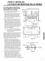
PASO 5: INSTALAR
LA PLACA DE MONTAJE EN LA PARED
EL HORNO DEBE ESTAR FIJADO
POR LO MENOS A UN POSTE DEL
ENTRAMADO DE LA PARED.
1. Trace una Ifnea vertical sobre la pared en el
medio del espacio de 30" de ancho.
Use la placa de montaje come plantilla para la
pared posterior. Coloque la placa de montaje
sobre la pared asegurandose que las aletas
queden contra la parte inferior del gabinete.
Alinee la ranura y la Nnea central sobre la placa
de montaje sobre la pared.
2. Mientras sostiene la placa de montaje con una
mane, marque cfrculos sobre la pared en los
agujeros "A", "B", "C" y "D". Deben usarse 4
agujeros para el montaje. Si no se usan estos
agujeros, la instalacion puede no ser segura, per
Io que el instalador debe usar todos enos para
una instalaci6n correcta. Use pernos de palancas
acodadas a traves de estos agujeros a menos
que uno de ellos este alineado con un poste del
entramado. En ese case use un tornillo de
fijaci6n. Vea la Figura 26.
NOTA: Trace un quinto cfrculo dentro del Area
"E", a traves de uno de los agujeros de
abajo para ajustarse a la ubicaci6n de un
poste del entramado.
Para homes ventilados a traves de la pared: el homo
necesita un agujero cortado en la pared posterior
para el conducto y para el adaptador de expulsion
que debe ser agregado a la placa de montaje. Vea
en la pr6xima pagina c6mo preparar el agujero de la
pared posterior y el adaptador expulsor/placa de
montaje para ventilacion por la pared.
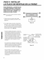
3. Taladre hoyos a trav es de los c frculos. Si
encuentra un poste del entramado, perfore un
agujero de 3/16" para un tornillo de fijaci6n. Si no
encuentra el entramado, perfore un agujero de
3/4" para los pemos de fiador. Deben usarse dos
o, preferiblemente, cuatro tornillos en los hoyos
"A" y "C" o "B" y "D" de cabeza cuadrada para
madera para fijar la placa de montaje de pared.
Asegt]rese de usar al menos 1 tornillo revestido
en los hoyos de la Area '<E" en un husillo, y
coloque 4 tomillos articulados en los hoyos "A",
"B", "C" y "D" en la pared constru fdo de piedras
encajadas sin mezcla cohesive o en el parche.
Agujeros de 3/16", sobre los tacos
Agujeros de 3/4", solamente sobre la mamposterfa
Unmfnimode
66"desdeel piso Solo par[a
en la pared
Figura 26
_Mas espacio que el espesor
de lapared
Alas delfiador
Placa de ttl I1 f Perno del ill. 1
m°ntaje"_lll::l! ,,, fiador II1:1.,
-llL!i,i\ _ lllJt\
4. Fije la placa a la pared. Para usar los pernos con
cabeza del fiador: Quite las cabezas con los
fiadores. Inserte los pernos en la placa de
montaje y vuelva a colocar las cabezas con los
fiadores luego de pasar los pernos per los
agujeros de 3/4". Inserte las cabezas con fiadores
en la pared para montar la mensula. Puede tirar
hacia delante la mensula para ayudar a ajustar
los fiadores. Ajuste todos los pernos. Vea la Figura 27.
Figura 27
Extremo
del pemo
33
Zl
o

PASO 5: INSTALAR
LA PLACA DE MONTAJE EN LA PARED
PARA PREPARAR LA APERTURA DE
LA PARED TRASERA Y EXPULSOR
ADAPTADOR/PLACA DE MONTAJE
VENTILACI ON DE LA PARED Y LA
VENTILACI ON DEL TECHO:
NOTA: Si es usado la aislaci 6n del techo ventilado,
ignore este paso.
1. Coloque la placa de montaje contra la pared
posterior como se describe en el PASO 5, item 1
(pagina 33).
Con un lapiz, marque con puntos a traves de las
ranuras "F" y "G" y a traves de los agujeros "H" e
"1". Quite la placa de montaje y trace una Ifnea que
pase pot esos puntos. Esto le precisara el tamaSo y
ubicaci6n del corte para la caja para el conducto de
la parte posterior. Vea la Figura 28.
;[; ; ; ;L;;;L;L;L;;;[:[; ; ;L;[;! _l
Figura 28
Zl
• Conecte el adaptador del expulsor a la placa de
montaje posterior deslizandolo en las gufas en los
topes centrales de la placa sobre la pared del
costado. Empt]jelo hasta asegurarlo hasta que
haya pasado los topes de bloqueo yen la parte
inferior en las lengL)etas de bloqueo. Tenga
cuidado de asegurar que la bisagra del regulador
de tiraje quede instalada de modo que se halle en
la parte superior y que el regulador se mueva
Nbremente.
• Con cuidado Ileve el adaptador del expulsor, ahora
agregado a la placa de montaje, en el alojamiento
del ducto antes de usar los tomillos para ajustar la
placa a la pared. Esto asegurara el correcto
alineamiento para la instalaci6n. Vea la Figura 29.
Adaptador de
expulsi6n _-
El adaptador _
de la guia de [_,_
deslizamiento
del expulsor i.._
en el panel ..._:/_"_
posterior. 0]_
o
Regulador detiraje
_._I_-._-'"- (lado de lasbisagras
_"_, hacia arriba)
_J Placa de montaje
_'_/jc._ (lade de lapared)
_..._- T.irasde \
° oierre
Guias
Figura 29
• Vuelva al PASO 5, item 3 (pagina 33) para
continuar. Luego de completar la instalacion de ia
placa de montaje, vuelva a comprobar el libre
movimiento del regulador de tiraje de la parte
posterior, para asegurarse que este funcionara
correctamente.
34

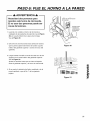
PASO 6: FIJE EL HORNO A LA PARED
_k ADVERTENCIA _k
Necesitard dos personas para
levantar este horno de microonda.
El no usar dos personas puede ser
causa de lesiones.
1. Levante con cuidado el homo de microonda y
cuelguelo de las pestaSas de soporte (vea la Figura
26) en la parte inferior de la placa de montaje.
Vea la Figura 30.
2. Gire el homo de microonda hacia arriba de manera
que la parte superior del mismo de contra la parte
inferior del gabinete superior o contra el marco del
gabinete.
Ii I
Cable de alimentaci6n
de energfa
Agujero para
el cable de
alimentaci6n
" de energfa
Figura 30
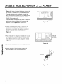
3. Luego inserte el tornillo a traves de cada uno de los
agujeros en la parte inferior del gabinete superior.
Vea la Figura 31.
Ajuste los torniilos hasta que se cierre el espacio
entre el gabinete superior y el homo de microonda.
4. Si es usado la aislaci6n del techo ventilado o de la
pared ventilado, vaya al No. 7 de la siguiente
pagina.
Figura 31
35

PASO 6: FIJE EL HORNO A LA PARED
Instalacion de la ventilaci6n por techo: Vea la
Figura 32. Instale el sistema de ductos a traves de
la apertura de ventilaci6n en el gabinete superior.
Complete el sistema de ventilaci6n a traves del
techo de acuerdo al metodo mas conveniente. Vea
"PREPARAR EL SISTEMA DE VENTILACION',
PASO 2. En la pagina 26.
Use material de calafateado para sellar la apertura
exterior en el techo alrededor del casquete de
expulsi6n. Vea la Figura 6 en la pagina 26.
Reguladordet je I_
Figure 32
Zl
Use la abrazadera para cable de suministro de
energia para enrollar este cable. Asegure la
abrazadera en el interior del gabinete usando el
tornillo de montaje como se muestra en la
Figura 33.
Para instalar el filtro de grasa. Desl[celo en la gu[a
de deslizamiento y luego emp0jelo hacia arriba y
hacia el centre del horno para asegurarlo. Vea la
Figura 34.
8. Enchufe el cable de provisi6n de energ[a electrica.
9. Lea su Manual de Usuario, luego controle el
funcionamiento de su homo de microonda.
Cable de
c_UminreiS;°
lit
Figure 33
Figure 34
36

E L I T E _R_
Printed in Korea
-
 1
1
-
 2
2
-
 3
3
-
 4
4
-
 5
5
-
 6
6
-
 7
7
-
 8
8
-
 9
9
-
 10
10
-
 11
11
-
 12
12
-
 13
13
-
 14
14
-
 15
15
-
 16
16
-
 17
17
-
 18
18
-
 19
19
-
 20
20
-
 21
21
-
 22
22
-
 23
23
-
 24
24
-
 25
25
-
 26
26
-
 27
27
-
 28
28
-
 29
29
-
 30
30
-
 31
31
-
 32
32
-
 33
33
-
 34
34
-
 35
35
-
 36
36
-
 37
37


Kenmore Elite 72180804400 Guía de instalación
- Tipo
- Guía de instalación
en otros idiomas
Artículos relacionados

Otros documentos
-
Kenmore 72162644200 Guía de instalación
-
Maytag Microwave Oven Electric Microwave Manual de usuario
-
Jenn-Air AMV4204AAW Guía de instalación
-
IKEA IMH172DS1 Guía de instalación
-
-
Bosch HMV3061U/01 Guía de instalación
-
GE Profile PVM9179EKES Guía de instalación
-
Electrolux EI30BM55HWB Guía de instalación
-
Frigidaire FGMV185KWA Guía de instalación
-
Whirlpool W11646788B Guía de instalación