Kenmore Elite 72187583610 Guía de instalación
- Categoría
- Microondas
- Tipo
- Guía de instalación
Este manual también es adecuado para

MFL69666101
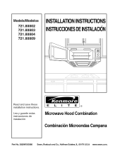
Installation Guide
Manual de Instalación
* = color number, número de color
www.sears.com
www.kenmore.com
ESPAÑOLENGLISH ESPAÑOLENGLISH ESPAÑOLENGLISH

– 2 –
Your Safety First
BEFORE YOU START
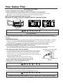
• Proper installation is the installer's responsibility!
Proper installation by a qualified technician or installer is recommended.
NOTE: Vent grille appearance varies by model.
BE SURE TO READ THE FOLLOWING SAFETY INSTRUCTIONS:
• Avoid Electric Shock!
– Before you drill into the wall, note where electrical outlets are and where electrical wires might be concealed
behind the wall. YOU COULD GET AN ELECTRIC SHOCK if you contact electrical wires with your drill bit.
– Locate and disconnect the power to any electrical circuits that could be affected by installing this oven.
IF YOU DO NOT DISCONNECT THE POWER, YOU COULD GET AN ELECTRIC SHOCK.
• ELECTRICAL RATING OF THIS OVEN : 120V AC 60Hz.
– You need a DEDICATED 120V, 60Hz, AC only, 15 or 20A, fused electrical supply (located in the cabinet
above the microwave as close as possible to the microwave) serving only the microwave.
Model Number Plate
Figure 1
For Your Safety
WARNING
Figure 2
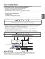
• THIS APPLIANCE MUST BE GROUNDED!
–
If there is an electrical short circuit, grounding reduces the risk of electric
shock by providing an escape wire for the electric current. This appliance
is equipped with a cord having a grounding wire with a grounding plug.
• Place the plug into a properly installed and grounded outlet. See Figure 3.
• Do not use an extension cord.
• Keep the power cord dry and do not pinch or crush it.
Failure to follow this instruction may cause a fire hazard.
• DO NOT, UNDER ANY CIRCUMSTANCES, REMOVE THE
POWER SUPPLY CORD GROUNDING PRONG!
This appliance MUST be grounded!
PROPERLY POLARIZED AND
GROUNDED OUTLET
Three-Pronged (Grounding) Plug
Figure 3
If you use the grounding plug improperly, you risk electric shock and/or fire!
Check with a qualified electrician if you are not sure whether the oven is properly grounded or if you do not
completely understand the grounding instructions.
DO NOT USE A FUSE IN THE NEUTRAL OR GROUNDING CIRCUIT.
Improper grounding could result in electric shock, fire or other personal injury.
– Read the entire manual before you begin. The model number label is located on the oven front.
See Figure 1. The mounting plate is located on WKHXSSHUSDFNLQJ. See Figure 2.
w
• This oven should not be installed or located by anyone except properly qualified service personnel.
• You will need TWO people to install this oven. It is heavy and could cause personal injury if not handled
properly.
WARNING
w
w
WARNING
Mounting Plate Mounting Plate
RU

Your Safety First
• MAKE SURE YOU HAVE ENOUGH SPACE AND SUPPORT.
– Mount the oven against a flat, vertical wall, so it is supported by the wall. The wall should be constructed of
minimum 2" x 4" wood studding and 3/8" thick drywall or plaster/lath.
– ATTACH (See note on page ) the two lag screws supporting the oven to a vertical, 2" x 4" wall stud.
– DO NOT mount the microwave oven to an island or peninsula cabinet.
– BE SURE the upper cabinet and rear wall structures can support 150 lb., plus the weight of any
items you place inside the oven or upper cabinet.
– Locate the oven away from strong draft areas, such as windows, doors, and strong heating vents.
– BE SURE you have enough space. See Figure 4 below for minimum vertical and horizontal clearance.
• Before you begin installing the oven, PLACE A PIECE OF THE CARTON OR OTHER HEAVY
MATERIAL (a blanket) over the countertop or cooktop to protect it. Do not use a plastic cover.
Failure to protect these surfaces could result in property damage.
30" min. cabinet opening width
30" min. clearance from bottom
of cabinet to cooking surface
or countertop before installation.
Grounded Outlet
(inside upper cabinet)
Power Supply Cord Hole
(Use templates included
with installation instructions)
If you do not mount the oven as instructed,
you risk personal injury and/or property damage.
NOTE: Maximum cabinet depth is 13".
SAVE THESE INSTRUCTIONS FOR THE LOCAL ELECTRICAL INSPECTOR'S USE.
• DO NOT EXPOSE YOURSELF TO EXCESSIVE MICROWAVE ENERGY!
– DO NOT try to operate the microwave oven with the door open.
– DO NOT tamper with or defeat the safety interlocks.
– DO NOT place objects between the microwave oven front face and the door.
– DO NOT allow soil or cleaner residue to build up on the flat surfaces around
– DO NOT operate the microwave oven if it is damaged.
– The microwave oven door must close properly to operate safely.
– DO NOT USE THE MICROWAVE OVEN:
the microwave oven door.
• If the door is bent.
• If the hinges or latches are broken or loose.
• If the door seals, sealing surfaces or glass is broken.
– DO NOT ATTEMPT TO ADJUST OR REPAIR THE OVEN YOURSELF!
It should be adjusted and repaired by a qualified technician who can check for microwave leakage after
repairing the oven.
If you do not use the microwave oven as instructed,
you could be exposed to excessive microwave energy.
WARNING
w
WARNING
w
w
CAUTION
– –
Figure 4
Slide-out hood model requires a minimum 2 in. distance
from the top of the range control panel to the bottom of microwave oven
2" min.
ENGLISHENGLISH

– 4 –
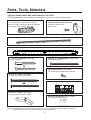
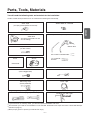
Parts, Tools, Materials
THE FOLLOWING PARTS ARE SUPPLIED WITH THE OVEN:
NOTE: Depending on your ventilation requirements, you may not use all of these parts.
Damper/duct connector
(for roof venting or wall venting installation)
Not Actual Size (2 pieces must be assembled as
shown) Not used if venting into kitchen.
One power cord clamp and
One dark-colored mounting screw
(to hold the power cord)
Actual Size
1/4" x 2" lag screws - Actual Size
(for wall stud holes)
Two 1/4" x 3" toggle bolts - Actual Size
(for drywall holes)
Two 1/4" x 3" bolts - Actual Size
(for securing to the upper cabinet
Two 1/4" x 3" bolts - Actual Size
(for securing to the upper cabinet)
Two tapping screws - Actual Size
(for attaching the damper/duct connector)
One upper cabinet template- Not Actual Size
One rear wall template- Not Actual Size
(1 piece mounting plate only)
One power cord clamp bushing - Actual Size (for the cord hole in a metal upper cabinet)
NOTE: You need to install at least one lag screw into a 2" x 4" stud and three anchor bolts into the wall.
and the mounting area must meet the 150 lb. weight requirement.
Two
)
One mounting plate - Not Actual Size (for supporting the Microwave Oven )
WARNING - TO REDUCE THE RISK OF FIRE AND ELECTRIC SHOCK,
INSTALL AT LEAST 13-3/4 INCHES ABOVE A COOKTOP(OR RANGE)
SUITABLE FOR USE ABOVE GAS OR ELECTRIC
COOKING EQUIPMENT 36 INCHES OR LESS WIDE.
APTO PARA SU USO SOBRE EQUIPOS ELÉCTRICOS O
A GAS CON ANCHO DE 36 PULGADAS (90CM) O INFERIOR
ADVERTENCIA - PARA REDUCIR EL RIESGO DE INCENDIO Y DE DESCARGA ELÉCTRICA,
INSTALE AL MENOS A 13-3/4 PULGADAS (35CM) SOBRE LA VITROCERÁMICA (O FOGÓN)

– –
Parts, Tools, Materials
Clear Tape
(for taping the templates to the wall)
Phillips Screwdriver
(for the screws)
Gloves
Pencil
Flat Blade Screwdriver
(for the toggle bolts)
Plumb Line
Measuring Tape
(metal preferred)
Duct Tape
Caulking Gun and Caulk
Stud Finder or Thin Nail
Saber Saw
(for cutting vent holes for roof
or wall venUing)
Keyhole Saw (for the power cord hole)
You will need the following tools and materials for the installation:
Carton or other heavy material such as a blanket for covering the counter top.
3/8" and 3/4" wood drill bits
1/2" and 3/16"
drill bits
Electric Drill
Small Side Cutters1LSSHU or Tin Snips
If you have brick or masonry walls, you will need special hardware and tools.
The ductwork you need for the installation is not included. All wall and roof caps must have a back-draft damper.
(Shown on page ).
Wear proper gloves to protect your hands from injury.
ENGLISHENGLISH

– –
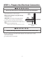
STEP 1: Prepare Uhe Electrical Connection
Improper grounding could result in electric shock or other personal injury.
1. Locate the grounded electric outlet for this oven in the
cabinet above the oven, as shown in Figure 5.
NOTE: The outlet should be on a circuit dedicated to the
microwave oven (120V, 60 Hz., AC only) with a 15 or 20A
fused electrical supply.
IMPORTANT: If you do not have the proper wall outlet,
you MUST have one installed by a qualified electrician.
2. You will cut the hole for the power supply cord (shown in
Figure 5) later when you prepare the wall and upper cabinet in
Step 4.
NOTE: Do not use an extension cord.
Keep the power cord dry and do not pinch or crush it.
DO NOT, UNDER ANY CIRCUMSTANCES, REMOVE THE POWER SUPPLY CORD
GROUNDING PRONG!
This appliance MUST be grounded!
AVOID ELECTRIC SHOCK! THIS APPLIANCE MUST BE GROUNDED!
Upper
Cabinet
Power-Supply-Cord Hole
Figure 5
Grounded Outlet
(Inside Cabinet)
WARNING
w
WARNING
w

– –
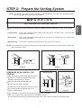
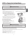
STEP 2: Prepare Uhe Venting System
THIS OVEN MUST BE PROPERLY VENTED!
NOTE: The ductwork you need for outside ventilation is not included with your oven. The standard ductwork
fittings and length are shown in Figure 10, page .
You may vent your oven in one of three ways. However, do NOT vent into a wall cavity, an attic, or an unused
area.
Roof-venting If your oven is located on an outside wall near the roof, as in Figure 7 (3 1/4" x 10" duct) and
Figure 9 (6" round duct.)
Wall-venting If your oven is located on an outside wall of your house, as in Figure 6 (3 1/4" x 10" duct) and
Figure 9 (6" round duct.)
Room-venting If your oven is located on an inside wall of your house, as in Figure 8.
NOTE: If you choose the rear exhaust method (roof or wall-venting), be sure there is enough clearance within the
wall for the exhaust duct.
REMEMBER AS YOU INSTALL THE
VENTING:
Keep the length of the ductwork and the number
of elbows to a minimum to ventilate your oven
efficiently. See examples on page .
Keep the size of the ductwork the same.
Do not install two elbows together.
Use duct tape to seal all joints in the duct system.
Use caulking to seal the exterior wall or roof
opening around the cap.
Cabinet
Oven
Wall Mounting
Through-the-wall Duct
Wall Cap
3 1/4"x10"
Duct
Cabinet
Oven
Figure 6
Wall Venting
Through-the-roof
3 1/4"x10"
Duct
Roof Cap
Roof Venting
Cabinet
Oven
Figure 7
Roof Venting
Figure 8
Room Venting
6"min diameter
Round Duct
3 1/4" to Round
Duct Transition
3 1/4" to Round
Ductwork Transition
Roof Cap
Wall Cap
Elbow
Figure 9
WARNING
w
$IWHULQVWDOODWLRQ\RXVKRXOGFKHFNRXWVLGHKRRGRSHQLQJDQGRSHUDWLRQ
:KHQ\RXLQVWDOOWKHRYHQSOHDVHUHIHUWRWKH,QVWDOODWLRQ0DQXDO
)RUWKHRXWVLGHKRRGRSHQLQJSRVLWLRQDQGVL]HUHIHUWRWKHXSSHUFDELQHWWHPSODWHRUUHDUZDOOWHPSODWH
ENGLISHENGLISH

– –
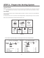
STEP 2: Prepare Uhe Venting System
Standard Fittings
NOTE: If the existing duct is round, you must use a rectangular-to-round adapter, with a rectangular 3" extension
duct installed between the damper assembly and the adapter to prevent the exhaust damper’s sticking.
Duct Length
The total length of the duct system, including straight duct, elbows, transitions, and wall or roof caps must not
exceed 140 feet.
For best performance, do not use more than three 90 degree elbows, and keep the length as short as possible.
Below are the standard fittings and their equivalent length in feet.
To calculate the equivalent length of each duct piece used, see the examples below.
Figure 10
6ft.
2ft.
2ft.
wall cap
6ft.
transition
wall cap
For 3 1/4" x 10" SYSTEMS
1 3 1/4” x 10” 90° elbow = 25 ft.
1 Wall Cap = 40 ft.
8 feet straight duct = 8 ft.
TOTAL LENGTH = 73 ft.
1 transition = 5 ft.
2 90° elbows = 20 ft.
1 Wall Cap = 40 ft.
8 feet straight = 8 ft.
TOTAL LENGTH = 73 ft.
For 6" ROUND SYSTEMS
3 1/4” x 10”
to 6" = 5 ft.
90˚elbow
= 10 ft
45˚elbow
= 5 ft
3 1/4” x 10”
wall cap
= 40 ft
3 1/4” x 10”
flat elbow
= 10 ft
3 1/4” x 10” roof
cap = 24 ft
3 1/4” x 10” 90˚
elbow = 25 ft
1 2 3
4 5 6 7
Examples

– –
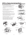
STEP 3: Prepare Uhe Venting Blower
Your microwave oven is shipped with the blower assembled for URRIventing. You need to adjust the blower if you
want wall-venting or room-venting installation.
• DO NOT PULL OR STRETCH THE BLOWER WIRING! Pulling and stretching the blower wiring could result in
electric shock.
1. Remove any shipping materials and parts from inside the
microwave oven. Set them aside for later use.
2. Cover the counter top or cooktop with a thick, protective
covering to protect it from damage and dirt. See Figure 11.
NOTE: If you have a free-standing range, disconnect
it, move it onto a piece of cardboard or hardboard and
pull it away from the wall, so that you can get closer to
the upper cabinet and back wall for easier measuring
and drilling.
. Locate UIFexhaust adaptor, grease filters and hardware packet.
. At this point, remove any adhesive tape (if there is any), on the
exhaust adaptor, the grease filters and the power supply cord.
522)-9ENT,1* INSTALLATION:
This oven is shipped assembled for roof-venting.
. Insert the tabs on each side of the damper into the holes
at the inside rear of the adaptFr.
Attach the exhaust adaptFr to the blower plate with the two
tapping screws provided. See Figure 12.
Make sure that the damper swings freely.
A thick, protective
covering
Figure 11
ELECTRIC SHOCK HAZARD! UNPLUG UNIT BEFORE WORKING ON IT.
WARNING
w
w
WARNING
),5(+$=$5'&255(&7/<,167$//7+(9(17)$1%()25(86(.
•
When changing the vent fan position forB rear wall vent or room vent:
1. Properly align the ventilation fan openings and blower plate knockouts.
2. Ventilation fan openings should be completely exposed to the outside.
•
*NQSPQFS installation can cause problems such as:
1. Inability to assemblF blower plate or ventilation motor correctly.
2. Abnormal noise during product operation.
3. Weak ventilation.
4. Product overheating - possibility of product breakdown or fire.
Figure 1
Damper
Back of
Oven
Exhaust
Adapter
Blower Plate
. $IWHULQVWDOODWLRQFKHFNWKHDLUYHQWLODWLRQSDWK5HIHUWRSDJH)LJXUHVIRUSURSHUYHQWVHOHFWLRQ
127(6HWWKHSURGXFWGRZQRQDIODWVXUIDFHRQO\
• 'RQRWUHPRYHWKHSDFNLQJWDSHRQWKHVOLGHRXWYHQW
ENGLISHENGLISH

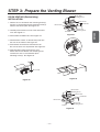
STEP 3: Prepare Uhe Venting Blower
WALL-VENT,1* INSTALLATION:
1. Remove one or two blower unit mounting screw(s) and one
or several blower plate mounting screw(s). Remove the
blower plate from UIFcabinet. See Figure 1.
2. Carefully lift the blower unit out of the microwave oven.
3. Use side cutters or tin snips to cut and remove knockouts
B from Back plate. Discard knockouts. Be careful not to
distort the plate. See Figure 1.
4. Reassemble the blower wire. See Figure 1.
5. 3PUBUFBOESFJOTUBMMUIFCMPXFSVOJUTPUIBUUIFFYIBVTU
QPSUTGBDFUIFSFBSof the cabinetBOEBSFBMJHOFEXJUIUIF
SFBSDVUPVUT4FF'JHVSFT
. Reattach the blower plate to microwave oven so the exhaust
ports and blower plate opening are aligned. Attach with one
blower unit mounting screw and then one or several blower
plate mounting screw(s). See Figure 1.
. Insert the tabs on each side of the damper into the holes
at the inside rear of the adaptFr.
Attach the exhaust adaptFr to the EDFNSODWHZDOOVLGH
Push in securely until it is past theWRSORFNLQJWDEV
and in the lower locking tabs. Take care toDVVXUH
the damper hinge is installed so that it is at the top
and that the damper swings freely. 6HH)LJXUH
Figure 1
Blower Plate
Mounting Screw
Blower Plate
Back Plate
Blower Unit
Mounting Screw
Blower Unit
Parts B
Figure 1
Blower
Unit
Exhaust Ports
Figure 1
Figure 1
Figure 1
Blower Plate
Mounting Screw
Blower Plate
Back Plate
Blower Unit
Exhaust Ports
Blower Unit
Blower Unit
Mounting Screw
Figure 1
Exhaust
Ports
– 1 –
Slide exhaust
adaptor into
guides on
rear panel.
Exhaust AdaptFr
Damper
(hinge side up)
Locking
Tabs
Guides
Figure
See Figure .
Parts B
Knockouts Parts B
Figure
RU

STEP 3: Prepare Uhe Venting Blower
– 1 –
ROOM-VENTING (Recirculating)
INSTALLATION:
1. Remove one or two blower unit mounting screw(s)
and one or several blower plate mounting screw(s).
Remove the blower plate. See Figure2.
2. Carefully lift the blower unit out of the microwave
oven.
4. Rotate blower unit 90° so the exhaust ports face
the front of the cabinet. See Figure 2.
. Reattach blower plate to microwave oven.
Attach with the one blower unit mounting screw
and then the one or several blower plate
mounting screw(s). See Figure 2.
Figure
Figure 2
Blower Plate
Mounting Screw
Blower Plate
Back Plate
Parts B
Blower Unit
Figure 2
Blower Unit
Blower Unit
Mounting Screw
Blower Plate
Mounting Screw
Blower Plate
Back Plate
Blower Unit
Mounting Screw
Blower Unit
Parts B
. Place blower unit back into PLFURZDYHRYHQ.
Be sure thewires are not pinched. See Figure .
. Reassemble the blower wire. See Figure .
Figure 2
Figure
See Figure .
ENGLISHENGLISH

– 1 –
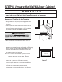
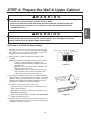
STEP 4: Prepare Uhe Wall & Upper Cabinet
To avoid personal injury or property damage, do not attempt to install this microwave
oven if you cannot find a wall stud. Consult a carpenter or contractor.
0RXQWLQJ3ODWH
Measure and Tack/Tape Up the Templates
1. Using a plumb line and (metal) measuring tape, find and
mark the vertical center line on the back wall, as in
Figure 26.
2. Find and mark one or two points where the studs are on
the wall. (Studs are normally 16 inches apart). Then
measure and mark the stud locations. If you cannot find
any wall stud, consult a local building contractor.
3. 'UDZDYHUWLFDOOLQHRQWKHZDOODWWKHFHQWHURIWKHƎ
ZLGHVSDFH.
NOTE: Be sure the minimum width is 30 inches
DO NOT ATTEMPT TO INSTALL THE MICRO-
WAVE OVEN IF YOU CANNOT FIND A WALL
STUD.
CAUTION
Figure
Figure
4. CenterWKHUHDUZDOO WHPplate in UIFTQBDF by lining up the
plumb line on wall with centerline on WHPplate.7KHQVHFXUHO\
WDSHRUWDFNWKHUHDUZDOOWHPSODWHLQSODFHMake sure the
minimum width is 30 inches and that thetop of the UHDU
ZDOOWHPSODWHLVORFDWHGDPLQLPXPRILQFKHVDERYH
the cooking surface. See Figure 2.
NOTE: If the cabinets are not plumb, adjust the UHDUZDOO
WHPplate to the cabinets. If the front edge of the
cabinet is lower than the back edge, adjust the
WHPplate to be level with the cabinet front.
5. Measure the bottom of the upper cabinet frame. Trim
edges A, B, and C on the upper cabinet template
so that the template will fit on the bottom of the upper
cabinet. If upper cabinet has a recessed frame, trim the
template so it fits inside the recessed area. Align the
centerline of the upper cabinet template with the
centerline of the UHDUZDOOWHPplate, then securely tape or
tack the upper cabinet template in place. See Figure
WARNING
w
w
Upper CabinetTemplate

– 1 –
STEP 4: Prepare Uhe Wall & Upper Cabinet
Drill Holes in the Wall and Upper Cabinet
1. Drill holes on the circles. If there is a stud, drill a 3/16
"
hole
for lag screws. If there is no stud, drill a 3/4
"
hole for toggle
Filler Block
Cabinet
Cabinet Front
Bottom Shelf
bolts. Make sure to use at least 1 lag screw in a stud, and
2 toggle screws in the drywall or the plaster.
2. Drill a 3/8” hole at points J and K on the upper cabinet
template.
NOTE: If the bottom of the upper cabinet is recessed 3/4
"
or more, you will need 2
"
x 2
"
filler blocks (not
included) to provide additional support for the bolts.
Figure 28
See Figure 28.
Mark the center of each filler block and drill a 3/8”
diameter hole at the marks.
Align filler blocks over the two openings in the top
of the microwave oven cabinet and attach to the
cabinet with masking tape. See Figure 29.
3. Cut or drill a 2
"
diameter hole at the area marked "M power
supply cord hole" on the upper cabinet template. If the upper
Filler
cabinet is metal, you will need to cover the edge of the hole
Block
with the power supply cord bushing (supplied) to prevent
damage to the cord from the rough metal edge.
4. Cut out the venting areas (with a saber saw):
Roof-Venting: cut out the shaded area marked L on the
upper cabinet template.
Wall-Venting: Cut out the shaded area marked F on the
REAR WALL TEMPLATE.
Room-Venting: go to STEP 5, INSTALL THE MOUNTING
Figure 29
PLATE, located on page 14.
5. Complete whichever venting system you have chosen. Use
caulking compound to seal the exterior wall or roof opening
around the wall cap or roof cap.
To avoid risk of personal injury, electric shock or death:
Note where electrical outlets and electrical wires are before you drill into the wall.
Locate and disconnect power to any electrical circuits that could be affected by
installing this oven.
To avoid risk of personal injury, electric shock or death, cover the edge of the power
supply cord hole with the power supply cord bushing.
WARNING
w
WARNING
w
ENGLISHENGLISH

– 14 –
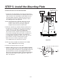
STEP 5: Install the Mounting Plate
C
B
A
Connect the Oven to at Least One Wall Stud.
4. Attach the plate to the wall. To use spring toggle head bolts:
Remove the toggle wings from the bolts. Insert the bolts into
the mounting plate and replace the spring toggle head to 3/4
past the bolt ends. Insert the spring toggle head into the
holes in the wall to mount the plate. You may pull forward on
the plate to help in tightening the toggle bolts. Tighten all
bolts. See Figure 31.
3. Remove the template from the rear wall.
1. Center the rear wall template in the space by lining up the
plumb line on wall with centerline on template.Then securely
tape or tack the rear wall template in place.Make sure the
minimum width is 30 inches and that the top of the rear
wall template is located a minimum of 30 inches above
the cooking surface. See Figure 26.
NOTE: If the cabinets are not plumb, adjust the rear wall
template to the cabinets. If the front edge of the
cabinet is lower than the back edge, adjust the
template to be level with the cabinet front.
a stud. If there is a stud, drill a 3/16 hole for lag screws.
If there is no stud, drill a 5/8 hole for toggle bolts.
These holes must be used for mounting. If the holes are
not used, the installation will not be secure. Installer must
use these holes for proper installation. See Figure 30.
Use toggle bolts through these holes, unless one of them
lines up with a stud. Use a wood screw for studs.
Make sure to use at least 1 lag screw in a stud,
and 2 toggle bolts in the drywall or the plaster.
2. Drill holes at points A, B. Drill the third hole inside area C,
through one of the bottom holes to match the location of
NOTE: Cut out the shaded area marked F on the REAR
WALL TEMPLATE for wall-venting.
Figure 31
Figure 30
Wall
Mounting
Plate
Space More Than Wall Thickness
Bolt
End
Toggle Bolt
Toggle Wings1
3/16 Hole on Studs
5/8 Hole on Drywall Only
Minimum 66
From the Floor
For Wall -
Venting Only
Draw Lines
on Studs
Draw
Center Line
Center Line
Mounting Plate
Support Tab
Support Tab

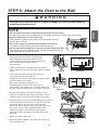
STEP 6: Attach the Oven to the Wall
1. Carefully lift microwave oven and hang it on support tabs
(See Figure at the bottom of the mounting
plate.Reaching through upper cabinet, thread
power supply cord through the power supply cord
hole in the bottom of the upper cabinet.
See Figure 3
2. Rotate the microwave oven upward so the top of UIF
oven is against the bottom of the upper cabinet or cabinet
frame.
3. Then insert a bolt down through each hole in the
upper cabinet bottom.See Figure 3.
Tighten the bolts until the gap between the upper cabinet
and microwave oven is closed.
Figure 3
Figure 3
Power Cord
Power Cord
Hole
To avoid risk of personal injury or property damage, you will need two people to
install this microwave oven.
WARNING
4. Roof venting installation: See Figure 3.
Install ductwork through the vent opening in the
upper cabinet. Use caulking gun to seal the exterior roof
opening around the exhaust cap. See Figure 7 on page 7.
5. Use the power supply cord clamp to bundle the power
supply cord. Install the power supply cord clamp, using a
screw as shown in Figure 3, to the inside of the cabinet.
6. Grasp the filter screen with one hand holding the ring and the
other hand holding the opposite end. Insert the end of the
filter screen without ring into the opening and slide
towards the side of the microwave oven. Insert ring end of
filter screen into the opening and slide entire screen
towards the center of the microwave until screen is
securely in position. Repeat for other filter screen. See
Figure 3.
7. Plug in the power supply cord.
8. Read your Owner’s Manual, then check the operation of
your microwave oven.
Damper
Power
supply
Cord
Clamp
Figure 3
Figure 3
Figure 3
– –
w
NOTE:
ƔDo not apply force directly to the outside bottom surface of the product.
The slide-out vent latch may be damaged if force is applied directly to the center bottom of the product.
Ɣ6HWWKHSURGXFWGRZQRQDIODWVXUIDFHRQO\
During unpacking, gently set the product onto a flat surface such as a
kitchen table or counter.
Ɣ'RQRWOLIWRUVXSSRUWWKHSURGXFWE\WKHERWWRPFHQWHUVXUface.
The product is best handled by the bottom sides near the legs.
Ɣ'RQRWUHPRYHWKHSDFNLQJWDSHRQWKHVOLGHRXWYHQWGXULQJ
installation.
Once the product is fully installed, remove the tape and check that the vent
easily slides open and closed with a push.
1
2
3
1
2
ENGLISHENGLISH

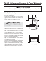
Su Seguridad Ante Todo
ANTES DE COMENZAR
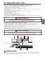
• La instalación correcta es responsabilidad del instalador!
Se recomienda una instalación adecuada por un técnico o instalador autorizado.
NOTE: El aspecto de la rejilla de ventilación varía según el modelo.
ASEGÚRESE DE LEER LAS SIGUIENTES INSTRUCCIONES DE SEGURIDAD:
Placa Modelo Número
Ilustración 1
Para Su Seguridad
ADVERTENCIA
ADVERTENCIA
Ilustración 2
Este aparato DEBE conectarse a tierra!
TOMACORRIENTE POLARIZADO
Y ADECUADAMENTE CONECTADO
A TIERRA
Enchufe de tres patas (tierra)
Ilustración 3
Si utiliza el enchufe de conexión a tierra incorrecto, corre el riesgo de descarga
eléctrica y/o incendio!
Consulte con un electricista autorizado si no está seguro de si el horno está correctamente conectado a tierra o si no entiende
completamente las instrucciones de conexión a tierra.
NO USAR UN FUSIBLE EN EL CIRCUITO NEUTRAL O DE CONEXIÓN A TIERRA.
Una conexión a tierra incorrecta podría provocar descargas eléctricas, incendios u
otros daños personales.
• Este horno no deberá ser instalado o colocado por nadie excepto personal de servicio autorizado.
• Se necesitan DOS personas para instalar este horno. Es pesado y podría causar daños personales si no
se maneja adecuadamente.
• Evitar la Descarga Eléctrica!
• CLASIFICACIÓN ELÉCTRICA DE ESTE HORNO : 120V AC 60Hz.
ADVERTENCIA
Placa de fijación Placa de fijación
- Antes de taladrar en la pared, averiguar dónde pueden estar ocultos detrás de la pared los enchufes eléctricos y cables
eléctricos. USTED PODRÁ RECIBIR UNA DESCARGA ELÉCTRICA si su broca entra en contacto con los cables eléctricos.
- Localizar y desconectar la alimentación de los circuitos eléctricos que podrían verse afectadas por la instalación de este horno.
EN CASO DE NO DESCONECTAR EL SUMINISTRO ELÉCTRICO, PODRÍA RECIBIR UNA
DESCARGA ELÉCTRICA.
– Lea el manual completo antes de comenzar. La etiqueta con el número de modelo se encuentra en la parte frontal del horno.
Consultar Ilustración 1. La placa de fijación se encuentra en el embalaje superior. Consultar Ilustración 2.
- Es necesario UNA LÍNEA de 120 V, 60 Hz, AC únicamente, 15 o 20A de suministro
eléctrico con fusible (situado en el armario encima del microondas lo más cerca posible
del microondas) atendiendo solamente al microondas.
• ESTE APARATO DEBE CONECTARSE A TIERRA!
• NUNCA, BAJO NINGUNA CIRCUNSTANCIA, RETIRAR LA
CLAVIJA DE CONEXIÓN A TIERRA DEL CABLE DE ALIMENTACIÓN!
- En caso de cortocircuito eléctrico, la conexión a tierra reduce el riesgo de descarga
eléctrica proporcionando un conductor de escape para la corriente eléctrica. Este
aparato está equipado con un cable que tiene un conductor de conexión a tierra con un
enchufe de conexión a tierra.
s#OLOQUEELENCHUFEENUNATOMADECORRIENTECONCONEXIØNATIERRA#ONSULTAR
Ilustración 3.
s.OUTILICEUNCABLEALARGADOR
s-ANTENGAELCABLEDEALIMENTACIØNSECOYNODA×AROAPLASTARLO
El incumplimiento de esta instrucción puede provocar un riesgo de incendio.
- 2 -

Su Seguridad Ante Todo
Toma de corriente con conexión a tierra
(interior del armario superior)
Orificio del Cable de Alimentación
NOTA: La profundidad máxima del armario es de 13".
GUARDE ESTAS INSTRUCCIONES PARA EL USO DE INSPECTORES ELÉCTRICOS LOCALES.
Si no se utiliza el horno de microondas según las instrucciones,
podría exponerse a una excesiva energía de microondas.
ADVERTENCIA
PRECAUCIÓN
Ilustración 4
El modelo de campana deslizable requiere de una distancia mínima de 2 pulgadas desde la
parte superior del rango del panel de control hasta la parte inferior del horno microondas.
2"min.
• NO SE EXPONGA EXCESIVAMENTE A LA ENERGÍA DE MICROONDAS!
• ASEGURESE DE TENER SUFICIENTE ESPACIO Y APOYO.
– NO intente hacer funcionar el horno de microondas con la puerta abierta.
– NO manipular o anular a los bloqueos de seguridad.
– NO coloque objetos entre el lado frontal del horno microondas y la puerta.
– NO permita que suciedad o residuos de productos de limpieza se acumulen en las superficies planas alrededor de la puerta
del horno microondas.
– NO haga funcionar el horno microondas si está dañado.
– La puerta del horno de microondas debe cerrar correctamente para funcionar con seguridad.
– NO USAR EL HORNO DE MICROONDAS:
s3ILAPUERTAESTÈDOBLADA
s3ILASBISAGRASYCERRADURASESTÈNROTASOSUELTAS
s3IPUERTACIERRASUPERFICIESDESELLADOOVIDRIOESTÈNROTOS
– NO INTENTE AJUSTAR O REPARAR EL HORNO USTED MISMO!
Deberá ser ajustado o reparado por un técnico autorizado que pueda comprobar si existan fugas de microondas después de
reparar el horno.
n-ONTARELHORNOENUNAPAREDPLANAYVERTICALDEMODOQUESEQUEDAAPOYADAPORUNAPARED,APAREDDEBERÈESTAR
construido con un mínimo de 2 "x 4" de entramado de madera y cartón yeso de espesor de 3/8 " o yeso/listón.
n&)*!26EALANOTAENLAPÈGINALOSDOSTORNILLOSDECOMPRESIØNQUESOPORTANELHORNOAUNMONTANTEDEXVERTICAL
– NO instale el horno de microondas a una isla o un armario de península.
n!3%'Á2%3%DEQUEELARMARIOSUPERIORYLASESTRUCTURASDELAPAREDTRASERAPUEDENSOPORTARLBMÈSELPESODELOS
artículos que coloque en el interior del horno o armario superior.
n#OLOCARELHORNOLEJOSDEZONASDEFUERTESCORRIENTESFUERTESTALESCOMOVENTANASPUERTASYFUERTESSALIDASDECALEFACCIØN
n!3%'Á2%3%DETENERESPACIOSUFICIENTE#ONSULTE)LUSTRACIØNABAJOPARACONOCERELDESPACHOVERTICALYHORIZONTALMÓNIMO
s!NTESDECOMENZARCONLAINSTALACIØNDELHORNO#/,/15%5.42/:/$%#!24».5/42/-!4%2)!,0%3!$/UNA
MANTAENCIMADELMOSTRADOROVITROCERÈMICAPARAPROTEGERLA.OUSARUNACUBIERTADEPLÈSTICO3INOSEPROTEGENESTAS
superficies podría resultar en daños a la propiedad.
Si no se instala el horno de microondas según las instrucciones,
corre el riesgo de lesiones personales y/o daños en la propiedad.
ADVERTENCIA
30"Ancho de abertura ínima
del armario
30" pulgadas de distancia
mínima desde el armario
hasta la zona de cocción o
mostrador antes de la
instalación.
(Utilizar los esquemas
incluidos con las
instrucciones de instalación)
- 3 -
ESPAÑOLESPAÑOL

Piezas, Herramientas, Materiales
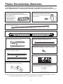
LAS PIEZAS QUE SE DETALLAN A CONTINUACIÓN, SE SUMINSTRAN CON EL HORNO:
NOTA: Dependiendo de sus necesidades de ventilación, puede que no se utilicen todas estas piezas.
Compuerta/conducto de conexión
Una abrazadera del cable de alimentación y
Un tornillo de montaje de color oscuro
(para sujetar el cable de alimentación)
Tamaño Real
Dos tornillos de fiador de 1/4" x 3" - Tamaño
Real (para orificios de paneles de yeso)
Un esquema del armario superior- No es el
Tamaño Real
Un esquema de la pared trasera- No es el
Tamaño Rea (1 única placa de sujeción)
Un casquillo de la abrazadera del cable de alimentación
Una placa de sujeción - No es el Tamaño Real (para el apoyo del horno microondas )
- Tamaño Real (para el orificio del cable en un
armario superior metálico)
NOTA: Es necesario instalar al menos un tirafondo en un taco de 2 "x 4" y tres pernos de anclaje en la pared.
y la zona de montaje deberá cumplir con el requisito de peso de 150 libras.
Dos tornillos de fiador de 1/4" x 2"- Tamaño Real
(para orificios de paneles de yeso)
Dos tornillos de 1/4" x 3" - Tamaño Real (para
asegurar el armario superior)
Dos tornillos de 1/4" x 3" - Tamaño Real
(para asegurar el armario superior)
Dos tornillos de rosca - Tamaño Real (para la
sujeción de la compuerta/conducto de conexión)
WARNING - TO REDUCE THE RISK OF FIRE AND ELECTRIC SHOCK,
INSTALL AT LEAST 13-3/4 INCHES ABOVE A COOKTOP(OR RANGE)
SUITABLE FOR USE ABOVE GAS OR ELECTRIC
COOKING EQUIPMENT 36 INCHES OR LESS WIDE.
APTO PARA SU USO SOBRE EQUIPOS ELÉCTRICOS O
A GAS CON ANCHO DE 36 PULGADAS (90CM) O INFERIOR
ADVERTENCIA - PARA REDUCIR EL RIESGO DE INCENDIO Y DE DESCARGA ELÉCTRICA,
INSTALE AL MENOS A 13-3/4 PULGADAS (35CM) SOBRE LA VITROCERÁMICA (O FOGÓN)
(para instalación de ventilación de techo o
ventilación de pared) No es el Tamaño Real (las 2
piezas deberán ser
montados tal como se
muestra) No utilizar en
caso de salida de
humos hacia la cocina.
- 4 -

Piezas, Herramientas, Materiales
Cinta transparente
(para encintar esquemas a la pared)
Destornillador Phillips
(para tornillos)
Guantes
Lapiz
Destornillador plano
(para tornillos de fiador)
Plomada
Cinta métrica
(mejor metálica)
Cinta para conductos
pistola de masilla y masilla
Localizador de Montante
sierra de sable
(para cortar los orificios de
ventilación para techo o
ventilación de pared)
Sierra de punta (para orificio de cable de alimentación)
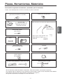
Necesitará las siguientes herramientas y materiales para la instalación:
Cartón u otro material pesado, tal como una manta para cubrir la encimera.
Brocas para madera de 3/8"y 3/4"
Brocas de 1/2" y 3/16"
Plomada
Taladro eléctrico
cortadora lateral pequeña o tijera para metal
s%NCASODETENERPAREDESDELADRILLOOMAMPOSTERÓANECESITARÈHARDWAREYHERRAMIENTASESPECIALES
s,OSCONDUCTOSQUESENECESITANPARALAINSTALACIØNNOESTÈINCLUIDOS4ODASLASTAPASDEPAREDYTECHODEBERÈN
tener registros de tiro traseros para compuerta (mostrados en la página 4).
s5SEGUANTESAPROPIADOSPARAPROTEGERSUSMANOSDELESIONES
- 5 -
ESPAÑOLESPAÑOL

PASO 1: Preparar la conexión eléctrica
Una conexión a tierra incorrecta podría provocar descargas eléctricas,
incendios u otros daños personales.
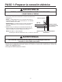
1.Colocar la toma de corriente eléctrica para conexión a tierra de este
horno en el armario encima del horno, tal como se muestra en la
Ilustración 5.
NOTA: La salida deberá estar en una circuito único para el
microondas (120V, 60 Hz., AC únicamente) con 15 o 20A de
suministro eléctrico con fusible.
IMPORTANTE: En caso de no tener una toma de corriente
adecuada, DEBE tener una instalado por un electricista
autorizado.
2. Deberá hacer un orificio para el cable de alimentación (tal
como se muestra en la Ilustración 5) más tarde cuando se
prepara la pared y el armario superior en el Paso 4.
NOTA: No utilice un cable alargador.
Mantenga el cable de alimentación seco y no dañar o aplastarlo.
s.5.#!"!*/.).'5.!#)2#5.34!.#)!2%4)2!2,!#,!6)*!$%#/.%8)».!4)%22!$%,
#!",%$%!,)-%.4!#)».
s%STEAPARATO$%"%CONECTARSEATIERRA
EVITAR LA DESCARGA ELECTRICA! ESTE APARATO DEBE
CONECTARSE A TIERRA!
Armario superior
Orificio para el cable de alimentación
Ilustración 5
Toma de corriente
con conexión a tierra
(armario interior)
ADVERTENCIA
ADVERTENCIA
- 6 -

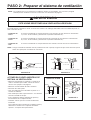
PASO 2: Preparar el sistema de ventilación
ESTE HORNE DEBE TENER UNA VENTILACIÓN APROPIADA!
NOTA: Los conductos que se necesitan para la ventilación exterior no está incluidos. Los accesorios y longitud
estándar para los conductos accesorios se muestran en la Ilustración 10, página 8.
Es posible aportar ventilación su horno en una de tres maneras. Sin embargo, NO ventilar hacia una cavidad de pared, un
ático o una zona sin uso.
Ventilación de
Techo
Si el horno está ubicado en una pared exterior cerca del techo, tal como muestra en la Ilustración
7 (3 1/4 "x 10" de conducto) y la Ilustración 9 (conducto redondo de 6".)
Ventilación de
Pared
Si el horno está ubicado en una pared exterior de la vivienda, tal como muestra en la Ilustración
6 (3 1/4 "x 10" de conducto) y la Ilustración 9 (conducto redondo de 6".)
Ventilación de
Sala
Si el horno está ubicado en una pared interior de la vivienda, tal como muestra en la Ilustración 8.
NOTA: Si elige el método de ventilación trasera (ventilación de techo o pared), asegúrese de que existe suficiente espacio
dentro de la pared para el conducto de evacuación.
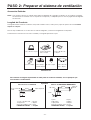
A TENER EN CUENTA MIENTRAS SE
INSTALA LA VENTILACIÓN:
Armario
Horno
Fijación de pared
A través del conducto de pared
Tapa de Pared
Conducto
3 1/4" x 10"
Armario
Horno
Ilustración 6
Ventilación de Pared
A través del conducto de techo
Conducto
3 1/4" x 10"
Tapa de Techo
Techo Ventilación
Armario
Horno
Ilustración 7
Ventilación de Techo
Ilustración 8
Ventilación en Sala
Conducto
Redondo de 6”
de diámetro
mínimo
Conducto
Redondo de
Paso de
3 1/4"
Tapa de Techo
Tapa de
Pared
Codo
Ilustración 9
ADVERTENCIA
s-ANTENERLALONGITUDDELOSCONDUCTOSYELNÞMERODE
codos a un mínimo para ventilar el horno de manera
eficiente. Ver ejemplos en la página 8.
s-ANTENERELMISMOTAMA×ODETODOSCONDUCTOS
s.OINSTALEDOSCODOSJUNTOS
s5SARCINTAADHESIVAPARASELLARTODASLASJUNTASENEL
sistema de conductos.
s5SARMASILLAPARASELLARLAPAREDEXTERIOROENLAABERTURA
del techo alrededor de la tapa.
s4RASLAINSTALACIØNDEBERÈCOMPROBARLAAPERTURAY
funcionamiento de la campana exterior.
s!LINSTALARELHORNOPORFAVORCONSULTEEL-ANUALDE
instalación.
Para la ubicación de la apertura de la campana exterior y
dimensiones consultar con el esquema del armario
superior o el esquema de la pared trasera.
- 7 -
ESPAÑOLESPAÑOL

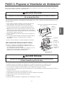
PASO 2: Preparar el sistema de ventilación
Accesorios Estándar
NOTA: Si el conducto existente es redondo, debe utilizar un adaptador de rectangular a redondo, con un conducto rectangular
de extensión de 3" instalado entre el conjunto de la compuerta y el adaptador para así evitar el pegado del amortiguador
de extracción.
Longitud del Conducto
La longitud total del sistema de conductos, incluyendo conductos rectos, codos, pasos y tapas de pared o de techo no deben
superar los 140 pies.
Para un mejor rendimiento, no use más de tres codos de 90 grados, y mantener la longitud más corta posible.
A continuación se muestran los accesorios estándar y su longitud equivalente en pies.
Para calcular la longitud equivalente de cada parte de conducto utilizado, ver los ejemplos que
se muestran a continuación.
Ilustración 10
6 pies
3 1/4" x 10" 90°
codo
1 3 1/4" x 10" 90° codo = 25 pies
1 tapa pared = 40 pies
8 pies de conducto recto = 8 pies
2 pies
2 pies
Tapa de pared
6 pies
90° codo
Paso
Tapa de
pared
Para 3 1/4" x 10 sistemas
LONGITUD TOTAL = 73 pies
1 paso = 5 pies
2 90º codos = 20 pies
1 tapa pared = 40 pies
8 pies de conducto recto = 8 pies
LONGITUD TOTAL = 73 pies
Para 6" de SISTEMAS REDONDOS
3 1/4" x 10" a 6" = 5 pies
90˚ codo = 10 pies
3 1/4" x 10"tapa
de pared = 40 pies
45˚ codo = 5 pies 3 1/4" x 10" codo
plano = 10 pies
3 1/4" x 10" tapa de
techo = 24 pies
3 1/4"x 10" 90˚ codo
= 25 pies
1 2 3
4 5 6 7
Ejemplos
- 8 -

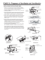
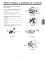
PASO 3: Preparar el Ventilador de Ventilación
Su horno microondas se suministra con ventilador montado para ventilación de techo. Será necesario ajustar el ventilador si
desea instalar ventilación de pared o ventilación de sala.
s./4)2!2$%/%34)2!2%,#!",%!$/$%,6%.4),!$/24IRARYESTIRARELCABLEADODELVENTILADORPODRÓAPROVOCARUNA
descarga eléctrica.
INSTALACIÓN DE VENTILACIÓN DE TECHO:
Ilustración 11
PELIGRO DE DESCARGA ELÉCTRICA! DESENCHUFAR EL APARATO ANTES
DE SU MANIPULACIÓN.
RIESGO DE INCENDIO! INSTALAR EL VENTILADOR DE VENTILACIÓN
CORRECTAMENTE ANTES DE USAR .
ADVERTENCIA
ADVERTENCIA
Ilustración 12
.OTA#OLOCARELPRODUCTOSOBREUNASUPERFICIE
plana únicamente
#UBIERTA
protectora
gruesa
#OMPUERTA
!DAPTADOR
de extracción
Placa de
6ENTILADOR
4RASERADEL
Horno
2ETIRECUALQUIERMATERIALDEEMBALAJEYLASPIEZASDELINTERIORDEL
HORNOMICROONDAS#OLOCARAUNLADOPARASUUSOPOSTERIOR
#UBRIRMOSTRADOROVITROCERÈMICACONUNPROTECTORGRUESOPARA
PREVENIRLOSPOSIBLESDA×OSPORSUCIEDAD#ONSULTAR)LUSTRACIØN
NOTA:%NCASODETENERUNFOGØNAUTØNOMODESCONECTARCOLOCAR
SOBREUNTROZODECARTØNOTABLEROYSEPARARLEJOSDELAPAREDPARA
QUEASÓPUEDAESTARMÈSCERCADELARMARIOSUPERIORYLAPAREDTRASERA
PARAFACILITARLAMEDICIØNYPERFORACIØN
#OLOCARELADAPTADORDEEXTRACCIØNFILTROSDEGRASAYELPAQUETEDE
herramientas.
%NESTEPUNTOELIMINARCUALQUIERCINTAADHESIVASIHUBIESEALGUNA
ENELADAPTADOREXTRACCIØNLOSFILTROSDEGRASAYELCABLEDE
alimentación.
s.ORETIRELACINTADEEMBALAJEENLAREJILLADESLIZABLEDEVENTILACIØN
%STEHORNOSESUMINISTRAYAMONTADOPARAVENTILACIØNDETECHO
)NSERTARLASLENGàETASDECADALADODELACOMPUERTAENLOSORIFICIOS
en la parte trasera interior del adaptador.
Fijar el adaptador de extracción a la placa del ventilador con los dos
TORNILLOSDEROSCASUMINISTRADOS#ONSULTAR)LUSTRACIØN
!SEGÞRESEDEQUELACOMPUERTAOSCILALIBREMENTE
s!LCAMBIARLAPOSICIØNDELVENTILADORDEVENTILACIØNPORUNAVENTILACIØNDEPAREDTRASERAOVENTILACIØNDESALA
!LINEARCORRECTAMENTELASABERTURASDELVENTILADORDEVENTILACIØNYLOSTROQUELESDELAPLACADELVENTILADOR
,ASABERTURASDELVENTILADORDEVENTILACIØNDEBERÈNESTARCOMPLETAMENTEEXPUESTASALEXTERIOR
4RASLAINSTALACIØNCOMPROBARLATRAYECTORIADEVENTILACIØNDEAIRE#ONSULTARPÈGINA)LUSTRACIONESPARALASELECCIØNDE
ventilación adecuada.
s,AINSTALACIØNINCORRECTAPUEDECAUSARPROBLEMASTALESCOMO
)NCAPACIDADPARAMONTARLAPLACADELVENTILADOROELMOTORDEVENTILACIØNCORRECTAMENTE
2UIDOSEXTRA×OSDURANTEELFUNCIONAMIENTODELPRODUCTO
6ENTILACIØNDÏBIL
3OBRECALENTAMIENTODELPRODUCTOPOSIBILIDADDEAVERÓADELPRODUCTOOINCENDIO
- 9 -
ESPAÑOLESPAÑOL

PASO 3: Preparar el Ventilador de Ventilación
INSTALACIÓN DE VENTILACIÓN DE PARED:
Ilustración 13
Placa de Ventilador
Tornillo de fijación
Placa de Ventilador
Placa trasera
Unidad de Ventilador
Tornillo de fijación
Unidad de
Ventilador
Pieza B
Ilustración 14
Unidad de
Ventilador
Puertos de Extracción
Ilustración 15
Ilustración 16
Ilustración 18
Placa de Ventilador
Tornillo de Fijación
Placa de Ventilador
Placa Trasera
Unidad de Ventilador
Puertos de Exracción
Unidad de
Ventilador
Unidad de Ventilación
Tornillo de Fijación
Ilustración 17
Puertos de Extracción
Adaptador de
Extracción
Compuerta
(bisagra hacia arriba)
Deslizar el
adaptador de
extracción en
la guías en el
panel trasero
Guías
Ilustración 19
Piezas B
Troqueles B
Ilustración 20
1. Quitar uno o dos tornillo(s) de montaje de unidad del ventilador y
uno o varios tornillo(s) de placa de sujeción del ventilador. Retirar la
placa del ventilador del armario. Consultar Ilustración 13.
2. Levantar con cuidado la unidad del ventilador del horno microondas.
Consultar Ilustración 14.
3. Usar cortadoras laterales o tijeras para metal u hojalata para cortar y
retirar los troqueles B de la placa Trasera. Desechar los troqueles.
Tenga cuidado de no deformar la placa. Consultar Ilustración 15.
4. Volver a montar el cable del ventilador. Consultar Ilustración 16.
5. Girar y volver a instalar la unidad del ventilador de nuevo de manera
que los puertos de extracción quedan frente a la parte trasera del
armario y se alinean con los recortes traseros. Consultar Ilustra-
ciones 17 & 18.
6. Fijar nuevamente la placa del ventilador al horno microondas de
modo que los puertos de extracción y la apertura de la placa del
ventilador están alineados. Fijar con un tornillo de montaje de la
unidad del ventilador y a continuación uno o varios tornillos de placa
de sujeción del ventilador(3).Consultar Ilustración 19.
7. Insertar las lengüetas de cada lado de la compuerta en los orificios
en la parte trasera interior del adaptador.
Fijar el adaptador de extracción a la placa trasera de pared lateral.
Presione firmemente hasta que esté más allá de las lengüetas de
fijación superiores y las lengüetas de fijación inferiores. Asegurarse
que la bisagra de la compuerta está instalada de manera que queda
en la parte superior y que la compuerta oscila libremente. Consultar
Ilustración 20.
Lengüetas
de bloqueo
- 10 -

PASO 3: Preparar el Ventilador de Ventilación
VENTILACION DE SALA (Recirculación)
INSTALACIÓN:
Ilustración 21
Placa de Ventilador
Tornillo de Fijación
Placa de Ventilador
Placa Trasera
Pieza B
Unidad de
Ventilador
Ilustración 23
Unidad de Ventilador
Unidad de Ventilación
Tornillo de Fijación
Placa de Ventilador
Tornillo de Fijación
Placa de Ventilador
Placa Trasera
Unidad de Ventilación
Tornillo de Fijación
Unidad de
Ventilació
Pieza B
Ilustración 24
Ilustración 25
Ilustración 22
1. Quitar uno o dos tornillo(s) de montaje de unidad del
ventilador y uno o varios tornillo(s) de placa de sujeción del
ventilador. Retirar la placa del ventilador. Consultar
Ilustración 21.
2. Levantar con cuidado la unidad del ventilador del horno
microondas. Consultar Ilustración 14.
3. Volver a montar el cable del ventilador. Consultar Ilustración
22.
4. Girar la unidad del ventilador 90° para que los puertos de
extracción queden en del frente del armario. Consultar
Ilustración 23.
5. Colocar la unidad del ventilador nuevamente en el horno
microondas.
Asegurarse de que los cables no están dañados. Consultar
Ilustración 24.
6. Fijar nuevamente la placa del ventilador al horno
microondas.
Fijar con un tornillo de montaje de la unidad del ventilador y a
continuación uno o varios tornillos de placa de sujeción del
ventilador. Consultar Ilustración 25.
- 11 -
ESPAÑOLESPAÑOL

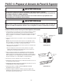
PASO 4: Preparar el Armario de Pared & Superior
Para evitar lesiones o daños personales, no intente instalar este horno microondas si
no puede encontrar un montante. Consulte a un carpintero o contratista.
Medir y Fijar/Cintar los Esquemas
NO INTENTE INSTALAR EL HORNO DE
MICROONDAS SI NO PUEDE ENCONTRAR
UN MONTANTE.
PRECAUCIÓN
Ilustración 26
Ilustración 27
ADVERTENCIA
Esquema de Armario Superior
Placa de Fijación
1. Mediante el uso de una plomada y una cinta de medir (de
metal), encontrar y marcar la línea central vertical en la pared
trasera, como en la Ilustración 26.
2. Encontrar y marcar uno o dos puntos en los que los montantes
estén sobre la pared. (Los montantes están normalmente a 16
pulgadas de distancia). A continuación, medir y marcar las
posiciones de los montantes. Si no puede encontrar ningún
montante, consultar con un contratista local de obras.
3. Dibujar una línea vertical en la pared en el centro de un espacio
de 30" de ancho.
NOTA: Asegúrese de que la anchura mínima es de 30 pulgadas.
4. Centrar el esquema o plantilla de la pared trasera en el espacio
alineando la plomada en la pared con la línea central de la
plantilla. A continuación fijar o encintar firmemente el esquema
de la pared trasera en su sitio. Asegúrese de que la anchura
mínima es de 30 pulgadas y la parte superior del esquema de la
pared trasera queda ubicada a 30 pulgadas mínimo por encima
de la zona de cocción. Consultar Ilustración 26.
NOTA: Si los armarios no están a plomo, ajustar el esquema de
la pared trasera a los armarios. Si el borde frontal del armario es
más bajo que dl borde trasero, ajustar el esquema para estar a
nivel con la parte frontal del armario.
5. Medir la parte inferior del marco del armario superior. Recortar
los bordes A, B, y C en el esquema del armario superior de
modo que el esquema se ajusta en la parte inferior del armario
superior. Si el armario superior tiene un marco empotrado,
recortar el esquema para que se ajuste dentro del área
empotrada. Alinear la línea central del esquema del armario
superior con la línea central del esquema de la pared trasera, a
continuación fijar o encintar firmemente el esquema del armario
superior en su sitio. Consultar Ilustración 27.
- 12 -

PASO 4: Preparar el Armario de Pared & Superior
Perfore Orificios en la Pared y la Parte Superior del Armario
bloque de
relleno
Estanteria inferior
del armario
Armario frontal
Ilustración 28
bloque de
relleno
Ilustración 29
Para evitar el riesgo de lesiones personales, descarga eléctrica o muerte:
• Antes de taladrar en la pared, averiguar donde pueden estar ocultos detrás de la pared los
enchufes eléctricos y cables eléctricos.
• Localizar y desconectar la alimentación de los circuitos eléctricos que podrían verse
afectadas por la instalación de este horno.
Para evitar el riesgo de lesiones personales, descarga eléctrica o muerte, cubrir el borde del
orificio de cable de suministro eléctrico con el casquillo de cable de suministro de energía.
ADVERTENCIA
ADVERTENCIA
1. Perforar orificios en los círculos. En caso de existir un montante, taladrar
un orificio de 3/16" para tirafondos. En caso de existir un montante,
taladrar un orificio de 3/4" para tornillos de fiador. Asegúrese de utilizar al
menos 1 tirafondo en un montante, y 2 tornillos de mariposa en cartón
yeso o el yeso.
2. Perforar un orificio de 3/8" en los puntos J y K en el esquema del armario
superior.
NOTA: Si la parte inferior del armario superior está empotrado a 3/4"o
más, necesitará 2 "x 2" bloques de relleno (no incluidos) para proporcio-
nar apoyo adicional a los pernos. Consultar Ilustración 28.
s-ARCARELCENTRODECADABLOQUEDERELLENOYPERFORARUNORIFICIODE
de diámetro en las marcas.
s!LINEARLOSBLOQUESDERELLENOSOBRELASDOSABERTURASENLAPARTE
superior del armario del horno de microondas y fijar al armario con
cinta adhesiva. Consultar Ilustración 29.
3. Cortar o perforar un agujero de 2" de diámetro en la parte marcada
ORIFICIODELCABLEDELAFUENTEDEALIMENTACIØN-ENELESQUEMADEL
armario superior. Si el armario superior es de metal, necesitará cubrir el
borde del agujero con el casquillo del cable de alimentación (suministra-
do) para evitar daños en el cable debidos a la rebarba metálica.
4. Recortar las áreas de ventilación (con una sierra de sable):
s6ENTILACIØNDE4ECHO2ECORTARLAZONASOMBREADAMARCADACONUNA,EN
el esquema del armario superior.
s6ENTILACIØNDE0ARED2ECORTARLAZONASOMBREADAMARCADACONUNA&EN
EL%315%-!$%0!2!0!2%$42!3%2!
s6ENTILACIØNDE3ALAIRA0!3/).34!,!#)/.$%0,!#!$%
35*%#)».UBICADOENPÈGINA
#OMPLETARCUALQUIERSISTEMADEVENTILACIØNQUEHAYAELEGIDO5SAR
masilla para sellar la pared exterior o en la abertura del techo alrededor
de la tapa de la pared o tapa del techo.
- 13 -
ESPAÑOLESPAÑOL

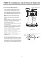
PASO 5: Instalación de la Placa de Sujeción
C
B
A
Conectar el Horno al Menos Un Montante.
Ilustración 31
Ilustración 30
Pared
Placa de
fijación
Final del
perno
3/16"orificios en montantes
5/8"orificios en cartón yeso únicamente
Mínimo 66"
desde el suelo
Para Ventilación
de Pared
únicamente
Líneas de
Dibujo en
Montantes
Línea de
Dibujo en
el Centro
Línea Central
Placa de Fijación
Lengüeta de apoyo
Lengüeta de apoyo
1. Centrar el esquema o plantilla de la pared trasera en el
espacio alineando la plomada en la pared con la línea
central de la plantilla. A continuación fijar o encintar
firmemente el esquema de la pared trasera en su sitio.
Asegúrese de que la anchura mínima es de 30 pulgadas y
la parte superior del esquema de la pared trasera queda
ubicada a 30 pulgadas mínimo por encima de la zona de
cocción. Consultar Ilustración 26.
NOTA: Si los armarios no están a plomo, ajustar el
esquema de la pared trasera a los armarios. Si el borde
frontal del armario es más bajo que dl borde trasero, ajustar
el esquema para estar a nivel con la parte frontal del
armario.
2. Perforar los agujeros en los puntos A, B. Perforar el tercer
agujero dentro de la zona C, a través de uno de los
agujeros inferiores para que coincida con la ubicación de un
montante. En caso de existir un montante, taladrar un
orificio de 3/16" para tirafondos.
En caso de existir un montante, taladrar un orificio de 5/8"
para tornillos de fiador.
Estos agujeros deben ser utilizados para la sujeción. Si no
se utilizan los orificios, la instalación no será segura. El
instalador debe utilizar estos agujeros para la correcta
instalación. Consultar Ilustración 30.
Usar los tornillos de fiador a través de estos orificios, a
menos que uno de ellos este alineado con un montante.
Utilice un tornillo para madera para montantes.
Asegúrese de utilizar al menos 1 tirafondo en un montante,
y 2 tornillos de fiador en cartón yeso o el yeso.
NOTA: Recortar la zona sombreada marcada con una F en
el ESQUEMA DE PARA PARED TRASERA para la
ventilación de pared.
3. Retirar el esquema de la pared trasera.
4. Fijar la placa a la pared. Para utilizar tornillos de arandelas
de resorte: Retirar alas de los tornillos de fiador. Insertar los
tornillos en la placa de sujeción y vuelva a colocar el tornillo
de arandela de resorte de 3/4 pasado el final del perno.
Inserte el tornillo de arandela de resorte en los agujeros de
la pared fijar la placa. Puede tirar hacia adelante en el placa
para ayudar a apretar los tornillos de fiador. Apretar todos
los tornillos. Consultar Ilustración 31.
Más espacio que el grosor de la pared
alas de los tornillos de fiador 1
Tornillo
de fiador
- 14 -

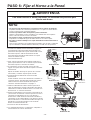
PASO 6: Fijar el Horno a la Pared.
Ilustración 32
Ilustración 33 Ilustración 35
Ilustración 36
Ilustración 34
Cable de
alimentación
Orificio para el
cable de
alimentación
Para evitar lesiones o daños personales, se necesitan dos personas para
instalar este horno.
ADVERTENCIA
Compuerta
Abrazadera
del cable de
alimentación
NOTA:
1
2
3
1
2
1RHMHUFHUIXHU]DGLUHFWDPHQWHDODVXSHUILFLHLQIHULRUH[WHULRUGHOSURGXFWR
El pestillo deslizable de ventilación puede dañarse si se aplica una fuerza directa-
mente a la parte inferior central del producto.
&RORFDUHOSURGXFWRVREUHXQDVXSHUILFLHSODQD~QLFDPHQWH
Durante el desembalaje, colocar el producto con cuidado sobre una superficie
plana, como una mesa de cocina o mostrador.
1ROHYDQWDURFDUJDUHOSURGXFWRSRUODVXSHUILFLHLQIHULRUFHQWUDO
El producto se manipula mejor por los lados inferiores cerca de las patas.
1RUHWLUHODFLQWDGHHPEDODMHHQODUHMLOODGHVOL]DEOHGHYHQWLODFLyQGXUDQWHOD
LQVWDODFLyQ
Una vez que el producto esté completamente instalado, retire la cinta y comprobar
que la ventilación se desliza fácilmente abriendo y cerrando con sólo presionar.
1. Levantar con cuidado el horno microondas y colgarlo en
las lengüetas de apoyo (Consultar Ilustración 30) en la
parte inferior de la placa de sujeción. Alcanzando a través
del armario superior, cable de alimentación del hilo
través del orificio del cable de alimentación en la parte
inferior del armario superior.
Consultar Ilustración 32.
2. Girar el horno microondas hacia arriba de modo que la
parte superior del horno está en contra de la parte inferior
del armario superior o del marco del armario.
3. A continuación, insertar un tornillo a través de cada
agujero en la parte inferior del armario superior. Consultar
Ilustración 33.
Apretar los tornillos hasta que el espacio entre el horno
microondas y el armario superior quede cerrado.
4. Instalación de la Ventilación de Techo: Consultar
Ilustración 34.
Instalar conducto a través de la abertura de ventilación en
el armario superior. Usar pistola de masilla para sellar la
abertura del techo exterior alrededor de la tapa de
extracción. Consultar Ilustración 7 en página 7.
5. Utilizar la abrazadera de cables eléctricos para atar el
cable de alimentación. Instalar la abrazadera del cable de
alimentación, usando un tornillo tal como se muestra en la
Ilustración 35, en el interior del armario.
6. Agarrar la malla filtrante con una mano sosteniendo el aro
y la otra mano sosteniendo el extremo opuesto. Insertar el
extremo de la malla filtrante sin aro en la abertura y
deslizar hacia el lado del horno microondas. Introducir el
extremo del aro de la malla filtrante en la abertura y deslice
toda la malla hacia el centro del microondas hasta que esté
firmemente en su posición. Repita con la otra malla
filtrante. Consultar Ilustración 36.
7. Conectar el cable de alimentación.
8. Lee el Manual del Usuario, a continuación, comprobar el
funcionamiento de su horno microondas.
- 15 -
ESPAÑOLESPAÑOL

.HQPRUH
§
)RU6HDUV+RPH6HUYLFHVLQKRPHUHSDLU
RIDOO.HQPRUHPDMRUDSSOLDQFHV
)RUWKHUHSODFHPHQWSDUWVDFFHVVRULHVDQG
8VH&DUH*XLGHVWKDW\RXQHHGWRGRLW\RXUVHOI
)RUSURIHVVLRQDOLQVWDOODWLRQRIPDMRUKRPHDSSOLDQFHV
DQGLWHPVOLNHDLUFRQGLWLRQHUVDQGZDWHUKHDWHUV
ZZZNHQPRUHFRP
,Q&DQDGD
,Q&DQDGD,Q&DQDGD
,Q&DQDGD
ZZZVHDUVFD
&DOODQ\WLPHIRUWKHORFDWLRQRI\RXUQHDUHVW
6HDUV
6HDUV6HDUV
6HDUV
3DUWV5HSDLU6HUYLFH&HQWHU
3DUWV5HSDLU6HUYLFH&HQWHU3DUWV5HSDLU6HUYLFH&HQWHU
3DUWV5HSDLU6HUYLFH&HQWHU
86$
&DQDGD
7RSXUFKDVHDSURWHFWLRQDJUHHPHQWRQDVHUYLFHDEOHSURGXFW
86$
&DQDGD
3DUDSHGLUVHUYLFLRGHUHSDUDFLÚQ
DGRPLFLOLR\RUGHQDUSLH]DV
68
6868
68
+2*$5
+2*$5+2*$5
+2*$5
§
ZZZNHQPRUHFRP
$X&DQDGDSRXUVHUYLFHHQIUDQÐDLV
/(
/(/(
/(
)2<(5
)2<(5)2<(5
)2<(5
0&
ZZZVHDUVFD
-
 1
1
-
 2
2
-
 3
3
-
 4
4
-
 5
5
-
 6
6
-
 7
7
-
 8
8
-
 9
9
-
 10
10
-
 11
11
-
 12
12
-
 13
13
-
 14
14
-
 15
15
-
 16
16
-
 17
17
-
 18
18
-
 19
19
-
 20
20
-
 21
21
-
 22
22
-
 23
23
-
 24
24
-
 25
25
-
 26
26
-
 27
27
-
 28
28
-
 29
29
-
 30
30


Kenmore Elite 72187583610 Guía de instalación
- Categoría
- Microondas
- Tipo
- Guía de instalación
- Este manual también es adecuado para
en otros idiomas
Artículos relacionados
Otros documentos
-
Maytag MMV6178 Installation Instructions Manual
-
Kenmore 72162644200 Guía de instalación
-
-
IKEA IMH172DS1 Guía de instalación
-
-
Haier HMV1630HBSA Manual de usuario
-
GE CVM521P2MS1 Guía de instalación
-
GE 1067756 Guía de instalación
-
-
Jenn-Air AMV4204AAW Guía de instalación