Bosch HMV3061U/01 Guía de instalación
- Categoría
- Microondas
- Tipo
- Guía de instalación
Este manual también es adecuado para

Microwave oven
Model:
HMV 3051 U
HMV 3061 U
HMV 3021 U
BOSCH

Table of Contents
Safety ........................................ 4
Important Safety Instructions ...................................... 4
Before you begin ................................................. 7
Location requirements .............................................. 9
Installation procedure ............................................. 10
Removing the mounting plate ........................................ 10
Finding the wall studs ............................................... 10
Possible wall stud configurations ...................................... 10
Attaching the mounting plate to the wall ................................ 12
Installation types ................................................... 16
Roof venting ....................................................... 17
Wall venting ....................................................... 20
Room venting ..................................................... 25
Mounting the microwave oven ........................................ 27
Hood exhaust ..................................................... 29
Service .......................................................... 30
3

Safety
Important Safety Instructions
READ AND SAVE THESE INSTRUCTIONS
Impo_ant
Examine your oven
Appliance handling safety
Intended Use
Grounding Instructions
SAVE THESE INSTRUCTIONS FOR THE LOCAL ELECTRICAL INSPECTOR'S USE.
LEAVE THESE INSTRUCTIONS WITH THE APPLIANCE AFTER INSTALLATION IS
COMPLETE.
_ ARNING: Ifthe information in this manual is not followed exactly, fire or
shock my result causing property damage or personal injury.
Unpack oven, remove all tape and packaging material and examine the oven for any
damage such as dents, broken door latches or cracks in the door. Notify dealer
immediately if oven is damaged. Do not install if oven is damaged.
Destroy the packaging after unpacking the appliance. Never allow children to play
with packaging material.
Unit is heavy and requires at least two people or proper equipment to move.
Hidden surface may have sharp edges. Use caution when reaching behind or under
appliance.
_ AUTION: For general ventilating use only. Do not use to exhausthazardous or explosive materials and vapours.
This appliance must be properly grounded. Grounding reduces risk of electric shock
by providing an escape wire for the electric current if an electrical short occurs. This
oven is equipped with a cord having a grounding wire with a grounding plug. The
plug must be plugged into an outlet that is properly installed and grounded.
_ ARNING: Improper use of the grounding can result in a risk of electric
shock.
Consult a qualified electrician or servicer if grounding instructions are not completely
understood, or if doubt exists as to whether the oven is properly grounded.
Do not use an extension cord. If the product power cord is too short, have a
qualified electrician install a three-slot receptacle. This oven should be plugged into
a separate 60 Hertz circuit with the electrical rating as shown in specifications table.
When the oven is on a circuit with other equipment, an increase in cooking times
may be required and fuses can be blown.
Microwave operates on standard household current, 110-120 V.
4

Important Safety Instructions
READ AND SAVE THESE INSTRUCTIONS
Electrical Requirements ÷ a three prong grounded outlet
÷ 120 V, 60 Hz, AC only
÷ 15 Amp electrical supply with a fuse or a circiut breaker
÷ 1.6 kilowatt
This product must be connected to a supply circiut of the proper voltage and
frequency. Wire size must conform to the requirements of the National Electric Code
or the prevailing local code for this rating. The power supply cord and plug should
be brought to a separate 15- to 20-amp branch circiut single grounded outlet. The
outlet box should be located in the cabinet above the microwave oven. The outlet
box and supply circiut should be installed by a qualified electrician and conform to
the National Electrical Code or the prevailing local code.
The voltage used must be the same as specified on this microwave oven. Using a
higher voltage is dangerous and may result in a fire or oven damage. Using a lower
voltage will cause slow cooking. The dealer is not responsible for any damages
resulting from the use of the oven with any voltage other than specified.
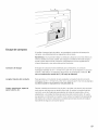
Location requirements Check the opening where the microwave oven will be installed. The location must
provide:
÷ Minimum installation dimensions (See Installation Dimensions illustration)
÷ Minimum one 2" x 4" (50.8 x 101.6 mm) wood wall stud and minimum 3/8" (9.5
mm) thickness drywall or plaster/lath within cabinet opening.
÷ Support for weight of 150 Ibs (68 kg), which includes microwave oven and items
placed inside the microwave oven and upper cabinet.
÷ Grounded electrical outlet inside upper cabinet. (See Electrical Requirements)
section.
Notes:
If installing the microwave oven near a left sidewall, make sure there is at least 7"
(178 mm) of clearance between the wall and the microwave oven, so that the
door can open fully.
Some cabinet and building materials are not designed to withstand the heat
produced by the microwave oven for cooking. Check with your builder or cabinet
supplier to make sure that the materials used will not discolor, delaminate or
sustain other damages.
Ground continuity check The installer must perform a ground continuity check on the power outlet box before
beginning the installation to insure that the outlet box is properly grounded. If not
properly grounded, or ifthe outlet box does not meet Electrical Requirements, a
qualified electrician should be employed to correct any deficiencies.
5

Important Safety Instructions
READ AND SAVE THESE INSTRUCTIONS
Electric safety
Related equipment safety
Service and Repair Safety
_ AUTION: For personal safety, remove house fuse or switch off the circuitbreaker in the fuse box before beginning installation to avoid severe or fatal
shock injury. Lock circuit breaker to prevent power from being turned on
accidently.
Be sure your appliance is properly installed and grounded by a qualified technician.
Installer show the owner the location of the circuit breaker or fuse. Mark it for easy
reference.
Do not, under any circumstances, cut or remove the ground prong.It must be
plugged into a matching grounding type receptacle to aviod electrical shock. Ifthere
is any doubt as to wether the wall receptacle is properly grounded, the customer
should have it checked by a qualified electrician. Do not use an extension cord.
_ CAUTION: For personal safety, this product cannot be installed in cabinetarrangements such as an island or a peninsula. It must be mounted to both
a top cabinet and a wall.
_ WARNING: To reduce the risk of fire, use only metal ductwork.
_ ARNING: Do not repair or replace any part of the appliance unlessspecifically recommended in the manuals. Never modify or alter the
construction of the appliance. Improper installation, service or maintenance
can cause injury or property damage. Refer to this manual for guidance.
Refer all other servicing to a factory authorized service center.

Before you begin
Tools and parts needed
÷ No.1 Phillips screwdriver
÷ Pencil
÷ Ruler ortape measure and straight edge
÷ Drill with 3/16" (5mm),l/2 '' (13 mm) and 5/8" (16 mm) drill bits
÷ Gloves
÷ Saw (saber, hole or keyhole)
÷ Stud finder or hammer
÷ Safety goggles
÷ Level
÷ Duct and masking tape
optional
÷ Carpenter square
÷ Tin snips (to cut damper)
÷ Scissors (to cut top cabinet template)
÷ Filler blocks or scrap wood pieces (for recessed bottom cabinet installations)
7

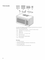
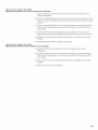
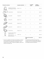
Parts included
A
%
E
B C D
You will find the installation hardware contained in packet with the unit. Check to
make sure you have all these parts:
÷ A Self-Aligning Machine Screws 1A"-28x 31A'' (6-0,9 x 83 mm)
÷ B Toggle bolts 3/16" x 3" (5 x 76 mm)
÷ C Toggle wings
÷ D Wood screws _A"x 2" (6 x 51 mm)
÷ E Power chord strap
÷ F Nylon grommet (for metal cabinets)
÷ G Exhaust adaptor
Not shown:
÷ Top cabinet template
÷ Mounting plate (attached to the back of microwave oven)
÷ Aluminum grease filters
÷ Charcoal filter (attached to microwave oven)

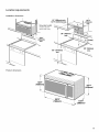
Location requirements
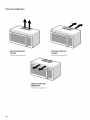
Installation dimensions
12" (305mm) min.
127/8" (327mm) max.
\
Grounded outlet
(Inside cabinet
above the oven)
I
161/2"
min.
(349mm)
min.
2" (51 mm)
66" (1676mm)min.
30" (762mm)
min.
Product dimensions
153/4"
(400mm)
L
297/8"
I 153/8"
(760mm) _(390mm)
161/2"
419mm)
9

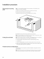
Installation procedure
Removing the mounting
plate
Note: To avoid possible damage to the work surface or to the bottom of the
appliance, cover the worksurface.
1. Remove any remaining contents from the microwave oven cavity.
2. Remove the screws from the mounting plate.
This plate will be used as the rear wall template and for mounting.
Finding the wall studs
3. Reinstall the screws into the holes where they were removed.
Note: To avoid damage to the microwave oven, do not grip or use the door or door
handle while the microwave oven is being handled.
Note: The microwave must be connected to at least one wall stud. If no wall studs
exist within the cabinet opening, do not install the microwave oven.
1. Locate the edges of the wall studs within the cabinet opening by using:
÷ a stud finder or
÷ a hammer (tapping lightly across the mounting surface to find a solid sound).
2. Place a mark halfway between the edges and draw a line down the center of the
studs (See possible wall studs configuration)
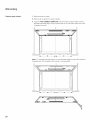
Possible wall stud configurations
These depictions show examples of preferred installation configurations with the
mounting plate.
Note: Care must be taken when drilling holes. Electrical wires may be concealed
behind the wall covering and contact with them could result in electrical shock.
10

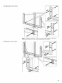
No wall studs at corner holes
Wall stud at one corner hole
Note: If wall stud is within 61A"(159 mm) of the vertical centerline, only Room
Venting (recirculation) or Roof Venting installations can be done.
11

Wall studs at both corner holes
I
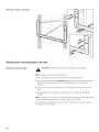
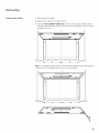
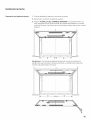
Attaching the mounting plate to the wall
Aligning the mounting plate
_ CAUTION: Wear gloves to avoid cutting fingers on sharp edges.
Note: Make sure the cabinet bottom is level.
1. Draw a vertical line on the wall at the center of the cabinet space.
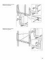
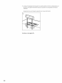
2. Use the mounting plate as a template and place it on the wall, making sure that
the tabs are touching the bottom of the cabinet (Figure 1) or the level line
(Figure 2).
3. Line up the notch and centerline of the mounting plate to the centerline on the
wall.
4. While holding the mounting plate, draw circles on the wall at holes A, B, C
and D.
Note: If neither A, B, C nor D is in a stud, find a stud somewhere in the bottom area
of the mounting plate and draw a fith circle to line up with the stud.
It is important to use at least one wood screw mounted firmly in a stud to support
the weight of the microwave.
12

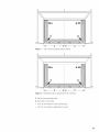
D
-i
i
Figure 1 Flat or frame recessed bottom cabinet
m
m y
D
_ m m _
_ m m y
Figure 2 Recessed bottom cabinet with front overhang
5. Set the mounting plate aside
6. Drill holes on the circles:
÷ 3/16" (5 mm) holes for wood screws (stud)
÷ 5/8" (16 mm) holes for toggle bolts (no stud)
13

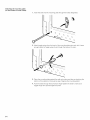
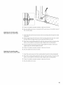
Attaching the mounting plate
(no wall studs at corner holes)
1. Insert the bolts into the mounting plate through the holes designated.
2. Attach toggle wings from the back of the mounting plate onto each bolt. Leave
enough space for toggle wings to go through the wall and to open.
3. Place the mounting plate against the wall and make sure tabs are touching the
bottom of the cabinet or the level line (see "Aligning the mounting plate").
4. Push the bolts through the drywall and finger tighten the bolts to make sure
toggle wings have opened against drywall.
14

Attaching the mounting plate
(Wall stud at one corner hole)
Attaching the mounting plate
(Wall studs at both corner holes)
,41
_J
5. Check if the plate is properly centered, make sure it is level.
6. Securely tighten all screws, including the fifth wood screw in the bottom area of
the mounting plate.
1. Insert the bolts and the wood screws into the mounting plate through the holes
designated.
2. Attach toggle wings from the back of the mounting plate onto each bolt. Leave
enough space for toggle wings to go through the wall and to open.
3. Place the mounting plate against the wall and make sure tabs are touching the
bottom of the cabinet or the level line (see "Aligning the mounting plate").
4. Push the bolts through the drywall and finger tighten the bolts to make sure
toggle wings have opened against drywall.
5. Check if the plate is properly centered, make sure it is level.
6. Securely tighten all screws and bolts.
1. Insert the wood screws into the mounting plate through the holes designated.
2. Place the mounting plate against the wall and make sure tabs are touching the
bottom of the cabinet or the level line (see "Aligning the mounting plate").
3. Check if the plate is properly centered, make sure it is level.
4. Securely tighten all screws.
15

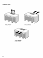
Installation types
ROOF VENTING
proceed to page 17
WALL VENTING
proceed to page 20
ROOM VENTING
proceed to page 25
16

Roof venting
Prepare upper cabinet 1. Remove power to outlet.
2. Remove all contents from upper cabinet.
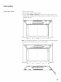
3. Tape the TOP CABINET TEMPLATE onto the bottom surface. Make sure the
template centerline aligns with the vertical line on the wall. Rear wall arrows must
be against rear wall.
i
i
I
i
i
I
I
I
I
I
i
i
i
I
ooooooooooooloOOOOOOOOOOO
L ooooooooooo ooooooooooo
I
Note: For recessed cabinet bottom, trim the template edges so that it fits inside the
recessed area. The template has trim lines to use as guides.
©
i
i
i
i
i
i ilc
ooooooooooooloooooooooooo il(
ooooooooooo,i, ooooooooooo _
17

4. Drill %" (9,5 mm) holes at "A", "B" and "C"
_ CAUTION: Wear safety goggles when drilling holes in the cabinet bottom.
5. Cut out the 2" (50,8 mm) hole at "D". This hole is for the power supply cord.
Note: If the cabinet is metal, use the nylon grommet around the opening to protect
the cord.
6. Cut out the shaded area "E" using a saber or keyhole saw.
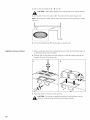
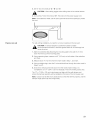
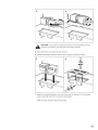
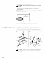
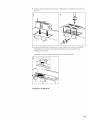
Adapting microwave blower 1. Remove and save the screws holding the blower motor and the blower plate. Lift
up the blower plate and put it aside.
2. Carefully pull out the blower unit and rotate 90° so that fan blade openings are
facing out the top of the microwave
3. Place the blower unit back into the opening.
_ AUTION: Do not pull or stretch the blower unit wiring. Make sure thewires are not pinched, and that they are properly secured.
18

4. Replace the blower plate and secure with the srews removed in step 1.
3. 4.
5. Attach the exhaust adapter to the top of the blower plate by sliding it into the
guides. Push in securely until it is in the locking tabs.
Make sure the damper hinge swings freely.
Proceed on page 27.
19

Wall venting
Prepare upper cabinet 1. Remove power to outlet.
2. Remove all contents from upper cabinet.
3. Tape the TOP CABINET TEMPLATE onto the bottom surface. Make sure the
template centerline aligns with the vertical line on the wall. Rear wall arrows must
be against rear wall.
i
i
I
i
i
I
I
I
I
I
i
i
i
I
ooooooooooooloOOOOOOOOOOO
L ooooooooooo ooooooooooo
I
Note: For recessed cabinet bottom, trim the template edges so that it fits inside the
recessed area. The template has trim lines to use as guides.
©
i
i
i
i
i
i ilc
ooooooooooooloooooooooooo il(
ooooooooooo,i, ooooooooooo _
2O

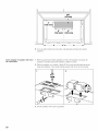
Prepare rear wall
4. Drill %" (9,5 mm) holes at "A", "B" and "C"
_ CAUTION: Wear safety goggles when drilling holes in the cabinet bottom.
5. Cut out the 2" (50,8 mm) hole at "D". This hole is for the power supply cord.
Note: If the cabinet is metal, use the nylon grommet around the opening to protect
the cord.
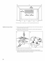
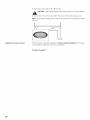
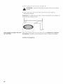
For wall venting installation you need to cut out an opening on the rear wall.
_ AUTION: If exhaust adaptor is positioned outside considerrecommended dimensions, otherwise grease-laden air will discharge into
house structure.
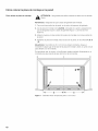
1. Mark the centerline (See Attaching the mounting plate to the wall) % (10 mm)
down from the top of the mounting plate.
2. Using measuring tape, measure out 6" (152 mm) on both sides of the centerline,
and mark.
3. Measure down 4" (102 mm) from the mark made in Step 1, and mark.
4. Using a straight edge, draw the 2 horizontal level lines through the marks made in
Steps 1 and 3.
5. Draw the 2 vertical plumb lines down from the marks made in Step 2. to
complete the 12" x 4" (304 x 102 mm) rectangle. This is the venting cutout area.
The 12" x 4" (305 x 102 mm) cutout area must align with the wall damper vent
(where the damper assembly will be installed) on the back of the microwave oven.
Note: Cutout must be free of any obstructions so that the vent fits properly, and the
damper hinge opens fully and swings freely.
21

m
li2 mm)l (152 mm) (152 mm)
1_ 6. = _ 6, = !
ooooo,oooooooooo
oooooooooooTooo_oooooo
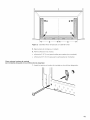
6. Using a saber or keyhole saw, cut out this area through the rear wall.
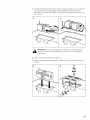
Adapting microwave blower 1. Remove and save the screws holding the blower motor and the blower plate. Lift
up the blower plate and put it aside.
2. Carefully pull out the blower unit and rotate 90° so that fan blade openings are
facing out the top of the microwave
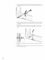
3. Rotate the blower unit counterclockwise 180°.
4. Gently remove the wires from the grooves. Reroute the wires through the
grooves on other side of the blower unit. Rotate blower unit 90° so that fan blade
openings are facing out the back of the microwave.
22

_ AUTION: Do not pull or stretch the blower unit wiring. Make sure thewires are not pinched, and that they are properly secured.
5. Place the blower unit back into the opening.
6. Replace the blower plate and secure with the srews removed in Step 1.
7. Attach the exhaust adapter to the rear of the oven by sliding it into the guides.
Push in securely until it is in the lower locking tabs.
Make sure the damper hinge swings freely.
23

7,
Proceed on page 27.
24

Room venting
Prepare upper cabinet 1. Remove power to outlet.
2. Remove all contents from upper cabinet.
3. Tape the TOP CABINET TEMPLATE onto the bottom surface. Make sure the
template centerline aligns with the vertical line on the wall. Rear wall arrows must
be against rear wall.
i
i
I
i
i
I
I
I
I
I
i
i
i
I
ooooooooooooloOOOOOOOOOOO
L ooooooooooo ooooooooooo
I
Note: For recessed cabinet bottom, trim the template edges so that it fits inside the
recessed area. The template has trim lines to use as guides.
©
i
i
i
i
i
i ilc
ooooooooooooloooooooooooo il(
ooooooooooo,i, ooooooooooo _
25

Adapting microwave blower
4. Drill %" (9,5 mm) holes at "A", "B" and "C"
_ CAUTION: Wear safety goggles when drilling holes in the cabinet bottom.
5. Cut out the 2" (50,8 mm) hole at "D". This hole is for the power supply cord.
Note: If the cabinet is metal, use the nylon grommet around the opening to protect
the cord.
This microwave is shipped assembled for Room Venting Installation. The blower
unit is already in place and must not to be adapted.
Proceed on page 27.
26

Mounting the microwave
oven
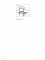
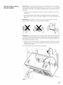
Note: If the bottom of the upper cabinet is recessed or has front overhang, you will
need to prepare 2" x 2" (51 mm x 51 mm - depth equivalent to cabinet recess or
overhang) filler blocks to provide additional support for the bolts:
÷ mark the center of each filler block and drill a % (9,5 mm) diameter hole
÷ align filler blocks over the three openings on top of the microwave oven and
attach with masking tape (see Figure 1)
Note: Use at least two people to install the microwave oven. Do not grip or use
handle during the installation.
Note: When mounting the microwave oven, thread power cord through hole in
bottom of top cabinet. Keep the cord tight and do not pinch it, especially when
mounting flush to bottom of cabinet. Do not pull the cord to lift the oven.
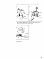
1. Lift the microwave, tilt it forward, and hook slots at back bottom edge onto four
lower tabs of the mounting plate.
2. Rotate the front of the oven up against cabinet bottom.
J L
Figure 1
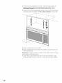
3. Insert a self-aligning screw through top center cabinet hole. Temporarily secure
the oven by turning the screw at least two full turns after the threads have
engaged.
27

4. Insert the two remaining self-aligning screws through outer top cabinet holes.
Turn two full turns on each screw.
5. Tighten center screw completely.
6. Tighten the outer two screws completely to the top of the microwave oven.
Note: While tightening screws, hold the microwave oven in place against the wall
and the top cabinet
7. Install grease filters by sliding them into the side slots, then pushing up and
toward oven to lock.
28
@
@
@

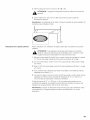
Hood exhaust
When venting exhaust to the oustside, hood exhaust ducts will be required. Read
the following carefully.
Note: It is important that venting be installed using the most direct route and with
as few elbows as possible. This ensures clear venting of exhaust and helps prevent
blockages. Also, make sure dampers swing freely and nothing is blocking the ducts.
Exhaust connection
The hood exhaust has been designed to mate with a standard 31A"x 10" (82 x 254
mm) rectangular duct. If a round duct is required, a rectangular-to-round transition
adaptor must be used. Do not use less than a 6" (152 mm) diameter duct.
Maximum Duct Length For satisfactory air movement, the total duct length of 31A" x 10" (82 x 254 mm)
rectangular or 6" (152 mm) diameter round should not exceed 120 equivalent
feet (36,5 m).
Elbows, transitions, wall and
roof caps etc.
cause additional resistance to airflow and are equivalent to a section of straight duct
which is longer than their actual physical size. When calculating the total duct
length, add the equivalent lengths of all transitions and adaptors plus the length of
all straight duct sections. The chart below shows you how to calculate total
equivalent ductwork length using the approximate feet of equivalent length of some
typical ducts:
Number
Duct Pieces Equivalent Length x used Equivalent Length
Rectangular-to-Round
Transition Adaptor*
5ft(1,5m)
= ftorm
Wall Cap
40 ft (12,2 m)
90° Elbow 1Oft (3m)
45° Elbow 5ft (1,5 m)
90° Elbow 25 ft (7,6 m)
45° Elbow 5ft (1,5 m)
Roof Cap 24 ft (7,3 m)
= ftorm
= ftorm
= ftorm
= ftorm
= ftorm
= ftorm
29

Number Equivalent Length
Duct Pieces Equivalent Length x used
[_ Straight Duct 6" (152 mm)
Round or
31_"x 10" (82 x 254 mm)
Rectangular
1ft(O,3 m) x ( ) -- ftorm
Total Ductwork = ft or m
* If a rectangular-to-round transition adapter is used, first make sure Equivalent lengths of duct pieces are based on
the damper hinge of the microwave swings freely. If necessary, cut actual tests and reflect requirements for good
the damper to fit, using the tin snips, in order to allow free venting performance with any vent hood.
movement.
Service
Contact our Service department ifyour appliance needs repair. Our central
Customer Service Center (see below) will also be happy to supply you with details
on a center close to you.
When you contact our customer service, please have the E number and the FD
number for your appliance available.
You can find the identification plate with these numbers on the inside of the
appliance.
Questions? Please contact us. We look forward to hearing from you!
1-800-944-2904
www.b0schappliances.c0m
5551 McFaddenAve.
HuntingtonBeach,CA92649
3O

Contenido
Seguridad ..................................... 32
Instrucciones de seguridad importantes ............................ 32
Antes de empezar ................................................. 35
Requisitos de ubicacion ............................................. 36
Procedimiento de instalacion ...................................... 37
Como retirar la placa de montaje ...................................... 37
Como encontrar los montantes de pared ............................... 38
Posibles configuraciones de los montantes de pared ..................... 38
Como colocar la placa de montaje en la pared .......................... 40
Tipos de instalacion ................................................ 44
Ventilacion de techo ................................................ 45
Ventilacion de pared ................................................ 48
Ventilacion de ambiente ............................................. 53
Como montar el homo de microondas ................................. 55
Escape de campana ................................................ 57
Servicio tecnico ................................................... 59
31

Seguridad
Instrucciones de seguridad
importantes
LEA Y GUARDE ESTAS INSTRUCCIONES
Importante
CONSERVE ESTAS INSTRUCCIONES PARA USO DEL INSPECTOR DE
ELECTRICIDAD LOCAL.
DEJE ESTAS INSTRUCCIONES CON EL ELECTRODOMESTICO CUANDO HAYA
FINALIZADO LA INSTALACION.
_ VlSO: Si no sigue la informacion de este manual exactamente, se puedeocasionar un incendio o una descarga electrica que puede causar da_os
materiales o lesiones personales.
Examine su horno
Seguridad con el manejo del
electrodomestico
Uso previsto
Desembale el horno, retire toda la cinta y el material de embalaje, y examine el
homo para asegurarse de que no tenga da_os tales como abolladuras, trabas de la
puerta rotas ni rajaduras en la puerta. Si se encuentra da_ado, notifique al
distribuidor de inmediato. No instale el homo si se encuentra da_ado.
Destruya el embalaje despues de desembalar el electrodomestico. Nunca deje que
los ni_os jueguen con el material de embalaje.
La unidad es pesada, y se requieren, al menos, dos personas o un equipo
adecuado para trasladarla.
Las superficies ocultas pueden tener bordes filosos. Proceda con cuidado al
intentar tomar el electrodomestico por la parte trasera o desde abajo.
_ TTENCION: Solamente para uso general de ventilacion. No use elproducto para extraer materiales ni vapores peligrosos o explosivos.
Instrucciones para la conexion a tierra Este electrodomestico debe estar correctamente conectado a tierra. La conexion a
tierra reduce el riesgo de descarga electrica proporcionando un cable de escape
para la corriente electrica si se produce un cortocircuito electrico. Este homo viene
equipado con un cable con un hilo de conexion a tierra y un enchufe para conexion
a tierra. El enchufe debe colocarse en una toma de corriente que este
correctamente instalada y conectada a tierra.
_ VlSO: El uso inadecuado de la conexion a tierra puede tener comoconsecuencia una descarga electrica.
Consulte a un electricista o a un centro de servicio tecnico calificado si no
comprende la totalidad de las instrucciones de conexion a tierra o si tiene alguna
duda respecto de si el homo esta correctamente conectado a tierra.
32

Instrucciones de seguridad
importantes
LEA Y GUARDE ESTAS INSTRUCCIONES
Requisitos electricos
No use un cable de extension. Si el cable de alimentaci0n del producto es
demasiado corto, haga que un electricista calificado instale un receptaculo de tres
ranuras. Este horno debe enchufarse en un circuito de 60 hertz por separado,
con la capacidad electrica nominal que se muestra en la tabla de especificaciones.
Cuando el homo esta en un circuito con otro equipo, es posible que se requiera un
aumento en los tiempos de coccion y que los fusibles se quemen.
Ei homo de microondas funciona con la corriente domestica estandar, 110-120 V.
@
@
@
@
una toma de corriente conectada a tierra de tres espigas
120 V, 60 Hz, CA Onicamente.
15 A de suministro electrico con un fusible o un disyuntor.
1.6 kilovatios
Este producto debe conectarse a un circuito de suministro con el voltaje y la
frecuencia adecuados. El tama_o del cable debe cumplir con los requisitos del
Codigo Electrico Nacional o con el codigo local aplicable para esta capacidad
nominal. El cable de alimentaci0n electrica y el enchufe deben Ilevarse a una toma
de corriente conectada a tierra individual de circuito derivado de 15 a 20 A por
separado. La caja de la toma de corriente debe estar ubicada en el gabinete por
encima del homo de microondas. La caja de la toma de corriente y el circuito de
suministro deben ser instalados por un electricista calificado y de conformidad con
el Codigo Electrico Nacional o con el codigo local aplicable.
El voltaje usado debe ser el mismo que el especificado en este horno de
microondas. Usar un voltaje mayor es peligroso y puede provocar un incendio o
da_os al horno. Usar un voltaje menor hara que los alimentos se cocinen
lentamente. El distribuidor no es responsable de ningOn da_o que se produzca por
el uso del homo con un voltaje que no sea el especificado.
Requisitos de ubicacion Verifique la abertura donde se instalara el homo de microondas. La ubicacion debe
brindar:
Dimensiones minimas para la instalacion (Consulte la ilustraci0n Dimensiones
para la instalacion)
Como mfnimo, un montante de madera para pared de 2" x 4" (50.8 x 101.6 mm)
y, como mfnimo, un panel de yeso o yeso/enlucido de 3/8" (9.5 mm) de espesor
dentro de la abertura del gabinete.
Soporte para peso de 150 Ib (68 kg), que incluye el homo de microondas y los
artfculos colocados en su interior yen el gabinete superior.
Toma de corriente electrica con conexion a tierra dentro del gabinete superior.
(Consulte la seccion Requisitos electricos).
Notas:
Si instala el homo de microondas cerca de una pared izquierda, asegOrese de
que haya una distancia de, al menos, 7" (178 mm) entre la pared y el homo de
microondas, para que la puerta se pueda abrir completamente.
AIgunos materiales para gabinetes y de construccion no estan diseSados para
soportar el calor generado por el horno de microondas para cocinar. Hable con
su constructor o proveedor de gabinetes para asegurarse de que los materiales
utilizados no se decoloraran, deslaminaran ni sufriran otros da_os.
33

Instrucciones de seguridad
importantes
LEA Y GUARDE ESTAS INSTRUCCIONES
Control de la continuidad de la
conexion a tierra
Seguridad con la electricidad
Seguridad de los equipos
relacionados
Seguridad en el servicio tecnico y las
reparaciones
El instalador debe realizar un control de la continuidad de la conexion a tierra en la
caja de la toma de corriente antes de la instalacion para asegurarse de que la caja
de la toma de corriente esta correctamente conectada a tierra. Si no esta
correctamente conectada a tierra, o si la caja de la toma de corriente no cumple
con los Requisitos electricos, se debe contratar a un electricista calificado para
corregir cualquier deficiencia.
_ TTENCION: Por seguridad personal, retire el fusible de su hogar oapague el disyuntor en la caja de fusibles antes de comenzar la instalacion
para evitar lesiones graves o fatales como consecuencia de una descarga
electrica. Trabe el disyuntor para impedir que se encienda accidentalmente
la alimentaci0n electrica.
AsegOrese de que el electrodomestico sea correctamente instalado y conectado a
tierra por un tecnico calificado.
El instalador debe mostrar al propietario la ubicacion del disyuntor o el fusible.
Marquela para recordarla mas facilmente.
En ninguna circunstancia, no corte ni retire la espiga de conexion a tierra. Debe
enchufarse en un receptaculo de conexion a tierra compatible para evitar la
descarga electrica. Si tiene alguna duda respecto de si el receptaculo de pared esta
correctamente conectado a tierra, el cliente debe solicitar la verificacion de un
electricista calificado. No use un cable de extension.
_ TTENCION: Por seguridad personal, este producto no puede instalarseen instalaciones de gabinete, como una isla o peninsula. Debe montarse
en un gabinete superior y en una pared.
_ AVISO: Para reducir el riesgo de incendio, solo utilice conductos de metal.
_ VlSO: No repare ni cambie ninguna parte del electrodomestico, a menosque se recomiende especfficamente en los manuales. Nunca modifique ni
altere la construccion del electrodomestico. La instalacion, el servicio
tecnico o el mantenimiento incorrectos pueden causar lesiones o da_os
materiales. Consulte este manual para su orientacion. Remita todas las
demas reparaciones a un centro de servicio tecnico autorizado por la
fabrica.
34

Antes de empezar
Herramientas y piezas
necesarias
÷ Destornillador Phillips n.° 1
÷ Lapiz
÷ Regla o cinta metrica y borde recto
÷ Taladro con brocas de 3/16"(5 mm), 1/2"(13 mm) y 5/8" (16 mm)
÷ Guantes
÷ Sierra (reciproca, caladora o de punta)
÷ Localizador de montantes o martillo
÷ Gafas de seguridad
÷ Nivel
÷ Cinta para conductos o de enmascarar
opcionales
÷ Escuadra de carpintero
÷ Tijeras de hojalatero (para cortar el regulador)
÷ Tijeras (para cortar la plantilla del gabinete superior)
÷ Bloques de relleno o recortes de madera (para instalaciones de gabinete inferior
empotrado)
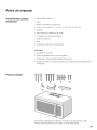
Piezas incluidas
A
%
E
B C D
Encontrara los elementos de instalacion incluidos en el paquete de la unidad.
Verifique para asegurarse de que cuente con todas estas piezas:
35

÷ A Tornillos mecanizados autoalineables: 1A"-28 x 31A'' (6-0,9 x 83 mm)
÷ B Pernos articulados: 3/16"x 3" (5 x 76 mm)
÷ C Alas articuladas
÷ D Tornillos para madera: _A"x 2" (6 x 51 mm)
÷ E Correa del cable de alimentacion
÷ F Arandela de nylon (para gabinetes de metal)
÷ G Adaptador del escape
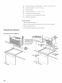
Requisitos de ubicaci6n
No se muestran:
÷ Plantilla del gabinete superior
÷ Placa de montaje (sujetar a la parte posterior del homo de microondas)
÷ Filtros de grasa de aluminio
÷ Filtro de carbon (sujeta al homo de microondas)
Dimensiones para la instalacion
12" (305mm) min.
127/8" (327mm) max.
\
Torna de corriente
conectada a tierra
(dentro del gabinete
que se encuentra
arriba del homo)
I
161/2"
min.
(349mm)
min.
2" (51 mm)
66" (1676mm)min.
30" (762mm)
min.
36

Dimensiones del producto
153/4"
(400mm)
L
297/8"
I 153/8"
(760mm) __,_ (390mm)
161/2"
419rnm)
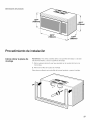
Procedimiento de instalaci6n
C6mo retirar la placa de
montaje
Advertencia: Para evitar posibles da_os a la superficie de trabajo o a la base
del electrodomestico, cubra la superficie de trabajo.
1. Retire cualquier elemento que haya quedado en la cavidad del homo de
microondas.
2. Retire los tornillos de la placa de montaje.
Esta placa se utilizara como plantiNade la pared posterior y para el montaje.
37

C6mo encontrar los
montantes de pared
3. Vuelva a instalar los tornillos en los orificios de donde los retiro.
Advertencia: Para evitar da_ar el homo de microondas, no sujete ni use la puerta
ni la manija de la puerta mientras esta manejando el homo de microondas.
Advertencia: El homo de microondas debe conectarse, al menos, a un montante
de pared. Si no hay montantes de pared en la abertura del gabinete, no instale el
horno de microondas.
1. Ubique los bordes de los montantes de pared dentro del gabinete usando:
÷ un Iocalizador de montantes o
,
un martillo (dando golpecitos suaves en toda la superficie de montaje hasta
escuchar un sonido de haber golpeado algo solido).
Coloque una marca a mitad de camino entre los bordes y trace una linea hacia
el centro de los montantes (Consulte las posibles configuraciones de los
montantes de pared).
Posibles configuraciones de los montantes de pared
Estas representaciones muestran ejemplos de las configuraciones preferidas de
instalacion con la placa de montaje.
Advertencia: Se debe tener cuidado al perforar orificios. Los cables electricos
pueden estar empotrados en el del revestimiento de pared y el contacto con ellos
puede ocasionar una descarga electrica.
Sin montantes de pared en los
orificios de las esquinas
Advertencia: Si el montante de pared se encuentra a una distancia de 61/4''
(159 mm) de la linea central vertical, s01ose puede realizar una instalacion con
ventilacion de ambiente (recirculacion) o ventilacion de techo.
38

Montante de pared en uno de los
orificios de las esquinas
Montantes de pared en ambos
orificios de las esquinas
I
39

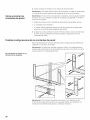
C6mo colocar la placa de montaje en la pared
Como alinear la placa de montaje
_ TTENCION: Use guantes para evitar cortarse los dedos con los bordes
filosos.
Advertencia: AsegOrese de que la base del gabinete este nivelada.
1. Trace una Ifnea vertical en la pared, en el centro del espacio del gabinete.
2. Use la placa de montaje como plantilla, coloquela en la pared y asegOrese de
que las leng(Jetas toquen la base del gabinete (Figura 1) o la Ifnea de nivel
(Figura 2).
3. Alinee la muesca y la linea central de la placa de montaje con la Ifnea central de
la pared.
4. Sujetando la placa de montaje, trace circulos en la pared, en los orificios A, B, C
yD.
Advertencia: Si el orificio A, B, C o D no toca ningOn montante, ubique un
montante en algOn lugar de la base de la placa de montaje y trace un quinto circulo
para alinearlo con el montante.
Es importante usar, al menos, un tornillo para madera montado firmemente en un
montante para que soporte el peso del homo de microondas.
I
B
C D
Figura 1
-i
i
- Gabinete inferior empotrado piano o con marco
y
4O

C
B
4¸¸¸¸¸¸¸¸¸"¸¸¸.....
D
-i
m m
Figura 2 - Gabinete inferior empotrado con saliente frontal
m
5. Deje la placa de montaje a un costado
6. Perfore orificios en los circulos:
÷ orificios de 3/16" (5 mm) para tornillos para madera (con montante)
÷ orificios de 5/8" (16 mm) para pernos articulados (sin montante)
Como colocar la placa de montaje
(sin montantes de pared en los orificios de las esquinas)
1. Inserte los pernos en la placa de montaje por los orificios designados.
41

2. Una las alas articuladas a cada perno desde la parte posterior de la placa de
montaje. Deje espacio suficiente para que las alas articuladas atraviesen la pared
y se abran.
3. Coloque la placa de montaje contra la pared y aseg0rese de que las leng0etas
toquen la base del gabinete o la linea de nivel (consulte "Como alinear la placa
de montaje").
4. Empuje los pernos a traves del panel de yeso y aprietelos con la mano para
asegurarse de que las tuercas articuladas se hayan abierto contra el panel de
yeso.
5. Verifique que la placa este correctamente centrada, y aseg0rese de que este
nivelada.
6. Apriete firmemente todos los tornillos, incluido el quinto tornillo para madera en la
base de la placa de montaje.
42

C6mo colocar la placa de montaje
(Montante de pared en uno de los orificios de las esquinas)
1. Inserte los pernos y los tornillos para madera en la placa de montaje por los
orificios designados.
2. Una las alas articuladas desde la parte posterior de la placa de montaje en cada
perno. Deje espacio suficiente para que las alas articuladas atraviesen la pared y
se abran.
,
,
,
Coloque la placa de montaje contra la pared y aseg0rese de que las leng0etas
toquen la base del gabinete o la Ifnea de nivel (consulte "Como alinear la placa
de montaje").
Empuje los pernos a traves del panel de yeso y aprietelos con la mano para
asegurarse de que las alas articuladas se hayan abierto contra el panel de yeso.
Verifique que la placa este correctamente centrada, y aseg0rese de que este
nivelada.
6. Apriete firmemente todos los tornillos y los pernos.
Como colocar la placa de montaje
(Montantes de pared en ambos orificios de las esquinas)
,
,
,
Inserte los tornillos para madera en la placa de montaje por los orificios
designados.
Coloque la placa de montaje contra la pared y aseg0rese de que las leng0etas
toquen la base del gabinete o la Ifnea de nivel (consulte "Como alinear la placa
de montaje").
Verifique que la placa este correctamente centrada, y aseg0rese de que este
nivelada.
4. Apriete todos los tornillos firmemente.
43

Tipos de instalaci6n
VENTILACION DE
TECHO
contin0e en la pagina 45
VENTILACION DE
PARED
contin0e en la pagina 48
VENTILACION DE
AMBIENTE
contin0e en la pagina 53
44

Ventilaci6n de techo
Preparacion del gabinete superior
1. Corte la alimentacion electrica a la toma de corriente.
2. Retire todo el contenido del gabinete superior.
3. Pegue la PLANTILLA DEL GABINETE SUPERIOR a la superficie inferior con
cinta. Aseg0rese de que la linea central de la plantilla este alineada con la linea
vertical de la pared. Las fiechas de la pared posterior deben estar contra la pared
posterior.
i
i
I
i
i
I
I
I
I
I
i
i
i
I
3 OOOOOOOOOOOOIOOOOOOOOOOOO
L ooooooooooo.,ooooooooooo
I
_'_
Advertencia: Para la base del gabinete empotrado, recorte los bordes de la
plantilla para que calce dentro del area empotrada. La plantilla tiene lineas para
recortar que puede utilizar como gu[a.
©
i
i
i
i
i
i Ic
o ooo o oo o ooo olooo oo ooo oo o o I(
o o o o o o o o o o o,i,o o o o o o o o o o o _
45

4. Perfore orificios de 3/8" (9.5 mm) en "A", "B" y "C".
,_ ATTENCION: Use gafas de seguridad al perforar orificios en la base delgabinete.
5. Cale el orificio de 2" (50.8 mm) en "D". Este orificio es para el cable de
alimentacion electrica.
Advertencia: Si el gabinete es de metal, coloque la arandela de nylon alrededor de
la abertura para proteger el cable.
6. Cale el area sombreada "E" con una sierra redproca o de punta.
Como adaptar el soplador del horno
de microondas
1. Retire y guarde los tornillos sujetando el motor del soplador y la placa del
soplador. Levante la placa del soplador y dejela a un lado.
2. Retire el soplador con cuidado y girelo 90° de modo que las aberturas de las
hojas del ventilador miren hacia la parte superior del homo de microondas.
1. _ 2.
3. Vuelva a colocar el soplador en la abertura.
,_ ATTENCION: No tire del cableado del soplador ni Io estire. Aseg0resede que los cables no esten pellizcados y de que esten correctamente
asegurados.
46

4. Vuelva a colocar la placa del soplador y aseg0rela con los tornillos que retiro en
el paso 1.
5. Coloque el adaptador del escape en la parte superior de la placa del soplador
deslizandolo por las gu[as. Emp0jelo firmemente hasta que quede en las
leng0etas de bloqueo.
Aseg0rese de que la bisagra reguladora se mueva libremente.
ContinQe en la pagina 55.
47

Ventilaci6n de pared
Preparacion del gabinete superior
1. Corte la alimentacion electrica a la toma de corriente.
2. Retire todo el contenido del gabinete superior.
3. Pegue la PLANTILLA DEL GABINETE SUPERIOR a la superficie inferior con
cinta. Aseg0rese de que la linea central de la plantilla este alineada con la linea
vertical de la pared. Las fiechas de la pared posterior deben estar contra la pared
posterior.
i
i
I
i
i
I
I
I
I
I
i
i
i
I
3 OOOOOOOOOOOOIOOOOOOOOOOOO
L ooooooooooo.,ooooooooooo
I
_'_
Advertencia: Para la base del gabinete empotrado, recorte los bordes de la
plantilla para que calce dentro del area empotrada. La plantilla tiene lineas para
recortar que puede utilizar como gu[a.
©
i
i
i
i
i
i Ic
o ooo o oo o ooo olooo oo ooo oo o o I(
o o o o o o o o o o o,i,o o o o o o o o o o o _
48

Preparacion de la pared posterior
4. Perfore orificios de 3/8" (9.5 mm) en "A", "B" y "C".
_ TTENCION: Use gafas de seguridad al perforar orificios en la base delgabinete.
5. Cale el orificio de 2" (50.8 mm) en "D". Este orificio es para el cable de
alimentacion electrica.
Advertencia: Si el gabinete es de metal, coloque la arandela de nylon alrededor de
la abertura para proteger el cable.
Para la instalacion con ventilacion de pared, debe calar una abertura en la pared
posterior.
_ TTENCION: Si el adaptador del escape esta ubicado en el exterior,tenga en cuenta las dimensiones recomendadas. De Io contrario, el aire
cargado de grasa se descargara en la estructura de la casa.
1. Marque la Ifnea central (Consulte Como colocar la placa de montaje en la pared)
% (10 mm) hacia abajo desde la parte superior de la placa de montaje.
2. Con una cinta metrica, mida 6" (152 mm) a cada lado de la Ifneacentral y haga
una marca.
3. Mida 4" (102 mm) hacia abajo a partir de la marca realizada en el Paso 1, y haga
una marca.
,
,
Con un borde recto, dibuje las dos lineas horizontales a nivel hasta las marcas
realizadas en los Pasos 1 y 3.
Trace las dos lineas a plomo en forma vertical hacia abajo, a partir de las marcas
realizadas en el Paso 2 para completar el rectangulo de 12" x 4" (304 mm x
102 mm). Esta es el area para el hueco de ventilacion.
El area del hueco de 12" x 4" (305 mm x 102 mm) debe estar alineada con la
ventilacion del regulador de ventilacion pared (donde se instalara el conjunto del
regulador) en la parte posterior del homo de microondas.
Advertencia: El hueco no debe tenet obstrucciones para que la ventilacion calce
correctamente y, la bisagra reguladora se abra completamente y se mueva
libremente.
49

m
li2 mm)l (152 mm) (152 mm)
1_ 6. = _ 6, = !
ooooo,oooooooooo
oooooooooooTooo_oooooo
6. Con una sierra reciproca o de punta, cale esta area a traves de la pared
posterior.
Como adaptar el soplador del horno
de microondas
1. Retire y guarde los tornillos sujetando el motor del soplador y la placa del
soplador. Levante la placa del soplador y dejela a un lado.
2. Retire el soplador con cuidado y gfrelo 90° de modo que las aberturas de las
hojas del ventilador miren hacia la parte superior del homo de microondas.
1. _ 2.
3. Gire el soplador 180° hacia la izquierda.
5O

4. Quite suavemente los cables de las ranuras. Pase los cables por las ranuras del
otro lado de la unidad del soplador. Gire el soplador 90° de modo que las
aberturas de las hojas del ventilador miren hacia la parte posterior del homo de
microondas.
,_ ATTENCION: No tire del cableado del soplador ni Io estire. Aseg0resede que los cables no esten pellizcados y de que esten correctamente
asegurados.
5. Vuelva a colocar el soplador en la abertura.
6. Vuelva a colocar la placa del soplador y aseg0rela con los tornillos que retiro en
el Paso 1.
5. 6.
51

7. Coloque el adaptador del escape en la parte posterior del homo deslizandolo por
las guias. Emp0jelo firmemente hasta que quede en las lengOetas de bloqueo
inferiores.
Aseg0rese de que la bisagra reguladora se mueva libremente.
,
ContinQe en la pagina 55.
52

Ventilaci6n de ambiente
Preparacion del gabinete superior
1. Corte la alimentacion electrica a la toma de corriente.
2. Retire todo el contenido del gabinete superior.
3. Pegue la PLANTILLA DEL GABINETE SUPERIOR a la superficie inferior con
cinta. Aseg0rese de que la linea central de la plantilla este alineada con la linea
vertical de la pared. Las fiechas de la pared posterior deben estar contra la pared
posterior.
i
i
I
i
i
I
I
I
I
I
i
i
i
I
3 OOOOOOOOOOOOIOOOOOOOOOOOO
L ooooooooooo.,ooooooooooo
I
_'_
Advertencia: Para la base del gabinete empotrado, recorte los bordes de la
plantilla para que calce dentro del area empotrada. La plantilla tiene lineas para
recortar que puede utilizar como gu[a.
©
i
i
i
i
i
i Ic
o ooo o oo o ooo olooo oo ooo oo o o I(
o o o o o o o o o o o,i,o o o o o o o o o o o _
53

Como adaptar el soplador del horno
de microondas
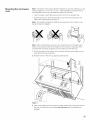
4. Perfore orificios de 3/8" (9.5 mm) en "A", "B" y "C".
_ TTENCION: Use gafas de seguridad al _erforar orificios en la base delgabinete.
5. Cale el orificio de 2" (50.8 mm) en "D". Este orificio es para el cable de
alimentacion electrica.
Advertencia: Si el gabinete es de metal, coloque la arandela de nylon alrededor de
la abertura para proteger el cable.
Este homo de microondas se envia armado para una instalacion de ventilacion
de ambiente. El soplador ya se encuentra en su lugar y no debe set adaptado.
Contin6e en la pagina 55.
54

C6mo montar el horno
de microondas
Advertencia: Si la base del gabinete superior esta empotrada o tiene una saliente
frontal, debera preparar bloques de relleno de 2" x 2" (51 mm x 51 mm, profundidad
equivalente al empotrado o a la saliente del gabinete) para brindar mayor soporte a
los pernos:
÷ marque el centro de cada bloque de relleno y perfore un orificio de % (9.5 mm)
de diametro
÷ alinee los bloques de relleno sobre las tres aberturas que se encuentran en la
parte superior del homo de microondas y sujetelos con cinta de enmascarar (ver
Figura 1)
Advertencia: Se necesitan, al menos, dos personas para instalar el homo de
microondas. No sujete ni use la manija durante la instalacion.
Advertencia: AI montar el homo de microondas, pase el cable de alimentacion por
el orificio de la base del gabinete superior. Mantenga el cable tirante sin pellizcarlo,
especialmente al montar el homo de microondas a ras de la base del gabinete. No
tire del cable para levantar el horno.
1. Levante el homo de microondas, inclinelo hacia adelante y enganche las cuatro
leng0etas inferiores de la placa de montaje en las ranuras que se encuentran en
el borde inferior posterior.
2. Gire el frente del homo contra la base del gabinete.
J L
Figura 1
55

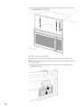
3. Inserte un tornillo autoalienable en el orificio central de la parte superior del
gabinete. Asegure el homo temporalmente girando el tornillo, al menos,
dos vueltas completas una vez que se hayan enganchado las roscas.
4. Inserte los dos tornillos autoalienables restantes en los orificios de los extremos
de la parte superior del gabinete. De dos vueltas completas en cada tornillo.
5. Ajuste completamente el tornillo central.
6. Ajuste completamente los dos tornillos de los extremos a la parte superior del
homo de microondas.
Advertencia: AI ajustar los tornillos, sostenga el homo de microondas en su lugar
contra la pared y el gabinete superior.
7. Instale filtros de grasa deslizandolos dentro de las ranuras laterales y, luego,
empujandolos hacia arriba y en direccion al homo para que queden trabados.
56

Escape de campana
J
0
@
@
AI ventilar el escape hacia el exterior, se necesitarfln conductos del escape de
campana. Lea detenidamente las siguientes instrucciones.
Advertencia: Es importante instalar la ventilacion utilizando la via mils directa y la
minima cantidad de codos posible. Esto asegura la ventilacion libre del escape y
ayuda a evitar obstrucciones. Asimismo, asegOrese de que los reguladores se
muevan libremente y que nada obstruya los conductos.
Conexion del escape El escape de campana ha sido diseSado para conectarse a un conducto
rectangular estflndar de 31A"x 10" (82 mm x 254 mm). Si se requiere un conducto
redondo, debe utilizar un adaptador de transicion de rectangular a redondo. No
use un conducto de menos de 6" (152 mm) de diametro.
Longitud maxima del conducto Para garantizar un movimiento de aire aceptable, la Iongitud total del conducto
rectangular de 31A"x 10" (82 mm x 254 mm) o redondo de 6" (152 mm) de diflmetro
no debe exceder el equivalente a 120 pies (36.5 m).
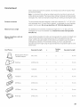
Codos, transiciones, tapas de
pared y techo, etc.
Generan resistencia adicional al fiujo de aire y equivalen a la seccion del conducto
recto que es mils largo que su tamafio fisico real. AI calcular la Iongitud total del
conducto, sume las longitudes equivalentes de todas las transiciones y de los
adaptadores, y la Iongitud de todas las secciones del conducto recto. El cuadro
que aparece a continuacion le muestra como calcular la Iongitud total equivalente
del sistema de conductos utilizando la cantidad aproximada de pies de Iongitud
equivalente de algunos conductos tipicos:
57

Cantidad Longitud
Piezas de conductos Longitud equivalente x
usada equivalente
Adaptador de transicion 5pies (1.5 m)
de rectangular a redondo*
pies o m
Tapa de pared
40 pies (12.2 m) pies o m
(_ Codo de 90°
Codo de 45°
10 pies (3m)
5 pies (1.5 m) z
pies o m
pies o m
Codo de 90°
25 pies (7.6 m) pies o m
Codo de 45°
5 pies (1.5 m) pies o m
Tapadetecho
24 pies (7.3 m) pies o m
Conducto recto redondo
de 6" (152 mm) o
Rectangular de 31A"x 10"
(82 mm x 254 mm)
1 pie (0.3 m) pies o m
Sistema de conductos pies o m
m.
total
* Si se usa un adaptador de transicion de rectangular a redondo, Las longitudes equivalentes de las piezas de
primero asegOrese de que la bisagra reguladora del homo de conductos se basan en pruebas reales y refiejan los
microondas se mueva libremente. Si es necesario, corte el requisites para un buen rendimiento de ventilaci6n
regulador para que calce, con tijeras de hojalatero, para permitir con cualquier campana de ventilaci6n.
que haya movimiento libre.
58

Servicio t6cnico
Si necesita reparar el electrodomestico, Ilame a nuestro Departamento de Servicio
Tecnico. Nuestro Centro de Servicio al Cliente principal (vea a continuacion)
tambien se complacera en brindarle la informacion sobre un centro cercano a su
domicilio.
Cuando Ilame a nuestro servicio al cliente, tenga a la mano el n0mero E y el n0mero
FD de su electrodomestico.
Puede encontrar la placa de identificacion con estos n0meros en el interior del
electrodomestico.
sPreguntas? Comunfquese con nosotros, iEsperamos tenet noticias suyas pronto!
1-800-944-2904
www.b0schappliances.c0m
5551 McFaddenAve.
HuntingtonBeach,CA92649USA
59

9000423675oBl10289
BOSCH
5551 McFadden Ave., Huntington Beach, CA 92649 ol -800-944-2904
www.boschappliances.com (©BSH Home Appliances Corporation 2008
-
 1
1
-
 2
2
-
 3
3
-
 4
4
-
 5
5
-
 6
6
-
 7
7
-
 8
8
-
 9
9
-
 10
10
-
 11
11
-
 12
12
-
 13
13
-
 14
14
-
 15
15
-
 16
16
-
 17
17
-
 18
18
-
 19
19
-
 20
20
-
 21
21
-
 22
22
-
 23
23
-
 24
24
-
 25
25
-
 26
26
-
 27
27
-
 28
28
-
 29
29
-
 30
30
-
 31
31
-
 32
32
-
 33
33
-
 34
34
-
 35
35
-
 36
36
-
 37
37
-
 38
38
-
 39
39
-
 40
40
-
 41
41
-
 42
42
-
 43
43
-
 44
44
-
 45
45
-
 46
46
-
 47
47
-
 48
48
-
 49
49
-
 50
50
-
 51
51
-
 52
52
-
 53
53
-
 54
54
-
 55
55
-
 56
56
-
 57
57
-
 58
58
-
 59
59


Bosch HMV3061U/01 Guía de instalación
- Categoría
- Microondas
- Tipo
- Guía de instalación
- Este manual también es adecuado para
en otros idiomas
- English: Bosch HMV3061U/01 Installation guide
Artículos relacionados
Otros documentos
-
Jenn-Air AMV4204AAW Guía de instalación
-
Maytag MMV6178 Installation Instructions Manual
-
-
Whirlpool WML35011KW Guía de instalación
-
Kenmore 72162644200 Guía de instalación
-
 Kenmore Elite 72180804400 Guía de instalación
-
Whirlpool MH1150XMQ4 Guía de instalación
-
Frigidaire FPBM3077RFB Guía de instalación
-
Kenmore Pro 89393 Guía de instalación
-
Haier QVM7167BNTS Guía de instalación
