Bosch HMV5052U/02 Guía de instalación
- Categoría
- Microondas
- Tipo
- Guía de instalación
Este manual también es adecuado para

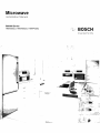
Microwave
Installation Manual
500/800 Series
HMV5052U, HMV8052U, HMVP052U
-";" BOSCH
,_,,,_-- ,!
Invented for life
,
-,_ ,,prm
J
j-
i...............................:" "" ¢*_J_#i,!_l_i_,_,_,,
'4:,__,_,'fsi'i'_',''''
!
:ii ..............

Table of Contents
Safety Definitions .......................................................... 3
IMPORTANT SAFETY INSTRUCTIONS ........................ 4
Appliance Handling Safety ................................................. 4
Safety Codes and Standards ............................................. 4
State of California Proposition 65 Warnings ................... 4
Electric Safety ....................................................................... 4
Microwave Safety ................................................................. 4
Related Equipment Safety .................................................. 5
Checklist for Installation ............................................... 6
Before You Begin ........................................................... 6
Removing Packaging .......................................................... 6
Tools and Parts Needed ..................................................... 6
Parts Included ....................................................................... 7
Location requirements ......................................................... 7
Power Requirements ........................................................... 8
Electrical Installation ..................................................... 8
Install Appliance ............................................................ 9
Removing the mounting plate ........................................... 9
Finding the wall studs ......................................................... 9
Possible wall stud configurations ..................................... 9
Attaching the mounting plate to the wall ...................... 10
Adapting microwave blower ........................................... 11
Preparing cabinet .............................................................. 12
Mounting the microwave oven ....................................... 12
Hood exhaust ..................................................................... 13
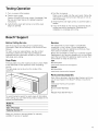
Testing Operation ........................................................ 15
Bosch ®Support ........................................................... 15
Before Calling Service ...................................................... 15
Data Plate ........................................................................... 15
Service ................................................................................ 15
Parts and Accessories ..................................................... 15
Questions?
1-800-944-2904
www.bosch-home.com
1901 Main Street, Suite 600
Irvine, CA 92614
We look forward to hearing from you!

Safety Definitions
WARNING
This indicates that death or serious injuries may
occur as a result of non-observance of this warning.
CAUTION
This indicates that minor or moderate injuries may
occur as a result of non-observance of this warning.
NOTICE: This indicates that damage to the appliance or
property may occur as a result of non-compliance with
this advisory.
Note: This alerts you to important information and/or
tips.

A
IMPORTANT SAFETY INSTRUCTIONS
READ AND SAVE THESE INSTRUCTIONS
INSTALLER: LEAVE THESE INSTRUCTIONS WITH THE
APPLIANCE AFTER INSTALLATION IS COMPLETE.
IMPORTANT: SAVE THESE INSTRUCTIONS FOR THE
LOCAL ELECTRICAL INSPECTOR'S USE.
WARNING
If the information in this manual is not followed exactly,
fire or shock may result causing property damage or
personal injury.
WARNING
Do not repair, replace or remove any part of the
appliance unless specifically recommended in the
manuals. Improper installation, service or maintenance
can cause injury or property damage. Refer to this
manual for guidance. All other servicing should be done
by a qualified technician.
Appliance Handling Safety
Unit is heavy and requires at least two people or proper
equipment to move.
Do not lift appliance by door handle.
Hidden surfaces may have sharp edges. Use caution
when reaching behind or under appliance.
Safety Codes and Standards
This appliance complies with the latest version of one or
more of the following standards:
o CAN/CSA C22.2 No. 61 - Household Cooking Ranges
o UL 858- Household Electric Ranges
o CAN/CSA C22.2 No. 150 - Microwave Ovens
o UL 923 - Microwave Cooking Appliances
o UL 507- Electric Fans
o CAN/CSA C22.2 No. 113 - Fans and Ventilators
o CSA C22.2 No. 64 - Household Cooking and Liquid-
Heating Appliances
o UL 1026 - Electric Household Cooking and Food
Serving Appliances
It is the responsibility of the owner and the installer to
determine if additional requirements and/or standards
apply to specific installations.
State of California Proposition 65
Warnings
WARNING
This product contains chemicals known to the State of
California to cause cancer, birth defects or other
reproductive harm.
Electric Safety
WARNING
Before you plug in an electrical cord or turn on power
supply, make sure all controls are in the OFF position.
For appliances equipped with a cord and plug, do not
cut or remove the ground prong. It must be plugged into
a matching grounding type receptacle to avoid electrical
shock. If there is any doubt as to whether the wall
receptacle is properly grounded, the customer should
have it checked by a qualified electrician.
If required by the National Electrical Code (or Canadian
Electrical Code), this appliance must be installed on a
separate branch circuit.
Installer - show the owner the location of the circuit
breaker or fuse. Mark it for easy reference.
Before installing, turn power OFF at the service panel.
Lock service panel to prevent power from being turned
ON accidentally.
Be sure your appliance is properly installed and
grounded by a qualified technician. Installation, electrical
connections and grounding must comply with all
applicable codes.
Microwave Safety
PRECAUTIONS TO BE OBSERVED BEFORE AND
DURING SERVICING TO AVOID POSSIBLE EXPOSURE
TO EXCESSIVE MICROWAVE ENERGY
o Do not operate or allow the oven to be operated with
the door open.
o Make the following safety checks on all ovens to be
serviced before activating the magnetron or other
microwave source, and make repairs as necessary:
1. Interlock operation
2. Proper door closing
3. Seal and sealing surfaces (arcing, wear, and other
damage)
4. Damage to or loosening of hinges and latches
5. Evidence of dropping or abuse
o Before turning on microwave power for any service
test or inspection within the microwave generating
compartments, check the magnetron, wave guide or
transmission line, and cavity for proper alignment,
integrity, and connection.
o Any defective or misadjusted components in the
interlock, monitor, door seal, and microwave
generation and transmission systems shall be
repaired, replaced, or adjusted by procedures
described in this manual before the oven is released
to the owner.
A microwave leakage check to verify compliance with
the Federal Performance Standard should be
performed on each oven prior to release to the owner.
4

A
IMPORTANT SAFETY INSTRUCTIONS
READ AND SAVE THESE INSTRUCTIONS
GROUNDING INSTRUCTIONS
This appliance must be grounded. Grounding reduces
the risk of electric shock by providing a safe pathway for
electric current in the event of a short circuit.
This appliance is equipped with a cord having a
grounding wire with a grounding plug. The plug must be
plugged into an outlet that is properly installed and
grounded.
WARNING
Improper grounding can result in a risk of electric shock.
Consult a qualified electrician if the grounding
instructions are not completely understood, or if doubt
exists as to whether the appliance is properly grounded.
Do not use an extension cord. If the power supply cord is
too short, have a qualified electrician install an outlet
near the appliance.
Related Equipment Safety
Remove all tape and packaging before using the
appliance. Destroy the packaging after unpacking the
appliance. Never allow children to play with packaging
material.
Never modify or alter the construction of the appliance.
For example, do not remove leveling legs, panels, wire
covers or anti-tip brackets/screws.
WARNING
To reduce the risk of fire, use only metal ductwork.
CAUTION
For general ventilating use only. Do not use to exhaust
hazardous or explosive materials and vapors.
5

Checklist for Installation
Use this checklist to verify that you have completed each
step of the installation process. This can help you avoid
common mistakes.
Refer to detailed instructions for each step in the
sections following this checklist.
1. Before installing the appliance, be sure to verify the
cabinet dimensions are correct for your appliance and
that the required electrical connections are present.
Make sure the electrical cord provided on the
appliance is able to reach to the point of connection.
Sections: Location requirements, Electrical installation
2. Move the appliance into place in front of the cabinet
opening.
Section: Removing Packaging
3. Remove packaging materials, leaving the bottom
packaging on the appliance to avoid damage to the
floor.
Section: Removing Packaging
4. Remove the mounting plate from the rear of the
appliance.
Section: Install Appliance - Removing the mounting
plate
5. Find wall studs.
Section: Install Appliance - Finding the wall studs
6. Attach the mounting plate to the wall.
Section: Install Appfiance - Attaching the mounting
plate to the wall
7. Adapt the microwave blower.
Section: Install Appfiance -Adapting the microwave
blower
8. Prepare the cabinet for mounting.
Section: Install Appfiance - Preparing cabinet
9. At least two persons are needed to lift the appliance;
tilt and hook the appliance to the holding plate.
Section: Install Appfiance - Mounting the microwave
oven
10. Push the appliance all the way into place and fasten
the holding screws through top cabinet holes.
Section: Install Appfiance - Mounting the microwave
oven
11. Use correct hood exhaust.
Section: Install Appfiance - Hood exhaust
12. Test the microwave oven for proper functioning.
Section: Testing operation
Always read and follow the complete installation
instructions contained in this manual.
Before You Begin
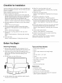
Removing Packaging
1. Remove filter, accessories and hardware. Do not
remove the Styrofoam protecting the front of the oven.
2. Fold back all four carton flaps fully against carton
sides. Then carefully roll the oven and carton over onto
the top side. The oven should be resting in the
Styrofoam.
3. Pull the carton up and off the oven.
\ /I
\ I
\ t
4. Cut the middle of the outer protective plastic bag to
remove the mounting plate.
Tools and Parts Needed
o Philips head screwdriver
o Pencil
o Ruler or tape measure and straight edge
o Drill
o Drill bits: 3/16", 1/2", 5/8"
o Gloves
o Saw (saber, hole or keyhole)
o Stud finder or hammer
o Safety goggles
o Level
o Duct and masking tape
Optional tools
o Carpenter square
o Tin snips (to cut damper)
o Scissors (to cut cabinet template)
o Filler blocks or scrap wood pieces (for recessed
bottom cabinet installations)

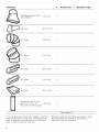
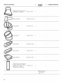
Parts Included
A B C D
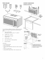
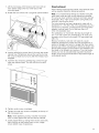
Location requirements
Installation dimensions
E F
i 13%"
(349mm)
min.
You will find the installation hardware contained in packet
with the unit. Check to make sure you have all these
parts:
A
B
C
D
E
F
Top mounting bolts:
Self-aligning machine screws 14"- 28x31/4 ''
Toggle bolts - 3/1 6"x3"
Wall mounting hardware:
Toggle wings
Wood screws 1/4"x2"
Nylon grommet (for metal cabinets)
Exhaust adaptor
Not shown:
o Top cabinet template
o Rear wall template
o Mounting plate (attached to the back of the microwave
oven)
o Aluminum grease filters
o Charcoal filter (factory fitted in the microwave oven)
min.12" (305mm)
max.14" (356mm)
min.66" _
(1676mm)_
........min. 16 1/2"
(419mm)
* min. 30"
(762mm)
For optimal performance and
reliability, the manufacturer
recommends 33"-36" clearance,
although the minimum allowable
clearance is noted 30".

Appliance dimensions
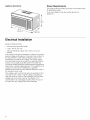
Power Requirements
The outlet must be properly grounded in accordance with
all applicable codes.
It can be installed inside the cabinet above the
appliance.
(419 mm)
Electrical Installation
Electrical Requirements:
o a three prong grounded outlet
o 120 V, 60 Hz, AC only
o 20 Amp electrical supply with a fuse or a circuit
breaker
This product must be connected to a supply circuit of the
proper voltage and frequency. Wire size must conform to
the requirements of the National Electric Code or the
prevailing local code for this rating. The power supply
cord and plug should be brought to a separate 20-amp
branch circuit single grounded outlet. The outlet box
should be located inside the cabinet above the appliance
(see section Location Requirements). The outlet box and
supply circuit should be installed by a qualified
electrician and conform to the National Electrical Code or
the prevailing local code.
The voltage used must be the same as specified on this
microwave oven. Using a higher voltage is dangerous
and may result in a fire or oven damage. Using a lower
voltage will cause slow cooking. The dealer is not
responsible for any damages resulting from the use of
the oven with any voltage other than specified.

Install Appliance
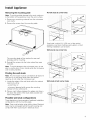
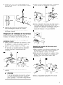
Removing the mounting plate
No wall studs at corner holes
Note: To avoid possible damage to the work surface or ___1
to the bottom of the appliance, cover the work surface.
1. Remove any remaining contents from the microwave i "-
oven cavity, i
2. Remove the screws from the mounting plate.
i ¸
The mounting plate will be used as the rear wall
template and for mounting.
3. Reinstall the screws into the holes where they were
removed.
Note: To avoid damage to the microwave oven, do not
grip or use the door or door handle while the microwave
oven is being handled.
Finding the wall studs
Note: The microwave must be connected to at least one
wall stud. If no wall studs exist within the cabinet
opening, do not install the microwave oven.
1. Locate the edges of the wall studs within the cabinet
opening by using:
- a stud finder or
- a hammer (tapping lightly across the mounting
surface to find a solid sound).
2. Place a mark halfway between the edges and draw a
line down the center of the studs (See possible wall
studs configuration).
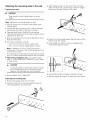
Possible wall stud configurations
These depictions show examples of preferred installation
configurations with the mounting plate.
Note: Care must be taken when drilling holes. Electrical
wires may be concealed behind the wall covering and
contact with them could result in electrical shock.
If wall stud is within 61/4'' (159 mm) of the vertical
centerline, only Room Venting (recirculation) or Roof
Venting installations can be done.
Wall stud at one corner hole
Wall studs at both corner holes
i
i
i

Attaching the mounting plate to the wall
Preparing rear wall
CAUTION
Wear gloves to avoid cutting fingers on sharp
edges.
Note: Make sure the cabinet bottom is level.
1. Draw a vertical line on the wall at the center of the
cabinet space.
2. Cabinet with front overhang: Draw a line on the back
wall equal to the depth of the front overhang.
3. Tape the REAR WALL TEMPLATE onto the wall
matching the centerline and touching the bottom of the
cabinet or the level line.
4. Draw a horizontal line on the wall at the bottom of the
Rear Wall Template.
5. Drill holes at locations A and B:
o 3/16" (5 mm) holes for wood screws (stud)
o 5/8" (16 mm) holes for toggle bolts (no stud)
Note: If neither A nor B is in a stud, find a stud
somewhere in the area of the mounting plate and drill
a 3/1 6" (5 mm) hole.
It is important to use at least one wood screw mounted
firmly in a stud to support the weight of the microwave.
6. Wall venting installation only: Cut out the shaded
area "F" on the REAR WALL TEMPLATE using a saber
or keyhole saw.
CAUTION
If exhaust adaptor is positioned outside consider
recommended dimensions, otherwise grease-
laden air will discharge into house structure.
7. Remove REAR WALL TEMPLATE.
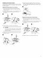
Attaching the mounting plate
1. Remove the toggle wings from the bolts.
2. Insert the bolts into the mounting plate through the
holes designated to go into drywall.
3. Attach toggle wings from the back of the mounting
plate onto each bolt. Leave enough space for toggle
wings to go through the wall and to open.
4. Place the mounting plate against the wall and push the
bolts through the drywall.
5. Finger tighten the bolts to make sure toggle wings
have opened against drywall.
t
l
6. Verify that the plate is properly centered and level.
7. Securely tighten all screws, including the wood screw.
10

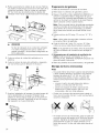
Adapting microwave blower
This microwave is shipped assembled for Room Venting
Installation. The blower unit is already in place and must
not to be adapted.
Adapting microwave blower for roof venting
1. Remove and save the screws holding the blower
motor and the blower plate. Lift up the blower plate
and put it aside.
2. Carefully pull out the blower unit and rotate 90 ° so that
fan blade openings are facing out the top of the
microwave.
3. Place the blower unit back into the opening.
CAUTION
Do not pull or stretch the blower unit wiring. Make
sure the wires are not pinched, and that they are
properly secured.
4. Replace the blower plate and secure with the screws
removed in step 1.
m
5. Attach the exhaust adapter to the top of the blower
plate by sliding it into the guides. Push in securely until
it is in the locking tabs. Make sure the damper hinge
swings freely.
1;t
Adapting microwave blower for wall venting
1. Remove and save the screws holding the blower
motor and the blower plate. Lift up the blower plate
and put it aside.
2. Carefully pull out the blower unit and rotate 90 ° so that
fan blade openings are facing out the top of the
microwave.
3. Rotate the blower unit counterclockwise 180 °.
11

4.Gentlyremovethewiresfromthegrooves.Reroutethe
wiresthroughthegroovesonothersideoftheblower
unit.Rotateblowerunit90°sothatfanbladeopenings
arefacingoutthebackofthemicrowave.
a! n
CAUTION
Do not pull or stretch the blower unit wiring. Make
sure the wires are not pinched, and that they are
properly secured.
5. Place the blower unit back into the opening.
6. Replace the blower plate and secure with the screws
removed in Step 1.
7. Attach the exhaust adapter to the rear of the oven by
sliding it into the guides. Push in securely until it is in
the lower locking tabs. Make sure the damper hinge
swings freely.
m
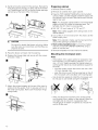
Preparing cabinet
1. Remove power to outlet.
2. Remove all contents from upper cabinet.
3. Tape the TOP CABINET TEMPLATE onto the bottom
surface. Make sure the template centerline aligns with
the vertical line on the wall. Rear wall arrows must be
against rear wall.
4=
=
Note: For recessed cabinet bottom, trim the template
edges so that it fits inside the recessed area. The
template has trim lines to use as guides.
Drill 3\8" (10 mm) holes at "A", "B" and "C".
Note: Wear safety goggles when drilling holes in the
cabinet bottom.
Cut out the 2" (51 mm) hole at "D". This hole is for the
power supply cord.
Note: If the cabinet is metal, use the nylon grommet
around the opening to protect the cord.
6. Roof venting installation only: Cut out the shaded
area "E" on the TOP CABINET TEMPLATE using a
saber or keyhole saw.
7. Remove templates from back wall and cabinet.
Mounting the microwave oven
Notes
o If the bottom of the upper cabinet is recessed or has
front overhang, you will need to prepare 2"x 2" (51
mm x 51 mm - depth equivalent to cabinet recess or
overhang) filler blocks to provide additional support for
the bolts:
o mark the center of each filler block and drill a 3\8"
(10 mm) diameter hole
o align filler blocks over the three openings on top of
the microwave oven and attach with masking tape
o Use at least two people to install the microwave oven.
Do not grip or use handle during the installation.
o When mounting the microwave oven, thread power
cord through hole in bottom of top cabinet. Keep the
cord tight and do not pinch it, especially when
mounting flush to bottom of cabinet. Do not pull the
cord to lift the oven.
12

1.Liftthemicrowave,tiltitforward,andhookslotsat
backbottomedgeontofourlowertabsofthe
mountingplate.
2.Rotatethefrontoftheovenupagainstcabinetbottom.
3.Insertaself-aligningscrew(itemA)throughtopcenter
cabinethole.Temporarilysecuretheovenbyturning
thescrewatleasttwofullturnsafterthethreadshave
engaged.
4.Insertthetworemainingself-aligningscrewsthrough
outertopcabinetholes.Turntwofullturnsoneach
screw.
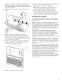
Hood exhaust
When venting exhaust to the outside, hood exhaust ducts
will be required. Read the following carefully.
Note: It is important that venting be installed using the
most direct route and with as few elbows as possible.
This ensures clear venting of exhaust and helps prevent
blockages. Also, make sure dampers swing freely and
nothing is blocking the ducts.
The hood exhaust has been designed to mate with a
standard 3t/2, x 10" (82 x 254 mm) rectangular duct. If a
round duct is required, a rectangular-to-round transition
adaptor must be used. Do not use less than a 6"
(152 mm) diameter duct.
For satisfactory air movement, the total duct length of
3t/4" x 10" (82 x 254 mm) rectangular or 6" (152 mm)
diameter round should not exceed 120 equivalent feet
(36.5 m).
Elbows, transitions, wall and roof caps etc. cause
additional resistance to airflow and are equivalent to a
section of straight duct which is longer than their actual
physical size. When calculating the total duct length, add
the equivalent lengths of all transitions and adaptors plus
the length of all straight duct sections. The chart below
shows you how to calculate total equivalent ductwork
length using the approximate feet of equivalent length of
some typical ducts:
5. Tighten center screw completely.
6. Tighten the outer two screws completely to the top of
the microwave oven.
Note: While tightening screws, hold the microwave
oven in place against the wall and the top cabinet.
7. Install grease filters by sliding them into the side slots,
then pushing up and toward oven to lock (image
shows bottom view of appliance).
13

Duct Pieces x Number used = Equivalent Length
Rectangular-to-Round Tran-
5 ft (1.5 m)
sition Adaptor*
X
Wall Cap 40 ft (12.2 m) x
90 ° Elbow 10 ft (3 m) x
45 ° Elbow 5 ft (1.5 m) x
90 ° Elbow 25 ft (7.6 m) x
45 ° Elbow 5 ft (1.5 m) x
Roof Cap 24 ft (7.3 m) x
Straight Duct 6" (152 mm
Round or 3 1/4"x 10" 1 ft (0.3 m)
(82 x 254 mm) Rectangular
X
Total Ductwork =
* If a rectangular-to-round transition adapter is used, first
make sure the damper hinge of the microwave swings
freely. If necessary, cut the damper to fit, using the tin
snips, in order to allow free movement.
Equivalent lengths of duct pieces are based on actual
tests and reflect requirements for good venting
performance with any vent hood.
14

::, _ ___ ..........................................................................
Testing Operation
1. Turn on power at the breaker.
2. Test the oven mode:
Test the CONVECTION oven mode (if available). See
the Use and Care Manual for detailed operation
instructions.
3. Verify that the oven light comes on and the oven
begins to preheat.
4. Test the microwave:
Place a cup of water into the oven cavity. Follow the
instructions in the Use and Care Manual on how to
heat a beverage.
5. Verify that the oven light comes on and the water is
heated.
6. If any of the tests do not result as explained above,
contact service for assistance. Otherwise, the
installation is complete at this time.
Bosch®Support
Before Calling Service
See the Use and Care Manual for troubleshooting
information. Refer to the Warranty in the Use and Care
Manual.
To reach a service representative, see the contact
information at the front of the manual. Please be
prepared with the information printed on your product
data plate when calling.
Data Plate
The data plate shows the model and serial number. Refer
to the data plate on the appliance when requesting
service.
The data plate can be found on the inside of the
appliance.
Service
We realize that you have made a considerable
investment in your kitchen. We are dedicated to
supporting you and your appliance so that you have
many years of creative cooking.
Please don't hesitate to contact our Customer Support
Department if you have any questions or in the unlikely
event that your Bosch® appliance needs service. Our
service team is ready to assist you.
USA
800-944-2904
www.bosch-home.com/us/su pport
Canada
800-944-2904
www.bosch-home.ca/en/su pport
Parts and Accessories
Parts, filters, descalers, stainless steel cleaners and more
can be purchased in the Bosch ® eShop or by phone.
USA
www.bosch-home.com/us/store
Canada
Marcone 800-482-6022
or
Reliable Parts 800-941-9217
To avoid having to search for each piece of information
when calling, you can enter the four items needed in the
spaces provided below.
Model No.
FD-No.
Date of Purchase
Customer Service
Keep your invoice or escrow papers for warranty
validation if service is needed.
15

Contenido
Definiciones de Seguridad ......................................... 17
INSTRUCCIONES DE SEGURIDAD IMPORTANTES .. 18
Seguridad con el manejo del electrodomestico ......... 18
Codigos y normas de seguridad ................................... 18
Advertencias en virtud de la Proposicion 65
del estado de California ................................................... 18
Seguridad con la electricidad ......................................... 18
Seguridad con el microondas ........................................ 18
Seguridad relacionada con los equipos ....................... 19
Lista de verificacion de instalacion ........................... 20
Antes de empezar ........................................................ 20
Quitar el embalaje ............................................................. 20
Herramientas y piezas necesarias ................................. 21
Piezas incluidas ................................................................. 21
Requisitos de ubicacion .................................................. 21
Requisitos de electricidad ............................................... 22
Instalacion electrica .................................................... 22
Montaje del electrodomestico .................................... 23
Retiro de la placa de fijacion .......................................... 23
BOsqueda de los pasadores de pared ......................... 23
Posibles configuraciones de los pasadores
de pared ............................................................................. 23
Acoplamiento de la placa de fijacion a la pared ........ 24
Adaptacion del ventilador del microondas .................. 25
Preparacion del gabinete ................................................ 26
Montaje del horno microondas ...................................... 26
Escape de la campana .................................................... 27
Prueba del funcionamiento ........................................ 29
Soporte de Bosch ® ...................................................... 30
Antes de Ilamar al servicio ............................................ 30
Placa de datos .................................................................. 30
Servicio tecnico ................................................................. 30
Piezas y accesorios .......................................................... 30
z,Preguntas?
1-800-944-2904
www.bosch-home.com
1901 Main Street, Suite 600
Irvine, CA 92614
iCon gusto Io atenderemos!
16

Definiciones de Seguridad
ADVERTENCIA
Esto indica que se pueden producir lesiones graves
o la muerte si no se cumple con esta advertencia.
ATENCION
Esto indica que pueden producirse lesiones leves o
moderadas si no se cumple con esta advertencia.
AVISO: esto indica que puede producirse un da_o al
electrodomestico o a la propiedad como resultado de la
falta de cumplimiento de este aviso.
Nota: Esto Io alerta sobre informacion y/o consejos
importantes.
17

A
INSTRUCCIONES DE SEGURIDAD IMPORTANTES
LEA Y CONSERVE ESTAS INSTRUCCIONES
INSTALADOR: DEJE ESTAS INSTRUCCIONES CON EL
ELECTRODOMI_STICO CUANDO HAYA FINALIZADO LA
INSTALACI©N.
IMPORTANTE: CONSERVE ESTAS INSTRUCCIONES
PARA USO DEL INSPECTOR DE ELECTRtCIDAD
LOCAL.
ADVERTENCIA
Si no sigue la informaci6n de este manual exactamente,
se puede ocasionar un incendio o una descarga
el6ctrica que puede causar da_os materiales o lesiones
personales.
ADVERTENCIA
No repare ni reemplace ninguna parte del
electrodom6stico, a menos que este especfficamente
recomendado en este manual. Nunca modifique ni altere
la construcci6n del electrodom6stico. La instalaci6n,
servicio tecnico o mantenimiento incorrectos pueden
causar lesiones o da_os materiales. Consulte este
manual para su orientacion. Remita todas las
reparaciones a un centro de servicio tecnico autorizado
por la fa.brica.
Seguridad con el manejo del
electrodomestico
La unidad es pesada y se requieren al menos dos
personas o un equipo adecuado para trasladarla.
No levante el electrodom6stico toma.ndolo del asa de la
puerta.
Las superficies ocultas pueden tener bordes filosos.
Proceda con cuidado al intentar tomar el
electrodom6stico por la parte trasera o desde abajo.
Codigos y normas de seguridad
Este electrodomestico cumple con la Oltima version de
una o ma.s de las siguientes normas:
o CAN/CSA C22.2 No. 61 - Estufas de uso domestico
(Household Cooking Ranges)
o UL 858 - Estufas electricas de uso domestico
(Household Electric Ranges)
o CAN/CSA C22.2 N. ° 150 - Hornos de microondas
(Microwave Ovens)
o UL 923 - Electrodom6sticos de coccion por
microondas (Microwave Cooking Appliances)
o UL 507 - Ventiladores electricos (Electric Fans)
o CAN/CSA C22.2 No. 113 - Ventiladores (Fans and
Ventilators)
o CSA C22.2 N.° 64 - Electrodom6sticos para cocinar y
para calentar Ifquidos de uso domestico (Household
Cooking and Liquid-Heating Appliances)
o UL 1026 - Electrodom6sticos para cocinar y para
servir alimentos el6ctricos de uso domestico (Electric
Household Cooking and Food Serving Appliances)
Es responsabilidad del propietario y el instalador
determinar si se aplican otros requisitos y/o normas en
instalaciones especfficas.
Advertencias en virtud de la
Proposicion 65 del estado de California
ADVERTENCIA
Este producto contiene una o ma.s sustancias qufmicas
que el estado de California sabe que provocan ca.ncer,
defectos congenitos, u otro da_o reproductivo.
Seguridad con la electricidad
ADVERTENCIA
Antes de enchufar un cable electrico o apagar la fuente
de alimentaci6n el6ctrica, asegOrese de que todos los
controles se encuentren en la posicion OFF (Apagado).
Para los electrodom6sticos equipados con cable y
enchufe, no corte ni retire la espiga de conexion a tierra.
Debe enchufarse en un recepta.culo de conexion a tierra
compatible para evitar descargas el6ctricas. Si tiene
alguna duda respecto de si el recepta.culo de pared esta.
correctamente conectado a tierra, el cliente debe
solicitar la verificacion de un electricista calificado.
Si el Codigo Nacional EI6ctrico (o el Codigo EI6ctrico
Canadiense) asf Io requiere, este electrodom6stico debe
instalarse en un circuito derivado por separado.
El instalador debe mostrar al propietario la ubicacion del
disyuntor o el fusible. Ma.rquela para recordarla ma.s
fa.cilmente.
Antes de realizar la instalaci6n, apague la alimentaci6n
electrica en el panel de servicio. Trabe el panel de
servicio para impedir que se encienda accidentalmente
la alimentaci6n electrica.
AsegOrese de que el electrodom6stico sea
correctamente instalado y conectado a tierra por un
tecnico calificado. La instalaci6n, las conexiones
el6ctricas y la conexion a tierra deben cumplir con todos
los codigos correspondientes.
Seguridad con el microondas
PRECAUCIONES QUE DEBE TENER EN CUENTA
ANTES DEL SERVICIO TECNICO Y DURANTE ESTE
PARA EVITAR LA POSIBLE EXPOSICI©N A UN EXCESO
DE ENERGfA DE MtCROONDAS
No maneje ni permita que se maneje el horno con la
puerta abierta.
Realice los siguientes controles de seguridad en
todos los hornos que necesitan servicio tecnico antes
de activar el magnetron u otra fuente de microondas,
y haga las reparaciones segOn corresponda:
18

A
INSTRUCCIONES DE SEGURIDAD IMPORTANTES
LEA Y CONSERVE ESTAS INSTRUCCIONES
1. Funcionamiento del enclavamiento
2. Cierre correcto de la puerta
3. Sellos y superficies sellantes (arcos el6ctricos,
desgaste y otros da_os)
4. Bisagras y trabas da_adas o sueltas
5. Evidencia de cafdas o abuso
o Antes de activar la alimentaci6n electrica del
microondas para realizar pruebas o inspecciones de
servicio tecnico en los compartimentos que generan
microondas, verifique el magnetron, la gufa de onda
luminosa o la Ifnea de transmision, y verifique que la
alineaci6n, la integridad y la conexion de la cavidad
sean correctas.
o Se deben reparar, reemplazar o ajustar todos los
componentes defectuosos o mal ajustados de los
sistemas de enclavamiento, monitoreo, sello de la
puerta y generacion y transmisi6n de microondas,
segOn los procedimientos descritos en este manual,
antes de devolver el horno a su propietario.
o Se debe realizar en cada horno un control de fugas de
microondas para verificar el cumplimiento con la
Norma de Rendimiento Federal (Federal Performance
Standard), antes de devolverlo a su propietario.
INSTRUCCIONES PARA LA CONEXt©N A TIERRA
Este aparato debe estar conectado a tierra. En caso de
un cortocircuito electrico, la conexion a tierra reduce el
riesgo de descarga el6ctrica proporcionando un cable
de escape para la corriente electrica.
Este aparato viene equipado con un cable que tiene un
alambre de conexion a tierra con un enchufe de
conexion a tierra. El enchufe debe colocarse en una
toma de corriente que este instalada y conectada a tierra
en forma adecuada.
ADVERTENCIA
A fin de reducir el riesgo de incendio, utilizar 0nicamente
conducciones de metal.
ATENCION
Solo para la ventilacion general. No utilizar para la
extraccion de sustancias y vapores peligrosos o
explosivos.
ADVERTENCIA
La incorrecta conexion a tierra puede provocar un riesgo
de descarga el6ctrica. Consulte a un electricista
calificado si no comprende la totalidad de las
instrucciones de conexion a tierra o si tiene alguna duda
respecto de si el aparato esta. correctamente conectado
a tierra. No use un cable de extensi6n. Si el cable de
alimentaci6n el6ctrica es demasiado corto, solicite a un
electricista calificado que instale una toma de corriente
cerca del aparato.
Seguridad relacionada con los equipos
Retire toda la cinta y el embalaje antes de usar el
electrodom6stico. Destruya el embalaje despues de
desembalar el electrodom6stico. Nunca deje que los
ni_os jueguen con el material de embalaje.
Nunca modifique ni altere la construccion del
electrodomestico. Por ejemplo, no retire las patas
niveladoras, paneles, cubiertas para cables ni soportes/
tornillos antivuelco.
19

Lista de verificacion de instalacion
Use esta lista de verificacion para verificar que haya
completado cada paso del proceso de instalacion. Esta
lista puede ayudarlo a evitar errores comunes.
Consulte las instrucciones detalladas para cada paso en
las secciones que se encuentran a continuacion de esta
lista de verificacion.
1. Antes de instalar el aparato, asegOrese de verificar
que las medidas del gabinete sean correctas para su
aparato y que esten presentes las conexiones
electricas requeridas. AsegOrese de que el conducto
electrico proporcionado en el aparato pueda Ilegar al
punto de conexion.
Seccidn: Requisitos de ubicacidn
2. Mueva el aparato a su lugar, en frente de la abertura
del gabinete.
Seccidn: Retiro del embalaje
3. Retire los materiales de embalaje, pero deje el
embalaje de la parte inferior en el aparato para evitar
da_os al piso.
Seccidn: Retiro del embalaje
4. Retire la placa de fijacion de la parte posterior del
aparato.
Seccidn: Montaje del electrodomestico - Retiro de la
placa de fijacidn
5. Busque los pasadores de pared.
Seccidn: Montaje del electrodomestico - BOsqueda de
los pasadores de pared
6. Acople la placa de fijacion a la pared.
Seccidn: Montaje del electrodomestico -
Acoplamiento de la placa de fijacidn a la pared
7. Adapte el ventilador del microondas.
Seccidn: Montaje del electrodomestico - Adaptacidn
del ventilador del microondas
8. Prepare el gabinete para la installaci6n del aparato.
Seccidn: Montaje del electrodomestico - Preparacidn
de/gabinete
9. Con ayuda, levante el aparato; inclinelo hacia adelante
y enganche los slots en la placa de fijacion.
Seccidn: Montaje del electrodomestico - Montaje del
homo microondas
10. Deslice completamente el aparato en su lugar y
sujete el aparato en la abertura del gabinete con los
tornillos suministrados.
Seccidn: Montaje del electrodomestico - Montaje del
homo microondas
11. Use el conducto correcto para escape de la
campana.
Seccidn: Montaje del electrodomestico - Escape de la
campana
12. AsegOrese de que el aparato funciona.
Seccidn: Prueba de/funcionamiento
Lea y siga siempre las instrucciones de instalaci6n
completas incluidas en este manual.
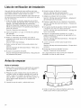
Antes de empezar
Quitar el embalaje
1. Retire el filtro, los accesorios y elementos de sujecion.
No retire el material de Styrofoam que protege el
frente del horno.
2. Pliegue las cuatro solapas de la caja de carton por
completo contra las paredes laterales de la caja de
carton. Luego, con cuidado, de vuelta el horno y la
caja de carton, y apoyelos sobre la parte superior. El
horno deberfa estar apoyado en el material de
Styrofoam.
3. Levante la caja de carton y refirela del horno.
\ /
\ I
\ I
4. Corte el medio de la bolsa protectora externa de
pla.stico para retirar la placa de fijacion.
20

Herramientas y piezas necesarias
o Destornillador con cabeza Phillips
o La.piz.
o Regla o cinta metrica, y borde recto.
o Taladro.
o Brocas: 3/16 pulg., 1/2 pulg., 5/8 pulg.
o Guantes.
o Sierra (de vaiven, de perforacion o de punta).
o Buscapasadores o martillo.
o Gafas de seguridad.
o Nivel
o Cinta de tela y de enmascarar.
Herramientas opcionales
o Escuadra de carpintero.
o Tijeras de hojalatero (para cortar el regulador).
o Tijeras (para cortar la plantilla de gabinetes)
o BIoques de relleno o piezas de trocerfa de madera
(para instalaciones de gabinetes inferiores
empotrados).
Piezas incluidas
B C D
E F
El soporte para la instalacion se encuentra en el paquete
junto con la unidad. Asegurarse de que todas estas
partes esta.n incluidas:
A
Pernos de montaje superiores:
Tornillos autoalineables para metales 1/4"-
28x31/4''
B Tornillos basculantes - 3/1 6"x3"
C
Soporte para montaje en pared:
Anclajes de mariposa
D Tornillos para madera 1/4"x2"
E Pasacables de nailon (para armarios de metal)
F Pieza de conexion para ventilacion
No mostrados:
° Plantilla para armario superior
° Plantilla para pared trasera
° Placa de fijacion (unida a la parte posterior del horno
de microondas)
° Filtros antigrasa de aluminio
° Filtro de carb6n activo (instalado de fa.brica en el
homo de microondas)
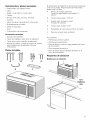
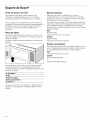
Requisitos de ubicacion
Medidas para la instalacion
i 13¾"
(349mm)
rain.
21

Medidas del aparato
min.12" (305mm)
max.14" (356mm)
min. 16 1/2"
(419m m)
* min. 30"
(762mm)
min. 66" _
(1676mm)_
'''----_C) * Para obtener rendimiento y
fiabilidad 6ptimos, el fabricante
recomienda de 33" a 36" de
I I| _ distancia, a pesar de la distancia
_::::__ I minima permitida se Observ6 30'''
16 /2"
(419 mm)
29 7/8"
(760 mm)_.._ 319503/8''mm)
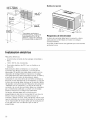
Requisitos de electricidad
La toma de corriente debe tener la conexion a tierra
adecuada de conformidad con todos los codigos
correspondientes.
Se puede instalar dentro del gabinete que se encuentra
arriba del horno.
Instalacion electrica
Requisitos electricos:
o Una toma de corriente de tres espigas conectada a
tierra.
o 120 V, 60 Hz, CA Onicamente.
o Suministro electrico de 20 A con un fusible o un
disyuntor.
Este producto debe conectarse a un circuito de
suministro que tenga una tension y una frecuencia
adecuadas. El tama_o del cable debe cumplir con los
requisitos del Codigo Electrico Nacional o el codigo
local pertinente para esta capacidad nominal. El cable y
el enchufe de suministro de alimentaci6n deben
colocarse en una Onica toma de corriente conectada a
tierra de circuito derivado de 20 A separada. La caja de
la toma de corriente debe ubicarse en la seccion detra.s
del aparato (consulte la seccion Requisitos de ubicacidn
- Medidas para la instalacidn). La caja de la toma de
corriente y el circuito de suministro deben ser instalados
por un electricista calificado y cumplir con el Codigo
Electrico Nacional o el c6digo local pertinente.
La tension utilizada debe ser la misma que la
especificada en este horno microondas. El uso de una
tensi6n mayor es peligroso y puede provocar un
incendio o daSos al horno. Usar una tension menor hara.
que los alimentos se cocinen lentamente. El comerciante
no es responsable de ningOn daSo que se produzca por
el uso del horno con una tension que no sea la
especificada.
22

Montaje del electrodomestico
Retiro de la placa de fijacion
Nota: Para evitar posibles dar_os a la superficie de
trabajo o a la parte inferior del aparato, cubra la
superficie de trabajo.
1. Retire cualquier elemento que haya quedado en la
cavidad del horno microondas.
2. Retire los tornillos de la placa de fijaci6n.
/
i ¸¸
i_ ii ii i
La placa de fijaci6n se utilizara, como plantilla de la
pared trasera y para el montaje.
3. Reinstale los tornillos en los orificios de los que fueron
retirados.
Nota: Para evitar dar_ar el horno microondas, no sujete
ni use la puerta ni la manija de la puerta mientras esta.
manejando el homo microondas.
Busqueda de los pasadores de pared
Nota: El microondas debe conectarse a, al menos, un
pasador de pared. Si no hay pasadores de pared en la
abertura del gabinete, no instale el horno microondas.
1. Ubique los bordes de los pasadores de pared dentro
de la abertura del gabinete utilizando Io siguiente:
- un buscapasadores; o bien
- un martillo (golpeando levemente la superficie de
montaje para encontrar un sonido s61ido).
2. Coloque una marca en la mitad entre los bordes y
dibuje una linea por el centro de los pasadores
(consulte la posible configuracion de los pasadores
de pared).
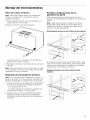
Posibles configuraciones de los
pasadores de pared
Estas representaciones muestran ejemplos de las
configuraciones preferidas de instalaci6n con la placa de
fijacion.
Nota: Debe tenerse cuidado al taladrar los orificios.
Puede haber cables el6ctricos ocultos detra.s de la
cubierta de la pared y el contacto con estos podrfa
provocar una descarga electrica.
Sin pasadores de pared en los orificios de las esquinas
Si el pasador de pared se encuentra dentro de 61/4pulg.
(1 59 mm) de la linea central vertical, 0nicamente pueden
realizarse las instalaciones de ventilaci6n de ambiente
(recirculacion) o de ventilacion de techo.
Pasador de pared en uno de los orificios de las
esquinas
23

Pasadores de pared en ambos orificios de las
esquinas
Acoplamiento de la placa de fijacion a
la pared
Preparacion de la pared trasera
ATENCION
Utilice guantes para evitar cortarse los dedos en
bordes filosos.
Nota: AsegOrese de que la parte inferior del gabinete
este nivelada.
1. Dibuje una linea vertical en la pared en el centro del
espacio del gabinete.
2. Gabinete con voladizo delantero: dibuje una linea en
la pared trasera igual a la profundidad del voladizo
delantero.
3. Pegue la PLANTILLA DE LA PARED TRASERA con
cinta en la pared de modo que coincida con la linea
central y este en contacto con la parte inferior del
gabinete o la linea de nivel.
4. Dibuje una linea horizontal en la pared en la parte
inferior de la plantilla de la pared trasera.
5. Taladre orificios en los lugares A y B:
o Orificios de 3/16 pulg. (5 mm) para los tornillos
para madera (pasador).
o Orificios de 5/8 pulg. (16 mm) para los pernos de
anclaje (sin pasador).
Nota: Si ni A ni B se encuentran en un pasador,
encuentre un pasador en alguna parte de la seccion
de la placa de fijacion y taladre un orificio de 3/
16 pulg. (5 mm).
Es importante utilizar, como mfnimo, un tornillo para
madera montado firmemente en un pasador para
sostener el peso del microondas.
6. Unicamente para la instalacion de ventilacion de
pared: Corte la seccion sombreada "F" en la
PLANTILLA DE LA PARED TRASERA utilizando una
sierra de vaiven o de punta.
ATENCION
Si el adaptador de escape esta. ubicado en el
exterior, considere las medidas recomendadas;
de Io contrario, el aire con grasa se descargara.
hacia la estructura del hogar.
7. Retire la PLANTILLA DE LA PARED TRASERA.
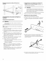
Acoplamiento de la placa de fijacion
1. Retire las alas de anclaje de los pernos.
2. Inserte los pernos en la placa de fijacion a traves de
los orificios designados para atravesar el panel de
yeso.
3. Acople las alas de anclaje de la parte trasera de la
placa de fijacion en cada perno. Deje espacio
suficiente para que las alas de anclaje atraviesen la
pared y se abran.
O
O
4. Coloque la placa de fijacion contra la pared y empuje
los pernos a traves del panel de yeso.
24

5.Ajusteconlamanolospernosparaasegurarsede
quelasalasdeanclajedesehayanabiertocontrael
paneldeyeso.
t
////
////
////
////
////
I///
////
////
////
6. Verifique que la placa este centrada en forma
adecuada; asegOrese de que este nivelada.
7. Ajuste firmemente todos los tornillos, incluido el
tornillo para madera.
Adaptacion del ventilador del microondas
Este microondas se envfa ensamblado para la
instalaci6n de ventilaci6n de ambiente. La unidad del
ventilador ya esta. en su lugar y no debe adaptarse.
Adaptacion del ventilador del microondas para la
ventilacion de techo
1. Retire y conserve los tornillos que sostienen el motor
del ventilador y la placa del ventilador. Levante la
placa del ventilador y dejela a un costado.
2. Retire la unidad del ventilador con cuidado y rotela
90 ° de modo que las aberturas de los a.labes del
ventilador miren hacia la parte superior del
microondas.
3.Vuelva a colocar la unidad del ventilador en la
abertura.
ATENCION
No tire del cableado de la unidad del ventilador
ni Io estire. AsegOrese de que los cables no
queden pinzados y de que esten asegurados en
forma adecuada.
4. Vuelva a colocar la placa del ventilador y asegOrela
con los tornillos que se retiraron en el paso 1.
m
5. Acople el adaptador del escape a la parte superior de
la placa del ventilador desliza.ndolo en las guias.
EmpOjelo hacia adentro en forma segura hasta que se
encuentre en los fijadores. AsegOrese de que la
bisagra del regulador se mueva libremente.
m
Adaptacion del ventilador del microondas para la
ventilacion de pared
1. Retire y conserve los tornillos que sostienen el motor
del ventilador y la placa del ventilador. Levante la
placa del ventilador y dejela a un costado.
2. Retire la unidad del ventilador con cuidado y rotela
90 ° de modo que las aberturas de los a.labes del
ventilador miren hacia la parte superior del
microondas.
3.Rote la unidad del ventilador 180 ° en el sentido
contrario alas agujas del reloj.
25

4.Retiresuavementeloscablesdelasranuras.Redirija
loscablesatravesdelasranurasenelotroladodela
unidaddelventilador.Rotelaunidaddelventilador
90° de modoquelasaberturasdelosa.labesdel
ventiladormirenhacialapartetraseradelmicroondas.
a! n
_i, ATENClON
No tire del cableado de la unidad del ventilador
ni Io estire. AsegOrese de que los cables no
queden pinzados y de que esten asegurados en
forma adecuada.
5. Vuelva a colocar la unidad del ventilador en la
abertura.
6. Vuelva a colocar la placa del ventilador y asegOrela
con los tornillos que se retiraron en el paso 1.
[] []
7. Acople el adaptador del escape a la parte trasera del
horno desliza.ndolo en las guias. EmpOjelo hacia
adentro en forma segura hasta que se encuentre en
los fijadores inferiores. AsegOrese de que la bisagra
del regulador se mueva libremente.
Preparacion del gabinete
1. Retire la alimentaci6n a la toma de corriente.
,
3.
4,
,
Retire todo el contenido del gabinete superior.
Pegue la PLANTILLA DEL GABtNETE SUPERIOR con
cinta en la superficie inferior. AsegOrese de que la
linea central de la plantilla este alineada con la linea
vertical en la pared. Las flechas de la pared trasera
deben ubicarse contra la pared trasera.
Nota" Para una parte inferior del gabinete empotrada,
recorte los bordes de la plantilla de modo que esta
calce dentro de la seccion empotrada. La plantilla
tiene lineas para recortar que puede utilizar como
guia.
Taladre orificios de 3\8 pulg. (1 0 mm) en "A", "B" y
Nota: Utilice gafas de seguridad al taladrar orificios
en la parte inferior del gabinete.
Corte el orificio de 2 pulg. (51 mm) en "D". Este
orificio es para el cable de alimentaci6n electrica.
Nota: Si el gabinete es de metal, utilice el pasacables
de nailon alrededor de la abertura para proteger el
cable.
6. Unicamente para la instalacion de ventilacion de
techo: Corte la seccion sombreada "E" en la
PLANTILLA DEL GABINETE SUPERIOR utilizando una
sierra de vaiven o de punta.
7. Retire las plantillas de la pared trasera y del gabinete.
Montaje del horno microondas
Notas
o Si la parte inferior del armario superior esta. empotrada
o tiene saliente delantero, se tendra.n que preparar
bloques de relleno de 2"x 2" (51 mm x 51 mm -
profundidad equivalente al hueco o saliente del
armario) para proporcionar apoyo adicional a los
pernos:
o marcar el centro de cada bloque de relleno y
perforar un orificio de 3\8" (10 mm)
o alinear los bloques de relleno sobre las tres
aberturas en la parte superior del horno de
microondas y fijar con cinta adhesiva
o Contar con al menos dos personas para instalar el
horno de microondas. No asir ni usar la empur_adura
durante la instalaci6n.
o AI montar el horno de microondas, pasar el cable de
corriente a traves del agujero en el fondo del armario
superior. Mantener el cable tenso y no aprisionarlo,
especialmente cuando se instale alineado con el
fondo del armario. No tirar del cable para levantar el
horno.
26

1.Levantarelhornodemicroondas,inclinarlohacia
adelanteyengancharlasranurasdelextremoinferior
delaparteposteriorenlascuatrolengOetasinferiores
delaplacadefijacion.
2.Girarlapartefrontaldelhornohaciaelfondodel
armario.
3.Insertaruntornilloautoalineable(objetoA)enel
agujerodelapartesuperiorcentraldelarmario.
Asegurarel hornotemporalmentegirandoeltornillo
porIomenosdosvueltascompletasdespuesdeque
suscuerdashayanencajado.
4.Insertarlosdostornillosautoalineablesrestantesen
losagujerosexterioresdelarmariosuperior.Girar
cadatornillodosvueltascompletas.
6.Apretarlosdostornillosexterioresporcompletoala
partesuperiordelhornodemicroondas.
Nota:Mientrasseaprietanlostornillos,sujetarel
homodemicroondasenellugarenelquese
colocara,contralaparedyel armariosuperior.
7.Colocarlosfiltrosantigrasainserta.ndolosenlas
ranuraslateralesy,a continuacion,empujandohacia
arribayhaciaelhornoparabloquearlos(laimagen
muestraunavistadelaparteinferiordelaparato).
Escape de la campana
Para ventilar aire de escape al exterior, se requieren
conductos de escape de la campana. Lea Io siguiente
con cuidado.
Nota: Es importante instalar la ventilaci6n utilizando la
ruta ma.s directa y con la menor cantidad posible de
codos. Esto garantiza una ventilaci6n del aire de escape
sin obsta.culos y ayuda a evitar obstrucciones. Adema.s,
asegOrese de que los reguladores se muevan con
libertad y de que no haya ningOn elemento bloqueando
los conductos.
El escape de la campana ha sido dise_ado para
acoplarse con un conducto rectangular esta.ndar de
31/4pulg. x 10 pulg. (82 x 254 mm). Si se requiere un
conducto redondo, debe utilizarse un adaptador para la
transici6n de rectangular a redonda. No utilice
conductos que tengan un dia.metro de menos de 6 pulg.
(152 mm).
Para el movimiento satisfactorio del aire, la Iongitud total
del conducto rectangular de 31/4pulg. x 10 pulg. (82 x
254 mm) o del conducto redondo de 6 pulg. (152 mm)
de dia.metro no debe superar el equivalente de 120 pies
(36.5 m).
Los codos, las transiciones, las tapas de pared y techo,
etc. provocan una resistencia adicional al flujo de aire y
son equivalentes a una secci6n de conducto recto de
mayor Iongitud que su tama_o fisico real. AI calcular la
Iongitud total del conducto, sume las longitudes
equivalentes de todas las transiciones y de todos los
adaptadores ma.s la Iongitud de todas las secciones de
conducto recto. El cuadro que se encuentra a
continuacion muestra c6mo calcular la Iongitud total
equivalente de la red de conductos utilizando la cantidad
de pies aproximada de Iongitud equivalente de algunos
conductos fipicos:
5. Apretar el tornillo central por completo.
27

Piezas de conductos x Cantidad = Longitud equivalente
utilizada
Adaptador de transicion de
5 pies (1.5 m)
rectangular a redonda*
X
Tapa
de pared 40 pies (12.2 m) x
Codo de 90 °
10 pies (3 m) x
Codo de 45 °
5 pies (1.5 m) x
Codo de 90 °
25 pies (7.6 m) x
Codo de 45 °
5 pies (1.5 m) x
Tapa de techo 24 pies (7.3 m) x
Conducto recto redondo de
6 pulg. (152 mm) o rectan-
gular de 3 1/4 pulg. x
10 pulg. (82 x 254 mm)
1 pie (0.3 m) x
Total de la red =
de conduc-
tos
28

*Siseutilizaunadaptadordetransici6nderectangular
aredonda,primeroasegOresedequelabisagradel
reguladordelmicroondassemuevaconlibertad.Deser
necesario,corteelregularparaquecalce,utilizandolas
tijerasdehojalatero,afindepermitirunmovimientocon
libertad.
Laslongitudesequivalentesde laspiezasdeconductos
sebasanenpruebasrealesyreflejanlosrequisitospara
obtenerunbuenrendimientodeventilaci6ncon
cualquiercampanadeventilaci6n.
Prueba del funcionamiento
1. Encienda la alimentaci6n electrica desde el disyuntor.
2. Pruebe el modo del horno:
Pruebe el modo del horno CONVECTION
(Conveccion) (siesta. disponible).Consulte el Manual
de uso y cuidado para obtener instrucciones de uso
detalladas.
3. Verifique que la luz del horno se encienda y que el
horno comience a precalentarse.
4. Pruebe el microondas:
Coloque una taza de agua en la cavidad del
horno.Siga las instrucciones que se indican en el
Manual de uso y cuidado sobre como calentar una
bebida.
5. Verifique que la luz del horno se encienda y que el
agua se caliente.
6. Si alguna de las pruebas no funciona segOn se explic6
anteriormente, comunfquese con el servicio tecnico
para obtener asistencia.De Io contrario, la instalaci6n
finaliza en este momento.
29

Soporte de Bosch®
Antes de Ilamar al servicio
Para obtener informacion sobre resoluci6n de
problemas, consulte el Manual de uso y cuidado.
Consulte la garanfia en el Manual de uso y cuidado.
Para consultar a un representante de servicio tecnico,
remftase a la informacion de contacto que aparece en el
frente del manual. Cuando Ilame, tenga a la mano la
informacion impresa en la placa de datos de su
producto.
Placa de datos
La placa de datos muestra el modelo y el nOmero de
serie. AI solicitar servicio tecnico, consulte la placa de
datos del aparato.
La placa de datos puede encontrarse en el interior del
aparato.
Servicio tecnico
Sabemos que usted ha realizado una inversion
considerable en su cocina. Nos dedicamos a brindar
asistencia a usted y a su aparato de manera que tenga
muchos a_os de cocina creativa.
No dude en comunicarse con nuestro Departamento de
Atencion al Cliente si tiene alguna pregunta o en el caso
poco probable de que su aparato Bosch® necesite
servicio tecnico. Nuestro equipo de servicio tecnico esta.
listo para asistirlo.
EUA
800-944-2904
www.bosch-home.com/us/su pport
Canada
800-944-2904
www.bosch-home.ca/en/su pport
Piezas y accesorios
Puede comprar piezas, filtros, productos para eliminar el
sarro, limpiadores para acero inoxidable y ma.s arficulos
en la tienda electronica de Bosch ® o por telefono.
I=UA
www.bosch-home.com/us/store
Canada
Marcone 800-482-6022
o
Reliable Parts 800-941-9217
Para evitar tener que buscar los datos de su aparato
cuando los precise, es aconsejable anotarlos aqui
conjuntamente con el nOmero de telefono del Servicio de
atencion al cliente:
N° de modelo
N° FD
Fecha de compra
Servicio de atencion
al cliente
Conserve su factura o los papeles de deposito para la
validacion de la garanfia si necesita solicitar servicio
tecnico.
30

BOSCH
9000927819 1901 Main Street, Suite 600 • Irvine, CA 92614 • 800-944-2904
931217 www.bosch-home.com ° (c_2012 BSH Home Appliances
-
 1
1
-
 2
2
-
 3
3
-
 4
4
-
 5
5
-
 6
6
-
 7
7
-
 8
8
-
 9
9
-
 10
10
-
 11
11
-
 12
12
-
 13
13
-
 14
14
-
 15
15
-
 16
16
-
 17
17
-
 18
18
-
 19
19
-
 20
20
-
 21
21
-
 22
22
-
 23
23
-
 24
24
-
 25
25
-
 26
26
-
 27
27
-
 28
28
-
 29
29
-
 30
30
-
 31
31


Bosch HMV5052U/02 Guía de instalación
- Categoría
- Microondas
- Tipo
- Guía de instalación
- Este manual también es adecuado para
en otros idiomas
- English: Bosch HMV5052U/02 Installation guide