Better Homes and Gardens BH18-084-097-26 Assembly Instructions Manual
- Categoría
- Muebles de bebe
- Tipo
- Assembly Instructions Manual
Este manual también es adecuado para

THIS INSTRUCTION BOOKLET CONTAINS IMPORTANT SAFETY INFORMATION.
PLEASE READ AND KEEP FOR FUTURE REFERENCE.
Date 2018-03-26 Rev. 0001-A Factory: JIYIFO
Kane Twin Loft Bed with Bookshelf
Stock # BH18-084-097-26 Mocha
# BH18-084-097-27 White
# BH18-084-097-28 Gray
ADULT ASSEMBLY REQUIRED
If you have any questions regarding assembly or if parts are missing, DO NOT return this item to the
store where it was purchased. Please call our customer service number and have your instructions
and parts list ready to provide the model name, part name or factory number:
866-942-5362
Pacific Standard Time: 8:30 a.m. - 4:30 p.m., Monday - Friday
Or visit our web site 24 hours a day, 7 days a week for product assistance at
www.whalenstyle.com
Or e-mail your request to parts@whalenfurniture.com
LOT NUMBER:
DATE PURCHASED: / /

2
ALWAYS USE GUARDRAILS ON BOTH LONG SIDES OF THE UPPER BUNK. IF
THE BUNK BED WILL BE PLACED NEXT TO THE WALL, THE GUARDRAIL
THAT RUNS THE FULL LENGTH OF THE BED SHOULD BE PLACED AGAINST
THE WALL TO PREVENT ENTRAPMENT BETWEEN THE BED AND WALL.
STRANGULATION HAZARD - Never attach or hang items to any part of the bunk bed
that are not designed for use with the bed; for example, but not limited to, hooks, belts,
and jump ropes.
Prohibit more than one person on upper bunk.
Maximum mattress thickness must not exceed 8 in. (20.32 cm). Surface of mattress must
be at least 5 in. (12.70 cm) below the upper edge of guardrails.
Use only mattress which is 74 in. (1.88 m) to 75 in. (1.90 m) long and 37 ½ in. (95.25 cm) to
38½ in. (97.79 cm) wide on upper bunk.
Replacement parts, including additional guardrails, may be obtained from any our dealer.

3
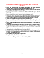
TO HELP PREVENT SERIOUS OR FATAL INJURIES FROM ENTRAPMENT
OR FALLS
• Follow the information on the warnings appearing on the upper bunk end
structure and on the carton. Do not remove warning label from bed.
• Always use the recommended size mattress or mattress support, or both, to help
prevent the likelihood of entrapment or falls.
• Surface of mattress must be at least 5 in. (12.70 cm) below the upper edge of
guardrails.
• Do not allow children under 6 years of age to use the upper bunk.
• Periodically check and ensure that the guardrail, ladder and other components
are in their proper position, free from damage and that all connectors are tight.
• Do not allow horseplay on or under the bed and prohibit jumping on the bed.
• Always use the ladder for entering and leaving the upper bunk.
• Do not use substitute parts. Contact the manufacturer or dealer for replacement
parts.
• Use of a night light may provide added safety precaution for a child using the
upper bunk.
• Always use guardrails on both long sides of the upper bunk. If the bunk bed will
be placed next to the wall, the guardrail that runs the full length of the bed
should be placed against the wall to prevent entrapment between the bed and
wall.
• The use of water or sleep flotation mattress is prohibited.
• STRANGULATION HAZARD – Never attach or hang items to any part of the
bunk bed that are not designed for use with the bed; for example, but not limited
to, hooks, belts, and jump ropes.
• Prohibit more than one person on upper bunk.
• Keep these instructions for future reference.
This product was manufactured April 2018.

4
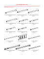
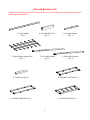
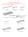
Parts and Hardware List
Please read completely through the instructions and verify that all listed parts and hardware are present
before beginning assembly.
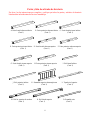
A- Lower Headboard Front Post B- Lower Headboard Back Post C- Lower Footboard Front Post
(Qty. 1) (Qty. 1) (Qty. 1)
D- Lower Footboard Back Post E- Upper Headboard Front Post F- Upper Headboard Back Post
(Qty. 1) (Qty. 1) (Qty. 1)
G- Upper Footboard Front Post H- Upper Footboard Back Post I- Lower Side Rail
(Qty. 1) (Qty. 1) (Qty. 2)
J- Lower Back Rail K- Upper Cross Assembly L- Upper Cap Rail
(Qty. 2) (Qty. 2) (Qty. 2)
M- Upper Ladder Side Rail N- Upper Mattress Side Rail O- Short Guardrail
(Qty. 1) (Qty. 1) (Qty. 2)

5
Parts and Hardware List
Please read completely through the instructions and verify that all listed parts and hardware are present
before beginning assembly.
P- Long Guardrail Q- Front Guardrail Post R- Guardrail Support
(Qty. 2) (Qty. 1) (Qty. 2)
S- Upper Mattress Support Slats T- Left Ladder Support U- Right Ladder Support
(Qty. 1) (Qty. 1) (Qty. 1)
V- Ladder Step (Qty. 4) W- Bookshelf Left Side (Qty. 1)
X- Bookshelf Right Side (Qty. 1) Y- Bookshelf Shelf (Qty. 4)

6
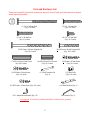
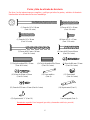
Parts and Hardware List
Please read completely through the instructions and verify that all listed parts and hardware are present
before beginning assembly.
(1) 1/4” x 100 mm Bolt (2) 1/4” x 45 mm Bolt
(Qty. 8+1 extra) (Qty. 8+1 extra)
(3) 1/4” x 38 mm Bolt (4) 1/4” x 15 mm Bolt
(Qty. 2+1 extra) (Qty. 32+1 extra)
(5) Ø6.5 mm x 100 mm Tapping Bolt (6) Ø6.5 mm x 48 mm Tapping Bolt
(Qty. 24+1 extra) (Qty. 20+1 extra)
(7) Ø10 x 50 mm Wood Dowel (8) Ø8 x 30 mm Wood Dowel (9) Ø4 mm x 35 mm S
crew
(Qty. 40+2 extra) (Qty. 16+1 extra) (Qty. 14+1 extra)
(10) Ø4 mm x 30 mm Screw (11) Bed Connector Pin (12) Barrel Nut
(Qty. 6+1 extra) (Qty. 4) (Qty. 8+1 extra)
(13) Ø3.5 mm x 19 mm Screw (Qty. 4+1 extra) (14) Metal Bracket (Qty. 1)
(15) L-shaped Metal Bracket (Qty. 16) Hex Wrench (Qty. 2)
Tools required: Hex wrench (provided) and Phillips screwdriver (not provided).

7
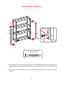
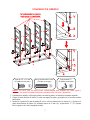
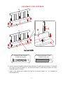
BOOKSHELF ASSEMBLY
NOTE: Please follow the instructions carefully to insure a safe and sturdy bed. Do not fully
tighten the bolts until all rails and guardrails are attached.
1. Unpack the units and confirm that you have all hardware and required parts.
2. Locate the Bookshelf Right Side (X) on a level and protected surface with the threaded inserts facing up.
3. Insert the 30 mm Wood Dowels (8) into the inner holes of the Shelves (Y) and attach them to the
Bookshelf Right Side (X) using the 15 mm Bolts (4) and the Metal Brackets (15). Securely tighten the
bolts with the enclosed hex wrench.
Ø8 x 30 mm Wood Dowel
(8 used in this step)
⑧
1/4” x 15 mm Bolt
(16 used in this step)
④
L-shaped Metal Bracket
(8 used in this step)
⑮

8
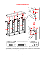
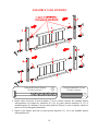
BOOKSHELF ASSEMBLY
4. Repeat the same procedure to attach the Bookshelf Left Side (W) at the opposite end.
5. Ask for assistance to lift the unit upright.
Ø8 x 30 mm Wood Dowel
(8 used in this step)
⑧
1/4” x 15 mm Bolt
(16 used in this step)
④
L-shaped Metal Bracket
(8 used in this step)
⑮

9
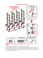
UPPER BUNK ASSEMBLY
6. Align and attach one Upper Cross Assembly (K) to one Upper Cap Rail (L) using two 50 mm Wood
Dowels (7) and three 48 mm Tapping Bolts (6). Securely tighten the bolts with the enclosed L-shaped
hex wrench.
7. Repeat the previous step to combine the remaining Upper Cap Rail (L) and Upper Cross Assembly (K)
together.
Ø10 x 50 mm Wood Dowel
(4 used in this step)
⑦
Ø6.5 mm x 48 mm Tapping Bolt
(6 used in this step)
⑥

10
UPPER BUNK ASSEMBLY
8. Insert four 50 mm Wood Dowels (7) into the end holes of the Upper Cross Assembly with warning
label (K). Attach the Upper Headboard Posts (E and F) to the Upper Cross Assembly (K) with four 100
mm Tapping Bolts (5) as shown. Tighten the bolts with the enclosed hex wrench.
9. Repeat the previous step to attach Upper Footboard Posts (G and H) to the other Upper Cross Assembly
(K).
Ø6.5 mm x 100 mm Tapping Bolt
(8 used in this step)
⑤
Ø10 x 50 mm Wood Dowel
(8 used in this step)
⑦

11
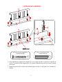
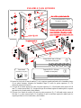
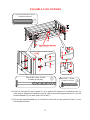
UPPER BUNK ASSEMBLY
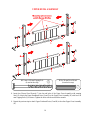
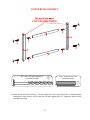
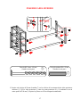
10. Insert the 50 mm Wood Dowels (7) into the drilled large holes of Long Guardrail (P) at both ends.
Attach two Long Guardrails (P) between the Upper Posts (F and H) with the100 mm Tapping Bolts (5).
11. Attach the Mattress Side Rail (N) between the Upper Posts (F and H) with four 100 mm Bolts (1) and
four Barrel Nuts (12). Make sure the wood stoppers for slats attached on side rail are up and face inward.
12. Attach the Ladder Side Rail (M) between the Upper Posts (E and G) using four 100 mm Bolts (1) and
four Barrel Nuts (12). Make sure the wood stoppers for slat attached on side rail are up and face inward.
Ø10 x 50 mm Wood Dowel
(4 used in this step)
⑦
Barrel Nut
(8 used in this step)
⑫
1/4” x 100 mm Bolt
(8 used in this step)
①
Ø6.5 mm x 100 mm Tapping Bolt
(4 used in this step)
⑤

12
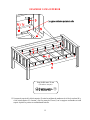
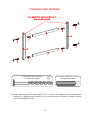
UPPER BUNK ASSEMBLY
13. Lay out the Upper Mattress Support Slats (S) between the wood stoppers on the Ladder Side Rail (M)
and the Upper Mattress Side Rail (N). Insert and screw 35 mm Screws (9) into the countersunk holes on
each slat. Tighten the screws using a Phillips screwdriver.
Ø4 mm x 35 mm Screw
(14 used in this step)
⑨

13
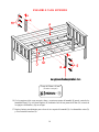
UPPER BUNK ASSEMBLY
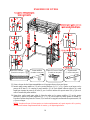
14. Insert the 50 mm Wood Dowels (7) into the end large holes of Short Guardrails (O) as a guide. Attach
two Short Guardrails (O) between the Upper Headboard Front Post (E) and Front Guardrail Post (Q)
with four 100 mm Tapping Bolts (5).
15. Fasten the Front Guardrail Post (Q) to the Ladder Side Rail (M) with two 38 mm Bolts (3), using the
enclosed hex wrench.
Ø1/4” x 38 mm Bolt
(2 used in this step)
③
Ø10 x 50 mm Wood Dowel
(4 used in this step)
⑦
Ø6.5 mm x 100 mm Tapping Bolt
(4 used in this step)
⑤

14
UPPER BUNK ASSEMBLY
16. With the pilot holes as a guide, align and attach one Guardrail Support (R) to the center of the Long
Guardrails (P) and the Upper Mattress Side Rail (N) by using three 30 mm Screws (10) through the
countersunk holes and screw into place.
17. Repeat the same procedure to attach the other Guardrail Support (R) to the Short Guardrails (O) and the
Ladder Side Rail (M).
Ø4 mm x 30 mm Screw
(6 used in this step)
⑩

15
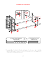
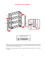
LOWER BUNK ASSEMBLY
18. Insert four 50 mm Wood Dowels (7) into the end holes of two Lower Side Rails (I) and attach them
between the Lower Posts (A and B) with four 100 mm Tapping Bolts (5). Tighten the bolts with the
enclosed hex wrench.
Ø6.5 mm x 100 mm Tapping Bolt
(4 used in this step)
⑤
Ø10 x 50 mm Wood Dowel
(4 used in this step)
⑦

16
LOWER BUNK ASSEMBLY
19. Align and attach the Lower Footboard Front Post (C) to the Bookshelf Left Side (W) by inserting the 48
mm Tapping Bolts (6) through the pre-drilled holes on the Bookshelf Left Side (W) and screw into the
post.
20. Attach the Lower Footboard Back Post (D) to the Bookshelf Right Side (X) with the 48 mm Tapping
Bolts (6).
Ø6.5 mm x 48 mm Tapping Bolt
(4 used in this step)
⑥

17
LOWER BUNK ASSEMBLY
21. Insert eight 50 mm Wood Dowels (7) into the end large holes of two Lower Back Rails (J). Attach the
Back Rails (J) between the Lower Back Posts (B and D) by using four 100 mm Tapping Bolts (5).
Tighten the bolts with the provided hex wrench.
Ø10 x 50 mm Wood Dowel
(8 used in this step)
⑦
Ø6.5 mm x 100 mm Tapping Bolt
(4 used in this step)
⑤

18
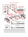
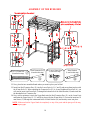
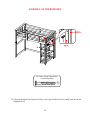
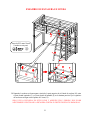
ASSEMBLY OF THE BUNK BED
22. Now, place the two assembled bunks where you want to place your loft bed.
23. Insert four Bed Connector Pins (11) into the Lower Posts (A, B, C and D) and secure them in place with
the 45 mm Bolts (2). When attaching the Connector Pin (11) to Lower Headboard Front Post (A), you
will need to insert one 45 mm Bolt (2) through the bottom hole of the Metal Bracket (14) and screw into
the threaded hole of Connector Pin.
24. Now, ask for assistance to stack the Upper Bunk onto the Bed Connector Pins (11) on the Lower Posts
and fasten the Upper Posts (E, F, G and H) in place with four 45 mm Bolts (2). Proceed to insert two 19
mm Screws (13) through the countersunk holes of Metal Bracket (14) and securely screw into place.
NOTE: Make sure that the Upper Bunk sits completely on top of the posts and the pins go all the way,
not leaving any gaps.
Ø1/4” x 45 mm Bolt
(8 used in this step)
②
Bed Connector Pin
(4 used in this step)
⑪
Metal Bracket
(1 used in this step)
⑭
Ø3.5 mm x 19 mm Screw
(2 used in this step)
⑬

19
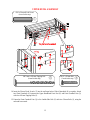
ASSEMBLY OF THE BUNK BED
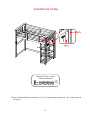
25. Fasten the Bookshelf Side Panels (W and X) to the Upper Footboard Posts (G and H) with two 48 mm
Tapping Bolts (6).
Ø6.5 mm x 48 mm Tapping Bolt
(2 used in this step)
⑥

20
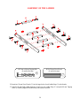
ASSEMBLY OF THE LADDER
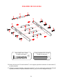
26. Insert two 50 mm Wood Dowels (7) into the large holes of each Ladder Steps (V) at both ends.
27. Attach Left and Right Ladder Supports (T and U) to the Ladder Steps (V) using the 48 mm Tapping
Bolts (6). Securely tighten all bolts with the enclosed hex wrench.
Ø6.5 mm x 48 mm Tapping Bolt
(8 used in this step)
⑥
Ø10 x 50 mm Wood Dowel
(8 used in this step)
⑦

21
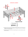
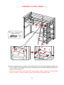
ASSEMBLY OF THE LADDER
28. Hook the Ladder securely over the top of the Ladder Side Rail (M), between the Upper Footboard Front
Post (G) and the Front Guardrail Post (Q) in the opening provided. Secure the Ladder Hooks in place by
using two 19 mm Screws (13).
ONLY USE LADDER IN THIS LOCATION AND SECURE WITH 2 SCREWS. PLEASE MAKE
SURE YOU INSTALL THE LADDER AGAINST THE FRONT GUARDRAIL POST.
Ø3.5 mm x 19 mm Screw
(2 used in this step)
⑬

22
Care and Maintenance
Use a soft, clean cloth that will not scratch the surface when dusting.
Use of furniture polish is not necessary. Should you choose to use polish, test first in an
inconspicuous area.
Using solvents of any kind on your furniture may damage the finish.
Never use water to clean your furniture as it may cause damage to the finish.
Always use coasters under beverage glasses and flowerpots.
Liquid spills should be removed immediately. Using a soft, clean cloth, blot the spill gently. Avoid
rubbing.
Always use protective pads under hot dishes and plates. Heat can cause chemical changes that may
create spotting within the furniture finish.
In the event that your furniture is stained or otherwise damaged during use, we recommend that
you call a professional to repair your furniture.
Check bolts/screws periodically and tighten them if necessary.
Further Advice about Wood Furniture Care
It is best to keep your furniture in a climate controlled environment. Extreme temperature and
humidity changes can cause warping, shrinking and splitting of wood. It is advised to keep furniture
away from direct sunlight as may damage the finish.
Proper care and cleaning at home will extend the life of your purchase. Following these important and
helpful tips will enhance your furniture as it ages.
We hope you enjoy your purchase for many years.
Thank you for your purchasing!
QUALITY GUARANTEE
We are confident that you will be delighted with your Whalen Furniture purchase.
Should this product be defective in workmanship or materials or fail under normal use, we will repair
or replace it for up to one (1) year from date of purchase. Every Whalen Furniture product is designed
to meet your highest expectations. We guarantee that you will immediately see the value of our fine
furniture.
This warranty gives you specific legal rights and you may also have other rights which vary from State
to State.
Customer Service: 866-942-5362
8:30 a.m. - 4:30 p.m., PST, Monday to Friday
www.whalenstyle.com

ESTE INSTRUCTIVO CONTIENE INFORMACION IMPORTANTE DE SEGURIDAD.
POR FAVOR LEA Y MANTENGA PARA USO FUTURO.
Fecha 2018-03-26 Rev. 0001-A Fábrica: JIYIFO
Cama superior individual con librero Kane
Serie #
BH18-084-097-26 Moca
# BH18-084-097-27 Blanco
# BH18-084-097-28 Gris
ENSAMBLE REQUERIDO POR
ADULTOS
Si tiene alguna pregunta relacionada con el montaje o si faltan piezas, NO devuelva este producto al
establecimiento donde lo adquirió. Por favor llame a nuestro número de servicio al cliente y tienen
sus instrucciones y lista de piezas listo para proporcionar el nombre del modelo, el nombre o el
número de parte de la fábrica:
866-942-5362
Hora estándar del Pacífico: 8:30 am - 4:30 pm, de Lunes - Viernes
O visite nuestro sitio web las 24 horas del día, 7 días a la semana para recibir asistencia del producto
en www.whalenstyle.com
O por correo electrónico su petición a parts@whalenfurniture.com
NÚMERO de LOTE:
FECHA de COMPRA: / /

2
UTILICE SIEMPRE LOS BARANDALES EN AMBOS LADOS LONGITUDINALES
DE LA LITERA SUPERIOR. SI VA A COLOCAR LAS LITERAS PEGADAS A LA
PARED, EL BARANDAL QUE CORRE A LO LARGO DE LA CAMA SE DEBE
COLOCAR CONTRA LA PARED PARA PREVENIR ENCIERROS ENTRE LA CAMA
Y LA PARED.
PELIGRO DE ESTRANGULACIÓN – Nunca coloque ni cuelgue cosas en alguna parte
de la litera que no estén diseñadas para usarse con la misma; por ejemplo, de manera
enunciativa, pero no limitativa, ganchos, cinturones o cuerdas para brincar.
Por seguridad solo una persona debe utilizar la litera superior.
El grosor máximo del colchón no debe exceder 8 pulgadas (20,32 cm). La superficie del
colchón debe estar, por lo menos, 5 pulgadas (12,70 cm) debajo de los barandales del
borde superior.
Utilice sólo colchón, que es de 74 pulgadas (1,88 m) a 75 pulgadas (1,90 m) de largo y 37 ½
pulgadas (95,25 cm) a 38½ pulgadas (97,79 cm) de ancho en la cama superior.
Las piezas de repuesto, incluyendo barandales adicionales, se pueden obtener de
cualquiera de nuestros distribuidores.

3
PARA AYUDAR A PREVENIR LESIONES GRAVES O MORTALES POR
ENCIERROS O CAÍDAS
• Siga la información de advertencia que aparece en la estructura extrema de la litera
superior y en la caja. No quite la etiqueta de advertencia de la cama.
• Use siempre el tamaño adecuado de soporte para el colchón para ayudar a prevenir
la posibilidad de encierro o caídas.
• La superficie del colchón debe ser de, por lo menos, 5 pulgadas (12,70 cm) abajo de
los barandales del borde superior.
• Nunca permita que un niño menor de 6 años de edad duerma en la litera superior.
• De manera periódica, revise y asegúrese de que el barandal, la escalera y otros
componentes estén en su posición correcta, libres de daños y que todos los
conectores estén apretados.
• No permita que los niños jueguen al caballito arriba o abajo de la cama y prohíbales
brincar sobre la misma.
• Siempre utilice la escalera para entrar y salir de la litera superior.
• No use partes sustitutas. Contacte al productor o distribuidor para obtener
repuestos.
• El uso de una lámpara de noche puede proveer mayor precaución de seguridad
para el niño que utilice la litera superior.
• Utilice siempre los barandales en ambos lados longitudinales de la litera superior.
Si va a colocar las literas pegadas a la pared, el barandal que corre a lo largo de la
cama se debe colocar contra la pared para prevenir encierros entre la cama y la
pared.
• No utilice colchones de agua o de flotación.
• PELIGRO DE ESTRANGULACIÓN – Nunca coloque ni cuelgue cosas en alguna
parte de la litera que no estén diseñadas para usarse con la misma; por ejemplo, de
manera enunciativa, pero no limitativa, ganchos, cinturones o cuerdas para brincar.
• Por seguridad solo una persona debe utilizar la litera superior.
•
Conserve estas instrucciones para referencias en el futuro
.
Este producto fue manufacturado en abril de 2018.

4
Partes y lista de artículos de ferretería
Por favor, lea las instrucciones por completo y verifique que todas las partes y artículos de ferretería
listadas estén incluidas antes de iniciar el ensamblaje.
A-Poste frontal cabecera inferior B- Poste posterior cabecera inferior C- Poste frontal piecera inferior
(Cant. 1) (Cant. 1) (Cant. 1)
D- Poste posterior piecera inferior E- Poste frontal cabecera superior F- Poste posterior cabecera superior
(Cant. 1) (Cant. 1) (Cant. 1)
G- Poste frontal piecera superior H- Poste posterior piecera superior I- Riel lateral inferior
(Cant. 1) (Cant. 1) (Cant. 2)
J- Riel posterior inferior K- Ensamble superior cabecera/piecera L- Tapa de riel superior
(Cant. 2) (Cant. 2) (Cant. 2)
M- Riel lat. superior de escalera N- Riel lateral superior O- Barandal corto
(Cant. 1) (Cant. 1) (Cant. 2)

5
Partes y lista de artículos de ferretería
Por favor, lea las instrucciones por completo y verifique que todas las partes y artículos de ferretería
listadas estén incluidas antes de iniciar el ensamblaje.
P- Barandal largo Q- Poste frontal de barandal R- Soporte de barandal
(Cant. 2) (Cant. 1) (Cant. 2)
S- Soporte de colchón superior T- Soporte de escalera izquierdo U- Soporte de escalera derecho
(Cant. 1) (Cant. 1) (Cant. 1)
V- Escalón (Cant. 4) W- Izquierdo de librero (Cant. 1)
X- Derecho de librero (Cant. 1) Y- Repisa librero (Cant. 4)

6
Partes y lista de artículos de ferretería
Por favor, lea las instrucciones por completo y verifique que todas las partes y artículos de ferretería
listadas estén incluidas antes de iniciar el ensamblaje.
(1) Perno de 1/4” x 100 mm (2) Perno de 1/4” x 45 mm
(Cant. 8+1 extra) (Cant. 8+1 extra)
(3) Perno de 1/4” x 38 mm (4) Perno de 1/4” x 15 mm
(Cant. 2+1 extra) (Cant. 32+1 extra)
(5) Perno de Ø6.5 mm x 100 mm (6) Perno de Ø6.5 mm x 48 mm
(Cant. 24+1 extra) (Cant. 20+1 extra)
(7) Clavija de madera Ø10 x 50 mm (8) Clavija de madera Ø8 x 30 mm (9) Perno de Ø4 mm
x 35 mm
(Cant. 40+2 extra) (Cant. 16+1 extra) (Cant. 14+1 extra)
(10) Perno de Ø4 mm x 30 mm (11) Perno metálico (12) Tuerca barril
(Cant. 6+1 extra) (Cant. 4) (Cant. 8+1 extra)
(13) Perno de Ø3.5 mm x 19 mm (Cant. 4+1 extra) (14) Soporte metal (Cant. 1)
(15) Soporte metal “L” (Cant. 16) Llave hexagonal (Cant. 2)
Herramienta requerida: Llave hexagonal (proveida) y desarmador estrella (no proveido).

7
ENSAMBLE DE LIBRERO
NOTA: Por favor, siga las instrucciones cuidadosamente para asegurar una cama segura y
resistente. No apriete los pernos hasta que se adjuntan todos los rieles y barandales.
1. Desempacar la unidad y verificar que cuenta con todas las partes y el material de ferreteria requerido.
2. Ubique el lateral derecho de librero (X) sobre una superficie plana y protegida con los insertos roscados
hacia arriba.
3. Inserte las clavijas de 30 mm de madera (8) en los orificios interiores de las repisas (Y) y fijarlas en el
panel lateral derecho de librero (X) utilizando pernos de 15 mm (4) y soporte metal “L” (15). Apriete
bien los pernos con la llave hexagonal incluida.
Clavija de madera Ø8 x 30 mm
(8 usados en este paso)
⑧
Perno de 1/4” x 15 mm
(16 usados en este paso)
④
Soporte metal “L”
(8 usados en este paso)
⑮

8
ENSAMBLE DE LIBRERO
4. Repita el mismo procedimiento para fijar el panel lateral izquierdo de librero (W) en el extremo opuesto.
5. Pida ayuda para levantar la unidad en posición vertical.
Clavija de madera Ø8 x 30 mm
(8 usados en este paso)
⑧
Perno de 1/4” x 15 mm
(16 usados en este paso)
④
Soporte metal “L”
(8 usados en este paso)
⑮

9
ENSAMBLE CAMA SUPERIOR
6. Alinee y conecte un ensamble superior de cabecera/piecera (K) a una tapa de riel superior (L) utilizando
dos clavijas de 50 mm de madera (7) y tres pernos de 48 mm (6). Apriete bien los pernos con la llave
hexagonal forma de L incluida.
7. Repita el paso anterior para combinar las tapas de riel superior restantes (L) y los ensambles de
cabecera/piecera (K).
Clavija de madera Ø10 x 50 mm
(4 usados en este paso)
⑦
Perno de Ø6.5 mm x 48 mm
(6 usados en este paso)
⑥

10
ENSAMBLE CAMA SUPERIOR
8. Inserte cuatro clavijas de 50 mm de madera (7) en los orificios extremos del ensamble superior
cabecera/piecera con etiqueta de advertencia (K). Fije los postes cabecera superiores (E y F) al
ensamble superior (K) mediante el uso de cuatro pernos de 100 mm (5) como se muestra. Apriete los
pernos con la llave hexagonal suministrada.
9. Repita el paso anterior para fijar los postes piecera superiores (G y H) al otro ensamble superior
cabecera/piecera (K).
Perno de Ø6.5 mm x 100 mm
(8
usados en este paso
)
⑤
Clavija de madera Ø10 x 50 mm
(8
usados en este paso
)
⑦

11
ENSAMBLE CAMA SUPERIOR
10. Inserte las clavijas de 50 mm de madera (7) en los agujeros grandes perforados de los barandales largos
(P) en ambos extremos. Adjuntar dos barandales largos (P) entre los postes superiores (F y H)
utilizando pernos de 100 mm (5).
11. Coloque un riel lateral superior (N) entre los postes superiores (F y H) utilizando cuatro pernos de 100
mm (1) y cuatro tuercas barril (12). Asegúrese de que las molduras esquina de madera para los soportes
que estan en el riel están arriba y hacia adentro.
12. Coloque el riel lateral de escalera (M) entre los postes superiores (E y G) utilizando cuatro pernos de
100 mm (1) y cuatro tuercas barril (12). Asegúrese de que las molduras esquina de madera para los
soportes que estan en el riel están arriba y hacia adentro.
Clavija de madera Ø10 x 50 mm
(4
usados en este paso
)
⑦
Tuerca barril
(4
usados en este paso
)
⑫
Perno de Ø1/4” x 100 mm
(8 usados en este paso)
①
Perno de Ø6.5 mm x 100 mm
(4 usados en este paso)
⑤

12
ENSAMBLE CAMA SUPERIOR
13. Descanse el soporte del colchón superior (S) entre las molduras de madera en el riel de la escalera (M) y
el riel lateral superior (N). Insertar y fijar los pernos de 35 mm (9) en los agujeros avellanados en cada
soporte. Apriete los pernos con un desarmador estrella.
Perno de Ø4 mm x 35 mm
(14
usados en este paso
)
⑨

13
ENSAMBLE CAMA SUPERIOR
14. Inserte las clavijas de 50 mm de madera (7) en los agujeros del extremo de los barandales cortos (O)
como una guía. Adjuntar dos barandales cortos (O) entre el poste frontal superior derecho (E) y el poste
frontal de barandal (Q) con cuatro pernos de 100 mm (5).
15. Fijar el poste frontal de barandal (Q) al riel lateral de escalera (M) con dos pernos de 38 mm (3), con la
llave hexagonal incluida.
Clavija de madera Ø10 x 50 mm
(4
usados en este paso
)
⑦
Perno Ø1/4” x 38 mm
(2
usados en este paso
)
③
Perno de Ø6.5 mm x 100 mm
(4 usados en este paso)
⑤

14
ENSAMBLE CAMA SUPERIOR
16. Con los agujeros piloto como una guía, alinee y conecte un soporte de barandal (R) para el centro de los
barandales largos (P) y riel lateral superior (N) mediante el uso de tres pernos de 30 mm (10) a través de
los agujeros avellanados y fije en su lugar.
17. Repita el mismo procedimiento para colocar el otro soporte de barandal (R) a los barandales cortos (O)
y el riel lateral de escalera (M).
Perno de Ø4 mm x 30 mm
(6
usados en este paso
)
⑩

15
ENSAMBLE AREA INFERIOR
18. Inserte cuatro clavijas de 50 mm de madera (7) en los orificios de los extremos de dos rieles laterales
inferiores (I) y adjuntarlos entre los postes (A y B) con cuatro pernos de 100 mm (5). Apriete los pernos
con la llave hexagonal incluida.
Perno de Ø6.5 mm x 100 mm
(4 usados en este paso)
⑤
Clavija de madera Ø10 x 50 mm
(4
usados en este paso
)
⑦

16
ENSAMBLE AREA INFERIOR
19. Alinear y colocar el poste frontal piecera inferior (C) al lateral izquierdo del librero (W) mediante la
inserción de pernos de 48 mm (6) a través de los agujeros previamente perforados en lateral izquierdo
del librero (W) y fije en su lugar en el poste.
20. Coloque al Poste posterior piecera inferior (D) para el lateral derecho del escritorio (X) con pernos de
48 mm (6).
Perno de Ø6.5 mm x 48 mm
(4 usados en este paso)
⑥

17
ENSAMBLE AREA INFERIOR
21. Inserte ocho clavijas de 50 mm de madera (7) en los orificios de los extremos de dos rieles posteriores
inferiores (J). Fije los rieles posteriores (J) entre los postes posteriores (B y D) mediante el uso de
cuatro pernos de 100 mm (5). Apriete los pernos con la llave hexagonal suministrada.
Clavija de madera Ø10 x 50 mm
(8
usados en este paso
)
⑦
Perno de Ø6.5 mm x 100 mm
(4 usados en este paso)
⑤

18
ENSAMBLE DE LITERA
22. Ahora, coloque las dos literas ensamblados en el lugar que desea colocar sus literas.
23. Inserte cuatro pernos metálicos (11) en los postes inferiores (A, B, C y D) y fijarlos en su lugar con los
pernos de 45 mm (2). Al conectar el perno metálico (11) al Poste frontal cabecera inferior (A), usted
tendrá que insertar un perno de 45 mm (2) por el orificio inferior del soporte metal (14) y fijar en el
orificio roscado del perno metálico.
24. Ahora bien, pedir ayuda para apilar la litera de arriba en los pernos metálico (11) en los postes
inferiores y apriete los postes superiores (E, F, G y H) en su lugar con cuatro pernos de 45mm (2).
Proceda a insertar dos pernos de 19 mm (13) a través de los agujeros avellanados de soporte metal (14)
y fijar en su lugar.
NOTA: Asegúrese de que la litera superior se sienta completamente en la parte superior de los postes y
los conectores entran completamente todo el camino, y no dejan ningún hueco.
Perno Ø1/4”x45mm
(8
usados en este paso
)
②
Perno metálico
(4 usados en este paso)
⑪
Soporte metal
(1
usado en este paso
)
⑭
Perno Ø3.5 mm x 19 mm
(2
usados en este paso
)
⑬

19
ENSAMBLE DE LITERA
25. Fije los paneles laterales de escritorio (W y X) a los postes piecera superior (G y H) con dos pernos de
48 mm (6).
Perno de Ø6.5 mm x 48 mm
(2 usados en este paso)
⑥

20
ENSAMBLE DE ESCALERA
26. Inserte dos clavijas de 50 mm de madera (7) en los agujeros grandes de escalones de cada escalera (V)
en ambos extremos.
27. Adjuntar los soportes izquierdo y derecho de escalera (T y U) a los escalones de escalera (V) utilizando
los pernos de 48 mm (6). Apriete firmemente todos los pernos con la llave hexagonal incluida.
Perno de Ø6.5 mm x 48 mm
(8 usados en este paso)
⑥
Clavija de madera Ø10 x 50 mm
(8 usados en este paso)
⑦

21
ENSAMBLE DE ESCALERA EN LITERA
28. Enganche la escalera en forma segura a través de la parte superior de riel lateral de escalera (M), entre
el poste frontal izquierdo (G) y el poste frontal de barandal (Q) en la abertura prevista. Fije los ganchos
de escalera en su lugar con dos pernos de 19 mm (13).
SOLO USE LA ESCALERA EN ESTE LUGAR Y ASEGURE CON 2 PERNOS. POR FAVOR
ASEGURARSE DE INSTALAR LA ESCALERA CONTRA EL POSTE FRONTAL DE BARANDAL.
Perno de Ø3.5 mm x 19mm
(2 usados en este paso)
⑬

22
Mantenimiento y cuidados
Use una toalla suave y limpia para evitar daños y rayaduras.
Uso de cera para pulir muebles no es necesario. Si desea usar cera cheque en un área que no sea
visible para revisar su funcionamiento.
Usar solventes de cualquier tipo puede dañar el acabado del mueble.
Nunca use agua para limpiar la unidad, ya que le puede dañar el acabado.
Siempre utilice protección para vasos cuando ponga sobre la unidad.
Líquidos derramados deben limpiarse inmediatamente, con una toalla suave evitando tallar.
Siempre utilizar protectores en caso de poner cosas calientes. El calor puede provocar una reacción
química en el acabado y dañarlo.
En caso que su unidad sea manchada durante el uso le recomendamos hablar a un profesional para
que le ayude.
Revisar los pernos y tornillos periódicamente y apriételos si es necesario.
Más recomendaciones para el cuidado de su mueble
Es lo mejor mantener la unidad en una area de clima controlado. Temperatura extrema y cambios de
humedad pueden causar cambios como partes pandas, molduras que se contraigan o que la madera se
raje. Es recomendable mantener la unidad lejos del sol directo ya que puede dañar el acabado.
Cuidados adecuados y limpieza pueden extender la vida útil de su unidad. Siga estás recomendaciones
y mantendrá su mueble en buenas condiciones de uso por muchos años.
Esperamos que disfrute su mueble por muchos años.
¡Gracias por su compra!
GARANTIA DE CALIDAD
Nosotros estamos seguros que Usted se encontrará feliz con la compra de esté producto.
Si este producto tiene algun defecto de ensamblado o material o si tiene alguna falla en uso normal,
Nosotros lo repararemos o lo re-emplazaremos hasta por un año à partir de la fecha de compra. Todo
producto es diseñado para alcanzar sus expectativas más altas. Nosotros le garantizamos que
inmediatamente podrá ver el valor de nuestra mercancía de la más alta calidad.
Está garantía le proporciona derechos legales específicos y tal vez tenga otros derechos que varían de
Estado a Estado.
Servicio al cliente: 866-942-5362
8:30 a.m. - 4:30 p.m., PST, Lunes a Viernes
www.whalenstyle.com
-
 1
1
-
 2
2
-
 3
3
-
 4
4
-
 5
5
-
 6
6
-
 7
7
-
 8
8
-
 9
9
-
 10
10
-
 11
11
-
 12
12
-
 13
13
-
 14
14
-
 15
15
-
 16
16
-
 17
17
-
 18
18
-
 19
19
-
 20
20
-
 21
21
-
 22
22
-
 23
23
-
 24
24
-
 25
25
-
 26
26
-
 27
27
-
 28
28
-
 29
29
-
 30
30
-
 31
31
-
 32
32
-
 33
33
-
 34
34
-
 35
35
-
 36
36
-
 37
37
-
 38
38
-
 39
39
-
 40
40
-
 41
41
-
 42
42
-
 43
43
-
 44
44


Better Homes and Gardens BH18-084-097-26 Assembly Instructions Manual
- Categoría
- Muebles de bebe
- Tipo
- Assembly Instructions Manual
- Este manual también es adecuado para
en otros idiomas
Artículos relacionados
Otros documentos
-
 Whalen M50814 Manual de usuario
-
Whalen MARTOFBB Manual de usuario
-
 Whalen 4560012 / JORTOFBB Manual de usuario
-
 Whalen BH18-084-097-48 Manual de usuario
-
Drive Medical 15300BV-1HR El manual del propietario
-
-
-
 Mainstays MS18-D2-1011-12 Manual de usuario
-
Dorel Home Furnishings FA1008TFBB Manual de usuario
-
 DHP Furniture FA1008BB Manual de usuario


