Sony 3-094-057-22(1) Manual de usuario
- Categoría
- Receptores AV
- Tipo
- Manual de usuario

3-094-057-22(1)
Sony Corporation © 2007 Printed in Malaysia
Video components/ Componentes de vídeo
HDMI
DVD IN VIDEO 2/BD IN OUT
SA-CD/CD/CD-R
D-LIGHT
SYNC OUT
TV
L
R
OUT IN IN
DVD
AUDIO IN
VIDEO IN
VIDEO 1
AUDIO OUT
VIDEO OUT
VIDEO OUT
AUDIO IN
AUDIO OUT
VIDEO IN
L
R
L L
R
MONITOR
ANTENNA
AM
SUB WOOFER
VIDEO IN
Y
P
B
/C
B
SAT IN VIDEO 1 INDVD IN
COMPONENT VIDEO
DIGITAL
OPTICAL
SAT
IN
DVD
IN
COAXIAL
VIDEO 2/
BD IN
R
SAT
AUDIO IN
AUDIO
OUTPUT
OPTICAL
OUTPUT
E
D
C
C
G
F
COMPONENT
VIDEO OUTPUT
Y
P
B
/C
B
P
R
/C
R
COMPONENT
VIDEO INPUT
P
B
/C
B
INPUT
Y
L
R
P
R
/C
R
G
P
R
/C
R
MONITOR OUT
Y
P
B
/C
B
P
R
/C
R
HDMI
DVDIN VIDEO2/BD IN OUT
SA-CD/CD/CD-R
D-LIGHT
SYNC OUT
TV
L
R
OUT IN IN
SAT
AUDIOIN
VIDEOIN
DVD
AUDIOIN
VIDEOIN
VIDEO 1
AUDIOOUT
VIDEOOUT
VIDEOOUT
SATIN
MONITOROUT
VIDEO1 IN
SURROUNDBACK
SURROUND
CENTER
FRONT
DVDIN
AUDIOIN
AUDIOOUT
VIDEOIN
L
R
L
R
L
R
L
R
L
R
MONITOR
COMPONENTVIDEO
DIGITAL
OPTICAL
SAT
IN
DVD
IN
COAXIAL
ANTENNA
VIDEO2/
BDIN
AM
SUBWOOFER
SPEAKERS
10 mm
HT-DDW1600
Quick Setup Guide
Guía de instalación rápida
1: Installing speakers/
1:
Instalación de los altavoces
2: Connecting the speakers/
2: Conexión de los altavoces
Y
P
B
/C
B
P
R
/C
R
HDMI
DVD IN VIDEO 2/BD IN OUT
SA-CD/CD/CD-R
D-LIGHT
SYNC OUT
TV
L
R
OUT IN IN
SAT
AUDIO IN
VIDEO IN
DVD
AUDIO IN
VIDEO IN
VIDEO 1
AUDIO OUT
VIDEO OUT
VIDEO OUT
SAT IN
MONITOR OUT
VIDEO 1 IN
SURROUND BACK
SURROUND
CENTER
FRONT
DVD IN
AUDIO IN
AUDIO OUT
VIDEO IN
L
R
L
R
L
R
L
R
L
R
MONITOR
COMPONENT VIDEO
DIGITAL
OPTICAL
SAT
IN
DVD
IN
COAXIAL
ANTENNA
VIDEO 2/
BD IN
AM
SUB WOOFER
SPEAKERS
SURROUNDFRONT
L
R
L
R
SPEAKERS
SS-MSP16
L
SS-MSP16
R
Y
P
B
/C
B
P
R
/C
R
HDMI
DVD IN VIDEO 2/BD IN OUT
SA-CD/CD/CD-R
D-LIGHT
SYNC OUT
TV
L
R
OUT IN IN
SAT
AUDIO IN
VIDEO IN
DVD
AUDIO IN
VIDEO IN
VIDEO 1
AUDIO OUT
VIDEO OUT
VIDEO OUT
SAT IN
MONITOR OUT
VIDEO 1 IN
SURROUND BACK
SURROUND
CENTER
FRONT
DVD IN
AUDIO IN
AUDIO OUT
VIDEO IN
L
R
L
R
L
R
L
R
L
R
MONITOR
COMPONENT VIDEO
DIGITAL
OPTICAL
SAT
IN
DVD
IN
COAXIAL
ANTENNA
VIDEO 2/
BD IN
AM
SUB WOOFER
SPEAKERS
–
+
CENTER
SS-CNP16
Y
P
B/CB
PR/CR
HDMI
DVDIN VIDEO2/BD IN OUT
SA-CD/CD/CD-R
D-LIGHT
SYNCOUT
TV
L
R
OUT IN IN
SAT
AUDIOIN
VIDEOIN
DVD
AUDIOIN
VIDEOIN
VIDEO1
AUDIOOUT
VIDEOOUT
VIDEOOUT
SATIN
MONITOROUT
VIDEO1 IN
SURROUNDBACK
SURROUND
CENTER
FRONT
DVDIN
AUDIOIN
AUDIOOUT
VIDEOIN
L
R
L
R
L
R
L
R
L
R
MONITOR
COMPONENTVIDEO
DIGITAL
OPTICAL
SAT
IN
DVD
IN
COAXIAL
ANTENNA
VIDEO2/
BDIN
AM
SUBWOOFER
SPEAKERS
SURROUNDFRONT
L
R
L
R
SPEAKERS
SS-SRP16
SS-SRP16
Y
P
B/CB
PR/CR
HDMI
DVDIN VIDEO2/BD IN OUT
SA-CD/CD/CD-R
D-LIGHT
SYNCOUT
TV
L
R
OUT IN IN
SAT
AUDIOIN
VIDEOIN
DVD
AUDIOIN
VIDEOIN
VIDEO1
AUDIOOUT
VIDEOOUT
VIDEOOUT
SATIN
MONITOROUT
VIDEO1 IN
SURROUNDBACK
SURROUND
CENTER
FRONT
DVDIN
AUDIOIN
AUDIOOUT
VIDEOIN
L
R
L
R
L
R
L
R
L
R
MONITOR
COMPONENTVIDEO
DIGITAL
OPTICAL
SAT
IN
DVD
IN
COAXIAL
ANTENNA
VIDEO2/
BDIN
AM
SUBWOOFER
SPEAKERS
SURROUND BACK
SURROUND
CENTER
L
R
SS-SRP16
B
3: Connecting other components/
3: Conexión de otros componentes
A
A
A
Satellite tuner or Set-top
box/Sintonizador vía
satélite o decodifi cador
Y
P
B/CB
PR/CR
HDMI
DVDIN VIDEO2/BD IN OUT
SA-CD/CD/CD-R
D-LIGHT
SYNCOUT
TV
L
R
OUT IN IN
SAT
AUDIOIN
VIDEOIN
DVD
AUDIOIN
VIDEOIN
VIDEO1
AUDIOOUT
VIDEOOUT
VIDEOOUT
SATIN
MONITOROUT
VIDEO1 IN
SURROUNDBACK
SURROUND
CENTER
FRONT
DVDIN
AUDIOIN
AUDIOOUT
VIDEOIN
L
R
L
R
L
R
L
R
L
R
MONITOR
COMPONENTVIDEO
DIGITAL
OPTICAL
SAT
IN
DVD
IN
COAXIAL
ANTENNA
VIDEO2/
BDIN
AM
SUBWOOFER
SPEAKERS
AUDIO OUT
SUB WOOFER
SA-WP16
SA-WP16
A
B
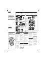
English
This Quick Setup Guide describes how to
connect a DVD player, satellite tuner or set-top
box, TV, speakers and sub woofers so that you
can enjoy multi channel surround sound. Refer
to the operating instructions supplied with the
receiver for details.
The illustrations in the guide designate speakers
as
through
.
Front speaker (left)
Front speaker (right)
Center speaker
Surround speaker (left)
Surround speaker (right)
Surround back speaker
Sub woofer
Sub woofer
1: Installing speakers
The illustration above shows an example of six
speakers and two sub woofers confi guration.
Refer to the operating instructions supplied with
the receiver.
About speaker placement
The front speakers, center speaker and sub
woofers are magnetically shielded to allow it
to be installed near a TV set. However, as the
surround and surround back speakers are not
magnetically shielded, we recommend that you
place them slightly further away from a TV set.
2: Connecting the speakers
The illustrations above show how to connect the
speakers. Before you connect the speakers, check
the speaker label on the rear panel of the speakers
for the speaker type.
About speaker cords
• Black striped wire is minus (–) in polarity and
should be connected to the minus (–) speaker
terminal.
• Use the long speaker cords to connect the
surround and surround back speakers and the
short speaker cords to connect the front and
center speakers.
About speaker jacks
• Connect the
jack to the
jack of the
receiver and connect the
jack to the
jack
of the receiver.
• Refer to the illustration above for details of
connecting speaker cords.
3: Connecting other components
This is an example of how to connect this
receiver and your components. Refer to step 3
of “Getting started” of the operating instructions
supplied with this receiver for details on other
connections and other components.
4: Connect all power cords last
Connect the AC power cord to a wall outlet.
Refer to “Connecting the AC power cord” in the
operating instructions supplied with the receiver.
B
Español
Esta guía de instalación rápida describe cómo
conectar un reproductor de DVD, un sintonizador
vía satélite o un decodifi cador, un televisor, los
altavoces y altavoces potenciadores de graves
para que pueda disfrutar del sonido envolvente
multicanal. Consulte el manual de instrucciones
suministrado con el receptor para obtener más
información.
En las ilustraciones de la guía, los altavoces se
identifi can de
a
.
Altavoz frontal (izquierdo)
Altavoz frontal (derecho)
Altavoz central
Altavoz de sonido envolvente (izquierdo)
Altavoz de sonido envolvente (derecho)
Altavoz posterior de sonido envolvente
Altavoz potenciador de graves
Altavoz potenciador de graves
1: Instalación de los altavoces
La ilustración anterior muestra un ejemplo de
confi guración de un sistema de seis altavoces y
dos altavoces potenciadores de graves. Consulte
el manual de instrucciones suministrado con el
receptor.
Sobre la ubicación del altavoz
Los altavoces frontales, el altavoz central y
los altavoces potenciadores de graves están
protegidos magnéticamente para que puedan
instalarse cerca de un televisor. Sin embargo,
debido a que los altavoces de sonido envolvente
y los altavoces de sonido envolvente posteriores
no están protegidos magnéticamente, se
recomienda situarlos a una distancia considerable
del televisor.
2: Conexión de los altavoces
Las ilustraciones que aparece más arriba
muestra cómo conectar los altavoces. Antes de
conectarlos, compruebe la etiqueta del altavoz
situada en el panel posterior de los mismos para
conocer el tipo de altavoz.
Acerca de los cables de los
altavoces
• El cable con rayas negras tiene una polaridad
negativa (–) y se debe conectar al terminal de
altavoz negativo (–).
• Utilice los cables largos de conexión de
altavoces para conectar los altavoces de
sonido envolvente y los altavoces de sonido
envolvente posteriores, y los cables cortos de
conexión de altavoces para conectar el altavoz
frontal y el central.
Note
To enjoy multi channel
surround sound when
connecting HDMI, be sure
to connect the digital audio
jack as shown and turn off
or mute the TV's volume.
Nota
Para disfrutar del sonido
envolvente multicanal con
conexión HDMI, asegúrese
de conectar la toma de
audio digital como se
muestra en la ilustración,
así como de desactivar o
silenciar el volumen del
televisor.
A
Speaker cord (supplied)/Cables de los
altavoces (suministrada)
B
Monaural audio cord (supplied)/Cable de audio
mono (suministrada)
DVD player/Reproductor de DVD
TV/Televisor
C
HDMI cable (not supplied)/Cable HDMI (no suministrado)
D
Coaxial digital cord (supplied)/Cable digital coaxial (suministrada)
E
Optical digital cord (not supplied)/Cable digital óptico (no suministrado)
F
Audio cord (not supplied)/Cable de audio (no suministrado)
G
Component video cord (not supplied)/Cable de componente
de vídeo (no suministrado)
Acerca de las tomas de los
altavoces
• Conecte la toma
a la toma
del receptor, y
conecte la toma
a la toma
del receptor.
• Consulte la ilustración anterior para obtener
más información sobre cómo conectar los
cables de los altavoces.
3: Conexión de otros
componentes
Este es un ejemplo de cómo conectar este
receptor a los componentes. Consulte el paso
3 de “Procedimientos iniciales” del manual de
instrucciones suministrado con el receptor para
obtener más información sobre cómo realizar
otras conexiones y sobre otros componentes.
4: Conecte todos los cables de
alimentación en último lugar
Conecte el cable de alimentación de ca a una
toma de pared.
Consulte el apartado “Conexión del cable de
alimentación de ca” del manual de instrucciones
suministrado con el receptor.
DDW1600_GBES_2UC A3.indd 1DDW1600_GBES_2UC A3.indd 1 1/9/2007 8:47:18 AM1/9/2007 8:47:18 AM

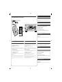
Auto Calibration/Calibración automática
English
Calibrating the speaker settings automatically
You can set up the speakers to obtain the sound you want from all connected speakers automatically by using
the Auto Calibration function. The Auto Calibration function will:
• Check the connection between each speaker and the receiver.
• Adjust the speaker level.
•
Measure the distance of each speaker from your listening position.
1 Connect the supplied optimizer microphone to the AUTO CAL MIC jack on the
receiver.
2 Set up the optimizer microphone.
Place the optimizer microphone at your listening position.You can also use a stool or tripod so that the
optimizer microphone remains at the same height as your ears.
3 Press AMP MENU, then press AUTO CAL.
The Auto Calibration function starts.
For details on the Auto Calibration function, refer to step 6 of "Getting started" of the operating instructions
supplied with this receiver.
Notes
• If there are any obstacles in the path between the optimizer microphone and the speakers, the calibration
cannot be performed correctly. Remove any obstacles from the measurement area to avoid measurement
error.
• The Auto Calibration function cannot detect the sub woofer. Therefore, all sub woofer settings will be
maintained.
123
46
78
0/10
ENTER
9
SYSTEM STANDBY
TV INPUT
SLEEP
AUTO
CAL
TV
?/1
AV
?/1
VIDEO 1 VIDEO 2 VIDEO 3 DVD
2CH A.F.D. MOVIE MUSIC
MEMORY DVD MENU
CLEAR
TOOLSDISPLAY
MUTING
TV VOL
MASTER VOL
FM MODE
D.TUNING
D.SKIP
AMP MENU
SAT TV SA-CD/CD TUNER
?/1
-
F
5
>10/
?/1
AUTO CAL MIC
AUTO CAL
TUNING MODE
TUNING
– +
PHONES
MEMORY/
ENTER
SLEEPDIMMER
MULTI CHANNEL DECODING
SUR BACK
DECODING
2CH A.F.D. MOVIE MUSIC
MODE SPEED
X-ROUND
DISPLAY INPUT MODE
INPUT SELECTOR
MASTER VOLUME
VIDEO 3 IN/PORTABLE AV IN
VIDEO L AUDIO R
AUTO CAL
AMP MENU
?/1
AUTOCAL MIC
AUTOCAL
TUNINGMODE
TUNING
–+
PHONES
MEMORY/
ENTER SLEEPDIMMER
MULTICHANNEL DECODING
SURBACK
DECODING
2CH A.F.D. MOVIE MUSIC
MODE SPEED
X-ROUND
DISPLAY INPUTMODE
INPUTSELECTOR
MASTERVOLUME
VIDEO3 IN/PORTABLEAV IN
VIDEO L AUDIO R
English
Setting up other components
You should set up each component so that the sound is output from the speakers correctly when you playback a
connected component. The following case describes Sony components. Refer to the operating instructions supplied
with each component.
Sony TV
Switch the input of the TV so that an image of the video component you selected is displayed on the TV.
Sony DVD player
1 Select “AUDIO SETUP” on the setup display of the DVD player.
2 Set “AUDIO DRC” to “WIDE RANGE”.
3 Set “DIGITAL OUT” to “ON”.
4 Set “DOLBY DIGITAL” to “DOLBY DIGITAL”.
5 Set “DTS” to “ON” or “DTS”. (Select the setting depending on the model)
Note
Set up the audio format of the playback disc to listen to multi channel sound.
Sony Super Audio CD player
Select a suitable playback area (multi channel or 2 channel). Sound may come out from only the front speaker
left/right when 2 channel is selected.
After the setting
The receiver is now ready to use. Refer to the operating instructions supplied with the receiver for details.
Optimizer microphone (supplied)/
Micrófono optimizador (suministrada)
Español
Confi guración de otros componentes
Es necesario confi gurar cada componente para que el sonido se emita correctamente a través de los altavoces al
reproducir un componente conectado. En el caso siguiente, se describe la confi guración de componentes Sony.
Consulte el manual de instrucciones suministrado con cada componente en cuestión.
Televisor Sony
Cambie la entrada del televisor para que se visualice en el mismo una imagen del componente de vídeo
seleccionado.
Reproductor de DVD Sony
1 Seleccione “AUDIO SETUP” en la pantalla de confi guración del reproductor de DVD.
2 Ajuste “AUDIO DRC” en “WIDE RANGE”.
3 Ajuste “DIGITAL OUT” en “ON”.
4 Ajuste “DOLBY DIGITAL” en “DOLBY DIGITAL”.
5 Ajuste “DTS” en “ON” o bien en “DTS”. (Seleccione el ajuste en función del modelo)
Nota
Confi gure el formato de audio del disco que vaya a reproducir para escuchar sonido multicanal.
Reproductor de Super Audio CD Sony
Seleccione un área de reproducción adecuada (multicanal o bien de 2 canales). Es posible que el sonido se emita
únicamente a través de los altavoces delanteros izquierdo y derecho si se selecciona el ajuste de 2 canales.
Tras realizar el ajuste
El receptor está listo para utilizarse. Consulte el manual de instrucciones suministrado con el receptor para obtener
más información.
Español
Calibración automática de los ajustes del altavoz
Puede instalar los altavoces para obtener automáticamente el sonido que desee a través de todos los altavoces
conectados mediante la función de calibración automática. La función de calibración automática:
• Compruebe las conexiones entre cada altavoz y el receptor.
• Ajuste el nivel del altavoz.
• Calculará la distancia existente entre cada altavoz y la posición de escucha.
1 Conecte el micrófono optimizador suministrado a la toma AUTO CAL MIC del
receptor.
2 Ajuste el micrófono optimizador.
Coloque el micrófono optimizador en su posición de escucha. Puede utilizar también una banqueta o
trípode para que el micrófono optimizador quede a la altura de los oídos.
3 Pulse AMP MENU y, a continuación, AUTO CAL.
Se iniciará la función de calibración automática.
Para obtener más información sobre la función de calibración automática, consulte el paso 6 de
“Procedimientos iniciales” del manual de instrucciones suministrado con el receptor.
Notas
• Si hay obstáculos entre el micrófono optimizador y los altavoces, es posible que la calibración no se lleve a
cabo correctamente. Retire los obstáculos de la zona de medición para evitar errores.
• La función de calibración automática no puede detectar el altavoz potenciador de graves. Por lo tanto, todos
los ajustes del altavoz potenciador de graves se mantendrán.
DDW1600_GBES_2UC A3.indd 2DDW1600_GBES_2UC A3.indd 2 1/9/2007 8:47:21 AM1/9/2007 8:47:21 AM
Transcripción de documentos
3-094-057-22(1) 3: Connecting other components/ 3: Conexión de otros componentes 2: Connecting the speakers/ 2: Conexión de los altavoces Video components/ Componentes de vídeo HT-DDW1600 COMPONENT VIDEO OUTPUT DIGITAL OPTICAL ANTENNA DVD IN VIDEO 2/BD IN SAT IN OUT DIGITAL HDMI OPTICAL ANTENNA DVD IN VIDEO 2/BD IN SAT IN Y AM VIDEO 2/ BD IN OUT HDMI Y PB/CB COAXIAL DVD IN SS-MSP16 L SS-MSP16 R PR/CR VIDEO IN VIDEO IN VIDEO OUT VIDEO IN VIDEO OUT SAT IN L L IN SURROUND BACK VIDEO 1 IN MONITOR OUT L L L R R OUT D-LIGHT SYNC OUT SA-CD/CD/CD-R DVD IN COMPONENT VIDEO MONITOR R R IN AUDIO IN AUDIO IN AUDIO OUT AUDIO IN TV SAT DVD AUDIO OUT VIDEO 1 SUB WOOFER L R R FRONT SURROUND AM VIDEO 2/ BD IN PB/CB SS-SRP16 COAXIAL DVD IN PR/CR VIDEO IN VIDEO OUT VIDEO IN VIDEO OUT VIDEO IN SAT IN L L L R R R DVD IN SURROUND BACK VIDEO 1 IN MONITOR OUT COMPONENT VIDEO MONITOR L R L Y B L OUTPUT OPTICAL CENTER SPEAKERS OUT IN D-LIGHT SYNC OUT SA-CD/CD/CD-R IN AUDIO IN AUDIO IN AUDIO OUT AUDIO IN TV SAT DVD AUDIO OUT VIDEO 1 SUB WOOFER R R FRONT SURROUND CENTER SPEAKERS PB/CB DIGITAL OPTICAL ANTENNA DVD IN VIDEO 2/BD IN SAT IN OUT HDMI PR/CR Y AM VIDEO 2/ BD IN PB/CB E COAXIAL DVD IN PR/CR SURROUND BACK Quick Setup Guide Guía de instalación rápida VIDEO IN VIDEO IN VIDEO OUT VIDEO IN VIDEO OUT SAT IN L L R L R IN AUDIO IN AUDIO IN AUDIO OUT AUDIO IN TV SAT DVD VIDEO 1 SURROUND BACK VIDEO 1 IN MONITOR OUT L L R IN D-LIGHT SYNC OUT SA-CD/CD/CD-R DVD IN COMPONENT VIDEO MONITOR L R OUT L AUDIO OUT SUB WOOFER L R R FRONT SURROUND G CENTER SPEAKERS L R R FRONT SURROUND A Note To enjoy multi channel surround sound when connecting HDMI, be sure to connect the digital audio jack as shown and turn off or mute the TV's volume. A R SPEAKERS SURROUND CENTER DIGITAL OPTICAL ANTENNA DVD IN VIDEO 2/BD IN SAT IN DIGITAL OUT OPTICAL HDMI ANTENNA DVD IN VIDEO 2/BD IN SAT IN Y OUT HDMI AM VIDEO 2/ BD IN Y ANTENNA DVD IN VIDEO 2/BD IN SAT IN OUT HDMI Y AM VIDEO 2/ BD IN PB/CB PB/CB DVD IN COAXIAL PR/CR VIDEO IN VIDEO IN VIDEO OUT VIDEO IN VIDEO OUT SAT IN L DVD IN R R IN AUDIO IN AUDIO IN AUDIO OUT AUDIO IN TV SAT DVD VIDEO 1 AUDIO OUT SUB WOOFER VIDEO IN VIDEO OUT VIDEO IN VIDEO OUT SAT IN MONITOR L L R IN R R FRONT SURROUND SS-CNP16 CENTER SPEAKERS COAXIAL PR/CR VIDEO IN L L L DVD IN SURROUND BACK VIDEO 1 IN MONITOR OUT COMPONENT VIDEO MONITOR L R OUT D-LIGHT SYNC OUT SA-CD/CD/CD-R L IN DVD IN SURROUND BACK VIDEO 1 IN MONITOR OUT COMPONENT VIDEO L L L R R OUT D-LIGHT SYNC OUT SA-CD/CD/CD-R R R IN AUDIO IN AUDIO IN AUDIO OUT AUDIO IN TV SAT DVD VIDEO 1 AUDIO OUT SUB WOOFER L R R FRONT SURROUND CENTER SPEAKERS SA-WP16 + A AUDIO OUT SUB WOOFER A DIGITAL ANTENNA DVD IN VIDEO 2/BD IN SAT IN OUT HDMI Y AM VIDEO 2/ BD IN PB/CB COAXIAL DVD IN PR/CR VIDEO IN VIDEO IN VIDEO OUT VIDEO IN VIDEO OUT SAT IN MONITOR L L IN DVD IN R AUDIO IN AUDIO IN AUDIO OUT AUDIO IN SAT DVD VIDEO 1 SS-SRP16 SURROUND BACK L R IN TV VIDEO 1 IN MONITOR OUT COMPONENT VIDEO L L R R OUT D-LIGHT SYNC OUT SA-CD/CD/CD-R SA-WP16 – CENTER OPTICAL DIGITAL OPTICAL AM VIDEO 2/ BD IN PB/CB COAXIAL AUDIO OUT SUB WOOFER L R R FRONT SURROUND SS-SRP16 CENTER SPEAKERS B B B Speaker cord (supplied)/Cables de los altavoces (suministrada) Monaural audio cord (supplied)/Cable de audio mono (suministrada) Nota Para disfrutar del sonido envolvente multicanal con conexión HDMI, asegúrese de conectar la toma de audio digital como se muestra en la ilustración, así como de desactivar o silenciar el volumen del televisor. DVD IN PR/CR VIDEO IN VIDEO IN VIDEO OUT VIDEO IN VIDEO OUT L L R R OUT D IN D-LIGHT SYNC OUT SA-CD/CD/CD-R C L R R IN AUDIO IN AUDIO IN AUDIO OUT AUDIO IN SAT DVD VIDEO 1 AUDIO OUT SUB WOOFER C G Y L INPUT PB/CB R AUDIO R R FRONT SURROUND SPEAKERS C D E A English This Quick Setup Guide describes how to connect a DVD player, satellite tuner or set-top box, TV, speakers and sub woofers so that you can enjoy multi channel surround sound. Refer to the operating instructions supplied with the receiver for details. The illustrations in the guide designate speakers as through . Front speaker (left) Front speaker (right) Center speaker Surround speaker (left) Surround speaker (right) Surround back speaker Sub woofer Sub woofer 1: Installing speakers The illustration above shows an example of six speakers and two sub woofers configuration. Refer to the operating instructions supplied with the receiver. About speaker placement The front speakers, center speaker and sub woofers are magnetically shielded to allow it to be installed near a TV set. However, as the surround and surround back speakers are not magnetically shielded, we recommend that you place them slightly further away from a TV set. DDW1600_GBES_2UC A3.indd 1 DVD player/Reproductor de DVD 10 mm L 2: Connecting the speakers The illustrations above show how to connect the speakers. Before you connect the speakers, check the speaker label on the rear panel of the speakers for the speaker type. About speaker cords • Black striped wire is minus (–) in polarity and should be connected to the minus (–) speaker terminal. • Use the long speaker cords to connect the surround and surround back speakers and the short speaker cords to connect the front and center speakers. About speaker jacks • Connect the jack to the jack of the receiver and connect the jack to the jack of the receiver. • Refer to the illustration above for details of connecting speaker cords. 3: Connecting other components This is an example of how to connect this receiver and your components. Refer to step 3 of “Getting started” of the operating instructions supplied with this receiver for details on other connections and other components. VIDEO 1 IN MONITOR OUT L TV F DVD IN COMPONENT VIDEO COMPONENT VIDEO INPUT Sony Corporation © 2007 Printed in Malaysia L SAT IN MONITOR OUTPUT 1: Installing speakers/ 1: Instalación de los altavoces Satellite tuner or Set-top box/Sintonizador vía satélite o decodificador HDMI cable (not supplied)/Cable HDMI (no suministrado) Coaxial digital cord (supplied)/Cable digital coaxial (suministrada) Optical digital cord (not supplied)/Cable digital óptico (no suministrado) Español Esta guía de instalación rápida describe cómo conectar un reproductor de DVD, un sintonizador vía satélite o un decodificador, un televisor, los altavoces y altavoces potenciadores de graves para que pueda disfrutar del sonido envolvente multicanal. Consulte el manual de instrucciones suministrado con el receptor para obtener más información. En las ilustraciones de la guía, los altavoces se identifican de a . Altavoz frontal (izquierdo) Altavoz frontal (derecho) Altavoz central Altavoz de sonido envolvente (izquierdo) Altavoz de sonido envolvente (derecho) Altavoz posterior de sonido envolvente Altavoz potenciador de graves Altavoz potenciador de graves 1: Instalación de los altavoces La ilustración anterior muestra un ejemplo de configuración de un sistema de seis altavoces y dos altavoces potenciadores de graves. Consulte el manual de instrucciones suministrado con el receptor. PR/CR TV/Televisor F G Audio cord (not supplied)/Cable de audio (no suministrado) Component video cord (not supplied)/Cable de componente de vídeo (no suministrado) Sobre la ubicación del altavoz Los altavoces frontales, el altavoz central y los altavoces potenciadores de graves están protegidos magnéticamente para que puedan instalarse cerca de un televisor. Sin embargo, debido a que los altavoces de sonido envolvente y los altavoces de sonido envolvente posteriores no están protegidos magnéticamente, se recomienda situarlos a una distancia considerable del televisor. 2: Conexión de los altavoces Las ilustraciones que aparece más arriba muestra cómo conectar los altavoces. Antes de conectarlos, compruebe la etiqueta del altavoz situada en el panel posterior de los mismos para conocer el tipo de altavoz. Acerca de los cables de los altavoces • El cable con rayas negras tiene una polaridad negativa (–) y se debe conectar al terminal de altavoz negativo (–). • Utilice los cables largos de conexión de altavoces para conectar los altavoces de sonido envolvente y los altavoces de sonido envolvente posteriores, y los cables cortos de conexión de altavoces para conectar el altavoz frontal y el central. Acerca de las tomas de los altavoces • Conecte la toma a la toma del receptor, y conecte la toma a la toma del receptor. • Consulte la ilustración anterior para obtener más información sobre cómo conectar los cables de los altavoces. 3: Conexión de otros componentes Este es un ejemplo de cómo conectar este receptor a los componentes. Consulte el paso 3 de “Procedimientos iniciales” del manual de instrucciones suministrado con el receptor para obtener más información sobre cómo realizar otras conexiones y sobre otros componentes. 4: Conecte todos los cables de alimentación en último lugar Conecte el cable de alimentación de ca a una toma de pared. Consulte el apartado “Conexión del cable de alimentación de ca” del manual de instrucciones suministrado con el receptor. 4: Connect all power cords last Connect the AC power cord to a wall outlet. Refer to “Connecting the AC power cord” in the operating instructions supplied with the receiver. 1/9/2007 8:47:18 AM English Auto Calibration/Calibración automática ?/1 MASTER VOLUME MULTI CHANNEL DECODING DISPLAY TUNING MODE INPUT MODE INPUT SELECTOR – TUNING + AUTO CAL AUTO CAL MIC MEMORY/ ENTER DIMMER SLEEP SUR BACK DECODING Setting up other components You should set up each component so that the sound is output from the speakers correctly when you playback a connected component. The following case describes Sony components. Refer to the operating instructions supplied with each component. Optimizer microphone (supplied)/ Micrófono optimizador (suministrada) X-ROUND 2CH A.F.D. MOVIE MUSIC MODE SPEED VIDEO 3 IN/PORTABLE AV IN PHONES VIDEO L AUDIO R Sony TV Switch the input of the TV so that an image of the video component you selected is displayed on the TV. Sony DVD player ?/1 MASTER VOLUME MULTI CHANNEL DECODING DISPLAY TUNING MODE TV INPUT SLEEP AUTO CAL TV ?/1 AV ?/1 ?/1 AUTO CAL SYSTEM STANDBY VIDEO 1 VIDEO 2 VIDEO 3 AUTO CAL DVD AUTO CAL MIC MEMORY/ ENTER SAT TV 2CH A.F.D. SA-CD/CD TUNER MOVIE 3 FM MODE 4 5 6 7 8 9 >10/ - 0/10 SLEEP SUR BACK DECODING X-ROUND 2CH A.F.D. MOVIE MUSIC MODE SPEED MUSIC AMP MENU 2 DIMMER VIDEO 3 IN/PORTABLE AV IN PHONES VIDEO 1 INPUT MODE INPUT SELECTOR – TUNING + L AUDIO R AMP MENU Set “AUDIO DRC” to “WIDE RANGE”. Set “DIGITAL OUT” to “ON”. Set “DOLBY DIGITAL” to “DOLBY DIGITAL”. Set “DTS” to “ON” or “DTS”. (Select the setting depending on the model) D.SKIP MEMORY DVD MENU ENTER Sony Super Audio CD player TOOLS MUTING F Select “AUDIO SETUP” on the setup display of the DVD player. Note Set up the audio format of the playback disc to listen to multi channel sound. D.TUNING CLEAR DISPLAY 1 2 3 4 5 Select a suitable playback area (multi channel or 2 channel). Sound may come out from only the front speaker left/right when 2 channel is selected. TV VOL MASTER VOL After the setting The receiver is now ready to use. Refer to the operating instructions supplied with the receiver for details. English Español Calibrating the speaker settings automatically Calibración automática de los ajustes del altavoz You can set up the speakers to obtain the sound you want from all connected speakers automatically by using the Auto Calibration function. The Auto Calibration function will: • Check the connection between each speaker and the receiver. • Adjust the speaker level. • Measure the distance of each speaker from your listening position. Puede instalar los altavoces para obtener automáticamente el sonido que desee a través de todos los altavoces conectados mediante la función de calibración automática. La función de calibración automática: • Compruebe las conexiones entre cada altavoz y el receptor. • Ajuste el nivel del altavoz. • Calculará la distancia existente entre cada altavoz y la posición de escucha. 1 Connect the supplied optimizer microphone to the AUTO CAL MIC jack on the receiver. 1 Conecte el micrófono optimizador suministrado a la toma AUTO CAL MIC del receptor. 2 Set up the optimizer microphone. 2 Ajuste el micrófono optimizador. Coloque el micrófono optimizador en su posición de escucha. Puede utilizar también una banqueta o trípode para que el micrófono optimizador quede a la altura de los oídos. Place the optimizer microphone at your listening position.You can also use a stool or tripod so that the optimizer microphone remains at the same height as your ears. 3 Press AMP MENU, then press AUTO CAL. The Auto Calibration function starts. 3 Pulse AMP MENU y, a continuación, AUTO CAL. Se iniciará la función de calibración automática. For details on the Auto Calibration function, refer to step 6 of "Getting started" of the operating instructions supplied with this receiver. Para obtener más información sobre la función de calibración automática, consulte el paso 6 de “Procedimientos iniciales” del manual de instrucciones suministrado con el receptor. Notes • If there are any obstacles in the path between the optimizer microphone and the speakers, the calibration cannot be performed correctly. Remove any obstacles from the measurement area to avoid measurement error. • The Auto Calibration function cannot detect the sub woofer. Therefore, all sub woofer settings will be maintained. Notas • Si hay obstáculos entre el micrófono optimizador y los altavoces, es posible que la calibración no se lleve a cabo correctamente. Retire los obstáculos de la zona de medición para evitar errores. • La función de calibración automática no puede detectar el altavoz potenciador de graves. Por lo tanto, todos los ajustes del altavoz potenciador de graves se mantendrán. Español Configuración de otros componentes Es necesario configurar cada componente para que el sonido se emita correctamente a través de los altavoces al reproducir un componente conectado. En el caso siguiente, se describe la configuración de componentes Sony. Consulte el manual de instrucciones suministrado con cada componente en cuestión. Televisor Sony Cambie la entrada del televisor para que se visualice en el mismo una imagen del componente de vídeo seleccionado. Reproductor de DVD Sony 1 2 3 4 5 Seleccione “AUDIO SETUP” en la pantalla de configuración del reproductor de DVD. Ajuste “AUDIO DRC” en “WIDE RANGE”. Ajuste “DIGITAL OUT” en “ON”. Ajuste “DOLBY DIGITAL” en “DOLBY DIGITAL”. Ajuste “DTS” en “ON” o bien en “DTS”. (Seleccione el ajuste en función del modelo) Nota Configure el formato de audio del disco que vaya a reproducir para escuchar sonido multicanal. Reproductor de Super Audio CD Sony Seleccione un área de reproducción adecuada (multicanal o bien de 2 canales). Es posible que el sonido se emita únicamente a través de los altavoces delanteros izquierdo y derecho si se selecciona el ajuste de 2 canales. Tras realizar el ajuste El receptor está listo para utilizarse. Consulte el manual de instrucciones suministrado con el receptor para obtener más información. DDW1600_GBES_2UC A3.indd 2 1/9/2007 8:47:21 AM-
 1
1
-
 2
2


Sony 3-094-057-22(1) Manual de usuario
- Categoría
- Receptores AV
- Tipo
- Manual de usuario
en otros idiomas
- English: Sony 3-094-057-22(1) User manual
Artículos relacionados
-
Sony HT-DDW795 Guía de instalación
-
Sony STR-DG710 Guía de instalación
-
-
-
Sony STR-DG720 Guía de instalación
-
Sony HT-DDW890 Guía de instalación
-
Sony HT-DDW990 El manual del propietario
-
Sony STR-DG510 Manual de usuario
-
-