
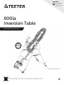
800ia
Inversion Table
To download and print Teeter’s 800ia instructions, visit the product support page at teeter.com.
Para descargar e imprimir las instrucciones de montaje de 800ia en español, visite teeter.com
* Specifications may vary from this image and
are subject to change without notice.
Assembly Instructions
YEAR
5
W
A
R
R
A
N
T
Y
FULL
EN
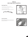
NEW!
Follow along with
your smartphone
to make assembly
even easier!

Owner’s Manual (attached to the equipment)
Important Safety Instructions ........................1
User Settings ........................................ 2
Prepare to Invert..................................3 – 4
Inverting ..........................................4 – 5
Storage & Maintenance .............................. 5
Get the Most out of Your Teeter .....................6
Assembly Instructions
Important Safety Instructions ........................1
Items for Assembly .................................. 2
Understanding Your Inversion Table ..................3
Safety Warning Labels & Product Specifications ..... 4
Before Beginning Assembly ......................... 5
Assembly Steps...................................6 – 11
Misassembly Check..................................12
Before Inverting .....................................13
Warranty Terms & Registration.......................15
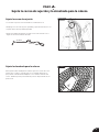
Congratulations on your purchase of a Teeter 800ia Inversion Table! This product has been carefully engineered to provide you with
precision rotation control and security to ensure the most comfortable and effective inversion experience.
In order to utilize this product to its fullest extent, it is critical that you follow the assembly instructions, read and fully understand the
Owner’s Manual attached to the equipment, and review the Getting Started DVD prior to using your new Teeter Inversion Table.
For step-by-step, 3D interactive instructions, download BILT (a FREE mobile app) to your smartphone to follow along.
See Page 5 for instructions on how to download BILT.
To register your product warranty, go to teeter.com/Support/Warranty-Registration
If you have any questions concerning assembly or if any parts are missing, DO NOT RETURN THE ITEM TO THE STORE
OR CONTACT THE RETAILER. Our dedicated customer service experts can help! Contact Teeter Customer Service
at 800.847.0143, or via online forms or Live Chat at teeter.com.

WARNING
!
IMPORTANT SAFETY INSTRUCTIONS
READ ALL INSTRUCTIONS BEFORE USING THE INVERSION TABLE
SAVE THESE INSTRUCTIONS
BEFORE YOU BEGIN: Review all steps before beginning assembly and read all precautions before using the inversion table.
Carefully adhere to the Assembly Instructions and Owner’s Manual to help ensure safety and product integrity.
1
FAILURE TO FOLLOW INSTRUCTIONS AND WARNINGS COULD RESULT IN SERIOUS INJURY OR DEATH.
To reduce the risk of injury:
• Read and understand all the instructions, review all other accompanying documents, and inspect the equipment before using the
inversion table. It is your responsibility to familiarize yourself with the proper use of this equipment and the inherent risks of inversion
if these instructions are not followed, such as falling on your head or neck, pinching, entrapment, equipment failure, or aggravating a
pre-existing medical condition. It is the responsibility of the owner to ensure that all users of the product are fully informed about the
proper use of the equipment and all safety precautions.
• DO NOT use the equipment without a licensed physician’s approval. Carefully review the following list of medical contraindications for
inversion with your licensed physician (this is not an exhaustive list, it is intended only for reference):
• ALWAYS be certain the Ankle Lock System is properly adjusted and fully engaged, and that your ankles are secure before using
the equipment. HEAR, FEEL, SEE and TEST that the Ankle Lock System is snug, close-fitting and secure EVERY TIME you use
the equipment.
• ALWAYS wear securely tied lace-up shoes with a flat sole, such as a normal tennis-style shoe.
• DO NOT wear any footwear that could interfere with securing the Ankle Lock System, such as shoes with thick soles, boots, high-tops
or any shoe that extends above the anklebone.
• DO NOT use the inversion table until it is adjusted properly for your height and body weight. Improper settings can cause rapid
inversion or make returning upright difficult. New users, and users who are physically or mentally compromised, will require the
assistance of a spotter. Make sure the equipment is set to your unique user settings prior to each use.
• DO NOT sit up or raise head to return upright. Instead, bend knees and slide your body to the foot-end of the inversion table to change
weight distribution. If locked out in full inversion, follow the instructions for releasing from the locked position before returning upright.
• DO NOT continue using the equipment if you feel pain or become light-headed or dizzy while inverting. Immediately return to the
upright position for recovery and eventual dismount.
• DO NOT use if you are over 6 ft 6 in (198 cm) or over 300 lbs. (136 kg). Structural failure could occur or head/neck may impact the floor
during inversion.
• DO NOT allow children to use this machine. Keep children, bystanders, and pets away from machine while in use. The inversion table
is not intended for use by persons with reduced physical, sensory or mental capabilities, unless they are given supervision and
instruction concerning use of the machine by a person responsible for their safety.
• DO NOT store the inversion table upright if children are present. Fold and lay the table on the floor. DO NOT store outdoors.
• DO NOT use aggressive movements, or use weights, elastic bands, any other exercise or stretching device or non-Teeter® attachments
while on the inversion table. Use the inversion table only for its intended use as described in this manual.
• DO NOT drop or insert any object into any opening. Keep body parts, hair, loose clothing and jewelry clear of all moving parts.
• DO NOT use in any commercial, rental or institutional setting. This product is intended for indoor, home-use only.
• DO NOT operate equipment while under the influence of drugs, alcohol, or medication that may cause drowsiness or disorientation.
• ALWAYS inspect the equipment prior to use. Make sure all fasteners are secure.
• ALWAYS replace defective components immediately and/or keep the equipment out of use until repair.
• ALWAYS position equipment on a level surface and away from water or ledges that could lead to accidental immersion or falls.
• Refer to additional warning notices posted on the equipment. If a product label or Owner’s Manual should become lost, damaged or
illegible, contact Customer Service for replacement.
• Middle ear infection
• Extreme obesity
• Pregnancy
• Hiatal or ventral hernia
• Eye conditions like glaucoma,
retinal detachment or
conjunctivitis
• Chronic sinusitis
• High blood pressure or
hypertension
• Heart or circulatory disorders
• Use of anticoagulants
(including high doses of
aspirin)
• Weakness, frailty, or mobility
issues
• Dizziness, trouble with
coordination or head-down
disorientation
• Vertigo, motion sickness or
inner ear disorders
• Brain injury or recent head
trauma
• Recent stroke or transient
ischemic attack
• Spinal injury or conditions
impacting the spinal cord
• Cerebral sclerosis
• Medical conditions associated
with the weight-bearing joints
• Acutely swollen joints
• Bone weakness (osteoporosis)
• Recent or unhealed fractures
• Medullary pins or surgically
implanted orthopedic supports
• Any other medical condition
that may be made more
severe by an elevation of blood
pressure, intracranial pressure
or the mechanical stress of the
inverted position

REV.
DESCRIPTION
REV.DATE
APP.DATE
APPROVED
說明書-0513 2015/5/11
D
細部放大圖 D
比例 1 : 7
C
A
B
D
E
6
5
4
3
29
8
7
C
A
B
D
E
F
G
H
1
23456789
F
G
H
2
Items for Assembly
Items not shown to scale. Hardware drawings located on the insert inside each Hardware Kit.
A-Frame Base Assembly
with pre-assembled Angle Tether
NX2200
F51007
Table Bed Assembly
Use with Table Bed Assembly
Hardware Kit (HK1010)
FS2045
F51064
IA8105
ITEM NO. ITEM NAME
A-Frame Base Assembly
NX2200 A-Frame
F51007 Angle Tether pre-assembled to A-Frame
Handle Assembly
FS2045 Traction Support™ Handles (2)
FS2025 Hinge Covers (2)
HK1009 Handle Assembly Hardware Kit
HK1002 Hinge Cover Assembly Hardware Kit
Roller Hinge Assembly
F51064 3-Hole Roller Hinges (2)
Table Bed Assembly
EP2300 Table Bed
HK1010 Table Bed Assembly Hardware Kit
Handle Assembly
Use with Handle Assembly
Hardware Kit (HK1009) and Hinge Cover
Assembly Hardware Kit (HK1002)
Roller Hinge Assembly
Optional Accessories
IA1149
5mm Allen Wrench
Main Shaft Assembly
with EZ-Reach™ Ankle Lock System
F51088
ITEM NO. ITEM NAME
Main Shaft Assembly
NX1690 with EZ-Reach™ Ankle Lock System
Optional Accessories
IA8105 Head Pillow
Tools Provided for Assembly
IA1149 5mm Allen Wrench (1)
EP1128A 6mm Allen Wrench (1)
F51088 Open-Ended Wrenches (2)
Product Support
LI8003 Getting Started DVD
LI8000 Owner’s Manual pre-assembled to A-Frame
FS2025
EP2300
Open-Ended
Wrenches
Tools Provided for Assembly
NX1690
EP1128A
6mm Allen Wrench
H2小枕頭
MATERIAL: 黑色PVC皮料/白色泡棉
彩色印刷LOGO
車縫位置
魔鬼氈(勾面)
在黏扣帶上方
黏扣帶
魔鬼氈(勾面)
在上方
黑色PVC皮料 0.7 m/m
白色泡棉 25D
車縫魔鬼氈勾面
Getting Started DVD
LI8003
Product Support
LI8000
Owner’s Manual

3
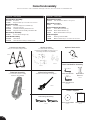
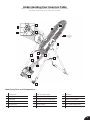
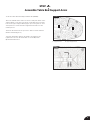
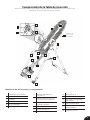
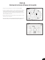
Identifying Parts and Components
Understanding Your Inversion Table
Before reading further, study the drawing below to familiarize yourself with the
important components of your Teeter Inversion Table.
1 Head Pillow
2 Support Arms
3 Table Bed
4 Pivot Pins
5 Hinge Plates
6 Self-Locking Hooks
7 3-Hole Roller Hinges
8 Traction Support™ Handles
9 Height-Selector Locking Pin
10 Spreader Arms
11 Angle Tether
12 Crossbar
Located on
back of table
bed.
1
2
3
9
10
8
13
11
15
16
17
4
5
6
7
14
12
13 A-Frame
14 Main Shaft
15 Ankle Lock System
16 Ankle Comfort Dial™
17 Non-Skid Stability Feet
18 De-rattler Knob
18

4
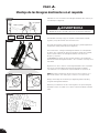
Safety Warning Labels & Product Specifications
Important: Please review all labels and supporting materials before using your inversion table.
This drawing indicates the locations of the warning labels found on your product. If a label is missing, illegible or is removed,
contact Teeter Customer Service to request a complimentary replacement label.
Note: Image and labels below not shown at actual size.
Assembled Non-Use Dimensions: 60.0 in (L) x 28.8 in (W) x 59.3 in (H) (152.4 x 73.2 x 150.5 cm)
Maximum In-Use Dimensions: 82.0 in (L) x 28.8 in (W) x 86 in (H) (208.3 x 73.2 x 218.4 cm)
Storage Dimensions: 20.0 in (L) x 28.8 in (W) x 66 in (H) (50.8 x 73.2 x 167.6 cm)
Weight (approx.): 71 lbs. (32.2 kg)
28.8 in (73.2 cm)
59.3 in (150.5 cm)
60.0 in (152.4 cm)
The 800ia is shown here.
Your actual model may vary.

Unpack and Prepare Your Workspace
• If possible, set up the product at or near the space in which you intend to use it to avoid moving it later.
• Unpack all parts and support materials. Follow the unpacking instructions included in the box. Set aside packing materials
and clear your work area.
• Locate the Hardware Kits, packaged with the manuals. They are labeled to correspond with the assembly process.
• The Getting Started DVD provides step-by-step instruction on how to assemble your product. You may find it helpful to follow along
with the DVD by watching it on either your TV or computer. The DVD is divided into the following sections:
• Assembly - Follow step-by-step instruction on how to assemble your inversion table.
• User Settings - Personalize your inversion experience by adjusting four customizable settings.
• Use Instructions - Learn how to test your balance and rotation control, and how to properly invert and return upright.
• Advanced Stretching & Exercises - Use your Teeter for rotational stretches, sit ups, squats and more!
• BONUS Healthy Back Routines*
Dr. Shawn leads you through 5 original Healthy Back Routines, including one designed specifically for
use with your inversion table! *Not available in French or Spanish.
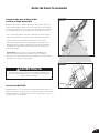
Before Beginning Assembly
5
For step-by-step, 3D interactive instructions, download BILT (a FREE mobile app) to your
smartphone to follow along. Simply download the BILT app by scanning the QR code
below and then search for Teeter 800ia within the BILT app to get started!
Making Assembly Even Easier with

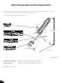
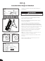
STEP 1
Assemble A-Frame Base & Traction Support Handles
• On a level surface, position the A-Frame so that it is standing upright
and the Stability Feet are on the ground.
• Gently push down on the Spreader Arms to ensure they are fully open
and in the “locked” position (Figure 1).
• Look for temporary circular assembly assistance labels on the
A-Frame. RIGHT, LEFT, FRONT, and REAR indicate your position while
using the equipment, not facing it. These labels can be removed easily
upon completion of assembly.
Assemble Traction Support Handles
• Locate the Handle Assembly Hardware Kit (HK1009).
• Insert the Left and Right handles into the A-Frame (Figure 2a).
• Insert the Hex Bolts from inside of the A-Frame and fasten with
the Nuts from the outside of the A-Frame (Figure 2b).
• Tighten with the wrenches provided.
Assemble Hinge Covers to Hinge Plates
• Locate the Hinge Cover Assembly Hardware Kit (HK1002).
• Select the corresponding Hinge Covers for the left and right sides of
the A-Frame by aligning each with the shape of the Hinge Plate
(Figure 3).
• Secure with (2) Allen Head Bolts for each side using a 5mm
Allen Wrench provided. Be careful not to overtighten.
6
REV.
DESCRIPTION
REV.DATE
APP.DATE
APPROVED
說明書-0513 2015/5/11
D
細部放大圖 D
比例 1 : 7
C
A
B
D
E
6
5
4
3
29
8
7
C
A
B
D
E
F
G
H
1
23456789
F
G
H
1 - Spreader Arms 2 - Crossbar
LEFT
RIGHT
FIGURE 1
1
2
REAR
FRONT
FIGURE 3
LOCKED
FIGURE 1a
UNLOCKED
FIGURE 2a FIGURE 2b

7
STEP 2
• Locate the Table Bed Assembly Hardware Kit (HK1010).
• Place the Table Bed face down on the floor and push down on the
Support Beam, so the two holes align evenly with the holes at the
base of the Upper Support Arms (Figure 4). You may have to exert
extra pressure to ensure that the Support Beam slides over the
rubber spacers.
• Insert the two Bolts into the open holes. Fasten each bolt with a
Washer and Nut (Figure 5).
• Using the 6mm Allen Wrench provided to steady the bolts,
tighten the nuts onto the bolts with one of the 10/13 mm
Open Ended Wrenches.
Assemble Table Bed Support Arms
FIGURE 4
FIGURE 5
1
2
1 - Support Beam 2 - Upper Support Arms

8
STEP 3
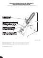
Assemble Roller Hinges to Table Bed
UNLOCKED
Bracket Pin Cam Lock
Pivot Pin Bracket
C
B
A
UNLOCK LOCK
LOCKED
FIGURE 6
FIGURE 8
FIGURE 7
FIGURE 9
FIGURE 10
NEVER disassemble the Roller Hinge Pivot Pin.
WARNING
!
• For ease of assembly, rest the Table Bed against the Crossbar
(Figure 7) at the front of the A-Frame.
• On one side of the Table Bed, lift and hold the Cam Lock up all
the way to unlock (Figure 8).
• In your other hand, hold one Roller Hinge near the Pivot Pin.
With the Pivot Pin facing out (away from the Table Bed), slide the
bottom of the Roller Hinge between the Cam Lock and the Bracket.
TIP: Make sure that the Cam Lock is completely open when inserting
the Roller Hinge, otherwise assembly will be more difficult.
• Engage one of the holes in the Roller Hinge over the Bracket Pin.
Figure 10 shows the Roller Hinge installed correctly, with the
Bracket Pin engaged in Setting C.
NOTE: Refer to the Owner’s Manual for an explanation of the hole
settings. If you are unsure, use Setting C to start.
• Push down on the Cam Lock (Figure 9) to lock it and secure the
Roller Hinge.
• Repeat on other side. Make sure the Roller Hinges are in the
same hole setting on both sides.
• Familiarize yourself with the 3-Hole Roller Hinge and Cam Lock
terms (Figure 6).

9
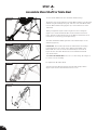
STEP 4
Assemble Table Bed to A-Frame
• Face the front of the A-Frame where the Crossbar is located (Figure 9).
• Grasp both Roller Hinges, right above the Cam Lock, and lift the
Table Bed. Allow the top of the Table Bed to rotate toward the floor,
so that the back of the Table Bed is now facing you and the top of the
Table Bed is in front of the Crossbar (Figure 10).
• Lower each Roller Hinge Pivot Pin into the A-Frame hinge plates, one
side at a time (Figure 11). The Self-Locking Hooks will open to allow the
Pivot Pin into the Hinge Plate slot, then automatically snap closed
over the Pivot Pin.
TIP: You may need to push outward on the Hinge Plate in order for
the second Pivot Pin to lock in place.
• Make sure that each Pivot Pin is seated at the base of the slot in the
Hinge Plates, and that the Self-Locking Hooks have closed over both
Pivot Pins (Figures 11a & 11b).
Failure of the Self-Locking Hooks to close over both Roller Hinge
Pivot Pins is an indication of improper assembly and if not corrected
could result in serious injury or death!
WARNING
!
• Rotate the Table Bed into the use position (Figure 12). Ensure that
it rotates smoothly. See also Image A on Page 12 to ensure
correct assembly.
TOP VIEW
INSIDE VIEW
FRONT
REAR
FIGURE 11
FIGURE 12
FIGURE 11b
FIGURE 11a
FIGURE 9
FIGURE 10

10
STEP 5
Assemble Main Shaft to Table Bed
• Loosen the De-Rattler Knob on the Main Shaft Housing.
• Facing the front of the A-Frame, hold the Main Shaft in your left hand
with the height markings facing up. Slide the end of the Main Shaft
into the Main Shaft Housing (Figure 13), located at the base of the
Table Bed.
• With your right hand, pull out the Height-Selector Locking Pin
(Figure 14) to allow the Main Shaft to slide in further and release
in the desired height setting. Refer to the Owner’s Manual for more
information on selecting your height setting.
• The Main Shaft MUST REST against the Crossbar bumper on the
A-Frame (Figure 15).
IMPORTANT: The Crossbar prevents the Table Bed from rotating
forward when the user steps on the Ankle Comfort Dial. If the
Main Shaft does not rest on the Crossbar bumper as shown in
Figure 15, then the Table Bed has been assembled backwards
onto the A-Frame.
This MUST BE CORRECTED before use. See also Image B on Page 12
to ensure correct assembly.
• Re-tighten the De-rattler Knob.
• Test the inversion table by hand for smooth and steady rotation
(Figure 16) and ensure that all fasteners are secure.
REV.
DESCRIPTION
REV.DATE
APP.DATE
APPROVED
說明書-0513 2015/5/11
C
A
B
D
E
6
5
4
3
29
8
7
C
A
B
D
E
F
G
H
1
23456789
F
G
H
FIGURE 13
FIGURE 14
FIGURE 15
FIGURE 16

11
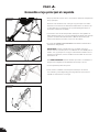
STEP 6
Attach Angle Tether & Head Pillow
FIGURE 20
FIGURE 21
Attach Angle Tether
• The tether will come pre-assembled to the A-Frame.
• Unfold the adjustable tether and clip it to the U-Bar on the
underside of the Table Bed (Figure 20).
• Slide the buckle to lengthen or shorten the strap depending on
your desired maximum angle of inversion.
Attach Head Pillow
Attach the Head Pillow by securing the Velcro Straps through the
holes in the Table Bed (Figure 21). You may customize the position
depending on your preference.
LENGTHEN
SHORTEN

12
說明書-0513 2015/5/11
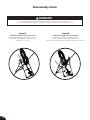
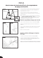
Image B
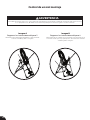
Go back to Step 4 for instruction.
Demonstrates that the Table Bed has been
assembled into the A-Frame backwards so the
Main Shaft is not resting on the Crossbar and must be corrected.
Image A
Go back to Step 3 for instruction.
Demonstrates that the Roller Hinges have been
assembled upside down into the Table Bed
and must be corrected.
Misassembly Check
If your Teeter Inversion Table looks like either of these images, your inversion table has
been misassembled and is unfit for use. Improper assembly could result in serious injury or death!
WARNING
!
REV.
DESCRIPTION
REV.DATE
APP.DATE
APPROVED
說明書-0513 2015/5/11
D
細部放大圖 D
比例 1 : 7
C
A
B
D
E
6
5
4
3
29
8
7
C
A
B
D
E
F
G
H
1
23456789
F
G
H

13
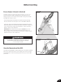
Before Inverting
FIGURE 24a
FIGURE 24
Ensure Owner’s Manual is Attached
The Owner’s Manual contains important information on how to use
your Teeter Inversion Table, including how to personalize the user
settings, properly secure and release the Ankle Lock System, and test
and adjust the rotation control.
• If not already attached, thread the provided metal chain through
the pre-punched hole in the upper corner of the Owner’s Manual.
• Secure the chain to the A-Frame through the designated hole in the
Hinge Plate (Figure 24 & 24a). Allow the Owner’s Manual to hang freely
on the outside of the A-Frame Spreader Arms so it doesn’t interfere
with the rotation of the Table Bed.
IMPORTANT: Once attached to the A-Frame, DO NOT remove the
Owner’s Manual. It should remain permanently attached to your
inversion table to serve as a reference for all users in regards to proper
adjustment and use of the equipment.
WARNING
!
View the Remainder of the DVD
The Getting Started DVD is a helpful supplement to the Owner’s Manual,
with easy-to-follow instructions on user settings, how to invert, storage
and maintenance, and even stretching and exercises you can do with
your Teeter.
Read the Owner’s Manual thoroughly before using your
Teeter Inversion Table. Improper settings could result
in serious injury or death!


HOW TO SUBMIT YOUR REGISTRATION:
Step 1
Fill out this information for your own records.
Step 2
Go online to teeter.com to register your warranty.
Handling and transportation costs related to product warranty service only are covered by this warranty. This warranty does
not cover damage resulting from improper handling, assembly, or installation, repairs made by others, accident, misuse,
or abuse. Under no circumstances shall Teeter, or any other party involved in the sale of this product, have any liability for
incidental or consequential damage arising from breach of an express or implied warranty on any Teeter product.
EXCEPT AS SET FORTH ABOVE, NO WARRANTY IS GIVEN WITH RESPECT TO ANY TEETER PRODUCT, AND ALL EXPRESS
WARRANTIES ARE DISCLAIMED. This warranty shall be governed by the laws of the State of Washington, USA. To
the extent this warranty is found not to be enforceable, it shall be deemed revised to the extent necessary to make it
enforceable. This warranty and any controversy or claim arising out of this warranty or its interpretation shall be governed
by the laws of the State of Washington, USA. Any controversy or claim arising out of or relating to this warranty, its
interpretation, or any alleged breach thereof, which cannot be amicably settled between Teeter and the owner within
sixty (60) days of written notice by the aggrieved party to the other, shall be finally settled by arbitration submitted to
three (3) arbitrators selected from the panels of the arbitrators of the American Arbitration Association located closest to
Teeter’s principal place of business.
Some states do not allow the exclusion of incidental or consequential damage from a warranty, so the above limitation or
exclusion may not apply to you. Some states do not allow limitations on how long an implied warranty lasts, so the above
limitation may not apply to you. This warranty gives you specific legal rights, and you may also have other rights which may
vary from state to state.
PLEASE RETAIN THIS FOR YOUR RECORDS
Date of Purchase
Product & Model
Dealer Name
Serial No.
YEAR
5
W
A
R
R
A
N
T
Y
FULL
During the period starting with the day of retail purchase and continuing for five (5) years, Teeter
extends to the owner a repair and replacement warranty against manufacturing defects in
materials, workmanship, fabrics and padding. Teeter will repair or replace any such defect and will
pay the costs of all parts, labor and transportation. If a repair or replacement is not commercially
practical or cannot timely be made, then Teeter will, at the original Purchaser’s option, replace
with a comparable product or refund the purchase price.
FULL 5 YEAR WARRANTY
If you are unable to go online, you can request a warranty card to be mailed to you by calling Customer Service at 800-847-0143.
Please DO NOT mail this to Teeter.
15
The Teeter warranty set forth below and on Teeter’s website applies to US and Canadian customers only.
For international customers, please consult your local distributor for warranty information which will vary
depending on country.

U.S. and Foreign Patents Apply. Teeter and Teeter logo are registered trademarks of Teeter. Specifications subject to change without notice.
© COPYRIGHT 2015 Teeter. International Law Prohibits Any Copying. LI8001 0415-0
If you have any trouble assembling the equipment, or questions
about its use, please contact customer service.
Medical Device Safety Service
GmbH
Schiffgraben 41
30175 Hannover
Germany
Tel. +49 511 62628630
EC REP
International: Teeter International, Ltd.
Gor-Ray House
758 Great Cambridge Rd
Enfield
Middlesex EN1 3GN
United Kingdom
teeterintl.com | inf[email protected]
USA: Teeter
9902 162nd St. Ct. E.
Puyallup, WA 98375
Toll Free: 800-847-0143
Fax: 800-847-0188
teeter.com | inf[email protected]
Any modification to this device will void the UL Listing.
This product is Listed by
Underwriters Laboratories Inc.
Representative samples of this
product have been evaluated
by UL and meet applicable
safety standards.
USA: 800-847-0143 or info@teeter.com
International: info@teeterintl.com
Check out the selection of products and accessories
available at teeter.com!
Roger Teeter
Founder & Innovator

800ia
Tabla de Inversión
Para descargar e imprimir las instrucciones de montaje de 800ia en español, visite teeter.com
* Las especificaciones pueden variar de esta
imagen y están sujetas a cambios sin
previo aviso.
Instrucciones de montaje
ES
¡NUEVO!
¡Siga las indicaciones de
montaje con su teléfono
inteligente para facilitar
el montaje aún más!
AÑO
5
G
A
R
A
N
T
Í
A
COMPLETA

Manual del usuario (adjunto al equipo)
Instrucciones importantes de seguridad .............1
Configuraciones del usuario .........................2
Prepárese para invertir ...........................3 – 4
Inversión .........................................4 – 5
Almacenamiento y mantenimiento ................. 5
Cómo aprovechar al máximo su Teeter .............6
Instrucciones de montaje
Instrucciones importantes de seguridad .............1
Artículos para el montaje ............................ 2
Comprensión de la tabla de inversión ............... 3
Etiquetas de advertencias de seguridad y
especificaciones de productos ......................4
Antes de comenzar el montaje ...................... 5
Pasos para el montaje ............................6 – 11
Control de un mal montaje ......................... 12
Antes de hacer la inversión ......................... 13
Términos de la garantía y registro................... 15
¡Felicitaciones por la compra de una Tabla de Inversión 800ia de Teeter! Este producto ha sido cuidadosamente diseñado para
proporcionarle un control de rotación de precisión y seguridad para garantizarle la experiencia de inversión más cómoda y eficaz.
A fin de utilizar este producto en toda su plenitud, es fundamental que siga las instrucciones de montaje, lea y entienda
completamente el Manual del usuario que se adjunta con el equipo y revise el DVD introductorio antes de usar la nueva Tabla de
Inversión Teeter.
Para obtener información sobre el paso a paso e instrucciones interactivas en 3D, descargue BILT (una aplicación móvil
GRATUITA) desde su teléfono inteligente para realizar un seguimiento y buscar Teeter 800ia.
Para registrar la garantía de su producto, vaya a teeter.com/Support/Warranty-Registration
Si tiene preguntas con respecto al montaje o si faltan piezas, NO DEVUELVA EL ARTÍCULO A LA TIENDA NI CONTACTE AL
DISTRIBUIDOR. Nuestros expertos dedicados de servicio de atención al cliente pueden ayudarlo. Contacto servicio al cliente
de Teeter al 800.847.0143 o a través de formularios en línea o chat en vivo en teeter.com.

EL INCUMPLIMIENTO DE ESTAS INSTRUCCIONES Y ADVERTENCIAS PODRÍA OCASIONAR LESIONES GRAVES O LA MUERTE
Para reducir el riesgo de lesiones:
• Lea y comprenda todas las instrucciones, revise todos los documentos adjuntos e inspeccione el equipo antes de usar la tabla de inversión.
Es su responsabilidad familiarizarse con el uso adecuado de este equipo y los riesgos inherentes de la inversión, como caer sobre su cabeza
o cuello, pellizcarse, quedar atrapado o fallas en el equipo o agrava una afección médica preexistente, Es responsabilidad del propietario
asegurarse de que todos los usuarios del producto reciban información completa sobre el uso adecuado del equipo y de todas las
precauciones de seguridad.
• NO utilice el equipo sin la aprobación de un médico certificado. Revise cuidadosamente con su médico la siguiente lista de
contraindicaciones médicas para la inversión (Esta no es una lista exhaustiva; su propósito es sólo de referencia):
• SIEMPRE asegúrese de que el Mecanismo de seguridad para tobillos esté debidamente ajustado y acoplado, y que sus tobillos estén
asegurados antes de usar el equipo. ESCUCHE, SIENTA, VEA y PRUEBE que el mecanismo de seguridad para tobillos esté cómodo,
ajustado y seguro CADA VEZ que use el equipo.
• SIEMPRE utilice calzado con los cordones bien ajustados y que tenga suela plana, como el calzado deportivo normal.
• NO use calzado que pueda interferir con el Mecanismo de seguridad para tobillos, como zapatos con suelas gruesas, botas, calzado alto ni
ningún tipo de zapato que supere la altura del hueso del tobillo.
• NO use la tabla de inversión hasta que esté correctamente ajustada para su altura y peso corporal. El ajuste inadecuado puede causar una
inversión rápida o hacer que el regreso a la posición vertical sea difícil. Los nuevos usuarios y quienes presenten impedimentos físicos o
mentales requerirán la ayuda de otra persona. Asegúrese de que el equipo esté configurado para su configuración de usuario única antes
de cada uso.
• NO se siente ni levante la cabeza para regresar a la posición vertical. En lugar doble las rodillas y deslice el cuerpo hacia el extremo de los
pies de la tabla de inversión para cambiar la distribución del peso. ISi se bloquea en inversión completa, siga las instrucciones para liberarlo
de la posición bloqueada antes de regresarlo a la posición vertical.
• NO continúe usando el equipo si siente dolor o si siente mareo o vértigo al estar invertido. Regrese de inmediato a la posición vertical para
recuperarse y eventualmente bajarse.
• NO utilice la tabla si mide más de 6 pies y 6 pulgadas (198 cm) o pesa más de 300 lbs. (136 kg). Podría producirse un fallo estructural o la
cabeza/cuello podría impactar contra el suelo durante la inversión.
• NO permita que los niños utilicen esta máquina. Mantenga a los niños, espectadores y mascotas lejos de la máquina mientras se
encuentre en uso. Esta tabla de inversión no está diseñara para personas con capacidades físicas, sensoriales o mentales reducidas, o que
les falta experiencia o conocimiento, a menos que reciban supervisión e instrucción con respecto al uso de la máquina de parte de una
persona responsable de su seguridad.
• NO guarde la tabla de inversión en posición vertical si hay niños presentes. Doble y recueste la tabla en el piso. NO la guarde en áreas al
aire libre.
• NO realice movimientos agresivos ni utilice pesas, bandas elásticas ni ningún otro dispositivo de estiramiento o de ejercicio, ni accesorios
que no sean de la marca Teeter® mientras se encuentre en la tabla de inversión. Utilice esta tabla de inversión solo para los fines descritos
en este manual.
• NO deje caer ni introduzca ningún objeto en los orificios. Mantenga el cuerpo, el cabello, la ropa suelta y las joyas lejos de las
piezas móviles.
• NO lo utilice en ningún entorno comercial, de alquiler o institucional. Este producto está diseñado sólo para el uso doméstico.
• NO use el equipo mientras esté bajo la influencia de drogas, alcohol o medicamentos que puedan causar somnolencia o desorientación.
• SIEMPRE revise el equipo antes de usarlo. Revise que todos los sujetadores estén seguros.
• SIEMPRE reemplace las piezas defectuosas de inmediato y/o no utilice el equipo hasta que se repare.
• SIEMPRE coloque el equipo sobre una superficie plana y lejos del agua o cornisas que puedan provocar inmersiones o caídas accidentales.
• Consulte los avisos de advertencia adicionales colocados en el equipo. Si la etiqueta del producto o el manual del usuario se pierde, daña o
no se puede leer, póngase en contacto con Servicio al cliente para reemplazarlo.
ADVERTENCIA
!
INSTRUCCIONES IMPORTANTES DE SEGURIDAD
LEA TODAS LAS INSTRUCCIONES ANTES DE UTILIZAR LA TABLA DE INVERSIÓN
GUARDE ESTAS INSTRUCCIONES
ANTES DE COMENZAR: Revise todos los pasos antes de comenzar el montaje y lea todas las medidas de seguridad antes de utilizar la tabla de inversión.
Siga con cuidado las instrucciones de montaje y respete el Manual del Usuario para garantizar la seguridad y la integridad del producto.
1
• Infección del oído medio
• Obesidad extrema
• Embarazo
• Hernia ventral o hiatal
• Enfermedades de los ojos como
glaucoma, desprendimiento
de la retina o conjuntivitis
• Sinusitis crónica
• Presión sanguínea alta o
hipertensión
• Trastornos cardíacos o
circulatorios
• Uso de anticoagulantes
(incluyendo dosis altas de aspirina)
• Debilidad, fragilidad o problemas
de movilidad
• Mareos, dificultad con la
coordinación o desorientación
con la cabeza hacia abajo
• Vértigo, mareo provocado por el
movimiento o trastornos del oído
interno
• Lesión cerebral o trauma craneal
reciente
• Accidente cerebro-vascular o
accidente isquémico transitorio
reciente
• Blessure de la colonne vertébrale
o afecciones que tienen un
impacto en la médula espinal,
• Esclerosis cerebral
• Afecciones médicas asociadas
con las articulaciones que
soportan el peso.
• Inflamación articular aguda
• Debilidad ósea (osteoporosis)
• Fracturas recientes o que no han
sanado
• Clavos de fijación medular o
soportes ortopédicos implantados
quirúrgicamente
• Cualquier otra afección médica
que pueda verse agravada por un
aumento en la presión arterial,
presión intracraneal o el estrés
mecánico de la posición invertida

REV.
DESCRIPTION
REV.DATE
APP.DATE
APPROVED
說明書-0513 2015/5/11
D
細部放大圖 D
比例 1 : 7
C
A
B
D
E
6
5
4
3
29
8
7
C
A
B
D
E
F
G
H
1
23456789
F
G
H
2
Artículos para el montaje
Los elementos no se muestran a escala. Los dibujos de tornillería están ubicados en el inserto dentro
de cada kit de tornillería.
Montaje de la base de la
estructura en A
con correa de sujeción previamente armada
NX2200
F51007
Montaje del respaldo
Use con el Kit de tornillería para el
montaje del respaldo (HK1010)
FS2045
F51064
IA8105
N.° DE ARTÍCULO NOMBRE DE ARTÍCULO
Montaje de la base de la estructura en A
NX2200 Estructura en A
F51007 Correa de sujeción previamente montada
a la estructura en A
Montaje de las empuñaduras
FS2045 Empuñaduras de apoyo con tracción
Traction Support™ (2)
FS2025 Cubiertas de bisagra (2)
HK1009 Kit de tornillería para montaje de empuñaduras
HK1002 Kit de tornillería para la cubiertas de bisagra
Montaje de la bisagra deslizante
F51064 Bisagras deslizantes de tres orificios (2)
Montaje del respaldo
EP2300 Respaldo
HK1010 Kit de tornillería para el montaje del respaldo
Montaje de las empuñaduras
Use con el Kit de tornillería para montaje de empuña-
duras (HK1009) y el Kit de tornillería para la cubiertas
de bisagra (HK1002)
Montaje de la bisagra
deslizante
Accesorios opcionales
IA1149
Llave Allen de 5mm
Montaje de eje principal
con mecanismo de seguridad para tobil-
los EZ-Reach™
F51088
N.° DE ARTÍCULO. INOMBRE DE ARTÍCULO
Montaje de eje principal
NX1690 con mecanismo de seguridad
para tobillos EZ-Reach™
Accesorios opcionales
IA8105 Almohada para la cabeza
Herramientas suministradas para el montaje
IA1149 Llave Allen de 5mm (1)
EP1128A Llave Allen de 6mm (1)
F51088 Llaves de boca abierta (2)
Soporte del producto
LI8003 DVD introductorio
LI8000 Manual de Usario es
previamente montada
a la estructura en A
FS2025
EP2300
Llaves de boca
abierta
Herramientas suministradas
para el montaje
NX1690 EP1128A
Llave Allen de 6mm
H2小枕頭
MATERIAL: 黑色PVC皮料/白色泡棉
彩色印刷LOGO
車縫位置
魔鬼氈(勾面)
在黏扣帶上方
黏扣帶
魔鬼氈(勾面)
在上方
黑色PVC皮料 0.7 m/m
白色泡棉 25D
車縫魔鬼氈勾面
DVD introductorio
LI8003
Soporte del producto
LI8000
Manual del usario

1
2
3
9
10
8
13
11
15
16
17
4
5
6
7
14
12
18
3
Identificación de las partes y componentes
Comprensión de la tabla de inversión
Antes de continuar con la lectura, estudie el siguiente dibujo para familiarizarse con los componentes
importantes de su nueva tabla de inversión de Teeter.
1 Almohada para la cabeza
2 Brazos de apoyo
3 Respaldo
4 Pasadores de pivote
5 Placas de bisagra
6 Ganchos de autobloqueo
7 Bisagras deslizantes de
tres orificios
8 Empuñaduras de apoyo con
tracción Traction Support™
9 Pasador de seguridad del
regulador de altura
10 Brazos extensibles
11 Correa de sujeción
12 Barra cruzada
Situado en la
parte posterior
del respaldo.
13 Estructura en A
14 Eje principal
15 Mecanismo de seguridad
para tobillos
16 Ankle Comfort Dial™
17 Patas estabilizadoras
antideslizantes
18 Perilla de sujeción

4
Etiquetas de advertencias de seguridad y
especificaciones de productos
Importante: Revise todas las etiquetas y los materiales de apoyo antes de utilizar la tabla de inversión.
Dimensiones de montaje sin uso: 60.0 in (L) x 28.8 in (W) x 59.3 in (H) (152.4 x 73.2 x 150.5 cm)
Dimensiones máximas en uso: 82.0 in (L) x 28.8 in (W) x 86 in (H) (208.3 x 73.2 x 218.4 cm)
Dimensiones de almacenamiento: 20.0 in (L) x 28.8 in (W) x 66 in (H) (50.8 x 73.2 x 167.6 cm)
Peso (aproximado): 71 lbs. (32.2 kg)
28.8 in (73.2 cm)
59.3 in (150.5 cm)
60.0 in (152.4 cm)
Aquí se muestra la 800ia.
Su modelo real puede variar.

Desempaque y prepare el espacio de trabajo
• Si es posible, coloque el producto en el lugar o cerca de donde tiene la intención de usarlo para evitar tener que trasladarlo luego.
• Desembale todas las piezas y materiales de apoyo. Separe los materiales de embalaje y despeje la zona de trabajo.
• Busque los kits de tornillería, que vienen con los manuales. Están etiquetadas para corresponder con el proceso de montaje.
• El DVD introductorio proporciona instrucciones paso a paso sobre cómo instalar el producto. Es posible que le resulte útil utilizar el
DVD como guía mientras lo ve en su televisor o en una computadora. El DVD se divide en las siguientes secciones:
• Montaje - Siga paso a paso las instrucciones sobre cómo montar su tabla de inversión.
• Configuraciones del usuario - Personalice su experiencia de inversión mediante el ajuste de estos cuatro ajustes
personalizables.
• Instrucciones de uso - Aprenda a probar su control de equilibrio y rotación, y cómo invertirse adecuadamente y volver a la
posición vertical.
• Estiramiento y ejercicios avanzados - ¡Use su Teeter para estiramientos de rotación, abdominales, sentadillas y mucho más!
• Rutinas ADICIONALES para una espalda sana*
El doctor Shawn lo guía a través de 5 originales “Rutinas para una espalda sana”, incluida una diseñada específicamente
para usar con su tabla de inversión. *No disponible en francés o en español.
Antes de comenzar el montaje
5
Para el paso a paso, las instrucciones interactivas en 3D, descarga BILT (una aplicación
móvil GRATIS) a su teléfono inteligente a seguir a lo largo. Basta con descargar la
aplicación BILT escaneando el código QR a continuación y luego buscar 800ia Teeter
dentro de la aplicación BILT para empezar!
Haciendo Asamblea aún más fácil con

PASO 1
Monte la base de la estructura en A y las empuñaduras
de apoyo con tracción
• Sobre una superficie nivelada, coloque la estructura en A de modo
que quede en posición vertical y que las patas estabilizadoras se
apoyen firmemente en el suelo.
• Presione suavemente los brazos extensibles hacia abajo para
asegurarse de que estén completamente abiertos en la posición de
bloqueo (Figura 1).
• Busque etiquetas de montaje circular temporarias en la estructura
en A. DERECHA, IZQUIERDA, ADELANTE, y ATRÁS indican su posición
mientras usa el equipo, no frente a él. TEstas etiquetas se pueden
quitar fácilmente al completar el montaje.
Monte las empuñaduras de apoyo con tracción
• Ubique el kit de tornillería para montaje de empuñaduras (HK1009).
• IInserte las empuñaduras izquierda y derecha en la estructura en A
(Figura 2a).
• Inserte los tornillos hexagonales desde la parte interna de la estructura
en A y asegure con las tuercas desde afuera de la estructura en A
(Figura 2b).
• Apriete con las llaves provistas.
Instale las cubiertas de bisagra en las placas
de bisagra
• Localizar el kit de montaje de cubierta de la bisagra (HK1002).
• Seleccione la cubierta de bisagra correspondiente para los lados
izquierdo y derecho de la estructura en A al alinear cada uno con la
forma de la placa de la bisagra (Figura 3).
• Asegure con (2) tornillo de cabeza Allen para cada lado con una llave de
10/13 mm que se proporciona. Tenga cuidado de no ajustar demasiado.
6
REV.
DESCRIPTION
REV.DATE
APP.DATE
APPROVED
說明書-0513 2015/5/11
D
細部放大圖 D
比例 1 : 7
C
A
B
D
E
6
5
4
3
29
8
7
C
A
B
D
E
F
G
H
1
23456789
F
G
H
1 - Brazos extensibles 2 - Barra cruzada
IZQUIERDA
DERECHA
FIGURA 1
1
2
ATRÁS
ADELANTE
FIGURA 3
BLOQUEADO
FIGURA 1a
DESBLOQUEADO
FIGURA 2a FIGURA 2b

7
PASO 2
• Ubique el kit de tornillería para el montaje del respaldo (HK1010).
• Coloque el respaldo boca abajo en el suelo y ejerza presión sobre la barra
de apoyo de modo tal que los dos orificios se alineen de manera pareja
con los de la base de los brazos superiores de apoyo (Figura 4). Puede
que tenga que ejercer presión extra para que la barra de apoyo se deslice
sobre los separadores de goma.
• Inserte los dos pernos en los orificios abiertos. Sujete cada perno con una
arandela y una tuerca (Figura 5).
• Utilice la llave Allen de 6mm suministrada para sujetar los pernos y ajuste
las tuercas a los pernos con la llave fija de boca abierta de 10/13 mm.
Montaje de los brazos de apoyo del respaldo
FIGURA 4
FIGURA 5
1
2
1 - Barra de apoyo 2 - Brazos de apoyo superiores

8
PASO 3
Montaje de las bisagras deslizantes en el respaldo
DESBLOQUEADO
Pasador de
soporte Leva de
bloqueo
Pasador de
pivote
Soporte
C
B
A
DESBLOQUEAR BLOQUEAR
BLOQUEADO
FIGURA 6
FIGURA 8
FIGURA 7
FIGURA 9
FIGURA 10
NUNCA desmonte el pasador de pivote de la bisagra deslizante.
ADVERTENCIA
!
• Para facilitar el montaje, apoye el respaldo contra la barra cruzada
(Figura 7) en la parte frontal de la estructura en A.
• A un lado del respaldo, levante la leva de bloqueo y manténgala hacia
arriba hasta el final para desbloquear (Figura 8).
• Con la otra mano, sostenga una bisagra deslizante cerca del pasador
de pivote. Con el pasador de pivote hacia afuera, alejado del respaldo,
deslice la parte inferior de la bisagra deslizante entre la leva de
bloqueo y el soporte.
SUGERENCIA: Asegúrese de que la leva de bloqueo esté totalmente
abierta al insertar la bisagra deslizante o de lo contrario el montaje será
más difícil.
• Enganche uno de los orificios en la bisagra deslizante sobre el pasador
del soporte. La figura 10 muestra la bisagra deslizante instalada
correctamente, con el pasador de soporte trabado en la posición C.
NOTA: Consulte la explicación de las posiciones de los orificios en el
Manual del usuario. Si no está seguro, comience con la posición C.
• Empuje hacia abajo la leva de bloqueo (Figura 9) para bloquearla y
asegurar las bisagras deslizantes.
• Repita el procedimiento del otro lado. Asegúrese de que las bisagras
deslizantes estén colocadas en los orificios a la misma altura en ambos
lados.
• Familiarícese con los términos de la bisagra deslizante de 3 orificios y la
leva de bloqueo (Figura 6).

9
PASO 4
Montaje del respaldo en la estructura en A
• Colóquese en la parte frontal de la estructura en A, donde se encuentra
la barra cruzada (Figura 9).
• Sujete ambas bisagras deslizantes, justo sobre las leva de bloqueo, y
levante el respaldo. Deje que la parte superior del respaldo gire hacia
el suelo, de modo que la parte posterior del respaldo ahora esté frente
a usted y la parte superior del respaldo esté frente a la barra cruzada
(Figura 10).
• Baje cada pasador de pivote de las bisagras deslizantes para que entren
en las placas de bisagra de la estructura en A, primero en un lado y
luego en el otro (Figura 11). Los ganchos de autobloqueo se abrirán para
permitir que el pasador de pivote entre en la ranura de la placa de
bisagra y después se cerrarán automáticamente sobre el pasador de
pivote.
SUGERENCIA: Es posible que necesite ejercer presión hacia afuera dela
placa de bisagra para que el segundo pasador de pivote se fije en
su lugar.
• Asegúrese de que cada pasador de pivote quede asentado en la base de
la ranura en las placas de bisagra y que los ganchos de autobloqueo se
hayan cerrado sobre los pasadores de pivote
Una indicación de que el ensamblaje no se ha realizado correcta-
mente es que los ganchos de autobloqueo no se cierren sobre los
pasadores de pivote de las bisagras deslizantes. Si esto no se corrige,
podrían causarse lesiones graves e incluso la muerte.
ADVERTENCIA
!
• Gire el respaldo a la posición de uso (Figura 12). Asegúrese de que gire
suavemente. Vea también la imagen A en la página 12 para garantizar
un montaje correcto.
VISTA SUPERIOR
VISTA INTERIOR
ADELANTE
ATRÁS
FIGURA 11
FIGURA 12
FIGURA 11b
FIGURA 11a
FIGURA 9
FIGURA 10

REV.
DESCRIPTION
REV.DATE
APP.DATE
APPROVED
說明書-0513 2015/5/11
C
A
B
D
E
6
5
4
3
29
8
7
C
A
B
D
E
F
G
H
1
23456789
F
G
H
10
PASO 5
Ensamble el eje principal al respaldo
• Afloje la perilla de sujeción que se encuentra en la base del alojamiento
del eje principal.
•De frente a la estructura en A, sostenga el eje principal con la mano
izquierda con las marcas de altura hacia arriba. Deslice el extremo del
eje principal hacia el alojamiento del eje principal (Figura 13) que se
encuentra en la base del respaldo.
• Con la mano derecha, tire del pasador de bloqueo del regulador de
altura (Figura 14) para que el eje principal pueda deslizarse más adentro
y suéltelo a la altura deseada. Consulte el Manual del usuario para
obtener más información sobre la selección de la altura.
• El eje principal DEBE ESTAR APOYADO contra la barra cruzada de la
estructura en A (Figura 15).
IMPORTANTE: La barra cruzada evita que el respaldo rote hacia
delante cuando el usuario pisa en el cuadrante de comodidad para los
tobillos. Si el eje principal no se apoya contra la barra cruzada como se
muestra en la figura 15, entonces la tabla se ha montado al revés en la
estructura en A.
Esto DEBE CORREGIRSE antes de utilizar el producto. Vea también la
imagen B en la página 12 para garantizar un montaje correcto.
• Vuelva a ajustar la perilla de sujeción.
• Revise a mano la tabla de inversión para verificar que la rotación
sea constante y suave (Figura 16) y para asegurarse de que todos los
sujetadores estén firmes en su lugar.
FIGURA 13
FIGURA 14
FIGURA 15
FIGURA 16

11
PASO 6
Sujete la correa de sujeción y la almohada para la cabeza
Sujete la correa de sujeción
• La correa de sujeción viene montada en la estructura en A.
• Despliegue la correa de sujeción ajustable y sujétela a la barra en U en
la parte inferior del respaldo (Figura 20).
• Deslice la hebilla para alargar o acortar la correa de acuerdo con el
ángulo de inversión máximo deseado.
Sujete la almohada para la cabeza
Para sujetar la almohada para la cabeza, sujete las correas de velcro
a través de los orificios especificados en el respaldo (Figura 21), lo
que permite a la almohada adaptarse con el usuario cuando está
en uso. También puede personalizar la posición dependiendo de su
preferencia.
ALARGAR
ACORTAR
FIGURA 20
FIGURA 21

12
說明書-0513 2015/5/11
Imagen B
Regrese a las instrucciones del paso 4.
Demuestra que el respaldo se ha montado en la estructura en A
al revés de modo que el eje principal no descansa sobre la barra
cruzada y debe corregirse.
Imagen A
Regrese a las instrucciones del paso 3.
Demuestra que las bisagras deslizantes se han montado
al revés en la tabla y debe corregirlas.
Control de un mal montaje
Si su tabla de inversión Teeter se ve como alguna de estas imágenes, ha montado su tabla de inversión de manera incorrecta y
no es apta para su uso. ¡Montarla incorrectamente podría provocar lesiones graves o incluso la muerte!
ADVERTENCIA
!
REV.
DESCRIPTION
REV.DATE
APP.DATE
APPROVED
說明書-0513 2015/5/11
D
細部放大圖 D
比例 1 : 7
C
A
B
D
E
6
5
4
3
29
8
7
C
A
B
D
E
F
G
H
1
23456789
F
G
H

13
Antes de hacer la inversión
FIGURA 24a
FIGURA 24
Asegúrese de que el Manual del
usuario se haya adjuntado
El Manual del Usuario contiene información importante respecto de
cómo utilizar la tabla de inversión Teeter, incluido cómo personalizar
los ajustes del usuario, sujeción y liberación apropiada del mecanismo
de seguridad para tobillos, y prueba y ajuste del control de rotación.
• Si no se encuentra adjunto, enhebre la cadena de metal a través del
orificio pre-perforado en la esquina superior del Manual del usuario.
• Sujete la cadena a la estructura en A mediante el orificio de la
placa de la bisagra destinado a ese fin (Figura 24 y 24a). Deje que el
Manual del usuario cuelgue con libertad en el exterior de los brazos
extensibles de la estructura en A de manera que no interfiera con la
rotación de la tabla.
IMPORTANTE: Una vez sujeto a la estructura en A, NO retire el
Manual del usuario.Debería estar siempre sujeto a su tabla de
inversión como referencia para todos los usuarios tanto para el ajuste
apropiado como para el uso del equipo.
ADVERTENCIA
!
Vea el resto del DVD
El DVD introductorio es un suplemento útil del Manual del usuario, con
instrucciones fáciles de seguir sobre los ajustes del usuario, cómo invertir,
el almacenamiento y mantenimiento e incluso estiramientos y ejercicios
que puede hacer con su Teeter.
Lea todo el Manual del usuario antes de utilizar la tabla de inver-
sión Teeter. ¡Una configuración incorrecta podría provocar lesiones
graves o incluso la muerte!


CÓMO ENVIAR SU REGISTRO:
Paso 1
Complete esta información para sus propios registros.
Paso 2
Ingrese a teeter.com para registrar su garantía.
Los costos de manipulación y transporte relacionados con el servicio de garantía del producto sólo están cubiertos por
esta garantía. La presente garantía no abarca los daños que resulten de la manipulación, el montaje o la instalación
incorrectos, las reparaciones realizadas por otros, accidente, uso incorrecto o abuso. Bajo ninguna circunstancia Teeter,
o cualquier otra parte involucrada en la venta de este producto, tendrá responsabilidad por daños incidentales o
consecuentes derivados de la violación de una garantía expresa o implícita sobre ningún producto Teeter.
A EXCEPCIÓN DE LO ESTABLECIDO ANTERIORMENTE, NO SE PROPORCIONA GARANTÍA CON RESPECTO A NINGÚN
PRODUCTO TEETER Y SE RECHAZAN TODAS LAS GARANTÍAS EXPRESAS. TEsta garantía se regirá por las leyes del
Estado de Washington, de los EE. UU. En la medida de que esta garantía no se considere ejecutable, se revisará en la
medida necesaria para hacerla ejecutable. Esta garantía y cualquier controversia o reclamo que surja de esta garantía o
su interpretación se regirán por las leyes del Estado de Washington, de los EE. UU. Cualquier controversia o reclamo que
surja o esté relacionada con esta garantía, su interpretación, o de cualquier presunto incumplimiento de la misma, que
no pueda resolverse amistosamente entre Teeter y el propietario dentro de los sesenta (60) días de aviso por escrito por la
parte agraviada a la otra, deberá resolverse mediante arbitraje sometido a tres (3) árbitros seleccionados de los paneles de
los árbitros de la Asociación Estadounidense de Arbitraje ubicada más cerca del lugar principal de negocios de Teeter.
Algunos estados no permiten la exclusión de daños incidentales o consecuentes de una garantía, por lo que la limitación
o exclusión anterior puede no aplicarse en su caso. Algunos estados no permiten limitaciones en la duración de una
garantía implícita, por lo que la limitación anterior puede no aplicarse en su caso. Esta garantía le otorga derechos legales
específicos, y usted también puede tener otros derechos que varíen de estado a estado.
CONSERVE ESTO PARA SUS REGISTROS
Fecha de compra
Producto y modelo
Nombre del distribuidor
N.° de serie
Durante el período que comienza el día de la compra al distribuidor y continúa durante cinco (5)
años, Teeter extiende al usuario una garantía de reparación y reemplazo contra los defectos de
fabricación de materiales, mano de obra, estructuras y relleno. Teeter reparará o reemplazará los
defectos y pagará los costos de todas las partes, la mano de obra y el transporte. Si la reparación o
el reemplazo no resultan comercialmente prácticos o no se pueden realizar de manera oportuna,
Teeter reemplazará, a discreción del comprador, con un producto comparable o reembolsará el
precio de compra.
GARANTÍA COMPLETA DE 5 AÑOS
Si no puede ingresar al sitio, puede solicitar el envío de una tarjeta de garantía si llama al Servicio de
Atención al Cliente al 800-847-0143.
NO envíe esto a Teeter.
15
La garantía Teeter establecida a continuación y en el sitio web de Teeter se aplica sólo a los clientes de los EE. UU. y
Canadá. Para los clientes internacionales, consulte a su distribuidor local para obtener información sobre la garantía que
variará según el país.
AÑO
5
G
A
R
A
N
T
Í
A
COMPLETA

Se aplican patentes de los EE. UU. y el extranjero. Teeter y el logo de Teeter son marcas registradas de Teeter. Las especificaciones están sujetas a cambios sin previo aviso.
© COPYRIGHT 2015 Teeter. La ley internacional prohíbe cualquier tipo de reproducción. LI8001S 0615-0
Si tiene algún problema para ensamblar el equipo o alguna
pregunta con respecto al uso, comuníquese con nuestro Servi-
cio de atención al cliente.
Medical Device Safety Service
GmbH
Schiffgraben 41
30175 Hannover
Germany
Tel. +49 511 62628630
EC REP
Internacional: Teeter International, Ltd.
Gor-Ray House
758 Great Cambridge Rd
Enfield
Middlesex EN1 3GN
United Kingdom
teeterintl.com | inf[email protected]
USA: Teeter
9902 162nd St. Ct. E.
Puyallup, WA 98375
Número gratuito: 800-847-0143
Fax: 800-847-0188
teeter.com | inf[email protected]
Cualquier modificación a este dispositivo anulará el Listado UL.
Este producto ha sido certificado por
Underwriters Laboratories Inc.
UL ha evaluado muestras
representativas de este producto
para comprobar que cumple con la
normativa de seguridad en vigor.
USA: 800-847-0143 or info@teeter.com
Internacional: info@teeterintl.com
¡Eche un vistazo a la selección de productos y accesorios dis-
ponibles en teeter.com.!
Roger Teeter
Fundador e innovador
-
 1
1
-
 2
2
-
 3
3
-
 4
4
-
 5
5
-
 6
6
-
 7
7
-
 8
8
-
 9
9
-
 10
10
-
 11
11
-
 12
12
-
 13
13
-
 14
14
-
 15
15
-
 16
16
-
 17
17
-
 18
18
-
 19
19
-
 20
20
-
 21
21
-
 22
22
-
 23
23
-
 24
24
-
 25
25
-
 26
26
-
 27
27
-
 28
28
-
 29
29
-
 30
30
-
 31
31
-
 32
32
-
 33
33
-
 34
34
-
 35
35
-
 36
36


