Steg K2.01 Manual de usuario
- Categoría
- Altavoces de la barra de sonido
- Tipo
- Manual de usuario

onboard
pROCESSOR
MICRO
COMPETITION AMPLIFIERS
MANUALE D’USO
Amplificatore di potenza audio a due
canali per auto
USER'S GUIDE
Two-channel car audio
power amplifier
MANUEL D'UTILISATION
Amplificateur de puissance audio à
deux canaux pour automobile
BEDIENUNGSANLEITUNG
Zweikanal-Audio-Leistungsverstärker
für das Auto
MANUAL DE USO
Amplificador de potencia audio
de dos canales para automóvil.
K 2|04
K 2|03
K 2|02
K 2|01

Le manuel «
Prescriptions de
sécurité - Règles
Générales » doit être
considéré comme
faisant partie intégrante
de ce document. Il est
indispensable d'en
respecter toutes les
prescriptions, pour que
la sécurité de ceux qui
font fonctionner
l'installation et/ou de
ceux qui utilisent le
produit soit garantie.
4
EDFGB
INTRODUCTIONINTRODUCTION
GTtrading thanks you for
your purchase, and
would like to congratulate
you on choosing an
product.
Kcompetition amplifiers
guarantee superior
performance levels in
terms of electrics,
mechanics and sound,
keeping the
characteristics stated
constant through time.
GTtrading wishes you
happy listening.
STEG
GTtrading vous remercie
de votre confiance et se
félicite de ce que vous
ayez choisi un produit
Les amplificateurs
Kcompetition
garantissent des
performances
supérieures au niveau
électrique, mécanique et
acoustique. En outre, ils
conservent longuement
les caractéristiques qui
sont déclarées.
GTtrading vous souhaite
une bonne audition.
STEG.
EINLEITUNGINTRODUCCIÓN
G.T. Trading bedankt sich
für den Vorzug ihrer
Produkte, und
beglückwünscht Sie zur
Wahl der Produkte von
Die Kcompetition-
Verstärker garantieren
hervorragende Leistungen
unter elektrischen,
mechanischen und
klanglichen
Gesichtspunkten, und
behalten diese
Eigenschaften im Verlauf
ihrer Lebensdauer konstant
bei. G.T. Trading wünscht
gutes Hörvergnügen.
STEG.
GTtrading le agradece su
elección, felicitándole por
haber elegido los
productos
Los amplificadores
Kcompetitiongarantizan
prestaciones superiores
en el plano eléctrico,
mecánico y sonoro,
manteniendo las
características
anunciadas constantes
en el tiempo. GTtrading
les desea una feliz
escucha.
STEG.
El manual de uso Benutzerhandbuch Le manuel d'utilisation The User's Guide
The user's guide was
devised to facilitate the
correct installation
procedure so that you
get the most out of your
new amplifier. It contains
information and vital
procedures for the
correct operation of the
product and any devices
connected to it.
Il est conçu pour assurer
une installation correcte
qui permettra à
l'amplificateur de vous
fournir les meilleures
performances. Il
présente des
informations et des
procédures
fondamentales pour
garantir le bon
fonctionnement du
produit et des dispositifs
qui lui sont raccordés.
Das vorliegende
Benutzerhandbuch wurde
so konzipiert, dass es
Ihnen eine korrekte
Installation ermöglicht, bei
der die Leistungen des
Verstärkers bestmöglich zur
Geltung kommen. E
enthält Informationen und
grundsätzliche
Vorgehensweisen für die
korrekte Funktionsweise
des Produkts und der
daran angeschlossenen
Vorrichtungen.
s
Ha sido realizado para
facilitar una correcta
instalación con el fin de
obtener el máximo de las
prestaciones del
amplificador. Contiene
información y
procedimientos
fundamentales para el
buen funcionamiento del
producto y de los
dispositivos conectados
al mismo.
SafetySécuritéSicherheitSeguridad
The manuals contain
information that is
useful for installing and
tuning the product.
Nevertheless, it is
recommended that
these operations be
performed by qualified
persons only.
The “Safety Measures
General Rules” manual
should be considered
an integral part of this
document. It is
essential that all
recommendations are
observed in order to
guarantee the safety of
those responsible for
installing and/or using
the product.
Les manuels
contiennent des
informations utiles pour
l'installation et le
réglage du produit.
Cependant, on conseille
de faire réaliser ces
opérations par un
personnel qualifié.
Die Handbücher
enthalten Hinweise zur
Installation und
Einstellung des Geräts;
es wird allerdings
empfohlen, diese
Vorgänge von
qualifiziertem Personal
durchführen zu lassen.
Das Handbuch
“Sicherheitshinweise
Allgemeine Vorschriften”
ist als integrierender
Bestandteil dieses
Dokuments zu
betrachten. Alle darin
enthaltenen Anweisungen
müssen streng befolgt
werden, um die
Sicherheit der Personen
zu gewährleisten, die das
Gerät installieren bzw.
bedienen.
Los manuales
contienen información
útil para la instalación y
la regulación del
producto. No obstante,
se aconseja dejar estas
tareas en manos de
personal calificado.
El manual
“Prescripciones de
seguridad Reglas
Generales” debe
considerarse parte
integrante de este
documento. Es
indispensable cumplir
con todas las
indicaciones para que
esté garantizada la
seguridad de quien
maneja la instalación
y/o utiliza el producto.
5
I
INTRODUZIONE
Kcompetition
GTtrading ringrazia per la
preferenza accordatale,
congratulandosi per aver
scelto i prodotti STEG.
Gli amplificatori
garantiscono p
GTtrading Vi augura un
buon ascolto.
restazioni
superiori sotto l’aspetto
elettrico, meccanico e
sonoro, mantenendo le
caratteristiche dichiarate
costanti nel tempo.
Il manuale d’uso
È stato realizzato in
modo da permetterVi una
corretta installazione al
fine di ottenere il
massimo delle
prestazioni
dall’amplificatore.
Contiene informazioni e
procedure fondamentali
per il buon
funzionamento del
prodotto e dei dispositivi
ad esso collegati.
Sicurezza
I manuali contengono
informazioni utili alla
installazione e
regolazione del
prodotto, nonostante
ciò, si consiglia lo
svolgimento di tali
operazioni a personale
qualificato.
HI-FI
SHOP
Il manuale “Prescrizioni
di sicurezza - Regole
Generali” è da
considerarsi parte
integrante di questo
documento. E’
indispensabile
osservarne tutte le
indicazioni, affinché
possa essere garantita
la sicurezza di chi
opera l’installazione e/o
di chi utilizza il
prodotto.

CONTENTSSOMMAIREINHALTSVERZEICHNISÍNDICE INDICE
EDFGB
INTRODUCTION
SOMMAIRE
ANOMALIES ET SOLUTIONS
RÉFÉRENCE PAGE
SCHÉMAS
Confection et contenu
Description générale
Entrée
Filtrage
SMMS
Sortie
Alimentation
Contrôle à distance
SERIALPOWER
DPM
STEGLINK
MYSTEGMANAGER
Antiparasite
Refroidissement
SPÉCIFICATIONS TECH.
CONDITIONS DEMESURE
DIAGRAMME À BLOCS
DIMENSIONS
FIXATION
Alimentation/fonct.accessoires
Préamplificateur
Filtres
Sorties
Alimentation
Entrée
Sortie
Impédance charge en sortie
Filtres passifs
SERIALPOWER
Contrôle à distance
STEGLINK / MANAGER
Premiere utilization
Voyants defonctionnement
Réglage de la sensibilité
Réglages du répartiteur
Exemples
Remplacement du fusible
Assistancetechnique
A.T.R.I.
Identification du produit
DESCRIPTION DU PRODUIT
PANNEAU DE COMMANDE
CONNEXIONS
RÉGLAGES, UTILISATION
CONFIGURATIONS
ENTRETIEN
INTRODUCTION
CONTENTS
TROUBLESHOOTING
PAGE REFERENCES
DIAGRAMS
Packaging and contents
General description
Input
Crossovers
SMMS
Output
Power supply
Remote control
SERIALPOWER
DPM
STEGLINK
MYSTEGMANAGER
Noise suppressor
Cooling
TECH. SPECIFICATIONS
MEAS. CONDITIONS
BLOCK DIAGRAM
DIMENSIONS
FASTENING
Power supply/more funct.
Preamplifier
Crossovers
Outputs
Power supply
Input
Output
Output load impedance
Passive filters
SERIALPOWER
Remote control
STEGLINK / MANAGER
First usage
Indicator LEDs
Sensitivity adjustment
Crossover adjustment
Suggestions
Fuse replacement
After-salesService
A.T.R.I.
Product identification
PRODUCT DESCRIPTION
CONTROL PANEL
CONNECTIONS
ADJUSTMENTS, USE
CONFIGURATIONS
MAINTENANCE
EINLEITUNG
INHALTSVERZEICHNIS
G
STÖRUNGEN UND
SEITENVERWEISE
SCHALTPLÄNE
Verpackung undInhalt
Allgemeine Beschreibung
Eingang
Filter
SMMS
Ausgang
Stromversorgung
Fernbedienung
SERIALPOWER
DPM
STEGLINK
MYSTEGMANAGER
Entstörung
Kühlung
TECH. EIGENSCHAFTEN
MESSBEDINGUNGEN
BLOCKDIAGRAMM
ABMESSUNGEN
BEFESTIGUNG
Stromversorgung/Zusatzfunktionen
Vorverstärker
Filters
Ausgang
Stromversorgung
Eingang
Ausgang
ImpedanzAusgangsladung
Passive Filter
SERIALPOWER
Fernbedienung
STEGLINK / MANAGER
Erste Inbetriebnahme
Signalisierungen Betriebsanzeige
Einstellung der Empfindlichkeit
Regulierung des Crossover
Beispiele
Ersatz der sicherungen
Identifizierung des produkts
A.T.R.I.
Technischer Kundendienst
LÖSUNG
PRODUKTBESCHREIBUN
STEUERUNG
ANSCHLÜSSE
REGULIERUNG, GEBRAUCH
KONFIGURATIONS
WARTUNG
INTRODUCCIÓN
ÍNDICE
ANOMALÍAS Y SOLUCIONES
REFERENCIA DE PÁGINA
DIAGRAMAS
Embalaje y contenido
Descripción general
Entrada
Filtros
SMMS
Salida
Alimentación
Control remoto
SERIALPOWER
DPM
STEGLINK
MYSTEGMANAGER
Supresor de interferencias
Refrigeración
ESPECIFICACIONES TÉCN.
CONDICIONES DE MEDIDA
DIAGRAMA ESQUEMÁTICO
DIMENSIONES
FIJACTION
Alimentación/func. adic.
Preamplificador
Filtros
Salidas
Alimentación
Entrada
Salida
Impedancia carga de salida
Filtros pasivos
SERIALPOWER
Control remoto
STEGLINK / MANAGER
Primera utilización
Testigos defuncionamiento
Regulación sensibilidad
Regulación crossover
Ejemplos
Sustitución del fusible
Identificación del producto
A.T.R.I.
ServicioTécnico
DESCRIPCIÓN PRODUCTO
PANEL DE CONTROL
CONEXIONES
AJUSTES, UTILIZACIÓN
CONFIGURACIONES
MANTENIMIENTO
6
I
INTRODUZIONE
INDICE
ANOMALIE E RIMEDI
RIFERIMENTI PAGINA
SCHEMI
Confezione e contenuto
Descrizione generale
Ingresso
Filtri
SMMS
Uscita
Alimentazione
Controllo remoto
SERIALPOWER
DPM
STEGLINK
MYSTEGMANAGER
Antidisturbo
Raffreddamento
SPECIFICHETECNICHE
CONDIZIONI DI MISURA
SCHEMAABLOCCHI
DIMENSIONI
FISSAGGIO
Alimentazione/funzioni acc.
Preamplificatore
Filtri Crossover
Uscite
Alimentazione
Entrata
Uscita
Impedenza carico in uscita
Filtri passivi
SERIALPOWER
Controllo remoto
STEGLINK / MANAGER
Primo utilizzo
Spiedi funzionamento
Regolazione sensibilità
Regolazione crossover
Esempi
Sostituzione del fusibile
Assistenza tecnica
A.T.R.I.
Identificazione prodotto
DESCRIZIONE PRODOTTO
PANNELLO DI CONTROLLO
COLLEGAMENTI
REGOLAZIONI, UTILIZZO
CONFIGURAZIONI
MANUTENZIONE
7
4
6
8
10
10
10
10
12
12
12
14
14
14
16
16
16
18
20
20
20
20
22
24
26
32
34
36
38
38
38
40
40
40
42
42
44
46
50
54
54
54
54
56
62
64

4
EDFGB
PRODUCT
DESCRIPTION
DESCRIPTION DU
PRODUIT
Kcompetition amplifiers
are packed in a box
designed to protect its
contents. Do not damage
or discard the packaging,
but keep it for future use.
Kcompetition
Les amplificateurs
sont
emballés dans une boîte
appropriée à la protection
de son contenu. Ne pas
endommager, ni jeter
l'emballage. Le conserver
pour les emplois futurs.
PRODUKT
BESCHREIBUNG
DESCRIPCIÓN DEL
PRODUCTO
Die Verstärker
Kcompetition werden in
schützende verpackt.
Beschädigen Sie die
Verpackung nicht und
bewahren Sie diese für
die spätere Verwendung
auf.
Los amplificadores
Kcompetition están
embalados en una caja
diseñada para proteger
el contenido. No dañar ni
tirar el embalaje,
conservarlo para
utilizaciones futuras.
Embalaje y contenido Verpackung und Inhalt Confection et contenu Packaging and contents
8
On receipt of the
amplifier, check that:
the packaging is intact,
the contents correspond
to the specifications, the
product has not been
damaged in any way.
In the event of missing
parts, damages or other
faults, report the latter to
the Retailer you
purchased it from
immediately, making a
note of the model and
serial number of the
amplifier.
Lors de la réception,
s'assurer que:
l'emballage est en parfait
état, le contenu
correspond aux
spécifications, le produit
n'a subi aucun
dommage.
En cas d'absence de
pièces et de présence de
dommages ou d'autres
anomalies, contacter
immédiatement le point
de vente, en indiquant le
modèle et le numéro de
série de l'amplificateur.
Kontrollieren sie bei
erhalt der lieferung,
dass:
die Verpackung intakt ist,
der Inhalt den
Spezifikationen der
Dokumentation entspricht
und das Produkt keine
Beschädigungen
aufweist. Bei Fehlen oder
Beschädigung von Teilen
sowie anderen
Abweichungen setzen Sie
sich bitte sofort mit Ihrem
Händler in Verbindung.
Geben Sie hierbei sowohl
das Modell als auch die
Seriennummer des
Verstärkers.
Al recogerlo comprobar
que:
El embalaje esté íntegro,
el contenido corresponda
con el especificado, el
producto no haya sufrido
daños. En caso de
ausencia de partes,
daños u otras anomalías,
contactar
inmediatamente con el
distribuidor (punto de
venta), citando el modelo
y el número de serie del
amplificador.
A:
K2|01
K2|02
K2|03
K2|04
B:
C:
D:
E:
Amplifier
User's guide
Warranty certificate
Fuseholder
Spare fuses
(2)
astening screws
astening feet
Safety precautions
K2|01 (60A)
K2|02 (80A)
K2|03 (125A)
K2|04 (175A)
F
(4) 3,9x19mm
(4) 2,9x6,5mm
F
(4)
Exagonal wrenches
(2)
FastOn connector
F:
G:
H:
I:
L:
A:
K2|01
K2|02
K2|03
K2|04
B:
C:
D:
Amplificateur
Manuel d'utilisation
Certificat de garantie
Fusibles de secours
(2)
Vis de fixation
(
de fixation
(4)
Consignes de sécurité
Porte-fusibles
K2|01 (60A)
K2|02 (80A)
K2|03 (125A)
K2|04 (175A)
4) 3,9x19mm
(4) 2,9x6,5mm
Pieds
Clés hexagonales
(2)
Terminal FastOn
E:
F:
G:
H:
I:
L:
A:
K2|01
K2|02
K2|03
K2|04
B:
C:
D:
Amplificador
Manual de uso
Certificado de garantía
Fusibles de reserva
(2)
Tornillos de fijación
de fijación
(4)
Requisitos de seguridad
Portafusible
K2|01 (60A)
K2|02 (80A)
K2|03 (125A)
K2|04 (175A)
(4) 3,9x19mm
(4) 2,9x6,5mm
Pies
Llaves hexagonales
(2)
Terminal FastOn
E:
F:
G:
H:
I:
L:
A:
K2|01
K2|02
K2|03
K2|04
B:
C:
D:
Verstärker
Benutzerhandbuch
Garantie
Ersatzsicherungen
(2)
efestigungsschrauben
efestigungssystem
Sicherheitsvorschriften
Sicherungshalter
K2|01 (60A)
K2|02 (80A)
K2|03 (125A)
K2|04 (175A)
B
(4) 3,9x19mm
(4) 2,9x6,5mm
B
(4)
Sechskantschlüssel
(2)
FastOn-Anschluss
E:
F:
G:
H:
I:
L:
I
DESCRIZIONE DEL
PRODOTTO
Kcompetition
Gli amplificatori
sono
confezionati in una scatola
adatta a proteggerne il
contenuto. Non
danneggiare e non gettare
l’imballo, conservarlo per
utilizzi futuri.
Confezione e contenuto
9
Al ricevimento
controllare che:
l’imballo sia integro, il
contenuto corrisponda
alle specifiche, il prodotto
non abbia subito danni.
In caso di parti mancanti,
danni o altre anomalie,
contattare
immediatamente il Punto
Vendita, citando il
modello ed il numero di
serie dell’amplificatore.
A:
K2|01
K2|02
K2|03
K2|04
B:
C:
D:
E:
Amplificatore
Manuale d’uso
Certificato di garanzia
Portafusibile
(2)
Viti di fissaggio
issaggio
(4)
(2)
Prescrizioni di sicurezza
Fusibili di scorta
K2|01 (60A)
K2|02 (80A)
K2|03 (125A)
K2|04 (175A)
(4) 3,9x19mm
(4) 2,9x6,5mm
Piedi di f
Chiavi esagonali
Terminale FastOn
F:
G:
H:
I:
L:
A
F
G
A
AA
USER
SAFETY
WARRANTY
B
C
D
1
2
3
4
E
H
I
L

EDFGB
Descripción general Allgemeine Beschreibung Description générale General description
Kcompetition are stereo
audio power amplifiers
for car use, designed to
amplify the signals
reproduced by sources
such as: tuners, cassette
players, CD players, etc.
Les Kcompetition sont
des amplificateurs de
puissance audio
stéréophoniques pour
automobiles. Ils sont
conçus pour amplifier le
signal reproduit par les
sources suivantes :
syntoniseurs, les lecteurs
de cassettes, de CD, etc.
Das Gerät Kcompetition
ist ein Audio/Stereo-
Leistungsverstärker für
Fahrzeuge und eignet
sich für die Verstärkung
von Signalen, die von
folgenden Quellen
erzeugt werden:
Tuner, Kassettendeck,
CD-Player usw.
Los Kcompetition son
amplificadores de
potencia audio estéreo
para uso automovilístico,
diseñados para amplificar
la señal reproducida por
fuentes como:
sintonizadores,
reproductores de cassette,
lectores de CD, etc.
Entrada Eingang Entrée Input
The amplifier has a
stereophonic RCA input,
“LEFT” and “RIGHT”, for
the connection of the
signal generated by the
source or any elaboration
devices fitted.
L'amplificateur dispose
d'une entrée RCA
stéréophonique, “LEFT”
(Gauche) et “RIGHT”
(Droite), à laquelle doit
être raccordé le signal
qui provient de la source
ou des éventuels
dispositifs d'élaboration.
Der Verstärker verfügt über
einen RCA-Stereoeingang,
“LEFT” (links) und
“RIGHT” (rechts), über den
der Anschluss des von der
Quelle oder anderen
signalverarbeitenden
Geräten kommenden
Signals vorgenommen
werden kann.
El amplificador dispone
de una entrada RCA
estéreo, “LEFT”
(izquierda) y “RIGHT”
(derecha), en la que se
conecta la señal que
proviene de la fuente o
de los dispositivos de
procesamiento.
10
Filtros Filter Filtrage Crossovers
The amplifier features
filter devices that can
limit the output frequency
band. The various
settings allow you to
optimize the signal in
order to drive different
speaker models.
L'amplificateur possède
des dispositifs de filtrage
en mesure de limiter la
bande de fréquence en
sortie. Les différents
réglages permettent
d'optimiser le signal pour
que des haut-parleurs de
différents types puissent
être pilotés.
Der Verstärker verfügt
über Filterelemente, die in
derLagesind,das
Frequenzband am
Ausgang zu begrenzen.
Die verschiedenen
Einstellungen erlauben es,
das Signal zu optimieren,
so dass unterschiedliche
Arten von Lautsprechern
angesteuert werden
können.
El amplificador dispone
de dispositivos de filtro
capaces de limitar la
banda de frecuencia de
salida. Las distintas
regulaciones permiten
optimizar la señal para
que se puedan pilotear
altavoces de distintos
tipos.
SMMS SMMS SMMS SMMS
Steg Multi-way Modular
System is a configuration
tool that supports the
numerous functions and
the settings provided by
the amplifier. By using it
on its own or together with
other components, it is
possible to build complex
multi-amplified systems
without the need for
external devices and
crossovers.
Steg Multi-way Modular
System est un instrument
de configuration qui
contient les nombreuses
fonctions et réglages
intégrés de l'amplificateur.
En l'utilisant seul ou en
combinaison, il est
possible de réaliser des
systèmes complexes
multi-amplifiés sans devoir
recourir à des dispositifs
et à des crossovers
externes.
Steg Multi-way Modular
System ist ein
Konfigurationsmittel für die
zahlreichen Funktionen
und Einstellungen des
Verstärkers. Einzeln oder
in Kombination
verwendet, ermöglicht es
die Realisierung
komplexer Multi-
Verstärker-Systeme ohne
den Einsatz externer
Vorrichtungen und
Crossovers.
Steg Multi-way Modular
System es un instrumento
de configuración que
incluye las numerosas
funciones y regulaciones
integradas en el
amplificador. Gracias al
empleo individual o
conjunto, es posible
realizar sistemas multi-
amplificados complejos
sin utilizar dispositivos o
crossovers externos.
I
Descrizione generale
11
I Kcompetition sono
amplificatori di potenza
audio stereofonici per
uso automobilistico,
adatti ad amplificare il
segnale riprodotto da
sorgenti quali:
sintonizzatori, riproduttori
a cassette, lettori CD ecc.
Ingresso
L’amplificatore dispone di
un ingresso RCA
stereofonico, “LEFT”
(Sinistro) e “RIGHT”
(Destro), al quale
collegare il segnale
proveniente dalla
sorgente o dagli
eventuali dispositivi di
elaborazione.
Filtri
L’amplificatore dispone di
dispositivi filtro in grado
di limitare la banda di
frequenza in uscita. Le
varie regolazioni
permettono ottimizzare il
segnale affinché si
possano pilotare
altoparlanti di diverso
genere.
SMMS
Steg Multi-way Modular
System è uno strumento
di configurazione che
comprende le numerose
funzioni e regolazioni
integrate nell’amplificatore.
Grazie all’impiego singolo
o in combinazione, è
possibile realizzare
sistemi multi-amplificati
complessi senza l’uso di
dispositivi e crossovers
esterni.
PRODUCT
DESCRIPTION
DESCRIPTION DU
PRODUIT
PRODUKT
BESCHREIBUNG
DESCRIPCIÓN DEL
PRODUCTO
DESCRIZIONE DEL
PRODOTTO

12
EDFGB
The loudspeaker system
has to be connected to
the terminals “ ” and “ ”
of ” ” and “ ”
power outputs.
According to the
connections, the three
basic configurations are
obtained:
+-
LEFT RIGHT
Le système des haut-
parleurs est raccordé sur
les bornes « » et « »,
aux sorties de puissance
« » et « ».
En fonction des
connexions, on obtient
trois configurations
possibles:
+-
LEFT RIGHT
Die Lautsprecher des
Systems werden an die
Klemmen “ ” und “ ” der
Leistungsausgänge
” ” und “ ”
angeschlossen.
Je nach Anschlusstyp
erzielen Sie drei
Basiskonfigurationen:
+-
LEFT RIGHT
Los altavoces del
sistema se conectan a
los bornes “ ” y “ ” de las
salidas de potencia
” ”y“ ”.
En función de las
conexiones, es posible
obtener las tres
configuraciones base:
+-
LEFT RIGHT
Salida Ausgang Sortie Output
STEREO
BRIDGED MONO
TRIMODE
STÉRÉO
MONOÀPONT
TRIMODE
STEREO
MONO ÜBERBRÜCKT
TRIMODE
ESTÉREO
MONO PUENTEADO
TRIMODE
The POSITIVE cable of
the battery, the EARTH
cable and the REMOTE
cable that allows for
switch-on to be
synchronised with the
source are all connected
to the power supply
section of the amplifier.
Sur la section
d'alimentation de
l'amplificateur, raccorder
le câble POSITIF qui
provient de la batterie, le
câble de MASSE et le
câble REMOTE qui
permet de synchroniser
l'allumage avec la
source.
Das von der Batterie
abgeleitete PLUSKABEL,
das ERDUNGSKABEL
und das
REMOTEKABEL, das die
Einschaltsynchronisierung
mit der Quelle ermöglicht,
werden an die
Stromversorgungseinheit
des Verstärkers
angeschlossen.
En la sección de
alimentación del
amplificador, se conectan
el terminal POSITIVO
procedente de la batería,
el terminal de MASA y el
terminal REMOTE que
permite sincronizar el
encendido con la fuente.
Alimentación Stromversorgung Alimentation Power supply
Remote control
It is possible to connect
STEG remote tuning
devices to the amplifier's
“”
connector. These devices
offer an effective means
of modifying key listening
parameters.
REMOTE CONTROL
Contrôle à distance
Il est possible de relier
au connecteur
«»
de l'amplificateur les
dispositifs de réglage à
distance STEG, grâce
auxquels on peut
intervenir efficacement
sur des paramètres
d'écoute fondamentaux.
REMOTE CONTROL
Fernbedienung
An den Anschluss
“”
des Verstärkers können
die
Fernbedienungsvorrichtu
ngen STEG
angeschlossen werden,
über die man die
Möglichkeit hat, wichtige
Klangparameter zu
effizient regulieren.
REMOTE CONTROL
Control remoto
Al conector “
” del
amplificador es posible
conectar los dispositivos
de regulación a distancia
STEG, gracias a los
cuales se pueden
establecer eficazmente
algunos importantes
parámetros de sonido.
REMOTE
CONTROL
13
I
Gli altoparlanti del
sistema si collegano ai
morsetti “ ” e “ ” delle
uscite di potenza ” ”
e“ ”.
In base alla connessione,
è possibile ottenere le tre
configurazioni base:
+-
LEFT
RIGHT
Uscita
STEREO
MONO A PONTE
TRIMODE
RL
OUTPUT
Alla sezione di
alimentazione
dell’amplificatore si
collegano il cavo
POSITIVO proveniente
dalla batteria, il cavo di
MASSA e il cavo
REMOTE che permette
di sincronizzarne
l’accensione con la
sorgente.
Alimentazione
REM
Controllo remoto
Al connettore “
”
dell’amplificatore è
possibile collegare i
dispositivi di regolazione
a distanza STEG, grazie
ai quali, si può
intervenire efficacemente
su importanti parametri
d’ascolto.
REMOTE
CONTROL
LEVEL
PHASE
BOOST
LEFT
RIGTH
MONO:
LEFT + RIGTH
LEFT
RIGTH
STEREO
MONO
TRIMODE
PRODUCT
DESCRIPTION
DESCRIPTION DU
PRODUIT
PRODUKT
BESCHREIBUNG
DESCRIPCIÓN DEL
PRODUCTO
DESCRIZIONE DEL
PRODOTTO
MONO:
LEFT + RIGTH

14
EDFGB
STEGLINKSTEGLINKSTEGLINKSTEGLINK
DPMDPMDPMDPM
SERIALPOWERSERIALPOWERSERIALPOWERSERIALPOWER
This is the digital
language used by the
integrated
microprocessor. It allows
the amplifier to dialog
with the Personal
Computer via a
STEGLINK connection.
Digital Protection
Manager is the digital
protection control
system. The
microprocessor monitors
the amplifier's
operational status in real
time; if necessary, it
switches to “MUTING”
status or powers off.
Each operation is relayed
by indicator lights and
recorded.
The use of the optional
SERIALPOWER devices,
together with a special
output configuration, lets
you combine the power
of the stereo amplifiers to
drive a single
loudspeaker with
excellent power handling.
C'est le langage
numérique utilisé par le
microprocesseur intégré.
Il permet le dialogue
entre l'amplificateur et
l'ordinateur individuel,
reliés entre eux grâce à
la connexion STEGLINK.
Digital Protection
Manager, le système
numérique de contrôle
des protections. Le
microprocesseur contrôle
en temps réel le
fonctionnement de
l'amplificateur qui, en cas
de besoin, passe à l'état
de « MUTING » ou
s'éteint. Chaque activité
est signalée par les
témoins de
fonctionnement et
mémorisée.
Grâce aux dispositifs
optionnels
SERIALPOWER et à une
configuration spéciale
des sorties, la puissance
des amplificateurs
stéréophoniques peut
être additionnée pour
piloter un seul haut-
parleur présentant une
tenue élevée sous
puissance.
Hierbei handelt es sich
um die Digitalsprache,
die von dem integrierten
Mikroprozessor benutzt
wird. Sie ermöglicht den
Dialog zwischen
Verstärker und Personal
Computer, die über die
STEGLINK-Verbindung
miteinander verbunden
sind.
Digital Protection
Manager ist ein digitales
System zur Steuerung
der Schutzmechanismen.
Der Mikroprozessor
überwacht in Echtzeit
den Betriebszustand des
Verstärkers und sorgt im
Bedarfsfall für das
Wechseln in den
“MUTING”-Status bzw.
das Ausschalten. Jede
Tätigkeit wird von den
Betriebsleuchten
angezeigt und
gespeichert.
Dank der optionalen
Vorrichtungen
SERIALPOWER und
einer speziellen
Konfiguration der
Ausgänge kann die
Leistung der
Stereoverstärker
summiert werden, um
einen einzigen
Lautsprecher mit hoher
Leistungsfähigkeit
anzusteuern.
Es el lenguaje digital
utilizado por el
microprocesador
integrado. Permite el
diálogo entre el
amplificador y el
ordenador personal,
conectados entre sí
gracias a la conexión
STEGLINK.
Digital Protection
Manager, el sistema
digital de control de las
protecciones. El
microprocesador
monitoriza en tiempo real
el estado de
funcionamiento del
amplificador, que en
caso de necesidad pasa
a estado “MUTING” o se
apaga. Cada actividad es
señalizada por los
testigos de
funcionamiento y
memorizada.
Gracias a los dispositivos
opcionales
SERIALPOWERyauna
configuración especial de
las salidas, las potencias
de los amplificadores
estereofónicos se
pueden sumar para
pilotear un único altavoz
de alta capacidad de
potencia.
SAFE
15
I
E’ il linguaggio digitale
utilizzato dal
microprocessore
integrato. Consente il
dialogo tra l’amplificatore
ed il Personal Computer,
collegati tra loro grazie
alla connessione
STEGLINK.
STEGLINK
Digital Protection
Manager il sistema
digitale di controllo delle
protezioni. Il
microprocessore
monitorizza in tempo
reale lo stato di
funzionamento
dell’amplificatore che in
caso di necessita, passa
in stato di “MUTING” o si
spegne. Ogni attività è
segnalata dalle spie di
funzionamento e
memorizzata.
DPM
Grazie ai dispositivi
opzionali
SERIALPOWER e ad
una speciale
configurazione delle
uscite, le potenza degli
amplificatori stereofonici
può essere sommata per
pilotare un unico
altoparlante ad alta
tenuta in potenza.
SERIALPOWER
PRODUCT
DESCRIPTION
DESCRIPTION DU
PRODUIT
PRODUKT
BESCHREIBUNG
DESCRIPCIÓN DEL
PRODUCTO
DESCRIZIONE DEL
PRODOTTO

16
EDFGBEDFGB
Noise suppressorAntiparasiteEntstörungFiltro antiparasitario
Kcompetition amplifiers
are fitted with GR.I.P.S.
circuit system that
suppresses any electrical
and electromagnetic
interference generated
by the vehicle. GR.I.P.S.
prevents it from entering
the audio system,
thereby guaranteeing an
audio reproduction that is
free from buzzing and
cutting down the
installation time.
Les Kcompetition
adoptent GR.I.P.S.
circuiterie qui supprime
les parasites électriques
et électromagnétiques
produits par la voiture. “
GR.I.P.S. les empêche
de s'insérer dans le
système audio en
garantissant ainsi une
reproduction exempte de
ronflements et en
réduisant les temps
d'installation.
Die Verstärker
sind mit
Schaltsystem ausgestattet,
das die vom Fahrzeug
erzeugten elektrischen und
elektromagnetischen
Störungen abdämpft.
verhindert, dass
die Störungen das
Audiosystem erreichen und
gewährleistet somit eine
Wiedergabe ohne
Störgeräusche sowie
verkürzte Installationszeiten.
Kcompetition
GR.I.P.S.
GR.I.P.S.
Los
disponen de el sistema
de circuitos
que suprime las
interferencias eléctricas y
electromagnéticas
generadas por el
vehículo. evita
que las mismas se
introduzcan en el sistema
de audio, garantizando
una reproducción exenta
de ruidos y reduciendo el
tiempo de instalación.
Kcompetition
GR.I.P.S.
GR.I.P.S.
CoolingRefroidissementKühlungRefrigeración
HEC is the high
efficiency cooling system
that is an integrated
feature of STEG
amplifiers. It combines
the top features of
various technologies with
regard to heat transfer,
such as INTELLISPEED:
the dynamic control of
the cooling fans. In fact,
the microprocessor
doses the flow of cold air
according to what is
needed.
HEC est le système de
refroidissement à haute
efficacité intégré aux
amplificateurs STEG. Il
combine les meilleures
qualités de différentes
technologies liées au
transfert de chaleur,
parmi lesquelles figure
INTELLISPEED : le
réglage dynamique des
ventilateurs de
refroidissement. Le
microprocesseur, en
effet, dose le flux d'air
froid selon les besoins.
HEC ist das
hochleistungsfähige
Kühlsystem der STEG-
Verstärker. Es vereinigt
die besten Eigenschaften
verschiedener
Wärmeübertragungstech
nologien, darunter
INTELLISPEED: die
dynamische Einstellung
der Ventilatoren. Dank
dieses Systems
ermöglicht der
Mikroprozessor die
bedarfsgerechte
Regulierung des
Kaltluftstroms.
HEC es el sistema de
refrigeración de alta
eficiencia integrado en
los amplificadores STEG.
Reúne las mejores
características de
distintas tecnologías de
transmisión de calor,
como INTELLISPEED:
regulación dinámica de
ventiladores de
refrigeración. El
Microprocesador, de
hecho, dosifica el flujo de
aire frío según las
necesidades.
MYSTEGMANAGERMYSTEGMANAGERMYSTEGMANAGERMYSTEGMANAGER
This is the software
created by STEG to
handle the amplifier's
digital functions. The PC
lets you perform an
operational check on the
circuit, read operational
datastoredbythe
microprocessor, enter the
user's personal data, or
contact the manufacturer.
C'est le logiciel créé par
STEG pour gérer les
fonctions numériques de
l'amplificateur. À l'aide de
l'ordinateur, il est possible
de vérifier le
fonctionnement des
circuits, de lire les
données opérationnelles
mises en mémoire par le
microprocesseur,
d'introduire les données
personnelles de
l'utilisateur et de
contacter le fabricant.
Dies ist die von STEG
entwickelte Software zur
Steuerung digitaler
Funktionen des
Verstärkers. Über den PC
ist es möglich, den
Betrieb des Systems zu
überprüfen, vom
Mikroprozessor
gespeicherte
Betriebsdaten zu lesen,
persönliche Daten des
Bedieners einzugeben
sowie die Herstellerfirma
zu kontaktieren.
Es el software creado por
STEG para gestionar las
funciones digitales del
amplificador. Através del
PC es posible verificar el
funcionamiento de los
circuitos, leer los datos
operativos memorizados
por el microprocesador,
introducir datos
personales del usuario y
contactar con el
fabricante.
17
II
Antidisturbo
I Kcompetition adottano
GR.I.P.S. un sistema
circuitale che sopprime i
disturbi elettrici ed
elettromagnetici generati
dalla vettura. GR.I.P.S.
ne evita l’inserimento nel
sistema audio
garantendo una
riproduzione priva di
ronzii e riducendo i tempi
di installazione.
HEC è il sistema di
raffreddamento ad alta
efficenza inetegrato negli
amplificatori STEG.
Unisce le migliori
caratteristiche di diverse
tecnologie legate al
trasferimento del calore,
tra cui INTELLISPEED:
la regolazione dinamica
delle ventole di
raffreddamento. Il
Microprocessore, infatti,
dosa il flusso d’aria
fredda a seconda della
necessità.
Raffreddamento
SERVICE CONTACT
E’ il software creato da
STEG per gestire funzioni
digitali dell’amplificatore.
Attraverso il PC è
possibile verificare il
funzionamento della
circuitazione, leggere dati
operativi memorizzati dal
microprocessore, inserire
dati personali
dell’utilizzatore, contattare
l’azienda costruttrice.
MYSTEGMANAGER
PERSONAL DATA
REALTIME
HISTORY REPORT
SAFE
PRODUCT
DESCRIPTION
DESCRIPTION DU
PRODUIT
PRODUKT
BESCHREIBUNG
DESCRIPCIÓN DEL
PRODUCTO
DESCRIZIONE DEL
PRODOTTO

18
EDFGBEDFGB
RMS Stereo power
@4ohm
RMS Stereo power
@2ohm
RMS Stereo power
@1ohm
RMS Mono bridged power
@4ohm
RMS Mono bridged power
@2ohm
RMS SERIALPOWER power
@4ohm
Min. Stereo / Mono impedance
load
Damping factor @4ohm
Input sensitivity range
Input impedance
Crossover [quantity] type
Crossover cut frequency
range AQXM2
Crossover cut frequency
range SW4FQ HP / LP
Crossover slope (mono mode)
Frequency response -3dB
THD distortion @1KHz -
90% 4ohm nom. power
DIM distortion -
90% 4ohm nom. power
Signal/Noise ratio -
10Hz 22KHz -
90% nom. power
Signal/Noise ratio "A"
weighted - 10Hz 22KHz -
90% nom. power
Power supply range
Recommended cable size
for 5 mt. long - Metric / US
Max current requirement
Stereo @4ohm - 14,4 V
Max current requirement
Mono bridged @4ohm - 14,4 V
Idle current
Standby current
Fuses
Weight
¸
¸
Puissance Stéréo RMS
@4ohm
Puissance Stéréo RMS
@2ohm
Puissance Stéréo RMS
@1ohm
Puissance Mono à pont
RMS @4ohm
Puissance Mono à pont
RMS @2ohm
Puissance SERIALPOWER
RMS @4ohm
Impédance de charge mini
Stéréo / Mono à pont
Facteur d'amortissement
@4ohm
Intervalle de sensibilité
d'entrée
Impédance d'entrée
Filtre [quantité] type
Bande d'intervention du filtre
AQXM2
Bande d'intervention du filtre
SW4FQ HP / LP
Pente du filtre (mono mode)
Réponse de fréquence -3dB
Distorsion THD @1KHz - 90%
puissance nom. 4ohm
Distorsion DIM - 90% -
puissance nom. 4ohm
Rapport Signal/Bruit -
10Hz¸22KHz - 90% puissance
nom.
Rapport Signal/Bruit pesé ”A” -
10Hz¸22KHz - 90% puissance
nom.
Intervalle de tension
d'alimentation
Section conseillé du câble
d'alimentation pour 5 m de
longueur - Métrique / US
Courant maximal absorbé
Stéréo @4ohm - 14,4 V
Courant maximal absorbé
Mono à pont @4ohm - 14,4 V
Courant au repos sans signal
en entrée
Courant minimal absorbé -
amplificateur éteint
Fusibles
Poids
Potencia Estereo RMS
@4ohm
Potencia Estereo RMS
@2ohm
Potencia Estereo RMS
@1ohm
Potencia mono puentada RMS
@4ohm
Potencia mono puentada
RMS @2ohm
Potencia SERIALPOWER
RMS @4ohm
Impedencia de carga min.
Estereo / Mono puentado
Factor de amortiguamjento
@4ohm
Intervalo de sensibilidad
de entrada
Impedancia de entrada
Filtro [cantidad] tipo
Banda de frecuencia del filtro
AQXM2
Banda de frecuencia del filtro
SW4FQ HP / LP
Pendiente filtro (mono mode)
Respuesta frecuencia -3dB
Distorsion THD @1KHz -
90% potencia nom. 4ohm
Distorsion DIM -
90% potencia nom. 4ohm
Relación señal/ruido -
10Hz 22KHz - 90% potencia
nom.
Relación señal/ruido
pesado "A" - 10Hz 22KHz -
90% potencia nom.
Intervalo de tensión de
alimentación
Sección aconsejado cable de
alimentación para 5 m.
de longitud Metro / US
Máxima corriente absorbida
Estéreo @4ohm
Máxima corriente absorbida
Mono puenteado @4ohm -
14,4 V
Corriente en reposo: sin señal
de entrada
Corriente mínima absorbida:
amplificador apagado
Fusibles
Peso
¸
¸
Stereoleistung RMS
bei 4 ohm
Stereoleistung RMS
bei 2 ohm
Stereoleistung RMS
bei 1 ohm
Monoleistung überbrückt RMS
bei 4 ohm
Monoleistung überbrückt RMS
bei 2 ohm
SERIALPOWER leistung
RMS bei 4 ohm
Min. Belastungsimpedanz
Stereo / Mono überbrückt
Dämpfungsfaktor
bei 4 Ohm
Intervall
Eingangsempfindlichkeit
Eingangsimpedanz
Filter [Anzahl] Typ
Bandweite FiltereffektAQXM2
Bandweite Filtereffekt SW4FQ
HP / LP
Filterpendenz (mono mode)
Frequenzgang -3dB
Verzerrungsfaktor THD 1KHz
90% Nennleistung 4Ohm
Verzerrungsfaktor DIM - 90%
Nennleistung 4 Ohm
Signal-Rausch-Verhältnis -
10Hz-22KHz 90 %
Nennleistung
Signal-Rausch-Verhältnis
gewichtet „A" - 10Hz-22KHz
90 % Nennleistung
Intervall
Versorgungsspannung
Geraten durchmesser
Stormversorgungskabel
Länge: 5 m - metrisch / US
Maximale Stromaufnahme
Stereo bei 4 Ohm - 14,4 V
Maximale Stromaufnahme
Mono überbrückt bei 4 Ohm -
14,4 V
Ruhestrom ohne
Eingangssignal
Minimale Stromaufnahme -
ausgeschaltetem Verstärker
Sicherungen
Gewicht
19
II
Potenza Stereo RMS
@4ohm
Potenza Stereo RMS
@2ohm
Potenza Stereo RMS
@1ohm
Potenza Mono a ponte RMS
@4ohm
Potenza Mono a ponte RMS
@2ohm
Potenza SERIALPOWER
RMS @4ohm
Impedenza di carico min.
Stereo / Mono a ponte
Fattore di smorzamento
@4ohm
Intervallo sensibilità
d'ingresso
Impedenza d'ingresso
Filtro [quantità] tipo
Banda di intervento del Filtro
AQXM2
Banda di intervento del Filtro
SW4FQ HP / LP
Pendenza Filtro (mono mode)
Risposta di frequenza -3dB
Distorsione THD @1KHz -
90% potenza nom. 4ohm
Distorsione DIM - 90%
potenza nom. 4ohm
Rapporto Segnale/Rumore -
10Hz 22KHz - 90% potenza
nom.
Rapporto Segnale/Rumore
pesato "A" - 10Hz 22KHz -
90% potenza nom.
Intervallo tensione di
alimentazione
Sezione consigliata del cavo di
alimentazione per 5 mt. di
lunghezza - Metrico / US
Massima corrente assorbita
Stereo @4ohm - 14,4 V
Massima corrente assorbita
Mono a ponte @4ohm - 14,4 V
Corrente a riposo - senza
segnale in ingresso
Corrente minima assorbita -
amplificatore spento
Fusibili
Peso
¸
¸
Watt
Watt
Watt
Watt
Watt
Watt
Ohm
-
V
Kohm
-
Hz
Hz
dB/oct.
Hz
%
%
dB
dB
Volt
mm
/AWG
A
A
A
mA
A
Kg
2
245 x 2
470 x 2
875 x 2
940 x 1
1750 x 1
3500 x 1
1/2
10
>1000
0,2 5,0
[1] HP + [1] LP
22 8500
60,80,100,120 /
60,70,80,90
12 (24)
5 180000
0,03
0,005
86
108
10 16
34/2
53,4
108,4
1,6
>1
125
5,4
¸
¸
¸
¸
335 x 2
650 x 2
1200 x 2
1300 x 1
2400 x 1
4800 x 1
1/2
10
>1000
0,2 5,0
[1] HP + [1] LP
22 8500
60,80,100,120 /
60,70,80,90
12 (24)
5 165000
0,03
0,005
78
108
10 16
54/0
74,1
149,3
1,82
>1
175
7,3
¸
¸
¸
¸
155x2
305x2
555x2
615x1
1110 x 1
2200 x 1
1/2
>1000
0,2 5,0
10
[1] HP + [1] LP
22 8500
60,80,100,120 /
60,70,80,90
12 (24)
5 175000
0,03
0,004
91
109
10 16
34/2
35,7
73,6
1,03
>1
80
3,7
¸
¸
¸
¸
PRODUCT
DESCRIPTION
DESCRIPTION DU
PRODUIT
PRODUKT
BESCHREIBUNG
DESCRIPCIÓN DEL
PRODUCTO
DESCRIZIONE DEL
PRODOTTO
105x2
205x2
365x2
410x1
730x1
1460 x 1
1/2
>1000
0,2 5,0
10
[1] HP + [1] LP
22 8500
60,80,100,120 /
60,70,80,90
12 (24)
5 170000
0,03
0,003
89
109
10 16
21/4
25,1
50,8
0,8
>1
60
2,7
¸
¸
¸
¸
SPECIFICATIONSSPECIFICATION TECH.TECH. EIGENSCHAFTENESPECIFICA TÉCNICAS SPECIFICHE TECNICHE
POWER RATING
SN RATIO
Watts per channel @ 4 Ohms <1% THD+N
reference: 1 Watt into 4 Ohms
255 x 2
85 dBA
345 x 2
85 dBA
165x2
88 dBA
115x2
89 dBA
CEA-2006 A COMPLIANT DATA

20
EDFGBEDFGB
MEASUREMENT CONDITIONSCONDITIONS DE MESUREMESSBEDINGUNGENCONDICIONES DE MEDIDA
(Sauf indication différente).
Tension: 14,4 Volt
Température: 25°C
THD: 0,3%
Tolérance: ±5%
Type de charge: Résistif
pur
(Unless otherwise
specified).
Voltage: 14,4 Volt
Temperature: 25°C
THD: 0,3%
Tolerance: ±5%
Load type: Pure resistive
(Sofern nicht anders
angegeben).
Spannung: 14,4 Volt
Temperatur: 25°C
THD: 0,3%
Toleranz: ±5%
Lasttyp: Rein ohmisch
(Sinoseespecificadeotra
forma).
Tensión: 14,4 Volt
Temperatura: 25°C
THD: 0,3%
Tolerancia: ±5%
Carga: Resistiva pura
BLOCKS DIAGRAMSDIAGRAMME À BLOCSBLOCKDIAGRAMMDIAGRAMA ESQUEMÁTICO
DIMENSIONSDIMENSIONSABMESSUNGENDIMENSIONES
21
II
CONDIZIONI DI MISURA
(Se non diversamente
specificato).
Tensione: 14,4 Volt
Temperatura: 25°C
THD: 0,3%
Tolleranza: ±5%
Tipo di carico: Resistivo puro
SCHEMA A BLOCCHI
DIMENSIONI
INPUT
0.2
5.0
V
Sensitivity
0.2
5.0
Level Non-Inverting Pre-Amplifier
G
GR.I.P.S.
G
R
I
P
S
Left RCA
()
MONO
Right RCA
AQXM2
SW4FQ
Filter Cut Mode
60 80 10 0 120
SW4FQ
0.7
1.2
Filter Q Factor
High Pass Filter (HP) Low Pass Filter (LP)
Function Available only in MONO mode
12 dB
24 dB
Filters Slope
OFF
ON
Low Pass Filter
OFF
ON
High Pass Filter
AQXM2
SW4FQ
Filter Cut Mode
60 70 80 9 0
SW4FQ
Power Amplifier
G
G
Left
Channel
Right
Channel
Left Speaker
OUTPUT
Right Speaker
STEREO
MONO
Input Mode
L
R
S
T
E
R
E
O
R
L
IN OUT
L
R
M
O
N
O
R
L
IN OUT
23,5 cm
5,5 cm
60 cm
21 cm
30 cm
46 cm
22 10 17 18 19 13 14 1516
20 21
12 11 24
23
PRODUCT
DESCRIPTION
DESCRIPTION DU
PRODUIT
PRODUKT
BESCHREIBUNG
DESCRIPCIÓN DEL
PRODUCTO
DESCRIZIONE DEL
PRODOTTO
FASTENING
FIXATIONFIJACIÓN BEFESTIGUNGS FISSAGGIO
Fasten the feet securely to
the amplifier and the
amplifier to a surface
designed to withstand its
stresses, using all four slots
foreseen.Tighten the
fastening screws.
Fixer solidement le pieds
sue l'amplificateur et
l'amplificateur sur une
surface à même d'en
supporter les sollicitations et
veiller à bien utiliser les
quatre trous qui sont prévus.
Serrer les vis de fixation.
Befestigen Sie den
efestigungssystem und
Verstärker mittels der vier
Bohrungen an einer
Oberfläche, die der
Belastung standhalten
kann.Ziehen Sie die
Sicherheitsschrauben gut an.
B
Fijar firmemente los pies en
el amplificador y el
amplificador en una
superficie que sea capaz de
soportar las exigencias de su
entorno, utilizando los cuatro
orificios previstos. Apretar los
tornillos de fijación.
Fissare saldamente i piedini
all’amplificatore e
l’amplificatore ad una
superfice in grado di
sopportarne le sollecitazioni,
utilizzando tutti e quattro i
fori previsti. Serrare le viti di
fissaggio.
ENDOMMAGER LA
VOITURE PEUT
COMPROMETTRE
GRAVEMENT SA
SÉCURITÉ ET CELLE
DES PASSAGERS
DAMAGE TO THE CAR
COULD SERIOUSLY
COMPROMISE THE
SAFETY OF THE
VEHICLE AND ITS
PASSENGERS
BESCHÄDIGUNGEN AM
FAHRZEUG KÖNNEN
DESSEN SICHERHEIT
SOWIE DIE DER
INSASSEN SCHWER
GEFÄHRDEN.
PROVOCAR
DISFUNCIONES EN EL
AUTOMÓVIL PUEDE
COMPROMETER
GRAVEMENTE LA
SEGURIDAD DEL MISMO
Y DE LAS PERSONAS
DANNEGGIARE LA
VETTURA PUÒ
COMPROMETTERE LA
SICUREZZA DELLA
STESSA E DELLE
PERSONE

22
EDFGBEDFGB
Power supply/more functionsAlimentation/fonctions acc.Stromversorgung/Acc.FunktionenAlimentación/func. adicionales
CONTROL PANELPANNEAU DE COMMANDESTEUERUNGPANEL DE CONTROL
REMOTE SWITCH-ON
Connection of the
Remote switch-on signal
originating from the
Source.
ALLUMAGE À DISTANCE
Connexion du signal
Remote d'allumage
provenant de la Source.
FERNEINSCHALTUNGA
nschluss an das von der
Quelle kommende
Fernsteuerungssignal.
ENCENDIDO REMOTO
Conexión de la señal
Remote de encendido
procedente de la fuente.
OPERATING STATUS
Operating indicators LED
Green “ ”
Red “ ”.
ON
PT
ÉTAT DE
FONCTIONNEMENT
Voyant de
fonctionnement
Vert “ ”
Rouge “ ”.
ON
PT
BETRIEBSZUSTAND
Betriebsanzeige-LEDs
Grün „ ”
Rot „ ”.
ON
PT
ESTADO DE
FUNCIONAMIENTO
Testigo de
funcionamiento verde
" ", rojo " ".ON PT
POWER SUPPLY
NEGATIVE
NEGATIVE connection of
the power supply
(Ground).
NÉGATIF
D'ALIMENTATION
Connexion du NÉGATIF
d'alimentation (Masse).
POWER SUPPLY
POSITIVE
POSITIVE connection of
the power supply.
POSITIF
D'ALIMENTATION
Connexion du POSITIF
d'alimentation.
NEGATIVANSCHLUSS
DER
STROMVERSORGUNG
MINUS-Anschluss
Stromversorgung
(Erdung).
POSITIVANSCHLUSS
DER
STROMVERSORGUNG
PLUS-Anschluss
Stromversorgung.
NEGATIVO DE
ALIMENTACIÓN
Conexión del NEGATIVO
de alimentación (Masa).
POSITIVO DE
ALIMENTACIÓN
Conexión del POSITIVO
de alimentación.
REMOTE CONTROL
SOCKET
Connection of Kremote
devices for remote
control of listening
functions.
PRISE CONTRÔLE À
DISTANCE
Connexion des
dispositifs Kremote pour
le réglage à distance de
fonctions liées à l'écoute.
FERNBEDIENUNGSAN
SCHLUSS
Anschluss für die
Kremote-Vorrichtungen
zur Fernsteuerung der
Klangfunktionen.
TOMA DE CONTROL
REMOTO
Conexión de los
dispositivos Kremote
para la regulación a
distancia de las
funciones de sonido.
STEGLINK SOCKET
Connection of the
STEGLINK cable for
digital communication
between the integrated
microprocessor and the
MYSTEGMANAGER
software installed on the
Personal Computer.
PRISE STEGLINK
Connexion du câble
STEGLINK pour la
communication
numérique entre le
microprocesseur intégré
et le logiciel
MYSTEGMANAGER
installé sur l'ordinateur.
STEGLINK-ANSCHLUSS
Anschluss für das
STEGLINK-Kabel zur
digitalen Kommunikation
zwischen dem integrierten
Mikroprozessor und der
auf dem Personal
Computer installierten
Software
MYSTEGMANAGER.
TOMA STEGLINK
Conexión del cable
STEGLINK para la
comunicación digital
entre el microprocesador
integrado y el software
MYSTEGMANAGER
instalado en el ordenador
personal.
23
II
Alimentazione/funzioni access.
PANNELLO DI CONTROLLO
ACCENSIONE REMOTA
Collegamento del
segnale Remote di
accensione proveniente
dalla Sorgente.
1
2
34
STATO DI
FUNZIONAMENTO
Spie di funzionamento
Verde “ ”
Rossa “ ”.
ON
PT
42
56
58
60
3
NEGATIVO DI
ALIMENTAZIONE
Collegamento del
NEGATIVO di
alimentazione (Massa).
POSITIVO DI
ALIMENTAZIONE
Collegamento del
POSITIVO di
alimentazione.
4
5
34
34
40
PRESA CONTROLLO
REMOTO
Collegamento dei
dispositivi Kremote per la
regolazione a distanza di
funzioni legate
all’ascolto.
6
7
PRESA STEGLINK
Connessione del cavo
STEGLINK per la
comunicazione digitale
tra il microprocessore
integrato ed il software
MYSTEGMANAGER
installato su Personal
Computer
14
40

24
EDFGBEDFGB
CONTROL PANELPANNEAU DE COMMANDESTEUERUNGPANEL DE CONTROL
Preamplifier
Pré-amplificateurVorverstärkerPreamplificador
LEFT RCA INPUT
Left-Hand Input of the
Stereophonic signal
originating from the
source.
ENTRÉE RCA GAUCHE
Entrée gauche du signal
Stéréophonique
provenant de la source.
RIGHT RCA INPUT
Right-Hand Input of the
Stereophonic signal
originating from the
source.
ENTRÉE RCA DROITE
Entrée droite du signal
stéréophonique
provenant de la source.
RCA-EINGANG LINKS
Linker Eingang des von
der Quelle abgeleiteten
stereofonen Signals.
RCA-EINGANG
RECHTS
Rechter Eingang des von
der Quelle abgeleiteten
stereofonen Signals.
ENTRADA RCA
IZQUIERDA
Entrada izquierda de la
señal estéreo procedente
de la fuente.
ENTRADA RCA
DERECHA
Entrada derecha de la
señal estéreo procedente
de la fuente.
SENSITIVITY
ADJUSTMENT
Sets the input sensitivity
of the amplifier to adapt it
to the level of the signal
generated by the source.
RÉGLAGE DE LA
SENSIBILITÉ
Règle la sensibilité
d'entrée de l'amplificateur
pour qu'il s'adapte au
niveau du signal généré
par la source.
EINGANGSEMPFINDLI
CHKEIT
Stellt die Eingangsemp-
findlichkeit des
Verstärkers ein, sodass
sich dieser dem von der
Quelle erzeugten
Signalpegel anpasst.
REGULACIÓN DE LA
SENSIBILIDAD
Controla la sensibilidad
de entrada del
amplificador para que se
ajuste al nivel de señal
generado por la fuente.
Enables the setting of the
input in Stereophonic
“ ” or Monophonic
“ ” mode.
STEREO/MONO INPUT
MODE SELECTION
ST
MONO
Permet de régler l'entrée
en mode Stéréophonique
“ ” ou Monophonique
“”.
SÉLECTION DU MODE
D'ENTRÉE
STÉRÉO/MONO
ST
MONO
WAHL DES
EINGANGSMODUS
STEREO/MONO
Ermöglicht die
Einstellung des
Eingangsmodus auf
stereofon „ “ oder
monofon „ ”.
ST
MONO
SELECCIÓN MODO DE
ENTRADA
ESTÉREO/MONO
Permite controlar la
entrada en modo estéreo
" " o Mono " ".ST MONO
25
II
PANNELLO DI CONTROLLO
36
40
50
52
Preamplificatore
8
9
10
11
INGRESSO RCA
SINISTRO
Ingresso Sinistro del
segnale Stereofonico
proveniente dalla
sorgente.
INGRESSO RCA
DESTRO
Ingresso Destro del
segnale Stereofonico
proveniente dalla
sorgente.
36
50
52
REGOLAZIONE DELLA
SENSIBILITA’
Imposta la sensibilità
d’ingresso
dell’amplificatore perché
si adatti al livello del
segnale generato dalla
sorgente.
44
60
36
40
48
50
52
Permette di impostare
l’ingresso in modalità
Stereofonica “ ” o
Monofonica “ ”.
SELEZIONE MODO
D’INGRESSO
STEREO/MONO
ST
MONO
When selector ( ) is set
to “ ”, it becomes
the only input.
11
MONO
Lorsque le sélecteur ( )
est sur la position
“ ”, elle devient
l'entrée unique.
11
MONO
Ist der Wählschalter ( )
auf „ ” geschaltet,
gilt er als einziger
Eingang.
11
MONO
Cuando el selector ( )
está en posición
" ", se convierte en
la entrada única.
11
MONO
Quando il selettore ( ) è
in posizione “ ”,
diventa l’ingresso unico.
11
MONO

26
EDFGBEDFGB
CONTROL PANELPANNEAU DE COMMANDESTEUERUNGPANEL DE CONTROL
Crossovers
FiltresFiltersFiltros
FILTER ON/OFF
Enables or disables the
action of the HIGH PASS
“ ” crossover
filter.
LP X-OVER
ACTIVATION /
DÉSACTIVATION DU
FILTRE
Insère ou exclut l'action
du filtre répartiteur
PASSE BAS “
”.
LP X-
OVER
AKTIVIERUNG/DEAK-
TIVIERUNG DES
CROSSOVER-FILTERS
Schaltet den Crossover-
Filter TIEFPASS “
” ein oder aus.
LP X-
OVER
ACTIVACIÓN /
DESACTIVACIÓN DEL
FILTRO CROSSOVER
Pone en marcha o anula
la acción del filtro
crossover PASA BAJO
“”.LP X-OVER
INTERVENTION
FREQUENCY SETTING
()AQXM2
The connector can
accommodate a AQXM2
module, adjusting the
frequency at which the
LOW PASS “LP X-
OVER” crossover filter
becomes effective.
If no modules are
connected, the filter
starts to operate at 22 Hz
RÉGLAGE DE LA
FRÉQUENCE
D'INTERVENTION
()AQXM2
Le connecteur abrite un
module AQXM2 pour
régler le point de
fréquence au niveau
duquel le filtre crossover
PASSE-BAS « LP X-
OVER » intervient.
Si l'on n'insère pas de
modules, le filtre
intervient à 22 Hz.
CONTROL DE LA
FRECUENCIA DE
TRABAJO ( )AQXM2
LP X-OVER
El conector acoge un
módulo AQXM2,
regulando el punto de
frecuencia en el que el
filtro crossover PASA
BAJO “ ”
efectúa su intervención.
Si no se introducen
módulos, el filtro
interviene a 22 Hz
INTERVENTION
FREQUENCY SETTING
()SW4FQ
LP X-OVER
Adjusts the frequency
point at which the LOW
PASS “ ”
crossover filter
intervenes.
RÉGLAGE DE LA
FRÉQUENCE
D'INTERVENTION
()SW4FQ
LP X-OVER
Règle le point de
fréquence où le filtre
répartiteur PASSE BAS
“ ” effectue
son intervention.
EINSTELLUNG DER
INTERVENTIONS-
FREQUENZ ( )SW4FQ
LP X-OVER
Reguliert den
Frequenzpunkt an dem
sich der Crossover-Filter
TIEFPASS „ “
einschaltet.
CONTROL DE LA
FRECUENCIA DE
TRABAJO ( )SW4FQ
LP X-OVER
Regula el punto de
frecuencia en el que el
filtro crossover PASA
BAJO “ ” se
pone en acción.
SELECTING THE
FREQUENCY
REGULATION MODE
You can select the device
with which to regulate the
frequency cut-off of the
LOW PASS “
” filter:
“ ” (56 high-
precision frequency
modules)
“ ” (4-position
selector with 60/70/80/90
Hz options)
LP X-
OVER
AQXM2
SW4FQ
SÉLECTION DU MODE
DE RÉGLAGE DE LA
FRÉQUENCE
Programme le dispositif
permettant de régler la
fréquence de coupe du
filtre PASSE-BAS «
» entre :
« » (Modules de
fréquence à haute
précision en 56 valeurs)
« » (Sélecteur à
4 positions avec des
valeurs de 60/70/80/90
Hz)
LP
X-OVER
AQXM2
SW4FQ
AUSWAHL DES
FREQUENZEINSTELLUNG
SMODUS
Wählen Sie unter den
folgenden Vorrichtungen
diejenige aus, mit der die
Trennfrequenz des
TIEFPASS-Filters “
” eingestellt werden soll:
“ ” (hochpräzise
Frequenzmodule mit 56
Werten)
“ ” (4-Wege-
Schalter mit den Werten
60/70/80/90 Hz)
LP X-
OVER
AQXM2
SW4FQ
SELECCIÓN DEL
MODO DE
REGULACIÓN DE
FRECUENCIA
Configura el dispositivo
para regular la frecuencia
de corte del filtro PASA
BAJO “ ”
entre:
“ ” (Módulos de
frecuencia de alta
precisión en 56 valores)
“ ” (Selector de 4
posiciones con valores
60/70/80/90 Hz)
LP X-OVER
AQXM2
SW4FQ
EDFGBEDFGB
27
II
PANNELLO DI CONTROLLO
46
50
52
46
52
46
48
52
46
50
52
Filtri crossover
12
13
14
15
ATTIVAZIONE /
DISATTIVAZIONE DEL
FILTRO
Inserisce o esclude
l’azione del filtro
crossover PASSA
BASSO “ ”.LP X-OVER
SELEZIONE DEL MODO
DI REGOLAZIONE
FREQUENZA
Imposta il dispositivo con
cui regolare la frequenza
di taglio del filtro PASSA
BASSO “ ”
tra:
“ ” (Moduli di
frequenza ad alta
precisione in 56 valori)
“ ” (Selettore a 4
posizioni con valori
60/70/80/90 Hz)
LP X-OVER
AQXM2
SW4FQ
IMPOSTAZIONE DELLA
FREQUENZA DI
INTERVENTO ( )AQXM2
LP X-OVER
Il connettore accoglie un
modulo AQXM2,
regolando il punto di
frequenza in cui il filtro
crossover PASSA
BASSO “ ”
effettua il suo intervento
.
Se non si inseriscono
moduli, il filtro interviene
a22Hz
IMPOSTAZIONE DELLA
FREQUENZA DI
INTERVENTO ( )SW4FQ
LP X-OVER
Regola il punto di
frequenza in cui il filtro
crossover PASSA
BASSO “ ”
effettua il suo intervento.
II
EINSTELLUNG DER
INTERVENTIONS-
FREQUENZ ( )AQXM2
Der Anschluss ist für ein
AQXM2-Modul geeignet,
über das die
Trennfrequenz des
TIEFPASS-Filters “LP X-
OVER” eingestellt
werden kann.
Wenn keine Module
angeschlossen werden,
beträgt die
Trennfrequenz des
Filters 22 Hz.

28
EDFGBEDFGB
CONTROL PANELPANNEAU DE COMMANDESTEUERUNGPANEL DE CONTROL
Crossovers
FiltresFiltersFiltros
FILTER ON/OFF
Enables or disables the
action of the HIGH PASS
“ ” crossover
filter.
HP X-OVER
ACTIVATION /
DÉSACTIVATION DU
FILTRE
Insère ou exclut l'action
du filtre répartiteur
“
”.
HP X-
OVER
PASSE HAUT
AKTIVIERUNG/DEAK-
TIVIERUNG DES
CROSSOVER-FILTERS
Schaltet den Crossover-
Filter “
” ein oder aus.
HP
X-OVER
HOCHPASS
ACTIVACIÓN /
DESACTIVACIÓN DEL
FILTRO CROSSOVER
Pone en marcha o anula
la acción del filtro
crossover
“”.HP X-OVER
PASA ALTO
RÉGLAGE DE LA
FRÉQUENCE
D'INTERVENTION
()AQXM2
Le connecteur abrite un
module AQXM2 pour
régler le point de
fréquence au niveau
duquel le filtre crossover
PASSE-BAS « LP X-
OVER » intervient.
Si l'on n'insère pas de
modules, le filtre
intervient à 22 Hz.
CONTROL DE LA
FRECUENCIA DE
TRABAJO ( )AQXM2
El conector acoge un
módulo AQXM2,
regulando el punto de
frecuencia en el que el
filtro crossover PASA
BAJO “LP X-OVER”
efectúa su intervención.
Si no se introducen
módulos, el filtro
interviene a 22 Hz
INTERVENTION
FREQUENCY SETTING
()SW4FQ
HP X-OVER
Adjusts the frequency
point at which the HIGH
PASS “ ”
crossover filter
intervenes.
RÉGLAGE DE LA
FRÉQUENCE
D'INTERVENTION
()SW4FQ
HP X-OVER
Règle le point de
fréquence où le filtre
répartiteur
“ ” effectue
son intervention.
PASSE HAUT
EINSTELLUNG DER
INTERVENTIONS-
FREQUENZ ( )SW4FQ
HP X-
OVER
Reguliert den
Frequenzpunkt an dem
sich der Crossover-Filter
“
” einschaltet.
HOCHPASS
CONTROL DE LA
FRECUENCIA DE
TRABAJO ( )SW4FQ
HP X-OVER
Regula el punto de
frecuencia en el que el
filtro crossover
“”se
pone en acción.
PASA
ALTO
SELECTING THE
FREQUENCY
REGULATION MODE
You can select the device
with which to regulate the
frequency cut-off of the
HIGH PASS “
”:
“ ” (56 high-
precision frequency
modules)
“ ” (4-position
selector with 60/70/80/90
Hz options)
HP X-
OVER
AQXM2
SW4FQ
SÉLECTION DU MODE
DE RÉGLAGE
FRÉQUENCE
Programme le dispositif
avec lequel on règle la
fréquence de coupe du
filtre PASSE-HAUT «
» entre :
« » (Modules de
fréquence à haute
précision en 56 valeurs)
« » (Sélecteur à
4 positions avec des
valeurs de 60/80/100/120
Hz)
HP
X-OVER
AQXM2
SW4FQ
AUSWAHL DES
FREQUENZEINSTELLUNG
SMODUS
Wählen Sie unter den
folgenden Vorrichtungen
diejenige aus, mit der die
Trennfrequenz des
HOCHPASS-Filters “
” eingestellt werden soll:
“ ” (hochpräzise
Frequenzmodule mit 56
Werten)
“ ” (4-Wege-Schalter
mit den Werten
60/80/100/120 Hz)
HP X-
OVER
AQXM2
SW4FQ
SELECCIÓN DEL
MODO DE
REGULACIÓN DE
FRECUENCIA
Configura el dispositivo
con el cual regular la
frecuencia de corte del
filtro PASAALTO “
” entre:
“ ” (Módulos de
frecuencia de alta
precisión en 56 valores)
“ ” (Selector de 4
posiciones con valores
60/80/100/120 Hz)
HP X-
OVER
AQXM2
SW4FQ
EDFGBEDFGB
29
II
PANNELLO DI CONTROLLO
46
50
52
46
50
52
46
48
52
46
50
Filtri crossover
ATTIVAZIONE /
DISATTIVAZIONE DEL
FILTRO
Inserisce o esclude
l’azione del filtro
crossover PASSA ALTO
“”.HP X-OVER
IMPOSTAZIONE DELLA
FREQUENZA DI
INTERVENTO ( )AQXM2
HP X-OVER
Il connettore accoglie un
modulo AQXM2,
regolando il punto di
frequenza in cui il filtro
crossover PASSA ALTO
“ ” effettua il
suo intervento.
.
Se non si inseriscono
moduli, il filtro interviene
a22Hz
IMPOSTAZIONE DELLA
FREQUENZA DI
INTERVENTO ( )SW4FQ
HP X-OVER
Regola il punto di
frequenza in cui il filtro
crossover PASSA ALTO
“ ” effettua il
suo intervento.
16
17
18
SELEZIONE DEL MODO
DI REGOLAZIONE
FREQUENZA
Imposta il dispositivo con
cui regolare la frequenza
di taglio del filtro PASSA
ALTO “ ” tra:
“ ” (Moduli di
frequenza ad alta
precisione in 56 valori)
“ ” (Selettore a 4
posizioni con valori
60/80/100/120 Hz)
HP X-OVER
AQXM2
SW4FQ
19
II
EINSTELLUNG DER
INTERVENTIONS-
FREQUENZ ( )AQXM2
Der Anschluss ist für ein
AQXM2-Modul geeignet,
über das die
Trennfrequenz des
TIEFPASS-Filters “LP X-
OVER” eingestellt
werden kann.
Wenn keine Module
angeschlossen werden,
beträgt die
Trennfrequenz des
Filters 22 Hz.
INTERVENTION
FREQUENCY SETTING
()AQXM2
The connector can
accommodate a AQXM2
module, adjusting the
frequency at which the
LOW PASS “LP X-
OVER” crossover filter
becomes effective.
If no modules are
connected, the filter
starts to operate at 22
Hz.

SETTING THE FILTER
SLOPE
11
16
12
You can set the cut-off
slope of the HIGH PASS
“ ” and LOW
PASS “ ”
crossover filters to 12 or
24 dB per octave.
The 24dB setting is only
possible if the amplifier's
inputs are used in
monophonic mode, with
the selector ( ) set to
“”.
The 24dB setting affects
both the HIGH PASS “
” and LOW PASS
“ ” filters,
used both separately or
together:
“”()””
+
“”()“”
=
BANDPASS filter
HP XOVER
LP X-OVER
MONO
HP
XOVER
LP X-OVER
HP X-OVER ON
LP X-OVER ON
PROGRAMMATION DE
LA PENTE DES
FILTRES
11
16
12
Elle règle la pente de
coupe des filtres
crossover PASSE-HAUT
«»et
PASSE-BAS «
» entre les valeurs
12 ou 24 dB par octave.
Le réglage à 24 dB n'est
possible que si les
entrées de l'amplificateur
sont utilisées en modalité
monophonique :
sélecteur ( ) en position
«».
Le réglage à 24 dB agit
sur les deux filtres
PASSE-HAUT «
» et PASSE-BAS
« », utilisés
aussi bien seuls qu'en
combinaison :
«»()
«»
+
«»()«
»
=
Filtre PASSE-BANDE
HP XOVER
LP X-
OVER
MONO
HP
XOVER
LP X-OVER
HP X-OVER
LP X-OVER
ON
ON
CONFIGURACIÓN DE
LA PENDIENTE DE LOS
FILTROS
11
16
12
Regula la pendiente de
corte de los filtros
crossover PASAALTO
“ ”yPASA
BAJO “ ”
entre los valores 12 y 24
dB por octava.
La regulación en 24dB
es posible sólo si las
entradas del amplificador
se utilizan en modalidad
Monofónica: selector ( )
regulado en posición
““.
La regulación en 24dB
actúa en ambos filtros,
PASAALTO “
” y PASA BAJO
“ ”, utilizados
ya sea individual o
conjuntamente:
“”()““
+
“”()““
=
Filtro PASA BANDA
HP XOVER
LP X-OVER
MONO
HP
XOVER
LP X-OVER
HP X-OVER
LP X-OVER
ON
ON
30
EDFGBEDFGB
CONTROL PANELPANNEAU DE COMMANDESTEUERUNGPANEL DE CONTROL
Crossovers
FiltresFiltersFiltros
FILTER “Q” FACTOR
SETTING
18
19
You can set the “Q”
factor for the HIGH PASS
“ ” filter to
between 0.7 and 1.2.
Position 1.2 emphasises
the signal at the cut-off
frequency set by the
AQXM2 module ( ) or
the SW4FQ selector ( ).
HP X-OVER
PROGRAMMATION DU
FACTEUR«Q»DU
FILTRE
18
19
Il règle la valeur«Q»du
filtre PASSE-HAUT «
» entre les
valeurs 0,7 et 1,2. En
position 1,2, il améliore le
signal au niveau de la
fréquence de coupe
programmée par le
module AQXM2 ( ) ou
du sélecteur SW4FQ
().
HP
X-OVER
EINSTELLUNG DES
“Q”-FAKTORS DES
FILTERS
18
19
Der “Q”-Faktor des
HOCHPASS-Filters “
” kann auf einen
Wert zwischen 0.7 und
1,2 eingestellt werden. In
der Position 1,2 wird das
Signal entsprechend der
über das AQXM2-Modul
( ) oder den SW4FQ-
Schalter ( )
eingestellten
Trennfrequenz verstärkt..
HP
X-OVER
CONFIGURACIÓN DEL
FACTOR “Q” DEL
FILTRO
18
19
Regula el valor “Q” del
filtro PASAALTO “
” entre los valores
0,7 y 1,2. En posición 1,2
enfatiza la señal de la
frecuencia de corte
establecida por el
módulo AQXM2 ( ) o el
selector SW4FQ ( ).
HP X-
OVER
EDFGBEDFGB
31
II
PANNELLO DI CONTROLLO
48
Filtri crossover
IMPOSTAZIONE DEL
FATTORE “Q” DEL
FILTRO
18
19
Regola il valore “Q” del
filtro PASSA ALTO “
” tra i valori 0.7 e
1,2. In posizione 1,2
enfatizza il segnale in
corrispondenza della
frequenza di taglio
impostata dal modulo
AQXM2 ( ) o dal
selettore SW4FQ ( ).
HP
X-OVER
IMPOSTAZIONE DELLA
PENDENZA DEI FILTRI
11
16
12
Regola la pendenza di
taglio dei filtri crossover
PASSA ALTO “
” e PASSA BASSO
“ ” tra i valori
12 o 24 dB per ottava.
La regolazione a 24dB è
possibile solo se gli
ingressi dell’amplificatore
sono utilizzati in modalità
Monofonica: il selettore
( ) regolato in posizione
““.
La regolazione a 24dB
agisce su entrambi i filtri
PASSA ALTO “
” e PASSA BASSO
“ ”, utilizzati
sia singolarmente che il
combinazione:
“”()““
+
“”()““
=
Filtro PASSA BANDA
HP X-
OVER
LP X-OVER
MONO
HP X-
OVER
LP X-OVER
HP X-OVER ON
LP X-OVER ON
21
20
II
EINSTELLUNG DER
FILTERSTEILHEIT
11
HP X-OVER 16)
12
Die Steilheit der
HOCHPASS-Filter “
” und TIEFPASS-
Filter “ ” kann
auf 12 oder 24 dB pro
Oktave eingestellt
werden.
Die Einstellung auf 24 dB
ist nur möglich, wenn die
Eingänge des
Verstärkers in
monophonem Modus
verwendet werden: Der
Wählschalter ( ) muss
auf “ “ gestellt sein.
Die Einstellung auf 24 dB
gilt sowohl für den
HOCHPASS-Filter “
” als auch für den
TIEFPASS-Filter “
”, unabhängig
davon, ob sie einzeln
oder in Kombination
verwendet werden:
“”(““
+
“”()““
=
BANDPASS-Filter
HP
XOVER
LP X-OVER
MONO
HP
XOVER
LP X-
OVER
LP X-OVER
ON
ON

32
EDFGBEDFGB
CONTROL PANELPANNEAU DE COMMANDESTEUERUNGPANEL DE CONTROL
Outputs
SortiesAusgangSalidas
RCA OUTPUT BY-PASS
SIGNAL
22
23
89
By connecting to the
RCA “ ” jack,
you can capture the
Right Stereophonic ( )
and Left Stereophonic
( ) signals present at
inputs ( ) and ( ). In this
way, it is possible to drive
other amplifiers linked to
the same audio system.
BY-PASS
LEFT SPEAKERS
Connection of the Left-
hand loudspeakers in
Stereophonic
configuration.
HAUT-PARLEURS
GAUCHE
Connexion des haut-
parleurs de gauche en
configuration
Stéréophonique.
RIGHT SPEAKERS
Connection of the Right-
hand loudspeakers in
Stereophonic
configuration.
HAUT-PARLEURS
DROITE
Connexion des haut-
parleurs de droite en
configuration
Stéréophonique.
BRIDGED MONO
SPEAKERS
Connection of the
loudspeakers in
monophonic bridged
configuration.
HAUT-PARLEURS
MONO À PONT
Connexion des haut-
parleurs en configuration
monophonique à pont.
LAUTSPRECHER-
LINKS
Anschluss der linken
Lautsprecher mit
stereofoner
Konfiguration.
LAUTSPRECHER
RECHTS
Anschluss der rechten
Lautsprecher mit
stereofoner
Konfiguration.
LAUTSPRECHER-
MONO ÜBERBRÜCKT
Anschluss der
Lautsprecher mit
monofoner,überbrückter
Konfiguration.
ALTAVOCES
IZQUIERDOS
Conexión de los
altavoces Izquierdos en
configuración estéreo.
ALTAVOCES
DERECHOS
Conexión de los
altavoces Derechos en
configuración estéreo.
ALTAVOCES MONO
PUENTEADOS
Conexión de los
altavoces en
configuración mono
puenteados.
RCA DE SORTIE
SIGNAL BY-PASS
22
23
8
9
En se connectant aux
connecteurs femelles
RCA « », il est
possible de prélever le
même signal
stéréophonique droit ( )
et gauche ( ) qui est
présent aux entrées ( )
et ( ), pour piloter
d'autres amplificateurs
reliés au même système
audio.
BY-PASS
RCA-AUSGANG FÜR
BYPASS-SIGNAL
22
23
8
9
Durch Anschließen an
die RCA-Buchse
” kann rechts ( )
und links ( ) das
gleiche stereophone
Signal der Eingänge ( )
und ( ) abgegriffen
werden, um weitere an
dasselbe Audiosystem
angeschlossene
Verstärker anzusteuern.
“BY-
PASS
RCA DE SALIDA
SEÑAL BY-PASS
22 23
89
Conectándose a las
bases RCA “ ”
es posible tomar la señal
estereofónica derecha
( ) e izquierda ( )
presentes en las
entradas ( ) y ( ) para
pilotear otros
amplificadores
conectados al mismo
sistema de audio.
BY-PASS
SPEAKER OUTPUTThe
connector for the power
outputs to which the
speaker system must be
connected.
SORTIE HAUT-
PARLEURS
Connecteur des sorties
de puissance auquel le
système de haut-parleur
doit être branché.
LAUTSPRECHERAUSG
ANG
Anschlussbuchse der
Leistungsausgänge, an
die das
Lautsprechersystem
anzuschließen ist
SALIDA DE
ALTAVOCES
Conector de las salidas
de potencia al cual
conectar el sistema de
altavoces.
EDFGBEDFGB
33
II
PANNELLO DI CONTROLLO
52
Uscite
RCA DI USCITA
SEGNALE BY-PASS
22
23
89
Collegandsi ai jack RCA
“ ” è possibile
prelevare lo stesso
segnale Stereofonico
Destro ( ) e Sinistro
( ) presente agli
ingressi ( ) e ( ), per
pilotare altri amplificatori
collegati allo stesso
sistema audio.
BY-PASS
22
23
ALTOPARLANTI DI
SINISTRA
Collegamento degli
altoparlanti di Sinistra in
configurazione
Stereofonica.
ALTOPARLANTI DI
DESTRA
Collegamento degli
altoparlanti di Destra in
configurazione
Stereofonica.
ALTOPARLANTI MONO
A PONTE
Collegamento degli
altoparlanti in
configurazione
Monofonica a ponte.
USCITA
ALTOPARLANTI
Connettore delle uscite di
potenza a cui collegare il
sistema di altoparlanti.
38
40
50
52
24
24
24
24
II

Le manuel «
Prescriptions de
sécurité - Règles
Générales » doit être
considéré comme
faisant partie intégrante
du présent document. Il
est indispensable de
respecter toutes ses
prescriptions, pour que
la sécurité de ceux qui
font fonctionner
l'installation et/ou de
ceux qui utilisent le
produit soit garantie.
Das Handbuch
“Sicherheitshinweise
Allgemeine
Vorschriften” ist als
integrierender
Bestandteil dieses
Dokuments zu
betrachten. Alle darin
enthaltenen
Anweisungen müssen
streng befolgt werden,
um die Sicherheit der
Personen zu
gewährleisten, die das
Gerät installieren bzw.
bedienen.
34
EDFGBEDFGB
CONNECTIONSCONNEXIONSANSCHLÜSSECONEXIONES
Power supply
AlimentationStromversorgungAlimentación
POSITIVE
4
via the external
safety fuse (Supplied).
Connect the “ “
( ) terminal to the
Positive pole of the
battery
+12VDC
POSITIF
4
par les fusible
de sécurité externe
(Fourni)
Raccorder la borne
“ “ ( ) au pôle
Positif de la batterie en
passant
.
+12VDC
NEGATIVE
"
5
Connect the "
( ) terminal firmly to a
metal part of the vehicle
free from any residue,
using the shortest
possible cable.
GROUND
NÉGATIF
"5
Raccorder fermement la
borne " ( ) à
un point métallique de la
voiture dont l'on aura
éliminé tous les résidus
et ou traces de peinture.
Utiliser un câble le plus
court possible.
GROUND
ALLUMAGE À DISTANCE
1
(Fast-
On Fourni)
Raccorder la borne
d'allumage à distance
(+12V) de la source à la
born e" " ( ) de
l'amplificateur, en
utilisant un fil dont l'on
préparera l'extrémité
comme il se doit
.
REM ON
REMOTE SWITCH-ON
1
(Supplied
Fast-On)
Connect the remote
(+12V) switch-on
terminal of the Source to
the " " ( )
terminal on the amplifier,
using a wire with a
suitable fitting
.
REM ON
POSITIVANSCHLUSS
4
über fur externe
Schmelzsicherung
(Mitgeliefert
Verbinden Sie die
Klemme „ “ ( )
) mit dem
Pluspol der Batterie.
+12VDC
NEGATIVANSCHLUSS
"5
Schließen Sie die
Klemme " ( )
solide an eine metallene,
rückstandsfreie Stelle
des Fahrzeugs an. Das
hierzu verwendete Kabel
sollte so kurz wie möglich
sein.
GROUND
FERNEINSCHALTUNG
1
(Mitgeliefert Fast-On
Verbinden Sie den
Anschluss der Quelle für
die Ferneinschaltung
(+12V) mit der
Verstärkerklemme “
" ( ), verwenden Sie
hierzu bitte ein Kabel mit
fachgerechtem
Kabelabschluss
).
REM
ON
POSITIVO
4
pasando por el
fusible de seguridad
externo (Suministrado).
Conectar el terminal
positivo “ ” ( ) al
polo positivo de la
batería
+12VDC
NEGATIVO
"5
Conectar firmemente el
terminal " ( )
a un punto metálico del
vehículo bien limpio de
residuos, utilizando un
cable lo más corto
posible.
GROUND
ENCENDIDO REMOTO
1
(Fast-On
Suministrado)
Conectar el terminal de
encendido remoto
(+12V) de la fuente al
terminal " " ( )
del amplificador,
utilizando un cable con
una terminación
adecuada
.
REM ON
EDFGBEDFGB
The “Safety Measures
General Rules” manual
should be considered
an integral part of this
document. It is
essential that all
recommendations are
observed in order to
guarantee the safety of
those responsible for
installing and/or using
the product.
El manual
“Prescripciones de
seguridad Reglas
Generales” debe
considerarse parte
integrante de este
documento. Es
indispensable cumplir
con todas las
indicaciones para que
esté garantizada la
seguridad de quien
maneja la instalación
y/o utiliza el producto.
35
II
COLLEGAMENTI
Alimentazione
POSITIVO
4
passando per il fusibile
di sicurezza esterno
(Fornito).
Collegare il morsetto
“ “ ( ) al polo
Positivo della batteria
+12VDC
NEGATIVO
"5
Collegare saldamente il
morsetto " ( )
ad un punto metallico
della vettura ripulito da
residui, utilizzando un
cavo il più corto
possibile.
GROUND
ACCENSIONE REMOTA
1
(Fast-On
Fornito).
Collegare il terminale di
accensione remota
(+12V) della Sorgente al
morsetto " " ( )
dell’amplificatore,
utilizzando un cavetto
opportunamente
terminato
REM ON
remote control
RL
OUTPUT
REM
OUTPUT
(+12 Vdc)
II
Il manuale “Prescrizioni
di sicurezza - Regole
Generali” è da
considerarsi parte
integrante di questo
documento. E’
indispensabile
osservarne tutte le
indicazioni, affinché
possa essere garantita
la sicurezza di chi
opera l’installazione e/o
di chi utilizza il
prodotto.
22
22
22
GND
GND

36
EDFGBEDFGB
CONNECTIONSCONNEXIONSANSCHLÜSSECONEXIONES
Input
EntréeEingangEntrada
EDFGBEDFGB
CONNECTING THE
STEREOPHONIC
SIGNAL
89
11
Connect a suitable audio
signal transmission cable
to the amplifier's RCA
connector ( ) and ( ).
Take the signal from the
pre-amplified
stereophonic output of
the source or sound
process device. Check
that the input mode
selector ( ) is in the
“ ” position.ST
CONNECTING THE
MONOPHONIC SIGNAL
8
11
Connect a suitable audio
signal transmission to the
amplifier's RCA
connector ( ). Take the
signal from the pre-
amplified monophonic
output (normally routed
to the subwoofer) of the
source or sound process
device. Check that the
input mode selector ( )
is in the “ ”
position.
MONO
CONNEXION SIGNAL
STÉRÉOPHONIQUE
8
9
11
Brancher aux
connecteurs RCA ( ) et
( ) de l'amplificateur un
câble permettant le
transfert du signal audio.
Prélever le signal de la
sortie stéréophonique
pré-amplifiée de la
source ou du dispositif
de traitement du son.
Vérifier que le sélecteur
du mode d'entrée ( )
est bien en position «
».
ST
CONNEXION SIGNAL
MONOPHONIQUE
11
Brancher au connecteur
RCA (8) de l'amplificateur
un câble permettant le
transfert du signal
sonore. Prélever le signal
à partir de la sortie
monophonique pré-
amplifiée (en général
dédiée au Subwoofer) de
la source ou du dispositif
de traitement du son.
Vérifier que le sélecteur
du mode d'entrée ( )
est bien en position «
».MONO
ANSCHLUSS FÜR
STEREOPHONES
SIGNAL
89
11
Schließen Sie an die
RCA-Buchsen ( ) und ( )
des Verstärkerausgangs
ein zur Übertragung des
Audiosignals geeignetes
Kabel an. Greifen Sie
das Signal vom
stereophonen
Vorverstärkerausgang
der Audioquelle oder der
Klangverarbeitungsvorric
htung ab. Vergewissern
Sie sich, dass der
Wählschalter des
Eingangsmodus ( ) auf
“ ” gestellt ist.ST
ANSCHLUSS FÜR
MONOPHONES
SIGNAL
8
11
Schließen Sie an die
RCA-Buchse ( ) des
Verstärkers ein zur
Übertragung des
Audiosignals geeignetes
Kabel an. Greifen Sie
das Signal am
monophonen
Vorverstärkerausgang
(normalerweise
Subwoofer-Anschluss)
der Audioquelle oder der
Klangverarbeitungsvorric
htung ab. Vergewissern
Sie sich, dass der
Wählschalter des
Eingangsmodus ( ) auf
“ ” gestellt ist.MONO
CONEXIÓN DE LA
SEÑAL
ESTEREOFÓNICA
89
11
Conectar a los
conectores RCA ( ) y ( )
del amplificador un cable
adecuado para la
transmisión de señales
de audio. Tomar la señal
de la salida
preamplificada
estereofónica de la
fuente o del dispositivo
de proceso del sonido.
Comprobar que el
selector del modo de
entrada ( ) esté en
posición “ ”.ST
CONEXIÓN DE LA
SEÑAL MONOFÓNICA
8
11
Conectar al conector
RCA ( ) del amplificador
un cable adecuado para
la transmisión de señales
de audio. Tomar la señal
de la salida
preamplificada
monofónica
(generalmente específica
para el Subwoofer) de la
fuente o del dispositivo
de proceso del sonido.
Comprobar que el
selector del modo de
entrada ( ) esté en
posición “ ”.MONO
37
II
COLLEGAMENTI
Entrata
COLLEGAMENTO
SEGNALE
STEREOFONICO
89
11
Collegare ai connettore
RCA ( ) Sinistro e ( )
Destro dell’amplificatore,
un cavo adatto al
trasferimento di segnale
audio. Prelevare il
segnale dall’uscita
preamplificata
Stereofonica della
sorgente o del dispositivo
di processo del suono.
Verificare che il selettore
del modo di ingresso ( )
sia in posizione “ ”ST
STEREO PRE-OUT
II
MONO/SUB PRE-OUT
STEREO MODE
MONO MODE
COLLEGAMENTO
SEGNALE
MONOFONICO
8
11
Collegare ai connettore
RCA ( ) Sinistro
dell’amplificatore, un
cavo adatto al
trasferimento di segnale
audio. Prelevare il
segnale dall’uscita
preamplificata
Monofonica
(generalmente dedicata
al Subwoofer) della
sorgente o del dispositivo
di processo del suono.
Verificare che il selettore
del modo di ingresso ( )
sia in posizione “ ”MONO
24
40
48
50
52
24
40
48
50
52

38
EDFGBEDFGB
CONNECTIONSCONNEXIONSANSCHLÜSSECONEXIONES
Output
SortieAusgangSalida
EDFGBEDFGB
Loudspeakers connected
in Stereophonic mode,
on the right channel and
on the left channel.
Loudspeakers connected
in Monophonic mode
taking the “bridged”
signal from both
channels.
Loudspeakers connected
in both Monophonic and
Stereophonic mode.
A: STEREO
B: BRIDGED MONO
C: TRIMODE
Haut-parleurs raccordés
en mode stéréophonique,
sur le canal droit et sur le
canal gauche.
Haut-parleurs raccordés en
mode monophonique en
prélevant le signal«Àpont
» sur les deux canaux.
Haut-parleurs raccordés
aussi bien en mode
Monophonique qu'en
Stéréophonique.
A: STÉRÉO
B: MONO À PONT
C: TRIMODE
Die Lautsprecher sind
am rechten und linken
Kanal stereofon
ausgelegt.
Die Lautsprecher sind
monofon ausgelegt. Das
„Überbrückungssignal“
wird von beiden Kanälen
erfasst.
Die Lautsprecher sind
sowohl monofon wie
stereofon ausgelegt.
A: STEREO
B: MONO ÜBERBRÜCKT
C: TRIMODE
Altavoces conectados en
modo Estéreo, en el
canal derecho y en el
canal izquierdo.
Altavoces conectados en
modo Mono,
transmitiendo la señal
"puenteada" en ambos
canales.
Altavoces conectados
tanto en modo Mono
como Estéreo.
A: ESTÉREO
B: MONO PUENTEADO
C: TRIMODE
Systems composed of
several loudspeakers
can be connected, as
long as the overall
impedance is not less
than in Stereo
configuration or
in bridge Mono
configuration.
In Trimode mode, the
overall impedances of
both the Stereo and
Mono systems should
not be less than .
1 Ohm
2 Ohm
2 Ohm
Il est possible de raccorder
des systèmes composés
de plusieurs haut-parleurs,
à condition que l'impédance
totale ne soit pas inférieure
à en configuration
Stéréophonique ou à
en configuration
Mono à pont.
En mode Trimode, les
impédances globales des
systèmes Stéréophonique
et Monophonique ne
doivent pas être inférieures
à.
1 ohms
2
ohms
2 ohms
Es ist möglich, Systeme mit
mehreren Lautsprechern
anzuschließen,
vorausgesetzt, die
Gesamtimpedanz weist
mindestens einen Wert von
bei stereofoner
Konfiguration oder
bei monofoner, überbrückter
Konfiguration auf.
Im Modus Trimode darf die
Gesamtimpedanz der
Systeme (stereofon und
monofon) nicht weniger als
betragen.
2 Ohm
4 Ohm
2 Ohm
Es posible conectar
sistemas compuestos por
más altavoces, siempre
que la impedancia total
no sea inferior a
en configuración estéreo
oa en
configuración mono
puenteado.
En la modalidad trimode,
las impedancias totales
de los sistemas tanto en
estéreo como en mono
no deben ser inferiores a
.
1 Ohm
2 Ohm
2 Ohm
CONNECTING THE
SPEAKER SYSTEM
24
Connect the speaker
system to the power
terminal ( ). Depending
on your configuration
needs, perform the
connection as follows:
CONNEXION DU
SYSTÈME HAUT-
PARLEURS
24
Brancher le système
haut-parleurs à la
barrette de connexion
( ) ; selon les exigences
de configuration,
procéder à la connexion
de la manière suivante :
ANSCHLUSS
LAUTSPRECHER-
SYSTEMS
24
Schließen Sie das
Lautsprecher-system ans
Klemmenbrett ( ) an.
Nehmen Sie die Anschlüsse
je nach Konfigurationsan-
forderungen
folgendermaßen vor:
CONEXIÓN DEL
SISTEMA DE
ALTAVOCES
24Conectar a la regleta ( )
el sistema de altavoces y
según las necesidades
de configuración elegir el
modo de conexión:
Output load impedanceImpédance charge en sortieImpedanz AusgangsladungImpedancia carga de salida
Normally, is necessary to
optimise the response of
the various
loudspeakers, using
Passive Filters fitted with
Capacitors and Inductors
for audio use. Opposite
is a table to help you
identify the values of the
components required:
for Inductors and for
Capacitors.
L
C
Habituellement, il est
nécessaire d'optimiser la
réponse des différents
haut-parleurs en utilisant
des filtres passifs réalisés
avec des condensateurs
et des inducteurs pour
audio. Le tableau
présenté ci-contre permet
de trouver facilement les
valeurs des composants
nécessaires : pour les
Inducteurs pour les
condensateurs.
L
C
Normalerweise das
Antwortsignal der
verschiedenen Lautsprecher
zu optimieren, indem passive
Filter mit Kondensatoren und
Induktoren zur
Audiobenutzung verwendet
werden.
Nebenstehend ist eine
Tabelle abgebildet, die Ihnen
hilft, die Werte der
notwendigen Komponenten
zu finden: für Induktoren
für Kondensatoren.
LC
Por norma general, es
necesario optimizar la
respuesta de los distintos
altavoces haciendo uso de
filtros pasivos realizados
con condensadores e
inductores de audio. Al
lado figura una tabla útil
para determinar los
valores de los
componentes necesarios:
para los inductores,
para los condensadores.
LC
Passive filtersFiltres passifsPassive FilterFiltros pasivos
C
B
39
II
COLLEGAMENTI
Uscita
COLLEGAMENTO DEL
SISTEMA
ALTOPARLANTI
24
Collegare alla
morsettiera ( ) il
sistema di altoparlanti, in
base alle necessita di
configurazione, effettuare
la connessione nei modi:
II
remote control
RL
OUTPUT
RL
OUTPUT
A
32
40
50
52
Altoparlanti collegati in
modo Stereofonico, sul
canale destro e sul
canale sinistro.
Altoparlanti collegati in
modo Monofonico
prelevando il segnale “A
ponte” su entrambi i
canali.
Altoparlanti collegati sia
in modo Monofonico che
Stereofonico.
A: STEREO
B: MONO A PONTE
C: TRIMODE
E’ possibile collegare
sistemi composti da più
altoparlanti, purché
l’impedenza complessiva
non sia inferiore a
in configurazione
Stereofonica o a
in configurazione Mono a
ponte.
Nella modalità Trimode,
le impedenze
complessive sia dei
sistemi Stereofonico che
Monofonico non devono
essere inferiori a .
1
Ohm
2 Ohm
2 Ohm
1 OHM MIN.
2 OHM MIN.
Impedenza carico in uscita
C
C
L
Di norma, è necessario
ottimizzare la risposta dei
vari altoparlanti
adoperando Filtri Passivi
realizzati con
Condensatori ed Induttori
per uso audio. Afianco è
riportata una tabella utile
ad individuare i valori dei
componenti necessari:
per gli Induttori per i
condensatori.
L
C
Filtri passivi
80
100
130
200
260
400
600
800
1000
1200
1800
4000
6000
9000
12000
4.1
3.1
2.4
1.6
1.2
.8
.5
.41
.31
.25
.16
.08
.051
.034
.025
1000
800
600
400
300
200
136
100
78
66
44
20
14
9.5
6.6
8.2
6.2
4.7
3.3
2.4
1.6
1.0
.82
.62
.51
.33
.16
.10
.068
.051
500
400
300
200
150
100
68
50
39
33
22
10
6.8
4.7
3.3
CUT F
Hz
L mH
C µF
L mH C µF
2 ohm 4 ohm

40
EDFGBEDFGB
CONNECTIONSCONNEXIONSANSCHLÜSSECONEXIONES
Remote control
Contrôle à distanceFernbedienungControl remoto
EDFGBEDFGB
Remove the protective
film at the base of the
amplifier and access the
20 pin connector used for
plugging in the Kremote
card accessory. Press
the nearby selector to
activate the remote
control function.
. Attach the
Kremote regulator cable
to the “
” plug ( ).
REMOTE
CONTROL 6
Use the
metal cover enclosed in
the accessory's
packaging to seal
access
Enlever le film de protection
placé sur le fond de
l'amplificateur et accéder au
connecteur à 20 broches
sur lequel doit être placée
la fiche Kremote
accessoire. Activer la
fonction de contrôle à
distance en appuyant sur le
sélecteur situé à proximité.
Relier le câble
du régulateur Kremote à la
fiche()«
».
6 REMOTE
CONTROL
Protéger l'accès en fixant le
couvercle métallique qui est
joint à l'emballage
accessoire.
Entfernen Sie die Schutzfolie
vom Boden des Verstärkers
und stecken Sie die
Kremote-Steckkarte in den
20-poligen Steckplatz.
Aktivieren Sie die
Fernbedienungsfunktion
durch Betätigung des
benachbarten Wählschalters.
Schließen Sie das Kabel
des Kremote-Reglers an
den Anschluss (6)
“”an.REMOTE CONTROL
Sichern Sie die Verbindung
durch Befestigung des
Metalldeckels, der dem
Zubehörteil beiliegt.
Quitar la película de
protección del fondo del
amplificador y acceder al
conector de 20 polos al
cual acoplar la tarjeta
Kremote adicional.
Activar la función de
control remoto pulsando
el selector.
Conectar el cable del
regulador Kremote a la
clavija ( ) “
”.
6 REMOTE
CONTROL
Cerrar el
acceso fijando la tapa
metálica
suministrada en el
envase adicional.
STEGLINK/MYSTEGMANAGER
Connect the PC interface
card to the computer on
which the MYSTEG
MANAGER software is
installed.Attach the
STEGLINK cable to the
()“ ”
connector and the
interface. Turn on the
PC, run the program and
use the various menus to
control the amplifier. To
control more than one
amplifier from the same
computer, you must use
the STEG HUB
accessory.
7 STEGLINK
Each package contains
full instructions
regarding installation
and use of the relative
accessory.
STEGLINK/MYSTEGMANAGER
Relier la carte interface
PC à l'ordinateur sur
lequel est installé le
logiciel MYSTEG
MANAGER. Relier le
câble STEGLINK au
connecteur ( ) «
»età
l'interface. Allumer
l'ordinateur, activer le
programme et accéder à
la gestion de
l'amplificateur à partir
des différents menus.
Pour contrôler plusieurs
amplificateurs à partir du
même ordinateur, utiliser
l'accessoire STEG HUB.
7
STEGLINK
Des instructions complètes
relatives à l'installation et à
l'utilisation des accessoires
figurent dans les
emballages respectifs.
STEGLINK/MYSTEGMANAGER
Schließen Sie die PC-
Schnittstellenkarte an den
Computer an, auf dem die
Software MYSTEG
MANAGER installiert
wurde. Schließen Sie das
STEGLINK-Kabel an den
“ ”-Anschluss
( ) und an die Schnittstelle
an. Schalten Sie den PC
ein, starten Sie das
Programm und nutzen Sie
die Menüs zur Steuerung
des Verstärkers. Um
mehrere Verstärker vom
selben Computer aus zu
steuern, muss das
Zubehörteil STEG HUB
verwendet werden.
STEGLINK
7
Ausführliche Anweisungen
zur Installation und
Benutzung der Zubehörteile
finden Sie in den jeweiligen
Verpackungen.
STEGLINK/MYSTEGMANAGER
Conectar la tarjeta de
interfaz PC al ordenador
en el que está instalado
el software MYSTEG
MANAGER. Conectar el
cable STEGLINK al
conector ( ) “ ”
y a la interfaz. Encender
el PC, activar el
programa y acceder a la
gestión del amplificador
desde los distintos
menús. Para controlar
varios amplificadores
desde el mismo
ordenador es necesario
utilizar el accesorio
STEG HUB.
7 STEGLINK
Los envases ofrecen
instrucciones
completas para la
instalación y el uso de
los accesorios.
SERIALPOWER
Connect the signal from
the source to the
SERIALPOWER module.
Connect the module
outputs to the RCAinputs
( ) of the amplifiers
(configured in “ ”
input mode ( ). Refer to
the diagram for details of
how to perform the
output connection ( ).
8
11
24
MONO
SERIALPOWER
Connect the signal from
the source to the
SERIALPOWER module.
Connect the module
outputs to the RCAinputs
( ) of the amplifiers
(configured in “ ”
input mode ( ). Refer to
the diagram for details of
how to perform the
output connection ( ).
8
11
24
MONO
SERIALPOWER
Schließen Sie das von der
Quelle kommende Signal an
das Modul SERIALPOWER
an. Schließen Sie die
Ausgänge des Moduls an
die RCA-Eingänge ( ) der
Verstärker an (die auf den
Eingangsmodus “ ”
eingestellt sind ( ). Nehmen
Sie die Anschlüsse an den
Ausgängen ( ) gemäß den
Abbildungen vor.
8
11
24
MONO
SERIALPOWER
Conectar la señal
proveniente de la fuente al
módulo SERIALPOWER y
conectar las salidas del
módulo a las entradas
RCA (8) de los
amplificadores
(configuradas en modo de
entrada “ ” ( ).
Efectuar la conexión de
las salidas ( ) como
indica la figura.
MONO 11
24
41
II
COLLEGAMENTI
II
12
22
Controllo remoto
Rimuovere la pellicola
protettiva sul fondo
dell’amplificatore ed
accedere al connettore
20 poli su cui innestare la
scheda Kremote
accessoria. Attivare la
funzione di controllo
remoto premendo il
vicino selettore.
accessoria. Collegare il
cavo del regolatore
Kremote alla spina ( )
“”.
6
REMOTE CONTROL
Sigillare
l’accesso fissando il
coperchio metallico
allegato alla confezione
14
16
22
STEGLINK/MYSTEGMANAGER
Connettere la scheda
interfaccia PC al
Computer in cui si è
installato il software
MYSTEG MANAGER.
Collegare il cavo
STEGLINK al connettore
()“ ”ed
all’interfaccia. Accendere
il PC, attivare il
programma ed accedere
alla gestione dell’
amplificatore dai vari
menù. Per controllare più
amplificatori dallo stesso
Computer, è necessario
utilizzare l’accessorio
STEG HUB.
7 STEGLINK
Le istruzioni dettagliate
relative all’istallazione ed
all’uso degli accessori,
sono presenti nelle
rispettive confezioni.
14
24
32
36
38
48
50
52
SERIALPOWER
Collegare il segnale
proveniente dalla
sorgente all’ingresso del
modulo SERIALPOWER,
collegarne le uscite agli
ingressi RCA ( ) degli
amplificatori configurati in
modo d’ingresso
“ ” ( ). Effettuare
il collegamento delle
uscite ( ) come da
figura.
8
11
24
MONO
remote control
RL
OUTPUT
4 OHM MIN.
MONO MODE MONO MODE
remote control

42
EDFGBEDFGBEDFGBEDFGB
ADJUSTMENTS
AND USE
RÉGLAGES ET
UTILISATION
REGULIERUNG UND
GEBRAUCH
AJUSTE Y
UTILIZACIÓN
Primera utilización
Erste Inbetriebnahme Premiere utilization First usage
BEFORE CONNECTING
THE TERMINALS TO
THE BATTERY, MAKE
SURE THAT ALL
CONNECTIONS HAVE
BEEN MADE IN
ACCORDANCE WITH
THE GUIDES AND
WITH THE RELEVANT
DOCUMENTATION FOR
THE DEVICES
CONNECTED TO THE
AMPLIFIER. SET
VOLUME TO MINIMUM
AND SWITCH-ON THE
SOURCE.
AVANT DE RACCORDER
LESBORNESÀLA
BATTERIE, S'ASSURER
QUE TOUTES LES
CONNEXIONS ONT ÉTÉ
EFFECTUÉES
CONFORMÉMENT AUX
INDICATIONS DES
MANUELS D'UTILISATION
ET DE TOUTE LA
DOCUMENTATION DES
DISPOSITIFS RACCORDÉS
À L'AMPLIFICATEUR.
ABAISSER AU MINIMUM
LE VOLUME ET ALLUMER
LA SOURCE.
BEVOR SIE DIE KLEMMEN
AN DIE BATTERIE
ANSCHLIEßEN,
VERSICHERN SIE SICH
BITTE, DASS JEDE
VERBINDUNG GEMÄß DEN
ANWEISUNGEN DIESES
BENUTZERHANDBUCHS
UND DER
ENTSPRECHENDEN
DOKUMENTATION DER AN
DEN
VERSTÄRKERANGESCH-
LOSSENEN
VORRICHTUNGEN
VORGENOMMEN WURDE.
REDUZIEREN SIE DIE
LAUTSTÄRKE AUF DAS
MINIMUM UND SCHALTEN
SIE DIE QUELLE EIN.
ANTES DE CONECTAR
LOS TERMINALES A LA
BATERÍA, ASEGURARSE
DE QUE TODAS LAS
CONEXIONES SE HAYAN
EFECTUADO SEGÚN
LOS MANUALES DE
USO CON LA
DOCUMENTACIÓN
CORRESPONDIENTE DE
LOS DISPOSITIVOS
CONECTADOS AL
AMPLIFICADOR.
REDUCIR EL VOLUMEN
AL MÍNIMO Y
ENCENDER LA FUENTE.
43
IIII
REGOLAZIONI ED
UTILIZZO
Primo utilizzo
PRIMA DI COLLEGARE I
MORSETTI ALLA
BATTERIA, ACCERTARSI
CHE OGNI
COLLEGAMENTO SIA
STATO ESEGUITO IN
ACCORDO CON I
MANUALI D’USO E CON
LA RELATIVA
DOCUMENTAZIONE DEI
DISPOSITIVI COLLEGATI
ALL’AMPLIFICATORE.
RIDURRE IL VOLUME AL
MINIMO ED ACCENDERE
LA SORGENTE.
Testigos de funcionamiento Signalisierungen Betriebsanzeige Voyants de fonctionnement Indicator LEDs
22
56
58
60
Spie di funzionamento
The combinations of the
Green “ ” ( ) and Red
“ ” ( ) indicator LEDs
indicate the operating
status of theAmplifier:
2
3
ON
PT
Les combinaisons des
voyants de
fonctionnement Vert “ ”
( ) et Rouge “ ” ( )
indiquent l'état de marche
de l'amplificateur:
ON
PT23
Las combinaciones de los
testigos de
funcionamiento verde
" "( )yrojo“ "( )
indican el estado
operativo del amplificador:
ON PT23
Die Kombinationen der
Betriebsanzeige-LEDs
Grün „ ” ( ) und Rot
„ ” ( ) geben den
Betriebszustand des
Verstärkers wieder:
ON
PT
2
3
Le combinazioni delle
spie di funzionamento
Verde“ ”( )eRossa
“ ” ( ) indicano lo stato
operativo
dell’Amplificatore:
ON
PT
2
3
A Spento
A
B
C
D
E
ACCESO SPENTO
LAMPEGGIANTE
ON
EINGESCHALTE
ENCENDIDO
OFF
ÉTEINT
AUSGESCHALTET
APAGADO
BLINK
CLIGNOTANT
BLINKEND
PARPADEANTE
ALLUMÉ
B Acceso
C Muting
D Muting
E Avaria
Sorgente spenta o
tensione di alimentazione
fuori scala (10÷16 Vdc)
Funzionamento normale
Silenziamento forzato a
causa di surriscaldamento
o cortocircuito in uscita.
L’amplificatore torna
automaticamente al
funzionamento normale
appena le condizioni
operative lo permettono.
Protezione dovuta ad
irregolarità nel circuito di
massa GND.
L’amplificatore torna al
funzionamento normale
appena le condizioni
operative lo permettono.
Grave avaria, condizione
non ripristinabile.
L’amplificatore necessita
di assistenza tecnica.
A Off
BOn
C Muting
D Muting
E Malfunction
Source is off or supply
voltage is out of scale
(10÷16 Vdc)
Normal operation
Muting enforced due to
overheating or output
short circuit. The
amplifier automatically
returns to normal
operation as soon as the
operating conditions
allow
Protection mechanism
due to a fault in the GND
ground circuit. The
amplifier returns to
normal operation as soon
as the operating
conditions allow
Serious malfunction,
non-recoverable error.
The amplifier requires
servicing by the
manufacturer
A Éteint
B Allumé
C Muting
D Muting
E Avarie
Source éteinte ou tension
d'alimentation hors
échelle (10÷16 V CC)
Fonctionnement normal
Passage forcé au mode
silencieux à cause d'une
surchauffe ou d'un court-
circuit en sortie.
L'amplificateur revient
automatiquement à
normal dès que les
conditions le permettent
Protection activée suite à
une anomalie dans le
circuit de masse GND.
L'amplificateur revient à
normal dès que les
conditions opérationnelles
le permettent
Avarie grave, condition
non récupérable.
Recourir au service
d'assistance technique
du fabricant
A Ausgeschaltet
B Eingeschalte
C Muting
D Muting
E Defekt
Audioquelle ausgeschaltet oder
Stromversorgung außerhalb des
zulässigen Bereichs (10÷16Vdc)
Normalbetrieb
Stummschaltung aufgrund
einer Überhitzung oder eines
Kurzschlusses am Ausgang.
Der Verstärker kehrt
automatisch in den
Normalbetrieb zurück, sobald
es die Betriebsbedingungen
zulassen
Schutzreaktion aufgrund von
Unregelmäßigkeiten im
Massekreis (GND). Der
Verstärker kehrt in den
Normalbetrieb zurück, sobald
es die Betriebsbedingungen
zulassen
Schwerwiegender Defekt,
nicht behebbare Störung.
Der Verstärker muss durch
den Kundendienst des
Herstellers repariert werden
A Apagado
B Encendido
C Muting
D Muting
E Averia
Fuente apagada o tensión
de alimentación fuera de
escala (10÷16 Vcc)
Funcionamiento normal
Silenciado forzado a
causa de recalentamiento
o cortocircuito en salida.
El amplificador vuelve
automáticamente al
funcionamiento normal no
bien las condiciones
operativas lo permiten
Protección debida a
irregularidades en el
circuito de masa GND. El
amplificador vuelve al
funcionamiento normal
no bien las condiciones
operativas lo permiten
Grave avería, condición
sin restablecimiento. El
amplificador necesita la
asistencia técnica del
fabricante
2 3
2
1

EDFGBEDFGBEDFGBEDFGB
ADJUSTMENTS
AND USE
RÉGLAGES ET
UTILISATION
REGULIERUNG UND
GEBRAUCH
AJUSTE Y
UTILIZACIÓN
45
IIII
REGOLAZIONI ED
UTILIZZO
Regulación sensibilidad
Einstellung der Empfindlichkeit Réglage de la sensibilité Sensitivity adjustment
24
60
44
Regolazione sensibilità
Using a flat-tip
screwdriver, turn the
potentiometers anti-
clockwise for the
sensitivity ( ), until you
reach the end of the
range.
10
A
Turn on the Source.
C
Position the car radio
volume to 3/4 of its
range.
D
Turn the sensitivity
potentiometer ( )
clockwise until you hear
the first signs of sound
distortion.
10
E
À l'aide d'un tournevis
à tête plate, tourner dans
le sens contraire des
aiguilles d'une montre les
potentiomètres pour la
sensibilité ( ), jusqu'en
fin de course.
10
A
Abaisser au minimum
le volume de la source.
B
Allumer la source.
C
Positionner le volume
de l'autoradio aux 3/4 de
sa course.
D
Tourner dans le sens
des aiguilles d'une montre
le potentiomètre de la
sensibilité ( ) jusqu'à ce
que l'on entende les
premiers signes de
distorsion du son.
10
E
Drehen Sie mit einem
flachen Schraubenzieher
das Potenziometer für
die
Empfangsempfindlich-
keit ( ) bis zum
Endanschlag nach links.
10
A
Stellen Sie die
Lautstärke der Quelle auf
das Minimum.
B
Schalten Sie die Quelle
C
Stellen Sie die
Lautstärke des Autoradios
auf 75 % der Leistung.
D
Drehen Sie das
Potenziometer für die
Empfindlichkeit ( ) im
Uhrzeigersinn, bis Sie
die ersten Anzeichen
einer Tonverzerrung
wahrnehmen.
10
E
Con un destornillador
plano, girar en sentido
contrario al movimiento
de las agujas del reloj el
potenciómetro de la
sensibilidad ( ) hasta el
final del recorrido.
10
A
Bajar al mínimo el
volumen de la fuente.
B
Encender la fuente.
C
Poner el volumen del
autorradio a 3/4 de su
recorrido.
D
Girar en sentido del
movimiento de las agujas
del reloj el potenciómetro
de la sensibilidad ( )
hasta notar las primeras
señales de distorsión del
sonido.
10
E
Con un cacciavite a
taglio, ruotare in senso
antiorario il
potenziometro della
sensibilità ( ), fino alla
fine della corsa.
10
A
Abbassare al minimo il
volume della Sorgente.
B
Accendere la Sorgente.
C
Posizionare il volume
dell’autoradio a 3/4 della
sua corsa.
D
Ruotare in senso
orario il potenziometro
della sensibilità ( ) fino
ad avvertire i primi cenni
di distorsione sul suono.
10
E
(10)
Per avvalersi di tutta la
potenza disponibile è
necessario adeguare la
sensibilità dell'amplificatore
alla tensione di uscita della
sorgente, il cui valore,
dipende sia dalle
caratteristiche costruttive
sia dal livello della
registrazione riprodotta
(CD, DVD, ecc.).
L’indicazione del costruttore
si riferisce alla riproduzione
di un segnale inciso alla
massima ampiezza (0db),
tuttavia, gran parte delle
registrazioni in commercio
non raggiunge tale livello,
ne consegue che, nell'uso
comune, la tensione
d'uscita della sorgente è
inferiore al valore nominale.
VOLUME
MAX
MIN
MIN
VOLUME
MAX
3/4
POWER ON
A
B
C
D
E
START
Per ottenere una corretta
regolazione della sensibilità
è necessario seguire la
procedura descritta in
seguito:
Turn the volume of the
Source down to the
minimum.
B
L’amplificatore è pronto
ad erogare tutta la
potenza!
The amplifier is ready to
supply all the power!
MINIMUM (5V)
In order to harness all the
power available, you must
match the amplifier's
sensitivity to the output
voltage of the source, the
value of which depends on
both the constructional
specifications and the level
of the recording being
played (CD, DVD, etc.).
The manufacturer's
indications refer to the
reproduction of a signal
recorded at maximum
strength (0db); however,
the majority of recordings
on the market do not reach
this level. This implies that,
in general, the output
voltage of the source is
below the nominal value.
Pour se servir de toute la
puissance disponible, il est
nécessairederéglerla
sensibilité de l'amplificateur à
latensiondesortiedela
source, dont la valeur dépend
aussi bien des caractéristiques
de fabrication que du niveau
de l'enregistrement reproduit
(CD, DVD, etc.). L'indication
du fabricant se réfère à la
reproduction d'un signal gravé
à l'amplitude maximum (0 db)
; cependant, une grande
partie des enregistrements en
vente dans le commerce
n'atteint pas ce niveau. Dans
le cadre de l'utilisation
habituelle, la tension de sortie
de la source est donc
inférieureàlavaleur
nominale.
Um die gesamte
Leistungsfähigkeit nutzen zu
können, muss die Sensibilität
des Verstärkers an die
Ausgangsspannung der
Audioquelle angepasst werden,
deren Wert sowohl von den
technischen Eigenschaften als
auch vom Pegel der
wiedergegebenen
Aufzeichnung (CD, DVD etc.)
abhängt. Die Angabe des
Herstellers bezieht sich auf die
Wiedergabe eines Signals, das
bei maximaler Amplitude (0
db) aufgezeichnet wurde. Die
meisten im Handel befindlichen
Aufzeichnungen erreichen
jedoch nicht diesen Pegel, so
dass die Ausgangsspannung
der Quelle gewöhnlich unter
dem Nennwert liegt.
Para valerse de toda la
potencia disponible es
necesario adecuar la
sensibilidad del amplificador
a la tensión de salida de la
fuente, cuyo valor depende
tanto de las características
constructivas como del
nivel de la grabación
reproducida (CD, DVD,
etc.). La indicación del
fabricante se refiere a la
reproducción de una señal
grabada a la máxima
amplitud (0db). Sin
embargo, gran parte de las
grabaciones en el comercio
no alcanzan ese nivel y, en
consecuencia, en el uso
común, la tensión de salida
de la fuente es inferior al
valor nominal.
To set the sensitivity
correctly, follow the
procedure described
below:
Pour obtenir un réglage
correct de la sensibilité,
suivre la procédure décrite
ci-après :
Um eine korrekte
Einstellung der Sensibilität
zu erhalten, gehen Sie
folgendermaßen vor:
Para lograr una regulación
correcta de la sensibilidad
es necesario seguir el
procedimiento siguiente:
END
L’amplificatore è pronto
ad erogare tutta la
potenza!
L’amplificatore è pronto
ad erogare tutta la
potenza!
L’amplificatore è pronto
ad erogare tutta la
potenza!

46
EDFGBEDFGBEDFGBEDFGB
ADJUSTMENTS
AND USE
RÉGLAGES ET
UTILISATION
REGULIERUNG UND
GEBRAUCH
AJUSTE Y
UTILIZACIÓN
47
IIII
REGOLAZIONI ED
UTILIZZO
Regulación crossover
Regulierung des Crossover Réglages du répartiteur Crossover adjustment Regolazione crossover
28
50
52
Se la configurazione
scelta prevede l’utilizzo di
filtri, è necessario
effettuare le regolazioni
descritte in seguito.
TIPO DI FILTRO
A
16
B
12
C
: PASSAALTO, attivare
la sezione “ ”
agendo sul selettore
().
: PASSA BASSO,
attivare la sezione “
” agendo sul
selettore ( ).
: PASSABANDA,
attivare entrambe le
sezioni “ ” e
“”.
HP X-OVER
LP X-
OVER
HP X-OVER
LP X-OVER
26
28
50
52
TIPO DI REGOLAZIONE
FREQUENZA
D
13,17
E
13,17
: selezionare la
modalità di regolazione a
moduli AQXM2 agendo
sul selettore ( ).
: selezione della
modalità di regolazione
SW4FQ (commutatore a
quattro posizioni) agendo
sul selettore ( ).
REGOLAZIONE
FREQUENZA
F
14,18
G
15,19
: impostare la frequenza
di intervento dei filtri
inserendo i moduli
AQXM2, disponibili in 55
valori, negli appositi
connettori ( ).
: impostare la
frequenza di intervento
del filtro spostando i
commutatori ( ) sul
valore indicato.
26
28
48
52
If the selected
configuration involves the
use of filters, you must
perform the settings
described below.
FILTER TYPE
A
16
B
12
C
: HIGH PASS, use the
selector ( ) to activate
the “ ”
section.
: LOW PASS, use the
selector ( ) to activate
the “ ” section.
: BANDPASS, activate
both the “ ”
and “ ”
sections.
HP X-OVER
LP XOVER
HP X-OVER
LP X-OVER
TYPE OF FREQUENCY
SETTING
D
13,17
E
13,17
: use the selector
( ) to set the
regulation mode of the
AQXM2 modules.
: use the selector
( ) to set the
SW4FQ (4-position
switch) regulation mode.
FREQUENCY SETTING
F
14,18
G
15,19
: set the operation
frequency of the filters by
selecting the AQXM2
modules, with 55
available settings, in the
appropriate connectors
().
: set the operation
frequency of the filter by
moving the switches
( ) to the value
indicated.
Si la configuration
choisie prévoit l'utilisation
de filtres, effectuer les
réglages mentionnés ci-
après.
TYPE DE FILTRE
A
16
B
12
C
»
: PASSE-HAUT, activer
la section «
» en agissant sur le
sélecteur ( ).
: PASSE-BAS, activer
la section «
» en agissant sur le
sélecteur ( ).
: PASSE-BANDE,
activer les deux sections
« » et «
.
HP X-OVER
LP X-OVER
HP X-OVER LP
X-OVER
TYPE DE RÉGLAGE
FRÉQUENCE
D
13,17
E
3,17
: sélectionner la modalité
de réglage à modules
AQXM2 en agissant sur le
sélecteur ( ).
: sélection de la modalité
de réglage SW4FQ
(commutateur à quatre
positions) en agissant sur
le sélecteur (1 ).
RÉGLAGE
FRÉQUENCE
F
14,18
G
15,19
: programmer la
fréquence d'intervention
des filtres en introduisant
les modules AQXM2,
disponibles en 55
valeurs, dans les
connecteurs prévus à cet
effet ( ).
: programmer la
fréquence d'intervention
du filtre en déplaçant les
commutateurs ( )
sur la valeur indiquée.
Wenn die gewählte
Konfiguration die Verwendung
von Filtern vorsieht, müssen
die nachfolgend
beschriebenen Einstellungen
durchgeführt werden.
ART DES FILTERS
A
16
B
12
C
: HOCHPASS: Aktivieren
Sie den Bereich “
” durch Betätigung
des Wählschalters ( ).
: TIEFPASS: Aktivieren
Sie den Bereich “
” durch Betätigung
des Wählschalters ( ).
: BANDPASS:
Aktivieren Sie beide
Bereiche, “ ”
und “ ”.
HP X-
OVER
LP
XOVER
HP X-OVER
LP X-OVER
ART DER FREQUENZ-
EINSTELLUNG
D
13,17
E
13,17
: Wählen Sie die
Einstellung über AQXM2-
Module durch Betätigung
des Wählschalters ( ).
: Wählen Sie die
Einstellung über SW4FQ
(Vier-Wege-Schalter)
durch Betätigung des
Wählschalters ( ).
FREQUENZEINSTELLU
NG
F
14,18
G
15,19
: Stellen Sie die Trenn-
frequenz der Filter mittels
AQXM2-modulen ein, die
in 55 Werten erhältlich
sind und in die dafür
vorgesehenen Steckplätze
( ) eingesetzt werden
müssen.
: Legen Sie die
Trennfrequenz der Filter
fest, indem Sie die
Schalter ( ) auf den
jeweiligen Wert einstellen.
Si la configuración
elegida prevé el uso de
filtros, es necesario
efectuar las regulaciones
descritas a continuación.
TIPO DE FILTRO
A
16
B:
12
C
y“
: PASAALTO, activar la
sección “ ”
accionando el selector
().
PASA BAJO, activar la
sección “ ”
accionando el selector
().
: PASA BANDA, activar
las secciones “
””.
HP X-OVER
LP-XOVER
HP X-
OVER LP X-OVER
TIPO DE REGULACIÓN
DE FRECUENCIA
D
13,17
E
13,17
: seleccionar la
modalidad de regulación
de módulos AQXM2 con
el selector ( ).
: seleccionar la
modalidad de regulación
SW4FQ (conmutador de
cuatro posiciones) con el
selector ( ).
REGULACIÓN DE
FRECUENCIA
F
14,18
G
15,19
: establecer la
frecuencia de
intervención
introduciendo los
módulos AQXM2,
disponibles en 55
valores, en los
conectores ( ).
: establecer la
frecuencia de
intervención del filtro
poniendo los
conmutadores ( ) en
el valor indicado.
1216
A
B
C
D
E
17
13
F
G
22÷8500 Hz
120/100/80/60 Hz60/70/80/90 Hz
HP X-OVER
RANGE
LP X-OVER
RANGE
22÷8500 Hz
18
19
14
15

48
EDFGBEDFGBEDFGBEDFGB
ADJUSTMENTS
AND USE
RÉGLAGES ET
UTILISATION
REGULIERUNG UND
GEBRAUCH
AJUSTE Y
UTILIZACIÓN
49
IIII
REGOLAZIONI ED
UTILIZZO
Regulación crossover Regulierung des Crossover Réglages du répartiteur Crossover adjustment Regolazione crossover
26
28
46
52
MODULI AQXM2
I moduli STEG AQXM2
assicurano un intervento
dei filtri ampio e preciso.
Disponibili in 55 valori di
frequenza, coprono
l’intera gamma offrendo
grande flessibilità di
configurazione.
22 (DEFAULT: NO MODULES ONAMPLIFIER)
25,30,33,35,38,40,45,50,55,60,65,70,75,80
85,90,95,100,110,120
130,150,180,200,250,300,350
400,450,500,600,700,800,900
1000,1100,1200,1300,1400,1500,1800,2000
2500,3000,3500,4000,4500,5000
5500,6000,6500,7000,7500,8000,8500
AQXM2 AVAILABLE FREQUENCIES (Hz)
AQXM2 MODULES
The STEG AQXM2
modules guarantee a
wide and accurate filter
action. With 55 frequency
values, they cover the
entire range and offer
considerable
configuration flexibility.
AQXM2-MODULE
Die AQXM2-Module
gewährleisten eine
umfangreiche und präzise
Festlegung der Trennfrequenz.
Die in 55 Frequenzen
erhältlichen Module decken
den gesamten
Frequenzbereich ab und
bieten so eine große Flexibilität
bei der Konfiguration.
MODULES AQXM2
Les modules STEG
AQXM2 garantissent une
intervention des filtres
vaste et précise.
Disponibles en 55 valeurs
de fréquence différentes,
ils couvrent toute la
gamme en offrant une
grande souplesse de
configuration.
MÓDULOS AQXM2
Los módulos STEG
AQXM2 aseguran la
intervención amplia y
precisa de los filtros.
Disponibles en 55 valores
de frecuencia, cubren
toda la gama ofreciendo
gran flexibilidad de
configuración.
30
“Q” DEL FILTRO
H
20
I
20
: impostare il fattore “Q”
del filtro PASSAALTO
“ ” sul valore
“ ” agendo sul
selettore ( ) per
ottenere una risposta
lineare del filtro.
: impostare il fattore “Q”
del filtro PASSAALTO
“ ” sul valore
“ ” agendo sul
selettore ( ) per
ottenere una risposta del
filtro con enfasi di circa
+1,5 dB alla frequenza di
intervento.
HP X-OVER
0,7
HP X-OVER
1,2
20
H
I
CUT F.
21
CUT F.
24
28
30
36
40
48
50
52
PENDENZA DEL FILTRO
L
20
M
20
: impostare la pendenza
di taglio dei filtri
selezionati sul valore “
“ agendo sul selettore
().
: impostare la
pendenza di taglio dei
filtri selezionati sul valore
“ “ agendo sul
selettore ( ).
12
dB
24 dB
CUT F.CUT F.
L
M
MONO/SUB PRE-OUT
MONO MODE
11
La regolazione “ “ è
possibile solo se la
sezione di ingresso è
configurata il modo
“ ” per mezzo del
selettore ( )
24 dB
MONO
11 .
FILTER “Q”
H20
I20
: use the selector ( )
to set the “Q” factor of
the “ ” HIGH
PASS filter to “ ”, so as
to obtain a linear
response from the filter.
: use the selector ( ) to
set the “Q” factor of the
“ ” HIGH
PASS filter to “ ”, so as
to obtain a filter response
with an emphasis of
about +1,5 dB at the
operational frequency.
HP X-OVER
0.7
HP X-OVER
1,2
FILTER SLOPE
L20
M20
: use the selector ( ) to
setthecut-offslopeofthe
selected filters to “ ”.
:usetheselector( )to
setthecut-offslopeofthe
selected filters to “ ”.
12 dB
24 dB
The “ ” setting is
only possible if the input
section is in the “ ”
position ( ).
24 dB
MONO
11
«Q»DUFILTRE
H
20
I
20
: programmer le facteur
«Q»dufiltrePASSE-
HAUT « »
sur la valeur « » en
agissant sur le sélecteur
( ) pour obtenir une
réponse linéaire du filtre.
: programmer le facteur
«Q»dufiltrePASSE-
HAUT « »
sur la valeur « » en
agissant sur le sélecteur
( ) pour obtenir une
réponse du filtre avec
emphase d'environ +1,5
dB à la fréquence
d'intervention.
HP X-OVER
0,7
HP X-OVER
1,2
PENTE DU FILTRE
L
20
M
20
: programmer la pente
de coupe des filtres
sélectionnés sur la valeur
« » en agissant sur
le sélecteur ( ).
:programmerlapente
de coupe des filtres
sélectionnés sur la valeur
« » en agissant sur
le sélecteur ( ).
12 dB
24 dB
Le réglage « »
n'est possible que si la
section d'entrée est
configurée en mode «
» au moyen du
sélecteur ( ).
24 dB
MONO
11
“Q” DES FILTERS
H
20
I
20 1,2
: Stellen Sie den “Q”-
Faktor des HOCHPASS-
Filters “ ”
mithilfe des Wählschalters
( ) auf den Wert “ ” ein,
um einen linearen
Frequenzgang des Filters
zu erhalten.
: Stellen Sie den “Q”-
Faktor des TIEFPASS-
Filters “ ”
mithilfe des Wählschalters
( ) auf den Wert “ ” ein,
um einen Frequenzgang
mit einer Verstärkung von
ca. 1,5 dB bei der
Trennfrequenz zu erhalten.
HP X-OVER
0,7
HP X-OVER
FILTERSTEILHEIT
L
20
M
20
: Stellen Sie mithilfe des
Wählschalters ( ) die
Flankensteilheit der
ausgewählten Filter auf
den Wert “ “ ein.
: Stellen Sie mithilfe des
Wählschalters ( ) die
Flankensteilheit der
ausgewählten Filter auf
den Wert “ “ ein.
12 dB
24 dB
Die Einstellung “ “ ist
nur möglich, wenn der
Eingangsbereich mithilfe
des Wählschalters ( )
auf “ ” eingestellt ist.
24 dB
MONO
11
“Q” DEL FILTRO
H
20
I
20
: establecer el factor
“Q” del filtro PASAALTO
“ ” en el valor
“ ” accionando el
selector ( ) para
obtener una respuesta
lineal del filtro.
: establecer el factor “Q”
del filtro PASAALTO “
” en el valor
“ ” accionando el
selector ( ) para
obtener una respuesta
del filtro con un énfasis
de aproximadamente
+1,5 dB a la frecuencia
de intervención.
HP X-OVER
0,7
HP
X-OVER
1,2
PENDIENTE DEL FILTRO
L
20
20
: establecer la pendiente
de corte de los filtros
seleccionados en el valor
“ “ accionando el
selector ( ).
M: establecer la pendiente
de corte de los filtros
seleccionados en el valor
“ “ accionando el
selector ( ).
12 dB
24 dB
La regulación en “ “
es posible sólo si la
sección de entrada está
configurada en modo
“ ” por medio del
selector ( ).
24 dB
MONO
11

EDFGBEDFGBEDFGBEDFGB
CONFIGURATION
SUGGESTIONS
EXEMPLES
CONFIGURATIONS
KONFIGURATIONS
BEISPIELE
EJEMPLOS DE
CONFIGURACIÓN
X-OVER
SUB/MONO OUT
STEREO OUT
STEREO OUT
24
TRIMODE
C24
BRIDGED MONO
AB24
24
STEREO
IIII
CONFIGURAZIONI
D’ESEMPIO
MONO MODE IN
LP X-OVER OFF
HP X-OVER OFF
STEREO MODE IN
LP X-OVER ON
SW4FQ ON
60/70/80/90 Hz
HP X-OVER ON
SW4FQ ON
SW4FQ SETTING
STEREO MODE IN
60/80/100/120 Hz
SW4FQ SETTING
11
12
13
15
11
16
17
19
11
12
16
8
8 9
8 9
50
51
X-OVER
X-OVER

EDFGBEDFGBEDFGBEDFGB
CONFIGURATION
SUGGESTIONS
EXEMPLES
CONFIGURATIONS
KONFIGURATIONS
BEISPIELE
EJEMPLOS DE
CONFIGURACIÓN
STEREO OUT
AB24
24
STEREO
C24
BRIDGED MONO
AB24
24
STEREO
IIII
CONFIGURAZIONI
D’ESEMPIO
LP X-OVER ON
SW4FQ ON
60/70/80/90 Hz
SW4FQ SETTING
STEREO MODE IN
HP X-OVER ON
11
12
11
HP X-OVER ON
AQXM2 ON
STEREO MODE IN
AQXM2 SETTING
11
16
STEREO MODE IN
15
13
22÷8500 Hz
LP X-OVER ON
16
AQXM2 ONAQXM2 ON
AQXM2 SETTING
22÷8500 Hz
AQXM2 SETTING
12
13
17
14
18
18
17
22 23
8 9
8 9
8 922 23
52
53

remote control
RL
OUTPUT
54
55
2
XX A
EDFGBEDFGBEDFGBEDFGB IIII
Proceed with the fuse
replacement making sure
you have turned off the
Source beforehand.
Remove the burnt fuse
and replace it with a new
one of the same type and
capacity (same maximum
current).
Procéder au
remplacement du fusible
en veillant d'abord à ce
que la source soit
éteinte. Enlever le fusible
grillé et le remplacer par
un fusible du même type
et présentant une portée
égale (courant consenti
égal).
Proceder a la sustitución
del fusible asegurándose
de que la fuente esté
apagada. Quitar el
fusible quemado y
sustituirlo por uno del
mismo tipo y de idénticas
características (misma
intensidad máxima).
Ersetzen Sie die
Sicherungen nur, nachdem
Sie sich überzeugt haben,
dass die Quelle
ausgeschaltet ist. Entfernen
Sie die durchgebrannte
Sicherung und ersetzen Sie
diese durch eine andere
Sicherung desselben Typs
und derselben Leistung
(gleicher Maximalstrom).
Procedere alla
sostituzione del fusibile
assicurandosi che la
Sorgente sia spenta.
Togliere il fusibile
bruciato e sostituirlo con
uno dello stesso tipo e di
pari portata (stessa
corrente massima).
1
MANTENIMIENTO WARTUNG ENTRETIEN MAINTENANCE MANUTENZIONE
Fuse replacementRemplacement du fusibleSustitución del fusible Ersatz der sicherungen Sostituzione del fusibile
POWER OFF
Pour toute information
sur l'Assistance
Technique, s'adresser au
Point de vente qui
entreprendra la
procédure A.T.R.I.
Wenden Sie sich für alle
Informationen hinsichtlich
des Technischen
Kundendienstes an Ihren
Händler. Dieser wird den
Service (A.T.R.I.)
einleiten.
Identifizierung des produkts Identification du produit
Pour toute
communication avec G.T.
Trading ou l'un de ses
points de vente, citer
toujours le modèle et le
numéro de série qui se
trouve dans la partie
inférieure de
l'amplificateur.
Geben Sie bei jeder
Kontaktaufnahme mit
G.T. Trading oder Ihrem
Händler immer das
Modell und die
Seriennummer an, die
Sie am unteren Teil des
Verstärkers finden.
Para cualquier
Información de
Asistencia Técnica,
dirigirse al distribuidor
(punto de venta), quien
activará la prestación de
A.T.R.I.
Identificación producto
Para cualquier
comunicación con G. T.
Trading o un distribuidor
suyo, citar siempre el
modelo y número de
serie situado en la parte
inferior del amplificador.
For all After-Sales
Service requirements,
contact the Retailer you
purchased the Amplifier
from, to activate the
A.T.R.I. procedure.
Per qualsiasi
Informazione di
Assistenza Tecnica
rivolgersi al Punto
Vendita che attiverà la
procedura A.T.R.I.
Product identification Identificazione prodotto
In all communications
with G.T. Trading or
authorised Retailers,
always mention the
model and serial number
marked underneath the
Amplifier.
Per qualsiasi
comunicazione con G.T.
Trading o un suo Punto
Vendita, citare sempre il
modello e numero di
serie posto nella parte
inferiore
dell’Amplificatore.
Technischer Kundendienst Assistance techniqueServicio Técnico After-sales service Assistenza tecnica
30 mm
40 mm
10 mm
MODEL: KX|XXSTEG
Serial No:xxx/x/x/xxxxxxx
The A.T.R.I. is a
specialised centre in
charge of all technical
servicing and repair work
in Italy. The service is
offered by G.T.trading to
guarantee top quality, rapid
servicing for the best
performance of all
G.T.trading products at all
times. Each product is
analysed, repaired and
tested exclusively in-house.
Every product is
automatically updated to
the latest version through
the replacement of all
obsolete parts, including
those not directly
concerned by the repair.
Il s'agit d'un centre spécialisé
qui s'occupe de l'assistance
technique et des réparations
en Italie. Ce service est
offert par G.T.Trading dans le
but de garantir une
assistance de qualité, une
exécution rapide et la
réparation optimale des
produits. Chaque produit est
analysé, réparé et testé
exclusivement à l'intérieur de
l'entreprise. Chaque produit
est mis automatiquement à
jour en fonction de la
dernière version avec le
remplacement des parties
obsolètes, même lorsqu'elles
ne sont pas concernées
directement par la réparation.
Diese Zentralstelle widmet
sich in Italien dem
Technischen Kundendienst
und den Reparaturen. Die
Dienstleistung wird von G.T.
Trading angeboten, um
einen qualitativ hochwertigen
Kundendienst mit kurzen
Reparaturzeiten sowie
optimaler Instandsetzung der
Produkte gewährleisten zu
können.
Jedes Produkt wird
ausschließlich betriebsintern
analysiert, repariert und
getestet. Alle Produkte
werden automatisch auf den
neuesten Stand gebracht.
Überholte Teile werden
ersetzt, auch wenn sie nicht
direkt von der Reparatur
betroffen sind.
Es el centro especializado
que se ocupa del servicio
técnico y de las
reparaciones en Italia. Es
un servicio ofrecido por
G.T.trading con el objetivo
de garantizar la calidad,
velocidad de ejecución y
reposición óptima de los
productos. Todos los
productos se analizan, se
reparan y se prueban
exclusivamente en el
interior de la empresa.
Todos los productos se
actualizan
automáticamente a la
última versión con la
sustitución de las partes
obsoletas, incluso cuando
no necesiten forzosamente
ser reparadas.
E’ il centro specializzato
che si occupa
dell'assistenza tecnica e
delle riparazioni in Italia, è
un servizio offerto dalla
G.T.trading con l'obiettivo di
garantire assistenza di
qualità, velocità di
esecuzione e ripristino
ottimale dei prodotti. Ogni
prodotto viene analizzato,
riparato e testato
esclusivamente all'interno
dell'azienda. Ogni prodotto
viene aggiornato
automaticamente all’ultima
versione con la
sostituzione delle parti
obsolete, anche quando
non sono direttamente
interessate dalla
riparazione.
A.T.R.I. A.T.R.I.A.T.R.I. A.T.R.I. A.T.R.I.
*

56
57
EDFGBEDFGBEDFGBEDFGB IIII
ANOMALÍAS Y
SOLUCIONES
STÖRUNGEN UND
STÖRUNGSBEHEBUNG
ANOMALIES ET
SOLUTIONS
FAULTS AND
TROUBLESHOOTING
ANOMALIE E RIMEDI
CHAQUE ACTION DE
RÉPARATION DOIT ÊTRE
EXÉCUTÉE
EXCLUSIVEMENT PAR DU
PERSONNEL QUALIFIÉ
QUI DEVRA AVOIR LU ET
ASSIMILÉ LE MANUEL
D'UTILISATION.
TODAS LOS ARREGLOS
DEBEN LLEVARLOS A
CABO EXCLUSIVAMENTE
PERSONAL
CUALIFICADO QUE DEBE
HABER LEÍDO Y
COMPRENDIDO EL
MANUAL DE USO.
DIESE EINGRIFFE DÜRFEN
NUR VON
QUALIFIZIERTEM
PERSONAL
VORGENOMMEN WERDEN,
DAS VORLIEGENDES
BENUTZERHANDBUCH
GELESEN UND
VERSTANDEN HAT.
OGNI AZIONE DI RIMEDIO
DEVE ESSERE ESEGUITA
ESCLUSIVAMENTE DA
PERSONALE
QUALIFICATO
CHE DEVE AVER LETTO
E COMPRESO IL
MANUALE D’USO.
ALL TROUBLESHOOTING
OPERATIONS SHOULD
BE CARRIED OUT BY A
QUALIFIED TECHNICIAN
ONLY
WHO HAS READ AND
UNDERSTOOD THE
USER'S MANUAL IN FULL.
Sorgente accesa,
assenza di suono, Led
“ ” spento Led “ ”
acceso.
ON PT
CAUSA:
1. L’amplificatore ha
subito un guasto e la
protezione si è attivata in
modo irreversibile.
RIMEDIO:
1. Rivolgersi al punto
vendita per attivare la
procedura di Assistenza
Tecnica.
Sorgente accesa,
assenza di suono, Led
“ ” e “ ” spenti o
lampeggianti.
ON PT
REM
CAUSA:
1. Non c’è tensione sul
morsetto “ ”.
2. Il circuito di
alimentazione è
inadeguato.
3. I fusibili interno e/o
esterno è/sono bruciato/i.
4. La tensione presente ai
morsetti d’alimentazione
dell’amplificatore è
inferiore a 7 VDC.
RIMEDIO:
1. Verificare e ripristinare
il collegamento di
accensione a distanza.
2. Verificare e ripristinare
il cavo e la solidità delle
connessioni.
3. Sostituire il/i fusibile/i
con corrispondenti di tipo e
valore uguale.
4. Ricaricare la batteria e
verificare/ripristinare il
circuito di alimentazione.
Source allumée, absence
du son, Led “ ” et
“ ” éteinte or
clignotant.
ON
PT
REM
CAUSE :
1. Il n'y a pas de tension
sur la borne “ ”.
2. Le circuit d'alimentation
n'est pas approprié.
3. Les fusibles interne
et/ou externe est/sont
grillé/s.
4. La tension présente sur
les bornes d'alimentation
de l'amplificateur est
inférieure à 7 VDC.
SOLUTION :
1. Contrôler et rétablir la
connexion d'allumage à
distance.
2. Contrôler et rétablir le
câble et la solidité des
connexions.
3. Remplacer le/les
fusible/s avec des fusibles
correspondants par leur
type et leur valeur.
4. Recharger la batterie et
contrôler/rétablir le circuit
d'alimentation.
Fuente encendida,
ausencia de sonido, Led
" " y " " apagado o
parpadeante.
ON PT
REM
CAUSA:
1. No hay tensión en el
terminal " ".
2. El circuito de
alimentación es
inadecuado.
3. El fusible(s) interno(s)
y/o externo(s) está/están
quemado(s).
4. La tensión presente en
los terminales de
alimentación del
amplificador es inferior a 7
V DC.
SOLUCIÓN:
1. Comprobar y
restablecer la conexión de
encendido a distancia.
2. Comprobar y reponer
el cable y la solidez de las
conexiones.
3. Sustituir el/los
fusible(s) con los
correspondientes de tipo y
valor idéntico.
4. Recargar la batería y
verificar/restablecer el
circuito de alimentación.
Quelle eingeschaltet, kein
Ton, LED „ ” und „ ”
ausgeschaltet or blinkend.
ON PT
REM
URSACHE:
1. Die Klemme „ ” steht
nicht unter Spannung.
2. Unkorrekter
Erdungskreis.
3. Einzelne oder mehrere
interne und/oder externe
Sicherungen sind
durchgebrannt.
4. Die Spannung an den
Klemmen der
Verstärkerversorgung ist
geringer als7VDC.
BEHEBUNG:
1. Prüfen/Wiederherstellen
des Anschlusses der
Ferneinschaltung.
2. Prüfung des
Verbindungskabels und der
Solidität der Verbindungen.
3. Ersatz der Sicherungen
durch Sicherungen
derselben Art und Kapazität.
4. Aufladen der Batterie.
Prüfung/Wiederherstellung
des
Versorgungsstromkreises.
Source on, no sound,
“ ” and “ ” LEDs off
or blinking.
ON PT
REM
FAULT:
1. There is no voltage on
the“ ” terminal.
2. The Power supply
circuit is unsuitable.
3. The fuse/s are burnt
4. The voltage at the
power supply terminals of
the amplifier is below 7
VDC.
REMEDY:
1. Check and reset the
remote switch-on
connection.
2. Check and reset the
cable and the solidity of
connections.
3. Replace the fuse(s)
with (a) new one(s) of the
same type and value.
4. Recharge the battery
and check/reset the power
supply circuit.
Source allumée, absence
de son, Led “ ”
éteinte, Led “ ”
allumée.
ON
PT
CAUSE :
1. L'amplificateur a subi
une panne et la protection
s'est activée d'une
manière irréversible.
SOLUTION :
1. S'adresser au point de
vente pour entreprendre la
procédure d'assistance
Technique.
Fuente encendida,
ausencia de sonido, Led
" "apagado, Led " "
encendido.
ON PT
CAUSA:
1. El amplificador ha
sufrido un daño y la
protección se ha activado
de modo irreversible.
SOLUCIÓN:
1. Dirigirse al distribuidor
(punto de venta) para
activar la prestación del
Servicio Técnico.
Stromquelle
eingeschaltet, kein Ton,
LED „ ” ausgeschaltet,
LED „ ” eingeschaltet.
ON
PT
URSACHE:
1. Am Verstärker sind
Störungen aufgetreten und
der Schutz wurde
unwiderruflich aktiviert.
BEHEBUNG:
1. Wenden Sie sich bitte
an Ihren Händler, um den
Technischen Kundendienst
nutzen zu können.
Source on, no sound,
“ ” LED off and “ ”
LED on.
ON PT
FAULT:
1. The amplifier has
malfunctioned and the
protection has been
irreversibly activated.
REMEDY:
1. Contact your retailer to
activate the Technical
Service procedure.

58
59
EDFGBEDFGBEDFGBEDFGB IIII
ANOMALÍAS Y
SOLUCIONES
STÖRUNGEN UND
STÖRUNGSBEHEBUNG
ANOMALIES ET
SOLUTIONS
FAULTS AND
TROUBLESHOOTING
ANOMALIE E RIMEDI
Source allumée, absence
de son sur l’ensebleou
sur une partie des haut-
parleurs, Led “ ”
allumée, Led “ ”
éteinte.
ON
PT
CAUSE :
1. Le système des haut-
parleurs est mal raccordé
ou il est détérioré.
2. Les câbles de signal
qui proviennent de la
source sont déconnectés.
3. Les réglages de la
source ne sont pas
appropriés.
SOLUTION :
1. Contrôler/rétablir les
connexions e/o remplacer
les haut-parleurs
endommagés.
2. Contrôler et rétablir les
connexions.
3. Régler la source
comme il se doit en
suivant les instructions
fournies par le fabricant.
Fuente encendida,
ausencia de sonido en
todos o en parte de los
altavoces, Led “ ”
encendido, Led “ ”
apagado.
ON
PT
CAUSA:
1. El sistema de
altavoces no está bien
conectado o está dañado.
2. Los cables de señal
provenientes de la fuente
están desconectados.
3. Las regulaciones de la
fuente son inadecuadas.
SOLUCIÓN:
1. Comprobar/restablecer
las conexiones y/o sustituir
los altavoces dañados.
2. Comprobar y
restablecer las
conexiones.
3. Regular
adecuadamente la fuente
siguiendo las instrucciones
proporcionadas por el
fabricante.
Stromquelle
eingeschaltet, kein Ton
bei allen oder einigen
Lautsprechern, LED
„ ” eingeschaltet, LED
„ ” ausgeschaltet.
ON
PT
URSACHE:
1. Das
Lautsprechersystem ist
nicht korrekt
angeschlossen oder
beschädigt.
2. Die von der Quelle
abgeleiteten Signalkabel
sind nicht angeschlossen.
3. Die Einstellungen der
Quelle sind nicht korrekt.
BEHEBUNG:
1. Prüfen/Wiederherstellen
der Anschlüsse und/oder
Ersatz der beschädigten
Lautsprecher.
2. Prüfen und
Wiederherstellen der
Verbindungen.
3. Korrekte Regulierung
der Stromquelle gemäß
den Anweisungen des
Herstellers.
Sorgente accesa,
assenza di suono su tutti
o su parte degli
altoparlanti, Led “ ”
acceso Led “ ” spento.
ON
PT
CAUSA:
1. Il sistema di altoparlanti
non è ben collegato o è
danneggiato.
2. I cavi di segnale
provenienti dalla sorgente
sono scollegati.
3. Le regolazioni della
sorgente sono inadeguate.
RIMEDIO:
1. Verificare/ripristinare i
collegamenti e/o sostituire
gli altoparlanti danneggiati.
2. Verificare e ripristinare i
collegamenti.
3. Regolare
adeguatamente la
sorgente seguendo le
istruzioni fornite dal
costruttore.
Source on, no sound on
all or some
loudspeakers, “ ” LED
on and “ ” LED off.
ON
PT
FAULT:
1. The loudspeaker
system is not connected
properly or is damaged.
2. The signal cables
originating from the source
are disconnected.
3. The source
adjustments are
unsuitable.
REMEDY:
1. Check/reset the
connections and/or replace
the damaged
loudspeakers.
2. Check and reset the
connections.
3. Adjust the source
suitably following the
instructions provided by
the manufacturer.
Source allumée, absence
de son, Led “ ”et
“ ”allumée.
ON
PT
CAUSE :
2. Une surtension a eu
lieu dans le circuit des
haut-parleurs.
4. La température de
l'amplificateur a atteint le
seuil de sécurité.
SOLUTION
:fonctionnement normal.
2. Contrôler l'impédance
globale du système des
haut-parleurs.
4. Réduire le volume de
la source et attendre que
la température diminue.
S'assurer que le
ventilateur tourne sans
entraves:
Fuente encendida,
ausencia de sonido, Led
“ ” y “ ” encendido.ON PT
CAUSA:
2. Se ha producido una
sobrecarga de corriente en
el circuito de los altavoces.
4. La temperatura
del amplificador ha
alcanzado el umbral de
seguridad.
SOLUCIÓN:
2. Comprobar la
impedancia total del
sistema de altavoces.
4. Reducir el volumen de
la fuente y esperar a que
la temperatura disminuya.
Comprobar que el
ventilador gira libremente.
Stromquelle
eingeschaltet, kein Ton,
LED „ ” und „ ”
eingeschaltet.
ON PT
URSACHE:
2. Stromüberlastung im
Lautsprecherkreis.
4. Die Temperatur des
Verstärkers hat die
Alarmschwelle erreicht.
BEHEBUNG:
2. Gesamtimpedanz des
Lautsprechersystems
prüfen.
4. Die Lautstärke der
Quelle auf das Minimum
reduzieren und warten, bis
die Temperatur sinkt.
Prüfen, ob der Lüfter frei
drehen kann.
Sorgente accesa,
assenza di suono, Led
“ ” e “ ” accesi.ON PT
CAUSA:
2. Si è verificato un
sovraccarico di corrente
nel circuito degli
altoparlanti.
4. La temperatura
dell’amplificatore ha
raggiunto la soglia di
sicurezza.
RIMEDIO:
2. Verificare l’impedenza
complessiva del sistema di
altoparlanti.
4. Ridurre il volume della
sorgente ed attendere che
la temperatura diminuisca.
Verificare che la ventola
ruoti liberamente.
Source on, no sound,
“ ” and “ ” LEDs on.ON PT
FAULT:
2. There is a current
overload in the
loudspeaker circuit.
4. The temperature of the
amplifier has reached the
safety threshold.
REMEDY:
2. Check the overall
impedance of the
loudspeaker system.
4. Turn down the volume
of the source and wait for
the temperature to drop.
Check that the fan is
rotating freely.

60
61
EDFGBEDFGBEDFGBEDFGB IIII
ANOMALÍAS Y
SOLUCIONES
STÖRUNGEN UND
STÖRUNGSBEHEBUNG
ANOMALIES ET
SOLUTIONS
FAULTS AND
TROUBLESHOOTING
ANOMALIE E RIMEDI
Source allumée,
reproduction du
ronflement du moteur
avec le son.
CAUSE :
1. Les connecteurs RCA
se touchent les uns les
autres.
2. Le bouton “
” de l'amplificateur
est positionné sur “ ”
lorsque les deux entrées
RCA “ ” et “ ” sont
connectées.
3. Les connexions de
signal sont d'une qualité
inadéquate.
4. Le câble de connexion
du signal est à proximité
d'un câble d'alimentation.
SOLUTION :
1. Éviter tout contact en
isolant comme il se doit.
2. Déconnecter le
connecteur RCA “ ” ou
positionner le sélecteur
“”.
3. Remplacer la
connexion en utilisant un
câble blindé et des
connecteurs d'une
meilleure qualité.
4. Éloigner le câble de
signal de tous les câbles
d'alimentation.
L/R -
mono
mono
L/mono R
R
L/R
Fuente encendida,
reproducción de
zumbido del motor junto
al sonido.
CAUSA:
1. Los conectores RCA se
tocan entre sí.
2. El botón " "
del amplificador está
colocado en " "
cuando las dos entradas
RCA " " y " " están
conectadas.
3. Las conexiones de
señal son de calidad
inadecuada.
4. El cable(s) de conexión
de la señal está/están
próximos a un cable de
alimentación.
SOLUCIÓN:
1. Evitar todo contacto
aislando oportunamente.
2. Desconectar el
terminal RCA " " o colocar
el selector " ".
3. Reponer la conexión
utilizando cable blindado
(apantallado) y conectores
de mayor calidad.
4. Alejar el cable(s) de
señal de cualquier cable
de alimentación.
L/R - mono
mono
L/mono R
R
L/R
Stromquelle
eingeschaltet, mit dem
Ton werden
Störgeräusche
wiedergegeben.
URSACHE:
1. Die RCA-Anschlüsse
kommen miteinander in
Berührung.
2. Der Wählschalter „
” des Verstärkers
wurde auf „ ” gesetzt,
während beide RCA-
Eingänge „ ” und
„ ” angeschlossen sind.
3. Die Signalverbindungen
weisen eine
unangemessene Qualität
auf.
4. Ein oder mehrere
Signalverbindungskabel
befinden sich in der Nähe
des
Stromversorgungskabels.
BEHEBUNG:
1. Kontakte durch
zweckmäßige Isolierungen
ausschließen.
2. RCA-Anschluss „ ”
trennen oder Wählschalter
auf „ ” positionieren.
3. Ersatz der
Verbindungen durch
abgeschirmtes Kabel und
qualitativ hochwertigere
Anschlüsse.
4. Die Signalkabel von den
Stromversorgungskabeln
getrennt verlegen.
L/R -
mono
mono
L/mono
R
R
L/R
Sorgente accesa,
riproduzione di ronzio
del motore assieme al
suono.
CAUSA:
1. I connettori RCA si
toccano tra loro.
2. Il pulsante ““
” dell’amplificatore è
posizionato “ ”
quando entrambi gli
ingressi RCA “ ” e
“ ” sono connessi.
3. I collegamenti di
segnale sono di qualità
inadeguata.
4. Il cavo/i di
collegamento del segnale
è/sono in prossimità di un
cavo di alimentazione.
RIMEDIO:
1. Evitare ogni contatto
isolando opportunamente.
2. Disconnettere il
connettore RCA “ ” o
posizionare il selettore
“”.
3. Rimpiazzare il
collegamento utilizzando
cavo schermato e
connettori di qualità
superiore.
4. Allontanare il cavo/i di
segnale da qualunque
cavo di alimentazione.
L/R -
mono
mono
L/mono
R
R
L/R
Source on, engine
humming together with
the sound reproduction.
FAULT:
1. The RCA connectors
are touching.
2. The “ ”
switch of the amplifier is
set to “ ” when both
the RCA “ ” and “ ”
are connected.
3. The quality of the
signal connections is
unsuitable.
4. The signal connection
cable is close to a power
supply cable.
REMEDY:
1. Avoid all contact by
insulating suitably.
2. Disconnect the RCA
“ ”connector or set the
switch to “ ”.
3. Replace the connection
using a shielded cable and
higher quality connectors.
4. Move the signal cable
away from all power
supply cables.
L/R - mono
mono
L/mono R
R
L/R
Source allumée,
reproduction du son
dérangée.
CAUSE :
1. Les sensibilités n'ont
pas été réglées
correctement.
SOLUTION :
1. Effectuer le réglage
des sensibilités de façon
minutieuse.
Fuente encendida,
reproducción del sonido
distorsionado.
CAUSA:
1. Las sensibilidades no
se han ajustado
correctamente.
SOLUCIÓN:
1. Efectuar la regulación
de la sensibilidad de modo
preciso.
Stromquelle
eingeschaltet,
Tonverzerrungen.
URSACHE:
1. Die
Signalempfindlichkeiten
sind nicht korrekt
eingestellt.
BEHEBUNG:
1. Die Empfindlichkeiten
genau regulieren.
Sorgente accesa,
riproduzione del suono
distorto.
CAUSA:
1. Le sensibilità non sono
state regolate
correttamente.
RIMEDIO:
1. Effettuare la
regolazione delle
sensibilità in modo
accurato.
Source on, sound
reproduction distorted.
FAULT:
1. The sensitivities were
not adjusted correctly.
REMEDY:
1. Make the appropriate
sensitivity adjustment.

Morsetto accensione a
distanza
Spia luminosa ON
Spia luminosa PT
Morsetto +12 Volt
Morsetto Massa
Presa controllo remoto
Presa Steglink
Presa RCA d’ingresso
Sinistro o Mono
Presa RCA d’ingresso
Destro
Regolazione Sensibilità
Selezione modo
d’ingresso Stereo/Mono
Attivazione/disattivazione
Filtro Passa-basso
Frequenza di intervento
Filtro
(
Morsetti collegamento
altoparlanti Sinistra
Morsetti collegamento
altoparlanti Destra
Morsetti collegamento
altoparlanti Mono a ponte
Selezione del modo di
regolazione frequenza
Passa-basso
Frequenza di intervento
Filtro Passa-basso
(SW4FQ
Attivazione/disattivazione
Filtro Passa-alto
Selezione del modo di
regolazione frequenza
Frequenza di intervento
Filtro Passa-alto
(
Frequenza di intervento
Filtro Passa-alto
(SW4FQ
Impostazione del fattore
“Q” del Filtro
Impostazione della
pendenza dei filtri
Rca di uscita segnale by-
pass sinistro
Rca di uscita segnale by-
pass destro
AQXM2)
)
AQXM2)
)
IIII
RIFERIMENTI DI PAGINA
22, 34
22, 42, 56, 58, 60
22, 42, 56, 58, 60
22, 34
22, 34
22, 40
22, 40
24, 36, 40, 50, 52
24, 36, 50, 52
24, 44, 60
24, 36, 40, 48, 50, 52
26, 46, 50, 52
26, 46, 52
26, 46, 48, 52
26, 46, 50, 52
28, 46, 50, 52
28, 46, 50, 52
28, 46, 48, 52
28, 46, 50
30, 48
30
32, 52
32, 52
32, 38, 50, 52
32, 38, 50, 52
32, 38, 40, 50, 52
63
Borne d'allumage à
distance
Voyant lumineux ON
Voyant lumineux PT
Borne +12 volts
Borne de masse
Prise contrôle à distance
Prise Steglink
Prise RCA d'entrée
Gauche ou Mono
Prise RCA d'entrée
Droite
Réglage de Sensibilité
Sélection de mode
d'entrée Stéréo/Mono
Activation/désactivation
Filtre Passe-bas
Fréquence d'intervention
Filtre
Bornes de connexion des
haut-parleurs Gauche
Bornes de connexion des
haut-parleurs Droite
Bornes de connexion des
haut-parleurs Mono à
pont
Sélection du mode de
réglage de la fréquence
Passe-bas
(
Fréquence d'intervention
Filtre Passe-bas
(SW4FQ
Activation/désactivation
Filtre Passe-haut
Sélection du mode de
réglage de la fréquence
Fréquence d'intervention
Filtre Passe-haut
(
Fréquence d'intervention
Filtre Passe-haut
(SW4FQ
Programmation du
facteur«Q»duFiltre
Programmation de la
pente des Filtres
Rca de sortie signal by-
pass gauche
Rca de sortie signal by-
pass droite
AQXM2)
)
AQXM2)
)
Klemme
Ferneinschaltung
LED „ON“
LED „PT“
Klemme +12 Volt
Erdungsklemme
Fernbedienungsanschluss
Steglink-anschluss
RCA-Eingangsbuchse
links oder Mono
RCA-Eingangsbuchse
rechts
Einstellung
Empfindlichkeit
Wahl des Eingangsmodus
Stereo/Mono
Aktivierung/Deaktivierung
Filter Tiefpass
Interventionsfrequenz
Filter
Anschlussklemmen
Lautsprecher links
Anschlussklemmen
Lautsprecher rechts
Anschlussklemmen
Lautsprecher Mono
überbrückt
Auswahl des frequenzein-
stellungsmodus
Tiefpass (
Interventionsfrequenz
Filter Tiefpass (SW4FQ
Aktivierung/Deaktivierung
Filter Hochpass
Auswahl des frequenzein-
stellungsmodus
Interventionsfrequenz
FilterHochpass (
Interventionsfrequenz
Filter
Hochpass (SW4FQ
Einstellung des “Q”-
faktors des Filter
Einstellung der
filtersteilheit
Rca-ausgang für bypass-
signal links
Rca-ausgang für bypass-
signal rechts
AQXM2)
)
AQXM2)
)
Remote switch-on
terminal
ON indicator LED
PT indicator LED
+12 Volt terminal
Ground terminal
Remote control socket
Steglink socket
Left-hand or Mono RCA
input socket
Right-hand RCA input
socket
Sensitivity adjustment
Stereo/Mono input mode
selection
Low-pass filter
activation/deactivation
ilter cut
frequency
Left-hand loudspeaker
connection terminals
Right-hand loudspeaker
connection terminals
Bridge mono
loudspeaker connection
terminals
Selecting the frequency
regulation mode
Low-pass f
(
Low-pass filter cut
frequency (SW4FQ
High-pass filter
activation/deactivation
Selecting the frequency
regulation mode
High-pass filter cut
frequency (
High-pass filter cut
frequency (SW4FQ
Filter slope setting
Rca output by-pass left
signal
Rca output by-pass right
signal
AQXM2)
)
AQXM2)
)
Filter “Q” Factor setting
Terminal encendido a
distancia
Testigo luminoso ON
Testigo luminoso PT
Terminal +12 Volt
Terminal masa
Toma de control remoto
Toma steglink
Clavija RCA de entrada
izquierda o mono
Clavija RCA de entrada
derecha
Ajuste de la sensibilidad
Selección modo de
entrada Estereo/Mono
Activación/desactivación
del filtro Pasa-bajo
Selección del modo de
regulación de frecuencia
Frecuencia de
intervención del filtro
Pasa-bajo (
Frecuencia de
intervención del filtro
Pasa-bajo (SW4FQ
Activación/desactivación
del filtro Pasa-alto
Selección del modo de
regulación de frecuencia
Frecuencia de
intervención del filtro
Pasa-alto (
Frecuencia de
intervención del filtro
Pasa-alto (SW4FQ
Configuración del factor
“q” del filtro
Configuración de la
pendiente de los filtros
Rca de salida señal by-
pass izquierda
Rca de salida señal by-
pass derecha
Terminales conexión
altavoces izquierda
Terminales conexión
altavoces derecha
Terminales conexión
altavoces mono-
puenteados
AQXM2)
)
AQXM2)
)
EDFGBEDFGBEDFGBEDFGB
REFERENCIA DE PÁGINA SEITENVERWEISE RÉFÉRENCE PAGE PAGE REFERENCES
62

remote control
RL
OUTPUT
A
B
C
12 3 8 9 1013 14171822 23
15161920 21 12 11
4 56 724

G.T.tradingsiriservaildirittodiapportaremodificheomiglioramentiaiprodottiillustratisenzaalcunpreavviso
- La disponibilità dei prodotti illustrati può essere sottoposta a variazioni - I prodotti presenti su questo
Manualed’usorappresentanosolounapartedeiprodottiSTEG-Tuttiimarchieventualmentecitatisonostati
utilizzati esclusivamente a scopo descrittivo ed ogni diritto appartiene ai relativi proprietari - La riproduzione
totaleoparzialediquestoManualed’usoèvietata
G.T.tradingreservestherighttomakemodificationsorimprovementstotheproductsillustratedwithoutnotice
thereof-Theavailabilityoftheproductsillustratedissubjecttochange-TheproductsdescribedinthisUser's
Guiderepresentjustapartofthe productsavailable-Allbrandsandtrademarksmentionedhavebeen
used exclusively for description purposes and all rights belong to the respective owners - Total or partial
reproductionofthisUser'sGuideisprohibited.
STEG
G.T.trading se réserve le droit d'effectuer des modifications ou des améliorations sur les produits illustrés,
sans aucun préavis - La disponibilité des produitsillustrés peut subir des variations - Les produits présentés
dans ce Manuel d'utilisation ne constituent qu'une partie des produits - Toutes les marques
éventuellement citées ont été utilisées exclusivement à titre descriptif et tous les droits appartiennent à leur
propriétairerespectif-LareproductiontotaleoupartielledeceManueld'utilisationestinterdite.
STEG
G.T. trading behältsich das Recht vor, die beschriebenen Produkteohne jegliche Vorankündigung zuverändern
oder zu verbessern. Die Verfügbarkeit der dargestellten Produkte kann Änderungen unterliegen. Die in diesem
Benutzerhandbuch beschriebenen Produkte stellen nur einen Teil unseres - Angebots dar. Alle hier
gegebenenfalls erwähnten Marken wurden ausschließlich zum Zweck der Beschreibung angegeben. Alle
Rechte sind den jeweiligen Markeninhabern vorbehalten Die auch ausschnittsweise Vervielfältigung des
vorliegendenBenutzerhandbuchsistuntersagt.
STEG
G.T.trading se reserva el derecho a realizar modificaciones o mejoras en los productos indicados sin previo
aviso. La disponibilidad de los productos indicados puede estar sujeta a variaciones. Los productos
presentes en este manual de uso representan sólo una parte de los productos ; todas las marcas
citadas se han utilizado exclusivamente con fines descriptivos, y todos los derechos pertenecen a los
correspondientespropietarios.Lareproduccióntotaloparcialdeestemanualdeusoestáprohibida.
STEG
www.gttrading.it
ITALY
-
 1
1
-
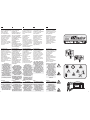 2
2
-
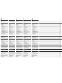 3
3
-
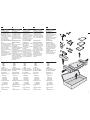 4
4
-
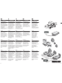 5
5
-
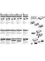 6
6
-
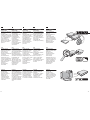 7
7
-
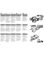 8
8
-
 9
9
-
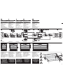 10
10
-
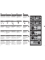 11
11
-
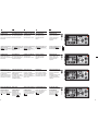 12
12
-
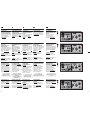 13
13
-
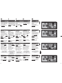 14
14
-
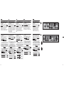 15
15
-
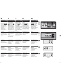 16
16
-
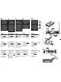 17
17
-
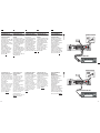 18
18
-
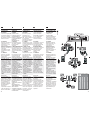 19
19
-
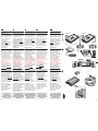 20
20
-
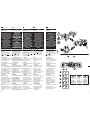 21
21
-
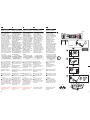 22
22
-
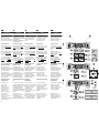 23
23
-
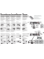 24
24
-
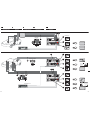 25
25
-
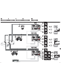 26
26
-
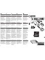 27
27
-
 28
28
-
 29
29
-
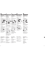 30
30
-
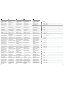 31
31
-
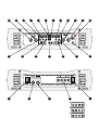 32
32
-
 33
33


Steg K2.01 Manual de usuario
- Categoría
- Altavoces de la barra de sonido
- Tipo
- Manual de usuario
en otros idiomas
- français: Steg K2.01 Manuel utilisateur
- italiano: Steg K2.01 Manuale utente
- English: Steg K2.01 User manual
- Deutsch: Steg K2.01 Benutzerhandbuch
Otros documentos
-
Orion CO6004 Ficha de datos
-
Orion CO3002 Manual de usuario
-
Orion Cobalt CO500.1 Manual de usuario
-
Rockford Fosgate P1200.2 Manual de usuario
-
 Rockford Fosgate Car Amplifier 750X Manual de usuario
-
 Rockford Fosgate 851S Instrucciones de operación
-
 Rockford Fosgate Power 1050S Instrucciones de operación
-
 Rockford Fosgate Punch 551X Instrucciones de operación
-
 Rockford Fosgate Punch 501S Instrucciones de operación
-
Rockford Fosgate 150S Manual de usuario


