Audio Design LA-1000MD El manual del propietario
- Categoría
- Amplificadores de audio para automóviles
- Tipo
- El manual del propietario

M
ono
• LA-600M
• LA-1000MD
• LA-2000MD
• LA-3000MD
A
mplifiers
La página se está cargando...

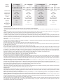
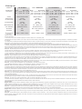
Model
LA-600M LA-1000MD LA-2000MD LA-3000MD
Power
Rating
MAX
400 x 1 @ 4Ω
600 x 1 @ 2Ω
RMS
200 x 1 @ 4Ω
300 x 1 @ 2Ω
MAX
500 x 1 @ 4Ω
750 x 1 @ 2Ω
1000 x 1 @ 1Ω
RMS
250 x 1 @ 4Ω
375 x 1 @ 2Ω
500 x 1 @ 1Ω
MAX
1000 x 1 @ 4Ω
1500 x 1 @ 2Ω
2000 x 1 @ 1Ω
RMS
400 x 1 @ 4Ω
700 x 1 @ 2Ω
1000 x 1 @ 1Ω
MAX
1500 x 1 @ 4Ω
2250 x 1 @ 2Ω
3000 x 1 @ 1Ω
RMS
600 x 1 @ 4Ω
1000 x 1 @ 2Ω
1400 x 1 @ 1Ω
Crossover
12dB/Oct HP/FULL/LPBP 12dB/Oct Low Pass 12dB/Oct Low Pass 12dB/Oct Low Pass
Crossover
Frequency
Variable
40Hz - 150Hz
Variable
35Hz - 250Hz
Variable
35Hz - 250Hz
Variable
35Hz - 250Hz
Subsonic
Filter
Variable
15Hz - 55Hz
Variable
15Hz - 55Hz
Variable
15Hz - 55Hz
Variable
15Hz - 55Hz
Bass Boost
0 to +12dB @ 45Hz
(Remote Included)
0 to +18dB @ 45Hz
(Remote Included)
0 to +18dB @ 45Hz
(Remote Included)
0 to +18dB @ 45Hz
(Remote Included)
Inputs
RCA RCA / Balanced Input RCA / Balanced Input RCA / Balanced Input
Fuse(s)
25A(2) 30A(2) 50A(2) 70A(2)
Dimensions
(LxWxH)
9.8” x 9.4” x 2.3” 11” x 9.4” x 2.3” 13.8” x 9.4” x 2.3” 15” x 9.4” x 2.3”
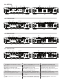
Installation
Preliminary Considerations:
• If you feel unsure about installing this system yourself, have it installed by a qualified technician.
• Think before you drill! Be careful not to cut or drill into gas tanks, fuel lines, brake or hydraulic lines, vacuum lines or electrical wiring when working on any
vehicle.
• Aftermarket amplifiers will put an increased load on the vehicle’s battery and charging system, which can reduce battery and alternator life. It is strongly recom-
mended to upgrade your factory alternator and battery for optimum performance from your new audio system.
CAUTION: Before installation, disconnect the battery negative (-) terminal to prevent damage to the unit, fire and/or possible injury.
1. Choose a mounting location that will be secure and offer plenty of unobstructed space for proper cooling. Then plan the wire routing. Keep RCA cables close
together but isolated from the amplifier’s power cables and any high power auto accessories, especially electric motors. When feeding the wires through the fire
wall or any metal barrier, protect them with plastic or rubber grommets to prevent short circuits. Leave the wires long at this point to adjust for a precise fit at
a later time.
NOTE: Never run wires underneath the vehicle.
2. Prepare the power cable for attachment to the amplifier by stripping 1/2” of insulation from the end of the wire. Insert the bared wire into the B+ terminal and
tighten the setscrew to secure the cable in place.
3. Trim the power cable within 18” of the battery and strip1/2”of insulation from the end of the wire.
4. Strip 1/2” from the battery end of the power cable and crimp a large ring terminal to the cable. Use the ring terminal to connect to the battery positive terminal.
DO NOT install the fuse at this time.
NOTE: ALWAYS protect the battery and electrical system from damage with proper fusing.
5. Prepare the chassis ground by scraping any paint from the metal surface and thoroughly clean the area of all dirt and grease. Strip the end of the wire and
attach a ring connector. Fasten the cable to the chassis using a non-anodized screw and a star washer. Prepare the grounding cable for attachment to the amplifier
by stripping 1/2” of insulation from the other end of the wire. Insert the bared wire into the GND terminal and tighten the setscrew to secure the cable in place.
6. Prepare the REM turn-on wire for connection to the amplifier by stripping 1/2” of insulation from the wire end. Insert the bared wire into the REM terminal
and tighten the setscrew to secure the cable into place. Connect the other end of the REM wire to a switched 12-volt positive source.
NOTE: The switched voltage is usually taken from the source unit’s accessory/remote lead.
7. Securely mount the amplifier to the vehicle or amp rack. Remember: Think before you drill!
NOTE: Be careful not to mount the amplifier on cardboard or plastic panels.
8. Connect the source signal to the amplifier by plugging the RCA cables/high level inputs into the input jacks at the amplifier. Use only one input configuration.
Using both the RCA and High Level inputs will cause undesirable operation. When using a Master/Slave configuration (MD models only), select which amplifier
will be the master, then set the mode switch to Master and connect RCA cables to the input jacks. The Slave amplifier(s); set the mode switch to Slave and connect
RCA cables to the Slave in/out jacks from the Master’s Slave in/out jacks.
NOTE: When using High Level Inputs, if audible engine noise is present, connect the Black wire to chassis ground. If noise is still present, contact your local
authorized dealer or Lightning Audio customer service. When using a Master/Slave setup do not exceed more than two amplifiers. (MD models only)
9. Connect the speakers. Strip the speaker wires 1/2” and insert into the speaker terminal and tighten the setscrew to secure into place. Be sure to maintain
proper speaker polarity. DO NOT chassis ground any of the speaker leads as unstable operation may result.
NOTE: Mono amplifier speaker outputs (A & B) are wired in parallel internally.
10. Perform a final check of the completed system wiring to ensure that all connections are accurate. Check all power and ground connections for frayed wires
and loose connections. Complete the installation by installing the proper value fuse.
Operation
Adjusting Level: To adjust the level setting, turn the amplifier gain level to the lowest setting. Turn the source unit volume up until distortion is audible and then
slowly down until the distortion is inaudible (approximately ¾ volume position). Next, increase the amplifier level setting until once again distortion is audible
and then down slowly until the distortion is inaudible.
NOTE: Proper level setting is done by a trained professional utilizing an oscilloscope. For a more in depth setting procedure, contact Lightning Audio Technical
Support. In a Master/Slave setup ONLY adjustments made to the master amplifier will effect the output. (MD models only)
Adjusting Crossover: Select the appropriate position for the crossover filter switch. Turn the crossover adjustment knob to the lowest setting. With the system
playing at normal listening level, turn the crossover adjustment knob up slowly until the desired crossover point is achieved. Example: subwoofers- low pass with
an 80Hz crossover point and full-range- high pass with a 100Hz crossover point
NOTE: Some models include a subsonic filter with a variable 15-40Hz high pass filter designed to prevent frequencies below the audio range from being applied
to the subwoofer from the amplifier. Set this to your personal preference while listening to the system. In a Master/Slave setup ONLY adjustments made to the
master amplifier will effect the output. (MD models only)
La página se está cargando...
La página se está cargando...
La página se está cargando...

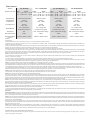
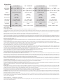
Modello
LA-600M LA-1000MD LA-2000MD LA-3000MD
Potenza
nominale
Massima
400 x 1 @ 4Ω
600 x 1 @ 2Ω
RMS
200 x 1 @ 4Ω
300 x 1 @ 2Ω
Massima
500 x 1 @ 4Ω
750 x 1 @ 2Ω
1000 x 1 @ 1Ω
RMS
250 x 1 @ 4Ω
375 x 1 @ 2Ω
500 x 1 @ 1Ω
Massima
1000 x 1 @ 4Ω
1500 x 1 @ 2Ω
2000 x 1 @ 1Ω
RMS
400 x 1 @ 4Ω
700 x 1 @ 2Ω
1000 x 1 @ 1Ω
Massima
1500 x 1 @ 4Ω
2250 x 1 @ 2Ω
3000 x 1 @ 1Ω
RMS
600 x 1 @ 4Ω
1000 x 1 @ 2Ω
1400 x 1 @ 1Ω
Crossover
12dB/Oct HP/FULL/LPBP 12dB/Oct Passa basso 12dB/Oct Passa basso 12dB/Oct Passa basso
Frequenza
di crossover
Variabile
40Hz - 150Hz
Variabile
35Hz - 250Hz
Variabile
35Hz - 250Hz
Variabile
35Hz - 250Hz
Subsonico
Variabile
15Hz - 55Hz
Variabile
15Hz - 55Hz
Variabile
15Hz - 55Hz
Variabile
15Hz - 55Hz
Amplificazione
bassi
0 to +12dB @ 45Hz
(Comando a distanza incluso)
0 to +18dB @ 45Hz
(Comando a distanza incluso)
0 to +18dB @ 45Hz
(Comando a distanza incluso)
0 to +18dB @ 45Hz
(Comando a distanza incluso)
Ingressi
RCA RCA / Ingressi bilanciati RCA / Ingressi bilanciati RCA / Ingressi bilanciati
Fusibili
25A(2) 30A(2) 50A(2) 70A(2)
Dimensioni
(LUNGxLARGxALT)
249mm x 238mm x 58mm 280mm x 238mm x 58mm 350mm x 238mm x 58mm 520mm x 238mm x 58mm
Italiano
Installazione
Considerazioni preliminari:
• Se si teme di non riuscire a installare il sistema da se stessi, incaricare dell’installazione un tecnico qualificato.
• Pensarci prima di fare fori col trapano! Quando si lavora su un veicolo, fare sempre attenzione a non intaccare o praticare fori nel serbatoio e nelle tubature della benzina, nelle tubature idrauliche
o in quelle dei freni, nelle tubature sottovuoto e nelle linee dell’impianto elettrico.
• Gli amplificatori del mercato secondario aumentano il carico sulla batteria del veicolo e sul suo sistema di carica e riducono la durata della batteria e dell’alternatore. Si consiglia vivamente di
sostituire l’alternatore e la batteria in dotazione di serie per ottenere i migliori risultati dal nuovo impianto audio.
ATTENZIONE: prima dell’installazione, scollegare il terminale negativo (-) della batteria per evitare danni all’unità, incendio e/o il rischio di lesioni.
1. Scegliere per il montaggio una posizione sicura che offre molto spazio libero per un raffreddamento adeguato. Quindi pianificare il percorso dei fili. Tenere i cavi RCA vicini assieme ma isolati
dai cavi di alimentazione dell’amplificatore e da ogni accessorio ad alta potenza, specialmente i motori elettrici. Quando si fanno passare i fili attraverso una parete tagliafiamma, o altra barriera
metallica, si consiglia di proteggerli con guarnizioni di gomma o di plastica per evitare cortocircuiti. A questo punto lasciare che i fili siano di lunghezza abbondante per poterli regolare dopo con
più precisione.
NOTA: non far passare mai i fili sul fondo del veicolo.
2. Predisporre il cavo di alimentazione per collegamento all’amplificatore spelando l’estremità del rivestimento isolante del filo per una lunghezza di 1/2 di pollice (1,3 cm). Inserire il filo denudato
nel terminale B+ e serrare la vite di fermo per garantire che il cavo si mantenga a posto in modo sicuro.
3. Spelare per 1/2 pollice (1,3 cm) l’altra estremità del cavo di alimentazione dell’amplificatore e inserire in un fusibile principale che dovrebbe essere installato entro 18 pollici (45,7 cm) dalla
batteria.
4. Tagliare un pezzo di cavo di alimentazione lungo 18 pollici (45,7 cm) e spelarlo per 1/2 pollice (1,3 cm) a entrambe le estremità. Strozzare un grande terminale ad anello su una estremità del cavo
e fissare in modo sicuro al terminale (+) della batteria. Collegare l’altra estremità al portafusibile principale. NON installare il fusibile a questo punto.
NOTA: Proteggere SEMPRE la batteria e l’impianto elettrico contro i danni utilizzando fusibili adeguati.
5. Preparare il punto di messa a terra sul telaio raschiando la vernice dalla superficie metallica e pulendo a fondo l’area per togliere sporco e grasso. Spelare l’estremità del filo e attaccarvi un con-
nettore ad anello. Fissare il cavo al telaio usando una vite non anodizzata e una rondella dentata. Predisporre il cavo di messa a terra per collegamento all’amplificatore spelando l’altra estremità
del rivestimento isolante del filo per una lunghezza di 1/2 di pollice (1,3 cm). Inserire il filo denudato nel terminale GND e serrare la vite di fermo per garantire che il cavo si mantenga a posto in
modo sicuro.
6. Predisporre il filo di accensione del comando a distanza REM per collegamento all’amplificatore spelando l’estremità del suo rivestimento isolante per una lunghezza di 1/2 di pollice (1,3 cm).
Inserire il filo denudato nel terminale REM e serrare la vite di fermo per garantire che il cavo si mantenga a posto in modo sicuro. Collegare l’altra estremità del filo REM a una fonte commutata
positiva di 12 V.
NOTA: la tensione commutata proviene normalmente dal conduttore sorgente di comando a distanza/accessori dell’unità.
7. Montare l’amplificatore in modo sicuro sul veicolo o in apposito contenitore di alloggio. Ricordare di pensarci prima di fare fori col trapano!
NOTA: prestare attenzione per non montare l’amplificatore su pannelli di cartone o plastica.
8. Collegare il segnale sorgente all’amplificatore inserendo i cavi RCA/ingressi ad alto livello nelle spine d’ingresso dell’amplificatore. Usare una sola configurazione d’ingresso. L’uso di entrambi
gli ingressi RCA e quelli ad alto livello sarà causa di funzionamento non soddisfacente.
NOTA: In presenza di disturbi udibili del motore quando si usano gli ingressi ad alto livello, collegare il filo nero a massa sul telaio. Se i disturbi continuano, mettersi in contatto con il rivenditore
locale o con il servizio di assistenza clienti di Lightning Audio.
9. Collegare i diffusori. Spelare i fili per una lunghezza di 1/2 di pollice (1,3 cm), inserirli nel connettore terminale e serrare le viti di fermo per tenerli a posto in modo sicuro. Accertarsi di mantenere
la corretta polarità del diffusore. NON mettere a terra nessuno dei conduttori dei diffusori perché ciò potrebbe causare un funzionamento instabile.
NOTA: Le uscite monoaurali dell’amplificatore (A e B) sono collegate in parallelo all’interno.
10. Una volta terminato, eseguire un controllo finale del cablaggio dell’impianto per garantire che tutte le connessioni siano state eseguite correttamente. Controllare tutte le connessione di ali-
mentazione emessa a terra per accertarsi che non ci siano logoramenti e allentamenti. Completare l’installazione inserendo il fusibile di corretto valore.
Funzionamento
Regolazione del livello: per regolare l’impostazione di livello, ruotare il livello guadagno sull’impostazione minima. Alzare il volume dell’unità sorgente sino a quando si sente distorsione e quindi
abbassarlo lentamente sino al punto in cui la distorsione non è più udibile (circa 3/4 della posizione del volume) Quindi, aumentare l’impostazione di livello dell’amplificatore sino a rendere udibile di
nuovo la distorsione e poi abbassare lentamente sino a quando la distorsione non è più udibile.
NOTA: l’impostazione del livello coretto è eseguita da parte di un tecnico professionista che utilizza un oscilloscopio. Per una procedura di impostazione più dettagliata, contattare il servizio assistenza
tecnica di Lightning Audio .
Regolazione del crossover: selezionare la posizione adatta per l’interruttore del filtro di crossover. Ruotare la manopola di regolazione del crossover all’impostazione minima. Con il sistema in
funzione al normale livello di ascolto, ruotare la manopola di regolazione per aumentare la frequenza di crossover lentamente fino a raggiungere il punto di crossover desiderato. Esempio: sub-
woofer- passa basso con punto di crossover a 80 Hz e pieno intervallo- passa alto con punto di crossover a 100 Hz.
NOTA: alcuni modelli sono dotati di filtro subsonico incorporato con filtro passa alto variabile da 15 a 40 Hz che evita che le frequenze al di sotto del limite di udibilità siano passate dall’amplificatore
al subwoofer. Impostare il comando sul valore preferito mentre si ascolta.
Informazioni sulla garanzia limitata
I prodotti acquistati dai consumatori da rivenditori autorizzati Lightning Audio situati fuori degli USA sono coperti dalla garanzia offerta dal distributore autorizzato Lightning Audio per ilo Paese
nel quale il prodotto stato acquistato.

L
imited
W
arranty
I
nformation
Lightning Audio offers a limited warranty on products subject to the following terms:
• Length of warranty:
Speakers - One year replacement warranty from date of original purchase - requires proof of purchase.
Amplifiers - One year replacement warranty from date of original purchase - requires proof of purchase.
• What is covered:
This warranty applies only to Lightning Audio products sold to consumers by an authorized Lightning Audio Dealer in the United States
of America. Products purchased by consumers from an authorized Lightning Audio Dealer located outside of the USA are covered by
the authorized Lightning Audio Distributor for the country in which the products were purchased.
• Who is covered:
This warranty covers only the original purchaser of Lightning Audio product purchased from an authorized Lightning Audio Dealer
in the United States. In order to receive service, the purchaser must provide Lightning Audio with a dated copy of the sales receipt
stating the customer name, dealer name and product(s) purchased. Products found to be defective during the warranty period will be
replaced (with a product deemed to be equivalent at Lightning Audio’s sole discretion) by Lightning Audio.
• What is not covered:
1. Damage caused by accident, misuse, abuse, improper installation or operation, water or moisture, excessive heat, theft, or ship-
ping
2. Any cost or expense related to the removal or reinstallation of product
3. Items previously repaired, serviced or modified by an unauthorized service center
4. Any product which has had the serial number defaced, altered, or removed
5. Subsequent damage to other components
6. Any product purchased outside the U.S.
7. Any product not purchased from an authorized Lightning Audio Dealer
• Limit on implied warranties
Any implied warranties of fitness for use and merchantability are limited in duration to the period of the express warranty set forth
above. Some states do not allow limitations on the length of an implied warranty, so this limitation may not apply. No person is autho-
rized to assume for Lightning Audio any other liability in connection with the sale of the product.
• How to obtain service
Defective products should be returned to your local authorized Lightning Audio Dealer for warranty service or, you may call 1-888-
881-8186 for Lightning Audio customer service. You must obtain an RA# (Return Authorization number) prior to returning any
product to Lightning Audio. Return Authorizations are valid for 30 days. You are responsible for the shipment of defective product to
Lightning Audio and you MUST include valid proof of purchase. Mark your RA# clearly on outside of your shipping carton. Products
received without a valid RA# will be refused and returned to sender at sender’s expense.
955 N. Fiesta Blvd, Suite 4
•
Gilbert, Arizona 85233 U.S.A.
•
(800)726-8178
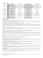
If... Then... Fix...
Amplifier does not turn on B+ or REM not between 10.5 and 15.5 or no voltage present Check the alternator, battery, fuse, and wiring. Repair as
necessary
Amplifier Noise Amplifier is not properly grounded Check wiring and repair as necessary
Turn-On Pop Voltage spike from source unit is entering amplifier’s input Connect a relay turn-on module to REM terminal if pops are
eliminated with no input signal to amplifier
Engine Noise Noise is radiating into signal cables Re-route signal cables away from sources of high current
Troubleshooting
1230-56436-02
08/2010 E.W.R.
Transcripción de documentos
A mplifiers M ono • • • • LA-600M LA-1000MD LA-2000MD LA-3000MD Model LA-600M LA-1000MD MAX RMS MAX RMS 400 x 1 @ 4Ω 200 x 1 @ 4Ω 500 x 1 @ 4Ω 250 x 1 @ 4Ω 600 x 1 @ 2Ω 300 x 1 @ 2Ω 750 x 1 @ 2Ω 375 x 1 @ 2Ω 1000 x 1 @ 1Ω 500 x 1 @ 1Ω Crossover 12dB/Oct HP/FULL/LPBP 12dB/Oct Low Pass Variable Variable Crossover Frequency 40Hz - 150Hz 35Hz - 250Hz Variable Variable Subsonic Filter 15Hz - 55Hz 15Hz - 55Hz 0 to +12dB @ 45Hz 0 to +18dB @ 45Hz Bass Boost (Remote Included) (Remote Included) Inputs RCA RCA / Balanced Input Fuse(s) 25A(2) 30A(2) Power Rating Dimensions (LxWxH) 9.8” x 9.4” x 2.3” 11” x 9.4” x 2.3” LA-2000MD LA-3000MD MAX RMS 1000 x 1 @ 4Ω 400 x 1 @ 4Ω 1500 x 1 @ 2Ω 700 x 1 @ 2Ω 2000 x 1 @ 1Ω 1000 x 1 @ 1Ω 12dB/Oct Low Pass Variable 35Hz - 250Hz Variable 15Hz - 55Hz 0 to +18dB @ 45Hz (Remote Included) RCA / Balanced Input 50A(2) MAX RMS 1500 x 1 @ 4Ω 600 x 1 @ 4Ω 2250 x 1 @ 2Ω 1000 x 1 @ 2Ω 3000 x 1 @ 1Ω 1400 x 1 @ 1Ω 12dB/Oct Low Pass Variable 35Hz - 250Hz Variable 15Hz - 55Hz 0 to +18dB @ 45Hz (Remote Included) RCA / Balanced Input 70A(2) 13.8” x 9.4” x 2.3” 15” x 9.4” x 2.3” Installation Preliminary Considerations: • If you feel unsure about installing this system yourself, have it installed by a qualified technician. • Think before you drill! Be careful not to cut or drill into gas tanks, fuel lines, brake or hydraulic lines, vacuum lines or electrical wiring when working on any vehicle. • Aftermarket amplifiers will put an increased load on the vehicle’s battery and charging system, which can reduce battery and alternator life. It is strongly recommended to upgrade your factory alternator and battery for optimum performance from your new audio system. CAUTION: Before installation, disconnect the battery negative (-) terminal to prevent damage to the unit, fire and/or possible injury. 1. Choose a mounting location that will be secure and offer plenty of unobstructed space for proper cooling. Then plan the wire routing. Keep RCA cables close together but isolated from the amplifier’s power cables and any high power auto accessories, especially electric motors. When feeding the wires through the fire wall or any metal barrier, protect them with plastic or rubber grommets to prevent short circuits. Leave the wires long at this point to adjust for a precise fit at a later time. NOTE: Never run wires underneath the vehicle. 2. Prepare the power cable for attachment to the amplifier by stripping 1/2” of insulation from the end of the wire. Insert the bared wire into the B+ terminal and tighten the setscrew to secure the cable in place. 3. Trim the power cable within 18” of the battery and strip1/2”of insulation from the end of the wire. 4. Strip 1/2” from the battery end of the power cable and crimp a large ring terminal to the cable. Use the ring terminal to connect to the battery positive terminal. DO NOT install the fuse at this time. NOTE: ALWAYS protect the battery and electrical system from damage with proper fusing. 5. Prepare the chassis ground by scraping any paint from the metal surface and thoroughly clean the area of all dirt and grease. Strip the end of the wire and attach a ring connector. Fasten the cable to the chassis using a non-anodized screw and a star washer. Prepare the grounding cable for attachment to the amplifier by stripping 1/2” of insulation from the other end of the wire. Insert the bared wire into the GND terminal and tighten the setscrew to secure the cable in place. 6. Prepare the REM turn-on wire for connection to the amplifier by stripping 1/2” of insulation from the wire end. Insert the bared wire into the REM terminal and tighten the setscrew to secure the cable into place. Connect the other end of the REM wire to a switched 12-volt positive source. NOTE: The switched voltage is usually taken from the source unit’s accessory/remote lead. 7. Securely mount the amplifier to the vehicle or amp rack. Remember: Think before you drill! NOTE: Be careful not to mount the amplifier on cardboard or plastic panels. 8. Connect the source signal to the amplifier by plugging the RCA cables/high level inputs into the input jacks at the amplifier. Use only one input configuration. Using both the RCA and High Level inputs will cause undesirable operation. When using a Master/Slave configuration (MD models only), select which amplifier will be the master, then set the mode switch to Master and connect RCA cables to the input jacks. The Slave amplifier(s); set the mode switch to Slave and connect RCA cables to the Slave in/out jacks from the Master’s Slave in/out jacks. NOTE: When using High Level Inputs, if audible engine noise is present, connect the Black wire to chassis ground. If noise is still present, contact your local authorized dealer or Lightning Audio customer service. When using a Master/Slave setup do not exceed more than two amplifiers. (MD models only) 9. Connect the speakers. Strip the speaker wires 1/2” and insert into the speaker terminal and tighten the setscrew to secure into place. Be sure to maintain proper speaker polarity. DO NOT chassis ground any of the speaker leads as unstable operation may result. NOTE: Mono amplifier speaker outputs (A & B) are wired in parallel internally. 10. Perform a final check of the completed system wiring to ensure that all connections are accurate. Check all power and ground connections for frayed wires and loose connections. Complete the installation by installing the proper value fuse. Operation Adjusting Level: To adjust the level setting, turn the amplifier gain level to the lowest setting. Turn the source unit volume up until distortion is audible and then slowly down until the distortion is inaudible (approximately ¾ volume position). Next, increase the amplifier level setting until once again distortion is audible and then down slowly until the distortion is inaudible. NOTE: Proper level setting is done by a trained professional utilizing an oscilloscope. For a more in depth setting procedure, contact Lightning Audio Technical Support. In a Master/Slave setup ONLY adjustments made to the master amplifier will effect the output. (MD models only) Adjusting Crossover: Select the appropriate position for the crossover filter switch. Turn the crossover adjustment knob to the lowest setting. With the system playing at normal listening level, turn the crossover adjustment knob up slowly until the desired crossover point is achieved. Example: subwoofers- low pass with an 80Hz crossover point and full-range- high pass with a 100Hz crossover point NOTE: Some models include a subsonic filter with a variable 15-40Hz high pass filter designed to prevent frequencies below the audio range from being applied to the subwoofer from the amplifier. Set this to your personal preference while listening to the system. In a Master/Slave setup ONLY adjustments made to the master amplifier will effect the output. (MD models only) Italiano Modello LA-600M LA-1000MD Massima RMS Massima RMS 400 x 1 @ 4Ω 200 x 1 @ 4Ω 500 x 1 @ 4Ω 250 x 1 @ 4Ω 600 x 1 @ 2Ω 300 x 1 @ 2Ω 750 x 1 @ 2Ω 375 x 1 @ 2Ω 1000 x 1 @ 1Ω 500 x 1 @ 1Ω Crossover 12dB/Oct HP/FULL/LPBP 12dB/Oct Passa basso Variabile Variabile Frequenza di crossover 40Hz - 150Hz 35Hz - 250Hz Variabile Variabile Subsonico 15Hz - 55Hz 15Hz - 55Hz 0 to +12dB @ 45Hz 0 to +18dB @ 45Hz Amplificazione bassi (Comando a distanza incluso) (Comando a distanza incluso) Ingressi RCA RCA / Ingressi bilanciati Fusibili 25A(2) 30A(2) Potenza nominale Dimensioni (LUNGxLARGxALT) 249mm x 238mm x 58mm 280mm x 238mm x 58mm LA-2000MD LA-3000MD Massima RMS 1000 x 1 @ 4Ω 400 x 1 @ 4Ω 1500 x 1 @ 2Ω 700 x 1 @ 2Ω 2000 x 1 @ 1Ω 1000 x 1 @ 1Ω 12dB/Oct Passa basso Variabile 35Hz - 250Hz Variabile 15Hz - 55Hz 0 to +18dB @ 45Hz (Comando a distanza incluso) RCA / Ingressi bilanciati 50A(2) Massima RMS 1500 x 1 @ 4Ω 600 x 1 @ 4Ω 2250 x 1 @ 2Ω 1000 x 1 @ 2Ω 3000 x 1 @ 1Ω 1400 x 1 @ 1Ω 12dB/Oct Passa basso Variabile 35Hz - 250Hz Variabile 15Hz - 55Hz 0 to +18dB @ 45Hz (Comando a distanza incluso) RCA / Ingressi bilanciati 70A(2) 350mm x 238mm x 58mm 520mm x 238mm x 58mm Installazione Considerazioni preliminari: • Se si teme di non riuscire a installare il sistema da se stessi, incaricare dell’installazione un tecnico qualificato. • Pensarci prima di fare fori col trapano! Quando si lavora su un veicolo, fare sempre attenzione a non intaccare o praticare fori nel serbatoio e nelle tubature della benzina, nelle tubature idrauliche o in quelle dei freni, nelle tubature sottovuoto e nelle linee dell’impianto elettrico. • Gli amplificatori del mercato secondario aumentano il carico sulla batteria del veicolo e sul suo sistema di carica e riducono la durata della batteria e dell’alternatore. Si consiglia vivamente di sostituire l’alternatore e la batteria in dotazione di serie per ottenere i migliori risultati dal nuovo impianto audio. ATTENZIONE: prima dell’installazione, scollegare il terminale negativo (-) della batteria per evitare danni all’unità, incendio e/o il rischio di lesioni. 1. Scegliere per il montaggio una posizione sicura che offre molto spazio libero per un raffreddamento adeguato. Quindi pianificare il percorso dei fili. Tenere i cavi RCA vicini assieme ma isolati dai cavi di alimentazione dell’amplificatore e da ogni accessorio ad alta potenza, specialmente i motori elettrici. Quando si fanno passare i fili attraverso una parete tagliafiamma, o altra barriera metallica, si consiglia di proteggerli con guarnizioni di gomma o di plastica per evitare cortocircuiti. A questo punto lasciare che i fili siano di lunghezza abbondante per poterli regolare dopo con più precisione. NOTA: non far passare mai i fili sul fondo del veicolo. 2. Predisporre il cavo di alimentazione per collegamento all’amplificatore spelando l’estremità del rivestimento isolante del filo per una lunghezza di 1/2 di pollice (1,3 cm). Inserire il filo denudato nel terminale B+ e serrare la vite di fermo per garantire che il cavo si mantenga a posto in modo sicuro. 3. Spelare per 1/2 pollice (1,3 cm) l’altra estremità del cavo di alimentazione dell’amplificatore e inserire in un fusibile principale che dovrebbe essere installato entro 18 pollici (45,7 cm) dalla batteria. 4. Tagliare un pezzo di cavo di alimentazione lungo 18 pollici (45,7 cm) e spelarlo per 1/2 pollice (1,3 cm) a entrambe le estremità. Strozzare un grande terminale ad anello su una estremità del cavo e fissare in modo sicuro al terminale (+) della batteria. Collegare l’altra estremità al portafusibile principale. NON installare il fusibile a questo punto. NOTA: Proteggere SEMPRE la batteria e l’impianto elettrico contro i danni utilizzando fusibili adeguati. 5. Preparare il punto di messa a terra sul telaio raschiando la vernice dalla superficie metallica e pulendo a fondo l’area per togliere sporco e grasso. Spelare l’estremità del filo e attaccarvi un connettore ad anello. Fissare il cavo al telaio usando una vite non anodizzata e una rondella dentata. Predisporre il cavo di messa a terra per collegamento all’amplificatore spelando l’altra estremità del rivestimento isolante del filo per una lunghezza di 1/2 di pollice (1,3 cm). Inserire il filo denudato nel terminale GND e serrare la vite di fermo per garantire che il cavo si mantenga a posto in modo sicuro. 6. Predisporre il filo di accensione del comando a distanza REM per collegamento all’amplificatore spelando l’estremità del suo rivestimento isolante per una lunghezza di 1/2 di pollice (1,3 cm). Inserire il filo denudato nel terminale REM e serrare la vite di fermo per garantire che il cavo si mantenga a posto in modo sicuro. Collegare l’altra estremità del filo REM a una fonte commutata positiva di 12 V. NOTA: la tensione commutata proviene normalmente dal conduttore sorgente di comando a distanza/accessori dell’unità. 7. Montare l’amplificatore in modo sicuro sul veicolo o in apposito contenitore di alloggio. Ricordare di pensarci prima di fare fori col trapano! NOTA: prestare attenzione per non montare l’amplificatore su pannelli di cartone o plastica. 8. Collegare il segnale sorgente all’amplificatore inserendo i cavi RCA/ingressi ad alto livello nelle spine d’ingresso dell’amplificatore. Usare una sola configurazione d’ingresso. L’uso di entrambi gli ingressi RCA e quelli ad alto livello sarà causa di funzionamento non soddisfacente. NOTA: In presenza di disturbi udibili del motore quando si usano gli ingressi ad alto livello, collegare il filo nero a massa sul telaio. Se i disturbi continuano, mettersi in contatto con il rivenditore locale o con il servizio di assistenza clienti di Lightning Audio. 9. Collegare i diffusori. Spelare i fili per una lunghezza di 1/2 di pollice (1,3 cm), inserirli nel connettore terminale e serrare le viti di fermo per tenerli a posto in modo sicuro. Accertarsi di mantenere la corretta polarità del diffusore. NON mettere a terra nessuno dei conduttori dei diffusori perché ciò potrebbe causare un funzionamento instabile. NOTA: Le uscite monoaurali dell’amplificatore (A e B) sono collegate in parallelo all’interno. 10. Una volta terminato, eseguire un controllo finale del cablaggio dell’impianto per garantire che tutte le connessioni siano state eseguite correttamente. Controllare tutte le connessione di alimentazione emessa a terra per accertarsi che non ci siano logoramenti e allentamenti. Completare l’installazione inserendo il fusibile di corretto valore. Funzionamento Regolazione del livello: per regolare l’impostazione di livello, ruotare il livello guadagno sull’impostazione minima. Alzare il volume dell’unità sorgente sino a quando si sente distorsione e quindi abbassarlo lentamente sino al punto in cui la distorsione non è più udibile (circa 3/4 della posizione del volume) Quindi, aumentare l’impostazione di livello dell’amplificatore sino a rendere udibile di nuovo la distorsione e poi abbassare lentamente sino a quando la distorsione non è più udibile. NOTA: l’impostazione del livello coretto è eseguita da parte di un tecnico professionista che utilizza un oscilloscopio. Per una procedura di impostazione più dettagliata, contattare il servizio assistenza tecnica di Lightning Audio . Regolazione del crossover: selezionare la posizione adatta per l’interruttore del filtro di crossover. Ruotare la manopola di regolazione del crossover all’impostazione minima. Con il sistema in funzione al normale livello di ascolto, ruotare la manopola di regolazione per aumentare la frequenza di crossover lentamente fino a raggiungere il punto di crossover desiderato. Esempio: subwoofer- passa basso con punto di crossover a 80 Hz e pieno intervallo- passa alto con punto di crossover a 100 Hz. NOTA: alcuni modelli sono dotati di filtro subsonico incorporato con filtro passa alto variabile da 15 a 40 Hz che evita che le frequenze al di sotto del limite di udibilità siano passate dall’amplificatore al subwoofer. Impostare il comando sul valore preferito mentre si ascolta. Informazioni sulla garanzia limitata I prodotti acquistati dai consumatori da rivenditori autorizzati Lightning Audio situati fuori degli USA sono coperti dalla garanzia offerta dal distributore autorizzato Lightning Audio per ilo Paese nel quale il prodotto stato acquistato. Troubleshooting If... Then... Fix... Amplifier does not turn on B+ or REM not between 10.5 and 15.5 or no voltage present Check the alternator, battery, fuse, and wiring. Repair as necessary Amplifier Noise Amplifier is not properly grounded Check wiring and repair as necessary Turn-On Pop Voltage spike from source unit is entering amplifier’s input Connect a relay turn-on module to REM terminal if pops are eliminated with no input signal to amplifier Engine Noise Noise is radiating into signal cables Re-route signal cables away from sources of high current L imited W arranty I nformation Lightning Audio offers a limited warranty on products subject to the following terms: • Length of warranty: Speakers - One year replacement warranty from date of original purchase - requires proof of purchase. Amplifiers - One year replacement warranty from date of original purchase - requires proof of purchase. • What is covered: This warranty applies only to Lightning Audio products sold to consumers by an authorized Lightning Audio Dealer in the United States of America. Products purchased by consumers from an authorized Lightning Audio Dealer located outside of the USA are covered by the authorized Lightning Audio Distributor for the country in which the products were purchased. • Who is covered: This warranty covers only the original purchaser of Lightning Audio product purchased from an authorized Lightning Audio Dealer in the United States. In order to receive service, the purchaser must provide Lightning Audio with a dated copy of the sales receipt stating the customer name, dealer name and product(s) purchased. Products found to be defective during the warranty period will be replaced (with a product deemed to be equivalent at Lightning Audio’s sole discretion) by Lightning Audio. • What is not covered: 1. Damage caused by accident, misuse, abuse, improper installation or operation, water or moisture, excessive heat, theft, or shipping 2. Any cost or expense related to the removal or reinstallation of product 3. Items previously repaired, serviced or modified by an unauthorized service center 4. Any product which has had the serial number defaced, altered, or removed 5. Subsequent damage to other components 6. Any product purchased outside the U.S. 7. Any product not purchased from an authorized Lightning Audio Dealer • Limit on implied warranties Any implied warranties of fitness for use and merchantability are limited in duration to the period of the express warranty set forth above. Some states do not allow limitations on the length of an implied warranty, so this limitation may not apply. No person is authorized to assume for Lightning Audio any other liability in connection with the sale of the product. • How to obtain service Defective products should be returned to your local authorized Lightning Audio Dealer for warranty service or, you may call 1-888881-8186 for Lightning Audio customer service. You must obtain an RA# (Return Authorization number) prior to returning any product to Lightning Audio. Return Authorizations are valid for 30 days. You are responsible for the shipment of defective product to Lightning Audio and you MUST include valid proof of purchase. Mark your RA# clearly on outside of your shipping carton. Products received without a valid RA# will be refused and returned to sender at sender’s expense. 955 N. Fiesta Blvd, Suite 4 • Gilbert, Arizona 85233 U.S.A. • (800)726-8178 1230-56436-02 08/2010 E.W.R.-
 1
1
-
 2
2
-
 3
3
-
 4
4
-
 5
5
-
 6
6
-
 7
7
-
 8
8


Audio Design LA-1000MD El manual del propietario
- Categoría
- Amplificadores de audio para automóviles
- Tipo
- El manual del propietario
en otros idiomas
Artículos relacionados

Otros documentos
-
 Lightning Audio LA-8004 Manual de usuario
-
 In Phase IPA 4001D Manual de usuario
-
Bazooka MGA11000H Manual de usuario
-
Rockford Fosgate R1200-1D Manual de usuario
-
Prime R600-4D Installation & Operation Manual
-
 Phoenix Gold SX2 1200W Monoblock Amplifier SX2 Manual de usuario
-
DB Drive SPA1300D Manual de usuario
-
 Rockford Fosgate Power T2500-1bd Instrucciones de operación
-
StetSom DB8000 El manual del propietario
-
 Lightning Audio LA-1000MDMINI Manual de usuario


