Genius FALCON M El manual del propietario
- Tipo
- El manual del propietario

FALCON M
FALCON M

ITALIANO
AVVERTENZE PER L’INSTALLATORE
OBBLIGHI GENERALI PER LA SICUREZZA
ATTENZIONE! È importante per la sicurezza delle persone seguire attentamente
tutta l’istruzione. Una errata installazione o un errato uso del prodotto può
portare a gravi danni alle persone.
Leggere attentamente le istruzioni prima di iniziare l’installazione del prodotto.
I materiali dell’imballaggio (plastica, polistirolo, ecc.) non devono essere lasciati
alla portata dei bambini in quanto potenziali fonti di pericolo.
Conservare le istruzioni per riferimenti futuri.
Questo prodotto è stato progettato e costruito esclusivamente per l’utilizzo indicato
in questa documentazione. Qualsiasi altro utilizzo non espressamente indicato po-
trebbe pregiudicare l’integrità del prodotto e/o rappresentare fonte di pericolo.
GENIUS declina qualsiasi responsabilità derivata dall’uso improprio o diverso da
quello per cui l’automatismo è destinato.
Non installare l’apparecchio in atmosfera esplosiva: la presenza di gas o fumi
infiammabili costituisce un grave pericolo per la sicurezza.
Gli elementi costruttivi meccanici devono essere in accordo con quanto stabilito
dalle Norme EN 12604 e EN 12605.
Per i Paesi extra-CEE, oltre ai riferimenti normativi nazionali, per ottenere un livello di
sicurezza adeguato, devono essere seguite le Norme sopra riportate.
GENIUS non è responsabile dell’inosservanza della Buona Tecnica nella costruzione
delle chiusure da motorizzare, nonché delle deformazioni che dovessero intervenire
nell’utilizzo.
L’installazione deve essere effettuata nell’osservanza delle Norme EN 12453 e EN
12445. Il livello di sicurezza dell’automazione deve essere C+D.
Prima di effettuare qualsiasi intervento sull’impianto, togliere l’alimentazione elettrica
e scollegare le batterie.
Prevedere sulla rete di alimentazione dell’automazione un interruttore onnipolare
con distanza d’apertura dei contatti uguale o superiore a 3 mm. È consigliabile
l’uso di un magnetotermico da 6A con interruzione onnipolare.
Verificare che a monte dell’impianto vi sia un interruttore differenziale con soglia
da 0,03 A.
Verificare che l’impianto di terra sia realizzato a regola d’arte e collegarvi le parti
metalliche della chiusura.
L’automazione dispone di una sicurezza intrinseca antischiacciamento costituita
da un controllo di coppia. E’ comunque necessario verificarne la sogli di intervento
secondo quanto previsto dalle Norme indicate al punto 10.
I dispositivi di sicurezza (norma EN 12978) permettono di proteggere eventuali
aree di pericolo da Rischi meccanici di movimento, come ad Es. schiacciamento,
convogliamento, cesoiamento.
Per ogni impianto è consigliato l’utilizzo di almeno una segnalazione luminosa non-
ché di un cartello di segnalazione fissato adeguatamente sulla struttura dell’infisso,
oltre ai dispositivi citati al punto “16”.
GENIUS declina ogni responsabilità ai fini della sicurezza e del buon funzionamento
dell’automazione, in caso vengano utilizzati componenti dell’impianto non di
produzione GENIUS.
Per la manutenzione utilizzare esclusivamente parti originali GENIUS.
Non eseguire alcuna modifica sui componenti facenti parte del sistema d’auto-
mazione.
L’installatore deve fornire tutte le informazioni relative al funzionamento manuale
del sistema in caso di emergenza e consegnare all’Utente utilizzatore dell’impianto
il libretto d’avvertenze allegato al prodotto.
Non permettere ai bambini o persone di sostare nelle vicinanze del prodotto du-
rante il funzionamento.
Tenere fuori dalla portata dei bambini radiocomandi o qualsiasi altro datore di
impulso, per evitare che l’automazione possa essere azionata involontariamente.
Il transito tra le ante deve avvenire solo a cancello completamente aperto.
L’utente utilizzatore deve astenersi da qualsiasi tentativo di riparazione o d’intervento
e deve rivolgersi solo ed esclusivamente a personale qualificato GENIUS o centri
d’assistenza GENIUS.
Tutto quello che non è previsto espressamente in queste istruzioni non è permes-
so.
ENGLISH
IMPORTANT NOTICE FOR THE INSTALLER
GENERAL SAFETY REGULATIONS
ATTENTION! To ensure the safety of people, it is important that you read all the
following instructions. Incorrect installation or incorrect use of the product
could cause serious harm to people.
Carefully read the instructions before beginning to install the product.
Do not leave packing materials (plastic, polystyrene, etc.) within reach of children
as such materials are potential sources of danger.
Store these instructions for future reference.
This product was designed and built strictly for the use indicated in this documen-
tation. Any other use, not expressly indicated here, could compromise the good
condition/operation of the product and/or be a source of danger.
GENIUS declines all liability caused by improper use or use other than that for which
the automated system was intended.
Do not install the equipment in an explosive atmosphere: the presence of inflam-
mable gas or fumes is a serious danger to safety.
The mechanical parts must conform to the provisions of Standards EN 12604 and
EN 12605.
For non-EU countries, to obtain an adequate level of safety, the Standards mentioned
above must be observed, in addition to national legal regulations.
GENIUS is not responsible for failure to observe Good Technique in the construction
of the closing elements to be motorised, or for any deformation that may occur
during use.
The installation must conform to Standards EN 12453 and EN 12445. The safety level
of the automated system must be C+D.
Before attempting any job on the system, cut out electrical power and disconnect
the batteries.
The mains power supply of the automated system must be fitted with an all-pole
switch with contact opening distance of 3mm or greater. Use of a 6A thermal breaker
with all-pole circuit break is recommended.
Make sure that a differential switch with threshold of 0.03 A is fitted upstream of
the system.
Make sure that the earthing system is perfectly constructed, and connect metal
parts of the means of the closure to it.
1.
2.
3.
4.
5.
6.
7.
8.
9.
10.
11.
12.
13.
14.
15.
16.
17.
18.
19.
20.
21.
22.
23.
24.
25.
26.
1.
2.
3.
4.
5.
6.
7.
8.
9.
10.
11.
12.
13.
14.
The automated system is supplied with an intrinsic anti-crushing safety device con-
sisting of a torque control. Nevertheless, its tripping threshold must be checked as
specified in the Standards indicated at point 10.
The safety devices (EN 12978 standard) protect any danger areas against mecha-
nical movement Risks, such as crushing, dragging, and shearing.
Use of at least one indicator-light is recommended for every system, as well as a
warning sign adequately secured to the frame structure, in addition to the devices
mentioned at point “16”.
GENIUS declines all liability as concerns safety and efficient operation of the auto-
mated system, if system components not produced by GENIUS are used.
For maintenance, strictly use original parts by GENIUS.
Do not in any way modify the components of the automated system.
The installer shall supply all information concerning manual operation of the system
in case of an emergency, and shall hand over to the user the warnings handbook
supplied with the product.
Do not allow children or adults to stay near the product while it is operating.
Keep remote controls or other pulse generators away from children, to prevent the
automated system from being activated involuntarily.
Transit through the leaves is allowed only when the gate is fully open.
The User must not in any way attempt to repair or to take direct action and must
solely contact qualified GENIUS personnel or GENIUS service centres.
Anything not expressly specified in these instructions is not permitted.
FRANÇAIS
CONSIGNES POUR L’INSTALLATEUR
RÈGLES DE SÉCURITÉ
ATTENTION! Il est important, pour la sécurité des personnes, de suivre à la lettre
toutes les instructions. Une installation erronée ou un usage erroné du produit
peut entraîner de graves conséquences pour les personnes.
Lire attentivement les instructions avant d’installer le produit.
Les matériaux d’emballage (matière plastique, polystyrène, etc.) ne doivent pas
être laissés à la portée des enfants car ils constituent des sources potentielles de
danger.
Conserver les instructions pour les références futures.
Ce produit a été conçu et construit exclusivement pour l’usage indiqué dans cette
documentation. Toute autre utilisation non expressément indiquée pourrait compro-
mettre l’intégrité du produit et/ou représenter une source de danger.
GENIUS décline toute responsabilité qui dériverait d’usage impropre ou différent de
celui auquel l’automatisme est destiné.
Ne pas installer l’appareil dans une atmosphère explosive: la présence de gaz ou
de fumées inflammables constitue un grave danger pour la sécurité.
Les composants mécaniques doivent répondre aux prescriptions des Normes EN
12604 et EN 12605.
Pour les Pays extra-CEE, l’obtention d’un niveau de sécurité approprié exige non
seulement le respect des normes nationales, mais également le respect des Normes
susmentionnées.
GENIUS n’est pas responsable du non-respect de la Bonne Technique dans la con-
struction des fermetures à motoriser, ni des déformations qui pourraient intervenir
lors de l’utilisation.
L’installation doit être effectuée conformément aux Normes EN 12453 et EN 12445.
Le niveau de sécurité de l’automatisme doit être C+D.
Couper l’alimentation électrique et déconnecter la batterie avant toute interven-
tion sur l’installation.
Prévoir, sur le secteur d’alimentation de l’automatisme, un interrupteur omnipolaire
avec une distance d’ouverture des contacts égale ou supérieure à 3 mm. On re-
commande d’utiliser un magnétothermique de 6A avec interruption omnipolaire.
Vérifier qu’il y ait, en amont de l’installation, un interrupteur différentiel avec un
seuil de 0,03 A.
Vérifier que la mise à terre est réalisée selon les règles de l’art et y connecter les
pièces métalliques de la fermeture.
L’automatisme dispose d’une sécurité intrinsèque anti-écrasement, formée d’un
contrôle du couple. Il est toutefois nécessaire d’en vérifier le seuil d’intervention
suivant les prescriptions des Normes indiquées au point 10.
Les dispositifs de sécurité (norme EN 12978) permettent de protéger des zones éven-
tuellement dangereuses contre les Risques mécaniques du mouvement, comme
l’écrasement, l’acheminement, le cisaillement.
On recommande que toute installation soit doté au moins d’une signalisation lumi-
neuse, d’un panneau de signalisation fixé, de manière appropriée, sur la structure
de la fermeture, ainsi que des dispositifs cités au point “16”.
GENIUS décline toute responsabilité quant à la sécurité et au bon fonctionnement
de l’automatisme si les composants utilisés dans l’installation n’appartiennent pas
à la production GENIUS.
Utiliser exclusivement, pour l’entretien, des pièces GENIUS originales.
Ne jamais modifier les composants faisant partie du système d’automatisme.
L’installateur doit fournir toutes les informations relatives au fonctionnement manuel
du système en cas d’urgence et remettre à l’Usager qui utilise l’installation les “In-
structions pour l’Usager” fournies avec le produit.
Interdire aux enfants ou aux tiers de stationner près du produit durant le fonction-
nement.
Eloigner de la portée des enfants les radiocommandes ou tout autre générateur
d’impulsions, pour éviter tout actionnement involontaire de l’automatisme.
Le transit entre les vantaux ne doit avoir lieu que lorsque le portail est complète-
ment ouvert.
L’utilisateur doit s’abstenir de toute tentative de réparation ou d’intervention et
doit s’adresser uniquement et exclusivement au personnel qualifié GENIUS ou aux
centres d’assistance GENIUS.
Tout ce qui n’est pas prévu expressément dans ces instructions est interdit.
ESPAÑOL
ADVERTENCIAS PARA EL INSTALADOR
REGLAS GENERALES PARA LA SEGURIDAD
ATENCION! Es sumamente importante para la seguridad de las personas seguir
atentamente las presentes instrucciones. Una instalación incorrecta o un uso
impropio del producto puede causar graves daños a las personas.
Lean detenidamente las instrucciones antes de instalar el producto.
Los materiales del embalaje (plástico, poliestireno, etc.) no deben dejarse al alcance
de los niños, ya que constituyen fuentes potenciales de peligro.
Guarden las instrucciones para futuras consultas.
15.
16.
17.
18.
19.
20.
21.
22.
23.
24.
25.
26.
1.
2.
3.
4.
5.
6.
7.
8.
9.
10.
11.
12.
13.
14.
15.
16.
17.
18.
19.
20.
21.
22.
23.
24.
25.
26.
1.
2.
3.

1
ITALIANO
DICHIARAZIONE CE DI CONFORMITÁ
Fabbricante: GENIUS S.p.A.
Indirizzo: Via Padre Elzi, 32 - 24050 - Grassobbio- Bergamo - ITALIA
Dichiara che: L’operatore mod. FALCON M
• è costruito per essere incorporato in una macchina o per essere assemblato con altri macchinari per costituire una macchina ai sensi della Direttiva
98/37/CE;
• è conforme ai requisiti essenziali di sicurezza delle seguenti altre direttive CEE:
73/23/CEE e successiva modifica 93/68/CEE.
89/336/CEE e successiva modifica 92/31/CEE e 93/68/CEE
inoltre dichiara che non è consentito mettere in servizio il macchinario fino a che la macchina in cui sarà incorporato o di cui diverrà componente sia
stata identificata e ne sia stata dichiarata la conformità alle condizioni della Direttiva 98/37/CE.
Grassobbio, 10-11-2006
L’Amministratore Delegato
D. Gianantoni
Note per la lettura dell’istruzione
Leggere completamente questo manuale di installazione prima di iniziare l’installazione del prodotto.
Il simbolo evidenzia note importanti per la sicurezza delle persone e l’integrità dell’automazione.
Il simbolo richiama l’attenzione su note riguardanti le caratteristiche od il funzionamento del prodotto.
INDICE
1. DESCRIZIONE E CARATTERISTICHE TECNICHE pag.2
2. DIMENSIONI pag.2
3. CURVA DI MASSIMO UTILIZZO pag.2
4. PREDISPOSIZIONI ELETTRICHE (impianto standard) pag.2
5. INSTALLAZIONE DELL’AUTOMAZIONE pag.3
5.1. VERIFICHE PRELIMINARI pag.3
5.2. MURATURA DELLA PIASTRA DI FONDAZIONE pag.3
5.3. INSTALLAZIONE MECCANICA pag.3
5.4. MONTAGGIO DELLA CREMAGLIERA pag.3
6. MESSA IN FUNZIONE pag.4
6.1. COLLEGAMENTO SCHEDA ELETTRONICA pag.4
6.2. POSIZIONAMENTO DEI FINECORSA pag.4
7. PROVA DELL’AUTOMAZIONE pag.5
8. FUNZIONAMENTO MANUALE pag.5
9. RIPRISTINO DEL FUNZIONAMENTO NORMALE pag.5
10. APPLICAZIONI PARTICOLARI pag.5
11. MANUTENZIONE pag.5
12. RIPARAZIONI pag.5
13. ACCESSORI pag.5

2
ITALIANO
2. DIMENSIONI
3. CURVA DI MASSIMO UTILIZZO
La curva consente di individuare
il tempo massimo di lavoro (T)
in funzione della frequenza di
utilizzo (F).
Con riferimento alla Norma IEC
34-1, il motoriduttore FALCON
con un tipo di servizio S3, può
funzionare alla frequenza d’utiliz-
zo del 40%.
Per garantire il buon funziona-
mento è necessario operare nel
campo di lavoro sotto la curva.
Importante: La curva è
ottenuta alla temperatu-
ra di 20 °C. L’esposizione
all’irraggiamento solare
diretto può determi-
nare diminuzioni della
frequenza d’utilizzo fino
al 20%.
Calcolo della frequenza d’utilizzo
E’ la percentuale del tempo di lavoro effettivo (apertura + chiusura)
rispetto al tempo totale del ciclo (apertura + chiusura + tempi sosta).
La formula di calcolo è la seguente:
Ta + Tc
% F = X 100
Ta + Tc + Tp + Ti
dove:
Ta = tempo di apertura
Tc = tempo di chiusura
Tp = tempo di pausa
Ti = tempo di intervallo tra un ciclo completo e l’altro
4. PREDISPOSIZIONI ELETTRICHE (impianto standard)
AUTOMAZIONE FALCON
Le presenti istruzioni sono valide per i seguenti modelli:
FALCON 14 M - FALCON 14 MC - FALCON 20 M- FALCON 20 MC - FALCON
15 M - FALCON 15 MC - FALCON 20 M 3PH
Il motoriduttore FALCON per cancelli scorrevoli è un operatore elet-
tromeccanico che trasmette il movimento all’anta scorrevole tramite
un pignone a cremagliera o catena accoppiato opportunamente al
cancello.
Il sistema irreversibile garantisce il blocco meccanico del cancello
quando il motore non è in funzione e quindi non occorre installare alcuna
serratura.
Il motoriduttore non è dotato di una frizione meccanica e quindi
necessita di una apparecchiatura di comando con frizione
elettronica regolabile che garantisce la necessaria sicurezza
antischiacciamento.
Un comodo sblocco manuale a chiave personalizzata rende manovrabi-
le il cancello in caso di black-out o disservizio.
Nei motoriduttori versione “C” l’apparecchiatura elettronica di comando
è alloggiata all’interno dell’operatore.
Il motoriduttore FALCON è stato progettato e costruito per control-
lare l’accesso veicolare. Evitare qualsiasi altro diverso utilizzo.
1. DESCRIZIONE E CARATTERISTICHE TECNICHE
MODELLO
14 M
14 MC
20 M
20 MC
15 M
15 MC
20 M
3Ph
Alimentazione (+6% -10%)
230 V~
50 Hz
115 V~
60 Hz
400 V~
50Hz
Potenza assorbita (W) 650 800 710 840
Corrente assorbita (A) 2.8 3.5 6.7 2.2
Motore elettrico (giri/min.) 1400 1700 1400
Condensatore di spunto (µF) 16 20 60 /
Spinta sul pignone (daN) 110 150 130 185
Coppia (Nm) 35 45 38 60
Termoprotezione (°C) 140 /
Peso anta max. (Kg) 1400 2000 1500 2000
Tipo di pignone Z 16 modulo 4
Velocità del cancello (m/min.) 10 11 10
Lunghezza max. cancello (m) 20
Tipo di finecorsa Magnetico
Tipo di frizione
Controllo di coppia elettronico
(Vedi centrale)
Frequenza d’utilizzo (vedi grafico) S3 - 40%
S3
50%
Temperatura ambiente (°C) -20 ÷ +55
Peso del motoriduttore (Kg) 14 15
Grado di protezione IP 44
Dimensioni operatore Vedi fig. 2
Piastra di fondazione
Motoriduttore
Contenitore ed apparecchiatura elettronica
(Solo nelle versioni “C”)
Sensore magnetico
Pignone
Manopola di sblocco con chiave
Asole e dadi di fissaggio
Protezioni laterali
Carter di copertura
Pos. Descrizione Cavo di collegamento
Motoriduttore
3x2.5 mm
2
(230/115V~)
4x2.5 mm
2
(400V~)
Trasmettitore fotocellule 2x0.5 mm
2
(TX)
Ricevitore fotocellule 4x0.5 mm
2
(RX)
Selettore a chiave 2x0.5 mm
2
Lampeggiante 2x1.5 mm
2
Ricevente esterna (optional) 3x0.5 mm
2
Fig. 1
Fig. 2
Fig. 3

3
ITALIANO
5. INSTALLAZIONE DELL’AUTOMAZIONE
5.1. VERIFICHE PRELIMINARI
Per la sicurezza e per un corretto funzionamento dell’automazione, verifi-
care l’esistenza dei seguenti requisiti:
• La struttura del cancello deve essere idonea per essere automatizzata.
In particolare si richiede che il diametro delle ruote sia rapportato
al peso del cancello da automatizzare, che sia presente una guida
superiore e vi siano degli arresti meccanici di finecorsa per evitare
deragliamenti del cancello.
• Le caratteristiche del terreno devono garantire una sufficiente tenuta
del plinto di fondazione.
• Nella zona di scavo del plinto non devono essere presenti tubazioni o
cavi elettrici.
• Se il motoriduttore si trova esposto al passaggio di veicoli, possibilmente
prevedere adeguate protezioni contro urti accidentali.
• Verificare l’esistenza di una efficiente presa di terra per il collegamento
del motoriduttore.
• Verificare che attorno all’operatore rimanga uno spazio adeguato per
poter eseguire in modo agevole tutte le operazioni necessarie all’in-
stallazione ed alle successive manutenzioni.
5.2. MURATURA DELLA PIASTRA DI FONDAZIONE
1. Assemblare la piastra di fondazio-
ne come da Fig. 4.
2. La piastra di fondazione deve es-
sere posizionata come da Fig. 5
(chiusura destra) o Fig. 6 (chiusu-
ra sinistra) per garantire il corretto
ingranamento tra il pignone e la
cremagliera.
Nel posizionare la piastra
lasciare il foro Ø 80 previsto
per il passaggio guaine a
sinistra, come in Figg. 5-6
rif. .
5.3. INSTALLAZIONE MECCANICA
Togliere il coperchio motore svitando completamente le 2 viti di fissag-
gio superiori (Fig.8 rif.).
Ruotare il coperchio di circa 30° e tirare verso l’alto.
Sfilare le 2 protezioni laterali (Fig.8 rif.).
Collocare l’operatore sulla piastra
utilizzando le rondelle e i dadi in
dotazione come da Fig.9.
Durante tale operazione fare
passare i cavi attraverso
l’apposita fessura presente nel
corpo riduttore dell’operatore.
Registrare l’altezza dei piedini e la
distanza dal cancello facendo
riferimento a Fig. 10.
Operazione necessaria per il
corretto fissaggio della cre-
magliera e per conservare in
futuro la possibilità di eseguire
eventuali nuove regolazioni in
altezza del motore.
Stringere le viti di fissaggio del motoriduttore.
Predisporre l’operatore per il funzionamento manuale come da para-
grafo 8.
5.4. MONTAGGIO DELLA CREMAGLIERA
5.4.1. CREMAGLIERA DI ACCIAIO A SALDARE (FIG.11)
Montare i tre nottolini filettati sull’elemento
della cremagliera posizionandoli nella
parte superiore dell’asola. In tale modo il
gioco sull’asola consentirà nel tempo le
eventuali regolazioni.
Portare manualmente l’anta in posizione
di apertura.
Appoggiare sul pignone il primo pezzo di
cremagliera a livello e saldare il nottolino
filettato sul cancello come indicato in
Fig.13.
Muovere manualmente il cancello, verificando che la cremagliera sia
in appoggio sul pignone e saldare il secondo e il terzo nottolino.
Accostare un altro elemento di cremagliera al precedente utilizzando,
per mettere in fase la dentatura dei due elementi, un pezzo di crema-
gliera come indicato in Fig.14 rif. .
Muovere manualmente il cancello e saldare i tre nottolini filettati pro-
seguendo fino alla copertura completa del cancello.
Non lasciare sporgere dal cancello eventuali spezzoni di crema-
gliera in esubero.
3. Eseguire un plinto di fondazione come da Fig. 7 e murare la piastra di
fondazione prevedendo una o più guaine per il passaggio dei cavi
elettrici. Verificare la perfetta orizzontalità della piastra con una livella.
Attendere che il cemento faccia presa.
4. Predisporre i cavi elettrici per il collegamento con gli accessori e l’ali-
mentazione elettrica come da Fig. 3.
Per effettuare agevolmente i collegamenti fare fuoriuscire i cavi
circa 40 cm dal foro (Figg. 5-6 rif. ) della piastra di fondazione.
Fig. 8
Fig. 5
Fig. 6
Fig. 7
Fig. 4
Fig. 9
Fig. 10
Fig. 11

4
ITALIANO
5.4.2. CREMAGLIERA DI ACCIAIO AD AVVITARE (FIG. 12)
Portare manualmente l’anta in posizione
di apertura.
Appoggiare sul pignone il primo pezzo di
cremagliera posizionando il distanlziale
tra la cremagliera stessa ed il bordo del
cancello. Controllare con una bolla l’oriz-
zontalità della cremagliera e segnare
con un pennarello il punto di foratura.
Forare con una punta Ø 6,5 mm e filetta-
re con maschio da M8. Avvitare il bullone.
Muovere manualmente il cancello, veri-
ficando che la cremagliera sia in appoggio sul pignone e ripetere le
operazioni al punto .
Accostare un altro elemento di cremagliera al precedente utilizzando,
per mettere in fase la dentatura dei due elementi, un pezzo di crema-
gliera come indicato in Fig. 14 rif. .
Muovere manualmente il cancello e procedere nelle operazioni di
fissaggio come per il primo elemento, proseguendo fino alla copertu-
ra completa del cancello.
Non lasciare sporgere dal cancello eventuali spezzoni di crema-
gliera in esubero.
Note sull’installazione della cremagliera
• Verificare che durante la corsa
del cancello tutti gli elementi
della cremagliera non vadano
fuori dal pignone.
• Non saldare assolutamente gli
elementi della cremagliera nè ai
distanziali nè tra di loro .
• Terminata l’installazione della
cremagliera, per garantire un
corretto ingranamento con il
pignone, è opportuno abbas-
sare di circa 1,5 mm (Fig.15) la
posizione del motoriduttore.
• Verificare manualmente che il
cancello raggiunga regolarmen-
te le battute di arresto mecca-
niche di finecorsa e che non vi
siano attriti durante la corsa.
• Non utilizzare grasso o altri pro-
dotti lubrificanti tra pignone e
cremagliera.
6. MESSA IN FUNZIONE
6.1. COLLEGAMENTO SCHEDA ELETTRONICA
Prima di effettuare qualsiasi tipo di intervento sulla scheda
(collegamenti, programmazione, manutenzione) togliere sempre
l’alimentazione elettrica.
Seguire i punti 10, 11, 12, 13,14 degli OBBLIGHI GENERALI PER LA SICUREZ-
ZA.
Seguendo le indicazioni di Fig. 3 predisporre i cavi nelle canalizzazioni ed
effettuare i collegamenti elettrici con gli accessori prescelti.
Separare sempre i cavi di alimentazione da quelli di comando e di sicu-
rezza (pulsante, ricevente, fotocellule ecc.). Per evitare qualsiasi disturbo
elettrico utilizzare guaine separate.
6.1.1. MESSA A TERRA
Collegare il cavo di messa a terra come in Fig. 16.
6.1.2. APPARECCHIATURA ELETTRONICA
Nei motoriduttori versione “C” l’apparecchiatura elettronica di comando
è fissata ad un supporto orientabile con coperchio trasparente.
Sul coperchio sono stati posizionati i pulsanti di programmazione della
scheda, questo permette di eseguire la programmazione della scheda
senza dover rimuovere il coperchio.
Per collegare correttamente la centrale attenersi a quanto riportato nelle
specifiche istruzioni.
6.2. POSIZIONAMENTO DEI FINECORSA
Per un corretto posizionamento dei magneti di finecorsa è neces-
sario che la centrale di comando sia installata e correttamente
collegata con tutti gli accessori di comando e sicurezza.
L’operatore è dotato di un finecorsa magnetico, che comanda l’arresto
del moto del cancello nel momento in cui il magnete, fissato nella parte
superiore della cremagliera, attiva il sensore. I magneti forniti con l’ope-
ratore sono appositamente polarizzati ed azionano solo un contatto del
sensore, il contatto di chiusura o quello di apertura. Il magnete che azio-
na il contatto di cancello aperto riporta raffigurato un lucchetto aperto,
viceversa il magnete che attiva il contatto di cancello chiuso riporta il
simbolo di lucchetto chiuso (vedi Fig. 17).
Per posizionare correttamente i due magneti di finecorsa agire come di
seguito:
Le operazioni che sono descritte di seguito sono riferite ad un’in-
stallazione con chiusura sinistra (vedi Fig. 6). Nel caso di un’instal-
lazione con chiusura destra (vedi Fig. 5) è necessario invertire i
due magneti sulla cremagliera.
Assemblare i due magneti come indicato in figura 17.
Predisporre l’operatore per il funzionamento manuale come da para-
grafo 8 ed alimentare il sistema
Portare manualmente il cancello in posizione d’apertura lasciando 4
cm dall’arresto meccanico di finecorsa.
Far scorrere sulla cremagliera il magnete con il lucchetto aperto nella
direzione di apertura, vedi figura 18. Appena il led relativo al finecorsa
di apertura presente sulla scheda si spegne far avanzare il magnete
di altri 10 mm e fissarlo con le apposite viti (Fig. 18 rif. ).
Fig. 13
Fig. 12
Fig. 14
Fig. 15
Fig. 16
Fig. 17

5
ITALIANO
Procedere in modo analogo per il magnete di chiusura.
Portare il cancello circa a metà della sua corsa e ribloccare il sistema
(vedi paragrafo 9).
Prima di inviare un’impulso assicurarsi che il cancello non si possa
muovere manualmente.
Comandare un ciclo completo del cancello per verificare il corretto
intervento del finecorsa.
Per evitare danneggiamenti dell’operatore e/o interruzioni del
funzionamento dell’automazione è necessario lasciare circa 40
mm dagli arresti meccanici di finecorsa.
Controllare che a fine manovra, sia in apertura che in chiusura, il
led del rispettivo finecorsa rimanga attivato (led spento).
Apportare le opportune modifiche alla posizione dei magneti di
finecorsa.
7. PROVA DELL’AUTOMAZIONE
Inserire le protezioni laterali e riposizionare il coperchio motore fissandolo
con le apposite viti (Fig. 19)
Applicare l’adesivo di segnalazione
pericolo sulla parte superiore del coper-
chio (Fig.20).
Procedere alla verifica funzionale
accurata dell’automazione e di tutti gli
accessori ad essa collegati.
Consegnare al Cliente il fascicolo
“Istruzioni per l’uso”, illustrare il corretto
funzionamento e utilizzo del motoridut-
tore ed evidenziare le zone di potenzia-
le pericolo dell’automazione.
8. FUNZIONAMENTO MANUALE
Lo sblocco manuale è un dispositivo che permette di svincolare
l’operatore dal cancello permettendone la movimentazione
manuale.
Prima di agire sul dispositivo di sblocco togliere tensione all’impian-
to agendo sull’interruttore differenziale a monte del motoriduttore.
IL DISPOSITIVO DI SBLOCCO NON SI DEVE CONSIDERARE UN ARRESTO
D’EMERGENZA
Nel caso sia necessario azionare manualmente il cancello a causa di
mancanza di alimentazione elettrica o disservizio dell’automazione, è
necessario agire sul dispositivo di sblocco come segue:
1. Inserire l’apposita chiave in dotazione nella serratura, Fig. 21 Rif. , e
ruotarla in senso orario come indicato in Fig. 21 Rif. .
2. Ruotare il sistema di sblocco in senso orario di circa 180°, come indica-
to in Fig. 21 Rif. .
3. Effettuare manualmente la manovra di apertura o chiusura.
9. RIPRISTINO DEL FUNZIONAMENTO NORMALE
Per evitare che un impulso involontario possa azionare il cancello
durante la manovra , prima di ribloccare l’operatore, togliere
alimentazione all’impianto.
1. Ruotare il sistema di sblocco in senso antiorario di circa 180°, come
indicato in Fig. 22 rif. .
2. Ruotare la chiave in senso antiorario, Fig. 22 rif. , ed estrarla dalla
serratura, come indicato in Fig. 22 rif. .
3. Muovere il cancello fino all’ingranamento dello sblocco.
Prima di ripristinare l’alimentazione al sistema verificare che il can-
cello non si possa muovere manualmente.
10. APPLICAZIONI PARTICOLARI
Non sono previste applicazioni particolari.
Tutto quello che non è descritto in queste istruzioni è espressamente
vietato
11. MANUTENZIONE
Al fine d’assicurare nel tempo un corretto funzionamento ed un costante
livello di sicurezza è opportuno eseguire, con cadenza semestrale, un
controllo generale dell’impianto. Nel fascicolo “Istruzioni per l’uso” è stato
predisposto un modulo per la registrazione degli interventi di manuten-
zione.
Il modulo per la manutenzione allegato ha uno scopo puramente
indicativo, non è escluso che per garantire il corretto funziona-
mento dell’automazione ed un costante livello di sicurezza siano
necessarie operazioni di manutenzione non riportate nel modulo.
12. RIPARAZIONI
L’utente utilizzatore deve astenersi da qualsiasi tentativo di riparazione o
d’intervento e deve rivolgersi solo ed esclusivamente a personale qualifi-
cato GENIUS o centri d’assistenza GENIUS.
13. ACCESSORI
Per gli accessori disponibili vedi catalogo GENIUS.
Fig. 18
Fig. 19
Fig. 20
Fig. 21
Fig. 22

6
ENGLISH
CE DECLARATION OF CONFORMITY
Manufacturer: GENIUS S.p.A.
Address: Via Padre Elzi, 32 - 24050 - Grassobbio- Bergamo - ITALY
Declares that: Operator mod. FALCON M
• is built to be incorporated in a machine or to be assembled with other machinery to create a machine under the provisions of Directive 98/37/EC;
• conforms to the essential safety requirements of the other following EEC directives:
73/23/EEC and subsequent amendment 93/68/EEC.
89/336/EEC and subsequent amendment 92/31/EEC and 93/68/EEC
Furthermore, the manufacturer declares that the machinery must not be put into service until the machine into which it will be incorporated or of which
it will become a part has been identified and its conformity to the conditions of Directive 98/37/EC has been declared.
Grassobbio, 10-11-2006
Managing Director
D. Gianantoni
Notes on reading the instruction
Read this installation manual to the full before you begin installing the product.
The symbol indicates notes that are important for the safety of persons and for the good condition of the automated system.
The symbol draws your attention to the notes on the characteristics and operation of the product.
INDEX
1. DESCRIPTION AND TECHNICAL SPECIFICATIONS page.7
2. DIMENSIONS page.7
3. MAXIMUM USE CURVE page.7
4. ELECTRONIC DEVICES (standard system) page.7
5. INSTALLING THE AUTOMATED SYSTEM page.8
5.1. PRELIMINARY CHECKS page.8
5.2. MASONRY FOR FOUNDATION PLATE page.8
5.3. MECHANICAL INSTALLATION page.8
5.4. INSTALLING THE RACK page.8
6. START-UP page.9
6.1. CONNECTION OF CONTROL BOARD page.9
6.2. POSITIONING THE TRAVEL-LIMIT ELEMENTS page.9
7. AUTOMATED SYSTEM TEST page.10
8. MANUAL OPERATION page.10
9. RESTORING NORMAL OPERATION MODE page.10
10. SPECIAL APPLICATIONS page.10
11. MAINTENANCE page.10
12. REPAIRS page.10
13. ACCESSORIES page.10

7
ENGLISH
2. DIMENSIONS
3. MAXIMUM USE CURVE
The curve makes it possible to
establish maximum work time (T)
according to use frequency (F).
With reference to standard IEC
34-1, the FALCON gearmotor,
with service type S3, can oper-
ate at use frequency of 40%.
To ensure efficient operation,
operate in the work range under
the curve.
Important: The curve is
obtained at a tempera-
ture of 20°C. Exposure to
the direct sun rays can
reduce use frequency
down to 20%.
Calculation of use frequency
The percentage of effective work time (opening + closing) compared to
total time of cycle (opening + closing + pause times).
Calculation formula:
Ta + Tc
% F = X 100
Ta + Tc + Tp + Ti
where:
Ta = opening time
Tc = closing time
Tp = pause time
Ti = interval time between one complete cycle and another
4. ELECTRONIC DEVICES (standard system)
FALCON AUTOMATED SYSTEM
These instructions apply to the following models:
FALCON 14 M - FALCON 14 MC - FALCON 20 M- FALCON 20 MC - FALCON
15 M - FALCON 15 MC - FALCON 20 M 3PH
The FALCON gearmotor for sliding gates is an electro-mechanical opera-
tor which transmits drive to the sliding leaf by a rack and pinion or by a
chain suitably coupled to the gate.
The non-reversing system guarantees mechanical locking of the gate
when the motor is not operating and, therefore, there is no need to install
any lock.
The gearmotor does not have a mechanical clutch and, therefore,
requires a control unit with an adjustable electronic clutch which
guarantees the necessary anti-crushing safety.
A handy manual release with a customised key makes the gate manoeu-
vrable in case of a power cut or trouble.
In the “C” version gearmotors, the electronic control unit is housed inside
the operator.
The FALCON gearmotor was designed and built for controlling
vehicle access. Do not use in any different way.
1. DESCRIPTION AND TECHNICAL SPECIFICATIONS
Foundation plate
Gearmotor
Enclosure and control unit
(In “C” versions only)
Magnetic sensor
Pinion
Release knob with key
Securing slots and nuts
Lateral protective devices
Covering housing
Pos. Description Connection cable
Gearmotor
3x2.5 mm
2
(230/115V~)
4x2.5 mm
2
(400V~)
Photocell transmitter 2x0.5 mm
2
(TX)
Photocell receiver 4x0.5 mm
2
(RX)
Key-operated selector switch 2x0.5 mm
2
Flashing light 2x1.5 mm
2
External receiver (optional) 3x0.5 mm
2
MODEL
14 M
14 MC
20 M
20 MC
15 M
15 MC
20 M
3Ph
Power supply (+6% -10%)
230 V~
50 Hz
115 V~
60 Hz
400 V~
50Hz
Absorbed power (W) 650 800 710 840
Absorbed current (A) 2.8 3.5 6.7 2.2
Electric motor (rpm) 1400 1700 1400
Thrust capacitor (µF) 16 20 60 /
Thrust on pinion (daN) 110 150 130 185
Torque (Nm) 35 45 38 60
Temperature protection (°C) 140 /
Max leaf weight (Kg) 1400 2000 1500 2000
Type of pinion gear Z 16 module 4
Gate speed (m/min) 10 11 10
Max. gate length (m) 20
Type of travel-limit device Magnetic
Type of clutch
Electronic torque control
(See control unit)
Use frequency (see graph) S3 - 40%
S3
50%
Operating ambient temperature (°C) -20 ÷ +55
Weight of gearmotor (Kg) 14 15
Protection class IP 44
Operator dimensions See fig. 2
Fig. 1
Fig. 2
Fig. 3

8
ENGLISH
5. INSTALLING THE AUTOMATED SYSTEM
5.1. PRELIMINARY CHECKS
To ensure safety and an efficiently operating automatic system, make
sure the following conditions are observed:
• The structure of the door must be suitable to be automated. Specifical-
ly, the wheel diameter must be in relation to the weight of the gate to
be automated; an upper guide must be present; travel-limit mechani-
cal stops must be fitted to prevent the gate derailing.
• The soil must permit sufficient stability for the foundation plinth.
• There must be no pipes or electrical cables in the plinth excavation
area.
• If the gearmotor is exposed to passing vehicles, install, if possible, ad-
equate means of protection against accidental impact.
• Check if an efficient earth socket is available for connecting the gear-
motor.
• Make sure that there is sufficient space around the operator to enable
all the installation jobs and subsequent maintenance work to be
smoothly carried out.
5.2. MASONRY FOR FOUNDATION PLATE
1. Assemble the foundation plate as
in Fig. 4.
2. The foundation plate must be
located as shown in Fig. 5 (right
closing) or Fig. 6 (left closing) to
ensure correct meshing between
rack and pinion.
When positioning the plate,
leave the Ø 80 hole for rout-
ing the sheaths on the left, as
shown in Fig. 5-6 ref. .
5.3. MECHANICAL INSTALLATION
Remove the motor cover, fully unscrewing the 2 upper securing screws
(Fig. 8 ref. ).
Rotate the cover by about 30° and pull upward.
Withdraw the 2 lateral protective devices (Fig.8 ref. ).
Fit the operator on the plate, using
the supplied washers and nuts as
shown in Fig.9.
During this operation, route the
cables through the slot on the
operator’s reduction element .
Adjust the height of the feet and the
distance from the gate - refer
to Fig. 10.
This operation is necessary to
secure the rack correctly and
to enable you, in future, to
make any height adjustments
to the motor.
Tighten the gearmotor securing screws.
Prepare the operator for manual operation as described in chapter 8.
5.4. INSTALLING THE RACK
5.4.1. STEEL RACK TO BE WELDED (FIG.11)
Fit the three threaded pawls on the rack
element, positioning them on the upper
part of the slot. In this way the clearance
on the slot will enable any adjustments
long-term.
Manually move the leaf to its opening
position.
Lay the first piece of rack level on the
pinion and weld the threaded pawl on
the gate as shown in Fig.13.
Manually move the gate, checking if the
rack is resting on the pinion and weld the second and third pawls.
Fit another rack element next to the previous one, using a piece of
rack, as shown in Fig.14 ref. , to synchronise the teeth of the two
elements.
Move the gate manually and weld the three threaded pawls. Carry on
like this until you have fully covered the gate.
Do not allow any superfluous sections of rack to project from the
gate.
3. Make a foundation plinth as in Fig. 7 and wall the foundation plate,
providing one or more sheaths for routing the electrical cables. Using
a spirit level, check if the plate is perfectly level. Wait for the cement
to set.
4. Prepare the electrical cables for connection to the accessories and
the electrical power supply as shown in Fig. 3.
To facilitate making the connections, make the cables come out
by about 40 cm from the foundation plate hole (Fig. 5-6 ref. ).
Fig. 8
Fig. 5
Fig. 6
Fig. 7
Fig. 4
Fig. 9
Fig. 10
Fig. 11

9
ENGLISH
5.4.2. STEEL RACK TO BE SCREWED (FIG. 12)
Manually move the leaf to its opening
position.
Rest the first section of rack on the pinion,
positioning the spacer between the rack
and the edge of the gate. Using
a spirit level, check if the rack is horizontal
and mark the perforation point with a
felt-tipped pen.
Drill with a 6.5 mm diameter bit, and
thread with an M8 male element. Screw
the bolt.
Manually move the gate, checking if the rack is resting on the pinion
and repeat the operations in point .
Fit another rack element next to the previous one, using a piece of
rack, as shown in Fig. 14 ref. , to synchronise the teeth of the two
elements.
Move the gate by hand and perform the securing operations as for
the first element, carrying on like this until you have covered the gate
completely.
Do not allow any superfluous sections of rack to project from the
gate.
Notes on installing the rack
• Make sure that, during gate
travel,
all the rack elements do not
come out of the pinion.
• Do not, on any account, weld
the rack elements either to the
spacers or to each other.
• After you have finished install-
ing the rack, to ensure correct
meshing with the pinion, we
advise you to lower the position
of the gearmotor by about 1.5
mm (Fig.15).
• Manually check if the gate cor-
rectly reaches the travel-limit
mechanical stops and if there is
any friction during travel.
• Do not use grease or other lubri-
cants between rack and pinion.
6. START-UP
6.1. CONNECTION OF CONTROL BOARD
Before attempting any work on the board (connections, program-
ming, maintenance), always turn off power.
Observe points 10, 11, 12, 13 and 14 of the GENERAL SAFETY RULES.
Follow the instructions in Fig. 3, route the cables in the raceways and
make the electrical connections to the selected accessories.
Always separate power cables from control and safety cables (push-but-
ton, receiver, photocells, etc.). To prevent any electric noise whatever,
use separate sheaths.
6.1.1. EARTHING
Connect the earthing cable as shown in Fig. 16.
6.1.2. CONTROL UNIT
In the “C” version gearmotors, the electronic control unit is secured to an
adjustable support with a transparent cover.
The board programming push-buttons are located on the cover - this
enables you to program the board without having to remove the cover.
To connect the control unit correctly, follow the specific instructions.
6.2. POSITIONING THE TRAVEL-LIMIT ELEMENTS
To correctly position the travel-limit magnets, the control unit must
first be installed and correctly connected to all the command and
safety accessories.
The operator has a magnetic limit switch, which commands gate motion
to stop when the magnet, which is secured to the upper part of the rack,
activates the sensor. The magnets supplied with the operator are specifi-
cally polarised and activate only one of the sensor’s contacts: the clos-
ing or opening contact. The magnet activating the open gate contact
bears an open padlock symbol, and, vice versa, the magnet activating
the closed gate contact bears the closed padlock symbol (see Fig. 17).
Procedure for correct positioning of the two travel-limit magnets:
The operations described below refer to an installation with left
side closing (see Fig. 6). For installations with right side closing (see
Fig. 5), change over the two magnets on the rack.
Assemble the two magnets as shown in Figure 17.
Set the operator to manual mode operation - as per paragraph 8
- and power up the system
Manually take the gate to opening position, leaving 4 cm from the travel limit
mechanical stop.
Allow the magnet, with the padlock open, to slide , in opening direction on the
rack - see figure 18. As soon as the LED on the board, referring to the opening
limit-switch, goes OFF, take the magnet forward by another 10 mm and fasten
it with the appropriate screws (Fig. 18 ref. )
.
Fig. 13
Fig. 12
Fig. 14
Fig. 15
Fig. 16
Fig. 17

10
ENGLISH
Do likewise for the closing magnet.
Take the gate to about halfway of its travel and relock the system (see
paragraph 9).
Before sending a pulse, make sure that the gate cannot be mo-
ved manually.
Command a complete gate cycle to check if the travel-limit device is
tripping correctly.
To avoid damaging the operator and/or interrupting operation of
the automated system, leave a distance of least 40 mm from the
travel limit mechanical stops.
Make sure that at the end of both the opening and closing ma-
noeuvre, the relevant travel-limit LED stays active (LED OFF).
Make the appropriate modifications to the positions of the travel-limit
magnets.
7. AUTOMATED SYSTEM TEST
Fit the lateral protective devices and re-position the motor cover, secur-
ing it with the appropriate screws (Fig. 19).
Apply the danger sticker on the top of
the cover (Fig. 20).
Check operating efficiency of the
automated system and all accessories
connected to it.
Hand the “Use Instructions” to the
Customer, explain correct operation
and use of the gearmotor, and indicate
the potentially dangerous areas of the
automated system.
8. MANUAL OPERATION
The manual release is a device that makes it possible to disconnect
the operator from the gate, thus enabling manual movement.
Before using the release device, cut power to the system, with the
differential switch upstream of the gearmotor.
THE RELEASE DEVICE MUST NOT BE CONSIDERED AN EMERGENCY STOP
If the gate has to be moved manually due to a power cut or fault of the
automated system, use the release device as follows:
1. Fit the supplied key in the lock, Fig. 21 Ref. , and turn it clockwise as
shown in Fig. 21 Ref. .
2.
Turn the release system clockwise by about 180°, as shown in Fig. 21 Ref. .
3. Open and close the gate manually.
9. RESTORING NORMAL OPERATION MODE
To prevent an involuntary pulse from activating the gate during
the manoeuvre, cut power to the system before re-locking the
operator.
1. Turn the release system anti-clockwise by about 180°, as shown in Fig.
22 ref. .
2. Turn the key anti-clockwise, Fig. 22 ref. , and remove it from the lock,
as shown in Fig. 22 ref. .
3. Move the gate until it meshes to release.
Before powering up the system again, make sure that the gate can-
not be moved manually.
10. SPECIAL APPLICATIONS
There are no special applications.
Anything not expressly specified in these instructions is expressly
prohibited
11. MAINTENANCE
To ensure correct long-term operation and a constant level of safety, we
advise you to generally control the system every 6 months. In the “Use
Instructions” booklet, there is a form for recording maintenance jobs.
The enclosed maintenance form is purely a guideline; it cannot be
ruled out that to guarantee a correctly operating automated sys-
tem and a constant level of safety, maintenance operations not
described in this form may be necessary.
12. REPAIRS
The User must not in any way attempt to repair or to take direct action
and must solely contact qualified GENIUS personnel or GENIUS service
centres.
13. ACCESSORIES
For accessories, see the GENIUS catalogue.
Fig. 18
Fig. 19
Fig. 20
Fig. 21
Fig. 22

11
FRANÇAIS
DÉCLARATION CE DE CONFORMITÉ
Fabricant: GENIUS S.p.A.
Adresse: Via Padre Elzi, 32 - 24050 - Grassobbio- Bergamo - ITALIE
Déclare que: L’opérateur mod. FALCON M
• est construit pour être incorporé à une machine ou pour être assemblé à d’autres machines afin de constituer une machine conforme à la Directive
98/37/CE;
• est conforme aux exigences essentielles de sécurité des directives CEE suivantes:
73/23/CEE et modification 93/68/CEE successive.
89/336/CEE et modifications 92/31/CEE et 93/68/CEE successives
On déclare en outre que la mise en service de la machine est interdite tant que la machine à laquelle elle sera incorporée ou dont elle deviendra un
composant n’a pas été identifiée et déclarée conforme aux conditions de la Directive 98/37/CE.
Grassobbio, le 10-11-2006
L’Administrateur Délégué
D. Gianantoni
Remarques pour la lecture de l’instruction
Lire ce manuel d’installation dans son ensemble avant de commencer l’installation du produit.
Le symbole souligne des remarques importantes pour la sécurité des personnes et le parfait état de l’automatisme.
Le symbole attire l’attention sur des remarques concernant les caractéristiques ou le fonctionnement du produit.
INDEX
1. DESCRIPTION ET CARACTÉRISTIQUES TECHNIQUES page.12
2. DIMENSIONS page.12
3. COURBE D’UTILISATION MAXIMUM page.12
4. DISPOSITIONS ÉLECTRIQUES (installation standard) page.12
5. INSTALLATION DE L’AUTOMATISME page.13
5.1. VÉRIFICATIONS PRÉLIMINAIRES page.13
5.2. SCELLAGE DE LA PLAQUE DE FONDATION page.13
5.3. INSTALLATION MÉCANIQUE page.13
5.4. MONTAGE DE LA CRÉMAILLÈRE page.13
6. MISE EN FONCTION page.14
6.1. CONNEXION DE LA PLATINE ÉLECTRONIQUE page.14
6.2. POSITIONNEMENT DES FINS DE COURSE page.14
7. ESSAI DE L’AUTOMATISME page.15
8. FONCTIONNEMENT MANUEL page.15
9. RÉTABLISSEMENT DU FONCTIONNEMET NORMAL page.15
10. APPLICATIONS SPÉCIALES page.15
11. ENTRETIEN page.15
12. RÉPARATIONS page.15
13. ACCESSOIRES page.15

12
FRANÇAIS
2. DIMENSIONS
3. COURBE D’UTILISATION MAXIMUM
La courbe permet de déterminer
le temps maximum de fonction-
nement (T) en fonction de la
fréquence d’utilisation (F).
D’après la Norme IEC 34-1, le
motoréducteur FALCON avec
un type de service S3, peut fonc-
tionner à la fréquence d’utilisa-
tion de 40%.
Pour garantir le bon fonctionne-
ment, opérer dans le champ de
fonctionnement sous la courbe.
Important: La courbe est
obtenue à la tempéra-
ture de 20°C. L’exposition
aux rayons directs du
soleil peut entraîner des
baisses de la fréquence
d’utilisation jusqu’à 20%.
Calcul de la fréquence d’utilisation
C’est le pourcentage du temps de fonctionnement effectif (ouverture +
fermeture) par rapport au temps total du cycle (ouverture + fermeture +
temps d’arrêt).
La formule de calcul est la suivante:
Ta + Tc
% F = X 100
Ta + Tc + Tp + Ti
où:
Ta = temps d’ouverture
Tc = temps de fermeture
Tp = temps de pause
Ti = temps d’intervalle entre deux cycles complets
4. DISPOSITIONS ÉLECTRIQUES (installation standard)
AUTOMATISME FALCON
Ces instructions sont valables pour les modèles suivants:
FALCON 14 M - FALCON 14 MC - FALCON 20 M- FALCON 20 MC - FALCON
15 M - FALCON 15 MC - FALCON 20 M 3PH
Le motoréducteur FALCON pour portails coulissants est un opérateur
électromécanique qui transmet le mouvement au vantail coulissant par
l’intermédiaire d’un pignon à crémaillère ou à chaîne opportunément
accouplé au portail.
Le système irréversible garantit le blocage mécanique du portail quand
le moteur n’est pas en fonction; il n’est donc pas nécessaire d’installer de
serrure.
Le motoréducteur est dépourvu d’embrayage mécanique; une
armoire de manœuvre à embrayage électronique réglable ga-
rantissant la sécurité anti-écrasement est donc nécessaire.
Un dispositif pratique de déverrouillage manuel à clé personnalisée
permet de manœuvrer le portail en cas de coupure de courant ou de
dysfonctionnement.
Sur les motoréducteurs de la version “C”, l’armoire de manœuvre élec-
tronique est intégrée au corps de l’opérateur.
Le motoréducteur FALCON a été conçu et construit pour contrôler
l’accès des véhicules. Éviter toute autre utilisation.
1. DESCRIPTION ET CARACTÉRISTIQUES TECHNIQUES
MODÈLE
14 M
14 MC
20 M
20 MC
15 M
15 MC
20 M
3Ph
Alimentation (+6% -10%)
230 V~
50 Hz
115 V~
60 Hz
400 V~
50Hz
Puissance absorbée (W) 650 800 710 840
Courant absorbé (A) 2.8 3.5 6.7 2.2
Moteur électrique (tours/min.) 1400 1700 1400
Condensateur de démarrage (µF) 16 20 60 /
Poussée sur le pignon (daN) 110 150 130 185
Couple (Nm) 35 45 38 60
Protection thermique (°C) 140 /
Poids maxi vantail (kg) 1400 2000 1500 2000
Type de pignon Z 16 module 4
Vitesse du portail (m/min) 10 11 10
Longueur maxi portail (m) 20
Type de fin de course Magnétique
Type d’embrayage
Contrôle électronique du couple
(Voir centrale)
Fréquence d’utilisation (voir
graphique)
S3 - 40%
S3
50%
Température de fonctionnement (°C) -20 ÷ +55
Poids du motoréducteur (kg) 14 15
Degré de protection IP 44
Dimensions opérateur Voir fig. 2
Plaque de fondation
Motoréducteur
Boîtier et armoire électronique
(Uniquement les versions “C”)
Capteur magnétique
Pignon
Poignée de déverrouillage à clé
Rainures et écrous de fixation
Protections latérales
Carter de protection
Rep. Description Câble de connexion
Motoréducteur
3x2.5 mm
2
(230/115V~)
4x2.5 mm
2
(400V~)
Émetteur photocellules 2x0.5 mm
2
(TX)
Récepteur photocellules 4x0.5 mm
2
(RX)
Sélecteur à clé 2x0.5 mm
2
Lampe clignotante 2x1.5 mm
2
Récepteur externe (en option) 3x0.5 mm
2
Fig. 1
Fig. 2
Fig. 3

13
FRANÇAIS
5. INSTALLATION DE L’AUTOMATISME
5.1. VÉRIFICATIONS PRÉLIMINAIRES
Pour la sécurité et un fonctionnement correct de l’automatisme, vérifier
la présence des conditions requises suivantes:
• La structure du portail doit être indiquée pour l’automatisation. En parti-
culier, le diamètre des roues doit être proportionnel au poids du portail
à automatiser et, pour éviter les déraillements du portail, prévoir un rail
de guidage supérieur et des arrêts mécaniques de fin de course.
• Les caractéristiques du terrain doivent garantir une tenue suffisante de
la base de fondation.
• La zone du creusement de la base doit être dépourvue de conduites et
de câbles électriques.
• Si le motoréducteur est exposé au passage de véhicules, prévoir si pos-
sible des protections adéquates contre les chocs accidentels.
• Vérifier l’existence d’une prise de terre efficiente pour la connexion du
motoréducteur.
• Vérifier qu’autour de l’opérateur il reste un espace adéquat pour
pouvoir effectuer facilement toutes les opérations nécessaires pour
l’installation et les entretiens successifs.
5.2. SCELLAGE DE LA PLAQUE DE FONDATION
1. Assembler la plaque de fondation
d’après la Fig. 4.
2. Positionner la plaque de fonda-
tion d’après la Fig. 5 (fermeture
à droite) ou la Fig. 6 (fermeture à
gauche) pour garantir un engrè-
nement correct entre le pignon
et la crémaillère.
En positionnant la plaque,
laisser le trou Ø 80 prévu
pour le passage des gaines
à gauche, d’après les Fig.
5-6 réf. .
5.3. INSTALLATION MÉCANIQUE
Enlever le couvercle en dévissant complètement les deux vis de fixa-
tion supérieures (Fig. 8 réf. ).
Tourner le couvercle d’environ 30° et tirer vers le haut.
Extraire les 2 protections latérales (Fig.8 réf. ).
Positionner l’opérateur sur la plaque
en utilisant les rondelles et les
écrous fournis d’après la Fig.9.
Durant cette opération, faire
passer les câbles à travers la
fissure spécifique présente
dans le corps du réducteur de
l’opérateur.
Régler la hauteur des pieds et la
distance du portail en faisant réfé-
rence à la Fig. 10.
Opération nécessaire pour
la fixation correcte de la
crémaillère et pour pouvoir, à
l’avenir, effectuer de nouveaux
réglages éventuels en hauteur
du moteur.
Serrer les vis de fixation du motoréducteur.
Disposer l’opérateur pour le fonctionnement manuel, voir paragraphe
8.
5.4. MONTAGE DE LA CRÉMAILLÈRE
5.4.1. CRÉMAILLÈRE À SOUDER EN ACIER (FIG.11)
a Monter les trois cliquets taraudés sur l’élé-
ment de la crémaillère en les position-
nant dans la partie supérieure de la rainu-
re. Ainsi, le jeu sur la rainure permettra les
éventuels réglages dans le temps.
b Amener manuellement le vantail en posi-
tion d’ouverture.
c Poser sur le pignon le premier élément
de la crémaillère au niveau correct et
souder le cliquet taraudé sur le portail
d’après la Fig.13.
d Actionner le portail manuellement, en vérifiant que la crémaillère est
posée sur le pignon et souder le deuxième et le troisième cliquet.
e Placer un autre élément de la crémaillère à côté du précédent en
utilisant un morceau de crémaillère pour mettre en phase la denture
des deux éléments d’après la Fig.14 réf. a.
f Actionner le portail manuellement et souder les trois cliquets taraudés
en continuant jusqu’à la couverture complète du portail.
Ne pas laisser dépasser du portail d’éventuels morceaux de cré-
maillère en excès.
3. Réaliser une base de fondation d’après la Fig. 7 et sceller la plaque de
fondation en prévoyant une ou plusieurs gaines pour le passage des
câbles électriques. Vérifier l’horizontalité parfaite de la plaque avec
un niveau à bulle. Attendre que le béton fasse prise.
4. Disposer les câbles électriques pour la connexion aux accessoires et
l’alimentation électrique d’après la Fig. 3.
Pour réaliser facilement les connexions, faire sortir les câbles élec-
triques d’environ 40 cm par le trou (Fig. 5-6 réf. )de la plaque de
fondation.
Fig. 8
Fig. 5
Fig. 6
Fig. 7
Fig. 4
Fig. 9
Fig. 10
Fig. 11

14
FRANÇAIS
5.4.2. CRÉMAILLÈRE À VISSER EN ACIER (FIG. 12)
Amener manuellement le vantail en posi-
tion d’ouverture.
Poser sur le pignon le premier élément de
la crémaillère en positionnant l’entretoise
entre la crémaillère et le bord du portail.
Contrôler avec un niveau à bulle l’horizon-
talité de la crémaillère et marquer le trou
de perçage avec un crayon-feutre.
Percer avec un foret de Ø 6,5 mm et
tarauder avec un taraud M8. Visser le
boulon.
Actionner le portail manuellement, en vérifiant que la crémaillère est
posée sur le pignon et répéter les opérations au point .
Placer un autre élément de la crémaillère à côté du précédent en
utilisant un morceau de crémaillère pour mettre en phase la denture
des deux éléments d’après la Fig. 14 réf. .
Actionner le portail manuellement et procéder aux opérations de
fixation comme pour le premier élément en continuant jusqu’à la
couverture complète du portail.
Ne pas laisser dépasser du portail d’éventuels morceaux de cré-
maillère en excès.
Remarques à propos de l’installation de la crémaillère
• Vérifier que durant la course du
portail aucun élément de la cré-
maillère ne sorte du pignon.
• Ne jamais souder les éléments de
la crémaillère ni aux entretoises,
ni les uns aux autres.
• Au terme de l’installation de la
crémaillère, pour garantir un
engrènement correct avec le pi-
gnon, on recommande d’abais-
ser d’environ 1,5 mm (Fig.15) la
position du motoréducteur.
• Vérifier manuellement que le
portail atteint régulièrement les
butées d’arrêt mécaniques de
fin de course et qu’il n’y a pas
de frottements durant la course.
• Ne jamais utiliser de graisse ni
d’autres produits lubrifiants entre
le pignon et la crémaillère.
6. MISE EN FONCTION
6.1. CONNEXION DE LA PLATINE ÉLECTRONIQUE
Avant tout type d’intervention sur la platine (connexions,program
mation, entretien) toujours couper le courant électrique.
Suivre les points 10, 11, 12, 13,14 des PRESCRIPTIONS GÉNÉRALES DE SÉCU-
RITÉ.
En suivant les indications de la Fig. 3, disposer les câbles dans les canali-
sations et réaliser les connexions électriques aux accessoires choisis.
Toujours séparer les câbles d’alimentation des câbles de commande et
de sécurité (bouton-poussoir, récepteur, photocellules, etc.). Utiliser des
gaines séparées pour éviter toute perturbation électrique.
6.1.1. MISE À LA TERRE
Connecter le câble de mise à la terre d’après la Fig. 16.
6.1.2. ARMOIRE ÉLECTRONIQUE
Sur les motoréducteurs de la version “C”, l’armoire de manœuvre électro-
nique est fixée sur un support orientable avec un couvercle transparent.
Sur le couvercle, on a positionné les boutons-poussoirs de programmation
de la platine, pour une utilisation sans devoir enlever le couvercle.
Pour connecter correctement la centrale, suivre les instructions spécifi-
ques.
6.2. POSITIONNEMENT DES FINS DE COURSE
Pour un fonctionnement correct des aimants de fin de course,
la centrale de commande doit être correctement installée et
connectée à tous les accessoires de commande et de sécurité.
L’opérateur est muni d’un fin de course magnétique qui commande l’ar-
rêt du mouvement du portail au moment où l’aimant, fixé dans la partie
supérieure de la crémaillère, active le capteur. Les aimants fournis avec
l’opérateur sont spécialement polarisés et actionnent uniquement un
contact du capteur, le contact de fermeture ou le contact d’ouverture.
Sur l’aimant qui actionne le contact de portail ouvert est reproduit un
cadenas ouvert, vice versa sur l’aimant qui active le contact de portail
fermé est reproduit le symbole d’un cadenas fermé (voir Fig. 17).
Pour positionner correctement les deux aimants de fin de course, agir
comme suit:
Les opérations décrites ci-après concernent une installation avec
la fermeture à gauche (voir Fig. 6). Dans le cas d’une installation
avec la fermeture à droite (voir Fig. 5), inverser les deux aimants
sur la crémaillère..
Assembler les deux aimants d’après la figure 17.
Disposer l’opérateur pour le fonctionnement manuel, d’après le para-
graphe 8, et mettre le système sous tension
Amener manuellement le portail en position d’ouverture en laissant 4 cm à
partir de l’arrêt mécanique de fin de course.
Faire coulisser sur la crémaillère l’aimant avec le cadenas ouvert dans la
direction d’ouverture, voir figure 18. Dès que la LED relative au fin de course
d’ouverture présente sur la platine s’éteint, faire avancer l’aimant de 10 mm
supplémentaires et le fixer avec les vis spécifiques (Fig. 18 réf ).
Fig. 13
Fig. 12
Fig. 14
Fig. 15
Fig. 16
Fig. 17

15
FRANÇAIS
Procéder de la même manière pour l’aimant de fermeture.
Amener le portail environ à la moitié de sa course et bloquer de nou-
veau le système (voir paragraphe 9).
Avant d’envoyer une impulsion, s’assurer que le portail ne peut
pas être actionné manuellement.
Commander un cycle complet du portail pour vérifier l’intervention
correcte du fin de course.
Pour éviter d’endommager l’opérateur et/ou d’interrompre le
fonctionnement de l’automatisme, laisser une distance d’environ
40 mm des arrêts mécaniques de fin de course.
Contrôler qu’en fin de manœuvre, d’ouverture ou de fermeture,
la LED du fin de course respectif reste activée (LED éteinte).
Modifier de façon opportune la position des aimants de fin de course.
7. ESSAI DE L’AUTOMATISME
Monter les protections latérales et repositionner le couvercle du moteur
en le fixant avec les vis spécifiques (Fig. 19)
Appliquer l’autocollant de signalisation
de danger sur la partie supérieure du
couvercle (Fig.20).
Procéder à un contrôle fonctionnel
minutieux de l’automatisme et de tous
les accessoires connectés.
Remettre au Client le dossier “Ins-
tructions pour l’utilisateur”, illustrer le
fonctionnement correct du système
ainsi que l’utilisation du motoréducteur
et signaler les zones de danger potentiel
de l’automatisme.
8. FONCTIONNEMENT MANUEL
Le déverrouillage manuel est un dispositif qui permet de dégager
l’opérateur du portail en en permettant l’actionnement manuel.
Avant d’agir sur le dispositif de déverrouillage, couper le courant sur l’instal-
lation en agissant sur l’interrupteur différentiel en amont du motoréduc-
teur.
LE DISPOSITF DE DÉVERROUILLAGE N’EST PAS UN ARRÊT D’URGENCE
S’il est nécessaire d’actionner manuellement le portail en raison d’une
coupure de courant ou d’un dysfonctionnement de l’automatisme, agir
sur le dispositif de déverrouillage comme suit:
1. Introduire la clé spéciale fournie dans la serrure, Fig. 21 Réf. , et la
tourner en sens horaire d’après la Fig. 21 Réf. .
2. Tourner le système de déverrouillage en sens horaire d’environ 180°,
d’après la Fig. 21 Réf. .
3. Effectuer manuellement la manœuvre d’ouverture ou de fermeture.
9. RÉTABLISSEMENT DU FONCTIONNEMET NORMAL
Pour éviter qu’une impulsion involontaire n’actionne le portail
durant la manœuvre, couper le courant sur l’installation avant de
bloquer de nouveau l’opérateur.
1. Tourner le système de déverrouillage en sens inverse horaire d’environ
180°, d’après la Fig. 22 réf. .
2. Tourner la clé en sens inverse horaire d’après la Fig. 22 réf. , et l’ex-
traire de la serrure d’après la Fig. 22 réf. .
3. Actionner le portail jusqu’à l’engrènement du déverrouillage.
Avant de remettre le système sous tension, vérifier que le portail ne
peut pas être actionné manuellement.
10. APPLICATIONS SPÉCIALES
Aucune application spéciale n’a été prévue.
Tout ce qui n’est pas expressément décrit dans ces instructions est
formellement interdit.
11. ENTRETIEN
Pour assurer un fonctionnement correct et un niveau de sécurité constant
durables, exécuter, tous les six mois, un contrôle général de l’installation.
Avec le dossier “Instructions pour l’utilisateur”, on a disposé un formulaire
pour l’enregistrement des interventions d’entretien.
Le formulaire d’entretien annexé a un objectif purement indicatif; il
n’est pas exclu que pour garantir le fonctionnement correct de
l’automatisme et un niveau de sécurité constant des opérations
d’entretien ne figurant pas sur le formulaire soient nécessaires.
12. RÉPARATIONS
L’utilisateur doit s’abstenir de toute tentative de réparation ou d’inter-
vention et doit s’adresser uniquement et exclusivement à du personnel
qualifié GENIUS ou aux centres d’assistance GENIUS.
13. ACCESSOIRES
Pour les accessoires disponibles, voir catalogue GENIUS.
Fig. 18
Fig. 19
Fig. 20
Fig. 21
Fig. 22

16
ESPAÑOL
DECLARACIÓN CE DE CONFORMIDAD
Fabricante: GENIUS S.p.A.
Dirección: Via Padre Elzi, 32 - 24050 - Grassobbio- Bergamo - ITALIA
Declara que: Operador mod. FALCON M
• ha sido fabricado para ser incorporado en una máquina o para ser ensamblado con otras maquinarias para construir una máquina de conformidad
con la Directiva 98/37/CE;
• cumple con los requisitos esenciales de seguridad de las siguientes directivas CEE:
73/23/CEE y sucesiva modificación 93/68/CEE.
89/336/CEE y sucesiva modificación 92/31/CEE y 93/68/CEE
asimismo declara que no está permitido poner en funcionamiento la maquinaria hasta que la máquina en la que deberá incorporarse o de la cual
será un componente haya sido identificada y se haya declarado su conformidad con las condiciones de la Directiva 98/37/CE.
Grassobbio, 10-11-2006
El Administrador Delegado
D. Gianantoni
Notas para la lectura de las instrucciones
Leer completamente este manual antes de empezar la instalación del producto.
El símbolo destaca notas importantes para la seguridad de las personas y la integridad de la automación.
El símbolo evidencia notas sobre las características o el funcionamiento del producto.
ÍNDICE
1. DESCRIPCIÓN Y CARACTERÍSTICAS TÉCNICAS pág.17
2. DIMENSIONES pág.17
3. CURVA DE MÁXIMA UTILIZACIÓN pág.17
4. PREDISPOSICIONES ELÉCTRICAS (equipo estándar) pág.17
5. INSTALACIÓN DE LA AUTOMACIÓN pág.18
5.1. COMPROBACIONES PREVIAS pág.18
5.2. COLOCACIÓN EN OBRA DE LA PLACA DE CIMENTACIÓN pág.18
5.3. INSTALACIÓN MECÁNICA pág.18
5.4. MONTAJE DE LA CREMALLERA pág.18
6. PUESTA EN FUNCIONAMIENTO pág.19
6.1. CONEXIÓN DE LA TARJETA ELECTRÓNICA pág.19
6.2. POSICIONAMIENTO DE LOS FINALES DE CARRERA pág.19
7. PRUEBA DE LA AUTOMACIÓN pág.20
8. FUNCIONAMIENTO MANUAL pág.20
9.
RESTABLECIMIENTO DEL FUNCIONAMIENTO NORMAL pág.20
10. APLICACIONES ESPECIALES pág.20
11. MANTENIMIENTO pág.20
12. REPARACIONES pág.20
13. ACCESORIOS pág.20

1
ITALIANO
Fig. 1
Fig. 2
Istruzioni per l’uso - Instructions for use - Instructions pour l’usager
- Instrucciones para el uso - Gebrauchsanleitung - Gids voor de
gebruiker
FALCON M
FALCON M
Leggere attentamente le istruzioni prima di utilizzare il prodotto e
conservarle per eventuali necessità future
NORME GENERALI DI SICUREZZA
L’automazione FALCON M, se correttamente installata ed utilizzata,
garantisce un elevato grado di sicurezza. Alcune semplici norme
di comportamento possono evitare inoltre inconvenienti acciden-
tali:
- Non sostare e non permettere a bambini, persone o cose di sostare nel-
le vicinanze dell’automazione, sopprattutto durante il funzionamento.
- Tenere fuori dalla portata dei bambini, radiocomandi o qualsiasi altro
datore d’impulso che possa azionare involontariamente l’automazio-
ne.
- Non permettere ai bambini di giocare con l’automazione.
- Non contrastare volontariamente il movimento del cancello.
- Evitare che rami o arbusti possano interferire col movimento del can-
cello.
- Mantenere efficienti e ben visibili i sistemi di segnalazione luminosa.
- Non tentare di azionare manualmente il cancello se non dopo averlo
sbloccato.
- In caso di malfunzionamenti, sbloccare il cancello per consentire l’ac-
cesso ed attendere l’intervento tecnico di personale qualificato.
- Una volta predisposto il funzionamento manuale, prima di ripristinare il
funzionamento normale, togliere alimentazione elettrica all’impianto.
- Non eseguire alcuna modifica sui componenti facenti parte il sistema
d’automazione.
- Astenersi da qualsiasi tentativo di riparazione o d’intervento diretto e
rivolgersi solo a personale qualificato.
- Far verificare almeno semestralmente l’efficienza dell’automazione,
dei dispositivi di sicurezza e del collegamento di terra da personale
qualificato.
DESCRIZIONE
L’automazione FALCON M è ideale per il controllo di aree di accesso
veicolare in ambito residenziale.
FALCON M per cancelli scorrevoli è un operatore elettromeccanico
che trasmette il movimento all’anta tramite un pignone a cremagliera.
Per il dettagliato comportamento del cancello scorrevole nelle diverse
logiche di funzionamento, fare riferimento al Tecnico d’installazione.
Nelle automazioni sono presenti dispositivi di rilevazione ostacolo
(fotocellule) che impediscono la richiusura del cancello quando un
ostacolo si trova nella zona da loro protetta.
Il sistema garantisce il blocco meccanico quando il motore non è in
funzione e quindi non occorre installare alcuna serratura.
L’apertura manuale è quindi possibile solo intervenendo sull’apposito
sistema di sblocco.
Il motoriduttore è dotato di frizione elettronica regolabile che permette
un uso sicuro dell’automazione.
L’apparecchiatura elettronica è incorporata nel motoriduttore.
Un comodo sblocco manuale rende manovrabile il cancello in caso di
black-out o disservizio.
La segnalazione luminosa indica il movimento in atto del cancello.
CARATTERISTICHE TECNICHE
MODELLO
14 M
14 MC
20 M
20 MC
15 M
15 MC
20 M
3Ph
Alimentazione (+6% -10%)
230 V~
50 Hz
115 V~
60 Hz
400 V~
50Hz
Potenza assorbita (W) 650 800 710 840
Corrente assorbita (A) 2.8 3.5 6.7 2.2
Motore elettrico (giri/min.) 1400 1700 1400
Condensatore di spunto (µF) 16 20 60 /
Spinta sul pignone (daN) 110 150 130 185
Coppia (Nm) 35 45 38 60
•
•
•
•
•
•
•
•
•
•
MODELLO
14 M
14 MC
20 M
20 MC
15 M
15 MC
20 M
3Ph
Termoprotezione (°C) 140 /
Peso anta max. (Kg) 1400 2000 1500 2000
Tipo di pignone Z 16 modulo 4
Velocità del cancello (m/min.) 10 11 10
Lunghezza max. cancello (m) 20
Tipo di finecorsa Magnetico
Tipo di frizione
Controllo di coppia elettronico
(Vedi centrale)
Frequenza d’utilizzo (vedi grafico) S3 - 40%
S3
50%
Temperatura ambiente (°C) -20 ÷ +55
Peso del motoriduttore (Kg) 14 15
Grado di protezione IP 44
FUNZIONAMENTO MANUALE
Lo sblocco manuale è un dispositivo che permette di svincolare
l’operatore dal cancello permettendone la movimentazione
manuale.
Prima di agire sul dispositivo di sblocco togliere tensione all’impian-
to agendo sull’interruttore differenziale a monte del motoriduttore.
IL DISPOSITIVO DI SBLOCCO NON SI DEVE CONSIDERARE UN ARRESTO
D’EMERGENZA
Nel caso sia necessario azionare manualmente il cancello a causa di
mancanza di alimentazione elettrica o disservizio dell’automazione, è
necessario agire sul dispositivo di sblocco come segue:
1. Inserire l’apposita chiave in dotazione nella serratura, Fig. 1 Rif. a, e
ruotarla in senso orario come indicato in Fig. 1 Rif. b.
2. Ruotare il sistema di sblocco in senso orario di circa 180°, come indica-
to in Fig. 1 Rif. c.
3. Effettuare manualmente la manovra di apertura o chiusura.
RIPRISTINO DEL FUNZIONAMENTO NORMALE
Per evitare che un impulso involontario possa azionare il cancello
durante la manovra , prima di ribloccare l’operatore, togliere
alimentazione all’impianto.
1. Ruotare il sistema di sblocco in senso antiorario di circa 180°, come
indicato in Fig. 2 rif. a.
2. Ruotare la chiave in senso antiorario, Fig. 2 rif. b, ed estrarla dalla serra-
tura, come indicato in Fig. 2 rif. c.
3. Muovere il cancello fino all’ingranamento dello sblocco.
Prima di ripristinare l’alimentazione al sistema verificare che il can-
cello non si possa muovere manualmente.
MANUTENZIONE
Al fine d’assicurare nel tempo un corretto funzionamento ed un costante
livello di sicurezza è opportuno eseguire, con cadenza semestrale, un
controllo generale dell’impianto. Nel fascicolo “Istruzioni per l’uso” è stato
predisposto un modulo per la registrazione degli interventi di manuten-
zione.
Il modulo per la manutenzione allegato ha uno scopo puramente
indicativo, non è escluso che per garantire il corretto funziona-
mento dell’automazione ed un costante livello di sicurezza siano
necessarie operazioni di manutenzione non riportate nel modulo.
RIPARAZIONI
L’utente utilizzatore deve astenersi da qualsiasi tentativo di riparazione o
d’intervento e deve rivolgersi solo ed esclusivamente a personale qualifi-
cato GENIUS o centri d’assistenza GENIUS.

2
ENGLISH
Read the instructions carefully before using the product and store
them for future use
GENERAL SAFETY REGULATIONS
If correctly installed and used, the FALCON M automated system
will ensure a high degree of safety. Some simple rules on beha-
viour can prevent accidental trouble:
- Do not stand near the automatic system, and do not allow children,
persons or things to do so, especially when it is operating.
- Keep radio-controls, or any other pulse generators that could involunta-
rily activate the automated system, well away from children.
- Do not allow children to play with the automated system.
- Do not willingly obstruct gate movement.
- Prevent any branches or shrubs from interfering with gate movement.
- Keep the indicator-lights efficient and easy to see.
- Do not attempt to activate the gate by hand unless you have released
it.
- In the event of malfunctions, release the gate to allow access and wait
for qualified technical personnel to do the necessary work.
- When you have set manual operation mode, cut power to the system
before restoring normal operation.
- Do not in any way modify the components of the automated system.
- Do not attempt any kind of repair or direct action whatever and con-
tact qualified personnel only.
- At least every six months: arrange a check by qualified personnel of the
automatic system, safety devices and earth connection.
DESCRIPTION
The FALCON M automated system is ideal for controlling vehicle access
areas in residential environments.
FALCON M for sliding gates is an electro-mechanical operator which
transmits motion to the leaf via a rack and pinion.
For details on sliding gate behaviour in different function logics, consult
the installation Technician.
Automated systems include obstacle detection devices (photocells) that
prevent the gate from closing when there is an obstacle in the area
they protect.
The system ensures mechanical locking when the motor is not operating
and, therefore, installing a lock is unnecessary.
Manual opening is, therefore, only possible by using the release system.
The gearmotor has an adjustable electronic clutch enabling safe use of
the automated system.
The control unit is built into the gearmotor.
A handy manual release facility makes it possible to move the gate in the
event of a power cut or fault.
The warning-light indicates that the gate is currently moving.
TECHNICAL SPECIFICATIONS
MODEL
14 M
14 MC
20 M
20 MC
15 M
15 MC
20 M
3Ph
Power supply (+6% - 10%)
230 V~
50 Hz
115 V~
60 Hz
400 V~
50Hz
Absorbed power (W) 650 800 710 840
Absorbed current (A) 2.8 3.5 6.7 2.2
Electric motor (rpm) 1400 1700 1400
Thrust capacitor (µF) 16 20 60 /
Thrust on pinion (daN) 110 150 130 185
Torque (Nm) 35 45 38 60
MODEL
14 M
14 MC
20 M
20 MC
15 M
15 MC
20 M
3Ph
Temperature protection (°C) 140 /
Max leaf weight (Kg) 1400 2000 1500 2000
Type of pinion gear Z 16 module 4
Gate speed (m/min) 10 11 10
Gate max. length (m) 20
Type of travel-limit device Magnetic
Type of clutch
Electronic torque control
(See control unit)
Use frequency (see graph) S3 - 40%
S3
50%
Operating ambient temperature (°C) -20 ÷ +55
Weight of gearmotor (Kg) 14 15
Protection class IP 44
MANUAL OPERATION
The manual release is a device that makes it possible to disconnect
the operator from the gate, thus enabling manual movement.
Before using the release device, cut power to the system, with the
differential switch upstream of the gearmotor.
THE RELEASE DEVICE MUST NOT BE CONSIDERED AN EMERGENCY STOP
If the gate has to be moved manually due to a power cut or fault of the
automated system, use the release device as follows:
1. Fit the supplied key in the lock, Fig. 1 Ref. a, and turn it clockwise as
shown in Fig. 1 Ref. b.
2. Turn the release system clockwise by about 180°, as shown in Fig. 1 Ref.
c.
3. Open and close the gate manually.
RESTORING NORMAL OPERATION MODE
To prevent an involuntary pulse from activating the gate during
the manoeuvre, cut power to the system before re-locking the
operator.
1. Turn the release system anti-clockwise by about 180°, as shown in Fig.
2 ref. a.
2. Turn the key anti-clockwise, Fig. 2 ref. b, and remove it from the lock, as
shown in Fig. 2 ref. c.
3. Move the gate until it meshes to release.
Before powering up the system again, make sure that the gate can-
not be moved manually.
MAINTENANCE
To ensure correct long-term operation and a constant level of safety, we
advise you to generally control the system every 6 months. In the “UseUse
Instructions” booklet, there is a form for recording maintenance jobs.” booklet, there is a form for recording maintenance jobs.
The enclosed maintenance form is purely a guideline; it cannot be
ruled out that to guarantee a correctly operating automated sy-
stem and a constant level of safety, maintenance operations not
described in this form may be necessary.
REPAIRS
The User must not in any way attempt to repair or to take direct action
and must solely contact qualified GENIUS personnel or GENIUS service
centres.
FRANÇAIS
Lire attentivement les instructions avant d’utiliser le produit et les
conserver pour toute nécessité future éventuelle
PRESCRIPTIONS GÉNÉRALES DE SÉCURITÉ
S’il est correctement installé et utilisé, l’automatisme FALCON M
garantit un haut niveau de sécurité. Par ailleurs, quelques règles
simples de comportement peuvent éviter bien des accidents
- Ne pas stationner et interdire aux enfants, aux personnes et aux cho-
ses
de stationner près de l’automatisme et en particulier durant le
fonctionnement.
- Éloigner de la portée des enfants les radiocommandes ou tout autre
dispositif générateur d’impulsion, pour éviter que l’automatisme ne
soit actionné involontairement.
- Interdire aux enfants de jouer avec l’automatisme.
- Ne pas contraster volontairement le mouvement du portail.
- Éviter que des branches ou des arbustes n’entravent le mouvement
du
portail.
- Faire en sorte que les systèmes de signalisation lumineuse soient
toujours
efficients et bien visibles.
- N’actionner manuellement le portail qu’après l’avoir déverrouillé.
- En cas de dysfonctionnement, déverrouiller le portail pour permettre
l’accès et attendre l’intervention technique du personnel qualifié.
- Lorsque le fonctionnement manuel a été disposé, couper le courant
sur
l’installation avant de rétablir le fonctionnement normal.
- N’effectuer aucune modification sur les composants qui font partie
du
système d’automation.
- Éviter toute tentative de réparation ou d’intervention directe et
s’adresser
uniquement à du personnel qualifié.
- Faire vérifier, au moins tous les six mois, l’efficience de l’automatisme,
des
dispositifs de sécurité et de la mise à la terre par du personnel quali-
fié.
DESCRIPTION
L’automatisme FALCON M est l’idéal pour le contrôle des zones d’ac-
cès de véhicules dans un cadre domestique.
FALCON M pour portails coulissants est un opérateur électromécanique
qui transmet le mouvement au vantail par l’intermédiaire d’un pignon
à crémaillère.
•
•

3
Pour le comportement détaillé du portail coulissant dans les différentes
logiques de fonctionnement, s’adresser à l’Installateur.
Les automatismes disposent de dispositifs de détection d’obstacle
(photocellules) qui empêchent la refermeture du portail en cas
d’obstacle dans la zone qu’ils protègent.
Le système garantit le blocage mécanique quand le moteur n’est pas
en fonction; il n’est donc pas nécessaire d’installer de serrure.
L’ouverture manuelle n’est donc possible qu’en intervenant sur le systè-
me de déverrouillage spécifique.
Le motoréducteur est muni d’un embrayage électronique réglable qui
permet un usage sûr de l’automatisme.
L’armoire électronique est incorporée au motoréducteur.
Un dispositif pratique de déverrouillage permet de manœuvrer le por-
tail en cas de coupure de courant ou de dysfonctionnement.
La signalisation lumineuse indique que le portail est en mouvement.
CARACTÉRISTIQUES TECHNIQUES
MODÈLE
14 M
14 MC
20 M
20 MC
15 M
15 MC
20 M
3Ph
Alimentation (+6% -10%)
230 V~
50 Hz
115 V~
60 Hz
400 V~
50Hz
Puissance absorbée (W) 650 800 710 840
Courant absorbé (A) 2.8 3.5 6.7 2.2
Moteur électrique (tours/min.) 1400 1700 1400
Condensateur de démarrage (µF) 16 20 60 /
Poussée sur le pignon (daN) 110 150 130 185
Couple (Nm) 35 45 38 60
Protection thermique (°C) 140 /
Poids maxi vantail (kg) 1400 2000 1500 2000
Type de pignon Z 16 module 4
Vitesse du portail (m/min) 10 11 10
Longueur maxi portail (m) 20
Type de fin de course Magnétique
Type d’embrayage
Contrôle électronique du couple
(Voir centrale)
Fréquence d’utilisation (voir graphique)
S3 - 40%
S3
50%
Température de fonctionnement (°C) -20 ÷ +55
Poids du motoréducteur (kg) 14 15
Degré de protection IP 44
•
•
•
•
•
•
•
•
FONCTIONNEMENT MANUEL
Le déverrouillage manuel est un dispositif qui permet de dégager
l’opérateur du portail en en permettant l’actionnement manuel.
Avant d’agir sur le dispositif de déverrouillage, couper le courant sur
l’installation en agissant sur l’interrupteur différentiel en amont du
motoréducteur.
LE DISPOSITF DE DÉVERROUILLAGE N’EST PAS UN ARRÊT D’URGENCE
S’il est nécessaire d’actionner manuellement le portail en raison d’une
coupure de courant ou d’un dysfonctionnement de l’automatisme, agir
sur le dispositif de déverrouillage comme suit:
1. Introduire la clé spéciale fournie dans la serrure, Fig. 1 Réf. a, et la
tourner en sens horaire d’après la Fig. 1 Réf. b.
2. Tourner le système de déverrouillage en sens horaire d’environ 180°,
d’après la Fig. 1 Réf. c.
3. Effectuer manuellement la manœuvre d’ouverture ou de fermeture.
RÉTABLISSEMENT DU FONCTIONNEMET NORMAL
Pour éviter qu’une impulsion involontaire n’actionne le portail
durant la manœuvre, couper le courant sur l’installation avant decouper le courant sur l’installation avant deavant de
bloquer de nouveau l’opérateur.
1. Tourner le système de déverrouillage en sens inverse horaire d’environ
180°, d’après la Fig. 2 réf. a.
2. Tourner la clé en sens inverse horaire d’après la Fig. 2 réf. b, et l’extraire
de la serrure d’après la Fig. 2 réf. c.
3. Actionner le portail jusqu’à l’engrènement du déverrouillage.
Avant de remettre le système sous tension, vérifier que le portail ne
peut pas être actionné manuellement.
ENTRETIEN
Pour assurer un fonctionnement correct et un niveau de sécurité constant
durables, exécuter, tous les six mois, un contrôle général de l’installation.
Avec le dossier “Instructions pour l’utilisateur”, on a disposé un formulaire
pour l’enregistrement des interventions d’entretien.
Le formulaire d’entretien annexé a un objectif purement indicatif; il
n’est pas exclu que pour garantir le fonctionnement correct de
l’automatisme
et un niveau de sécurité constant des opérations d’entretien ne
figurant pas sur le formulaire soient nécessaires.
RÉPARATIONS
L’utilisateur doit s’abstenir de toute tentative de réparation ou d’inter-
vention et doit s’adresser uniquement et exclusivement à du personnel
qualifié GENIUS ou aux centres d’assistance GENIUS.
ESPAÑOL
Lea detenidamente las instrucciones antes de utilizar el producto y
consérvelas para posibles usos futuros
NORMAS GENERALES DE SEGURIDAD
La automación FALCON M, si se instala y utiliza correctamente,
garantiza un elevado grado de seguridad. Algunas simples
normas de comportamiento pueden evitar inconvenientes o
accidentes:
- No se detenga y no permita que niños, personas u objetos estén
detenidos cerca de la automación, evitándolo todavía más durante
el funcionamiento.
- Mantenga fuera del alcance de los niños radio mandos o cualquier
otro generador de impulsos para evitar que la automación pueda
accionarse involuntariamente.
- No permita que los niños jueguen con la automación.
- No obstaculice voluntariamente el movimiento de la cancela.
- Evite que ramas o arbustos interfieran con el movimiento de la cancela.
- Mantenga en buen estado y bien visibles los sistemas de señalización
luminosa.
- No intente accionar manualmente la cancela si no está desbloqueada.
- En caso de mal funcionamiento, desbloquee la cancela para permitir
el acceso y espere a que personal técnico cualificado intervenga
para solucionar el problema.
- Una vez preparado el funcionamiento manual, quite la alimentación
eléctrica al equipo antes de reanudar el funcionamiento normal.
- No efectúe ninguna modificación en los componentes que formen
parte del sistema de automación.
- Absténgase de intentar reparar o de intervenir directamente, diríjase
exclusivamente a personal cualificado.
- Haga verificar por lo menos semestralmente el funcionamiento de la
automación, de los dispositivos de seguridad y la conexión a tierra
por personal cualificado.
DESCRIPCIÓN
La automación FALCON M es ideal para el control de áreas de acceso
de vehículos en ámbito residencial.
FALCON M para cancelas correderas es un operador electromecáni-para cancelas correderas es un operador electromecáni-
co
que transmite el movimiento a la hoja por medio de un piñón de
cremallera.
Para conocer en detalle el comportamiento de la cancela correde-
ra en las diferentes lógicas de funcionamiento, consulte al Técnico
•
•
•
instalador.
Las automaciones están equipadas con dispositivos de detección de
obstáculos (fotocélulas) que impiden el cierre de la cancela cuando
un obstáculo se encuentra en la zona protegida por dichos dispositi-
vos.
El sistema garantiza el bloqueo mecánico cuando el motor no está en
funcionamiento, por lo que no es necesario instalar cerradura alguna.
Por lo tanto la apertura manual sólo es posible si se interviene en el
correspondiente sistema de desbloqueo.
El motorreductor está provisto de embrague electrónico regulable
que permite un uso seguro de la automación.
El equipo electrónico está incorporado en el motorreductor.
Un cómodo sistema de desbloqueo manual permite maniobrar la
cancela en caso de falta de alimentación eléctrica o de avería.
La señalización luminosa indica el movimiento en acto de la cancela.
CARACTERÍSTICAS TÉCNICAS
MODELO
14 M
14 MC
20 M
20 MC
15 M
15 MC
20 M
3Ph
Alimentación (+6% -10%)
230 V~
50 Hz
115 V~
60 Hz
400 V~
50Hz
Potencia absorbida (W) 650 800 710 840
Corriente absorbida (A) 2.8 3.5 6.7 2.2
Motor eléctrico (r.p.m.) 1400 1700 1400
Condensador de arranque (µF) 16 20 60 /
Empuje en el piñón (daN) 110 150 130 185
Par (Nm) 35 45 38 60
Termoprotección (°C) 140 /
Peso hoja máx. (Kg) 1400 2000 1500 2000
Tipo de piñón Z 16 módulo 4
Velocidad de la cancela (m/min.) 10 11 10
Longitud máxima de la cancela (m) 20
Tipo de final de carrera Magnético
Tipo de embrague
Control de par electrónico
(Véase central)
Frecuencia de utilización (véase gráfico)
S3 - 40%
S3
50%
•
•
•
•
•
•
•

4
MODELO
14 M
14 MC
20 M
20 MC
15 M
15 MC
20 M
3Ph
Temperatura ambiente de funcionamiento (°C)
-20 ÷ +55
Peso del motorreductor (Kg) 14 15
Grado de protección IP 44
FUNCIONAMIENTO MANUAL
El desbloqueo manual es un dispositivo que permite liberar el
operador de la cancela para permitir el movimiento manual de
la misma.
Antes de intervenir en el dispositivo de desbloqueo, quite la tensión
al equipo por medio del interruptor diferencial situado línea arri-
ba del motorreductor.
EL DISPOSITIVO DE DESBLOQUEO NO DEBE CONSIDERARSE UN
DISPOSITIVO DE PARADA DE EMERGENCIA
Si fuera necesario mover la cancela manualmente, por ejemplo por un
corte de corriente o un fallo de la automación, es necesario ma-
nipular el dispositivo de desbloqueo del siguiente modo:
1. Introduzca en la cerradura la llave suministrada en dotación (Fig. 1 Ref.
a), y gírela en sentido horario como se indica en la Fig. 1 Ref. b.
2. Gire el sistema de desbloqueo en sentido horario unos 180°, tal y como
se indica en la Fig. 1 Ref. c.
3. Efectúe manualmente la maniobra de apertura o de cierre.
RESTABLECIMIENTO DEL FUNCIONAMIENTO NORMAL
Para evitar que un impulso involuntario pueda accionar la
cancela durante la maniobra, antes de volver a bloquear el
operador quite la alimentación al equipo.
1. Gire el sistema de desbloqueo en sentido antihorario unos 180°, tal y
como se indica en la Fig. 2 ref. a.
2. Gire la llave en sentido antihorario, Fig. 2 ref. b, y retírela de la cerradu-
ra, como se indica en la Fig. 2 ref. c.
3. Mueva la cancela hasta que se engrane el desbloqueo.
Antes de restablecer la alimentación al sistema, compruebe que la
cancela no pueda moverse manualmente.
MANTENIMIENTO
Para asegurar un correcto funcionamiento a lo largo del tiempo y un
constante nivel de seguridad es conveniente realizar, con periodicidad
semestral, un control general del equipo. En el fascículo “InstruccionesInstrucciones
para el uso” se ha preparado un módulo para anotar las intervenciones” se ha preparado un módulo para anotar las intervenciones
de mantenimiento.
El módulo adjunto para el mantenimiento tiene una finalidad
puramente indicativa, y no está excluido que, para garantizar el
correcto funcionamiento de la automación y un constante nivel
de seguridad, se requieran operaciones de mantenimiento no
indicadas en el módulo.
REPARACIONES
El usuario debe abstenerse de intentar reparar o de intervenir directa-
mente, y debe dirigirse exclusivamente a personal cualificado GENIUS o
a centros de asistencia GENIUS.
DEUTSCH
Vor der Verwendung des Produkts sind die Anweisungen aufmerk-
sam
zu lesen und dann für den eventuellen zukünftigen Bedarf
aufzubewahren
ALLGEMEINE SICHERHEITSVORSCHRIFTEN
Bei korrekter Installation und sachgemäßer Anwendung gewährlei-
stet die Automation FALCON M ein hohes Sicherheitsniveau. Einige
einfache
Verhaltensregeln können außerdem ungewollte Störungen ver-
meiden:
- Kinder, Personen oder Dinge dürfen sich niemals in der Nähe der Auto-
mation
aufhalten, dies ist vor allem während des Betriebs zu vermeiden.
- Funksteuerungen oder andere Impulsgeber sind außerhalb der Rei-
chweite von Kindern aufzubewahren, damit eine ungewollte Betäti-
gung der Automation vermieden wird.
- Kinder dürfen nicht mit der Automation spielen.
- Die Bewegung des Tors darf nicht absichtlich behindert werden.
- Vermeiden, dass Zweige oder Büsche die Bewegung des Tors
beeinträchtigen.
- Darauf achten, dass die Leuchtsignalsysteme stets funktionstüchtig und
gut sichtbar sind.
- Das Tor darf nur dann mit der Hand betätigt werden, wenn es entriegelt
wurde.
- Bei Betriebsstörungen das Tor entriegeln, um den Zugang zu ermögli-
chen und technische Fachkräfte benachrichtigen.
- Wenn der Handbetrieb eingestellt ist, muss vor der Wiederherstellung des
Normalbetriebs die Stromzufuhr zur Anlage unterbrochen werden.
- Keine Änderungen an den Bauteilen des Automationssystems
vornehmen.
- Keine Reparaturen oder direkten Arbeiten selbst ausführen und sich nur
an
Fachkräfte wenden.
- Im Abstand von mindestens 6 Monaten die Funktionstüchtigkeit der
Automation, der Sicherheitsvorrichtungen und der Erdung von Fa-
chkräften prüfen lassen.
BESCHREIBUNG
Die Automation FALCON M ist ideal für die Durchfahrtskontrolle in
Wohnbereichen.
Das Gerät FALCON M für Schiebetore ist ein elektromechanischer An-
trieb, der die Bewegung über ein Ritzel mit Zahnstange auf den Flügel
überträgt.
Für die detaillierte Betriebsweise des Schiebetors mit den verschiede-
nen
Steuerungslogiken, wenden Sie sich an den mit der Installation beauf-
tragten Techniker.
Die Automationen enthalten Erfassungsvorrichtungen (Fotozellen), die
das
erneute Schließen des Tors verhindern, wenn sich ein Hindernis in dem
jeweiligen geschützten Bereich befindet.
Das System gewährleistet die mechanische Verriegelung, wenn der
Motor nicht läuft, daher muss kein Schloss eingebaut werden.
Die Öffnung per Hand ist daher nur mit Hilfe des entsprechenden
Entriegelungssystems möglich.
Der Getriebemotor ist für die sichere Verwendung der Automation mit
einer verstellbaren elektronischen Kupplung ausgerüstet.
Das elektronische Steuergerät ist im Getriebemotor eingebaut.
•
•
•
•
•
•
•
•
Durch eine praktische Entriegelung kann das Tor auch bei Stromausfall
oder Betriebsstörungen betätigt werden.
Das Leuchtsignal signalisiert die laufende Bewegung des Tors.
TECHNISCHE DATEN
MODELL
14 M
14 MC
20 M
20 MC
15 M
15 MC
20 M
3Ph
Versorgung (+6% -10%)
230 V~
50 Hz
115 V~
60 Hz
400 V~
50Hz
Aufgenommene Leistung (W) 650 800 710 840
Aufgenommene Stromstärke (A) 2.8 3.5 6.7 2.2
Elektromotor (Umdrehungen/Min.) 1400 1700 1400
Anlaufkondensator (µF) 16 20 60 /
Schub auf Ritzel (daN) 110 150 130 185
Drehmoment (Nm) 35 45 38 60
Temperaturschutz (°C) 140 /
Flügelgewicht max. (Kg) 1400 2000 1500 2000
Art des Ritzels Z 16 Modul 4
Geschwindigkeit des Tors (m/Min) 10 11 10
Höchstlänge des Tors (m) 20
Art des Endschalters Magnetisch
Art der Kupplung
Elektronische Drehmomentüberwachung
(Siehe Steuerung)
Einsatzhäufigkeit (siehe Grafik) S3 - 40%
S3
50%
Temperatur am Aufstellungsort (°C) -20 ÷ +55
Gewicht Getriebemotor (kg) 14 15
Schutzart IP 44
HANDBETRIEB
Bei der manuellen Entriegelung handelt es sich um eine Vorrichtung,
mit der der Antrieb aus dem Tor entfernt und die manuelle Bewe-
gung ermöglicht wird.
Vor der Betätigung der Entriegelungsvorrichtung die Spannun-
gszufuhr zur Anlage mit Hilfe des Fehlerstrom-Schutzschalters vor
dem Getriebemotor abschalten.
DIE ENTRIEGELUNGSVORRICHTUNG DARF NICHT ALS NOTABSCHAL-
TUNG EINGESETZT WERDEN
Sollte es aufgrund von Stromausfall oder Betriebsstörungen der Automa-
tion erforderlich sein, das Tor mit der Hand zu betätigen, sind folgende
Maßnahmen an der Entriegelungsvorrichtung
vorzunehmen:
1. Den entsprechenden, im Lieferumfang enthaltenen Schlüssel in das
Schloss einführen (Abb. 1, Bez. a) und im Uhrzeigersinn entsprechend
der Darstellung in Abb. 1, Bez. b drehen.
2. Das Entriegelungssystem im Uhrzeigersinn um etwa 180° entsprechend
der Darstellung in Abb. 1, Bez. c drehen.
3. Das Tor mit der Hand öffnen oder schließen.
WIEDERHERSTELLUNG DES NORMALBETRIEBS
Um zu vermeiden, dass ein ungewollter Impuls das Tor während
der Bewegung betätigen kann, ist vor der erneuten Verriegelung
•
•

5
des Antriebs die Stromzufuhr zur Anlage zu unterbrechen.
1. Das Entriegelungssystem gegen den Uhrzeigersinn um etwa 180°
entsprechend der Darstellung in Abb. 2, Bez. a drehen.
2. Den Schlüssel gegen den Uhrzeigersinn drehen, Abb. 2 Bez. b und aus
dem Schloss herausziehen, siehe Darstellung in Abb. 2 Bez. c.
3. Das Tor so weit bewegen, bis die Entriegelung eingreift.
Bevor das System wieder mit Strom versorgt wird, sicherstellen, dass
das Tor nicht mit der Hand bewegt werden kann.
WARTUNG
Zur Gewährleistung eines dauerhaft reibungslosen Betriebs und eines
konstanten
Sicherheitsniveaus sollte im Abstand von jeweils 6 Monaten eine allgemei-
ne Kontrolle der Anlage vorgenommen werden. Im Heft „Gebrauchsan-Gebrauchsan-
weisungen“ ist ein Vordruck für die Aufzeichnung der Wartungsarbeiten“ ist ein Vordruck für die Aufzeichnung der Wartungsarbeiten
enthalten.
Der beiliegende Vordruck für die Wartung dient lediglich als Hilfe.
Nicht
ausgeschlossen ist, dass zur Gewährleistung des einwandfreien
Betriebs der
Automation und eines konstanten Sicherheitsniveaus nicht im
Vordruck
aufgeführte Wartungsarbeiten erforderlich sind.
REPARATUREN
Der Benutzer darf direkt keine Versuche für Reparaturen oder Arbeiten
vornehmen und hat sich ausschließlich an qualifiziertes Fachpersonal
GENIUS oder an Kundendienstzentren GENIUS zu wenden.
NEDERLANDS
Lees de instructies aandachtig door alvorens het product te ge-
bruiken, en bewaar ze voor eventuele toekomstige raadpleging
ALGEMENE VEILIGHEIDSVOORSCHRIFTEN
Het automatische systeem FALCON M garandeert, als het op
correcte wijze is geïnstalleerd en gebruikt, een hoge mate van
veiligheid. Daarnaast kunnen een aantal simpele gedragsregels
accidentele ongemakken voorkomen:
- Blijf niet in de buurt van het automatische systeem staan, en sta niet toe
dat kinderen,
personen of voorwerpen er in de buurt staan, vooral als hij in werking
is.
- Houd de radio-afstandsbediening en alle andere impulsgevers buiten
het bereik van kinderen, om te voorkomen dat het automatische
systeem per ongeluk kan worden bediend.
- Sta niet toe dat kinderen met het automatische systeem spelen.
- Houd niet opzettelijk de beweging van de vleugels tegen.
- Zorg dat takken of struiken de beweging van de vleugels niet kunnen
hinderen.
- Zorg dat de lichtsignalen altijd goed werken en goed zichtbaar zijn.
-Probeer de poort niet met de hand te bewegen als hij niet eerst ontgren-
deld is.
- In geval van storing moet de poort worden ontgrendeld om toegang
mogelijk te maken, en wacht op de technische assistentie van een
gekwalificeerd technicus.
- Als de handbediende werking is ingesteld, moet de elektrische voeding
naar de installatie worden uitgeschakeld alvorens de normale werking
te hervatten.
- Voer geen wijzigingen uit op onderdelen die deel uitmaken van het
automatische systeem.
- Doe geen pogingen tot reparaties of directe ingrepen, en wend u
uitsluitend tot gekwalificeerd personeel.
- Laat de werking van het automatische systeem, de veiligheidsvoorzie-
ningen en de aarding minstens eenmaal per half jaar controleren
door gekwalificeerd personeel.
BESCHRIJVING
Het automatische systeem FALCON M is ideaal om de toegang van
voertuigen in wooncomplexen te controleren.
FALCON M voor schuifpoorten is een elektromechanische aandrijving
die de beweging van de vleugel overbrengt door middel van een
rondsel met een tandheugel.
Raadpleeg een installatietechnicus voor het gedetailleerde gedrag
van de schuifpoort met de verschillende bedrijfslogica’s.
Automatische systemen hebben voorzieningen die voorwerpen de-
tecteren (fotocellen) die verhinderen dat de poort weer sluit wanneer
er zich een obstakel in het door hen beveiligde gebied bevindt.
Het systeem garandeert de mechanische blokkering wanneer de mo-
tor niet in werking is, en daarom is het niet noodzakelijk een vergrende-
ling te installeren.
De handbediende opening is dus alleen mogelijk met behulp van het
speciale ontgrendelingsmechanisme.
De motorreductor is uitgerust met een elektronische regelbare koppe-
ling
waardoor het automatische systeem veilig kan worden gebruikt.
De elektronische apparatuur is ingebouwd in de motorreductor.
Een handig handbediend ontgrendelingsmechanisme zorgt ervoor
dat het hek kan worden bewogen in geval van een black-out of een
storing.
Het lichtsignaal geeft aan dat de poort in beweging is.
TECHNISCHE EIGENSCHAPPEN
MODEL
14 M
14 MC
20 M
20 MC
15 M
15 MC
20 M
3Ph
Voeding (+6% -10%)
230 V~
50 Hz
115 V~
60 Hz
400 V~
50Hz
Opgenomen vermogen (W) 650 800 710 840
Opgenomen stroom (A) 2.8 3.5 6.7 2.2
Elektrische motor (toeren/min.) 1400 1700 1400
Aanloopcondensator (µF) 16 20 60 /
Duwkracht op rondsel (daN) 110 150 130 185
Koppel (Nm) 35 45 38 60
•
•
•
•
•
•
•
•
•
•
MODEL
14 M
14 MC
20 M
20 MC
15 M
15 MC
20 M
3Ph
Oververhittingsbeveiliging (°C). 140 /
Max. gewicht vleugel (Kg) 1400 2000 1500 2000
Soort rondsel Z 16 module 4
Snelheid van de poort (m/min.) 10 11 10
Max. lengte poort (m) 20
Soort eindschakelaar Magnetisch
Soort koppeling
Elektrische koppelregeling
(Zie besturingseenheid)
Gebruiksfrequentie (zie grafiek) S3 - 40%
S3
50%
Omgevingstemperatuur (°C) -20 ÷ +55
Gewicht motorreductor (kg) 14 15
Beschermingsgraad IP 44
DBEDIENDE WERKING
De handmatige deblokkering is een voorziening waarmee de aan-
drijving van de poort kan worden losgekoppeld, zodat hij met de
hand kan worden bewogen.
Schakel, alvorens het ontgrendelingsmechanisme te gebruiken, de
spanning naar de installatie uit door op de differentieelschakelaar
stroomopwaarts van de
motorreductor om te zetten.
HET ONTGRENDELINGSMECHANISME MOET NIET ALS EEN NOODSTOP
WORDEN BESCHOUWD
Als de poort met de hand moet worden bediend omdat de elektrische
voeding is
uitgevallen of omdat het automatische systeem niet goed werkt,
dient het
ontgrendelingsmechanisme te worden gebruikt, en wel als volgt:
1. Steek de speciale bijgeleverde sleutel in het slot Fig. 1 Ref. a, en draai
hem met de wijzers van de klok mee zoals aangeduid in Fig. 1 Ref. b.
2. Draai het ontgrendelingsmechanisme ongeveer 180° met de wijzers
van de klok mee, zoals aangegeven in Fig. 1 Ref. c.
3. Open of sluit de poort met de hand.
HERVATTING NORMALE WERKING
Om te voorkomen dat de poort tijdens de manoeuvre per
ongeluk door een impuls wordt ingeschakeld, moet alvorens de
aandrijving opnieuw te vergrendelen eerst de voeding naar de
installatie worden uitgeschakeld.
1. Draai het ontgrendelingsmechanisme ongeveer 180° tegen de wijzers
van de klok in, zoals aangegeven in Fig. 2 ref. a.
2. Draai de sleutel tegen de wijzers van de klok in, Fig. 2 ref. b, en trek
hem uit het slot, zoals aangegeven in Fig. 2 ref. c.
3. Beweeg de poort tot het ontgrendelingsmechanisme aankoppelt.
Controleer, alvorens de voeding naar het systeem weer in te
schakelen, of de poort niet met de hand kan worden bewogen.
ONDERHOUD
Om een goede werking op de lange termijn en een constant veilighei-
dsniveau te garanderen, is het beter om ieder half jaar een algemene
controle op de installatie uit te voeren. In het boekje “Gebruikersgids” is
een formulier voorgedrukt om onderhoudshandelingen te registeren.
De bijgevoegde onderhoudsmodule dient uitsluitend als indicatie,
het is niet uitgesloten
dat, om een correcte werking van het automatische systeem en
een constant veiligheidsniveau te garanderen, onderhoudshan-
delingen noodzakelijk zijn die niet in de module zijn aangegeven.
REPARATIES
De gebruiker mag zelf geen pogingen ondernemen tot reparaties of an-
dere ingrepen, en dient zich uitsluitend te wenden tot gekwalificeerd en
geautoriseerd GENIUS-personeel of een erkend GENIUS-servicecentrum.

6
ALLEGATO 1 : PiAnO mAnuTEnziOnE PrOGrAmmATA - EnCLOSurE 1 : PrOGrAmmEd
mAinTEnAnCE SChEduLE - AnnEXE 1 : PLAn d’EnTrETiEn PrOGrAmmé - AnEXO 1 : PLAn dE
mAnTEnimiEnTO PrOGrAmAdO - AnLAGE 1 : PLAn dEr PrOGrAmmiErTEn WArTunGSArbEiTEn
- biJLAGE 1 – SChEmA GEPrOGrAmmEErd OndErhOud
CONTROLLI SEMESTRALI
SIX-MONTHLY CHECKS
CONTROLES SEMESTRIELS
CONTROLES SEMESTRALES
HALBJÄHRLICHE PRÜFUNGEN
HALFJAARLIJKSE CONTROLES
1°
__/__/__
2°
__/__/__
3°
__/__/__
4°
__/__/__
5°
__/__/__
6°
__/__/__
7°
__/__/__
8°
__/__/__
9°
__/__/__
10°
__/__/__
Collegamento ed efficacia dell’interrut-
tore differenziale
Connection and efficiency of safety
circuit breaker
Connexion et efficacité de l’interrup-
teur différentiel
Conexión y eficacia del interruptor
diferencial
Anschluss und Funktionstüchtigkeit des
Differentialschalters
Verbinding en werking van de differen-
tieelschakelaar
Taratura e corretto funzionamento della
frizione elettronica
Setting and correct operation of
electronic clutch
Etalonnage et fonctionnement correct
de l’embrayage électronique
Tarado y correcto funcionamiento del
embrague electrónico
Einstellung und Funktionstüchtigkeit der
elektronischen Kupplung
Afstelling en correcte werking van de
elektronische koppeling
Collegamenti e funzionamento dei
dispositivi di sicurezza
Connections and operation of safety
devices
Connexions et fonctionnement des
dispositifs de sécurité
Conexiones y funcionamiento de los
dispositivos de seguridad
Anschlüsse und Funktionstüchtigkeit der
Sicherheitsvorrichtungen
Aansluitingen en werking van de veili-
gheidsvoorzieningen
Collegamento ed efficacia della presa
di terra
Connection and efficiency of earth
socket
Connexion et efficacité de la prise de
terre
Conexión y eficacia de la toma de
tierra
Anschluss und Funktionstüchtigkeit der
Erdung
Aansluiting en werking van de aarding
Funzionamento del dispositivo di sbloc-
co manuale
Operation of manual release device
Fonctionnement du dispositif de déblo-
cage manuel
Funcionamiento del dispositivo de
desbloqueo manual
Funktionstüchtigkeit der manuellen
Freigabevorrichtung
Werking van het handbediende ont-
grendelsysteem
Funzionamento dei finecorsa
Operation of limit switches
Fonctionnement des fins de course
Funcionamiento de los finales de
carrera
Funktionstüchtigkeit der Endschalter
Werking van de eindschakelaars

7
CONTROLLI SEMESTRALI
SIX-MONTHLY CHECKS
CONTROLES SEMESTRIELS
CONTROLES SEMESTRALES
HALBJÄHRLICHE PRÜFUNGEN
HALFJAARLIJKSE CONTROLES
1°
__/__/__
2°
__/__/__
3°
__/__/__
4°
__/__/__
5°
__/__/__
6°
__/__/__
7°
__/__/__
8°
__/__/__
9°
__/__/__
10°
__/__/__
Collegamento e funzionamento degli
accessori
Connection and operation of acces-
sories
Connexion et fonctionnement des
accessoires
Conexión y funcionamiento de los
accesorios
Anschluss und Funktionstüchtigkeit des
Zubehörs
Aansluiting en werking van de acces-
soires
Fissaggio del motoriduttore
Gearmotor fixing condition
Fixation du motoréducteur
Fijación del motorreductor
Befestigung des Getriebes
Bevestiging van de motorvertraging
Accoppiamento pignone -cremagliera
Pinion - rack coupling
Accouplement pignon - crémaillère
Acopiamiento piñón - cremallera
Eingreifen Ritzel - Zahnstange
Ingrijpen pignon - tandheugel
Usura pignone - cremagliera
Wear of pinion - rack
Usure pignon - crémaillère
Desgaste piñón - cremallera
Verschleiß Ritzel - Zahnstange
Slijtage pignon - tandheugel
Condizioni generali del cancello
Gate general conditions
Conditions générales du portail
Condiciones generales de la cancela
Allgemeiner Zustand des Tors
Algemene conditie van de poort

8
NOTE - NOTES - NOTE - NOTAS - ANMERKUNG - OPMERKINGEN

17
ESPAÑOL
Pos. Descripción Cable de conexión
Motorreductor
3x2.5 mm
2
(230/115V~)
4x2.5 mm
2
(400V~)
Transmisor fotocélulas 2x0.5 mm
2
(TX)
Receptor fotocélulas 4x0.5 mm
2
(RX)
Selector de llave 2x0.5 mm
2
Destellador 2x1.5 mm
2
Receptor radio externo (opcional) 3x0.5 mm
2
2. DIMENSIONES
3. CURVA DE MÁXIMA UTILIZACIÓN
La curva permite hallar el
tiempo máximo de trabajo (T)
en función de la frecuencia de
utilización (F).
Con referencia a la Norma IEC
34-1, el motorreductor FALCON
con un tipo de servicio S3, pue-
de funcionar a una frecuencia
de utilización del 40%.
Para garantizar el buen funcio-
namiento hay que actuar en el
campo de trabajo situado por
debajo de la curva.
Importante: La curva se
obtiene a una tempera-
tura de 20 °C. La exposi-
ción directa a los rayos
solares puede determi-
nar la disminución de la
frecuencia de utilización
en un 20%.
Cálculo de la frecuencia de utilización
Es el porcentaje del tiempo de trabajo efectivo (apertura + cierre) res-
pecto al tiempo total del ciclo (apertura + cierre + tiempos de parada).
La fórmula de cálculo es la siguiente:
Ta + Tc
% F = X 100
Ta + Tc + Tp + Ti
donde:
Ta = tiempo de apertura
Tc = tiempo de cierre
Tp = tiempo de pausa
Ti = tiempo de intervalo entre un ciclo completo y el otro
4. PREDISPOSICIONES ELÉCTRICAS (equipo estándar)
AUTOMACIÓN FALCON
Las presentes instrucciones son válidas para los siguientes modelos:
FALCON 14 M - FALCON 14 MC - FALCON 20 M- FALCON 20 MC - FALCON
15 M - FALCON 15 MC - FALCON 20 M 3PH
El motorreductor FALCON para cancelas correderas es un operador
electromecánico que transmite el movimiento a la hoja corredera por
medio de un piñón de cremallera o de cadena acoplado a la cancela.
El sistema irreversible garantiza el bloqueo mecánico de la cancela
cuando el motor no está en funcionamiento, por lo que no es necesario
instalar cerradura alguna.
El motorreductor no tiene embrague mecánico, por lo que
requiere un equipo de mando con embrague electrónico regula-
ble que garantice la seguridad antiaplastamiento.
Un cómodo sistema de desbloqueo manual con llave personalizada per-
mite maniobrar la cancela en caso de falta de alimentación eléctrica o
de avería.
En los motorreductores versión “C”, el equipo electrónico está alojado
en el interior del operador.
El motorreductor FALCON ha sido diseñado y fabricado para con-
trolar el acceso de vehículos. Evítese cualquier otro uso.
1. DESCRIPCIÓN Y CARACTERÍSTICAS TÉCNICAS
MODELO
14 M
14 MC
20 M
20 MC
15 M
15 MC
20 M
3Ph
Alimentación (+6% -10%)
230 V~
50 Hz
115 V~
60 Hz
400 V~
50Hz
Potencia absorbida (W) 650 800 710 840
Corriente absorbida (A) 2.8 3.5 6.7 2.2
Motor eléctrico (r.p.m.) 1400 1700 1400
Condensador de arranque (µF) 16 20 60 /
Empuje en el piñón (daN) 110 150 130 185
Par (Nm) 35 45 38 60
Termoprotección (°C) 140 /
Peso hoja máx. (Kg) 1400 2000 1500 2000
Tipo de piñón Z 16 módulo 4
Velocidad de la cancela (m/min.) 10 11 10
Longitud máxima de la cancela (m) 20
Tipo de final de carrera Magnético
Tipo de embrague
Control de par electrónico
(Véase central)
Frecuencia de utilización (véase gráfico)
S3 - 40%
S3
50%
Temperatura ambiente de funcionamiento (°C)
-20 ÷ +55
Peso del motorreductor (Kg) 14 15
Grado de protección IP 44
Dimensiones del operador Véase fig. 2
Placa de cimentación
Motorreductor
Contenedor y equipo electrónico
(Sólo en las versiones “C”)
Sensor magnético
Piñón
Manivela de desbloqueo con llave
Ranuras y tuercas de fijación
Protecciones laterales
Cárter de protección
Fig. 1
Fig. 2
Fig. 3

18
ESPAÑOL
5. INSTALACIÓN DE LA AUTOMACIÓN
5.1. COMPROBACIONES PREVIAS
Para garantizar la seguridad y para un correcto funcionamiento de la
automación, compruebe que se verifiquen los siguientes requisitos:
• La estructura de la cancela ha de ser idónea para ser automatizada.
En especial se requiere que el diámetro de las ruedas sea el ade-
cuado al peso de la cancela que se ha de automatizar, que esté
presente una guía superior así como bloqueos mecánicos de final de
carrera para evitar que la cancela derrape.
• Las características del terreno deben garantizar una suficiente estabili-
dad de la base de cimentación.
• En la zona de excavación de la base de cimentación no deben haber
tuberías o cables eléctricos.
• Si el motorreductor se encuentra expuesto al paso de vehículos, deben
preverse, si fuera posible, adecuadas protecciones contra golpes
accidentales.
• Compruebe la existencia de una eficiente toma de tierra para la co-
nexión del motorreductor.
• Compruebe que en torno al operador quede el suficiente espacio
para poder realizar cómodamente todas las operaciones necesarias
para la instalación y el sucesivo mantenimiento.
5.2. COLOCACIÓN EN OBRA DE LA PLACA DE CIMENTACIÓN
1. Ensamble la placa de cimentación tal y como se indica en la Fig. 4.
2. La placa de cimentación debe
colocarse como se muestra en
la Fig. 5 (cierre derecho) o Fig. 6
(cierre izquierdo) para garantizar
el correcto engranaje entre el
piñón y la cremallera.
Cuando coloque la placa deje
el orificio Ø 80 previsto para
el paso de las vainas a la
izquierda, como se indica en
las Fig. 5 y 6 ref. .
3. Realice una base de cimentación tal y como se indica en la Fig. 7
y ponga en obra la placa de cimentación previendo una o varias
vainas para el paso de los cables eléctricos. Compruebe la perfec-
ta horizontalidad de la placa con un nivel. Espere a que fragüe el
cemento.
4. Coloque los cables eléctricos para la conexión con los accesorios y la
alimentación eléctrica como se indica en la Fig. 3.
Para efectuar fácilmente las conexiones deje sobresalir los cables
unos 40 cm. del orificio (Fig. 5 y 6 ref. ) de la placa de cimenta-
ción.
5.3. INSTALACIÓN MECÁNICA
Quite la tapa del motor, para ello destornille completamente los 2
tornillos de fijación superiores (Fig.8 ref. ).
Gire la tapa unos 30° y tire de la misma hacia arriba.
Retire las 2 protecciones laterales (Fig.8 ref.).
Coloque el operador sobre la
placa utilizando las arandelas y las
tuercas suministradas en dotación
como muestra la Fig.9.
Durante dicha operación
pase los cables a través de
la específica fisura presente
en el cuerpo del reductor del
operador.
Regule la altura de las patas y la
distancia de la cancela tomando
como referencia la Fig. 10.
Esta operación es necesaria
para fijar correctamente la cre-
mallera y para poder volver
a regular en un futuro la altura
del motor.
Apriete los tornillos de fijación del motorreductor.
Prepare el operador para el funcionamiento manual como se descri-
be en el párrafo 8.
5.4. MONTAJE DE LA CREMALLERA
5.4.1. CREMALLERA DE ACERO PARA SOLDAR (FIG.11)
Monte los tres pasadores roscados sobre
el elemento de la cremallera, colocán-
dolos en la parte superior de la ranura.
De este modo el juego en la ranura
permitirá efectuar las regulaciones que
fueran necesarias.
Coloque manualmente la hoja en posi-
ción de apertura.
Apoye sobre el piñón la primera pieza
de cremallera comprobando que esté
perfectamente horizontal y suelde el
pasador roscado en la cancela como se indica en la Fig.13.
Mueva manualmente la cancela, comprobando que la cremallera se
apoye sobre el piñón y suelde el segundo y el tercer pasador.
Acerque otro elemento de cremallera al precedente utilizando, para
sincronizar la dentadura de los dos elementos, un trozo de cremallera
como se indica en la Fig.14 ref. .
Mueva manualmente la cancela y suelde los tres pasadores roscados
prosiguiendo hasta la cobertura completa de la cancela.
No deje que sobresalgan de la cancela los posibles trozos de
cremallera en exceso.
Fig. 8
Fig. 5
Fig. 6
Fig. 7
Fig. 4
Fig. 9
Fig. 10
Fig. 11

19
ESPAÑOL
5.4.2. CREMALLERA DE ACERO PARA ENROSCAR (FIG. 12)
Coloque manualmente la hoja en posi-
ción de apertura.
Apoye sobre el piñón la primera pieza
de cremallera e intercale el distancia-
dor entre la cremallera y el borde de la
cancela. Compruebe con un nivel de
burbuja que la cremallera esté perfecta-
mente horizontal y marque con un lápiz
el punto de taladrado.
Taladre con una broca de Ø 6.5 mm, y
enrosque con macho de M8. Atornille el
perno.
Mueva manualmente la cancela, comprobando que la cremallera se
apoye sobre el piñón y repita las operaciones indicadas en el punto .
Acerque otro elemento de cremallera al precedente utilizando, para
sincronizar la dentadura de los dos elementos, un trozo de cremallera
como se indica en la Fig. 14 ref .
Mueva manualmente la cancela y realice las operaciones de fijación
como para el primer elemento, prosiguiendo hasta la cobertura
completa de la cancela.
No deje que sobresalgan de la cancela los posibles trozos de
cremallera en exceso.
Notas sobre la instalación de la cremallera
• Compruebe que durante la
carrera de la cancela todos los
elementos de la cremallera no
vayan fuera del piñón.
• No suelde absolutamente los
elementos de cremallera, ni a
los distanciadores ni entre sí.
• Finalizada la instalación de la
cremallera, para garantizar un
correcto engranaje con el piñón
es oportuno bajar unos 1,5 mm
(Fig.15) la posición del motorre-
ductor.
• Compruebe manualmente que la
cancela alcance regularmente
los topes de parada mecánica
de los finales de carrera y que
no se verifiquen roces durante
la carrera.
• No utilice por ningún motivo grasa
u otros productos lubricantes
entre el piñón y la cremallera.
6. PUESTA EN FUNCIONAMIENTO
6.1. CONEXIÓN DE LA TARJETA ELECTRÓNICA
Antes de efectuar cualquier tipo de intervención en la tarjeta
(conexiones, programación, mantenimiento) quite siempre la
alimentación eléctrica.
Siga escrupulosamente los puntos 10, 11, 12, 13 y 14 de las OBLIGACIO-
NES GENERALES PARA LA SEGURIDAD.
Siguiendo las indicaciones de la Fig. 3 coloque los cables en las canaliza-
ciones y realice las conexiones eléctricas con los accesorios elegidos.
Separe siempre los cables de alimentación de los cables de mando y
de seguridad (pulsador, receptor, fotocélulas, etc.). Para evitar cualquier
interferencia eléctrica utilice vainas separadas.
6.1.1. PUESTA A TIERRA
Conecte el cable de puesta a tierra como se indica en la Fig. 16.
6.1.2. EQUIPO ELECTRÓNICO
En los motorreductores versión “C” el equipo electrónico de mando está
fijado a un soporte orientable con tapa transparente.
En la tapa se han ubicado los pulsadores de programación de la tarjeta,
esto permite poder programar la tarjeta sin tener que retirar la tapa.
Para conectar correctamente la central aténgase a las correspondientes
instrucciones.
6.2. POSICIONAMIENTO DE LOS FINALES DE CARRERA
Para un correcto posicionamiento de los imanes de final de carrera,
es necesario que la central de mando esté instalada y correctamen-
te conectada con todos los accesorios de mando y de seguridad.
El operador está provisto de un final de carrera magnético que manda la para-
da del movimiento de la cancela cuando el imán, fijado en la parte superior de
la cremallera, activa el sensor. Los imanes suministrados con el operador están
expresamente polarizados y sólo accionan un contacto del sensor, el contacto
de cierre o el de apertura. El imán que acciona el contacto de cancela abierta
lleva el símbolo de un candado abierto, mientras que el imán que activa el
contacto de cancela cerrada lleva el símbolo de un candado cerrado (véase
Fig. 17).
Para colocar correctamente los dos imanes de final de carrera proceda del
siguiente modo:
Las operaciones que se describen a continuación se refieren a
una instalación con cierre a la izquierda (véase Fig. 6). En caso de
que la instalación tuviera el cierre a la derecha (véase Fig. 5) hay
que invertir los dos imanes en la cremallera.
Ensamble los dos imanes como se indica en la figura 17.
Prepare el operador para el funcionamiento manual, como se indica
en el párrafo 8, y alimente el sistema.
Coloque manualmente la cancela en posición de apertura dejando 4 cm del
bloqueo mecánico de final de carrera.
Deslice sobre la cremallera el imán con el candado abierto en la dirección
de apertura, véase la figura 18. Tan pronto como el diodo correspondiente al
final de carrera de apertura presente en la tarjeta se apague, haga avanzar
el imán otros 10 mm y fíjelo con los tornillos (Fig. 18 ref. ).
Fig. 13
Fig. 12
Fig. 14
Fig. 15
Fig. 16
Fig. 17

20
ESPAÑOL
Proceda de modo análogo para el imán de cierre.
Coloque la cancela aproximadamente a la mitad de su carrera y
bloquee de nuevo el sistema (véase el párrafo 9).
Antes de enviar un impulso asegúrese de que la cancela no se
pueda mover manualmente.
Mande un ciclo completo de la cancela para comprobar que el final
de carrera interviene correctamente.
Para evitar que se dañe el operador y/o interrupciones del fun-
cionamiento de la automación, es necesario dejar unos 40 mm
de los bloqueos mecánicos de final de carrera.
Compruebe que, al final de la maniobra tanto de apertura como
de cierre, el diodo del correspondiente final de carrera perma-
nezca activado (diodo apagado).
Aporte las debidas modificaciones a la posición de los imanes de final
de carrera.
7. PRUEBA DE LA AUTOMACIÓN
Monte las protecciones laterales y coloque de nuevo la tapa del motor
fijándola con los correspondientes tornillos (Fig. 19).
Aplique el adhesivo de señalización de
peligro en la parte superior de la tapa
(Fig.20).
Compruebe que tanto la automación
como todos los accesorios a la misma
conectados funcionen correctamente.
Entregue al cliente el folio “Instruccio-
nes para el uso” y explíquele el co-
rrecto funcionamiento y utilización del
motorreductor, mostrándole las zonas
de potencial peligro de la automación.
8. FUNCIONAMIENTO MANUAL
El desbloqueo manual es un dispositivo que permite liberar el ope-
rador de la candela para permitir el movimiento manual de la
misma.
Antes de intervenir en el dispositivo de desbloqueo, quite la tensión
al equipo por medio del interruptor diferencial situado línea arri-
ba del motorreductor.
EL DISPOSITIVO DE DESBLOQUEO NO DEBE CONSIDERARSE UN DISPO-
SITIVO DE PARADA DE EMERGENCIA
Si fuera necesario mover la cancela manualmente, por ejemplo por un
corte de corriente o un fallo de la automación, es necesario manipular el
dispositivo de desbloqueo del siguiente modo:
1. Introduzca en la cerradura la llave suministrada en dotación (Fig. 21
Ref. ), y gírela en sentido horario como se indica en la Fig. 21 Ref. .
2. Gire el sistema de desbloqueo en sentido horario unos 180°, tal y como
se indica en la Fig. 21 Ref. .
3. Efectúe manualmente la maniobra de apertura o de cierre.
9.
RESTABLECIMIENTO DEL FUNCIONAMIENTO NORMAL
Para evitar que un impulso involuntario pueda accionar la
cancela durante la maniobra, antes de volver a bloquear el
operador quite la alimentación al equipo.
1. Gire el sistema de desbloqueo en sentido antihorario unos 180°, tal y
como se indica en la Fig. 22 ref. .
2. Gire la llave en sentido antihorario, Fig. 22 ref. , y retírela de la cerra-
dura, como se indica en la Fig. 22 ref. .
3. Mueva la cancela hasta que se engrane el desbloqueo.
Antes de restablecer la alimentación al sistema, compruebe que la
cancela no pueda moverse manualmente.
10. APLICACIONES ESPECIALES
No están previstas aplicaciones especiales.
Todo aquello que no esté especificado en estas instrucciones está
expresamente prohibido
11. MANTENIMIENTO
Para asegurar un correcto funcionamiento a lo largo del tiempo y un
constante nivel de seguridad es conveniente realizar, con periodicidad
semestral, un control general del equipo. En el fascículo “Instrucciones
para el uso” se ha preparado un módulo para anotar las intervenciones
de mantenimiento.
El módulo adjunto para el mantenimiento tiene una finalidad
puramente indicativa, y no está excluido que, para garantizar el
correcto funcionamiento de la automación y un constante nivel
de seguridad, se requieran operaciones de mantenimiento no
indicadas en el módulo.
12. REPARACIONES
El usuario debe abstenerse de intentar reparar o de intervenir directa-
mente, y debe dirigirse exclusivamente a personal cualificado GENIUS o
a centros de asistencia GENIUS.
13. ACCESORIOS
Para conocer los accesorios disponibles consulte el catálogo GENIUS.
Fig. 18
Fig. 19
Fig. 20
Fig. 21
Fig. 22

21
DEUTSCH
CE KONFORMITÄTSERKLÄRUNG
Hersteller: GENIUS S.p.A.
Adresse: Via Padre Elzi, 32 - 24050 - Grassobbio- Bergamo – ITALIEN
Erklärt, dass: Antrieb Mod. FALCON M
• zum Einbau in eine Maschine oder mit anderen Maschinen zum Bau einer Maschine im Sinne der Richtlinie 98/37/EG vorgesehen ist;
• den wesentlichen Sicherheitsbestimmungen der folgenden EWG-Richtlinien entspricht:
73/23/EWG und nachträgliche Änderung 93/68/EWG.
89/336/EWG und nachträgliche Änderung 92/31/EWG und 93/68/EWG
und erklärt außerdem, dass die Inbetriebnahme solange untersagt ist, bis die Maschine, in welche diese Maschine eingebaut wird oder von der sie ein
Bestandteil ist, bestimmt wurde und den Bestimmungen der Richtlinie 98/37/EG entspricht.
Grassobbio, 10-11-2006
Geschäftsführer
D. Gianantoni
Hinweise zu den Anleitungen
Vor der Installation des Produkts sind die Installationsanweisungen vollständig zu lesen.
Mit dem Symbol sind wichtige Anmerkungen für die Sicherheit der Personen und den störungsfreien Betrieb der Automation gekennzeichnet.
Mit dem Symbol wird auf Anmerkungen zu den Eigenschaften oder dem Betrieb des Produkts verwiesen.
INHALT
1. BESCHREIBUNG UND TECHNISCHE DATEN Seite.22
2. ABMESSUNGEN Seite.22
3. KURVE DER MAXIMALEN NUTZUNG Seite.22
4. ELEKTRISCHE EINRICHTUNGEN (Standardanlage) Seite.22
5. MONTAGE DER AUTOMATION Seite.23
5.1. VORABPRÜFUNGEN Seite.23
5.2. EINMAUERN DER GRÜNDUNGSPLATTE Seite.23
5.3. MECHANISCHE INSTALLATION Seite.23
5.4. EINBAU DER ZAHNSTANGE Seite.23
6. INBETRIEBNAHME Seite.24
6.1. ANSCHLUSS DER ELEKTRONISCHEN KARTE Seite.24
6.2. POSITIONIERUNG DER ENDSCHALTER Seite.24
7. PRÜFUNG DER AUTOMATION Seite.25
8. HANDBETRIEB Seite.25
9. WIEDERHERSTELLUNG DES NORMALBETRIEBS Seite.25
10. SONDERANWENDUNGEN Seite.25
11. WARTUNG Seite.25
12. REPARATUREN Seite.25
13. ZUBEHÖR Seite.25

22
DEUTSCH
Pos. Beschreibung Anschlusskabel
Getriebemotor
3x2.5 mm
2
(230/115V~)
4x2.5 mm
2
(400V~)
Fotozellensender 2x0.5 mm
2
(TX)
Fotozellenempfänger 4x0.5 mm
2
(RX)
Schlüsselschalter 2x0.5 mm
2
Blinkleuchte 2x1.5 mm
2
Externer Empfänger (Extra) 3x0.5 mm
2
2. ABMESSUNGEN
3. KURVE DER MAXIMALEN NUTZUNG
Mit der Kurve kann die maximale
Arbeitszeit (T) je nach Einsatzhäu-
figkeit (F) bestimmt werden.
Mit Bezug auf die Vorschrift IEC
34-1 kann der Getriebemotor
FALCON mit einer Betriebsart S3
bei einer Einsatzhäufigkeit von 40%
betrieben werden.
Zur Gewährleistung des einwand-
freien Betriebs muss im Betriebs-
bereich unterhalb der Kurve
gearbeitet werden.
WICHTIG: Die Kurve wird
bei einer Temperatur von
20
°
C erzielt. Die direkte
Sonnenbestrahlung kann
Abnahmen der
Einsatzhäufigkeit bis zu
20% bewirken.
Berechnung der Einsatzhäufigkeit
Dies ist der Anteil der effektiven Betriebszeit (Öffnen + Schließen) im Ver-
gleich zur gesamten Zykluszeit (Öffnen + Schließen + Pausenzeiten).
Berechnungsformel:
Ta + Tc
% F = X 100
Ta + Tc + Tp + Ti
wobei:
Ta = Öffnungszeit
Tc = Schließzeit
Tp = Pausenzeit
Ti = Zeitabstand zwischen zwei kompletten Zyklen
4. ELEKTRISCHE EINRICHTUNGEN (Standardanlage)
AUTOMATION FALCON
Diese Anleitungen beziehen sich auf folgende Modelle:
FALCON 14 M - FALCON 14 MC - FALCON 20 M- FALCON 20 MC - FALCON
15 M - FALCON 15 MC - FALCON 20 M 3PH
Der Getriebemotor FALCON für Schiebetore ist ein elektromechanischer
Antrieb, der die Bewegung über ein entsprechend an das Tor ange-
schlossenes Ritzel mit Zahnstange oder Kette auf den Schiebeflügel
überträgt.
Das irreversible System gewährleistet die mechanische Verriegelung
des Tors, wenn der Motor nicht läuft, daher muss kein Schloss eingebaut
werden.
Der Getriebemotor ist nicht mit einer mechanischen Kupplung
ausgerüstet und erfordert daher ein Steuergerät mit verstellbarer
elektronischer Kupplung, das den notwendigen Quetschschutz
gewährleistet.
Durch eine praktische manuelle Entriegelung mit individualisiertem Schlüs-
sel kann das Tor auch bei Stromausfall oder Betriebsstörungen betätigt
werden.
Bei den Getriebemotoren in der Ausführung „C“ ist das elektronische
Steuergerät im Antrieb integriert.
Die Getriebemotor FALCON wurde für die Zufahrtskontrolle entwik-
kelt und hergestellt. Alle anderen Anwendungen sind zu vermei-
den.
1. BESCHREIBUNG UND TECHNISCHE DATEN
MODELL
14 M
14 MC
20 M
20 MC
15 M
15 MC
20 M
3Ph
Versorgung (+6% -10%)
230 V~
50 Hz
115 V~
60 Hz
400 V~
50Hz
Aufgenommene Leistung (W) 650 800 710 840
Aufgenommene Stromstärke (A) 2.8 3.5 6.7 2.2
Elektromotor (Umdrehungen/Min.) 1400 1700 1400
Anlaufkondensator (µF) 16 20 60 /
Schub auf Ritzel (daN) 110 150 130 185
Drehmoment (Nm) 35 45 38 60
Temperaturschutz (°C) 140 /
Flügelgewicht max. (Kg) 1400 2000 1500 2000
Art des Ritzels Z 16 Modul 4
Geschwindigkeit des Tors (m/Min) 10 11 10
Höchstlänge des Tors (m) 20
Art des Endschalters Magnetisch
Art der Kupplung
Elektronische Drehmomentüberwachung
(Siehe Steuerung)
Einsatzhäufigkeit (siehe Grafik) S3 - 40%
S3
50%
Temperatur am Aufstellungsort (°C) -20 ÷ +55
Gewicht Getriebemotor (kg) 14 15
Schutzart IP 44
Abmessungen des Antriebs Siehe Abb. 2
Gründungsplatte
Getriebemotor
Gehäuse und elektronisches Steuergerät
(Nur bei Ausführungen „C“)
Magnetsensor
Ritzel
Entriegelungsgriff mit Schlüssel
Langlöcher mit Befestigungsmuttern
Seitliche Schutzabdeckungen
Schutzabdeckung
Abb. 1
Abb. 2
Abb. 3

23
DEUTSCH
5. MONTAGE DER AUTOMATION
5.1. VORABPRÜFUNGEN
Für die Sicherheit und den ordnungsgemäßen Betrieb der Automation
sind folgende Voraussetzungen zu prüfen:
• Die Konstruktion des Tors muss automatisierungsfähig sein. Insbesondere
muss der Durchmesser der Räder im Verhältnis zum Gewicht des mit
der Automation auszustattenden Tors stehen. Außerdem müssen eine
obere Führung und mechanische Endanschläge vorhanden sein, um
zu vermeiden, dass das Tor aus der Führung springt.
• Die Beschaffenheit des Bodens muss eine ausreichende Haftung des
Fundamentsockels gewährleisten.
• Im Bereich des Aushubs des Fundamentsockels dürfen keine Rohrleitun-
gen oder elektrischen Kabel verlaufen.
• Wenn der Getriebemotor der Durchfahrt von Fahrzeugen ausgesetzt ist,
sind möglichst entsprechende Schutzvorrichtungen gegen zufällige
Stöße einzuichten.
• Sicherstellen, dass ein funktionstüchtiger Erdungsanschluss für die Ver-
bindung des Getriebemotors vorhanden ist.
• Sicherstellen, dass um den Antrieb ein angemessener Freiraum bleibt,
um problemlos alle für die Montage und die spätere Wartung erfor-
derlichen Arbeiten vornehmen zu können.
5.2. EINMAUERN DER GRÜNDUNGSPLATTE
1. Die Gründungsplatte laut Abb. 4 montieren.
2. Die Gründungsplatte ist laut
Angaben in Abb. 5 (rechtsschlie-
ßend) oder Abb. 6 (linksschlie-
ßend) zu positionieren, um das
ordnungsgemäße Eingreifen
zwischen Ritzel und Zahnstange
zu gewährleisten.
Bei der Positionierung der
Platte die für den Durchgang
der Ummantelungen links
vorgesehene Öffnung von Ø
80 frei lassen, siehe Abb. 5-6
Bez. .
3. Einen Fundamentsockel laut Abb. 7 herstellen, die Gründungsplatte
einmauern und dabei eine oder mehrere Kabelführungen für den
Durchgang der elektrischen Kabel vorsehen. Mit einer Wasserwaa-
ge sicherstellen, dass die Platte perfekt eben ist. Abwarten, bis der
Zement abbindet.
4. Die Kabel für den Anschluss an die Zubehörteile und die Stromversor-
gung laut Abb. 3 verlegen.
Für die problemlose Herstellung der Verbindungen etwa 40 cm
Kabel aus der Öffnung (Abb. 5-6 Bez. ) der Gründungsplatte
heraustreten lassen.
5.3. MECHANISCHE INSTALLATION
Die Motorabdeckung abnehmen und hierzu die beiden oberen Befe-
stigungsschrauben vollkommen abschrauben (Abb. 8, Bez. ).
Die Abdeckung um etwa 30 drehen und nach oben ziehen.
Die beiden seitlichen Schutzabdeckungen herausziehen (Abb. 8, Bez.).
Den Antrieb mit Hilfe der im Liefer-
umfang enthaltenen Muttern und
Unterlegscheiben an der Platte
befestigen, siehe Abb. 9.
W
ährend dieses Vorgangs die
Stromkabel durch den entspre-
chenden Schlitz im Körper des
Antriebs ziehen.
Unter Bezugnahme auf Abb. 10 die
Höhe der Füße und den Abstand
des Tors justieren.
Dieser Vorgang ist notwendig
für die korrekte Befestigung der
Zahnstange und damit in Zukunft
die Möglichkeit für eventuelle
neue Höhenverstellungen des
Motors weiterhin bestehen bleibt.
Die Befestigungsschrauben des Getriebemotors festziehen.
Den Antrieb für den Handbetrieb laut Abschnitt 8 einrichten.
5.4. EINBAU DER ZAHNSTANGE
5.4.1. ZAHNSTANGE AUS STAHL FÜR DIE VERSCHWEISSUNG (ABB.11)
Die drei Gewindestifte auf das Element der Zahnstange montieren und
im oberen Teil des Langlochs positio-
nieren. Auf diese Weise ermöglicht das
Spiel des Langlochs im Laufe der Zeit die
eventuellen Einstellungen.
Den Flügel mit der Hand in die Öffnungs-
position schieben.
Das erste Stück der Zahnstange bün-
dig auf dem Ritzel auflegen und den
Gewindestift am Tor Festschweißen, laut
Angaben in Abb. 13.
Das Tor mit der Hand bewegen und si-
cherstellen, dass die Zahnstange auf dem Ritzel anliegt und dann den
zweiten und den dritten Stift verschweißen.
Ein weiteres Element der Zahnstange an das vorhergehende Element
ansetzen und dabei ein Stück der Zahnstange verwenden, um die
Zahnung der beiden Elemente abzurichten, laut Angaben in der Abb.
14, Bez .
Das Tor mit der Hand bewegen und die drei Gewindestifte verschwei-
ßen, bis das Tor komplett abgedeckt ist.
Aus dem Tor dürfen keine eventuellen überschüssigen Teile der
Zahnstange heraustreten.
Abb. 8
Abb. 5
Abb. 6
Abb. 7
Abb. 4
Abb. 9
Abb. 10
Abb. 11

24
DEUTSCH
5.4.2. ZAHNSTANGE AUS STAHL FÜR DIE ANSCHRAUBUNG (ABB. 12)
Den Flügel mit der Hand in die Öffnungs-
position schieben.
Das erste Stück der Zahnstange auf dem
Ritzel auflegen und das Distanzstück
zwischen Zahnstange und Kante des Tors
einlegen. Mit einer Wasserwaage sicher-
stellen, dass die Zahnstange eben ist und
mit einem Filzschreiber die Stelle für die
Bohrung anzeichnen.
Mit einem Bohrer zu Ø 6,5 mm bohren und
mit Gewindebohrer M8 Nachschneiden.
Den Bolzen anschrauben.
Das Tor mit der Hand bewegen und sicherstellen, dass die Zahnstan-
ge auf dem Ritzel anliegt und dann die Arbeitsgänge unter Punkt
wiederholen.
Ein weiteres Element der Zahnstange an das vorhergehende Element
ansetzen und dabei ein Stück der Zahnstange verwenden, um die
Zahnung der beiden Elemente abzurichten, laut Angaben in der Abb.
14 Bez. .
Das Tor mit der Hand bewegen und die Befestigungsvorgänge wie für
das erste Element weiterführen, bis das Tor komplett abgedeckt ist.
Aus dem Tor dürfen keine eventuellen überschüssigen Teile der
Zahnstange heraustreten.
Anmerkungen zum Einbau der Zahnstange
• Sicherstellen, dass während der
Bewegung des Tors kein Element
der Zahnstange aus dem Ritzel
springt.
• Die Elemente der Zahnstange auf
keinen Fall weder an die Distanz-
stücke an- noch untereinander
verschweißen.
• Nach dem Einbau der Zahn-
stange sollte die Position des
Getriebemotors um etwa 1,5
mm (Abb. 15) abgesenkt wer-
den, um das ordnungsgemäße
Eingreifen zwischen Ritzel und
Zahnstange zu gewährleisten.
• Mit der Hand sicherstellen, dass
das Tor ordnungsgemäß die
mechanischen Endanschläge
erreicht und dass während der
Verfahrung keine Reibungen
vorliegen.
• Keinesfalls Fett oder andere
Schmierstoffe zwischen Ritzel
und Zahnstange verwenden.
6. INBETRIEBNAHME
6.1. ANSCHLUSS DER ELEKTRONISCHEN KARTE
Vor Arbeiten auf der Karte (Anschlüsse, Programmierung, War-
tung) stets die Stromzufuhr unterbrechen.
Die Punkte 10, 11, 12, 13, 14 der ALLGEMEINEN SICHERHEITSVORSCHRIFTEN
befolgen.
Unter Beachtung der Angaben in Abb. 3 die Kabel in die Kabelkanäle
einlegen und die elektrischen Anschlüsse zu den ausgewählten Zubehör-
teilen herstellen.
Die Versorgungskabel stets von den Steuer- und Sicherheitskabeln (Taste,
Empfänger, Fotozellen usw.) trennen. Um elektrische Störungen zu vermei-
den, getrennte Ummantelungen verwenden.
6.1.1. ERDUNG
Das Erdungskabel entsprechend den Angaben in Abb. 16 anschließen.
6.1.2. ELEKTRONISCHES STEUERGERÄT
Bei Getriebemotoren der Ausführung „C“ ist das elektronische Steuergerät
auf einer verstellbaren Halterung mit durchsichtiger Abdeckung befestigt.
Auf der Abdeckung befinden sich die Tasten für die Programmierung der
Karte. Dadurch kann die Karte programmiert werden, ohne die Abde-
ckung abzunehmen.
Für den korrekten Anschluss des Steuergeräts sind die Angaben in den
spezifischen Anweisungen zu befolgen.
6.2. POSITIONIERUNG DER ENDSCHALTER
Für die korrekte Positionierung der Endschaltermagneten muss
das Steuergerät eingebaut und ordnungsgemäß an alle Steuer-
und Sicherheitszubehörteile angeschlossen sein.
Der Antrieb ist mit einem Magnet-Endschalter ausgerüstet, der den
Stillstand der Bewegung des Tors verursacht, wenn der am oberen Teil
der Zahnstange befestigte Magnet den Sensor erregt. Die im Lieferum-
fang des Antriebs enthaltenen Magnete sind entsprechend polarisiert
und erregen lediglich einen Kontakt des Sensors, d.h. entweder den
Schließ- oder den Öffnungskontakt. Der Magnet, der den Kontakt für die
Toröffnung erregt, weist die Abbildung eines offenen Schlosses auf, der
Magnet, der den Kontakt für das Torschließen erregt, zeigt das Symbol
eines geschlossenen Schlosses (siehe Abb. 17). Für die korrekte Positionie-
rung der beiden Endschaltermagnete sind die nachfolgenden Schritte
auszuführen:
Die nachfolgend beschriebenen Arbeitsgänge beziehen sich auf
eine linksschließende Installation (siehe Abb. 6). Bei rechtsschlie-
ßender Installation (siehe Abb. 5) müssen die beiden Magnete auf
der Zahnstange vertauscht werden.
Die beiden Magnete laut Angaben in der Abbildung 17 zusammen-
bauen.
Den Antrieb für den Handbetrieb laut Abschnitt 8 einrichten und das
System mit Strom versorgen.
Das Tor mit der Hand in die Öffnungsposition schieben und einen Frei-
raum von 4 cm vom mechanischen Endanschlag lassen.
Den Magnet mit offenem Schloss in Öffnungsrichtung auf der Zahnstan-
ge verschieben, siehe Abb. 18. Sobald die LED für den Endschalter beim
Öffnen auf der Karte erlischt, den Magnet weitere 10 mm vorschieben
und mit den entsprechenden Schrauben befestigen (Abb. 18 Bez. ).
Abb. 13
Abb. 12
Abb. 14
Abb. 15
Abb. 16
Abb. 17

25
DEUTSCH
Auf entsprechende Weise für den Magnet beim Schließen verfahren.
Das Tor auf etwa halben Fahrweg fahren und das System erneut blo-
ckieren (siehe Abschnitt 9).
Vor dem Senden eines Impulses sicherstellen, dass das Tor nicht
mit der Hand bewegt werden kann.
Einen kompletten Zyklus des Tors fahren, um sicherzustellen, dass der
Endschalter korrekt anspricht.
Um Beschädigungen des Antriebs und/oder Unterbrechungen
des Betriebs der Automation zu vermeiden, muss ein Freiraum von
etwa 40 mm von den mechanischen Endanschlägen gelassen
werden.
Sicherstellen, dass die LED des entsprechenden Endschalters am
Ende des Vorgangs sowohl beim Öffnen als auch beim Schließen
aktiviert bleibt (LED AUS).
Die entsprechenden Änderungen an der Position der Endschalter-
magnete vornehmen.
7. PRÜFUNG DER AUTOMATION
Die seitlichen Schutzabdeckungen einsetzen, die Motorabdeckung wieder
aufsetzen und mit den entsprechenden Schrauben befestigen (Abb. 19)
Den Aufkleber mit der Gefahrenwar-
nung auf der Oberseite der Abdeckung
aufbringen (Abb.20).
Eine sorgfältige Funktionsprüfung der
Automation und aller angeschlossenen
Zubehörteile vornehmen.
Dem Kunden das Heft „Gebrauchsan-
weisungen“ übergeben, den ordnungs-
gemäßen Betrieb und die sachgemäße
Anwendung des Getriebemotors
erläutern und auf die potentiellen Gefahrenbereiche der Automation
hinweisen.
8. HANDBETRIEB
Bei der manuellen Entriegelung handelt es sich um eine Vorrichtung,
mit der der Antrieb aus dem Tor entfernt und die manuelle Bewe-
gung ermöglicht wird.
Vor der Betätigung der Entriegelungsvorrichtung die Spannungszu-
fuhr zur Anlage mit Hilfe des Fehlerstrom-Schutzschalters vor dem
Getriebemotor abschalten.
DIE ENTRIEGELUNGSVORRICHTUNG DARF NICHT ALS NOTABSCHAL-
TUNG EINGESETZT WERDEN
Sollte es aufgrund von Stromausfall oder Betriebsstörungen der Automa-
tion erforderlich sein, das Tor mit der Hand zu betätigen, sind folgende
Maßnahmen an der Entriegelungsvorrichtung vorzunehmen:
1. Den entsprechenden, im Lieferumfang enthaltenen Schlüssel in das
Schloss einführen (Abb. 21, Bez. ) und im Uhrzeigersinn entsprechend
der Darstellung in Abb. 21, Bez. drehen.
2. Das Entriegelungssystem im Uhrzeigersinn um etwa 180° entsprechend
der Darstellung in Abb. 21, Bez. drehen
3. Das Tor mit der Hand öffnen oder schließen.
9. WIEDERHERSTELLUNG DES NORMALBETRIEBS
Um zu vermeiden, dass ein ungewollter Impuls das Tor während
der Bewegung betätigen kann, ist vor der erneuten Verriegelung
des Antriebs die Stromzufuhr zur Anlage zu unterbrechen.
1. Das Entriegelungssystem gegen den Uhrzeigersinn um etwa 180° ent-
sprechend der Darstellung in Abb. 22, Bez. drehen.
2. Den Schlüssel gegen den Uhrzeigersinn drehen, Abb. 22 Bez. und aus
dem Schloss herausziehen, siehe Darstellung in Abb. 22 Bez. .
3. Das Tor so weit bewegen, bis die Entriegelung eingreift.
Bevor das System wieder mit Strom versorgt wird, sicherstellen, dass
das Tor nicht mit der Hand bewegt werden kann.
10. SONDERANWENDUNGEN
Sonderanwendungen sind nicht vorgesehen.
Alle nicht in diesen Anweisungen erwähnten Vorgänge/Maßnah-
men/Arbeiten sind ausdrücklich verboten
11. WARTUNG
Zur Gewährleistung eines dauerhaft reibungslosen Betriebs und eines
konstanten Sicherheitsniveaus sollte im Abstand von jeweils 6 Monaten
eine allgemeine Kontrolle der Anlage vorgenommen werden. Im Heft
„Gebrauchsanweisungen“ ist ein Vordruck für die Aufzeichnung der War-
tungsarbeiten enthalten.
Der beiliegende Vordruck für die Wartung dient lediglich als Hilfe.
Nicht ausgeschlossen ist, dass zur Gewährleistung des einwand-
freien Betriebs der Automation und eines konstanten Sicherheitsni-
veaus nicht im Vordruck aufgeführte Wartungsarbeiten erforder-
lich sind.
12. REPARATUREN
Der Benutzer darf direkt keine Versuche für Reparaturen oder Arbeiten
vornehmen und hat sich ausschließlich an qualifiziertes Fachpersonal
GENIUS oder an Kundendienstzentren GENIUS zu wenden.
13. ZUBEHÖR
Für das erhältliche Zubehör wird auf den GENIUS-Katalog verwiesen.
Abb. 18
Abb. 19
Abb. 20
Abb. 21
Abb. 22

26
NEDERLANDS
EG-VERKLARING VAN OVEREENSTEMMING
Fabrikant: GENIUS S.p.A.
Adres: Via Padre Elzi, 32 - 24050 - Grassobbio - Bergamo - ITALIE
Verklaart dat: De aandrijving mod. FALCON M
• is vervaardigd om te worden ingebouwd in een machine of om te worden geassembleerd met andere machines om een machine te vormen in de
zin van Richtlijn 98/37/EG;
• in overeenstemming is met de fundamentele veiligheidseisen van de volgende EEG-richtlijnen:
73/23/EEG en latere wijziging 93/68/EEG.
89/336/EEG en latere wijzigingen 92/31/EEG en 93/68/EEG
daarnaast verklaart hij dat het niet is toegestaan het apparaat in bedrijf te stellen tot de machine waarin het wordt ingebouwd of waar het een onder-
deel van zal worden is geïdentificeerd, en conform de vereisten van Richtlijn 98/73/EG is verklaard.
Grassobbio, 10-11-2006
De Algemeen Directeur
D. Gianantoni
Opmerkingen voor het lezen van de instructies
Lees deze installatiehandleiding aandachtig door alvorens te beginnen met de installatie van het product.
Het symbool is een aanduiding voor belangrijke opmerkingen voor de veiligheid van personen en om het automatische systeem in goede staat te houden.
Het symbool vestigt de aandacht op opmerkingen over de eigenschappen of de werking van het product.
INHOUDSOPGAVE
1. BESCHRIJVING EN TECHNISCHE EIGENSCHAPPEN pag.27
2. AFMETINGEN pag.27
3. MAXIMALE GEBRUIKSCURVE pag.27
4. ELEKTRISCHE AANSLUITMOGELIJKHEDEN (standaardinstallatie) pag.27
5. INSTALLATIE VAN HET AUTOMATISCHE SYSTEEM pag.28
5.1. CONTROLES VOORAF pag.28
5.2. INMETSELEN VAN DE FUNDERINGSPLAAT pag.28
5.3. MECHANISCHE INSTALLATIE pag.28
5.4. MONTAGE VAN DE TANDHEUGEL pag.28
6. INBEDRIJFSTELLING pag.29
6.1. AANSLUITING ELEKTRONISCHE KAART pag.29
6.2. PLAATSING VAN DE EINDSCHAKELAARS pag.29
7. TEST VAN HET AUTOMATISCHE SYSTEEM pag.30
8. HANDBEDIENDE WERKING pag.30
9. HERVATTING NORMALE WERKING pag.30
10. SPECIALE TOEPASSINGEN pag.30
11. ONDERHOUD pag.30
12. REPARATIES pag.30
13. ACCESSOIRES pag.30

27
NEDERLANDS
Pos. Beschrijving Verbindingskabel
Motorreductor
3x2.5 mm
2
(230/115V~)
4x2.5 mm
2
(400V~)
Zender fotocellen 2x0.5 mm
2
(TX)
Ontvanger fotocellen 4x0.5 mm
2
(RX)
Sleutelschakelaar 2x0.5 mm
2
Signaallamp 2x1.5 mm
2
Externe ontvanger (optioneel) 3x0.5 mm
2
2. AFMETINGEN
3. MAXIMALE GEBRUIKSCURVE
Aan de hand van de curve kan
de maximale werktijd (T) worden
vastgesteld afhankelijk van de
gebruiksfrequentie (F)
Onder verwijzing naar de norm
IEC 34-1 kan de motorreductor
FALCON met een diensttype S3
functioneren bij een gebruiksfre-
quentie van 40%.
Voor een goede werking moet
worden gehandeld in het werk-
veld onder de curve.
Belangrijk: De curve
wordt bereikt bij een
temperatuur van 20 °C.
Blootstelling aan direct
zonlicht kan een verla-
ging van de gebruiks-
frequentie tot 20% tot
gevolg hebben.
Berekening van de gebruiksfrequentie
Dit is het percentage van de werkelijke werktijd (opening + sluiting) ten
opzichte van de totale cyclustijd (opening + sluiting + pauzetijden).
De berekeningsformule is als volgt:
Ta + Tc
% F = X 100
Ta + Tc + Tp + Ti
waarbij:
Ta = openingstijd
Tc = sluitingstijd
Tp = pauzetijd
Ti = intervaltijd tussen de ene complete cyclus en de andere
4. ELEKTRISCHE AANSLUITMOGELIJKHEDEN
(standaardinstallatie)
AUTOMATISCH SYSTEEM FALCON
Deze instructies gelden voor volgende modellen:
FALCON 14 M - FALCON 14 MC - FALCON 20 M- FALCON 20 MC - FALCON
15 M - FALCON 15 MC - FALCON 20 M 3PH
De motorreductor FALCON voor schuifpoorten is een elektromechanische
aandrijving die de beweging van de schuivende vleugel overbrengt
door middel van een rondsel met een tandheugel of een ketting die op
geschikte wijze aan de poort is bevestigd.
Het onomkeerbare systeem garandeert de mechanische blokkering van
de poort wanneer de motor niet in werking is, en daarom hoeft er geen
vergrendeling te worden geïnstalleerd.
De motorreductor is niet voorzien van geen mechanische koppe-
ling, en heeft dus bedieningsapparatuur nodig met een regelbare
elektronische koppeling die de noodzakelijke beknellingsbeveili-
ging garandeert
.
Een handig handbediend ontgrendelingsmechanisme met een gepersona-
liseerde sleutel zorgt ervoor dat de poort kan worden bewogen in geval van
een black-out of een storing.
Bij motorreductoren versie “C” zit de elektronische bedieningsapparatuur bin-
nenin de aandrijving.
De motorreductor FALCON is ontworpen en gebouwd voor con-
trole op de toegang van voertuigen. Vermijd ieder ander gebruik.
1. BESCHRIJVING EN TECHNISCHE EIGENSCHAPPEN
Funderingsplaat
Motorreductor
Houder en elektronische apparatuur
(Alleen bij de versies “C”)
Magneetsensor
Rondsel
Ontgrendelingsknop met sleutel
Uitsparingen met bevestigingschroeven
Zijbeschermingen
Bedekkingskap
MODEL
14 M
14 MC
20 M
20 MC
15 M
15 MC
20 M
3Ph
Voeding (+6% -10%)
230 V~
50 Hz
115 V~
60 Hz
400 V~
50Hz
Opgenomen vermogen (W) 650 800 710 840
Opgenomen stroom (A) 2.8 3.5 6.7 2.2
Elektrische motor (toeren/min.) 1400 1700 1400
Aanloopcondensator (µF) 16 20 60 /
Duwkracht op rondsel (daN) 110 150 130 185
Koppel (Nm) 35 45 38 60
Oververhittingsbeveiliging (°C) 140 /
Max. gewicht vleugel (Kg) 1400 2000 1500 2000
Soort rondsel Z 16 module 4
Snelheid van de poort (m/min.) 10 11 10
Max. lengte poort (m) 20
Soort eindschakelaar Magnetisch
Soort koppeling
Elektrische koppelregeling
(Zie besturingseenheid)
Gebruiksfrequentie (zie grafiek) S3 - 40%
S3
50%
Omgevingstemperatuur (°C) -20 ÷ +55
Gewicht motorreductor (kg) 14 15
Beschermingsgraad IP 44
Afmetingen aandrijving Zie fig. 2
Fig. 1
Fig. 2
Fig. 3

28
NEDERLANDS
5. INSTALLATIE VAN HET AUTOMATISCHE SYSTEEM
5.1. CONTROLES VOORAF
Controleer met het oog op de veiligheid en een correcte werking van
het automatische systeem of aan de volgende vereisten is voldaan:
•
De structuur van de poort moet geschikt zijn om te worden geautomati-
seerd. In het bijzonder moet de diameter van de wielen in verhouding
staan tot het gewicht van de poort die moet worden geautomati-
seerd, en moet er een geleider aan de bovenzijde en mechanische
aanslagen zijn om het derailleren van de poort te voorkomen.
• De eigenschappen van het terrein moeten garanderen dat de funde-
ringssokkel voldoende grip heeft.
• In het gebied waarin de sokkel gegraven wordt mogen geen leidingen
of elektriciteitkabels aanwezig zijn.
• Als de motorreductor blootstaat aan passerende voertuigen, moet, in-
dien mogelijk, voor een goede bescherming tegen botsingen worden
gezorgd.
• Controleer of een goede aarding aanwezig is voor de aansluiting voor
de motorreductor.
• Controleer of er rondom de aandrijving voldoende ruimte is om de
noodzakelijke handelingen voor de installatie en later onderhoud
goed uit te kunnen voeren.
5.2. INMETSELEN VAN DE FUNDERINGSPLAAT
1. Assembleer de funderingsplaat zoals in Fig. 4.
2. De funderingsplaat moet worden
geplaatst zoals aangegeven in
Fig.5 (sluiting rechts) of Fig. 6 (slui-
ting links) om ervoor te zorgen
dat het rondsel en de tandheu-
gel goed in elkaar grijpen.
Laat bij het plaatsen van de
plaat een gat Ø 80 links
waar de buizen door moeten
lopen, zoals aangegeven in
Fig. 5 en 6 ref
5.3. MECHANISCHE INSTALLATIE
Verwijder de kap van de motor door de 2 bovenste schroeven hele-
maal los te draaien (Fig.8 ref. ).
Draai het deksel ongeveer 30° en trek hem omhoog.
Verwijder de 2 zijbeschermingen (Fig.8 ref. ).
Plaats de aandrijving op de plaat
met gebruikmaking van de bijge-
leverde ringen en moeren, zoals
in Fig.9.
Haal bij deze handeling de ka-
bels door de speciale opening
in de reductorbehuizing van de
aandrijving.
Noteer de hoogte van de pootjes
en de afstand vanaf de poort met
verwijzing naar Fig. 10.
Deze handeling is noodzakelijk
voor een correcte bevestiging
van de tandheugel, en om de
mogelijkheid te behouden de
motor in de toekomst anders te
kunnen afstellen.
Draai de schroeven van de motorreductor vast.
Stel de aandrijving in op handmatige werking zoals aangeduid in
paragraaf 8.
5.4. MONTAGE VAN DE TANDHEUGEL
5.4.1. STALEN TANDHEUGEL - LASSEN (FIG.11)
Monteer de drie palletjes met schroef-
draad op het element van de tand-
heugel door ze boven in de uitsparing
te plaatsen. Hierdoor zal het door de
speling in de uitsparing in de loop der tijd
mogelijk blijven eventuele bijstellingen uit
te voeren.
Zet de vleugel met de hand helemaal
open.
Leg het eerste stuk van de tandheugel
vlak op het tandwiel, en las het palletje
met schroefdraad op de poort zoals aangegeven in Fig.13.
Beweeg de poort met de hand, controleer of de tandheugel tegen
het tandwiel zit, en las het tweede en derde palletje vast.
Zet een ander element van de tandheugel naast het vorige, en ge-
bruik daarbij een stuk van de tandheugel om de vertanding van de
twee elementen op elkaar af te stemmen, zoals in Fig.14 ref. .
Beweeg de poort met de hand en las de drie pallen met schroef-
draad, en ga zo verder tot u de hele poort langs bent geweest.
Zorg dat er geen overtollige stukken tandheugel buiten de poort
uitsteken.
.
3. Maak een funderingssokkel zoals in Fig. 7 en metsel de funderings-
plaat in met een of meer buizen voor elektriciteitskabels. Controleer
met een waterpas of de plaat perfect horizontaal is. Wacht tot het
cement gehard is.
4. Leg de elektriciteitskabels voor de aansluiting van accessoires en de
elektrische voeding aan zoals in Fig. 3.
Laat, om het aansluiten te vereenvoudigen, de kabels ongeveer
40 cm uit het gat van de funderingsplaat steken (Fig. 5-6 ref. ).
Fig. 8
Fig. 5
Fig. 6
Fig. 7
Fig. 4
Fig. 9
Fig. 10
Fig. 11

29
NEDERLANDS
5.4.2. STALEN TANDHEUGEL – VASTSCHROEVEN (FIG. 12)
Zet de vleugel met de hand helemaal
open.
Leg het eerste stuk van de tandheu-
gel vlak op het tandwiel en plaats het
afstandsstuk tussen tandheugel en de
rand van de poort. Controleer met een
waterpas of de tandheugel horizontaal
is, en markeer met een pen waar moet
worden geboord.
Boor een gat Ø 6,5 mm en maak man-
nelijk schroefdraad voor M8. Draai de
bout vast.
Beweeg de poort met de hand, controleer of de tandheugel tegen
het tandwiel zit, en herhaal de handelingen vanaf punt .
Zet een ander element van de tandheugel naast het vorige, en ge-
bruik daarbij een stuk van de tandheugel om de vertanding van de
twee elementen op elkaar af te stemmen (Fig. 14 ref. ).
Beweeg de poort met de hand, en ga verder met het bevestigen
zoals bij het eerste element;ga door tot u de hele poort langs bent
geweest.
Zorg dat er geen overtollige stukken tandheugel buiten de poort
uitsteken.
Opmerkingen over de installatie van de tandheugel
• Controleer of alle elementen
van de tandheugel nooit uit
het rondsel lopen, over de hele
beweging van de poort.
• De elementen van de tandheu-
gel mogen absoluut niet op de
afstandsstukken of aan elkaar
worden gelast.
• Na de installatie van de tand-
heugel moet de positie van de
motorreductor ongeveer 1,5 mm
worden verlaagd (Fig.15) om te
garanderen dat de tandheugel
goed in het rondsel grijpt.
• Controleer met de hand of
de poort de mechanische
aanslagen soepel bereikt, en of
er geen sprake is van wrijving
tijdens de beweging.
• Gebruik absoluut geen vet of an-
dere smeermiddelen tussen het
rondsel en de tandheugel.
6. INBEDRIJFSTELLING
6.1. AANSLUITING ELEKTRONISCHE KAART
Alvorens een willekeurige ingreep op de kaart uit te voeren (aan-
sluitingen, programmering, onderhoud), moet altijd de stroom-
voorziening worden uitgeschakeld.
Volg de punten 10, 11, 12, 13,14, van de ALGEMENE VEILIGHEIDSVOOR-
SCHRIFTEN.
Leg de kabels aan in de leidingen overeenkomstig de aanwijzingen van
Fig. 3, en sluit de gekozen accessoires aan op de elektronische appara-
tuur.
Houd de voedingskabels altijd gescheiden van de kabels voor de bedie-
ning en de beveiliging (drukknop, ontvanger, fotocellen etc.). Gebruik
verschillende buizen om iedere elektrische storing te vermijden.
6.1.1. AARDING
Sluit de aardkabel aan zoals in Fig. 16.
6.1.2. ELEKTRONISCHE APPARATUUR
Bij motorreductoren versie “C” wordt de elektronische bedieningsappara-
tuur bevestigd aan een verstelbare steun met een doorzichtig deksel.
Op het deksel zitten de programmeerknoppen van de kaart, zodat de
kaart kan worden geprogrammeerd zonder het deksel te hoeven verwij-
deren.
Volg de aanwijzingen in de specifieke instructies om de besturingseen-
heid correct aan te sluiten.
6.2. PLAATSING VAN DE EINDSCHAKELAARS
Om de magneten van de eindschakelaar correct te plaatsen
moet de besturingeenheid reeds zijn geïnstalleerd en correct zijn
aangesloten op alle bediening- en beveiligingsaccessoires.
De aandrijving is uitgerust met een magnetische eindschakelaar, die de motor
van de poort het commando geeft te stoppen op het moment waarop de
magneet, die in het bovenste deel van de tandheugel is bevestigd, de sensor
activeert. De bij de aandrijving geleverde magneten hebben een specifieke
polariteit, en schakelen slechts één contact van de sensor in, het contact voor
het sluiten of die voor het openen. Op de magneet die het contact voor het
openen van de poort inschakelt is een open slot afgebeeld, en omgekeerd, op
de magneet die het contact voor het sluiten van de poort activeert staat het
symbool van een gesloten slot (zie Fig. 17).
Handel als volgt om de twee eindschakelaarmagneten op correcte wijze te
plaatsen:
De hieronder beschreven handelingen betreffen een installatie
die links sluit (zie Fig. 6). Bij een installatie die rechts sluit (zie Fig. 5)
moeten de twee magneten op de tandheugel worden omge-
draaid.
Assembleer de twee magneten zoals aangegeven in figuur 17.
Zet de aandrijving op handmatige bediening, zoals aangegeven in
hoofdstuk 8, en schakel de voeding naar het systeem in.
Zet de poort met de hand open tot 4 cm van de mechanische eind-
aanslag.
Schuif de magneet met het open slot over de tandheugel in de ope-
ningsrichting, zie figuur 18. Schuif, zodra de led van de eindschakelaar
voor het openen op de kaart dooft, de magneet nog 10 mm verder
en zet hem vast met de bijbehorende schroeven (Fig. 18 ref. ).
Fig. 13
Fig. 12
Fig. 14
Fig. 15
Fig. 16
Fig. 17

30
NEDERLANDS
Handel op dezelfde wijze met de magneet voor het sluiten.
Zet de poort ongeveer half open en zet het systeem weer vast (zie
paragraaf 9).
Vergewis u ervan, alvorens een impuls te geven, dat de poort niet
met de hand kan worden bewogen.
Geef het commando voor een complete cyclus van de poort om te
controleren of de eindschakelaars correct ingrijpen.
Om te voorkomen dat de aandrijving beschadigd raakt en/of de
werking van het automatische systeem wordt onderbroken, moet
ongeveer 40 mm afstand worden gehouden van de mechani-
sche eindaanslagen.
Controleer aan het einde van de manoeuvre, zowel bij het ope-
nen als bij het sluiten, of de led van de bijbehorende eindschake-
laar geactiveerd blijft (led uit).
Wijzig de positie van de magneten van de eindschakelaars naar
behoeven.
7. TEST VAN HET AUTOMATISCHE SYSTEEM
Plaats de zijbeschermingen en zet de kap van de motor op zijn plaats, en
zet hem vast met de bijbehorende schroeven (Fig. 19)
Breng de gevaarsticker aan op de bovenkant van de kap (Fig. 20).
Controleer vervolgens nauwgezet
of het automatische systeem en alle
daarop aangesloten accessoires goed
werken.
Geef de klant het boekje “Gebruiks-
aanwijzing”, leg uit hoe de motorreduc-
tor werkt en wordt gebruikt, en geef
aan welke delen van het automatische
systeem potentieel gevaar opleveren.
8. HANDBEDIENDE WERKING
De handmatige deblokkering is een voorziening waarmee de aandrijving van de
poort kan worden losgekoppeld, zodat hij met de hand kan worden bewogen.
Schakel, alvorens het ontgrendelingsmechanisme te gebruiken, de spanning naar de
installatie uit door op de differentieelschakelaar stroomopwaarts van de motor-
reductor om te zetten.
HET ONTGRENDELINGSMECHANISME MOET NIET ALS EEN NOODSTOP WORDEN BE-
SCHOUWD
Als de poort met de hand moet worden bediend omdat de elektrische voeding
is uitgevallen of omdat het automatische systeem niet goed werkt, dient het
ontgrendelingsmechanisme te worden gebruikt, en wel als volgt:
1. Steek de speciale bijgeleverde sleutel in het slot Fig. 21 Ref. , en draai hem
met de wijzers van de klok mee zoals aangegeven in Fig. 21 Ref. .
2. Draai het ontgrendelingsmechanisme ongeveer 180° met de wijzers van de
klok mee, zoals aangegeven in Fig. 21 Ref. .
3. Open of sluit de poort met de hand.
9. HERVATTING NORMALE WERKING
Om te voorkomen dat de poort tijdens de manoeuvre per
ongeluk door een impuls wordt ingeschakeld, moet alvorens de
aandrijving opnieuw te vergrendelen eerst de voeding naar de
installatie worden uitgeschakeld.
1. Draai het ontgrendelingsmechanisme ongeveer 180° tegen de wijzers
van de klok in, zoals aangegeven in Fig. 2 Ref. .
2. Draai de sleutel tegen de wijzers van de klok in, Fig. 2 ref. , en trek
hem uit het slot, zoals aangegeven in Fig. 2 ref. .
3. Beweeg de poort tot het ontgrendelingsmechanisme aankoppelt.
Controleer, alvorens de voeding naar het systeem weer in te scha-
kelen, of de poort niet met de hand kan worden bewogen.
10. SPECIALE TOEPASSINGEN
Er zijn geen bijzondere toepassingen voorzien.
Alles wat niet in deze instructies is beschreven, is uitdrukkelijk ver-
boden
11. ONDERHOUD
Om een goede werking op de lange termijn en een constant veiligheids-
niveau te garanderen, is het beter om ieder half jaar een algemene con-
trole op de installatie uit te voeren. In het boekje “Gebruiksaanwijzing” is
een formulier voorgedrukt om onderhoudshandelingen te registeren.
De bijgevoegde onderhoudsmodule dient uitsluitend als indicatie,
het is niet uitgesloten dat, om een correcte werking van het
automatische systeem en een constant veiligheidsniveau te
garanderen, onderhoudshandelingen noodzakelijk zijn die niet in
de module zijn aangegeven.
12. REPARATIES
De gebruiker mag zelf geen pogingen ondernemen tot reparaties of an-
dere ingrepen, en dient zich uitsluitend te wenden tot gekwalificeerd en
geautoriseerd GENIUS-personeel of een erkend GENIUS-servicecentrum.
13. ACCESSOIRES
Zie de GENIUS-catalogus voor verkrijgbare accessoires.
Fig. 18
Fig. 19
Fig. 20
Fig. 21
Fig. 22

NOTE - NOTES - NOTE - NOTAS - ANMERKUNG - OPMERKINGEN

NOTE - NOTES - NOTE - NOTAS - ANMERKUNG - OPMERKINGEN

Este producto ha sido proyectado y fabricado exclusivamente para la utilización
indicada en el presente manual. Cualquier uso diverso del previsto podría perjudicar
el funcionamiento del producto y/o representar fuente de peligro.
GENIUS declina cualquier responsabilidad derivada de un uso impropio o diverso
del previsto.
No instalen el aparato en atmósfera explosiva: la presencia de gas o humos infla-
mables constituye un grave peligro para la seguridad.
Los elementos constructivos mecánicos deben estar de acuerdo con lo establecido
en las Normas EN 12604 y EN 12605.
Para los países no pertenecientes a la CEE, además de las referencias normativas
nacionales, para obtener un nivel de seguridad adecuado, deben seguirse las
Normas arriba indicadas.
GENIUS no es responsable del incumplimiento de las buenas técnicas de fabrica-
ción de los cierres que se han de motorizar, así como de las deformaciones que
pudieran intervenir en la utilización.
La instalación debe ser realizada de conformidad con las Normas EN 12453 y EN
12445. El nivel de seguridad de la automación debe ser C+D.
Quiten la alimentación eléctrica y desconecten las baterías antes de efectuar
cualquier intervención en la instalación.
Coloquen en la red de alimentación de la automación un interruptor omnipolar
con distancia de apertura de los contactos igual o superior a 3 mm. Se aconseja
usar un magnetotérmico de 6A con interrupción omnipolar.
Comprueben que la instalación disponga línea arriba de un interruptor diferencial
con umbral de 0,03 A.
Verifiquen que la instalación de tierra esté correctamente realizada y conecten
las partes metálicas del cierre.
La automación dispone de un dispositivo de seguridad antiaplastamiento consti-
tuido por un control de par. No obstante, es necesario comprobar el umbral de
intervención según lo previsto en las Normas indicadas en el punto 10.
Los dispositivos de seguridad (norma EN 12978) permiten proteger posibles áreas
de peligro de Riesgos mecánicos de movimiento, como por ej. aplastamiento,
arrastre, corte.
Para cada equipo se aconseja usar por lo menos una señalización luminosa así
como un cartel de señalización adecuadamente fijado a la estructura del bastidor,
además de los dispositivos indicados en el “16”.
GENIUS declina toda responsabilidad relativa a la seguridad y al buen funciona-
miento de la automación si se utilizan componentes de la instalación que no sean
de producción GENIUS.
Para el mantenimiento utilicen exclusivamente piezas originales GENIUS
No efectúen ninguna modificación en los componentes que forman parte del
sistema de automación.
El instalador debe proporcionar todas las informaciones relativas al funcionamiento
del sistema en caso de emergencia y entregar al usuario del equipo el manual de
advertencias que se adjunta al producto.
No permitan que niños o personas se detengan en proximidad del producto du-
rante su funcionamiento.
Mantengan lejos del alcance los niños los telemandos o cualquier otro emisor de im-
pulso, para evitar que la automación pueda ser accionada involuntariamente.
Sólo puede transitarse entre las hojas si la cancela está completamente abierta.
El usuario debe abstenerse de intentar reparar o de intervenir directamente, y
debe dirigirse exclusivamente a personal cualificado GENIUS o a centros de
asistencia GENIUS.
Todo lo que no esté previsto expresamente en las presentes instrucciones debe
entenderse como no permitido
DEUTSCH
HINWEISE FÜR DEN INSTALLATIONSTECHNIKER
ALLGEMEINE SICHERHEITSVORSCHRIFTEN
ACHTUNG! Um die Sicherheit von Personen zu gewährleisten, sollte die Anleitung
aufmerksam befolgt werden. Eine falsche Installation oder ein fehlerhafter Be-
trieb des Produktes können zu schwerwiegenden Personenschäden führen.
Bevor mit der Installation des Produktes begonnen wird, sollten die Anleitungen
aufmerksam gelesen werden.
Das Verpackungsmaterial (Kunststoff, Styropor, usw.) sollte nicht in Reichweite von
Kindern aufbewahrt werden, da es eine potentielle Gefahrenquelle darstellt.
Die Anleitung sollte aufbewahrt werden, um auch in Zukunft Bezug auf sie nehmen
zu können.
Dieses Produkt wurde ausschließlich für den in diesen Unterlagen angegebenen Ge-
brauch entwickelt und hergestellt. Jeder andere Gebrauch, der nicht ausdrücklich
angegeben ist, könnte die Unversehrtheit des Produktes beeinträchtigen und/oder
eine Gefahrenquelle darstellen.
Die Firma GENIUS lehnt jede Haftung für Schäden, die durch unsachgemäßen oder
nicht bestimmungsgemäßen Gebrauch der Automatik verursacht werden, ab.
Das Gerät sollte nicht in explosionsgefährdeten Umgebungen installiert werden: das
Vorhandensein von entflammbaren Gasen oder Rauch stellt ein schwerwiegendes
Sicherheitsrisiko dar.
Die mechanischen Bauelemente müssen den Anforderungen der Normen EN 12604
und EN 12605 entsprechen.
Für Länder, die nicht der Europäischen Union angehören, sind für die Gewährlei-
stung eines entsprechenden Sicherheitsniveaus neben den nationalen gesetzlichen
Bezugsvorschriften die oben aufgeführten Normen zu beachten.
Die Firma GENIUS übernimmt keine Haftung im Falle von nicht fachgerechten Au-
sführungen bei der Herstellung der anzutreibenden Schließvorrichtungen sowie bei
Deformationen, die eventuell beim Betrieb entstehen.
Die Installation muß unter Beachtung der Normen EN 12453 und EN 12445 erfolgen.
Die Sicherheitsstufe der Automatik sollte C+D sein.
Vor der Ausführung jeglicher Eingriffe auf der Anlage sind die elektrische Versorgung
und die Batterie abzunehmen.
Auf dem Versorgungsnetz der Automatik ist ein omnipolarer Schalter mit Öffnun-
gsabstand der Kontakte von über oder gleich 3 mm einzubauen. Darüber hinaus
wird der Einsatz eines Magnetschutzschalters mit 6A mit omnipolarer Abschaltung
empfohlen.
Es sollte überprüft werden, ob vor der Anlage ein Differentialschalter mit einer Au-
slöseschwelle von 0,03 A zwischengeschaltet ist.
Es sollte überprüft werden, ob die Erdungsanlage fachgerecht augeführt wurde. Die
Metallteile der Schließung sollten an diese Anlage angeschlossen werden.
Die Automation verfügt über eine eingebaute Sicherheitsvorrichtung für den Quet-
schschutz, die aus einer Drehmomentkontrolle besteht. Es ist in jedem Falle erforder-
lich, deren Eingriffsschwelle gemäß der Vorgaben der unter Punkt 10 angegebenen
Vorschriften zu überprüfen.
Die Sicherheitsvorrichtungen (Norm EN 12978) ermöglichen den Schutz eventueller
Gefahrenbereiche vor mechanischen Bewegungsrisiken, wie zum Beispiel Quet-
schungen, Mitschleifen oder Schnittverletzungen.
4.
5.
6.
7.
8.
9.
10.
11.
12.
13.
14.
15.
16.
17.
18.
19.
20.
21.
22.
23.
24.
25.
26.
1.
2.
3.
4.
5.
6.
7.
8.
9.
10.
11.
12.
13.
14.
15.
16.
Für jede Anlage wird der Einsatz von mindestens einem Leuchtsignal empfohlen
sowie eines Hinweisschildes, das über eine entsprechende Befestigung mit dem
Aufbau des Tors verbunden wird. Darüber hinaus sind die unter Punkt “16” erwähnten
Vorrichtungen einzusetzen.
Die Firma GENIUS lehnt jede Haftung hinsichtlich der Sicherheit und des störungsfreien
Betriebs der Automatik ab, soweit Komponenten auf der Anlage eingesetzt werden,
die nicht im Hause GENIUS hergestellt urden.
Bei der Instandhaltung sollten ausschließlich Originalteile der Firma GENIUS verwen-
det werden.
Auf den Komponenten, die Teil des Automationssystems sind, sollten keine Verän-
derungen vorgenommen werden.
Der Installateur sollte alle Informationen hinsichtlich des manuellen Betriebs des
Systems in Notfällen liefern und dem Betreiber der Anlage das Anleitungsbuch, das
dem Produkt beigelegt ist, übergeben.
Weder Kinder noch Erwachsene sollten sich während des Betriebs in der unmittel-
baren Nähe der Automation aufhalten.
Die Funksteuerungen und alle anderen Impulsgeber sollten außerhalb der Reichweite
von Kindern aufbewahrt werden, um ein versehentliches Aktivieren der Automation
zu vermeiden.
Der Durchgang oder die Durchfahrt zwischen den Flügeln darf lediglich bei vollstän-
dig geöffnetem Tor erfolgen.
Der Benutzer darf direkt keine Versuche für Reparaturen oder Arbeiten vornehmen
und hat sich ausschließlich an qualifiziertes Fachpersonal GENIUS oder an Kunden-
dienstzentren GENIUS zu wenden.
Alle Vorgehensweisen, die nicht ausdrücklich in der vorliegenden Anleitung vorge-
sehen sind, sind nicht zulässig
NEDERLANDS
WAARSCHUWINGEN VOOR DE INSTALLATEUR
ALGEMENE VEILIGHEIDSVOORSCHRIFTEN
LET OP! Het is belangrijk voor de veiligheid dat deze hele instructie zorgvuldig
wordt opgevolgd. Een onjuiste installatie of foutief gebruik van het product
kunnen ernstig persoonlijk letsel veroorzaken.
Lees de instructies aandachtig door alvorens te beginnen met de installatie van
het product.
De verpakkingsmaterialen (plastic, polystyreen, enz.) mogen niet binnen het bereik
van kinderen worden gelaten, want zij vormen een mogelijke bron van gevaar.
Bewaar de instructies voor raadpleging in de toekomst.
Dit product is uitsluitend ontworpen en gebouwd voor het doel dat in deze documen-
tatie wordt aangegeven. Elk ander gebruik, dat niet uitdrukkelijk wordt vermeld, zou
het product kunnen beschadigen en/of een bron van gevaar kunnen vormen.
GENIUS aanvaardt geen enkele aansprakelijkheid voor schade die ontstaat uit
oneigenlijk gebruik of ander gebruik dan waarvoor het automatische systeem is
bedoeld.
Installeer het apparaat niet in een explosiegevaarlijke omgeving: de aanwezi-
gheid van ontvlambare gassen of dampen vormt een ernstig gevaar voor de
veiligheid.
De mechanische bouwelementen moeten in overeenstemming zijn met de bepa-
lingen van de normen EN 12604 en EN 12605.
Voor niet-EEG landen moeten, om een goed veiligheidsniveau te bereiken, behal-
ve de nationale voorschriften ook de bovenstaande normen in acht worden
genomen.
GENIUS is niet aansprakelijk als de regels der goede techniek niet in acht genomen
zijn bij de bouw van het sluitwerk dat gemotoriseerd moet worden, noch voor ver-
vormingen die zouden kunnen ontstaan bij het gebruik.
De installatie dient te geschieden in overeenstemming met de normen EN 12453 en
EN 12445. Het veiligheidsniveau van het automatische systeem moet C+D zijn.
Alvorens ingrepen te gaan verrichten op de installatie moet de elektrische voeding
worden weggenomen en moeten de batterijen worden afgekoppeld.
Zorg op het voedingsnet van het automatische systeem voor een meerpolige
schakelaar met een opening tussen de contacten van 3 mm of meer. Het wor-
dt geadviseerd een magnetothermische schakelaar van 6A te gebruiken met
meerpolige onderbreking.
Controleer of er bovenstrooms van de installatie een differentieelschakelaar is
geplaatst met een limiet van 0,03 A.
Controleer of de aardingsinstallatie vakkundig is aangelegd en sluit er de metalen
delen van het sluitsysteem op aan.
Het automatische systeem beschikt over een intrinsieke beveiliging tegen inklem-
ming, bestaande uit een controle van het koppel. De inschakellimiet hiervan dient
echter te worden gecontroleerd volgens de bepalingen van de normen die worden
vermeld onder punt 10.
De veiligheidsvoorzieningen (norm EN 12978) maken het mogelijk eventuele ge-
vaarlijke gebieden te beschermen tegen Mechanische gevaren door beweging,
zoals bijvoorbeeld inklemming, meesleuren of amputatie.
Het wordt voor elke installatie geadviseerd minstens één lichtsignaal te gebruiken
alsook een waarschuwingsbord dat goed op de constructie van het hang- en
sluitwerk dient te worden bevestigd, afgezien nog van de voorzieningen die ge-
noemd zijn onder punt “16”.
GENIUS aanvaardt geen enkele aansprakelijkheid voor wat betreft de veiligheid en
de goede werking van het automatische systeem, als er in de installatie gebruik
gemaakt wordt van componenten die niet door GENIUS zijn geproduceerd.
Gebruik voor het onderhoud uitsluitend originele GENIUS-onderdelen.
Verricht geen wijzigingen op componenten die deel uitmaken van het automa-
tische systeem.
De installateur dient alle informatie te verstrekken over de handbediening van
het
systeem in noodgevallen, en moet de gebruiker van de installatie het bij het product
geleverde boekje met aanwijzingen overhandigen.
Sta het niet toe dat kinderen of volwassenen zich ophouden in de buurt van het
product terwijl dit in werking is.
Houd radio-afstandsbedieningen of alle andere impulsgevers buiten het bereik
van kinderen, om te voorkomen dat het automatische systeem onopzettelijk kan
worden aangedreven.
Ga alleen tussen de vleugels door als het hek helemaal geopend is.
De gebruiker mag zelf geen pogingen ondernemen tot reparaties of andere directe
ingrepen, en dient zich uitsluitend te wenden tot gekwalificeerd en geautoriseerd
GENIUS-personeel of een erkend GENIUS-servicecentrum.
Alles wat niet uitdrukkelijk in deze instructies wordt aangegeven, is niet toege-
staan
17.
18.
19.
20.
21.
22.
23.
24.
25.
26.
1.
2.
3.
4.
5.
6.
7.
8.
9.
10.
11.
12.
13.
14.
15.
16.
17.
18.
19.
20.
21.
22.
23.
24.
25.
26.
27.

Le descrizioni e le illustrazioni del presente manuale non sono impegnative. GENIUS si riserva il diritto, lasciando inalterate le caratteristiche essenziali dell’apparecchiatura,
di apportare in qualunque momento e senza impegnarsi ad aggiornare la presente pubblicazione, le modifiche che essa ritiene convenienti per miglioramenti tecnici o per
qualsiasi altra esigenza di carattere costruttivo o commerciale.
The descriptions and illustrations contained in the present manual are not binding. GENIUS reserves the right, whils leaving the main features of the equipments unaltered, to
undertake any modifications to holds necessary for either technical or commercial reasons, at any time and without revising the present publication.
Les descriptions et les illustrations du présent manuel sont fournies à titre indicatif. GENIUS se réserve le droit d’apporter à tout moment les modifications qu’elle jugera utiles
sur ce produit tout en conservant les caractéristiques essentielles, sans devoir pour autant mettre à jour cette publication .
Las descripciones y las ilustraciones de este manual no comportan compromiso alguno. GENIUS se reserva el derecho, dejando inmutadas las características esenciales de
los aparatos, de aportar, en cualquier momento y sin comprometerse a poner al día la presente publicación, todas las modificaciones que considere oportunas para el
perfeccionamiento técnico o para cualquier otro tipo de exigencia de carácter constructivo o comercial.
Die Beschreibungen und Abbildungen in vorliegendem Handbuch sind unverbindlich. GENIUS behält sich das Recht vor, ohne die wesentlichen Eigenschaften dieses Gerätes
zu verändern und ohne Verbindlichkeiten in Bezung auf die Neufassung der vorliegenden Anleitungen, technisch bzw, konstruktiv / kommerziell bedingte Verbesserungen
vorzunehmen.
De beschrijvingen in deze handleiding zijn niet bindend. GENIUS behoudt zich het recht voor op elk willekeurig moment de veranderingen aan te brengen die het bedrijf
nuttig acht met het oog op technische verbeteringen of alle mogelijke andere productie- of commerciële eisen, waarbij de fundamentele eigenschappen van het apparaat
gehandhaafd blijven, zonder zich daardoor te verplichten deze publicatie bij te werken.
Timbro rivenditore: / Distributor’s stamp: / Timbre de l’agent: / Sello del revendedor: / Fachhändlerstempel: / Stempel dealer:
Via Padre Elzi, 32
24050 - Grassobbio
BERGAMO-ITALY
tel. 0039.035.4242511
fax. 0039.035.4242600
www.geniusg.com
00058I0616 Rev.0
-
 1
1
-
 2
2
-
 3
3
-
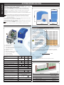 4
4
-
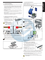 5
5
-
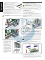 6
6
-
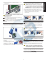 7
7
-
 8
8
-
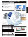 9
9
-
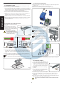 10
10
-
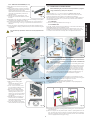 11
11
-
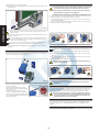 12
12
-
 13
13
-
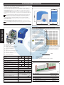 14
14
-
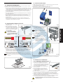 15
15
-
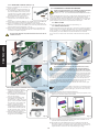 16
16
-
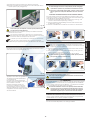 17
17
-
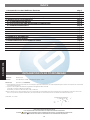 18
18
-
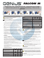 19
19
-
 20
20
-
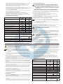 21
21
-
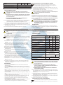 22
22
-
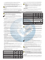 23
23
-
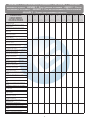 24
24
-
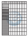 25
25
-
 26
26
-
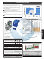 27
27
-
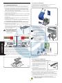 28
28
-
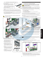 29
29
-
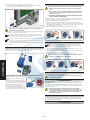 30
30
-
 31
31
-
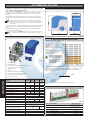 32
32
-
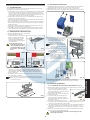 33
33
-
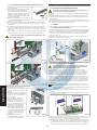 34
34
-
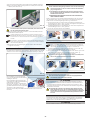 35
35
-
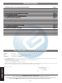 36
36
-
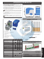 37
37
-
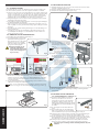 38
38
-
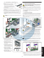 39
39
-
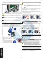 40
40
-
 41
41
-
 42
42
-
 43
43
-
 44
44


Genius FALCON M El manual del propietario
- Tipo
- El manual del propietario
en otros idiomas
- français: Genius FALCON M Le manuel du propriétaire
- italiano: Genius FALCON M Manuale del proprietario
- Deutsch: Genius FALCON M Bedienungsanleitung
- Nederlands: Genius FALCON M de handleiding
Artículos relacionados
-
Genius Falcon Manual de usuario
-
-
Genius FALCON 5M 8M 424M Instrucciones de operación
-
-
-
-
-
-
-