
CLPFLAT1TW
TUNABLE WHITE LED FLAT PAR
BLACK HOUSING WHITE HOUSING
CLPFLAT1TWIR CLPFLAT1TWIRWH
USER´S MANUAL
BEDIENUNGSANLEITUNG
MANUEL D`UTILISATION
MANUAL DE USUARIO
INSTRUKCJA OBSŁUGI
MANUALE D‘ USO

CONTENTS / INHALTSVERZEICHNIS / CONTENU / CONTENIDO / TREŚĆ / CONTENUTO
ENGLISH
PREVENTIVE MEASURES 3-4
INTRODUCTION 4
CONNECTIONS, OPERATING AND DISPLAY ELEMENTS 5-6
OPERATION 6-7
REMOTE CONTROL (OPTIONAL) 8
DMX TECHNOLOGY 9
TECHNICAL DATA 10
MANUFACTURER’S DECLARATIONS 10-11
DMX CONTROL 57-58
DEUTSCH
SICHERHEITSHINWEISE 12-13
EINFÜHRUNG 13
ANSCHLÜSSE, BEDIEN- UND ANZEIGEELEMENTE 14-15
BEDIENUNG 15-16
FERNBEDIENUNG (OPTIONAL) 17
DMX TECHNIK 18
TECHNISCHE DATEN 19
HERSTELLERERKLÄRUNGEN 19-20
DMX STEUERUNG 57-58
FRANCAIS
MESURES PRÉVENTIVES 21-22
INTRODUCTION 22
RACCORDEMENTS,
ÉLÉMENTS DE COMMANDE ET D’AFFICHAGE 23-24
MODE D’EMPLOI 24-25
COMMANDE À DISTANCE (EN OPTION) 26
TECHNOLOGIE DMX 27
FICHE TECHNIQUE 28
DÉCLARATIONS DU FABRICANT 29
PILOTAGE EN MODE DMX 57-58
ESPAÑOL
MEDIDAS DE SEGURIDAD 30-31
INTRODUCCIÓN 31-32
CONEXIONES, MANDOS Y ELEMENTOS DE VISUALIZACIÓN 32-33
FUNCIONAMIENTO 34
MANDO A DISTANCIA (OPCIONAL) 35
TECNOLOGÍA DMX 36
DATOS TÉCNICOS 37
DECLARACIONES DEL FABRICANTE 38
CONTROL DMX 57-58
POLSKI
ŚRODKI OSTROŻNOŚCI 39-40
WPROWADZENIE 40-41
PRZYŁĄCZA, ELEMENTY OBSŁUGOWE I WSKAŹNIKOWE 41-42
OBSŁUGA 42-43
PILOT ZDALNEGO STEROWANIA (OPCJONALNY) 44
TECHNIKA DMX 45
DANE TECHNICZNE 46
OŚWIADCZENIA PRODUCENTA 47
STEROWANIE DMX 57-58
ITALIANO
MISURE PRECAUZIONALI 48-49
INTRODUZIONE 49-50
CONNESSIONI, ELEMENTI DI COMANDO E VISUALIZZAZIONE 50-51
UTILIZZO 51-52
TELECOMANDO (OPZIONALE) 53
TECNOLOGIA DMX 54
DATI TECNICI 55
DICHIARAZIONI DEL PRODUTTORE 56
CONTROLLO DMX 57-58

ITALIANOPOLSKIESPAÑOL
FRANCAISDEUTSCHENGLISH
3
DMX
ENGLISH
YOU‘VE MADE THE RIGHT CHOICE!
We have designed this product to operate reliably over many years. Please read this User‘s Manual carefully, so that you can begin making
optimum use of your Cameo Light product quickly. Learn more about Cameo Light on our website WWW.CAMEOLIGHT.COM.
PREVENTIVE MEASURES
1. Please read these instructions carefully.
2. Keep all information and instructions in a safe place.
3. Follow the instructions.
4. Observe all safety warnings. Never remove safety warnings or other information from the equipment.
5. Use the equipment only in the intended manner and for the intended purpose.
6. Use only sufficiently stable and compatible stands and/or mounts (for fixed installations). Make certain that wall mounts are properly installed and
secured. Make certain that the equipment is installed securely and cannot fall down.
7. During installation, observ e the applicable safety regulations for your country.
8. Never install and operate the equipment near radiators, heat registers, ovens or other sources of heat. Make certain that the equipment is always
installed so that is cooled sufficiently and cannot overheat.
9. Never place sources of ignition, e.g., burning candles, on the equipment.
10. Ventilation slits must not be blocked.
11. Keep a minimum distance of 20 cm around and above the device.
12. Do not use this equipment in the immediate vicinity of water (does not apply to special outdoor equipment - in this case, observe the
special instructions noted below. Do not expose this equipment to flammable materials, fluids or gases. Avoid direct sunlight!
13. Make certain that dripping or splashed water cannot enter the equipment. Do not place containers filled with liquids, such as vases or
drinking vessels, on the equipment.
14. Make certain that objects cannot fall into the device.
15. Use this equipment only with the accessories recommended and intended by the manufacturer.
16. Do not open or modify this equipment.
17. After connecting the equipment, check all cables in order to prevent damage or accidents, e.g., due to tripping hazards.
18. During transport, make certain that the equipment cannot fall down and possibly cause property damage and personal injuries.
19. If your equipment is no longer functioning properly, if fluids or objects have gotten inside the equipment or if it has been damaged in anot
her way, switch it off immediately and unplug it from the mains outlet (if it is a powered device). This equipment may only be repaired by
authorized, qualified personnel.
20. Clean the equipment using a dry cloth.
21. Comply with all applicable disposal laws in your country. During disposal of packaging, please separate plastic and paper/cardboard.
22. Plastic bags must be kept out of reach of children.
23. Please note that changes or modifications not expressly approved by the party responsible for compliance could void the user´s authority
to operate the equipment.
FOR EQUIPMENT THAT CONNECTS TO THE POWER MAINS:
24. CAUTION: If the power cord of the device is equipped with an earthing contact, then it must be connected to an outlet with a protective
ground. Never deactivate the protective ground of a power cord.
25. If the equipment has been exposed to strong fluctuations in temperature (for example, after transport), do not switch it on immediately.
Moisture and condensation could damage the equipment. Do not switch on the equipment until it has reached room temperature.
26. Before connecting the equipment to the power outlet, first verify that the mains voltage and frequency match the values specified on the
equipment. If the equipment has a voltage selection switch, connect the equipment to the power outlet only if the equipment values and the
mains power values match. If the included power cord or power adapter does not fit in your wall outlet, contact your electrician.
27. Do not step on the power cord. Make certain that the power cable does not become kinked, especially at the mains outlet and/or power
adapter and the equipment connector.
28. When connecting the equipment, make certain that the power cord or power adapter is always freely accessible. Always disconnect the
equipment from the power supply if the equipment is not in use or if you want to clean the equipment. Always unplug the power cord and
power adapter from the power outlet at the plug or adapter and not by pulling on the cord. Never touch the power cord and power adapter
with wet hands.
29. Whenever possible, avoid switching the equipment on and off in quick succession because otherwise this can shorten the useful life of
the equipment.
30. IMPORTANT INFORMATION: Replace fuses only with fuses of the same type and rating. If a fuse blows repeatedly, please contact an
authorised service centre.
31. To disconnect the equipment from the power mains completely, unplug the power cord or power adapter from the power outlet.
32. If your device is equipped with a Volex power connector, the mating Volex equipment connector must be unlocked before it can be re-
moved. However, this also means that the equipment can slide and fall down if the power cable is pulled, which can lead to personal injuries
and/or other damage. For this reason, always be careful when laying cables.
33. Unplug the power cord and power adapter from the power outlet if there is a risk of a lightning strike or before extended periods of disuse.
34. The device must only be installed in a voltage-free condition (disconnect the mains plug from the mains).
35. Dust and other debris inside the unit may cause damage. The unit should be regularly serviced or cleaned (no guarantee) depending on
ambient conditions (dust etc., nicotine, fog) by qualified personnel to prevent overheating and malfunction.
36. Please keep a distance of at least 0.5 m to any combustible materials.
37. Power cables to power multiple devices must have a cross-section of at least 1.5 mm². Within the EU, the cables must correspond to
H05VV-F, or similar. Suitable cables are offered by Adam Hall. With these cables, you can connect multiple devices via the power OUT connection

4
DEUTSCHFRANCAIS
ESPAÑOL
ENGLISH
ITALIANO POLSKI
DMX
to the power IN connection of an additional device. Make sure that the total current consumption of all connected devices does not exceed the
specified value on all connected devices (label on the device). Make sure to keep power cable connections as short as possible.
CAUTION:
To reduce the risk of electric shock, do not remove cover (or back). There are no user serviceable parts
inside. Maintenance and repairs should be exclusively carried out by qualified service personnel.
The warning triangle with lightning symbol indicates dangerous uninsulated voltage inside the unit, which may cause an
electrical shock.
The warning triangle with exclamation mark indicates important operating and maintenance instructions.
Warning! This symbol indicates a hot surface. Certain parts of the housing can become hot during operation. After use, wait for
a cool-down period of at least 10 minutes before handling or transporting the device.
Warning! This device is designed for use below 2000 metres in altitude.
Warning! This product is not intended for use in tropical climates.
CAUTION! HIGH VOLUMES IN AUDIO PRODUCTS!
This device is meant for professional use. Therefore, commercial use of this equipment is subject to the respectively applicable national
accident prevention rules and regulations. As a manufacturer, Adam Hall is obligated to notify you formally about the existence of potential
health risks.
Hearing damage due to high volume and prolonged exposure: When in use, this product is capable of producing high sound-pressure levels
(SPL) that can lead to irreversible hearing damage in performers, employees, and audience members. For this reason, avoid prolonged
exposure to volumes in excess of 90 dB.
INTRODUCTION
TUNABLE WHITE LED FLAT PAR
CLPFLAT1TWIR (black casing)
CLPFLAT1TWIRWH (white casing)
CONTROL FUNCTIONS
1-channel, 2-channel, 3-channel and 7-channel DMX control
Optional infrared remote control
Master/slave modes
Standalone operation
FEATURES
7 bright 4 W cool white/warm white LEDs. 15 colour temperature presets. Brightness and stroboscope effect can be controlled from oper-
ating panel Master/slave functions. Rugged, flat casing. Noiseless due to convection cooling. Highly durable long-life LEDs. Double bracket.
Optional infrared remote control. Operating voltage 100–240 V AC. Power consumption 22 W
OPERATION
The Cameo FLAT1 TW IR is a DMX-512-controllable spotlight which can also be operated as a standalone unit and in master/slave mode. An
integrated IR sensor enables optional IR remote control.

ITALIANOPOLSKIESPAÑOL
FRANCAISDEUTSCHENGLISH
5
DMX
CONNECTIONS, OPERATING AND DISPLAY ELEMENTS
1
POWER IN/FUSE
IEC mains input socket with fuse holder. Operating voltage 100–240 V AC / 50–60 Hz. Connection using the IEC power cable supplied. Fuse
F3AL/250 V (5 x 20 mm). IMPORTANT: When replacing the fuse, only use a fuse of the same type and value. In the event of repeated fuse
failure, please contact an authorised service centre.
2
DMX IN
3-pin male XLR socket for connection to a DMX control device (e.g. DMX console).
3
DMX OUT
3-pin female XLR socket for sending the DMX control signal.
4
POWER OUT
IEC power output socket. Facilitates power supply to other CAMEO lights. Ensure that the total current consumption of all connected devices
does not exceed the value specified on the device in amperes (A).
21
3
4
5
6

6
DEUTSCHFRANCAIS
ESPAÑOL
ENGLISH
ITALIANO POLSKI
DMX
5
DISPLAY
The LED display shows the current operating mode and other system settings. The display disappears after 70 seconds of inactivity and is
re-activated as soon as one of the four keys MODE, ENTER, UP or DOWN is pressed.
6
OPERATING KEYS
MODE Select standalone functions, DMX mode and DMX address, slave mode and device settings.
ENTER Enter values and confirm changes.
Use the UP and DOWN keys to change brightness, stroboscope speed and DMX address.
OPERATION
NOTE
A few seconds after connecting the spotlight correctly to the mains it is ready for operation and the previously selected operating mode is activated.
INDIVIDUAL COLOUR TEMPERATURE
In order to set an individual colour temperature by mixing cold white and warm white and to create a preferred stroboscope effect, press
MODE repeatedly until “C” appears on the display and then press ENTER. Now use UP and DOWN to select “Cuxx” (cold white), “uuxx”
(warm white) or “CFxx” (stroboscope) and press ENTER to set the value, according to preference, between 00 and 99 using UP and DOWN
(CF00 = stroboscope deactivated, CF01 = slowest and CF99 = fastest stroboscope speed). Confirm your entry by pressing ENTER.
- / - / -
COLOUR TEMPERATURE PRESETS
In order to select one of the 15 colour temperature presets and set the brightness and stroboscope effect according to preference, press
MODE repeatedly until “Pr” appears on the display and then press ENTER. Now use UP and DOWN to select “Prxx” (Preset 1–15), confirm
by pressing ENTER and select a preset according to preference (preset 01 = cold white, preset 15 = warm white). Confirm by pressing
ENTER. Now use UP and DOWN once again to select “Pdxx” (dimmer) or “PFxx” (stroboscope) and press ENTER to set the value, according
to preference, between 00 and 99 using UP and DOWN (PF00 = stroboscope deactivated, PF01 = slowest and PF99 = fastest stroboscope
speed). Confirm your entry by pressing ENTER.
- / - / -
DIMMER RESPONSE
Use this menu item to set how the spotlight responds to changes in the DMX value in the dimmer channel. Press MODE repeatedly until
“drES” (Dimmer Response) is displayed and then press ENTER twice. Now set as desired using UP and DOWN. Confirm your entry by
pressing ENTER.
LEd = The spotlight responds abruptly to changes in the DMS value.
hALo = The spotlight responds like a halogen lamp, with gentle changes in brightness.
/

ITALIANOPOLSKIESPAÑOL
FRANCAISDEUTSCHENGLISH
7
DMX
DIMMER CURVE
Use this menu item to set how the brightness of the spotlight increases or decreases in relation to the DMX value in the dimmer channel.
Press MODE repeatedly until “dCUr” (Dimmer Curve) is displayed and then press ENTER twice. Now set as desired using UP and DOWN.
Confirm your entry by pressing ENTER.
dC1 = Linear – light intensity increases linearly with the DMX value.
dC2 = Exponential – light intensity can be finely adjusted at lower DMX values and broadly adjusted at higher DMX values.
dC3 = Logarithmic – light intensity can be broadly adjusted at lower DMX values and finely adjusted at higher DMX values.
dC4 = S-curve – light intensity can be finely adjusted at lower and higher DMX values and broadly adjusted at medium DMX values.
/ / /
linear
DMX value
Light intensity
exponential
DMX value
Light intensity
logarithmic
DMX value
Light intensity
S-curve
DMX value
Light intensity
CONFIGURE DMX START ADDRESS
Press MODE repeatedly until the current DMX start address setting is displayed (Axxx) and then press ENTER. Now set as desired using UP
and DOWN (hold down key to quickly change values). Confirm your entry by pressing ENTER.
-
DMX MODE SETTING
Press MODE repeatedly until the current DMX mode setting is displayed (xCh) and then press ENTER. Now set as desired using UP and DOWN.
Confirm your entry by pressing ENTER. DMX tables with the channel assignments can be found in these instructions under DMX CONTROL.
/ / /
SLAVE MODE
Press the MODE button repeatedly until "SLAV" appears on the display. Now connect the slave and the master units (same model) with
a DMX cable and enable one of the standalone modes on the master unit (individual colour temperature “C”, colour temperature presets
“Pr”). The slave unit will now follow the master unit.

8
DEUTSCHFRANCAIS
ESPAÑOL
ENGLISH
ITALIANO POLSKI
DMX
REMOTE CONTROL (OPTIONAL)
Aim the infrared remote control directly at the infrared sensor on the front of the lamp. The maximum range is approximately 8 metres. In
DMX and slave modes, the spotlight’s IR sensor is deactivated.
ON/OFF – BL (Blackout)
The blackout button is used to switch off all LEDs, regardless of operating mode enabled via the remote control. Press the blackout button
again to reactivate the previously selected mode.
(Brightness)
4-level brightness setting. The different brightness levels can be accessed by repeatedly pressing this key.
FL (Flash/Stroboscope)
4-level speed setting for the stroboscope effect (repeated pressing). Level 1 deactivates the stroboscope effect, Level 2 produces a slow
flash frequency, Level 3 a medium frequency and Level 4 the fastest frequency.
CW/WW
Use these two keys to mix an individual colour temperature (cold white/warm white). 10 brightness levels can be accessed by repeatedly
pressing the respective key, whereby the LEDs are switched off at Level 1.
Pr+/Pr-
15 different colour temperature presets can be accessed by repeatedly pressing the Pr+ and Pr- keys (cold white –> warm white).

ITALIANOPOLSKIESPAÑOL
FRANCAISDEUTSCHENGLISH
9
DMX
DMX TECHNOLOGY
DMX-512
DMX (Digital Multiplex) is the designation for a universal transmission protocol for
communications between corresponding devices and controllers. A DMX controller sends
DMX data to the connected DMX device(s). The DMX data is always transmitted as a serial
data stream that is forwarded from one connected device to the next via the "DMX IN" and
"DMX OUT" connectors (XLR plug-type connectors) that are found on every DMX-capable
device, provided the maximum number of devices does not exceed 32 units. The last device
in the chain needs to be equipped with a terminator (terminating resistor).
DMX CONNECTION
DMX is the common "language" via which a very wide range of types and models of equipment from various manufacturers can
be connected with one another and controlled via a central controller, provided that all of the devices and the controller are DMX
compatible. For optimum data transmission, it is necessary to keep the connecting cables between the individual devices as short as
possible. The order in which the devices are integrated in the DMX network has no influence on the addresses. Thus the device with
the DMX address 1 can be located at any position in the (serial) DMX chain: at the beginning, at the end or somewhere in the middle.
If the DMX address 1 is assigned to a device, the controller "knows" that it should send all data allocated to address 1 to this device
regardless of its position in the DMX network.
SERIAL CONNECTION OF MULTIPLE LIGHTS
1. Connect the male XLR connector (3-pin or 5-pin) of the DMX cable to the DMX output (female XLR socket) of the first DMX device
(e.g. DMX-Controller).
2. Connect the female 3-pin XLR connector of the DMX cable connected to the first projector to the DMX input (male 3-pin socket)
of the next DMX device. In the same way, connect the DMX output of this device to the DMX input of the next device and repeat until
all devices have been connected. Please note that as a rule, DMX devices are connected in series and connections cannot be shared
without active splitters. The maximum number of DMX devices in a DMX chain should not exceed 32 units.
The Adam Hall 3 STAR, 4 STAR, and 5 STAR product ranges include an extensive selection of suitable cables.
DMX CABLES
When fabricating your own cables, always observe the illustrations on this page. Never connect the shielding of the cable to the ground
contact of the plug, and always make certain that the shielding does not come into contact with the housing of the XLR plug. If the shielding
is connected to the ground, this can lead to short-circuiting and system malfunctions.
Pin Assignment
DMX cable with 3-pin XLR connectors: DMX cable with 5-pin XLR connectors (pin 4 and 5 are not used):
Shield
2
3
1
2
3
1
1
2
3
4
5
1
2
3
4
5
Shield
DMX TERMINATORS (TERMINATING RESISTORS)
To prevent system errors, the last device in a DMX chain needs to be equipped with a terminating resistor (120 ohm, 1/4 Watt).
3-pin XLR connector with a terminating resistor: K3DMXT3
5-pin XLR connector with a terminating resistor: K3DMXT5
Pin Assignment
3-pin XLR connector: 5-pin XLR connector:
2
3
1
1
2
3
4
5
DMX ADAPTER
The combination of DMX devices with 3-pin connectors and DMX devices with 5-pin connectors in a DMX chain is possible with suitable
adapters.
Pin Assignment
DMX Adapter 5-pin XLR male to 3-pin XLR female: K3DGF0020
Pins 4 and 5 are not used.
Pin Assignment
DMX Adapter 3-pin XLR male to 5-pin XLR female: K3DHM0020
Pins 4 and 5 are not used.

10
DEUTSCHFRANCAIS
ESPAÑOL
ENGLISH
ITALIANO POLSKI
DMX
TECHNICAL DATA
Model name: CLPFLAT1TWIR CLPFLAT1TWIRWH
Product Type: LED Par Can LED Par Can
Type: Flat Can Flat Can
Colour spectrum: Warm white/cold white (3400–7000 K) Warm white/cold white (3400–7000 K)
No. of LEDs: 7 7
LED type: 4 W Dual LED 4 W Dual LED
Refresh rate: 3000 Hz 3000 Hz
Beam angle: 25° 25°
DMX input: 3-pin male XLR 3-pin male XLR
DMX output: 3-pin female XLR 3-pin female XLR
DMX mode: 1-channel, 2-channel, 3-channel, 7-channel 1-channel, 2-channel, 3-channel, 7-channel
DMX functions: Master dimmer, 15 colour temperature presets,
cold white, warm white, stroboscope, 4 dimmer
curves, dimmer response
Master dimmer, 15 colour temperature presets,
cold white, warm white, stroboscope, 4 dimmer
curves, dimmer response
Standalone functions: 15 colour temperature presets, manual mixing
(CW/WW), stroboscope, master/slave mode
15 colour temperature presets, manual mixing
(CW/WW), stroboscope, master/slave mode
Control: USITT DMX512, IR remote control (optional) DMX512, IR remote control (optional)
Operating controls: Mode, Enter, Up, Down, IR remote control
(optional)
Mode, Enter, Up, Down, IR remote control
(optional)
Indicators: 4-digit LED display 4-digit LED display
Power supply connection: IEC input and output socket IEC input and output socket
Operating voltage: 100–240 V AC / 50–60 Hz. 100–240 V AC / 50–60 Hz.
Power consumption: 22 W 22 W
Fuse: F3AL/250 V (5 x 20 mm) F3AL/250 V (5 x 20 mm)
Ambient temperature (for
operation):
0–40°C 0–40°C
Relative air humidity: <85%, non-condensing <85%, non-condensing
Light intensity (@ 1 m): 6000 lx 6000 lx
Lighting power: 1220 lm 1220 lm
Housing material: ABS/metal ABS/metal
Housing colour: black white
Cooling: convection convection
Dimensions (W x H x D, without
bracket):
180 x 175 x 115 mm 180 x 175 x 115 mm
Weight: 1.2 kg 1.2 kg
Additional features: Double bracket included, IR remote control
optional
Double bracket included, IR remote control
optional
MANUFACTURER´S DECLARATIONS
MANUFACTURER‘S WARRANTY & LIMITATIONS OF LIABILITY
You can find our current warranty conditions and limitations of liability at: http://www.adamhall.com/media/shop/downloads/documents/
manufacturersdeclarations.pdf. To request warranty service for a product, please contact Adam Hall GmbH, Daimler Straße 9,
61267 Neu Anspach / Email: [email protected] / +49 (0)6081 / 9419-0.
CORRECT DISPOSAL OF THIS PRODUCT
(valid in the European Union and other European countries with a differentiated waste collection system)
This symbol on the product, or on its documents indicates that the device may not be treated as household waste. This is to avoid
environmental damage or personal injury due to uncontrolled waste disposal. Please dispose of this product separately from other waste
and have it recycled to promote sustainable economic activity. Household users should contact either the retailer where they purchased
this product, or their local government office, for details on where and how they can recycle this item in an environmentally friendly manner.
Business users should contact their supplier and check the terms and conditions of the purchase contract. This product should not be mixed
with other commercial waste for disposal.

ITALIANOPOLSKIESPAÑOL
FRANCAISDEUTSCHENGLISH
11
DMX
CE Compliance
Adam Hall GmbH states that this product meets the following guidelines (where applicable):
R&TTE (1999/5/EC) or RED (2014/53/EU) from June 2017
Low voltage directive (2014/35/EU)
EMV directive (2014/30/EU)
RoHS (2011/65/EU)
The complete declaration of conformity can be found at www.adamhall.com.
Furthermore, you may also direct your enquiry to [email protected].

12
DEUTSCHFRANCAIS
ESPAÑOL
ENGLISH
ITALIANO POLSKI
DMX
DEUTSCH
SIE HABEN DIE RICHTIGE WAHL GETROFFEN!
Dieses Gerät wurde unter hohen Qualitätsanforderungen entwickelt und gefertigt, um viele Jahre einen reibungslosen Betrieb zu gewähr-
leisten. Bitte lesen Sie diese Bedienungsanleitung sorgfältig, damit Sie Ihr neues Produkt von Cameo Light schnell und optimal einsetzen
können. Weitere Informationen über Cameo Light erhalten Sie auf unserer Website WWW.CAMEOLIGHT.COM.
SICHERHEITSHINWEISE
1. Lesen Sie diese Anleitung bitte sorgfältig durch.
2. Bewahren Sie alle Informationen und Anleitungen an einem sicheren Ort auf.
3. Befolgen Sie die Anweisungen.
4. Beachten Sie alle Warnhinweise. Entfernen Sie keine Sicherheitshinweise oder andere Informationen vom Gerät.
5. Verwenden Sie das Gerät nur in der vorgesehenen Art und Weise.
6. Verwenden Sie ausschließlich stabile und passende Stative bzw. Befestigungen (bei Festinstallationen). Stellen Sie sicher, dass Wandhalterungen
ordnungsgemäß installiert und gesichert sind. Stellen Sie sicher, dass das Gerät sicher installiert ist und nicht herunterfallen kann.
7. Beachten Sie bei der Installation die für Ihr Land geltenden Sicherheitsvorschriften.
8. Installieren und betreiben Sie das Gerät nicht in der Nähe von Heizkörpern, Wärmespeichern, Öfen oder sonstigen Wärmequellen. Sorgen
Sie dafür, dass das Gerät immer so installiert ist, dass es ausreichend gekühlt wird und nicht überhitzen kann.
9. Platzieren Sie keine Zündquellen wie z.B. brennende Kerzen auf dem Gerät.
10. Lüftungsschlitze dürfen nicht blockiert werden.
11. Halten Sie einen Mindestabstand von 20 cm seitlich und oberhalb des Geräts ein.
12. Betreiben Sie das Gerät nicht in unmittelbarer Nähe von Wasser. Bringen Sie das Gerät nicht mit brennbaren Materialien, Flüssigkeiten
oder Gasen in Berührung. Direkte Sonneneinstrahlung vermeiden!
13. Sorgen Sie dafür, dass kein Tropf- oder Spritzwasser in das Gerät eindringen kann. Stellen Sie keine mit Flüssigkeit gefüllten Behältnisse
wie Vasen oder Trinkgefäße auf das Gerät.
14. Sorgen Sie dafür, dass keine Gegenstände in das Gerät fallen können.
15. Betreiben Sie das Gerät nur mit dem vom Hersteller empfohlenen und vorgesehenen Zubehör.
16. Öffnen Sie das Gerät nicht und verändern Sie es nicht.
17. Überprüfen Sie nach dem Anschluss des Geräts alle Kabelwege, um Schäden oder Unfälle, z. B. durch Stolperfallen zu vermeiden.
18. Achten Sie beim Transport darauf, dass das Gerät nicht herunterfallen und dabei möglicherweise Sach- und Personenschäden verursachen kann.
19. Wenn Ihr Gerät nicht mehr ordnungsgemäß funktioniert, Flüssigkeiten oder Gegenstände in das Geräteinnere gelangt sind, oder das
Gerät anderweitig beschädigt wurde, schalten Sie es sofort aus und trennen es von der Netzsteckdose (sofern es sich um ein aktives Gerät
handelt). Dieses Gerät darf nur von autorisiertem Fachpersonal repariert werden.
20. Verwenden Sie zur Reinigung des Geräts ein trockenes Tuch.
21. Beachten Sie alle in Ihrem Land geltenden Entsorgungsgesetze. Trennen Sie bei der Entsorgung der Verpackung bitte Kunststoff und
Papier bzw. Kartonagen voneinander.
22. Kunststoffbeutel müssen außer Reichweite von Kindern aufbewahrt werden.
23. Sämtliche vom Benutzer vorgenommenen Änderungen und Modifikationen, denen die für die Einhaltung der Richtlinien verantwortliche
Partei nicht ausdrücklich zugestimmt hat, können zum Entzug der Betriebserlaubnis für das Gerät führen.
BEI GERÄTEN MIT NETZANSCHLUSS:
24. ACHTUNG: Wenn das Netzkabel des Geräts mit einem Schutzkontakt ausgestattet ist, muss es an einer Steckdose mit Schutzleiter
angeschlossen werden. Deaktivieren Sie niemals den Schutzleiter eines Netzkabels.
25. Schalten Sie das Gerät nicht sofort ein, wenn es starken Temperaturschwankungen ausgesetzt war (beispielsweise nach dem Transport).
Feuchtigkeit und Kondensat könnten das Gerät beschädigen. Schalten Sie das Gerät erst ein, wenn es Zimmertemperatur erreicht hat.
26. Bevor Sie das Gerät an die Steckdose anschließen, prüfen Sie zuerst, ob die Spannung und die Frequenz des Stromnetzes mit den auf
dem Gerät angegebenen Werten übereinstimmen. Verfügt das Gerät über einen Spannungswahlschalter, schließen Sie das Gerät nur an die
Steckdose an, wenn die Gerätewerte mit den Werten des Stromnetzes übereinstimmen. Wenn das mitgelieferte Netzkabel bzw. der mitgelie-
ferte Netzadapter nicht in Ihre Netzsteckdose passt, wenden Sie sich an Ihren Elektriker.
27. Treten Sie nicht auf das Netzkabel. Sorgen Sie dafür, dass spannungsführende Kabel speziell an der Netzbuchse bzw. am Netzadapter
und der Gerätebuchse nicht geknickt werden.
28. Achten Sie bei der Verkabelung des Geräts immer darauf, dass das Netzkabel bzw. der Netzadapter stets frei zugänglich ist. Trennen Sie
das Gerät stets von der Stromzuführung, wenn das Gerät nicht benutzt wird, oder Sie das Gerät reinigen möchten. Ziehen Sie Netzkabel und
Netzadapter immer am Stecker bzw. am Adapter und nicht am Kabel aus der Steckdose. Berühren Sie Netzkabel und Netzadapter niemals
mit nassen Händen.
29. Schalten Sie das Gerät möglichst nicht schnell hintereinander ein und aus, da sonst die Lebensdauer des Geräts beeinträchtigt werden könnte.
30. WICHTIGER HINWEIS: Ersetzen Sie Sicherungen ausschließlich durch Sicherungen des gleichen Typs und Wertes. Sollte eine Sicherung
wiederholt auslösen, wenden Sie sich bitte an ein autorisiertes Servicezentrum.
31. Um das Gerät vollständig vom Stromnetz zu trennen, entfernen Sie das Netzkabel bzw. den Netzadapter aus der Steckdose.
32. Wenn Ihr Gerät mit einem Volex-Netzanschluss bestückt ist, muss der passende Volex-Gerätestecker entsperrt werden, bevor er entfernt
werden kann. Das bedeutet aber auch, dass das Gerät durch ein Ziehen am Netzkabel verrutschen und herunterfallen kann, wodurch Perso-
nen verletzt werden und/oder andere Schäden auftreten können. Verlegen Sie Ihre Kabel daher immer sorgfältig.
33. Entfernen Sie Netzkabel und Netzadapter aus der Steckdose bei Gefahr eines Blitzschlags oder wenn Sie das Gerät länger nicht verwenden.
34. Das Gerät darf nur im spannungsfreien Zustand (Trennung des Netzsteckers vom Stromnetz) installiert werden.
35. Staub und andere Ablagerungen im Inneren des Geräts können es beschädigen. Das Gerät sollte je nach Umgebungsbedingungen
(Staub, Nikotin, Nebel etc.) regelmäßig von qualifiziertem Fachpersonal gewartet bzw. gesäubert werden (keine Garantieleistung),
um Überhitzung und Fehlfunktionen zu vermeiden.

ITALIANOPOLSKIESPAÑOL
FRANCAISDEUTSCHENGLISH
13
DMX
36. Der Abstand zu brennbaren Materialien muss mindestens 0,5 m betragen.
37. Netzleitungen zur Spannungsversorgung mehrerer Geräte müssen mindestens 1,5 mm² Aderquerschnitt aufweisen. In der EU müssen
die Leitungen H05VV-F, oder gleichartig, entsprechen. Geeignete Leitungen werden von Adam Hall angeboten. Mit diesen Leitungen können
Sie mehrere Geräte über den Power out Anschluss mit dem Power IN Anschluss eines weiteren Gerätes verbinden. Beachten Sie, dass die
gesamte Stromaufnahme aller angeschlossenen Geräte den vorgegebenen Wert nicht überschreitet (Aufdruck auf dem Gerät). Achten Sie
darauf, Netzleitungen so kurz wie möglich zu halten.
ACHTUNG
Entfernen Sie niemals die Abdeckung, da sonst das Risiko eines elektrischen Schlages besteht. Im
Inneren des Geräts befinden sich keine Teile, die vom Bediener repariert oder gewartet werden können.
Lassen Sie Wartung und Reparaturen ausschließlich von qualifiziertem Servicepersonal durchführen.
Das gleichseitige Dreieck mit Blitzsymbol warnt vor nichtisolierten, gefährlichen Spannungen im Geräteinneren, die einen
elektrischen Schlag verursachen können.
Das gleichseitige Dreieck mit Ausrufungszeichen kennzeichnet wichtige Bedienungs- und Wartungshinweise.
Warnung! Dieses Symbol kennzeichnet heiße Oberflächen. Während des Betriebs können bestimmte Teile des Gehäuses heiß
werden. Berühren oder transportieren Sie das Gerät nach einem Einsatz erst nach einer Abkühlzeit von mindestens 10 Minuten.
Warnung! Dieses Gerät ist für eine Nutzung bis zu einer Höhe von maximal 2000 Metern über dem Meeresspiegel bestimmt.
Warnung! Dieses Gerät ist nicht für den Einsatz in tropischen Klimazonen bestimmt.
VORSICHT! WICHTIGE HINWEISE IN BEZUG AUF LICHT-PRODUKTE!
1. Das Produkt ist für den professionellen Einsatz im Bereich der Veranstaltungstechnik entwickelt worden und ist nicht für die Raumbeleuchtung in
Haushalten geeignet.
2. Blicken Sie niemals, auch nicht kurzzeitig, direkt in den Lichtstrahl.
3. Blicken Sie niemals mit optischen Geräten wie Vergrößerungsgläsern in den Lichtstrahl.
4. Stroboskopeffekte können unter Umständen bei empfindlichen Menschen epileptische Anfälle auslösen! Epilepsiekranke Menschen
sollten daher unbedingt Orte meiden, an denen Stroboskope eingesetzt werden.
EINFÜHRUNG
TUNABLE WHITE LED FLAT PAR
CLPFLAT1TWIR (schwarzes Gehäuse)
CLPFLAT1TWIRWH (weißes Gehäuse)
STEUERUNGSFUNKTIONEN
1-Kanal, 2-Kanal, 3-Kanal und 7-Kanal DMX-Steuerung
Steuerung über optionale Infrarot-Fernbedienung
Master/Slave-Betrieb
Standalone Funktion
EIGENSCHAFTEN
7 leuchtstarke 4W Kaltweiß / Warmweiß LEDs. 15 Farbtemperatur-Presets. Helligkeit und Stroboskopeffekt über Bedienpanel steuerbar.
Master/Slave-Funktionalität. Robustes, flaches Gehäuse. Geräuschlos durch Konvektionskühlung. Longlife-LEDs mit besonders langer
Lebensdauer. Doppelbügel. Steuerung über Infrarot-Fernbedienung (optional). Betriebsspannung 100V-240V AC. Leistungsaufnahme 22W
BEDIENUNG
Der Cameo FLAT1 TW IR ist ein DMX-512-steuerbarer Scheinwerfer und lässt sich ebenso als Standalone-Gerät und im Master/Slave-Modus
betreiben. Der integrierte IR-Sensor ermöglicht die Steuerung über eine optionale IR-Fernbedienung.

14
DEUTSCHFRANCAIS
ESPAÑOL
ENGLISH
ITALIANO POLSKI
DMX
ANSCHLÜSSE, BEDIEN- UND ANZEIGEELEMENTE
1
POWER IN/FUSE
IEC-Netzeingangsbuchse mit Sicherungshalter. Betriebsspannung 100 - 240V AC / 50 - 60Hz. Anschluss über das mitgelieferte IEC-Netzkabel.
Sicherung F3AL / 250V (5 x 20 mm). WICHTIGER HINWEIS: Ersetzen Sie die Sicherung ausschließlich durch eine Sicherung des gleichen Typs
und mit gleichen Werten. Sollte die Sicherung wiederholt auslösen, wenden Sie sich bitte an ein autorisiertes Servicezentrum.
2
DMX IN
3-polige männliche XLR-Buchse zum Anschließen eines DMX-Kontrollgerätes (z.B. DMX-Pult).
3
DMX OUT
3-polige weibliche XLR-Buchse zum Weiterleiten des DMX-Steuersignals.
4
POWER OUT
IEC Netzausgangsbuchse. Dient der Netzversorgung weiterer CAMEO Scheinwerfer. Achten Sie darauf, dass die gesamte Stromaufnahme
aller angeschlossenen Geräte den auf dem Gerät in Ampere (A) angegebenen Wert nicht überschreitet.
21
3
4
5
6

ITALIANOPOLSKIESPAÑOL
FRANCAISDEUTSCHENGLISH
15
DMX
BEDIENUNG
HINWEIS
Wenige Sekunden nachdem der Scheinwerfer korrekt am Stromnetz angeschlossen wird, ist er betriebsbereit und die Betriebsart, die zuvor
angewählt war, wird aktiviert.
INDIVIDUELLE FARBTEMPERATUR
Um eine individuelle Farbtemperatur durch Mischen von Kaltweiß und Warmweiß und den Stroboskop-Effekt nach Wunsch einzustellen, drü-
cken Sie so oft auf MODE, bis „C„ im Display angezeigt wird und drücken auf ENTER. Mit UP und DOWN wählen Sie nun „Cuxx“ (Kaltweiß),
„uuxx“ (Warmweiß) oder „CFxx“ (Stroboskop) aus und drücken auf ENTER, um den entsprechenden Wert nach Wunsch von 00 bis 99 mit
Hilfe von UP und DOWN einzustellen (CF00 = Stroboskop deaktiviert, CF01 = langsamste und CF99 = schnellste Stroboskopgeschwindig-
keit). Bestätigen Sie die Eingabe mit ENTER.
- / - / -
FARBTEMPERATUR-PRESETS
Um eines der 15 Farbtemperatur-Presets, die Helligkeit und den Stroboskop-Effekt nach Wunsch einzustellen, drücken Sie so oft auf MODE,
bis „Pr „ im Display angezeigt wird und drücken dann auf ENTER. Mit UP und DOWN wählen Sie nun „Prxx“ (Preset 1 - 15) aus, bestätigen
mit ENTER und wählen ein Preset nach Wunsch aus (Preset 01 = Kaltweiß, Preset 15 = Warmweiß). Bestätigen Sie mit ENTER. Wählen
Sie nun wiederum mit UP und DOWN „Pdxx“ (Dimmer) oder „PFxx“ (Stroboskop) aus und drücken auf ENTER, um den entsprechenden
Wert nach Wunsch von 00 bis 99 mit Hilfe von UP und DOWN einzustellen (PF00 = Stroboskop deaktiviert, PF01 = langsamste und PF99 =
schnellste Stroboskopgeschwindigkeit). Bestätigen Sie die Eingabe mit ENTER.
- / - / -
DIMMER-REAKTION
In diesem Menüpunkt kann eingestellt werden, wie der Strahler auf Änderungen des DMX-Werts im Dimmer-Kanal reagiert. Drücken Sie so
oft auf MODE, bis „drES“ (Dimmer Response) angezeigt wird und drücken 2x auf ENTER um nun die Einstellung mit Hilfe von UP und DOWN
nach Wunsch durchzuführen. Bestätigen Sie die Eingabe mit ENTER.
LEd = Der Strahler reagiert abrupt auf Änderungen des DMX-Werts.
hALo = Der Strahler verhält sich ähnlich einem Halogenstrahler mit sanften Helligkeitsänderungen.
/
5
DISPLAY
Das LED-Display zeigt den aktuellen Betriebsmodus und weitere Systemeinstellungen an. Nach ca. 70 Sekunden Inaktivität erlischt das
Display und wird wieder aktiviert, sobald einer der 4 Bedientaster MODE, ENTER, UP und DOWN betätigt wird.
6
BEDIENTASTEN
MODE Auswählen der Standalone-Funktionen, DMX-Betriebsart und DMX-Adresse, Slave-Betrieb, sowie Geräte-Einstellungen.
ENTER Ermöglicht einen Wert zu ändern und Wertänderungen zu bestätigen.
Nutzen Sie die UP und DOWN Tasten, um z.B. Helligkeit, Stroboskopgeschwindigkeit, oder DMX-Adresse zu ändern.

16
DEUTSCHFRANCAIS
ESPAÑOL
ENGLISH
ITALIANO POLSKI
DMX
DIMMERKURVE
In diesem Menüpunkt kann eingestellt werden, wie die Helligkeit des Strahlers im Verhältnis zum DMX-Wert im Dimmer-Kanal zu- oder
abnimmt. Drücken Sie so oft auf MODE, bis „dCUr“ (Dimmer Curve) angezeigt wird und drücken 2x auf ENTER um nun die Einstellung mit Hilfe
von UP und DOWN nach Wunsch durchzuführen. Bestätigen Sie die Eingabe mit ENTER.
dC1 = Linear, die Lichtintensität verläuft linear mit dem DMX-Wert.
dC2 = Exponentiell, die Lichtintensität lässt sich im unteren DMX-Wertbereich fein und im oberen DMX-Wertbereich grob einstellen.
dC3 = Logarithmisch, die Lichtintensität lässt sich im unteren DMX-Wertbereich grob und im oberen DMX-Wertbereich fein einstellen.
dC4 = S-Kurve, die Lichtintensität lässt sich im unteren und oberen DMX-Wertbereich fein und im mittleren DMX-Wertbereich grob einstellen.
/ / /
linear
DMX-Wert
Lichtintensität
exponentiell
DMX-Wert
Lichtintensität
logarithmisch
DMX-Wert
Lichtintensität
S-Kurve
DMX-Wert
Lichtintensität
DMX-STARTADRESSE EINSTELLEN
Drücken Sie so oft auf MODE, bis die aktuell eingestellte DMX-Startadresse angezeigt wird (Axxx) und drücken auf ENTER, um nun die
Einstellung mit Hilfe von UP und DOWN nach Wunsch durchzuführen (lang drücken für schnelle Wertänderung). Bestätigen Sie die Eingabe
mit ENTER.
-
DMX-BETRIEBSART EINSTELLEN
Drücken Sie so oft auf MODE, bis die aktuell eingestellte DMX-Betriebsart angezeigt wird (xCh) und drücken auf ENTER, um nun die Einstel-
lung mit Hilfe von UP und DOWN nach Wunsch durchzuführen. Bestätigen Sie die Eingabe mit ENTER. DMX-Tabellen mit den Kanalbelegun-
gen finden Sie in dieser Anleitung unter DMX STEUERUNG.
/ / /
SLAVE-BETRIEB
Drücken Sie so oft auf MODE, bis im Display „SLAV“ angezeigt wird. Verbinden Sie nun die Slave- und die Master-Einheit (gleiches Modell)
mit Hilfe eines DMX-Kabels und aktivieren in der Master-Einheit eine der Standalone Betriebsarten (Individuelle Farbtemperatur „C“,
Farbtemperatur-Presets „Pr“). Nun folgt die Slave-Einheit der Master-Einheit.

ITALIANOPOLSKIESPAÑOL
FRANCAISDEUTSCHENGLISH
17
DMX
FERNBEDIENUNG (OPTIONAL)
Richten Sie die Infrarot-Fernbedienung in Sichtverbindung direkt auf den auf der Vorderseite des Strahlers verbauten Infrarot-Sensor. Die
maximale Reichweite beträgt circa 8 Meter. In der DMX- und der Slave-Betriebsart ist der Sensor des Strahlers deaktiviert.
ON/OFF - BL (Blackout)
Die Blackout-Taste dient dazu, alle LEDs abzuschalten, unabhängig davon, welche von der Fernbedienung kontrollierten Betriebsart aktiviert
ist. Bei nochmaligem Drücken der Blackout-Taste wird die zuvor ausgewählte Betriebsart wieder aktiviert.
(Brightness)
4-stufige Helligkeitseinstellung. Die unterschiedlichen Helligkeitsabstufungen können durch mehrmaliges Drücken dieser Taste abgerufen werden.
FL (Flash / Stroboskop)
4-stufige Geschwindigkeitseinstellung für den Stroboskop-Effekt (mehrmaliges Drücken). Stufe 1 deaktiviert den Stroboskop-Effekt, Stufe 2
erzeugt eine langsame, Stufe 3 eine mittlere und Stufe 4 die schnellste Blitzfrequenz.
CW / WW
Nutzen Sie diese 2 Taster, um eine individuelle Farbtemperatur zu mischen (Kaltweiß / Warmweiß). 10 Helligkeitsstufen können durch
mehrmaliges Drücken des entsprechenden Tasters abgerufen werden, wobei bei Stufe 1 die LEDs abgeschaltet sind.
Pr+ / Pr-
15 verschiedene Farbtemperatur-Presets können mit Hilfe der Taster Pr+ und Pr- durch wiederholtes Drücken abgerufen werden
(Kaltweiß -> Warmweiß).

18
DEUTSCHFRANCAIS
ESPAÑOL
ENGLISH
ITALIANO POLSKI
DMX
DMX TECHNIK
DMX-512
DMX (Digital Multiplex) ist die Bezeichnung für ein universelles Übertragungsprotokoll für
die Kommunikation zwischen entsprechenden Geräten und Controllern. Ein DMX-Controller
sendet DMX-Daten an das/die angeschlossene(n) DMX-Gerät(e). Die DMX-Datenübertragung
erfolgt stets als serieller Datenstrom, der über die an jedem DMX-fähigen Gerät vorhandenen
DMX IN- und DMX OUT-Anschlüsse (XLR-Steckverbinder) von einem angeschlossenen
Gerät an das nächste weitergeleitet wird, wobei die maximale Anzahl der Geräte 32 nicht
überschreiten darf. Das letzte Gerät der Kette ist mit einem Abschlussstecker (Terminator) zu
bestücken.
DMX-VERBINDUNG:
DMX ist die gemeinsame "Sprache", über die sich die unterschiedlichsten Gerätetypen und Modelle verschiedener Hersteller
miteinander verkoppeln und über einen zentralen Controller steuern lassen, sofern sämtliche Geräte und der Controller DMX-
kompatibel sind. Für eine optimale Datenübertragung ist es erforderlich, die Verbindungskabel zwischen den einzelnen Geräten so
kurz wie möglich zu halten. Die Reihenfolge, in der die Geräte in das DMX-Netzwerk eingebunden sind, hat keinen Einfluss auf die
Adressierung. So kann sich das Gerät mit der DMX-Adresse 1 an einer beliebigen Position in der (seriellen) DMX-Kette befinden, am
Anfang, am Ende oder irgendwo in der Mitte. Wird einem Gerät die DMX-Adresse 1 zugewiesen, "weiß" der Controller, dass er alle
der Adresse 1 zugeordneten Daten an dieses Gerät senden soll, ungeachtet seiner Position im DMX-Verbund.
SERIELLE VERKOPPLUNG MEHRERER SCHEINWERFER
1. Verbinden Sie den männlichen XLR-Stecker (3-Pol oder 5-Pol) des DMX-Kabels mit dem DMX-Ausgang (weibliche XLR-Buchse)
des ersten DMX-Geräts (z.B. DMX-Controller).
2. Verbinden Sie den weibliche XLR-Stecker des an den ersten Scheinwerfer angeschlossenen DMX-Kabels mit dem DMX-Eingang
(männliche XLR-Buchse) des nächsten DMX-Geräts. Verbinden Sie den DMX-Ausgang dieses Geräts in der gleichen Weise mit dem
DMX-Eingang des nächsten Geräts und so weiter. Bitte beachten Sie, dass DMX-Geräte grundsätzlich seriell verschaltet werden und
die Verbindungen nicht ohne aktiven Splitter geteilt werden können. Die maximale Anzahl der DMX-Geräte einer DMX-Kette darf 32
nicht überschreiten.
Eine umfangreiche Auswahl geeigneter DMX-Kabel finden Sie in den Adam Hall Produktlinien 3 STAR, 4 STAR und 5 STAR.
DMX-KABEL:
Beachten Sie bei der Anfertigung eigener Kabel unbedingt die Abbildungen auf dieser Seite. Verbinden Sie auf keinen Fall die Abschirmung
des Kabels mit dem Massekontakt des Steckers, und achten Sie darauf, dass die Abschirmung nicht mit dem XLR-Steckergehäuse in
Kontakt kommt. Hat die Abschirmung Massekontakt, kann dies zu Systemfehlern führen.
Steckerbelegung:
DMX-Kabel mit 3-Pol XLR-Steckern: DMX-Kabel mit 5-Pol XLR-Steckern (Pin 4 und 5 sind nicht belegt.):
Shield
2
3
1
2
3
1
1
2
3
4
5
1
2
3
4
5
Shield
DMX-ABSCHLUSSSTECKER (TERMINATOR):
Um Systemfehler zu vermeiden, ist das letzte Gerät einer DMX-Kette mit einem Abschlusswiderstand zu bestücken (120 Ohm, 1/4 Watt).
3-Pol XLR-Stecker mit Abschlusswiderstand: K3DMXT3
5-Pol XLR-Stecker mit Abschlusswiderstand: K3DMXT5
Steckerbelegung:
3-Pol XLR-Stecker: 5-Pol XLR-Stecker:
2
3
1
1
2
3
4
5
DMX-ADAPTER:
Die Kombination von DMX-Geräten mit 3-Pol Anschlüssen und DMX-Geräten mit 5-Pol Anschlüssen in einer DMX-Kette ist mit Hilfe von
Adaptern ebenso möglich.
Steckerbelegung
DMX-Adapter 5-Pol XLR male auf 3-Pol XLR female: K3DGF0020
Pin 4 und 5 sind nicht belegt.
Steckerbelegung
DMX-Adapter 3-Pol XLR male auf 5-Pol XLR female: K3DHM0020
Pin 4 und 5 sind nicht belegt.

ITALIANOPOLSKIESPAÑOL
FRANCAISDEUTSCHENGLISH
19
DMX
TECHNISCHE DATEN
Modellbezeichnung: CLPFLAT1TWIR CLPFLAT1TWIRWH
Produktart: LED Par Can LED Par Can
Typ: Flat Can Flat Can
Farbspektrum: Warmweiß/Kaltweiß (3400K - 7000K) Warmweiß/Kaltweiß (3400K - 7000K)
LED Anzahl: 7 7
LED Typ: 4W Dual LED 4W Dual LED
Wiederholrate: 3000 Hz 3000 Hz
Abstrahlwinkel: 25° 25°
DMX-Eingang: 3-Pol XLR männlich 3-Pol XLR männlich
DMX-Ausgang: 3-Pol XLR weiblich 3-Pol XLR weiblich
DMX-Modus: 1-Kanal, 2-Kanal, 3-Kanal, 7-Kanal 1-Kanal, 2-Kanal, 3-Kanal, 7-Kanal
DMX Funktionen: Master Dimmer, 15 Farbtemperatur-Presets,
Kaltweiß, Warmweiß, Stroboskop, 4 Dimmerkur-
ven, Dimmer Reaktion
Master Dimmer, 15 Farbtemperatur-Presets,
Kaltweiß, Warmweiß, Stroboskop, 4 Dimmerkur-
ven, Dimmer Reaktion
Standalone Funktionen: 15 Farbtemperatur-Presets, manuelles Mischen
(CW/WW), Stroboskop, Master/Slave-Betrieb
15 Farbtemperatur-Presets, manuelles Mischen
(CW/WW), Stroboskop, Master/Slave-Betrieb
Steuerung: USITT DMX512, IR-Fernbedienung (optional) DMX512, IR-Fernbedienung (optional)
Bedienelemente: Mode, Enter, Up, Down, IR-Fernbedienung
(optional)
Mode, Enter, Up, Down, IR-Fernbedienung
(optional)
Anzeigeelemente: 4-stelliges LED-Display 4-stelliges LED-Display
Stromversorgungsanschluss: IEC-Buchse Ein- und Ausgang IEC-Buchse Ein- und Ausgang
Betriebsspannung: 100 - 240 V AC / 50 - 60 Hz 100 - 240 V AC / 50 - 60 Hz
Leistungsaufnahme: 22 W 22 W
Sicherung: F3AL / 250V (5 x 20mm) F3AL / 250V (5 x 20mm)
Umgebungstemperatur (in Betrieb): 0°C - 40°C 0°C - 40°C
Relative Luftfeuchtigkeit: <85%, nicht kondensierend <85%, nicht kondensierend
Beleuchtungsstärke (@ 1m): 6000 lx 6000 lx
Lichtstrom: 1220 lm 1220 lm
Gehäusematerial: ABS, Metall ABS, Metall
Gehäusefarbe: schwarz weiß
Kühlung: Konvektion Konvektion
Abmessungen (B x H x T, ohne
Bügel):
180 x 175 x 115 mm 180 x 175 x 115 mm
Gewicht: 1,2 kg 1,2 kg
Weitere Eigenschaften: Doppelbügel inklusive, IR-Fernbedienung
optional
Doppelbügel inklusive, IR-Fernbedienung
optional
HERSTELLERERKLÄRUNGEN
HERSTELLERGARANTIE & HAFTUNGSBESCHRÄNKUNG
Unsere aktuellen Garantiebedingungen und Haftungsbeschränkung finden Sie unter: http://www.adamhall.com/media/shop/downloads/
documents/manufacturersdeclarations.pdf. Im Service Fall wenden Sie sich bitte an Adam Hall GmbH, Daimlerstraße 9, 61267 Neu Anspach
/ E-Mail [email protected] / +49 (0)6081 / 9419-0.
KORREKTE ENTSORGUNG DIESES PRODUKTS
(Gültig in der Europäischen Union und anderen europäischen Ländern mit Mülltrennung) Dieses Symbol auf dem Produkt oder
dazugehörigen Dokumenten weist darauf hin, dass das Gerät am Ende der Produktlebenszeit nicht zusammen mit dem normalen
Hausmüll entsorgt werden darf, um Umwelt- oder Personenschäden durch unkontrollierte Abfallentsorgung zu vermeiden. Bitte entsorgen
Sie dieses Produkt getrennt von anderen Abfällen und führen es zur Förderung nachhaltiger Wirtschaftskreisläufe dem Recycling zu. Als Pri-
vatkunde erhalten Sie Informationen zu umweltfreundlichen Entsorgungsmöglichkeiten über den Händler, bei dem das Produkt erwor¬ben
wurde, oder über die entsprechenden regionalen Behörden. Als gewerblicher Nutzer kontaktieren Sie bitte Ihren Lieferanten und prüfen
die ggf. vertraglich vereinbarten Konditionen zur Entsorgung der Geräte. Dieses Produkt darf nicht zusammen mit anderen gewerblichen
Abfällen entsorgt werden.

20
DEUTSCHFRANCAIS
ESPAÑOL
ENGLISH
ITALIANO POLSKI
DMX
CE-Konformität
Hiermit erklärt die Adam Hall GmbH, dass dieses Produkt folgenden Richtlinien entspricht (soweit zutreffend):
R&TTE (1999/5/EG) bzw. RED (2014/53/EU) ab Juni 2017
Niederspannungsrichtlinie (2014/35/EU)
EMV-Richtlinie (2014/30/EU)
RoHS (2011/65/EU)
Die vollständige Konformitätserklärung finden Sie unter www.adamhall.com.
Des Weiteren können Sie diese auch unter [email protected] anfragen.

ITALIANOPOLSKIESPAÑOL
FRANCAISDEUTSCHENGLISH
21
DMX
FRANCAIS
VOUS AVEZ FAIT LE BON CHOIX!
Cet appareil a été développé et fabriqué en appliquant des exigences de qualité très élevées: il garantit des années de fonctionnement
sans problème.Veuillez lire attentivement ce Manuel Utilisateur : vous apprendrez rapidement à utiliser votre appareil Cameo Light de façon
optimale. Vous trouverez davantage d‘informations à propos de Cameo Light sur notre site Web: WWW.CAMEOLIGHT.COM.
MESURES PRÉVENTIVES
1. Veuillez lire attentivement ce manuel.
2. Rangez tous les documents d‘information et d‘instructions en lieu sûr.
3. Veuillez suivre toutes les instructions
4. Observez tous les messages d‘avertissement N‘enlevez pas de l‘appareil les étiquettes de sécurité ou autres informations.
5. N‘utilisez l‘appareil que pour des applications et de la façon appropriées.
6. Utilisez exclusivement des pieds et des dispositifs de fixation stables et adaptés lorsque l‘appareil est utilisé en installation fixe.
Assurez-vous que les fixations murales ont été montées correctement, et qu‘elles sont sécurisées. Vérifiez que l‘appareil est installé en toute
sécurité, et qu‘il ne peut pas tomber.
7. Lors de l‘installation, observez les règlementations de sécurité en vigueur dans votre pays.
8. N‘installez et n‘utilisez pas l‘appareil à proximité de radiateurs, d‘accumulateurs de chaleur, de fours ou de toute autre source de chaleur. Vérifiez
que l‘appareil est installé de façon à bénéficier en permanence d‘un refroidissement efficace et qu‘il ne peut pas chauffer de façon excessive.
9. Ne placez aucune source de flamme sur l‘appareil – par exemple, une bougie allumée.
10. Ne bloquez pas les ouïes d‘aération. Éviter toute exposition directe aux rayons du soleil !
11. Gardez une distance minimale de 20 cm autour et au-dessus de l‘appareil.
12. N‘utilisez pas l‘appareil à proximité immédiate d‘eau (à moins qu‘il ne s‘agisse d‘un appareil conçu pour une utilisation en extérieur –
dans ce cas, respectez les instructions correspondantes ci après) Ne mettez pas l‘appareil en contact avec des matériaux, des liquides ou
des gaz inflammables.
13. Vérifiez qu‘aucune projection ou liquide ne puisse s‘introduire dans l‘appareil. Ne posez sur l‘appareil aucun objet renfermant du liquide
: vase, verre d‘eau...
14. Vérifiez qu‘aucun petit objet ne puisse tomber à l‘intérieur de l‘appareil.
15. N‘utilisez avec cet appareil que des accessoires recommandés et approuvés par le fabricant.
16. N‘ouvrez pas l‘appareil, et n‘essayez pas de le modifier.
17. Lors du branchement de l‘appareil, sécurisez le passage du câble secteur, afin d‘éviter tout dommage ou accident, par exemple quel-
qu‘un qui trébuche sur le câble.
18. Lors du transport, vérifiez que l‘appareil ne peut tomber, ce qui pourrait provoquer des dommages matériels et/ou corporels.
19. Si votre appareil ne fonctionne plus correctement, que de l‘eau ou des objets ont pénétré à l‘intérieur, ou qu‘il a été endommagé de
quelque façon que ce soit, éteignez-le immédiatement et débranchez sa prise secteur (s‘il s‘agit d‘un appareil alimenté). Cet appareil ne
doit être réparé que par un personnel autorisé.
20. Pour le nettoyage de l‘appareil, utilisez un chiffon sec/
21. Observez toutes les réglementations en vigueur dans votre pays pour mettre l‘appareil au rebut. Lorsque vous jetez l‘emballage de
l‘appareil, veuillez séparer plastique, papier et carton.
22. Les films plastique doivent être mis hors de portée des enfants.
23. Veuillez noter que les changements ou modifications n‘ayant pas été expressément approuvés par la partie responsable de la conformité
pourraient annuler le droit accordé à l‘utilisateur de faire fonctionner l‘équipement.
APPAREILS RELIÉS AU SECTEUR :
24. ATTENTION : Si le câble de l‘appareil est muni d‘un fil de terre, il doit être relié à une prise murale avec terre. Ne désactivez jamais la
mise à la terre d‘un appareil.
25. N‘allumez pas l‘appareil immédiatement s‘il a subi une grande différence de température ambiante (par exemple, lors du transport). L‘humidité
et la condensation pourraient l‘endommager. Ne mettez l‘appareil sous tension que lorsqu‘il est parvenu à la température de la pièce.
26. Avant de relier l‘appareil à la prise murale, vérifiez que la valeur et la fréquence de tension secteur sur laquelle il est réglé correspon-
dent bien à la valeur et à la fréquence de la tension secteur locale. Si l‘appareil possède un sélecteur de tension, ne le branchez sur la prise
murale qu‘après avoir vérifié que la valeur réglée correspond à la valeur effective de la tension secteur. Si la fiche du cordon secteur ou du
bloc adaptateur livré avec votre appareil ne correspond pas au format de votre prise murale, veuillez consulter un électricien.
27. Ne piétinez pas le câble secteur. Assurez-vous que le câble secteur n‘est pas trop pincé, notamment au niveau de l‘arrière de l‘appareil
(ou de son adaptateur secteur) et de la prise murale.
28. Lors du branchement de l‘appareil, vérifiez que l‘accès au câble secteur ou au bloc adaptateur reste facile. Sortez la fiche secteur de
la prise murale dès que vous n‘utilisez pas l‘appareil pendant un certain temps, ou si vous désirez nettoyer l‘appareil. Pour ce faire, tirez
toujours sur la fiche elle-même, ou sur le bloc secteur lui-même ; ne tirez jamais sur le câble. Ne manipulez jamais le câble secteur ou
l‘adaptateur secteur avec des mains mouillées.
29. N‘éteignez/rallumez pas l‘appareil rapidement plusieurs fois de suite : vosu risquez de réduire la longévité de ses composants internes.
30. CONSEIL IMPORTANT : Ne remplacez le fusible que par un fusible de même type et du même calibre. Si le fusible fond de façon répétée,
veuillez consulter un centre de réparations agréé.
31. Pour séparer complètement l‘appareil du secteur, débranchez le cordon secteur ou l‘adaptateur de la prise murale.
32. Si votre appareil est muni d‘un connecteur secteur verrouillable (Volex), il faut d‘abord déverrouiller le mécanisme avant d‘enlever le
cordon secteur. Attention, lorsque vous retirez le câble secteur, à ne pas faire bouger l‘appareil, ce qui pourrait se traduire par un risque de
chute, de blesser quelqu‘un, ou tout autre dommage. Manipulez toujours le cordon secteur avec soin.
33. Débranchez la fiche secteur ou l‘adaptateur de la prise murale en cas d‘orage, ou si vous n‘utilisez pas l‘appareil pendant une longue période.

22
DEUTSCHFRANCAIS
ESPAÑOL
ENGLISH
ITALIANO POLSKI
DMX
34. L‘appareil ne doit pas être alimenté lors de son installation (cordon secteur non relié à la prise murale).
35. Poussière et autres dépôts à l‘intérieur de l‘appareil sont susceptibles de l‘endommager. Si les conditions environnementales sont difficiles
(présence de poussière, de nicotine, de gouttelettes d‘eau...), il est recommandé de le confier à un personnel spécialisé pour entretien et
nettoyage (non pris en charge par la garantie), afin d‘éviter toute surchauffe et défaillance.
36. Respectez une distance minimale de 0,5m par rapport à des matériaux inflammables.
37. Si vous désirez alimenter plusieurs projecteurs simultanément, les conducteurs du câble secteur doivent posséder une section minimale
de 1,5 mm². Dans l’Union Européenne, les câbles électriques doivent être de type H05VV-F ou équivalent. Adam Hall propose des câbles
secteur adaptés. De tels câbles permettent d’alimenter plusieurs appareils par renvoi secteur de l’un à l’autre, Power Out vers Power In. As-
surez-vous que la consommation totale de tous les appareils connectés ne dépasse pas la valeur correspondante en ampères (A) indiquée
sur l’appareil. Essayez de maintenir les câbles secteur aussi courts que possible.
ATTENTION :
Ne démontez jamais le couvercle de l‘appareil, vous risquez de recevoir un choc électrique.
L‘appareil ne renferme aucune pièce ni composant réparable ou remplaçable par l‘utilisateur. Ne
confiez l‘entretien et la réparation qu‘à un personnel qualifié.
Le pictogramme en forme de triangle équilatéral contenant un éclair terminé d‘une flèche avertit l‘utilisateur de la présence
d‘une tension dangereuse à l‘intérieur de l‘appareil, tension susceptible de provoquer un choc électrique.
Le pictogramme en forme de triangle équilatéral renfermant un point d‘exclamation signale à l‘utilisateur la présence
d‘instructions importantes concernant l‘utilisation ou l‘entretien de l‘appareil.
ATTENTION ! Ce symbole correspond à des surfaces chaudes. En cours de fonctionnement, certaines parties de l’appareil peuvent
devenir chaudes. Après utilisation, ne manipulez ou ne transportez l’appareil qu’au bout de 10 minutes de refroidissement.
Attention ! Cet appareil est conçu pour une utilisation à une altitude maximale de 2000 m au-dessus du niveau de la mer.
Attention ! Ce produit ne convient pas à une utilisation dans les climats tropicaux.
ATTENTION ! CONSEILS IMPORTANTS POUR LES PRODUITS D‘ÉCLAIRAGE
1. Ce produit est conçu pour une utilisation professionnelle dans le domaine du spectacle vivant : il n‘est pas prévu pour une utilisation en
éclairage domestique.
2. Ne regardez jamais directement le faisceau lumineux, même brièvement.
3. Ne regardez jamais le faisceau lumineux par l‘intermédiaire d‘un appareil optique grossissant (jumelles par exemple).
4. Dans certaines circonstances, les effets Stroboscope sont susceptibles de provoquer des crises d‘épilepsie auprès de personnes sensibles. Il
est donc conseillé aux personnes épileptiques d‘éviter les lieux où sont installés des stroboscopes.
INTRODUCTION
TUNABLE WHITE LED FLAT PAR
CLPFLAT1TWIR (boîtier noir)
CLPFLAT1TWIRWH (boîtier blanc)
FONCTIONS DE PILOTAGE
Pilotage en mode DMX sur 1canal, 2canaux, 3canaux et 7canaux
Pilotage au moyen de la télécommande infrarouge disponible en option
Fonctionnement Master/Slave (maître/esclave)
Fonction Standalone (mode autonome)
CARACTÉRISTIQUES
7LED puissantes blanc froid/blanc chaud de 4W. 15préréglages de température de couleur. Luminosité et effet stroboscopique pilotables
au moyen du panneau de commande. Fonctionnalité Master/Slave (maître/esclave). Boîtier plat robuste. Fonctionnement silencieux grâce
au refroidissement par convection. LED Longlife dotées d’une durée de vie particulièrement longue. Double étrier. Pilotage au moyen de la
télécommande infrarouge (en option). Tension de fonctionnement 100V-240V CA. Puissance absorbée 22W

ITALIANOPOLSKIESPAÑOL
FRANCAISDEUTSCHENGLISH
23
DMX
MODE D’EMPLOI
Le FLAT1TWIR de Cameo est un projecteur pilotable en mode DMX512 et s’utilise également en tant qu’appareil autonome (Standalone) et en
mode Master/Slave (maître/esclave). Le capteur IR intégré permet le pilotage au moyen d’une télécommande infrarouge disponible en option.
RACCORDEMENTS, ÉLÉMENTS DE COMMANDE ET D’AFFICHAGE
1
POWER IN (ENTRÉE D’ALIMENTATION)/FUSE (FUSIBLE)
Embase secteur d’entrée CEI avec porte-fusible. Tension de fonctionnement 100-240V CA / 50-60Hz. Raccordement au moyen du câble
d’alimentation CEI fourni. Fusible F3AL / 250V (5x20mm). REMARQUE IMPORTANTE: Remplacer le fusible exclusivement par un fusible de
même type et de même valeur. Si le fusible saute de façon récurrente, contacter un centre de réparation agréé.
2
DMX IN (ENTRÉE DMX)
Connecteur XLR mâle 3broches destiné au branchement d’un contrôleur DMX (pupitre DMX, par ex.).
3
DMX OUT (SORTIE DMX)
Connecteur XLR femelle 3points pour le renvoi du signal de commande DMX.
4
POWER OUT (SORTIE D’ALIMENTATION)
Embase secteur de sortie CEI. Permet d’alimenter d’autres projecteurs CAMEO. S’assurer que le courant absorbé total de tous les appareils
connectés ne dépasse pas la valeur en ampères (A) indiquée sur l’appareil.
21
3
4

24
DEUTSCHFRANCAIS
ESPAÑOL
ENGLISH
ITALIANO POLSKI
DMX
5
6
5
ÉCRAN
L’écran LED indique le mode de fonctionnement actuel et divers paramètres du système. L’écran s’éteint après env. 70secondes d’inactivité
et s’active à nouveau dès que l’un des 4boutons de commande MODE, ENTER, UP et DOWN est sélectionné.
6
BOUTONS DE COMMANDE
MODE Sélection des fonctions Standalone (mode autonome), du mode DMX et de l’adresse DMX, du mode Slave (esclave) et des para-
mètres de l’appareil.
ENTER Permet de modifier une valeur et de valider les modifications de valeur.
Les boutons UP et DOWN servent, par exemple, à modifier la luminosité, la vitesse du stroboscope ou l’adresse DMX.
MODE D’EMPLOI
REMARQUE
Le projecteur est prêt à l’emploi quelques secondes après sa mise sous tension, lorsque celle-ci est correctement effectuée. Le dernier
mode de fonctionnement sélectionné avant la mise hors tension de l’appareil est activé.
TEMPÉRATURE DE COULEUR PERSONNALISÉE
Pour paramétrer une température de couleur personnalisée grâce à un mélange de blanc froid et de blanc chaud et régler l’effet stroboscopique
en fonction des besoins, appuyer plusieurs fois sur MODE jusqu’à voir «C» s’afficher à l’écran, puis appuyer sur ENTER. À l’aide des boutons
UP et DOWN, sélectionner ensuite «Cuxx» (blanc froid), «uuxx» (blanc chaud) ou «CFxx» (stroboscope), puis appuyer sur ENTER pour régler la
valeur correspondante au choix entre 00 et 99 à l’aide des boutons UP et DOWN (CF00 = stroboscope désactivé, CF01 = vitesse de stroboscope
la plus faible et CF99 = la plus élevée). Valider la sélection en appuyant sur ENTER.
- / - / -
PRÉRÉGLAGES DE TEMPÉRATURE DE COULEUR
Pour paramétrer l’un des 15préréglages de température de couleur, la luminosité et l’effet stroboscopique de façon personnalisée, appuyer
plusieurs fois sur MODE jusqu’à voir «Pr» s’afficher à l’écran, puis appuyer sur ENTER. À l’aide des boutons UP et DOWN, sélectionner en-
suite «Prxx» (préréglages 1 à 15), valider avec ENTER, puis sélectionner un préréglage au choix (préréglage 01 = blanc froid, préréglage 15
= blanc chaud). Valider en appuyant sur ENTER. Utiliser à nouveau les boutons UP et DOWN pour sélectionner «Pdxx» (dimmer) ou «PFxx»
(stroboscope), puis appuyer sur ENTER pour régler la valeur correspondante au choix entre 00 et 99 à l’aide des boutons UP et DOWN (PF00
= stroboscope désactivé, PF01 = vitesse de stroboscope la plus faible et PF99 = la plus élevée). Valider la sélection en appuyant sur ENTER.
- / - / -

ITALIANOPOLSKIESPAÑOL
FRANCAISDEUTSCHENGLISH
25
DMX
RÉACTION DU DIMMER
Cette option de menu permet de paramétrer la façon dont le projecteur réagit aux modifications de la valeur DMX dans le canal du dimmer.
Appuyer plusieurs fois sur MODE jusqu’à voir s’afficher «drES» (Dimmer Response, réponse du dimmer) puis appuyer 2fois sur ENTER
pour ensuite paramétrer le réglage souhaité à l’aide des boutons UP et DOWN. Valider la sélection en appuyant sur ENTER.
LEd = Le projecteur réagit de façon brutale aux modifications de la valeur DMX.
hALo = La réaction du projecteur est comparable à celle d’un projecteur halogène, caractérisée par des variations douces de la luminosité.
/
COURBES DE DIMMER
Cette option de menu permet de paramétrer la façon dont la luminosité du projecteur augmente ou diminue par rapport à la valeur DMX
dans le canal du dimmer. Appuyer plusieurs fois sur MODE jusqu’à voir s’afficher «dCUr» (Dimmer Curve, courbe de dimmer) puis appuyer
2fois sur ENTER pour ensuite paramétrer le réglage souhaité à l’aide des boutons UP et DOWN. Valider la sélection en appuyant sur ENTER.
dC1 = linéaire, l’intensité lumineuse évolue de façon linéaire par rapport à la valeur DMX.
dC2 = exponentielle, l’intensité lumineuse peut être réglée de façon précise dans la plage de valeurs DMX inférieure et de façon approxima-
tive dans la plage de valeurs DMX supérieure.
dC3 = logarithmique, l’intensité lumineuse peut être réglée de façon approximative dans la plage de valeurs DMX inférieure et de façon
précise dans la plage de valeurs DMX supérieure.
dC4 = courbe en S, l’intensité lumineuse peut être réglée de façon précise dans les plages de valeurs DMX inférieure et supérieure et de
façon approximative dans la plage de valeurs DMX moyenne.
/ / /
linéaire
Valeur DMX
Intensité lumineuse
exponentielle
Valeur DMX
Intensité lumineuse
logarithmique
Valeur DMX
Intensité lumineuse
courbe en S
Valeur DMX
Intensité lumineuse
RÉGLAGE DE L’ADRESSE DE DÉPART DMX
Appuyer plusieurs fois sur MODE jusqu’à voir s’afficher l’adresse de départ DMX actuellement paramétrée (Axxx), puis appuyer sur ENTER
pour ensuite paramétrer le réglage souhaité à l’aide des boutons UP et DOWN (appuyer longtemps pour accélérer le défilement des valeurs).
Valider la sélection en appuyant sur ENTER.
-
RÉGLAGE DU MODE DMX
Appuyer plusieurs fois sur MODE jusqu’à voir s’afficher le mode DMX actuellement paramétré (xCh), puis appuyer sur ENTER pour ensuite
paramétrer le réglage souhaité à l’aide des boutons UP et DOWN. Valider la sélection en appuyant sur ENTER. Se reporter aux tableaux
d’affectation des canaux correspondant aux différents modes DMX dans ce manuel, à la section PILOTAGE EN MODE DMX.
/ / /
MODE SLAVE (ESCLAVE)
Appuyer plusieurs fois sur MODE jusqu’à voir «SLAV» s’afficher à l’écran. Relier ensuite les unités Slave (esclave) et Master (maître),
celles-ci étant de même modèle, à l’aide d’un câble DMX. Sur le Master, activer l’un des modes de fonctionnement Standalone pour une
utilisation en tant qu’appareil autonome (température de couleur individuelle «C», préréglages de température de couleur «Pr»). L’unité
Slave suit désormais l’unité Master.

26
DEUTSCHFRANCAIS
ESPAÑOL
ENGLISH
ITALIANO POLSKI
DMX
COMMANDE À DISTANCE (EN OPTION)
Diriger la télécommande infrarouge, en contact visuel direct, vers le capteur infrarouge situé sur la face avant du projecteur. Sa portée
maximale est d’environ 8mètres. En mode DMX et Slave (esclave), le capteur du projecteur est désactivé.
ON/OFF - BL (Blackout)
Appuyer sur le bouton Blackout pour désactiver toutes les LED, quel que soit le mode de fonctionnement activé par la télécommande.
Appuyer de nouveau sur le bouton Blackout pour revenir au mode de fonctionnement activé précédemment.
(Brightness/luminosité)
Réglage de la luminosité à 4niveaux. Ce bouton permet de sélectionner les différents niveaux de luminosité disponibles.
FL (Flash/stroboscope)
Réglage de la vitesse à 4niveaux pour l’effet stroboscopique (en appuyant plusieurs fois sur le bouton). Le niveau 1 désactive l’effet stro-
boscopique, les autres niveaux définissent la fréquence de clignotement: niveau 2 = lent, niveau 3 = moyen et niveau 4 = rapide.
CW / WW (blanc froid/blanc chaud)
Ces 2boutons permettent d’obtenir un mélange personnalisé pour la température de couleur (blanc froid/blanc chaud). Appuyer plusieurs
fois sur le bouton correspondant pour sélectionner l’un des 10niveaux de luminosité; le niveau 1 éteint les LED.
Pr+ / Pr-
Appuyer plusieurs fois sur les boutons Pr+ et Pr- pour sélectionner l’un des 15différents préréglages de température de couleur
(blanc froid -> blanc chaud).

ITALIANOPOLSKIESPAÑOL
FRANCAISDEUTSCHENGLISH
27
DMX
TECHNIQUE DMX
DMX-512
Le terme DMX (Digital Multiplex) désigne un protocole de transport universel permettant
la communication entre des appareils et des contrôleurs à ce format. Un contrôleur DMX
envoie des données DMX aux appareils DMX qui lui sont connectés. Les données DMX sont
transportées sous forme d'un flux série, renvoyé d'un appareil au suivant via des connecteurs
XLR repérés "DMX IN" et "DMX OUT". Le nombre total d'appareils ainsi connectés ne
doit pas dépasser 32. Le dernier appareil de la chaîne doit posséder une résistance de
terminaison (Terminator).
PROTOCOLE DMX
Il s'agit d'un langage universel, permettant d'interconnecter des appareils DMX de type différents, de marques différentes, et de tous
les piloter depuis un contrôleur DMX central. Pour un transport optimal des données, il est recommandé d'utiliser les câbles les plus
courts possibles pour interconnecter les appareils. L'ordre dans lequel les différents appareils sont connectés au sein d'un réseau
DMS n'a aucune influence sur l'adressage. Autrement dit, vous pouvez placer l'appareil possédant l'adresse DMX 1 où vous le
désirez dans la chaîne DMX : au début, à la fin, au milieu... Si un appareil s'est vu affecter l'adresse DMX 1, le contrôleur "sait" qu'il
doit lui envoyer toutes les données destinées à l'adresse 1, quelle que soit la position dudit appareil dans la chaîne DMX.
CONNEXION EN SÉRIE DE PLUSIEURS PROJECTEURS
1. Reliez la fiche XLR mâle (3 ou 5 points) du câble DMX à la sortie DMX (embase XLR femelle) du premier appareil DMX (par
exemple, un contrôleur DMX).
2. Reliez le connecteur XLR femelle du câble DMX relié au premier projecteur à l'entrée DMX (connecteur XLR mâle) de l'appareil
DMX suivant. Reliez la sortie DMX de cet appareil, selon le même méthode, à l'entrée DMX de l'appareil DMX suivant, et ainsi de
suite. Veillez à ce que tous les appareils DMX soient reliés en série, et n'oubliez pas que les liaisons ne peuvent être partagées sans
utiliser de splitter actif. Ne pas dépasser le nombre maximal d'appareils par chaîne DMX, soit 32.
Vous trouverez un choix complet de câbles compatibles DMX dans les gammes Adam Hall 3 STAR, 4 STAR et 5 STAR.
Si vous fabriquez vous-mêmes vos câbles, respectez les modalités de câblage DMX. En particulier : Ne reliez jamais le blindage du câble
à la masse du connecteur, et vérifiez bien qu'en aucun cas le blindage du câble n'entre en contact avec le corps du connecteur XLR. Si le
blindage entre en contact avec la masse, cela peut provoquer des courts-circuits et des défaillances système.
Assignation des contacts
Câble DMX avec connecteurs XLR 3 points : Câble DMX avec connecteurs XLR 5 points (les points 4 et 5 ne sont pas câblés):
Shield
2
3
1
2
3
1
1
2
3
4
5
1
2
3
4
5
Shield
Pour éviter tout dysfonctionnement, le dernier appareil d'une chaîne DMX doit être équipé d'une résistance de terminaison (120 Ohms, 1/4
Watt).
Connecteur XLR 3 points avec résistance de terminaison : K3DMXT3
Connecteur XLR 5 points avec résistance de terminaison : K3DMXT5
Assignation des contacts
Connecteur XLR 3 points Connecteur XLR 5 points
2
3
1
1
2
3
4
5
Pour utiliser des appareils DMX munis de connecteurs 3 points avec des appareils DMX munis de connecteurs 5 points, il faut utiliser un
adaptateur.
Assignation des contacts
Adaptateur XLR 5 points mâle vers XLR 3 points femelle K3DGF0020
Les points 4 et 5 ne sont pas connectés.
Assignation des contacts
Adaptateur XLR 3 points mâle vers XLR 5 points femelle K3DHM0020
Les points 4 et 5 ne sont pas connectés.

28
DEUTSCHFRANCAIS
ESPAÑOL
ENGLISH
ITALIANO POLSKI
DMX
FICHE TECHNIQUE
Désignation du modèle: CLPFLAT1TWIR CLPFLAT1TWIRWH
Catégorie de produit: LED Par Can LED Par Can
Type: Flat Can Flat Can
Spectre de couleurs: Blanc chaud/blanc froid (3400K - 7000K) Blanc chaud/blanc froid (3400K - 7000K)
Nombre de LED: 7 7
Type de LED: Dual LED 4W Dual LED 4W
Fréquence de rafraîchissement: 3000Hz 3000Hz
Angle de départ: 25° 25°
Entrée DMX: Connecteur XLR mâle 3broches Connecteur XLR mâle 3broches
Sortie DMX: Connecteur XLR femelle 3points Connecteur XLR femelle 3points
Mode DMX: 1canal, 2canaux, 3canaux, 7canaux 1canal, 2canaux, 3canaux, 7canaux
Fonctions DMX: Mode Master (maître) pour le dimmer,
15préréglages de température de couleur, blanc
froid, blanc chaud, stroboscope, 4courbes de
dimmer, réaction du dimmer
Mode Master (maître) pour le dimmer,
15préréglages de température de couleur, blanc
froid, blanc chaud, stroboscope, 4courbes de
dimmer, réaction du dimmer
Fonctions Standalone (mode
autonome):
15préréglages de température de couleur,
mélange manuel (CW/WW), stroboscope, mode
Master/Slave (maître/esclave)
15préréglages de température de couleur,
mélange manuel (CW/WW), stroboscope, mode
Master/Slave (maître/esclave)
Pilotage: USITT DMX512, commande à distance par
infrarouge (en option)
DMX512, commande à distance par infrarouge
(en option)
Éléments de commande: Boutons Mode, Enter, Up et Down, télécommande
infrarouge (en option)
Boutons Mode, Enter, Up et Down, télécommande
infrarouge (en option)
Éléments d’affichage: Écran LED à 4caractères Écran LED à 4caractères
Connecteurs d’alimentation: Entrée et sortie CEI Entrée et sortie CEI
Tension de fonctionnement: 100-240V CA / 50-60Hz 100-240V CA / 50-60Hz
Consommation électrique: 22W 22W
Fusible: F3AL / 250V (5x20mm) F3AL / 250V (5x20mm)
Température ambiante (en
fonctionnement):
0°C - 40°C 0°C - 40°C
Humidité relative: <85%, sans condensation <85%, sans condensation
Éclairement lumineux (à 1m): 6000lx 6000lx
Flux lumineux: 1220lm 1220lm
Matériau du boîtier: ABS, métal ABS, métal
Couleur du boîtier: Noir Blanc
Refroidissement: Par convection Par convection
Dimensions (LxHxP, sans étrier): 180x175x115mm 180x175x115mm
Poids: 1,2kg 1,2kg
Divers: Double étrier inclus, télécommande infrarouge
en option
Double étrier inclus, télécommande infrarouge
en option

ITALIANOPOLSKIESPAÑOL
FRANCAISDEUTSCHENGLISH
29
DMX
DECLARATIONS
GARANTIE FABRICANT & LIMITATION DE RESPONSABILITÉ
Nos conditions actuelles de garantie et de limitation de responsabilité sont disponibles à l‘adresse suivante : http://www.adamhall.com/media/
shop/downloads/documents/manufacturersdeclarations.pdf. Pour les réparations, veuillez contacter Adam Hall GmbH, Daimlerstraße 9,
61267 Neu Anspach / E-Mail [email protected] / +49 (0)6081 / 9419-0.
TRI ET MISE AUX DÉCHETS CORRECTE DE CE PRODUIT
(Valid in the European Union and other European countries with waste separation)
(Applicable dans l‘Union Européenne et les autres pays européens pratiquant le tri des déchets) La présence de ce symbole sur le produit
ou sur la documentation correspondante indique qu‘en fin de vie, le produit ne doit pas être jeté avec les déchets normaux, afin d‘éviter tout
dommage à l‘environnement ou aux personnes consécutive à une élimination non contrôlée des déchets. Séparez-le des
autres types de déchets et recyclez-le, afin de promouvoir la réutilisation durable des ressources naturelles. Nous conseillons aux utilisateurs
non professionnels de contacter le revendeur chez qui ils ont acheté le produit, ou un représentant gouvernemental local, pour plus de détails
sur le lieu de collecte et la façon de recycler cet appareil dans le meilleur respect de l‘environnement possible.. Nous invitons les utilisateurs
professionnels à contacter leur fournisseur et à vérifier les termes et conditions de leur contrat d‘achat. Ce produit ne doit pas être mélangé à
d‘autres déchets commerciaux lors de la collecte.
Conformité CE
La société Adam Hall GmbH déclare par la présente que ce produit est compatible avec les régulations suivantes (le cas échéant) :
R&TTE (1999/5/EG) et RED (2014/53/EU) à partir de juin 2017
Directive basse tension (2014/35/EU)
Directive CEM (2014/30/EU)
RoHS (2011/65/EU)
La Déclaration de Conformité complète est disponible sur le site Web www.adamhall.com.
Pour toute information complémentaire, contactez-nous : [email protected].

30
DEUTSCHFRANCAIS
ESPAÑOL
ENGLISH
ITALIANO POLSKI
DMX
ESPAÑOL
¡GRACIAS POR ELEGIR CAMEO LIGHT!
Este equipo está diseñado y fabricado con los estándares de calidad más exigentes, para garantizar un correcto funcionamiento durante
muchos años.Lea atentamente este manual de usuario para poder aprovechar rápidamente toda la funcionalidad de su nuevo producto de
Cameo Light. Más información sobre Cameo Light en la web WWW.CAMEOLIGHT.COM.
MEDIDAS DE SEGURIDAD
1. Lea atentamente las instrucciones de este manual.
2. Guarde toda la información en un lugar seguro para futuras consultas.
3. Siga las instrucciones indicadas.
4. Siga todas las advertencias. No quite las instrucciones de seguridad ni cualquier otra información indicada en el equipo.
5. Utilice el equipo únicamente según la finalidad prevista.
6. Utilice solo soportes y fijaciones que sean robustos y adecuados cuando instale el equipo en instalaciones fijas. Asegúrese de que los soportes de
pared están correctamente instalados y firmemente fijados. Asegúrese de que el equipo está sólidamente instalado y no se puede caer.
7. Al instalar el equipo, respete las normas de seguridad aplicables en su país.
8. Evite instalar el equipo cerca de radiadores, acumuladores de calor, estufas o cualquier otra fuente de calor. Asegúrese de que el equipo esté
instalado en un lugar con ventilación suficiente para evitar cualquier sobrecalentamiento.
9. No coloque sobre el equipo fuentes de llamas sin protección, por ejemplo, velas encendidas.
10. Evite bloquear las rejillas de ventilación. ¡Evite la luz solar directa!
11. Mantenga una distancia mínima de 20 cm alrededor y encima del equipo.
12. No utilice este equipo cerca del agua (excepto los equipos específicamente diseñados para uso en exterior, en cuyo caso tenga en cuenta las
indicaciones mencionadas a continuación). No exponga este equipo a materiales, líquidos o gases inflamables.
13. Evite exponer el equipo a gotas o salpicaduras que puedan caer dentro del mismo. No coloque recipientes llenos de líquido, como floreros o
vasos, sobre el equipo.
14. Asegúrese de no dejar caer ningún objeto dentro del equipo.
15. Emplee el equipo únicamente con los accesorios recomendados por el fabricante.
16. No abra el equipo ni intente modificarlo.
17. Una vez conectado el equipo, compruebe que en toda la longitud del cableado no hay peligro de que provoque una caída, por ejemplo.
18. Durante el transporte, asegúrese de que el equipo no se caiga y pueda causar daños personales o materiales.
19. Si el equipo no funciona correctamente, o si se ha vertido líquido sobre él, o si un objeto ha caído en su interior o si ha sufrido algún
desperfecto, apague inmediatamente el equipo y desenchufe el cable eléctrico (si se trata de un equipo activo). Únicamente un técnico
especialista debe reparar el equipo.
20. Para limpiar el equipo utilice un paño seco.
21. Procure seguir las normas vigentes en su país sobre reciclaje de desechos. Separe los componentes de plástico, papel y cartón del paquete
para reciclarlos en sus contenedores respectivos.
22. No deje las bolsas de plástico al alcance de los niños.
23. Tenga en cuenta que la realización de cambios o modificaciones que no estén expresamente autorizados por el responsable de cumplimiento
normativo podría anular la autoridad del usuario para utilizar el equipo.
PARA LOS EQUIPOS CON TOMA ELÉCTRICA:
24. ADVERTENCIA: Si el cable eléctrico está provisto de un contacto de protección, debe conectarse a una toma eléctrica con conexión a
tierra. No desactivar nunca esta conexión de protección a tierra del cable eléctrico.
25. Si el equipo ha estado expuesto a un cambio brusco de temperatura (por ejemplo, después del transporte), no lo encienda inmediatamente.
La condensación o la humedad podrían dañar el equipo. Deje que el equipo alcance la temperatura ambiente antes de encenderlo.
26. Antes de conectar el cable eléctrico a la toma de corriente, compruebe si la tensión y la frecuencia del suministro eléctrico coinciden
con las especificaciones de este equipo. Si el equipo dispone de un selector de tensión, antes de enchufarlo a la red eléctrica, asegúrese de
que el valor seleccionado coincide con la tensión de suministro. Si el enchufe o el adaptador de corriente no encajan en la toma eléctrica,
consulte a un electricista.
27. Asegúrese de que el cable eléctrico no está pinzado. Evite que el cable resulte pellizcado, sobre todo en los extremos de conexión al
equipo y en la toma eléctrica.
28. Al conectar el equipo, asegúrese de que el cable eléctrico o el adaptador de corriente estén siempre accesibles. Desconecte el equipo
de la toma de corriente cuando no esté en uso o antes de limpiarlo. Para ello, desconecte el cable eléctrico y el adaptador de corriente del
conector del equipo en vez de desenchufar el cable de la toma eléctrica. No tocar el cable eléctrico ni el adaptador de corriente con las
manos húmedas.
29. No encienda y apague el equipo en cortos intervalos de tiempo, ya que se reduce así la vida útil del sistema.
30. NOTA IMPORTANTE: Sustituya los fusibles únicamente por otros del mismo tipo y de las mismas características. Si el fusible se funde
continuamente, póngase en contacto con un servicio técnico autorizado.
31. Para desconectar completamente el equipo de la tensión eléctrica, desenchufe el cable eléctrico o el adaptador de corriente de la toma
eléctrica.
32. Si el equipo dispone de un enchufe eléctrico Volex, deberá desbloquearse el Volex del equipo para desenchufarlo. Esto implica que un
tirón en el cable eléctrico puede desplazar el equipo y provocar daños personales o materiales. Por tanto, asegúrese de instalar los cables
con sumo cuidado.
33. Si es probable que caiga un rayo por una tormenta eléctrica o si no va a emplear el equipo durante mucho tiempo, desenchufe el cable
eléctrico y el adaptador de corriente.

ITALIANOPOLSKIESPAÑOL
FRANCAISDEUTSCHENGLISH
31
DMX
34. Al montar el equipo, asegúrese de que no está alimentado eléctricamente (el enchufe no debe estar conectado a la red eléctrica).
35. La acumulación de polvo y otras partículas en el interior del equipo puede causar daños. Dependiendo de las condiciones ambientales
(polvo, nicotina, niebla, etc.), deberá realizarse periódicamente el mantenimiento o la limpieza del equipo por personal especializado, para
evitar cualquier sobrecalentamiento o fallo de funcionamiento (mantenimiento y limpieza no cubiertos por la garantía).
36. Asimismo, deberá dejarse una distancia mínima de 0,5 metros con cualquier material inflamable.
37. Los cables eléctricos que sirven para alimentar a varios equipos deben tener una sección mínima de 1,5mm². En la Unión Europa debe
emplearse un cable de tipo H05VV-F, o similar. Adam Hall dispone de cables adecuados. Con estos cables podrá alimentar eléctricamente varios
equipos conectando el enchufe de salida POWER OUT de un equipo al de entrada POWER IN de otro equipo. Asegúrese de que el consumo total
de todos los equipos conectados no supere los amperios especificados del equipo (serigrafiado en el equipo). Además, procure que las tiradas
de cable sean lo más cortas posible.
ATENCIÓN:
Para evitar el riesgo de descarga eléctrica, no retire la tapa. El equipo no contiene elementos que
el usuario pueda reparar o sustituir. Para cualquier tarea de mantenimiento o reparación, acuda a
un técnico cualificado.
El símbolo de rayo dentro de un triángulo equilátero advierte al usuario de la presencia de tensiones peligrosas sin aislamiento
dentro del equipo que pueden causar una descarga eléctrica.
El símbolo de exclamación dentro de un triángulo equilátero advierte al usuario de la existencia de importantes instrucciones
de uso y mantenimiento.
¡Advertencia! Este símbolo indica la presencia de superficies calientes. Durante el funcionamiento, algunas partes de la
carcasa pueden llegar a calentarse bastante. Por ello, una vez apagado el equipo, espere al menos 10 minutos antes de
manipularlo o transportarlo.
¡Advertencia! Este equipo está diseñado para ser utilizado a una altura que no supere los 2000metros sobre el nivel del mar.
¡Advertencia! Este equipo no está diseñado para funcionar en climas tropicales.
¡ATENCIÓN: INFORMACIÓN IMPORTANTE SOBRE LOS PRODUCTOS DE ILUMINACIÓN!
1. Este producto ha sido desarrollado para uso profesional en el sector de eventos y no está diseñado para la iluminación doméstica.
2. No mire directamente el haz de luz, ni siquiera momentáneamente.
3. No mire directamente el haz de luz con instrumentos ópticos, como lentes de aumento.
4. ¡Los efectos estroboscópicos pueden a veces causar convulsiones en personas fotosensibles! Las personas con epilepsia deben evitar los
lugares en los que se usan luces estroboscópicas.
INTRODUCCIÓN
FOCO PAR PLANO LED BLANCO SELECCIONABLE
CLPFLAT1TWIR (carcasa negra)
CLPFLAT1TWIRWH (carcasa blanca)
FUNCIONES DE CONTROL
Control DMX de 1 canal, 2 canales, 3 canales y 7 canales
Control mediante mando a distancia por infrarrojos opcional
Modo maestro / esclavo
Funcionamiento autónomo
CARACTERÍSTICAS
7 LED potentes de blanco frío / blanco cálido de 4 W 15 presets de temperatura de color El brillo y el efecto estrobo pueden controlarse
mediante un panel de control Funciones maestro / esclavo Carcasa plana y robusta Silencioso gracias a la refrigeración por convección LED
duraderos con una vida útil especialmente larga Soporte doble Control por mando a distancia por infrarrojos (opcional) Tensión operativa
100 V-240 V CA Consumo de potencia 22 W

32
DEUTSCHFRANCAIS
ESPAÑOL
ENGLISH
ITALIANO POLSKI
DMX
FUNCIONAMIENTO
El Cameo FLAT1 TW IR es un foco controlable por DMX512 y puede funcionar tanto como un equipo autónomo como en el modo maestro /
esclavo. El sensor de infrarrojos integrado permite controlarlo mediante un mando a distancia por infrarrojos opcional.
CONEXIONES, MANDOS Y ELEMENTOS DE VISUALIZACIÓN
1
POWER IN/FUSIBLE
Toma de entrada de alimentación IEC con portafusibles Tensión operativa 100 - 240 V CA / 50 - 60Hz Conexión mediante el cable de red
IEC suministrado Fusible F3AL / 250 V (5 x 20 mm) NOTA IMPORTANTE: El fusible deberá sustituirse exclusivamente por otro del mismo tipo
y con las mismas características técnicas. Si el fusible salta de forma recurrente, dirigirse a un centro de servicio técnico autorizado.
2
DMX IN
Conector XLR macho de 3 pines para conectar un equipo de control DMX (por ej., una mesa DMX).
3
DMX OUT
Conector XLR hembra de 3 pines para transmitir la señal de control DMX
4
POWER OUT
Toma de salida de red IEC Sirve para suministrar corriente eléctrica a otros focos Cameo. Comprobar que el consumo de corriente total de
todos los equipos conectados no supere el valor en amperios (A) indicado en el equipo.
21
3
4

ITALIANOPOLSKIESPAÑOL
FRANCAISDEUTSCHENGLISH
33
DMX
5
PANTALLA
La pantalla LED muestra el modo de funcionamiento actual y otros ajustes del sistema. Tras unos 70 segundos de inactividad, la pantalla se
apaga y se reactiva en el momento en que se pulsen los 4 botones de control MODE, ENTER, UP y DOWN.
6
BOTONES DE CONTROL
MODE Para seleccionar las funciones de equipo autónomo, el modo de funcionamiento DMX y la dirección DMX, el modo esclavo, y los
ajustes del equipo.
ENTER Permite modificar un valor y confirmar los cambios de valores.
Utilizar los botones UP y DOWN para, por ejemplo, modificar el brillo, la velocidad del estrobo o la dirección DMX.
5
6
FUNCIONAMIENTO
NOTA
Pocos segundos después de haber conectado correctamente el foco a la red eléctrica, estará listo para funcionar y se activará el modo
operativo seleccionado por última vez.
TEMPERATURA DE COLOR INDIVIDUAL
Para ajustar una temperatura de color individual mediante una mezcla de blanco frío y blanco cálido, y el efecto estrobo según se desee,
pulsar repetidas veces el botón MODE hasta que aparezca «C» en la pantalla y pulsar ENTER. Con los botones UP y DOWN, seleccionar
«Cuxx» (blanco frío), «uuxx» (blanco cálido) o «CFxx» (estrobo) y pulsar ENTER para ajustar el valor correspondiente según se desee desde
00 hasta 99 con los botones UP y DOWN (CF00 = estrobo desactivado, CF01 = la menor velocidad de estrobo y CF99 = la mayor velocidad
de estrobo). Confirmar los datos introducidos pulsando ENTER.
- / - / -
PRESETS DE TEMPERATURA DE COLOR
Para seleccionar uno de los 15 presets de temperatura de color, y ajustar el brillo y el efecto estrobo según se desee, pulsar repetidas veces
el botón MODE hasta que aparezca «Pr» en la pantalla y a continuación pulsar ENTER. Con los botones UP y DOWN, seleccionar ahora «Prxx»
(preset 1 - 15), confirmar pulsando ENTER y seleccionar un preset según se desee (preset 01 = blanco frío; preset 15 = blanco cálido). Con-
firmar pulsando ENTER. Pulsando de nuevo los botones UP y DOWN, seleccionar «Pdxx» (atenuador) o «PFxx» (estrobo) y pulsar ENTER para
ajustar el valor correspondiente según se desee desde 00 hasta 99 mediante los botones UP y DOWN (PF00 = estrobo desactivado; PF01 =
la menor velocidad de estrobo y PF99 = la mayor velocidad de estrobo). Confirmar los datos introducidos pulsando ENTER.
- / - / -

34
DEUTSCHFRANCAIS
ESPAÑOL
ENGLISH
ITALIANO POLSKI
DMX
RESPUESTA DE ATENUACIÓN
Con esta opción se puede ajustar cómo responde el foco ante los cambios del valor DMX en el canal de atenuación. Pulsar repetidas veces
el botón MODE hasta que aparezca «drES» (respuesta de atenuación) y pulsar 2 veces el botón ENTER para efectuar el ajuste con los
botones UP y DOWN según se desee. Confirmar los datos introducidos pulsando ENTER.
LEd = El foco reaccionará de forma abrupta a las modificaciones del valor DMX.
hALo = El foco se comportará de manera parecida a un proyector halógeno con modificaciones suaves del brillo.
/
CURVA DE ATENUACIÓN
Con esta opción de menú se puede ajustar cómo aumenta o disminuye el brillo del foco en relación con el valor DMX en el canal de
atenuación. Pulsar repetidas veces el botón MODE hasta que aparezca «dCUr» (curva de atenuación) y pulsar 2 veces el botón ENTER para
efectuar el ajuste con los botones UP y DOWN según se desee. Confirmar los datos introducidos pulsando ENTER.
dC1 = Lineal, la intensidad luminosa aumentará de forma lineal con el valor DMX.
dC2 = Exponencial, la intensidad luminosa podrá configurarse de forma precisa en el rango inferior de valores DMX y de forma aproximada
en el rango superior de valores DMX.
dC3 = Logarítmica, la intensidad luminosa podrá configurarse de forma aproximada en el rango inferior de valores DMX y de forma precisa
en el rango superior de valores DMX.
dC4 = Curva en S, la intensidad luminosa podrá configurarse de forma precisa en los rangos inferior y superior de valores DMX, y de forma
aproximada en el rango medio de valores DMX.
/ / /
Lineal
Valor DMX
Intensidad luminosa
Exponencial
Valor DMX
Intensidad luminosa
Logarítmica
Valor DMX
Intensidad luminosa
Curva en S
Valor DMX
Intensidad luminosa
CONFIGURAR LA DIRECCIÓN DE INICIO DMX
Pulsar repetidas veces el botón MODE hasta que aparezca la dirección de inicio DMX que esté ajustada en ese momento (Axxx) y pulsar el
botón ENTER para efectuar el ajuste con los botones UP y DOWN según se desee (mantener pulsado el botón para cambiar rápidamente el
valor). Confirmar los datos introducidos pulsando ENTER.
-
CONFIGURACIÓN DEL MODO DMX
Pulsar repetidas veces el botón MODE hasta que aparezca el modo operativo DMX que esté ajustado en ese momento (xCh) y pulsar el
botón ENTER para efectuar el ajuste con los botones UP y DOWN según se desee. Confirmar los datos introducidos pulsando ENTER. Puede
encontrar tablas con la asignación de canales de los distintos modos DMX en la sección CONTROL DMX de este manual.
/ / /
MODO ESCLAVO
Pulsar repetidas veces el botón MODE hasta que aparezca «SLAV» en pantalla. Conectar ahora las unidades esclava y maestra (del mismo
modelo) mediante un cable DMX y activar en la unidad maestra uno de los modos operativos autónomos (la temperatura de color individual
«C», los presets de temperatura de color «Pr»). Ahora, la unidad esclava seguirá a la unidad maestra.

ITALIANOPOLSKIESPAÑOL
FRANCAISDEUTSCHENGLISH
35
DMX
MANDO A DISTANCIA (OPCIONAL)
Apuntar con el mando a distancia por infrarrojos directamente al sensor de infrarrojos incorporado en la parte delantera del foco. El rango
de alcance máximo es de unos 8 metros. En el modo DMX y en el esclavo, el sensor del foco estará desactivado.
ON/OFF - BL (apagón)
El botón de apagón sirve para apagar todos los LED independientemente de cuál de los modos operativos controlados mediante el mando a
distancia esté activado. Si se pulsa de nuevo el botón de apagón, se reactivará el modo operativo que estaba seleccionado antes.
(brillo)
Ajuste de brillo de 4 niveles Se puede acceder a los diferentes niveles de brillo pulsando repetidas veces este botón.
FL (flash / estrobo)
Ajuste de la velocidad en 4 niveles para el efecto estrobo (pulsar repetidas veces) El nivel 1 sirve para desactivar el efecto estrobo; el nivel
2 sirve para generar un efecto lento; el nivel 3 para generar un nivel de velocidad media y el nivel 4 para seleccionar la frecuencia de
destellos más rápida.
CW / WW
Estos dos botones sirven para mezclar una temperatura de color individual (blanco frío / blanco cálido). Se puede acceder a 10 niveles de
brillo pulsando repetidas veces el botón correspondiente; en esa escala, los LED están apagados en el nivel 1.
Pr+ / Pr-
Se puede acceder a 15 presets de temperatura de color diferentes pulsando repetidas veces los botones Pr+ y Pr- (blanco frío -> blanco cálido).

36
DEUTSCHFRANCAIS
ESPAÑOL
ENGLISH
ITALIANO POLSKI
DMX
TECNOLOGÍA DMX
DMX512
DMX (Digital Multiplex) es el nombre de un protocolo universal utilizado como medio de
comunicación entre dispositivos y controladores. El controlador DMX envía datos DMX a los
equipos DMX conectados. Los datos DMX se envían como datos serie que se transmiten de
equipo a equipo a través de los conectores XLR «DMX IN» y «DMX OUT» que se encuentran
en todos los equipos DMX, siendo 32 el número máximo de equipos conectados. El último
equipo de la cadena irá equipado con una terminación (terminador).
CONEXIONADO DMX
DMX es un lenguaje que permite que todas las marcas y modelos de diferentes fabricantes
puedan conectarse entre sí y funcionar desde un mismo controlador, siempre y cuando todos los equipos y el controlador sean
compatibles con DMX. Para garantizar la correcta transmisión de los datos DMX, el cable de conexión entre los equipos debe
mantenerse lo más corto posible. El orden en que se conectan los equipos en una cadena DMX no influye en el direccionamiento
DMX. Por ejemplo, un equipo al que se le asigna la dirección DMX1 puede colocarse en cualquier lugar de la cadena DMX, ya sea al
principio, al final, o en cualquier lugar intermedio. Cuando a un equipo se le asigna la dirección DMX1, el controlador DMX enviará
los datos asignados a la dirección1 a dicho equipo, independientemente de dónde se encuentre en la cadena DMX.
CONEXIÓN EN CADENA DE VARIOS FOCOS
1. Conecte el conector XLR macho de (3 o 5pines) del cable DMX a la salida DMX (conector de chasis hembra) del primer equipo
DMX (p. e. un controlador DMX).
2. Conecte ahora el conector XLR hembra del cable DMX del primer foco a la entrada DMX del equipo siguiente (conector de chasis
macho). Conecte la salida DMX de este último equipo a la entrada DMX del equipo siguiente, y así sucesivamente. Tenga en cuenta
que los dispositivos DMX están conectados en serie y que las conexiones no se pueden dividir sin un splitter activo. El número
máximo de equipos DMX conectados en cadena es de 32.
Las series 3STAR, 4STAR y 5STAR de Adam Hall ofrecen una amplia gama de cables DMX apropiados.
CABLE DMX:
Si fabrica sus propios cables, tenga en cuenta las figuras de esta página. No conecte la malla del cable al contacto de masa del conector ni
permita que la malla entre en contacto con la carcasa del conector XLR. Si se produce un contacto de la malla con la masa, puede producir
un funcionamiento inestable del equipo.
Asignación de pines:
Cable DMX con XLR de 3pines: Cable DMX con XLR de 5 pines (los pines4 y 5 no se utilizan):
Shield
2
3
1
2
3
1
1
2
3
4
5
1
2
3
4
5
Shield
TERMINACIÓN DMX (TERMINADOR):
Para evitar errores de sistema, debe conectarse una resistencia de terminación (120ohmios, 1/4W) en el último equipo de la cadena DMX.
XLR aéreo de 3pines con resistencia de terminación: K3DMXT3
XLR aéreo de 5pines con resistencia de terminación: K3DMXT5
Asignación de pines:
Conector XLR aéreo de 3pines: Conector XLR aéreo de 5pines:
2
3
1
1
2
3
4
5
ADAPTADOR DMX:
Gracias a los adaptadores, es posible instalar en una misma cadena DMX tanto equipos DMX con conexiones DMX de 3pines como equipos
con conectores de 5pines.
Asignación de pines
Adaptador DMX de XLR macho 5pines a XLR hembra 3pines: K3DGF0020
Los pines 4 y 5 no se utilizan.
Asignación de pines
Adaptador DMX de XLR macho 3pines a XLR hembra 5pines: K3DHM0020
Los pines 4 y 5 no se utilizan.

ITALIANOPOLSKIESPAÑOL
FRANCAISDEUTSCHENGLISH
37
DMX
DATOS TÉCNICOS
Denominación de modelo: CLPFLAT1TWIR CLPFLAT1TWIRWH
Tipo de producto: LED Par Can LED Par Can
Tipo: Foco plano Foco plano
Espectro cromático: Blanco cálido/Blanco frío (3400 K - 7000 K) Blanco cálido/Blanco frío (3400 K - 7000 K)
Número de LED: 7 7
Tipo de LED: LED doble de 4 W LED doble de 4 W
Frecuencia de refresco: 3000 Hz 3000 Hz
Ángulo de dispersión: 25° 25°
Entrada DMX: XLR macho de 3 pines XLR macho de 3 pines
Salida DMX: XLR hembra de 3 pines XLR hembra de 3 pines
Modo DMX: 1 canal, 2 canales, 3 canales, 7 canales 1 canal, 2 canales, 3 canales, 7 canales
Funciones DMX: Atenuador maestro, 15 presets de temperatura
de color, blanco frío, blanco cálido, estrobo, 4
curvas de atenuación, respuesta de atenuación
Atenuador maestro, 15 presets de temperatura
de color, blanco frío, blanco cálido, estrobo, 4
curvas de atenuación, respuesta de atenuación
Funciones autónomas: 15 presets de temperatura de color, mezcla
manual (blanco frío/blanco cálido), estrobo, modo
maestro / esclavo
15 presets de temperatura de color, mezcla
manual (blanco frío/blanco cálido), estrobo, modo
maestro / esclavo
Control: USITT DMX512, mando a distancia por infrarrojos
(opcional)
DMX512, mando a distancia por infrarrojos
(opcional)
Mandos: Mode, Enter, Up, Down, mando a distancia por
infrarrojos (opcional)
Mode, Enter, Up, Down, mando a distancia por
infrarrojos (opcional)
Elementos de visualización: pantalla LED de 4 caracteres pantalla LED de 4 caracteres
Conexión de alimentación: entrada y salida con tomas IEC entrada y salida con tomas IEC
Tensión operativa: 100 - 240 V CA / 50 - 60 Hz 100 - 240 V CA / 50 - 60 Hz
Consumo de potencia: 22 W 22 W
Fusible: F3AL / 250 V (5 x 20 mm) F3AL / 250 V (5 x 20 mm)
Temperatura ambiente (en funcio-
namiento):
0°C - 40°C 0°C - 40°C
Humedad relativa del aire: <85%, sin condensación <85%, sin condensación
Intensidad de iluminación (a 1 m): 6000 lx 6000 lx
Flujo luminoso: 1220lm 1220lm
Material de la carcasa: ABS, metal ABS, metal
Color de la carcasa: negro blanco
Refrigeración: convección convección
Dimensiones (anchura x altura x
profundidad, sin soporte):
180 x 175 x 115 mm 180 x 175 x 115 mm
Peso: 1,2 kg 1,2 kg
Otras características: Soporte doble incluido, mando a distancia por
infrarrojos opcional
Soporte doble incluido, mando a distancia por
infrarrojos opcional

38
DEUTSCHFRANCAIS
ESPAÑOL
ENGLISH
ITALIANO POLSKI
DMX
DECLARACIÓN DEL FABRICANTE
GARANTÍA DEL FABRICANTE Y LIMITACIÓN DE RESPONSABILIDAD
Consulte nuestras condiciones de garantía y limitaciones de responsabilidad en: http://www.adamhall.com/media/shop/downloads/documents/
manufacturersdeclarations.pdf. En caso de necesitar servicio técnico, póngase en contacto con Adam Hall GmbH, Daimlerstraße 9,
61267 Neu Anspach (Alemania); correo electrónico [email protected]; +49 (0)6081 / 9419-0.
ELIMINACIÓN CORRECTA DE ESTE PRODUCTO
(Aplicable en la Unión Europea y en los países europeos que dispongan de un sistema de recogida selectiva) El símbolo que aparece
sobre el producto o en la documentación adjunta indica que al final de la vida útil del equipo, no deberá desecharlo con los demás
residuos domésticos, con el fin de evitar posibles efectos negativos en el medio ambiente y en la salud humana debidos al vertido
incontrolado de desechos. La recogida selectiva ayuda a su posterior reciclaje y fomenta la reutilización sostenible de los componentes de
este equipo. Si es un particular, póngase en contacto con el distribuidor donde adquirió este producto, o con el ayuntamiento, para
informarse sobre el reciclaje adecuado de este equipo. Si es una empresa, póngase en contacto con su proveedor para informarse sobre los
términos y condiciones de su contrato de compra-venta. Este producto no debe mezclarse con otros residuos industriales.
Conformidad CE
Adam Hall GmbH declara por la presente que este producto es conforme con las siguientes directivas (según sea aplicable):
R&TTE (1999/5/CE) o RED (2014/53/UE) a partir de junio de 2017
Directiva de baja tensión (2014/35/UE)
Directiva EMC (2014/30/UE)
RoHS (2011/65/UE)
Puede consultar la declaración de conformidad completa en www.adamhall.com.
También puede solicitarla a [email protected].

ITALIANOPOLSKIESPAÑOL
FRANCAISDEUTSCHENGLISH
39
DMX
POLSKI
GRATULUJEMY WYBORU!
To urządzenie zostało zaprojektowane i wyprodukowane przy zastosowaniu najwyższych kryteriów jakościowych w celu zapewnienia
wieloletniej bezawaryjnej eksploatacji. Proszę starannie przeczytać niniejszą instrukcję obsługi, aby móc jak najszybciej zacząć użytkować
ten produkt marki Cameo Light. Więcej informacji na temat Cameo Light znajdą Państwo na naszej stronie internetowej pod adresem
WWW.CAMEOLIGHT.COM.
ŚRODKI OSTROŻNOŚCI
1. Należy dokładnie przeczytać niniejszą instrukcję.
2. Wszystkie informacje i instrukcje przechowywać w bezpiecznym miejscu.
3. Należy przestrzegać zaleceń.
4. Należy przestrzegać wszystkich wskazówek ostrzegawczych. Nie wolno usuwać wskazówek bezpieczeństwa ani innych informacji
znajdujących się na urządzeniu.
5. Używać urządzenia wyłącznie w sposób zgodny z jego przeznaczeniem.
6. Stosować wyłącznie stabilne i pasujące statywy, ew. elementy mocujące (w przypadku instalacji stałych). Należy zadbać o prawidłową instalację
uchwytów ściennych i ich odpowiednie zabezpieczenie. Zapewnić bezpieczną instalację urządzenia i upewnić się, że urządzenie nie spadnie.
7. Podczas instalacji przestrzegać obowiązujących w danym kraju przepisów bezpieczeństwa.
8. Urządzenie instalować i eksploatować z dala od grzejników, zasobników ciepła, pieców i innych źródeł ciepła. Zadbać o zainstalowanie urządzenia w
taki sposób, aby zawsze było ono wystarczająco chłodzone i nie mogło ulec przegrzaniu.
9. Nie umieszczać na urządzeniu źródeł zapłonu, takich jak np. palące się świece.
10. Nie wolno blokować szczelin wentylacyjnych. Unikać bezpośredniego działania promieni słonecznych!
11. Zachowaj odległość co najmniej 20 cm wokół i nad urządzeniem.
12. Nie używać urządzenia w bezpośrednim sąsiedztwie wody (nie dotyczy specjalnych urządzeń do stosowania na zewnątrz – w takim
przypadku należy przestrzegać podanych poniżej wskazówek specjalnych). Urządzenie nie może mieć kontaktu z palnymi materiałami,
płynami ani gazami.
13. Zabezpieczyć urządzenie przed wniknięciem kapiącej lub pryskającej wody. Nie wolno stawiać na urządzeniu pojemników napełnionych
płynami, takich jak wazony czy naczynia z piciem.
14. Należy zadbać o to, aby do urządzenia nie wpadały żadne przedmioty.
15. Urządzenie można eksploatować tylko przy użyciu akcesoriów zalecanych i przewidzianych przez producenta.
16. Nie otwierać urządzenia ani nie dokonywać w nim zmian.
17. Po podłączeniu urządzenia sprawdzić wszystkie ciągi kablowe, aby zapobiec szkodom lub wypadkom np. w wyniku potknięcia.
18. Podczas transportu zadbać o to, aby urządzenie nie upadło, gdyż może to spowodować uszkodzenie mienia i obrażenia ciała.
19. Jeśli urządzenie nie działa prawidłowo, do jego wnętrza dostały się płyny lub przedmioty lub jeśli urządzenie zostało uszkodzone w inny
sposób, należy je natychmiast wyłączyć i odłączyć od gniazda sieciowego (jeśli urządzenie jest aktywne). Naprawę takiego urządzenia może
wykonać tylko autoryzowany personel specjalistyczny.
20. Do czyszczenia urządzenia stosować suchą ściereczkę.
21. Przestrzegać obowiązujących w danym kraju przepisów dotyczących usuwania odpadów. Podczas utylizacji opakowania oddzielić
tworzywo sztuczne od papieru i tektury.
22. Worki z tworzywa sztucznego należy przechowywać w miejscu niedostępnym dla dzieci.
23. Wszelkie zmiany czy modyfikacje urządzeń, które nie zostały wyraźnie zatwierdzone przez stronę odpowiedzialną za zgodność, mogą
spowodować utratę przez użytkownika prawa do posługiwania się tym sprzętem.
DOTYCZY URZĄDZEŃ Z ZASILANIEM SIECIOWYM:
24. UWAGA: jeśli kabel sieciowy urządzenia jest wyposażony w zestyk ochronny, należy go podłączyć do gniazda z przewodem uziemia-
jącym. Nigdy nie wolno dezaktywować przewodu uziemiającego kabla sieciowego.
25. Nie włączać urządzenia bezpośrednio po narażeniu go na silne wahania temperatury (np. po transporcie). Wilgoć i skropliny mogą
uszkodzić urządzenie. Włączyć urządzenie dopiero wtedy, gdy osiągnie temperaturę pokojową.
26. Przed podłączeniem urządzenia do gniazda elektrycznego należy sprawdzić, czy napięcie i częstotliwość sieci elektrycznej odpowi-
ada wartościom podanym na urządzeniu. Jeśli urządzenie jest wyposażone w przełącznik napięcia, należy podłączyć je do gniazda tylko
wówczas, gdy wartości urządzenia odpowiadają wartościom sieci elektrycznej. Jeśli dołączony kabel sieciowy lub dołączony adapter
sieciowy nie pasuje do gniazda elektrycznego, należy skontaktować się z elektrykiem.
27. Nie stawać na kablu sieciowym. Należy zadbać o to, aby kable przewodzące napięcie nie były zagięte przy gnieździe sieciowym, przy
adapterze sieciowym ani przy gnieździe urządzenia.
28. Przy podłączaniu urządzenia zawsze należy zadbać o to, aby kabel sieciowy lub adapter sieciowy był zawsze łatwo dostępny. Odłączyć
urządzenie od źródła zasilania, gdy nie jest ono używane lub gdy ma zostać poddane czyszczeniu. Zawsze należy wyjmować kabel sieciowy
i adapter sieciowy z gniazda, chwytając za wtyczkę lub adapter, a nie za kabel. Nigdy nie dotykać kabla sieciowego i adaptera sieciowego
mokrymi dłońmi.
29. W miarę możliwości nie włączać i wyłączać urządzenia w krótkich odstępach czasu, gdyż może to mieć negatywny wpływ na jego żywot-
ność.
30. WAŻNA INFORMACJA: bezpieczniki należy wymieniać wyłącznie na bezpieczniki tego samego typu i o takich samych wartościach. Jeśli
bezpiecznik stale się przepala, należy skontaktować się z autoryzowanym centrum serwisowym.
31. Aby całkowicie odłączyć urządzenie od sieci, należy wyjąć kabel sieciowy lub adapter sieciowy z gniazda.
32. Jeśli urządzenie jest wyposażone w przyłącze sieciowe Volex, konieczne jest odblokowanie odpowiedniej wtyczki urządzenia Volex,
zanim będzie możliwe jej odłączenie. Oznacza to także, iż w wyniku pociągnięcia za kabel urządzenie może się przesunąć i spaść, co może
spowodować obrażenia ciała i/lub inne szkody, dlatego ważne jest, aby przewody były odpowiednio poprowadzone.

40
DEUTSCHFRANCAIS
ESPAÑOL
ENGLISH
ITALIANO POLSKI
DMX
33. W przypadku zagrożenia uderzeniem pioruna lub jeśli urządzenie przez dłuższy czas nie jest używane, należy wyjąć kabel sieciowy i
adapter sieciowy z gniazda.
34. Instalacja urządzenia powinna odbywać się, gdy urządzenie nie jest podłączone do źródła zasilania (należy wyjąć wtyczkę z gniazda).
35. Kurz i inne osady wewnątrz urządzenia mogą je uszkodzić. W zależności od warunków otoczenia (kurz, nikotyna, opary itp.) urządzenie
powinno być konserwowane lub czyszczone przez wykwalifikowanego specjalistę (usługa nieobjęta gwarancją), aby zapobiec przegrzaniu i
nieprawidłowemu działaniu.
36. Odstęp od materiałów łatwopalnych musi wynosić co najmniej 0,5 m.
37. Powierzchnia przekroju poprzecznego przewodów zasilających większą liczbę urządzeń musi wynosić co najmniej 1,5 mm². W krajach Unii
Europejskiej przewody muszą spełniać wymagania normy H05VV-F lub podobne wytyczne. Adam Hall oferuje odpowiednie przewody. Używając
tych przewodów można podłączyć większą liczbę urządzeń przez złącze Power out i Power in kolejnego urządzenia. Należy upewnić się, że
całkowity pobór mocy wszystkich podłączonych urządzeń nie przekracza wartości podanej w amperach na urządzeniu. Należy dopilnować, aby
kable łączące poszczególne urządzenia były możliwie jak najkrótsze.
UWAGA:
Nigdy nie zdejmować pokrywy, gdyż grozi to porażeniem prądem. We wnętrzu urządzenia nie ma
żadnych części, które mogłyby zostać naprawione bądź poddane czynnościom konserwacyjnym
przez użytkownika. Czynności konserwacyjne i naprawy może przeprowadzać wyłącznie wykwa-
lifikowany personel serwisowy.
Trójkąt równoboczny z symbolem błyskawicy sygnalizuje nieizolowane, niebezpieczne napięcie we wnętrzu urządzenia, które
może spowodować porażenie prądem.
Trójkąt równoboczny z wykrzyknikiem oznacza ważne wskazówki dotyczące obsługi i konserwacji.
Ostrzeżenie! Ten symbol ostrzega przed gorącymi powierzchniami. Podczas użytkowania niektóre elementy mogą się nagrzać.
Urządzenie można dotykać lub transportować dopiero po jego ostygnięciu (po odczekaniu co najmniej 10 minut).
Ostrzeżenie! To urządzenie przeznaczone jest do użytku do maksymalnej wysokości 2000 m n.p.m.
Ostrzeżenie! To urządzenie nie jest przewidziane do użytku w tropikalnych strefach klimatycznych.
OSTROŻNIE! WAŻNE WSKAZÓWKI DOTYCZĄCE PRODUKTÓW OŚWIETLENIOWYCH!
1. Produkt przeznaczony jest do zastosowań profesjonalnych podczas organizacji imprez i nie nadaje się do oświetlania pomieszczeń w
gospodarstwie domowym.
2. Nigdy nie spoglądać bezpośrednio w stronę promienia świetlnego, nawet przez krótką chwilę.
3. Nigdy nie spoglądać w stronę promienia świetlnego przy pomocy urządzeń optycznych, takich jak np. szkło powiększające.
4. Efekty stroboskopowe mogą wywołać ataki epilepsji u osób wrażliwych na pulsujące światło! Dlatego osoby chorujące na epilepsję
powinny unikać miejsc, w których stosowane są stroboskopy.
WPROWADZENIE
PŁASKI REFLEKTOR LED Z REGULACJĄ BIELI
CLPFLAT1TWIR (czarna obudowa)
CLPFLAT1TWIRWH (biała obudowa)
FUNKCJE STEROWANIA
Sterowanie DMX 1-kanałowe, 2-kanałowe, 3-kanałowe i 7-kanałowe
Sterowanie za pomocą opcjonalnego pilota na podczerwień
Tryb Master/Slave
Funkcja standalone
CHARAKTERYSTYKA
7 lamp LED 4 W zimna biel / ciepła biel. 15 wstępnych ustawień temperatury barwowej. Jasność i funkcja stroboskopu sterowane z panelu
sterowania. Funkcjonalność Master/Slave. Wytrzymała, płaska obudowa. Bezszelestne działanie dzięki chłodzeniu konwekcyjnemu. Diody
LED Longlife o szczególnie długiej żywotności. Podwójny pałąk. Zdalne sterowanie w podczerwieni (opcjonalne). Napięcie robocze 100 V —
240 V AC. Pobór mocy 22 W.

ITALIANOPOLSKIESPAÑOL
FRANCAISDEUTSCHENGLISH
41
DMX
OBSŁUGA
Cameo FLAT1 TW IR jest reflektorem sterowanym DMX-512, który może również działać jako urządzenie wolnostojące oraz w trybie master/
slave. Zintegrowany czujnik podczerwieni umożliwia sterowanie opcjonalnym pilotem na podczerwień.
PRZYŁĄCZA, ELEMENTY OBSŁUGOWE I WSKAŹNIKOWE
1
POWER IN/FUSE
Wejście sieciowe IEC z uchwytem bezpiecznika. Napięcie robocze 100 V — 240 V AC / 50–60 Hz. Połączenie przez dostarczony kabel
sieciowy IEC. Bezpiecznik: F3AL / 250 V (5 x 20 mm). WAŻNA WSKAZÓWKA: Bezpiecznik wymieniać wyłącznie na bezpiecznik tego samego
typu i o tej samej wartości. Jeżeli bezpiecznik zadziała wielokrotnie, proszę zwrócić się do autoryzowanego centrum serwisowego.
2
DMX IN
3-pinowe złącze męskie XLR do podłączenia kontrolera DMX (np. pulpitu DMX)
3
DMX OUT
3-pinowe złącze żeńskie XLR do przekazywania sygnału sterującego DMX
4
POWER OUT
Wyjście zasilania IEC. Źródło zasilania dla dodatkowych reflektorów CAMEO. Całkowity pobór prądu wszystkich podłączonych urządzeń nie
może przekroczyć wartości w amperach (A) podanej na urządzeniu.
21
3
4

42
DEUTSCHFRANCAIS
ESPAÑOL
ENGLISH
ITALIANO POLSKI
DMX
5
DISPLAY
Na wyświetlaczu LED jest pokazywany bieżący tryb pracy oraz inne ustawienia systemowe. Po ok. 70 sekundach nieaktywności wyświetlacz
gaśnie i jest ponownie włączany po naciśnięciu jednego z czterech przycisków obsługi: MODE, ENTER, UP i DOWN.
6
PRZYCISKI OBSŁUGI
MODE Wybierz funkcję standalone, tryb pracy DMX i adres DMX, tryb slave, jak również ustawienia urządzenia.
ENTER Służy do umożliwienia zmiany wartości oraz jej potwierdzenia.
Przyciski UP i DOWN mogą służyć np. do ustawiania jasności, szybkości stroboskopu lub zmiany adresu DMX.
5
6
OBSŁUGA
WSKAZÓWKA
Po kilku sekundach od podłączenia do sieci elektrycznej reflektor jest gotowy do pracy. Automatycznie włączy się ostatnio wybrany tryb.
INDYWIDUALNA TEMPERATURA BARWOWA
Aby określić indywidualną temperaturę barwową przez zmieszanie zimnej oraz ciepłej bieli oraz efektu stroboskopowego według życzenia, na-
leży naciskać przycisk MODE, aż na wyświetlaczu pojawi się „C”, i nacisnąć klawisz ENTER. Za pomocą przycisków UP i DOWN można wybrać
„Cuxx” (zimna biel), „uuxx” (ciepła biel) lub „CFxx”
(stroboskop) i nacisnąć klawisz ENTER, aby ustawić wartość z przedziału od 00 do 99 (CF00 = stroboskop wyłączony, CF01 = wolne działanie i
CF99 = szybkie działanie stroboskopu). Potwierdzić wprowadzone ustawienia przyciskiem ENTER.
- / - / -
WSTĘPNE USTAWIENIA TEMPERATURY BARWOWEJ
Aby wybrać z 15 ustawień temperatury barwowej, jasności i efektu stroboskopowego według życzenia, należy naciskać przycisk MODE, aż
na wyświetlaczu pojawi się „Pr”, i nacisnąć klawisz ENTER. Za pomocą przycisków UP i DOWN wybrać „Prxx” (wstępne ustawienie 1–15),
potwierdzić przyciskiem ENTER i wybrać wstępne ustawienie według życzenia (Preset 01 = zimna biel, Preset 15 = ciepła biel). Potwierdzić,
naciskając ENTER. Za pomocą przycisków UP i DOWN można ponownie wybrać „Pdxx” (ściemniacz), „PFxx” (stroboskop) i nacisnąć klawisz
ENTER, aby ustawić wartość z przedziału od 00 do 99 (CF00 = stroboskop wyłączony, CF01 = wolne działanie i CF99 = szybkie działanie
stroboskopu). Potwierdzić wprowadzone ustawienia przyciskiem ENTER.
- / - / -

ITALIANOPOLSKIESPAÑOL
FRANCAISDEUTSCHENGLISH
43
DMX
REAKCJA ŚCIEMNIACZA
W tej pozycji menu można ustawić, jak reflektor ma reagować na zmiany wartości DMX w kanale ściemniacza. Naciskać przycisk MODE,
aż pojawi się napis „drES” (reakcja ściemniacza), oraz 2 razy nacisnąć ENTER, aby dokonać regulacji za pomocą przycisków UP i DOWN
zgodnie z życzeniem. Potwierdzić wprowadzone ustawienia przyciskiem ENTER.
LEd = reflektor reaguje gwałtownie na zmianę wartości DMX
hALo = reflektor reaguje subtelnymi zmianami jasności, podobnie jak reflektor halogenowy
/
KRZYWA ŚCIEMNIANIA
W tej pozycji menu można ustawić, jak ma się zmieniać (rosnąć lub maleć) jasność reflektora w powiązaniu z wartością DMX w kanale
ściemniacza. Naciskać przycisk MODE, aż pojawi się napis „dCUr” (krzywa ściemniania), oraz 2 razy nacisnąć ENTER, aby dokonać regulacji
za pomocą przycisków UP i DOWN zgodnie z życzeniem. Potwierdzić wprowadzone ustawienia przyciskiem ENTER.
dC1 = linia prosta; natężenie światła zmienia się liniowo wraz z wartością DMX
dC2 = krzywa wykładnicza; intensywność światła można ustawić precyzyjnie w dolnym zakresie wartości DMX oraz ogólnie w górnym
zakresie wartości DMX
dC3 = krzywa logarytmiczna; intensywność światła można ustawić ogólnie w dolnym zakresie wartości DMX oraz precyzyjnie w górnym
zakresie wartości DMX
dC4 = krzywa S; intensywność światła można ustawić precyzyjnie w górnym i dolnym zakresie wartości DMX oraz ogólnie w środkowym
zakresie wartości DMX
/ / /
liniowa
wartość DMX
intensywność światła
wykładnicza
wartość DMX
intensywność światła
logarytmiczna
wartość DMX
intensywność światła
krzywa S
wartość DMX
intensywność światła
USTAWIANIE ADRESU STARTOWEGO DMX
Naciskać przycisk MODE, aż pojawi się aktualnie ustawiony adres początkowy DMX (Axxx), oraz przycisk ENTER, aby dokonać regulacji
za pomocą przycisków UP i DOWN zgodnie z życzeniem (długie naciskanie powoduje szybkie zmiany wartości). Potwierdzić wprowadzone
ustawienia przyciskiem ENTER.
-
USTAWIANIE TRYBU DMX
Naciskać przycisk MODE, aż pojawi się aktualnie ustawiony tryb pracy DMX (xCh), oraz przycisk ENTER, aby dokonać regulacji za pomocą
przycisków UP i DOWN zgodnie z życzeniem. Potwierdzić wprowadzone ustawienia przyciskiem ENTER. Tabele z przyporządkowaniem
poszczególnych kanałów DMX podano w niniejszej instrukcji w części pt. STEROWANIE DMX.
/ / /
TRYB SLAVE
Naciskać przycisk MODE, aż na wyświetlaczu pokaże się „SLAV”. Połączyć urządzenia slave i master (ten sam model) kablem DMX i włączyć
w urządzeniu master jeden z trybów standalone (indywidualna temperatura barwowa „C”, wstępne ustawienia temperatury barwowej „Pr”).
Urządzenie slave pracuje teraz tak, jak urządzenie master.

44
DEUTSCHFRANCAIS
ESPAÑOL
ENGLISH
ITALIANO POLSKI
DMX
PILOT ZDALNEGO STEROWANIA (OPCJONALNY)
Skieruj pilota na podczerwień bezpośrednio na czujnik podczerwieni wbudowany z przodu reflektora. Maksymalny zasięg wynosi około 8
metrów. W trybie pracy DMX oraz slave czujnik reflektora jest nieaktywny.
ON/OFF - BL (Blackout)
Przycisk Blackout służy do wyłączenia wszystkich diod LED, niezależnie od włączonego trybu pracy urządzenia kontrolowanego pilotem.
Ponowne naciśnięcie przycisku Blackout spowoduje przywrócenie wcześniej wybranego trybu pracy.
(Brightness)
4-poziomowe ustawienie jasności Kilkukrotnie naciskając ten przycisk, można ustawiać różne poziomy jasności.
FL (Flash / Stroboskop)
4-poziomowe ustawienie szybkości efektu stroboskopowego (wielokrotne naciśnięcie) Poziom 1 wyłącza efekt stroboskopowy, poziom 2
odpowiada powolnemu, poziom 3 — średniemu, a poziom 4 — najszybszemu błyskaniu.
CW / WW
Przycisk 2 służy do indywidualnego mieszania temperatury barwowej (zimna biel / ciepła biel). 10 poziomów jasności można wybierać przez
wielokrotne naciskanie odpowiedniego przycisku, przy czym na poziomie 1 diody LED zostają wyłączone.
Pr+ / Pr-
15 różnych ustawień temperatury barwowej można wybrać za pomocą wielokrotnego naciskania przycisków Pr+ i Pr- (zimna biel -> ciepła biel).

ITALIANOPOLSKIESPAÑOL
FRANCAISDEUTSCHENGLISH
45
DMX
TECHNIKA DMX
DMX-512
DMX (Digital Multiplex) to nazwa uniwersalnego protokołu transmisji do komunikacji
między odpowiednimi urządzeniami a kontrolerami. Kontroler DMX wysyła dane DMX
do podłączonych urządzeń DMX. Transmisja danych DMX następuje zawsze w formie
szeregowego strumienia danych, który jest przekazywany z jednego urządzenia do
następnego przez znajdujące się w każdym urządzeniu obsługującym standard DMX złącza
„DMX IN” i „DMX OUT” (złącza wtykowe XLR), przy czym maksymalna liczba urządzeń nie
może przekraczać 32. Ostatnie urządzenie w łańcuchu należy wyposażyć w terminator.
ZŁĄCZE DMX:
DMX to wspólny „język”, za pomocą którego różne typy i modele urządzeń różnych producentów porozumiewają się ze sobą i
mogą być sterowane przy użyciu centralnego kontrolera, o ile wszystkie urządzenia i kontroler obsługują standard DMX. W celu
zapewnienia optymalnej transmisji danych wymagane jest, aby kable połączeniowe między poszczególnymi urządzeniami były
możliwie jak najkrótsze. Kolejność, w jakiej urządzenia są podłączone do sieci DMX, nie ma znaczenia dla adresowania. I tak
urządzenie z adresem DMX 1 może znajdować się w dowolnym miejscu (szeregowego) łańcucha DMX – na początku, na końcu
lub gdzieś pośrodku. Po przydzieleniu urządzeniu adresu DMX 1, kontroler „wie”, że ma on wysyłać wszystkie dane przypisane do
adresu 1 do tego urządzenia, niezależnie od jego pozycji w sieci DMX.
POŁĄCZENIE SZEREGOWE KILKU REFLEKTORÓW
1. Męską wtyczkę XLR (3-stykową lub 5-stykową) kabla DMX podłączyć do wyjścia DMX (żeńskie gniazdo XLR) pierwszego
urządzenia DMX (np. kontrolera DMX).
2. Żeńską wtyczkę XLR kabla DMX podłączonego do pierwszego reflektora podłączyć do wejścia DMX (męskie gniazdo XLR)
następnego urządzenia DMX. Wyjście DMX tego urządzenia podłączyć w taki sam sposób do wejścia DMX następnego urządzenia
i tak dalej. Należy pamiętać, że urządzenia DMX podłącza się szeregowo, a połączeń nie można rozdzielać bez aktywnego
rozdzielacza. Maksymalna liczba urządzeń DMX w łańcuchu DMX nie może przekraczać 32.
Obszerny wybór odpowiednich kabli DMX oferują linie produktów Adam Hall 3 STAR, 4 STAR i 5 STAR.
KABEL DMX:
W przypadku stosowania własnych kabli należy bezwzględnie przestrzegać informacji podanych na ilustracjach na tej stronie. W żadnym
wypadku nie wolno łączyć osłony kabla z końcówką uziemiającą wtyczki. Należy także pamiętać, aby osłona nie miała kontaktu z obudową
wtyczki XLR. Jeśli osłona ma kontakt z uziemieniem, może dojść do awarii systemu.
Przyporządkowanie wtyczek:
Kabel DMX z 3-stykowymi wtyczkami XLR: Kabel DMX z 5-stykowymi wtyczkami XLR (pin 4 i 5 są niepodłączone):
Shield
2
3
1
2
3
1
1
2
3
4
5
1
2
3
4
5
Shield
TERMINATOR DMX:
Aby zapobiec awariom systemu, należy wyposażyć ostatnie urządzenie w łańcuchu DMX w terminator (120 Ω, 1/4 W).
3-stykowa wtyczka XLR z terminatorem: K3DMXT3
5-stykowa wtyczka XLR z terminatorem: K3DMXT5
Przyporządkowanie wtyczek:
3-stykowa wtyczka XLR: 5-stykowa wtyczka XLR:
2
3
1
1
2
3
4
5
ADAPTER DMX:
Możliwa jest także kombinacja urządzeń DMX z 3-stykowymi przyłączami i urządzeń DXM z 5-stykowymi przyłączami w jednym łańcuchu
DMX przy użyciu adapterów.
Przyporządkowanie wtyczek
Adapter DMX 5-stykowy XLR, męski, na 3-stykowy XLR, żeński: K3DGF0020
Pin 4 i 5 są niepodłączone.
Przyporządkowanie wtyczek
Adapter DMX 3-stykowy XLR, męski, na 5-stykowy XLR, żeński: K3DHM0020
Pin 4 i 5 są niepodłączone.

46
DEUTSCHFRANCAIS
ESPAÑOL
ENGLISH
ITALIANO POLSKI
DMX
DANE TECHNICZNE
Oznaczenie modelu: CLPFLAT1TWIR CLPFLAT1TWIRWH
Rodzaj produktu: LED Par Can LED Par Can
Typ: Flat Can Flat Can
Spektrum kolorów: Ciepła biel / zimna biel (3400 K — 7000 K) Ciepła biel / zimna biel (3400 K — 7000 K)
Liczba diod LED: 7 7
Typ diod LED: Dual LED 4 W Dual LED 4 W
Częstotliwość odświeżania: 3000 Hz 3000 Hz
Kąt rozwarcia wiązki świetlnej: 25° 25°
Wejście DMX: 3-pinowe złącze męskie XLR 3-pinowe złącze męskie XLR
Wyjście DMX: 3-pinowe złącze żeńskie XLR 3-pinowe złącze żeńskie XLR
Tryb DMX: 1-kanałowy, 2-kanałowy, 3-kanałowy, 7-ka-
nałowy
1-kanałowy, 2-kanałowy, 3-kanałowy, 7-ka-
nałowy
Funkcje DMX: Główny ściemniacz, 15 wstępnych ustawień
temperatury barwowej, zimna biel, ciepła biel,
stroboskop, 4 krzywe ściemniania, reakcja
ściemniacza
Główny ściemniacz, 15 wstępnych ustawień
temperatury barwowej, zimna biel, ciepła biel,
stroboskop, 4 krzywe ściemniania, reakcja
ściemniacza
Funkcje standalone: 15 wstępnych ustawień temperatury barwowej,
ręczne mieszanie (CW/WW), stroboskop, tryb
Master/Slave
15 wstępnych ustawień temperatury barwowej,
ręczne mieszanie (CW/WW), stroboskop, tryb
Master/Slave
Sterowanie: USITT DMX512, pilot zdalnego sterowania na
podczerwień (opcjonalny)
DMX512, pilot zdalnego sterowania na podczer-
wień (opcjonalny)
Elementy obsługi: Mode, Enter, Up, Down, Standby Mode, Enter, Up, Down, Standby
Wskaźniki na wyświetlaczu: 4-znakowy wyświetlacz LED 4-znakowy wyświetlacz LED
Złącze zasilania: wejście i wyjście IEC wejście i wyjście IEC
Napięcie robocze: 100 V–240 V AC / 50–60 Hz 100 V–240 V AC / 50–60 Hz
Pobór mocy: 22 W 22 W
Bezpiecznik: F3AL / 250 V (5 x 20 mm) F3AL / 250 V (5 x 20 mm)
Temperatura otoczenia (w czasie
pracy):
0°C–40°C 0°C–40°C
Wilgotność względna: <85%, bez kondensacji <85%, bez kondensacji
Natężenie światła (w odległości
1 m):
6000 lx 6000 lx
Strumień świetlny: 1220 lm 1220 lm
Materiał obudowy: ABS/ metal ABS/ metal
Kolor obudowy: czarny biały
Chłodzenie: konwekcyjne konwekcyjne
Wymiary (szer. x wys. x gr., bez
uchwytu):
180 x 175 x 115 mm 180 x 175 x 115 mm
Masa: 1,2 kg 1,2 kg
Pozostałe cechy: Dołączony podwójny uchwyt, opcjonalny pilot
zdalnego sterowania na podczerwień
Dołączony podwójny uchwyt, opcjonalny pilot
zdalnego sterowania na podczerwień

ITALIANOPOLSKIESPAÑOL
FRANCAISDEUTSCHENGLISH
47
DMX
DEKLARACJE PRODUCENTA
GWARANCJA PRODUCENTA I OGRANICZENIE ODPOWIEDZIALNOŚCI
Nasze aktualne warunki gwarancji i informacje dotyczące ograniczenia odpowiedzialności znajdą Państwo na stronie: http://www.adamhall.
com/media/shop/downloads/documents/manufacturersdeclarations.pdf. W razie konieczności skorzystania z serwisu proszę skontaktować
się z firmą Adam Hall GmbH, Daimlerstraße 9, 61267 Neu Anspach / e-mail [email protected] / +49 (0)6081 / 9419-0.
PRAWIDŁOWA UTYLIZACJA NINIEJSZEGO PRODUKTU
(Obowiązuje w Unii Europejskiej i innych krajach europejskich stosujących system sortowania odpadów) Niniejszy symbol na produk-
cie lub związanych z nim dokumentach wskazuje, iż urządzenie po zakończeniu okresu użytkowania nie może być utylizowane razem
ze standardowymi odpadami domowymi, aby uniknąć szkód w środowisku lub szkód na osobie powstałych w wyniku niekontrolowanego
usuwania odpadów. Niniejszy produkt należy utylizować oddzielnie od innych odpadów i przekazać do punktu recyklingu w celu ponownego
wykorzystania użytych w nim materiałów w ramach idei zrównoważonego rozwoju. Klienci prywatni otrzymują informacje w zakresie przyja-
znych dla środowiska możliwości usuwania odpadów od sprzedawcy, u którego produkt został zakupiony, lub w odpowiednich placówkach
regionalnych. Użytkownicy będący przedsiębiorcami proszeni są o kontakt ze swoimi dostawcami i ewentualne sprawdzenie uzgodnionych
umownie warunków utylizacji urządzeń. Niniejszy produkt nie może być utylizowany razem z innymi odpadami przemysłowymi.
Deklaracja zgodności CE
Firma Adam Hall GmbH niniejszym oświadcza, że produkt ten jest zgodny z następującymi dyrektywami (o ile mają zastosowanie):
dyrektywa w sprawie urządzeń radiowych i końcowych urządzeń telekomunikacyjnych (1999/5/WE) lub dyrektywa w sprawie urządzeń
radiowych (2014/53/UE) od czerwca 2017 r.
dyrektywa niskonapięciowa (2014/35/UE)
dyrektywa w sprawie kompatybilności elektromagnetycznej (2014/30/UE)
dyrektywa w sprawie ograniczenia stosowania niektórych niebezpiecznych substancji w sprzęcie elektrycznym i elektronicznym (2011/65/UE)
Pełna wersja deklaracji zgodności znajduje się na stronie internetowej www.adamhall.com.
Ponadto zapytania w tej sprawie można przesyłać na adres e-mail [email protected].

48
DEUTSCHFRANCAIS
ESPAÑOL
ENGLISH
ITALIANO POLSKI
DMX
ITALIANO
AVETE FATTO LA SCELTA GIUSTA!
Questo dispositivo è stato sviluppato e prodotto in conformità con elevati standard qualitativi che ne garantiscono il regolare funzionamento
per molti anni. Leggete attentamente questo manuale d‘uso per utilizzare al meglio il vostro nuovo prodotto Cameo Light. Per maggiori
informazioni su Cameo Light consultare la nostra pagina Web WWW.CAMEOLIGHT.COM.
MISURE PRECAUZIONALI
1. Leggere attentamente il presente manuale di istruzioni.
2. Conservare tutte le indicazioni e le istruzioni in un luogo sicuro.
3. Seguire le istruzioni.
4. Rispettare tutte le avvertenze. Non rimuovere dal dispositivo le indicazioni sulla sicurezza o altre informazioni.
5. Utilizzare il dispositivo solo nei modi previsti dal manuale.
6. Utilizzare esclusivamente stativi e fissaggi stabili e adatti (per installazioni fisse). Verificare che i supporti a parete siano installati e fissati a
regola d‘arte. Verificare che il dispositivo sia installato in modo stabile e non possa cadere.
7. Durante l‘installazione, osservare le normative sulla sicurezza in vigore nel proprio Paese.
8. Non installare né azionare il dispositivo in prossimità di radiatori, accumulatori termici, stufe o altre fonti di calore. Accertarsi che il dispositivo
sia sempre installato in modo che venga raffreddato a sufficienza e non possa surriscaldarsi.
9. Non appoggiare sul dispositivo fonti di combustione, quali candele accese.
10. Le fessure di areazione non devono essere bloccate. Evitare l‘esposizione diretta ai raggi solari.
11. Mantenere una distanza minima di 20 cm intorno e sopra al dispositivo.
12. Non attivare il dispositivo nelle immediate vicinanze di acqua (questo punto non interessa i dispositivi specifici per l‘esterno, per i quali
valgono le speciali indicazioni riportate di seguito). Non portare mai il dispositivo a contatto con materiali, liquidi o gas infiammabili.
13. Accertarsi che all‘interno del dispositivo non possa penetrare acqua per gocciolamento o spruzzo. Non collocare sul dispositivo oggetti
contenenti liquidi, quali vasi, tazze o bicchieri.
14. Assicurarsi che non sia possibile la caduta di oggetti nel dispositivo.
15. Azionare il dispositivo esclusivamente con gli accessori appositamente consigliati e previsti dal produttore.
16. Non aprire né modificare il dispositivo.
17. Una volta collegato il dispositivo, verificare tutti i cavi per evitare danni o incidenti, ad esempio per inciampo.
18. Durante il trasporto, assicurarsi che il dispositivo non possa cadere e causare possibili danni a cose e/o persone.
19. Se il dispositivo non funzionasse più correttamente, vi fosse caduto sopra del liquido o un oggetto o fosse stato danneggiato in altro
modo, spegnerlo immediatamente e staccare la spina (se si tratta di un dispositivo attivo). La riparazione del dispositivo deve essere affidata
esclusivamente a personale qualificato autorizzato.
20. Per la pulizia del dispositivo utilizzare un panno pulito.
21. Rispettare le leggi sullo smaltimento in vigore nel Paese di installazione. Al momento di smaltire l‘imballo, separare la plastica dalla
carta e dal cartone.
22. I sacchetti di plastica devono essere tenuti lontani dalla portata dei bambini.
23. Notare che eventuali modifiche o alterazioni non espressamente approvate dal responsabile della conformità possono annullare la
facoltà dell‘utente di utilizzare l‘apparecchiatura.
DISPOSITIVI CON ALLACCIAMENTO DI RETE:
24. ATTENZIONE: se il cavo di rete è dotato di contatto di protezione, deve essere collegato a una presa di rete con messa a terra. Non
disattivare mai la connessione di messa a terra di un cavo di rete.
25. Non accendere il dispositivo subito dopo essere stato sottoposto a forti variazioni di temperatura (ad esempio dopo il trasporto). Umidità
e condensa potrebbero danneggiare il dispositivo. Accendere il dispositivo solo dopo che ha raggiunto la temperatura ambiente.
26. Prima di collegare il dispositivo alla presa, controllare innanzitutto se la tensione e la frequenza della rete elettrica coincidono con i
valori indicati sul dispositivo stesso. Nel caso di dispositivo munito di selettore di tensione, collegarlo alla presa unicamente se i valori del
dispositivo coincidono con quelli della rete elettrica. Se il cavo di rete o l‘adattatore di rete forniti in dotazione non sono compatibili con la
presa, rivolgersi a un elettricista.
27. Non calpestare il cavo di rete. Accertarsi che i cavi sotto tensione, in particolare della presa di rete o dell‘adattatore di rete,
non vengano pizzicati.
28. Durante il cablaggio del dispositivo, verificare sempre che il cavo di rete e l‘adattatore di rete siano costantemente accessibili. Staccare
sempre il dispositivo dall‘alimentazione di rete quando non è utilizzato o durante la pulizia. Per staccare dalla presa il cavo di rete e l‘adattatore
di rete, tirare sempre dalla spina o dall‘adattatore e non dal cavo. Non toccare mai il cavo di alimentazione e l’alimentatore con le mani umide.
29. Evitare per quanto possibile di accendere e spegnere velocemente il dispositivo per non pregiudicarne la durata.
30. NOTA IMPORTANTE: Sostituire i fusibili esclusivamente con fusibili dello stesso tipo e valore. Se un fusibile continua a saltare, rivolgersi a
un centro di assistenza autorizzato.
31. Per staccare completamente il dispositivo dalla rete elettrica, rimuovere il cavo di rete o l‘adattatore di rete dalla presa.
32. Per staccare un dispositivo provvisto di presa Volex, è prima necessario sbloccare la relativa spina Volex del dispositivo stesso. Tirando il
cavo di rete, però, il dispositivo potrebbe spostarsi e cadere, provocando danni alle persone o di altro genere. Prestare quindi la più scrupolosa
attenzione durante la posa dei cavi.
33. In caso di pericolo di caduta di fulmine, o se il dispositivo rimane inutilizzato a lungo, staccare sempre il cavo di rete e l‘adattatore di
rete dalla presa.
34. L‘installazione del dispositivo deve essere realizzata unicamente in assenza di tensione (staccare la spina dalla rete elettrica).
35. Polvere e depositi di altra natura all‘interno del dispositivo possono danneggiarlo. A seconda delle condizioni ambientali (polvere,

ITALIANOPOLSKIESPAÑOL
FRANCAISDEUTSCHENGLISH
49
DMX
nicotina, nebbia ecc.) il dispositivo deve essere sottoposto a regolari interventi di manutenzione e pulizia da parte di personale specializzato
(senza garanzia, interventi a carico del proprietario) per evitare surriscaldamento e malfunzionamenti.
36. La distanza dai materiali infiammabili deve essere di almeno 0,5 m
37. I cavi di rete utilizzati per l’alimentazione elettrica di più dispositivi devono avere una sezione di almeno 1,5mm². I cavi impiegati
nell’Unione Europea devono essere di tipo H05VV-F o simile. Adam Hall offre cavi idonei. Tali cavi consentono di collegare più dispositivi
dalla presa di uscita POWER OUT di un apparecchio alla presa POWER IN di un altro dispositivo. La potenza assorbita complessivamente da
tutti i dispositivi non deve superare il valore indicato (v.stampigliatura sul dispositivo stesso). Aver cura di mantenere i cavi di rete quanto
più possibile corti.
ATTENZIONE:
non togliere mai il coperchio di protezione perché sussiste il pericolo di scosse elettriche. L‘inter-
no del dispositivo non contiene parti che possono essere riparate o sottoposte a manutenzione da
parte dell‘utente. Per gli interventi di manutenzione e di riparazione rivolgersi esclusivamente a
personale qualificato.
Il triangolo equilatero con il simbolo del lampo segnala la presenza di tensioni pericolose non isolate all‘interno dell‘apparecchio
che possono causare scosse elettriche.
Il triangolo equilatero con punto esclamativo segnala la presenza di importanti informazioni relative all’uso e alla manutenzione.
Avvertimento! Questo simbolo indica superfici calde. Alcune parti della cassa potrebbero scaldarsi durante l‘impiego. Dopo aver
usato l‘apparecchiatura, lasciarla raffreddare per almeno 10 minuti prima di toccarla o trasportarla.
Avvertimento! Questo dispositivo è destinato per l’utilizzo a un’altitudine non superiore ai 2.000metri sul livello del mare.
Avvertimento! Questo dispositivo non è destinato all’uso nei climi tropicali.
ATTENZIONE! INDICAZIONI IMPORTANTI RELATIVE AI PRODOTTI DI ILLUMINAZIONE!
1. Il prodotto è stato sviluppato per un uso professionale nel settore della tecnologia applicata a spettacoli e non è idoneo all‘impiego
nell‘illuminazione domestica.
2. Non fissare mai direttamente il fascio di luce, nemmeno per brevi istanti.
3. Non guardare mai il fascio di luce con dispositivi ottici quali le lenti d‘ingrandimento.
4. In alcuni casi, in persone sensibili gli effetti stroboscopici possono causare attacchi epilettici! Le persone affette da epilessia devono
perciò assolutamente evitare luoghi in cui vengono impiegati effetti stroboscopici.
INTRODUZIONE
FARO PAR A LED PIATTO A LUCE BIANCA DI TONALITÀ REGOLABILE
CLPFLAT1TWIR (cassa nera)
CLPFLAT1TWIRWH (cassa bianca)
FUNZIONI DI CONTROLLO
Controllo DMX a 1 canale, 2 canali, 3 canali e 7 canali
Controllo tramite telecomando a infrarossi opzionale
Funzionamento master/slave
Funzione stand-alone
PROPRIETÀ
7 LED da 4W ad alta luminosità, di colore bianco freddo / bianco caldo. 15 impostazioni predefinite della temperatura cromatica. Luminosità
ed effetto stroboscopico controllabili da pannello di comando. Funzionalità master/slave. Alloggiamento piatto e resistente. Silenziosità
grazie al raffreddamento a convezione. Longlife LED, di lunghissima durata. Doppia staffa. Controllo mediante telecomando a infrarossi
(opzionale). Tensione di esercizio 100V-240V AC. Potenza assorbita 22 W

50
DEUTSCHFRANCAIS
ESPAÑOL
ENGLISH
ITALIANO POLSKI
DMX
UTILIZZO
Il FLAT1 TW IR di Cameo è un proiettore controllato mediante DMX-512 utilizzabile anche come dispositivo stand-alone e in modalità
master/slave. Il sensore IR integrato consente di effettuare il controllo tramite un telecomando a infrarossi opzionale.
CONNESSIONI, ELEMENTI DI COMANDO E VISUALIZZAZIONE
1
POWER IN/FUSE
Presa di alimentazione IEC con portafusibili. Tensione di esercizio 100 - 240 V AC / 50 - 60 Hz. Collegamento mediante cavo di alimentazio-
ne IEC incluso nella fornitura. Fusibile F3AL/250 V (5 x 20 mm). NOTA IMPORTANTE: Sostituire il fusibile solo con un'altro dello stesso tipo e
con gli stessi valori. Se il fusibile continua a scattare, rivolgersi a un centro assistenza autorizzato.
2
DMX IN
Presa XLR maschio a 3 poli per il collegamento di un dispositivo di controllo DMX (ad es. un mixer DMX).
3
DMX OUT
Presa XLR femmina a 3poli per l'inoltro del segnale di controllo DMX.
4
POWER OUT
Presa di uscita IEC. Serve per l'alimentazione di altri proiettori Cameo. Assicurarsi che il totale della corrente assorbita di tutti i dispositivi
collegati all'apparecchio non superi il valore indicato in ampere (A).
21
3
4

ITALIANOPOLSKIESPAÑOL
FRANCAISDEUTSCHENGLISH
51
DMX
5
DISPLAY
Il display a LED mostra la modalità di funzionamento in uso e altre impostazioni di sistema. Dopo ca. 70 secondi di inattività, il display si
spegne e si riattiva non appena viene azionato uno dei 4 tasti di comando MODE, ENTER, UP e DOWN.
6
TASTI DI COMANDO
MODE consente di selezionare le funzioni standalone, la modalità DMX, l’indirizzo DMX, la modalità slave e le impostazioni dell'apparecchio.
ENTER consente di modificare un valore e di confermarne le modifiche.
Premere i tastiUP e DOWN, ad esempio per modificare la luminosità, la velocità stroboscopica o l'indirizzo DMX.
5
6
UTILIZZO
NOTA
Pochi secondi dopo il corretto collegamento alla rete elettrica, il proiettore è pronto per l'uso e passa alla modalità di funzionamento selezio-
nata in precedenza.
TEMPERATURA DI COLORE INDIVIDUALE
Per effettuare l'impostazione desiderata della temperatura di colore miscelando bianco caldo e bianco freddo e dell'effetto stroboscopico,
premere MODE fino a quando sul display non appare "C", quindi premere ENTER. Utilizzando UP e DOWN selezionare "Cuxx" (bianco
freddo), "uuxx" (bianco caldo) o "CFxx" (strobo) e premere INVIO per impostare il valore appropriato come desiderato da 00 a 99, con l'aiuto
della UP e DOWN (CF00 = stroboscopio disabilitato CF01 = più lento e CF99 = più veloce). Confermare l'inserimento premendo ENTER.
- / - / -
IMPOSTAZIONI PREDEFINITE DELLA TEMPERATURA CROMATICA
Per selezionare una delle 15 impostazioni predefinite della temperatura di colore e dell'effetto stroboscopico, premere MODE fino a quando
sul display non appare "Pr", quindi premere ENTER. Con UP e DOWN selezionare ora "Prxx" (Preset 1 - 15), confermare con ENTER e
selezionare un'impostazione predefinita a piacere (Preset 01 = bianco freddo, Preset 15 = bianco caldo). Confermare con ENTER. Sempre
utilizzando UP e DOWN selezionare ora "Pdxx" (dimmer) o "PFxx" (strobo) e premere INVIO per impostare il valore appropriato come
desiderato, da 00 a 99, con l'aiuto di UP e DOWN (PF00 = stroboscopio disabilitato, PF01 = più lento e PF99 = più veloce). Confermare
l'inserimento premendo ENTER.
- / - / -

52
DEUTSCHFRANCAIS
ESPAÑOL
ENGLISH
ITALIANO POLSKI
DMX
RISPOSTA DIMMER
Questa voce di menu consente di impostare la risposta del proiettore alle variazioni del valore DMX nel canale dimmer. Per effettuare
l'impostazione desiderata dell'indirizzo di avvio DMX, premere MODE fino a quando sul display non appare "drES" (risposta dimmer), quindi
premere 2 volte ENTER per impostare i valori desiderati mediante UP e DOWN. Confermare l'inserimento premendo ENTER.
LEd = il proiettore risponde immediatamente alle variazioni del valore DMX.
hALo = Il proiettore si comporta in maniera analoga a un proiettore alogeno con variazioni di luminosità graduali.
/
CURVA DEL DIMMER
Questa voce di menu consente di impostare l'aumento o la diminuzione della luminosità del proiettore in base alle variazioni del valore
DMX nel canale dimmer. Premere MODE fino a quando sul display non appare "dCUr" (curva dimmer), quindi premere 2 volte ENTER per
impostare i valori desiderati mediante UP e DOWN. Confermare l'inserimento premendo ENTER.
dC1 = lineare, l'intensità luminosa aumenta in maniera lineare con il valore DMX.
dC2 = esponenziale, l'intensità della luce può essere impostata grossolanamente nell'intervallo di valori DMX più basso e in quello superiore
dC3 = logaritmica, l'intensità luminosa può essere impostata con minor precisione ai livelli DMX inferiori e con maggior precisione ai livelli
DMX superiori.
dC4 = curva S, l'intensità luminosa può essere impostata con maggior precisione ai livelli DMX inferiori e superiori e con minor precisione
ai livelli DMX medi.
/ / /
lineare
Valore DMX
Intensità della luce
esponenziale
Valore DMX
Intensità della luce
logaritmica
Valore DMX
Intensità della luce
Curva S
Valore DMX
Intensità della luce
IMPOSTAZIONE DELL'INDIRIZZO DI AVVIO DEL DMX
Per effettuare l'impostazione desiderata dell'indirizzo di avvio DMX, premere MODE fino a quando sul display non appare l'impostazione
attuale (Axxx), quindi premere ENTER per impostare i valori desiderati mediante UP e DOWN (per una rapida variazione del valore tenere
premuto a lungo). Confermare l'inserimento premendo ENTER.
-
IMPOSTAZIONE DELLA MODALITÀ DI FUNZIONAMENTO DMX
Premere MODE fino a quando sul display non appare la modalità DMX attuale (xCh), quindi premere ENTER per impostare i valori desiderati
mediante UP e DOWN. Confermare l'inserimento premendo ENTER. Alla voce CONTROLLO DMX di questa guida sono disponibili delle tabelle
con i canali occupati dalle varie modalità DMX.
/ / /
FUNZIONAMENTO SLAVE
Premere più volte MODE fino a quando sul display non appare "SLAV". Collegare le unità slave e master (stesso modello) con l'ausilio di un
cavo DMX e sull'unità master attivare una delle modalità standalone (temperatura di colore individuale "C", impostazioni predefinite della
temperatura di colore "Pr"). Ora l'unità slave segue l'unità master.

ITALIANOPOLSKIESPAÑOL
FRANCAISDEUTSCHENGLISH
53
DMX
TELECOMANDO (OPZIONALE)
Indirizzare il telecomando a infrarossi direttamente verso il sensore a infrarossi presente sul pannello frontale del proiettore. Il raggio d'azio-
ne massimo è di circa 8 metri. Nelle modalità DMX e slave, il sensore del proiettore è disattivato.
ON/OFF - BL (Blackout)
Con il tasto Blackout è possibile spegnere tutti i LED, indipendentemente dalla modalità di funzionamento attivata e controllata con il teleco-
mando. Premendo nuovamente il tasto Blackout, viene riattivata la modalità di funzionamento precedentemente selezionata.
(luminosità)
Impostazione della luminosità a 4livelli. Premendo più volte questo pulsante, si modificano i diversi livelli di luminosità.
FL (Flash/Stroboscopio)
Impostazione della velocità dell'effetto stroboscopico a 4 livelli (premere diverse volte). Al livello 1 l’effetto stroboscopico è disattivato; al
livello 2 è attivo a una velocità di lampeggio bassa, al livello 3 media e al livello 4 rapida.
CW / WW
Utilizzare questi pulsanti per effettuare una miscelazione individuale della temperatura di colore (bianco freddo / bianco caldo). I 10 livelli di
luminosità si possono impostare premendo più volte il pulsante corrispondente, mentre al livello 1 i LED sono spenti.
Pr+ / Pr-
Premendo ripetutamente i tasti Pr+ e Pr- (bianco caldo - > bianco freddo) è possibile richiamare 15 diverse impostazioni predefinite della
temperatura di colore.

54
DEUTSCHFRANCAIS
ESPAÑOL
ENGLISH
ITALIANO POLSKI
DMX
TECNOLOGIA DMX
DMX512
DMX (Digital Multiplex) è la sigla di un protocollo di trasmissione universale per la
comunicazione tra dispositivi e controller. Un controller DMX invia dati DMX ai dispositivi DMX
collegati. I dati DMX vengono sempre trasmessi come flusso di dati seriale, che viene inoltrato
da un dispositivo collegato al successivo attraverso le connessioni (connettori XLR) DMX IN
e DMX OUT presenti per ogni dispositivo DMX compatibile, per un massimo di 32dispositivi.
L'ultimo dispositivo della catena deve essere dotato di un connettore terminale (terminatore).
COLLEGAMENTO DMX:
DMX è il linguaggio condiviso che consente l'accoppiamento tra diversi tipi di dispositivo e
modelli di produttori differenti e il controllo da parte di un controller centrale, a condizione che tutti i dispositivi e il controller siano DMX
compatibili. Per una trasmissione dei dati ottimale, il cavo che collega i singoli dispositivi deve essere il più corto possibile. L'ordine
dei dispositivi nella rete DMX non influisce sull'indirizzamento. Il dispositivo con indirizzo DMX1 può quindi trovarsi in una posizione
qualsiasi della catena DMX (seriale): all'inizio, alla fine o in qualsiasi punto al centro. Se a un dispositivo viene assegnato l'indirizzo DMX
1, il controller "sa" di dover inviare a questo dispositivo tutti i dati attribuiti all'indirizzo 1, indipendentemente dalla sua posizione nella
interconnessione DMX.
ACCOPPIAMENTO SERIALE DI PIÙ PROIETTORI
1. Collegare il connettore XLR maschio (a 3 o 5poli) del cavo DMX con l'uscita DMX (presa XLR femmina) del primo dispositivo DMX
(ad esempio controller DMX).
2. Collegare il connettore XLR femmina del cavo DMX connesso al primo proiettore DMX con l'ingresso DMX (presa XLR maschio)
del successivo dispositivo DMX. Analogamente, collegare l'uscita DMX di questo dispositivo con l'ingresso DMX del dispositivo
seguente e così via. Tenere presente che in linea di principio i dispositivi DMX sono collegati in serie e i collegamenti non si possono
condividere senza uno splitter attivo. In una catena DMX i dispositivi DMX non possono essere più di 32.
Nelle linee di prodotti Adam Hall 3STAR, 4STAR e 5STAR è disponibile un'ampia scelta di cavi DMX.
CAVO DMX:
In caso di cavi di propria realizzazione, procedere secondo le figure di questa pagina. Non collegare mai la schermatura dei cavi con il
contatto di massa del connettore e assicurarsi che la schermatura non entri in contatto con l'involucro del connettore XLR. Il contatto di
massa della schermatura può generare guasti al sistema.
Configurazione dei connettori:
Cavo DMX con connettori XLR a 3poli: Cavo DMX con connettori XLR a 5poli (pin4 e 5 non assegnati):
Shield
2
3
1
2
3
1
1
2
3
4
5
1
2
3
4
5
Shield
CONNETTORE TERMINALE DMX (TERMINATORE):
Per evitare errori di sistema, l'ultimo dispositivo di una catena DMX deve essere dotato di una resistenza di terminazione (120ohm, 1/4W).
Connettore XLR a 3poli con resistenza di terminazione: K3DMXT3
Connettore XLR a 5poli con resistenza di terminazione: K3DMXT5
Configurazione dei connettori:
Connettore XLR a 3poli: Connettore XLR a 5poli:
2
3
1
1
2
3
4
5
ADATTATORE DMX:
Se si utilizzano degli adattatori, in una catena DMX si possono anche combinare dispositivi DMX con collegamenti a 3poli e dispositivi DMX
con collegamenti a 5poli.
Configurazione dei connettori
Adattatore DMX XLR maschio 5poli a XLR femmina 3poli: K3DGF0020
Pin 4 e 5 non assegnati.
Configurazione dei connettori
Adattatore DMX XLR maschio 3poli a XLR femmina 5poli: K3DHM0020
Pin 4 e 5 non assegnati.

ITALIANOPOLSKIESPAÑOL
FRANCAISDEUTSCHENGLISH
55
DMX
DATI TECNICI
Denominazione modello: CLPFLAT1TWIR CLPFLAT1TWIRWH
Tipologia di prodotto: Faro PAR a LED Faro PAR a LED
Tipo: Proiettore piatto Proiettore piatto
Spettro cromatico: Bianco caldo/bianco freddo (3400 K - 7000 K) Bianco caldo/bianco freddo (3400 K - 7000 K)
Numero di LED: 7 7
Tipo di LED: LED doppio da 4 W LED doppio da 4 W
Frequenza di aggiornamento: 3.000 Hz 3.000 Hz
Angolo di emissione luminosa: 25° 25°
Ingresso DMX: XLR maschio a 3 poli XLR maschio a 3 poli
Uscita DMX: XLR femmina a 3 poli XLR femmina a 3 poli
Modalità DMX: 1 canale, 2 canali, 3 canali, 7 canali 1 canale, 2 canali, 3 canali, 7 canali
Funzioni DMX: Dimmer master, 15 impostazioni predefinite della
temperatura di colore, bianco freddo, bianco
caldo, stroboscopio, 4 curve dimmer, reazione
dimmer
Dimmer master, 15 impostazioni predefinite della
temperatura di colore, bianco freddo, bianco
caldo, stroboscopio, 4 curve dimmer, reazione
dimmer
Funzioni stand-alone: Dimmer master, 15 impostazioni predefinite della
temperatura di colore, miscelazione manuale
(CW/WW), stroboscopio, modalità master/slave
15 impostazioni predefinite della temperatura
di colore, miscelazione manuale (CW/WW),
stroboscopio, modalità master/slave
Controllo: USITT DMX512, telecomando a infrarossi
(opzionale)
DMX512, telecomando a infrarossi (opzionale)
Elementi di comando: Mode, Enter, Up, Down, telecomando IR
(opzionale)
Mode, Enter, Up, Down, telecomando IR
(opzionale)
Elementi di visualizzazione: Display a LED a 4 cifre Display a LED a 4 cifre
Collegamento alimentazione
elettrica:
Presa IEC di ingresso e uscita Presa IEC di ingresso e uscita
Tensione di esercizio: 100-240 V AC / 50-60 Hz 100-240 V AC / 50-60 Hz
Potenza assorbita: 22 W 22 W
Fusibile: F3AL / 250 V (5 x 20 mm) F3AL / 250 V (5 x 20 mm)
Temperatura ambiente (in
esercizio):
0°C - 40°C 0°C - 40°C
Umidità relativa: <85%, senza condensa <85%, senza condensa
Potenza di illuminazione (a 1 m): 6000 lx 6000 lx
Flusso luminoso: 1220 lm 1220 lm
Materiale alloggiamento: ABS, metallo ABS, metallo
Colore alloggiamento: nero Bianco
Raffreddamento: convezione convezione
Ingombro (L x H x P, senza staffa): 180 x 175 x 115 mm 180 x 175 x 115 mm
Peso: 1,2 kg 1,2 kg
Altre caratteristiche: Staffa doppia in dotazione, telecomando a
infrarossi opzionale
Staffa doppia in dotazione, telecomando a
infrarossi opzionale

56
DEUTSCHFRANCAIS
ESPAÑOL
ENGLISH
ITALIANO POLSKI
DMX
DICHIARAZIONI DEL PRODUTTORE
MANUFACTURER’S WARRANTY & LIMITATION OF LIABILITY
Le nostre attuali condizioni di garanzia e la limitazione di responsabilità sono consultabili alla pagina: http://www.adamhall.com/media/
shop/downloads/documents/manufacturersdeclarations.pdf. In caso di assistenza, rivolgersi a Adam Hall GmbH, Daimlerstraße 9,
61267 Neu Anspach / E-mail [email protected] / +49 (0)6081 / 9419-0.
CORRETTO SMALTIMENTO DEL PRODOTTO
(In vigore nell‘Unione Europea e in altri Paesi europei in cui si attui la raccolta differenziata) Questo simbolo apposto sul prodotto o
sui relativi documenti indica che, per evitare danni all‘ambiente e alle persone causati da uno smaltimento incontrollato dei rifiuti,
alla fine del suo ciclo di vita l‘apparecchio non deve essere smaltito insieme ai normali rifiuti domestici. Il prodotto deve quindi essere
smaltito separatamente da altri rifiuti e riciclato nell‘ottica dell‘incentivazione di cicli economici sostenibili. I clienti privati possono richiedere
informazioni sulle possibilità di smaltimento ecosostenibile al rivenditore presso il quale è stato acquistato il prodotto o presso le autorità
regionali competenti. I clienti aziendali devono invece contattare il proprio fornitore e controllare le eventuali condizioni contrattuali inerenti
allo smaltimento degli apparecchi. Questo prodotto non deve essere smaltito assieme ad altri rifiuti industriali.
Conformità CE
Con la presente Adam Hall GmbH dichiara che questo prodotto soddisfa le seguenti direttive (ove pertinente):
Direttiva R&TTE (1999/5/CE) e RED (2014/53/UE) da giugno 2017
Direttiva bassa tensione (2014/35/CE)
Direttiva CEM (2014/30/UE)
RoHS (2011/65/UE)
La dichiarazione di conformità completa è reperibile al sito www.adamhall.com.
Per ulteriori informazioni è inoltre possibile scrivere a [email protected].

ITALIANOPOLSKIESPAÑOL
FRANCAISDEUTSCHENGLISH
57
DMX
DMX CONTROL / DMX STEUERUNG / PILOTAGE DMX / CONTROL DMX / STEROWANIE DMX /
CONTROLLO DMX
1-CHANNEL-MODE
Preselect Colour Temperature Preset, Dimmer Response and Dimmer Curve from Menu points Prxx, drES and dCUr
Channel Function Values
1 Master Dimmer 000 - 255 Dimmer 0 - 100%
2-CHANNEL-MODE
Preselect Dimmer Response and Dimmer Curve from Menu points drES and dCUr
Channel Function Values
1 Cold White 000 - 255 Dimmer 0 - 100%
2 Warm White 000 - 255 Dimmer 0 - 100%
3-CHANNEL-MODE
Preselect Dimmer Response and Dimmer Curve from Menu points drES and dCUr
Channel Function Values
1 Master Dimmer 000 - 255 Dimmer 0 - 100%
2
Colour Temperature Presets
(from cold to warm)
000 - 005 Blackout
006 - 022 Preset 1 (cold)
023 - 039 Preset 2
040 - 056 Preset 3
057 - 073 Preset 4
074 - 090 Preset 5
091 - 107 Preset 6
108 - 124 Preset 7
125 - 141 Preset 8
142 - 158 Preset 9
159 - 175 Preset 10
176 - 192 Preset 11
193 - 209 Preset 12
210 - 226 Preset 13
227 - 243 Preset 14
244 - 255 Preset 15 (warm)
3 Strobe
000 - 005 Strobe open
006 - 255 Strobe slow -> fast (1Hz - 20Hz)
7-CHANNEL-MODE
Channel Function Values
1 Master Dimmer 000 - 255 Dimmer 0 - 100%
2 Cold White 000 - 255 Dimmer 0 - 100%
3 Warm White 000 - 255 Dimmer 0 - 100%

58
DEUTSCHFRANCAIS
ESPAÑOL
ENGLISH
ITALIANO POLSKI
DMX
4
Colour Temperature Presets
(from cold to warm)
override Ch 2 + 3
000 - 005 Blackout
006 - 022 Preset 1 (cold)
023 - 039 Preset 2
040 - 056 Preset 3
057 - 073 Preset 4
074 - 090 Preset 5
091 - 107 Preset 6
108 - 124 Preset 7
125 - 141 Preset 8
142 - 158 Preset 9
159 - 175 Preset 10
176 - 192 Preset 11
193 - 209 Preset 12
210 - 226 Preset 13
227 - 243 Preset 14
244 - 255 Preset 15 (warm)
5 Multifunctional Strobe
000 - 005 Strobe open
006 - 010 Strobe closed
011 - 033 Pulse Random, slow -> fast
034 - 056 Ramp up Random, slow -> fast
057 - 079 Ramp down Random, slow -> fast
080 - 102 Random Strobe Effect, slow -> fast
103 - 127
Strobe Break Effekt, 5s…..1s
(Short burst with break)
128 - 250 Strobe slow -> fast (1Hz - 20Hz)
251 - 255 Strobe open
6 Dimmer Response
000 - 005 no function
006 - 127 Dimmer Response LED
128 - 255 Dimmer Response Halogen
7 Dimmer Curves
000 - 005 no function
006 - 063 Linear Dimmer Curve
064 - 127 Exponential Dimmer Curve
128 - 191 Logarithmic Dimmer Curve
192 - 255 S-Curve Dimmer Curve


WWW.CAMEOLIGHT.COM
Adam Hall GmbH | Daimlerstrasse 9 | 61267 Neu-Anspach | Germany
Tel. +49(0)6081/9419-0 | Fax +49(0)6081/9419-1000
web : www.adamhall.com | e-mail : [email protected]
REV: 01
-
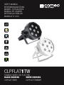 1
1
-
 2
2
-
 3
3
-
 4
4
-
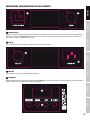 5
5
-
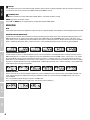 6
6
-
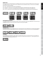 7
7
-
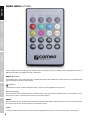 8
8
-
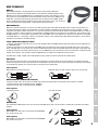 9
9
-
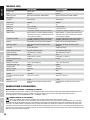 10
10
-
 11
11
-
 12
12
-
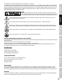 13
13
-
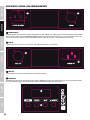 14
14
-
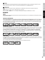 15
15
-
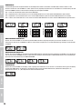 16
16
-
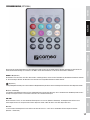 17
17
-
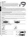 18
18
-
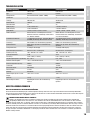 19
19
-
 20
20
-
 21
21
-
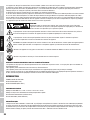 22
22
-
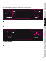 23
23
-
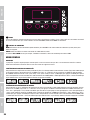 24
24
-
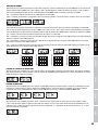 25
25
-
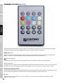 26
26
-
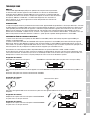 27
27
-
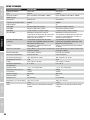 28
28
-
 29
29
-
 30
30
-
 31
31
-
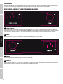 32
32
-
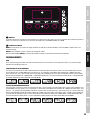 33
33
-
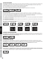 34
34
-
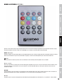 35
35
-
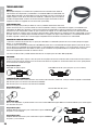 36
36
-
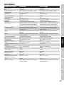 37
37
-
 38
38
-
 39
39
-
 40
40
-
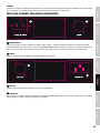 41
41
-
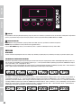 42
42
-
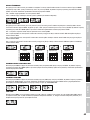 43
43
-
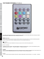 44
44
-
 45
45
-
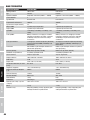 46
46
-
 47
47
-
 48
48
-
 49
49
-
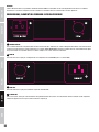 50
50
-
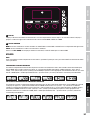 51
51
-
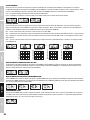 52
52
-
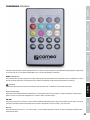 53
53
-
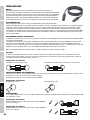 54
54
-
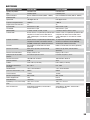 55
55
-
 56
56
-
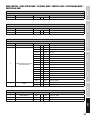 57
57
-
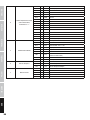 58
58
-
 59
59
-
 60
60


Cameo CLPFLAT1TW El manual del propietario
- Tipo
- El manual del propietario
- Este manual también es adecuado para
En otros idiomas
- français: Cameo CLPFLAT1TW Le manuel du propriétaire
- italiano: Cameo CLPFLAT1TW Manuale del proprietario
- Deutsch: Cameo CLPFLAT1TW Bedienungsanleitung
- polski: Cameo CLPFLAT1TW Instrukcja obsługi
Documentos relacionados
-
Cameo Q-Spot 15 W BK Manual de usuario
-
-
Cameo Tribar 200 IR WH Manual de usuario
-
-
Cameo Light INSTANT AIR 1000 PRO Manual de usuario
-
-
-
-
Cameo Flash Matrix 250 El manual del propietario
-