Craftsman 17AK2ACP099 El manual del propietario
- Categoría
- Cortadoras de césped
- Tipo
- El manual del propietario
Este manual también es adecuado para

perator_s nual
I:RRFrgMRN°
ZERO=TURN RIDER
26 HP, 50" MOWER DECK
Model No. 247.25002
CAUTION: Before using this product,
read this manual and follow all safety
rules and operating instructions.
, SAFETY
, ASSEMBLY
OPERATION
MAINTENANCE
PARTS LIST
o ESPANOL
Sears Brands Management Corporation, Hoffman Estates, IL 60179, U.S.A.
Visit our website: www.craftsman.com
FormNo.769-07727
(November23,2011)

Warranty Statement .................................. Page 2
Safe Operation Practices .......................... Pages 3-8
Assembly .................................................. Pages 9-12
Operation .................................................... Pages 13-21
Service and Maintenance ......................... Pages 22-34
Off-Season Storage .................................. Page 35
Troubleshooting ........................................ Page 36-37
Parts List ..................................................... Pages 38-52
Labels ....................................................... Page 53
Repair Protection Agreement ................... Page 55
Espa_ol ..................................................... Page 60
Service Numbers ...................................... Back Cover
CRAFTSMAN FULL WARRANTY
FORTWOYEARSfromthedateofpurchase,all non-expendablepartsofthis ridingequipmentarewarrantedagainstanydefectsin materialor
workmanship.A defectivenon-expendablepartwill receivefreein-homerepairor replacementif repairisimpossible.
FOR90 DAYSfromthedateofpurchase,thebattery(anexpendablepart)ofthis ridingequipmentiswarrantedagainstanydefectsinmaterialor
workmanship(ourtestingprovesthat itwillnotholda charge).A defectivebatterywillreceivefreein-homereplacement.
WARRANTYSERVICE
Forwarrantycoveragedetailstoobtainfree repairor replacement,call1-800-659-5917or visitthewebsite:www.craftsman.com
Inallcasesabove,if partrepairor replacementis impossible,theridingequipmentwillbe replacedfreeofchargewiththesameor anequivalent
model.
Alloftheabovewarrantycoverageisvoidifthisridingequipmentiseverusedwhileprovidingcommercialservicesor if rentedtoanotherperson.
ThiswarrantycoversONLYdefectsin materialandworkmanship.WarrantycoveragedoesNOTinclude:
• Expendableparts(exceptbattery)thatcanwearoutfromnormalusewithinthewarrantyperiod,includingbutnotlimitedtoblades,spark
plugs,air cleaners,belts,andoilfilters.
• Standardmaintenanceservicing,oilchanges,or tune-ups.
• Tirereplacementor repaircausedbypuncturesfromoutsideobjects,suchasnails,thorns,stumps,or glass.
• Tireorwheelreplacementor repairresultingfromnormalwear,accident,or improperoperationor maintenance.
• Repairsnecessarybecauseof operatorabuse,includingbutnotlimitedtodamagecausedbytowingobjectsbeyondthecapabilityofthe
ridingequipment,impactingobjectsthatbendtheframe,axleassemblyor crankshaft,orover-speedingtheengine.
• Repairsnecessarybecauseof operatornegligence,includingbutnotlimitedto,electricalandmechanicaldamagecausedbyimproper
storage,failureto usethepropergradeand amountofengineoil,failuretokeepthedeckclearofflammabledebris,orfailuretomaintainthe
ridingequipmentaccordingtotheinstructionscontainedin theoperator'smanual.
• Engine(fuelsystem)cleaningor repairscausedbyfueldeterminedto becontaminatedor oxidized(stale).Ingeneral,fuelshouldbeused
within30 daysof itspurchasedate.
Normaldeteriorationandwearoftheexteriorfinishes,or productlabelreplacement.
o
o
Thiswarrantygivesyouspecificlegalrights,and youmayalsohaveotherrightswhichvaryfromstatetostate.
Sears BrandsManagementCorporation, Hoffman Estates,IL 60179
EngineOil: SAE30
Fuel: UnleadedGasoline
SparkPlug: RC12YC
Engine: Briggs& StrattonTwinPlatinumProfessional
ModelNumber
Serial Number
Dateof Purchase
Recordthemodelnumber,serialnumber,
anddateof purchaseabove.
© KCDIRLLC 2

Thissymbolpointsoutimportantsafetyinstructionswhich,if not
followed,couldendangerthepersonalsafetyand/orpropertyof
yourselfandothers.Readandfollowall instructionsin thismanual
beforeattemptingtooperatethismachine.Failuretocomplywith
theseinstructionsmayresultin personalinjury.Whenyouseethis
symbol,HEEDITSWARNING!
CALIFORNIA PROPOSITION 65
EngineExhaust,someof itsconstituents,andcertainvehicle
componentscontainoremitchemicalsknowntoStateofCalifornia
tocausecancerandbirthdefectsorotherreproductiveharm.
Batteryposts,terminals,and relatedaccessoriescontainleadand
leadcompounds,chemicalsknowntotheStateof Californiato
causecancerandreproductiveharm.Washhandsafterhandling.
Thismachinewasbuilttobeoperatedaccordingtothesafeopera-
tionpracticesinthis manual.Aswithanytypeof powerequipment,
carelessnessorerroron thepartoftheoperatorcanresultin serious
injury.Thismachineiscapableofamputatingfingers,hands,toes
andfeetandthrowingdebris.Failuretoobservethefollowingsafety
instructionscouldresultin seriousinjuryor death.
Your Responsibility--Restricttheuseofthispowermachineto
personswhoread,understandandfollowthewarningsand instruc-
tionsin thismanualandon themachine.
SAVE THESE INSTRUCTIONS!
GENERAL OPERATION
• Read,understand,andfollowall instructionson themachineand
in themanual(s)beforeattemptingtoassembleandoperate.
Keepthis manualina safeplaceforfutureand regularreference
andfororderingreplacementparts.
• Befamiliarwithall controlsandtheirproperoperation.Knowhow
tostopthemachineanddisengagethemquickly.
• Neverallowchildrenunder14yearsofagetooperatethis
machine.Children14andovershouldreadandunderstandthe
instructionsandsafeoperationpracticesin thismanualandon
themachineandshouldbetrainedandsupervisedbyan adult.
• Neverallowadultstooperatethis machinewithoutproper
instruction.
• Tohelpavoidbladecontactor a thrownobjectinjury,keep
bystanders,helpers,childrenandpetsatleast75feetfromthe
machinewhileitisin operation.Stopmachineifanyoneenters
thearea.
• Thoroughlyinspecttheareawheretheequipmentistobe used.
Removeallstones,sticks,wire,bones,toys,andotherforeign
objectswhichcouldbe pickedupandthrownbytheblade(s).
Thrownobjectscancauseseriouspersonalinjury.
• Planyourmowingpatterntoavoiddischargeofmaterialtoward
roads,sidewalks,bystandersandthelike.Also,avoiddischarg-
ingmaterialagainstawallorobstructionwhichmaycause
dischargedmaterialto ricochetbacktowardtheoperator.
• Alwayswearsafetyglassesorsafetygogglesduringoperation
andwhileperforminganadjustmentor repairtoprotectyoureyes.
Thrownobjectswhichricochetcancauseseriousinjurytothe
eyes.
• Wearsturdy,rough-soledworkshoesandclose-fittingslacksand
shirts.Loosefittingclothesandjewelrycanbecaughtin movable
parts.Neveroperatethis machinein barefeetor sandals.
• Beawareofthemowerandattachmentdischargedirectionand
do notpointitatanyone.Donotoperatethemowerwithoutthe
dischargecoverorentiregrasscatcherin its properplace.
• Donotputhandsor feetnearrotatingpartsor underthecutting
deck.Contactwiththeblade(s)canamputatehandsandfeet.
A missingor damageddischargecovercancausebladecontact
or thrownobjectinjuries.
• Stoptheblade(s)whencrossinggraveldrives,walks,or roads
andwhilenotcuttinggrass.
• Watchfortrafficwhenoperatingnearorcrossingroadways.This
machineisnotintendedforuseonanypublicroadway.
• Donotoperatethemachinewhileundertheinfluenceofalcohol
or drugs.
• Mowonlyindaylightorgoodartificiallight.
Nevercarrypassengers.
• Backup slowly.Alwayslookdownandbehindbeforeandwhile
backingtoavoida back-overaccident.Beawareand payatten-
tiontothesafetysystemfunctionthatstopspowertothe blades
whendrivingin reverse.If notfuctioningproperly,contactan
authorizeddealerforsafetysysteminspectionand repair.
• Slowdownbeforeturning.Operatethemachinesmoothly.Avoid
erraticoperationandexcessivespeed.
Disengageblade(s),setparkingbrake,stopengineandwaituntil
theblade(s)cometo acompletestopbeforeremovinggrass
catcher,emptyinggrass,uncloggingchute,removinganygrassor
debris,or makinganyadjustments.
• Neverleavea runningmachineunattended.Alwaysturnoff
blade(s),placedrivecontrollevers inneutral,setparkingbrake,
stopengineand removekeybeforedismounting.
• Useextracarewhenloadingor unloadingthemachineintoa
traileror truck.Thismachineshouldnotbe drivenupor down
ramp(s),becausethemachinecouldtipover,causingserious
personalinjury.Themachinemustbepushedmanuallyon
ramp(s)toloadorunloadproperly.
3

• Mufflerandenginebecomehotandcancausea burn.Donot
touch.
• Checkoverheadclearancescarefullybeforedrivingunderlow
hangingtreebranches,wires,dooropeningsetc.,wherethe
operatormaybestruckor pulledfromthemachine,whichcould
resultinseriousinjury.
• Disengageallattachmentclutches,settheparkingbraketothe
'on'positionandmovethe RHand LHdrivecontrolleverstothe
neutralpositionbeforeattemptingtostarttheengine.
Yourmachineisdesignedto cutnormalresidentialgrassofa
heightnomorethan10".Donotattemptto mowthroughunusually
tall,drygrass(e.g.,pasture)orpilesofdryleaves.Drygrassor
leavesmaycontacttheengineexhaustand/orbuilduponthe
mowerdeckpresentinga potentialfirehazard.
• Useonlyaccessoriesandattachmentsapprovedforthis machine
bythemachinemanufacturer.Read,understandandfollowall
instructionsprovidedwiththeapprovedaccessoryor attachment.
Dataindicatesthatoperators,age60yearsandabove,are
involvedin a largepercentageofridingmower-relatedinjuries.
Theseoperatorsshouldevaluatetheirabilitytooperatetheriding
mowersafelyenoughto protectthemselvesandothersfrom
seriousinjury.
• Ifsituationsoccurwhicharenotcoveredinthismanual,usecare
andgoodjudgment.ContacttheCraftsmanHelpLineat1-800-
659-5917forassistance.
SLOPE OPERATION
Slopesarea majorfactorrelatedtolossofcontrolandtip-over
accidentswhichcanresultinsevereinjuryor death.Allslopesrequire
extracaution.Ifyoucannotbackuptheslopeor ifyoufeeluneasyon
it, do notmowit.
Foryoursafety,usetheslopegaugeincludedaspartofthismanual
to measureslopesbeforeoperatingthis machineona slopedor hilly
area.Iftheslopeisgreaterthan15degreesasshownonthe slope
gauge,donotoperatethis machineonthatareaor seriousinjurycould
result.
Do:
o
Mowacrossslopes,notupanddown.Exerciseextremecaution
whenchangingdirectionon slopes.
Watchforholes,ruts,bumps,rocks,orotherhiddenobjects.
Uneventerraincouldoverturnthemachine.Tallgrasscanhide
obstacles.
Useslowspeed.Choosea lowenoughspeedsothatyouwillnot
havetostopwhileon theslope.Avoidstartingor stoppingon a
slope.Ifthetiresareunableto maintaintraction,disengagethe
bladesandproceedslowlyandcarefullystraightdowntheslope.
Followthemanufacturer'srecommendationsforwheelweightsor
counterweightsto improvestability.
Useextracarewithgrasscatchersor otherattachments.These
canchangethestabilityofthe machine.
• Keepallmovementontheslopesslowandgradual.Donot
makesuddenchangesin speedor direction.Rapidacceleration
or decelerationcouldcausethefrontofthemachinetolift and
rapidlyrolloverbackwards,whichcouldcauseseriousinjury.
DoNot:
• Donotturnon slopesunlessnecessary;thenturnslowlyuphill
and useextracarewhileturning.
• Donotmowneardrop-offs,ditchesor embankments.Themower
couldsuddenlyturnoverifa wheelisovertheedgeofa cliff,
ditch,or ifan edgecavesin.
• Donottry tostabilizethemachinebyputtingyourfooton the
ground.
• Donotusea grasscatcheron steepslopes.
• Donotmowon wetgrass.Reducedtractioncouldcausesliding.
• Donottowheavypull behindattachments(e.g.loadeddumpcart,
lawnroller,etc.)on slopesgreaterthan5 degrees.Whengoing
downhill,theextraweighttendstopushtheridingmowerand
maycauseyoutoloosecontrol(e.g.ridingmowermayspeed
up,brakingandsteeringabilityare reduced,attachmentmay
jack-knifeandcauseridingmowertooverturn).
4

CHILDREN
Tragicaccidentscanoccuriftheoperatorisnotalerttothepresence
ofchildren.Childrenareoftenattractedtothemachineandthemowing
activity.Theydo notunderstandthedangers.Neverassumethat
childrenwillremainwhereyoulastsawthem.
• Keepchildrenoutofthemowingareaand inwatchfulcareofa
responsibleadultotherthantheoperator.
• Bealertandturnmachineoff ifa childentersthearea.
• Toavoidback-overaccidents,alwayslookbehindanddownfor
smallchildren.
• Nevercarrychildren,evenwiththeblade(s)shutoff.Theymay
falloffandbe seriouslyinjuredorinterferewithsafemachine
operation.
• Useextremecarewhenapproachingblindcorners,doorways,
shrubs,treesorotherobjectsthatmayblockyourvisionofa child
whomayrunintothe pathofthemachine.
• Keepchildrenawayfromhotor runningengines.Theycansuffer
burnsfroma hotmuffler.
• Removekeywhenmachineisunattendedtopreventunauthorized
operation.
Neverallowchildrenunder14yearsofagetooperatethis machine.
Children14andovershouldreadandunderstandtheinstructionsand
safeoperationpracticesinthismanualandon themachineandshould
betrainedandsupervisedbyan adult.
TOWING
Towonlywitha machinethathasa hitchdesignedfortowing.Donot
attachtowedequipmentexceptatthehitchpoint.
Followthemanufacturersrecommendationforweightlimitsfortowed
equipmentandtowingonslopes.
Neverallowchildrenor othersinoron towedequipment.
Onslopes,theweightof thetowedequipmentmaycauselossof
tractionandlossofcontrol.
Travelslowlyandallowextradistancetostop.
Donotshifttoneutralandcoastdownhill.
Donottowheavypullbehindattachments(e.g.loadeddumpcart,
lawnroller,etc.)onslopesgreaterthan5 degrees.Whengoingdown
hill,theextraweighttendsto pushtheridingmowerandmaycause
youto loosecontrol(e.g.ridingmowermayspeedup,brakingand
steeringabilityare reduced,attachmentmayjack-knifeandcause
ridingmowertooverturn).
SERVICE
SafeHandlingof Gasoline:
Toavoidpersonalinjuryorpropertydamageuseextremecarein
handlinggasoline.Gasolineisextremelyflammableandthevaporsare
explosive.Seriouspersonalinjurycanoccurwhengasolineisspilled
on yourselforyourclotheswhichcanignite.Washyourskinand
changeclothesimmediately.
• Useonlyanapprovedgasolinecontainer.
• Neverfillcontainersinsidea vehicleoron a truckortrailerbed
witha plasticliner.Alwaysplacecontainerson thegroundaway
fromyourvehiclebeforefilling.
• Whenpractical,removegas-poweredequipmentfromthetruck
or trailerandrefueliton theground.Ifthis isnotpossible,then
refuelsuchequipmentona trailerwitha portablecontainer,rather
thanfroma gasolinedispensernozzle.
• Keepthenozzleincontactwiththerimofthefueltankor
containeropeningatall timesuntilfuelingiscomplete.Donotuse
a nozzlelock-opendevice.
• Extinguishall cigarettes,cigars,pipesandothersourcesof
ignition.
• Neverfuelmachineindoors.
• Neverremovegascapor addfuelwhiletheengineishotor run-
ning.Allowengineto coolatleasttwominutesbeforerefueling.
• Neveroverfillfueltank.Filltanktono morethan1/2"belowbottom
offillernecktoallowspaceforfuelexpansion.
• Replacegasolinecapandtightensecurely.
• Ifgasolineisspilled,wipeitoff theengineandequipment.Move
machinetoanotherarea.Wait5 minutesbeforestartingthe
engine.
• Toreducefirehazards,keepmachinefreeofgrass,leaves,or
otherdebrisbuild-up.Cleanup oilor fuelspillageandremoveany
fuelsoakeddebris.
• Neverstorethemachineor fuelcontainerinsidewherethereisan
openflame,sparkor pilotlightasona waterheater,spaceheater,
furnace,clothesdryeror othergasappliances.
• Allowamachineto coolatleastfiveminutesbeforestoring.
GeneralService
• Neverrunan engineindoorsorina poorlyventilatedarea.Engine
exhaustcontainscarbonmonoxide,an odorless,anddeadlygas.
• Beforecleaning,repairing,or inspecting,makecertainthe
blade(s)andall movingpartshavestopped.Disconnectthespark
plugwireandgroundagainsttheengineto preventunintended
starting.
• Periodicallychecktomakesurethebladescometocompletestop
withinapproximately(5)fivesecondsafteroperatingtheblade
disengagementcontrol,ifthebladesdonotstopwithinthethis
timeframe,aveyourmachineservicedprofessionallybySearsor
anotherqualifieddealer.
• Regularlycheckthesafetyinterlocksystemforproperfunction,as
describedlaterinthis manual.Ifthesafetyinterlocksystemdoes
notfunctionproperly,haveyourmachineservicedprofessionally

bySearsoranotherqualifieddealer.
• Checkthe blade(s)andenginemountingboltsatfrequent
intervalsforpropertightness.Also,visuallyinspectblade(s)for
damage(e.g.,excessivewear,bent,cracked). Replacethe
blade(s)withtheoriginalequipmentmanufacturer's(O.E.M.)
blade(s)only,listedinthismanual.Useofpartswhichdo not
meettheoriginalequipmentspecificationsmayleadtoimproper
performanceandcompromisesafety!
• Mowerbladesare sharp.Wrapthebladeorweargloves,anduse
extracautionwhenservicingthem.
• Keepallnuts,bolts,andscrewstighttobesuretheequipmentis
in safeworkingcondition.
• Nevertamperwiththesafetyinterlocksystemor othersafety
devices.Checktheirproperoperationregularly.
• Afterstrikinga foreignobject,stoptheengine,disconnectthe
sparkplugwire(s)andgroundagainsttheengine.Thoroughly
inspectthemachineforanydamage.Repairthedamagebefore
startingandoperating.
• Neverattempttomakeadjustmentsorrepairstothemachine
whiletheengineis running.
• Grasscatchercomponentsandthedischargecoverare subject
towearanddamagewhichcouldexposemovingpartsor allow
objectsto bethrown.Forsafetyprotection,frequentlycheck
componentsand replaceimmediatelywithoriginalequipment
manufacturer's(O.E.M.)partsonly,listedinthis manual.Useof
partswhichdo notmeettheoriginalequipmentspecificationsmay
leadtoimproperperformanceandcompromisesafety!
• Donotchangetheenginegovernorsettingsor over-speedthe
engine.Thegovernorcontrolsthemaximumsafeoperatingspeed
oftheengine.
• Maintainorreplacesafetyandinstructionlabels,asnecessary.
• Observeproperdisposallawsandregulationsforgas,oil,etc.to
protecttheenvironment.
• AccordingtotheConsumerProductsSafetyCommission(CPSC)
andtheU.S.EnvironmentalProtectionAgency(EPA),thisproduct
hasan AverageUsefulLifeof seven(7)years,or270hoursof
operation.Attheendof theAverageUsefulLifehavethemachine
inspectedannuallybySearsor anotherqualifieddealertoensure
thatall mechanicalandsafetysystemsareworkingproperlyand
notwornexcessively.Failuretodo socan resultinaccidents,
injuriesor death.
DO NOT MODIFY ENGINE
Toavoidseriousinjuryor death,do notmodifyengineinanyway.
Tamperingwiththegovernorsettingcanleadtoa runawayengineand
causeittooperateat unsafespeeds.Nevertamperwithfactorysetting
ofenginegovernor.
Notice RegardingEmissions
Engineswhicharecertifiedto complywithCaliforniaandfederal
EPAemissionregulationsforSORE(SmallOffRoadEquipment)are
certifiedtooperateon regularunleadedgasoline,andmayinclude
thefollowingemissioncontrolsystems:EngineModification(EM)and
ThreeWayCatalyst(TWO)if soequipped.
SPARK ARRESTOR
Thismachineisequippedwithan internalcombustionengineand
shouldnotbeusedonor nearanyunimprovedforest-covered,
brush-coveredor grass-coveredlandunlesstheengine'sexhaust
systemisequippedwitha sparkarrestormeetingapplicablelocalor
statelaws(ifany).
Ifa sparkarrestoris used,itshouldbe maintainedin effectiveworking
orderbytheoperator.IntheStateof Californiatheaboveis required
bylaw(Section4442of theCaliforniaPublicResourcesCode).Other
statesmayhavesimilarlaws.Federallawsapplyonfederallands.
A sparkarrestorforthemufflerisavailablethroughyournearest
engineauthorizedservicedealeror contacttheservicedepartment,
RO.Box361131Cleveland,Ohio44136-0019.
6

SAFETY SYMBOLS
Thispagedepictsanddescribessafetysymbolsthatmayappearonthis product.Read,understand,andfollowallinstructionson themachine
beforeattemptingtoassembleandoperate.
sJ / _
®
READTHEOPERATOR'SMANUAL(S)
Read,understand,andfollowall instructionsinthemanual(s)beforeattemptingtoassembleand
operate
WARNING--ROTATINGBLADES
Donotputhandsor feetnearrotatingpartsor underthecuttingdeck.Contactwiththeblade(s)can
amputatehandsandfeet.
WARNING--THROWNOBJECTS
Thismachinemaypickupandthrowandobjectswhichcancauseseriouspersonalinjury.
WARNING--THROWNOBJECTS
Thismachinemaypickupandthrowandobjectswhichcancauseseriouspersonalinjury.
BYSTANDERS
Keepbystanders,helpers,childrenandpetsatleast75feetfromthemachinewhileitis inoperation.
WARNING--SLOPEOPERATION
Donotoperatethismachineona slopegreaterthan15degrees.
DANGER-- ROTATINGBLADES
Toreducetheriskofinjury,keephandsandfeetaway.Donotoperateunlessdischargecoveror grass
catcherisin itsproperplace.Ifdamaged,replaceimmediately.
7

(OK)
15° Slope
X
(TOO STEEP)
15° Slope
'_. _ Figure1
USETHISSLOPEGAUGETODETERMINE
IFA SLOPEISTOOSTEEPFORSAFEOPERATION!
Tochecktheslope,proceedasfollows:
1. Removethis pageandfoldalongthedashedline.
2. Locatea verticalobject onor behindtheslope(e.g.a pole,building,fence, tree,etc.)
3. Align eithersideoftheslopegaugewith theobject(SeeFigure1 and Figure2 ).
4. Adjust gaugeupor downuntilthe left cornertouchestheslope(SeeFigure1and Figure2).
5.
15°
dashedline
If thereisagap belowthegauge,theslopeistoo steepfor safeoperation(SeeFigure2above).
Figure2
Slopesare a majorfactor relatedtotip-over and roll-overaccidentswhichcan resultin severe injury ordeath. Donot operatemachine onslopes
in excessof 15degrees.All slopesrequireextracaution. Ifyou cannotbackup the slope or if you feeluneasyon it, do not mowit.
Always mowacross theface of slopes, nevermowupand downthe face of slopes.

SET-UP
Moving The Riding mower Manually
Yourridingmower'stransmissionisequippedwitha hydrostaticrelief
valveforoccasionswhenitisnecessarytomovethe ridingmower
manually.Openingthisvalvepermitsthefluidinthetransmissionto
bypassitsnormalroute,allowingthereartiresto"freewheel."Toopen
thehydrostaticreliefvalve,proceedasfollows:
1. Locatethehydrostaticbypassrodintherearoftheridingmower.
SeeFigure1.
RH Transmission
Bypass
PullOut Bypass
RodThenLower
IntoSlot
Keyhole Slot
Figure1
2. Pullthehydrostaticbypassrodoutward,thendown,tolockit in
place.
3. Repeattheaboveproceduretoengagetheotherbypassrodon
theothersideofthe ridingmower.
4. Withthe bypassrodsengagedandwiththeaidofanassistant,
carefullypushtheridingmoweroff oftheshippingpallet.
5. Aftermovingthe ridingmower,disengagebothbypassrods.Lift
therodandguidetheflangeoftherod backthroughthelarger
circularopeningof thekeyhole,thenreleasetherod.
NOTE:ThetransmissionwillNOTengagewhenthehydrostatic
bypassrodispulledout. Returntherodto itsnormalpositionpriorto
operatingthe ridingmower.
Neverattemptto movetheridingmowermanuallywithoutfirstopen-
ling thehydrostaticr,eliefvalve.Doingsowillresultinseriousdamage
[to theridingmowerstransmission.
Removethedeckwashsystemnozzleadapterandoildraintubefrom
themanualbagandstoreforfutureuse.
Install Operator's Seat
Toinstalltheseatproceedasfollows:
NOTE:Theseatisshippedwiththeseatswitchandseatpanattached.
1. Cutanystrapssecuringtheseatassemblyand thedrivecontrol
leverstotheridingmower.Removeanypackingmaterial.
NOTE:Becarefulnottocut thewiringharnessconnectingtheseat
andtheseatswitch.
.
9
Removethetwoshoulderboltsandlocknutsin theseatpanas
showninFigure2.
Shoulder
Bolt
Seat Pan
Shoulder
Bolt
Figure2
Rotatetheseatintopositionandsecuretheseatintoplacewith
thepreviouslyremovedshoulderboltsand locknuts.Becareful
nottocrimpordamagethewireharnesswhileinstallingtheseat.
See Figure3.
iHarness ii
Seat Bracket /
Shoulder
Bolts
Figure 3

Position Drive Control levers
Thedrivecontrolleversof theridingmowerareloweredforshipping
purposes.Theflangelocknuts,hexscrews,andflatwashersthat
normallysecurethecontrolleversintheiroperatingpositionare
unfastenedandinstalledintheslottedholesofthecontrolleversfor
shipment.Thecontrolleversmustbe repositionedtooperatethe
ridingmower.Torepositionthecontrolleversforoperation,proceedas
follows:
1. Removethehexscrew,flat washer,andflangelocknutfromthe
slotofoneofthedrivecontrollevers.
2. Liftand swingthatcontrolleverupwarduntiltheslottedholeinthe
leverbracketalignswithoneoftheholesinthepivotbracket.See
Figure4.
\
SlottedHole
Pivot
/
\
\\
\\
Figure4
3. Slidetheflatwasherontothe hexscrew.Fromtheoutside,insert
thehexscrewwithwasherthroughthecontrolleverslotandthe
holeofthepivotbracket.Securewiththeflangelocknut.See
Figure4.
4. Notethe relativepositionofthecontrollevertothepivotbracket,
thenrepeatthepreviousstepsto repositiontheothercontrollever
inapproximatelythesame position.
5. Referto"AdjustingtheDriveControlLevers"intheMaintenance&
Adjustmentsforinstructionsonthefinaladjustmentofthelevers.
Connecting the Battery Cables
Batteryposts,terminals,and relatedaccessoriescontainleadand
leadcompounds,chemicalsknowntotheStateof Californiatocause
cancerand reproductiveharm.Washhandsafter handling.
Whenattachingbatterycables,alwaysconnectthePOSITIVE(Red)
wireto itsterminalfirst,followedbytheNEGATIVE(Black)wire.
Forshippingreasons,bothbatterycableson yourequipmentmay
havebeenleftdisconnectedfromtheterminalsatthefactory.To
connectthebatterycables,proceedasfollows:
NOTE:ThepositivebatteryterminalismarkedPos.(+).Thenegative
batteryterminalismarkedNeg.(-).
NOTE:If thepositivebatterycableisalreadyattached,skipaheadto
step2.
1. Removetheplasticcover,ifpresent,fromthepositivebattery
terminalandattachtheredcabletothepositivebatteryterminal
(+)withtheboltandhexnut.SeeFigure5.
Figure5
2. Removetheplasticcover,ifpresent,fromthenegativebattery
terminalandattachtheblackcableto thenegativebattery
terminal(-) withtheboltand hexnut.SeeFig.3-5.
3. Positiontheredrubberbootoverthe positivebatteryterminalto
helpprotectitfromcorrosion.
NOTE:If thebatteryisputintoserviceafterthedateshownon top
or sideof battery,chargethebatteryasinstructedintheServiceand
MaintenancesectionyourOperator'sManualpriortooperatingthe
ridingmower.
10

Lower Deck Discharge Chute Deflector Adjusting the Gauge Wheels
Neveroperatethemowerdeckwithoutthechutedeflectorinstalled
andinthedownposition.
Checkthe mowerdeckfora shippingbrace(withtag)that maybe
holdingthechutedeflectorupwardforshipment. Ifa braceis present,
itmustberemovedbeforeoperatingthe ridingmower.Holdingthe
chutedeflectorfullyupward,removetheshippingbracebygraspingit
androtatingitclockwise.Lowerthechutedeflector.SeeFigure6.
Figure6
Checking Tire Pressure
Donotoverinfiatetires.Checksidewalloftiresformaximumpsi.
Equaltirepressureshouldbemaintainedatalltimes.
Thetireson yourridingmowermaybeoverinflatedforshipping
purposes.Reducethetirepressurebeforeoperatingthe ridingmower.
Checksidewalloftiresformaximumpsi.
Keephandsandfeetawayfromthedischargeopeningofthecutting
deck.
NOTE:Thedeckgaugewheelsarean anti-scalpfeatureof thedeck
andare notdesignedtosupporttheweightofthecuttingdeck.
Themowerdeckcuttingheightcanbe setinanyof sixheightsettings
usingthe ridingmower'sdecklift handle.Thedeckheightsrangefrom
1-1/2"to4".Thedeckgaugewheelpositionshouldbeapproximately
1/4"to 1/2"abovethegroundwhenthedeckissetinthedesiredheight
setting.
Usingthelifthandle,setthedeckinthedesiredheightsetting,then
checkthegaugewheeldistancefromthegroundbelow.If necessary
adjustasfollows:
1. Visuallycheckthedistancebetweenthefrontgaugewheelandthe
ground.Ifthegaugewheelisnearortouchingtheground,itshould
be raised.If morethan1/2"abovetheground,itshouldbelowered.
2. Removetheflangelocknutsecuringthefrontgaugewheel
shoulderbolttothedeck.Removethegaugewheelandshoulder
bolt. RefertoFigure7.
J
Figure7
3. Insert the shoulder bolt into the one of four index holes in the
front gauge wheel bracket that will give the gauge wheel a W'
to W' clearance with the ground and secure with the flange
locknut.
4. Note the index hole of the just adjusted wheel, and adjust the
rear gauge wheel into the respective index holes of the other
gauge wheel bracket on the deck.
11

Adjusting the Seat
Toadjustthepositionoftheseat,pullupand holdthe seatadjustment
lever.Slidetheseatforwardor rearwardtothedesiredposition;then
releasetheadjustmentlever.Makesureseatislockedintoposition
beforeoperatingtheridingmower.SeeFigure8.
Figure8
GAS AND OIL
Fuel Recommendations
Useautomotivegasoline(unleadedor lowleadedtominimizecombus-
tionchamberdeposits)witha minimumof87octane.Gasolinewith
upto 10%ethanolor 15%MTBE(MethylTertiaryButylEther)canbe
used.Neveruseanoil/gasolinemixtureor dirtygasoline.Avoidgetting
dirt,dust,or waterin thefueltank.DONOTuseE85gasoline.
• Refuelina well-ventilatedareawiththeenginestopped.Donot
smokeor allowflamesor sparksintheareawheretheengineis
refueledorwheregasolineis stored.
Donotoverfillthefueltank.Afterrefueling,makesurethetank
capisclosedproperlyand securely.
Becarefulnottospillfuelwhenrefueling.Spilledfuelor fuelvapor
mayignite.Ifanyfuelisspilled,makesuretheareaisdrybefore
startingtheengine.
Avoidrepeatedorprolongedcontactwithskinor breathingofvapor.
Adding Fuel
Useextremecarewhenhandlinggasoline.Gasolineisextremely
flammableandthevaporsareexplosive.Neverfuelthe ridingmower
indoorsor whiletheengineishotor running.Extinguishcigarettes,
cigars,pipesand othersourcesofignition.
1. Besureengineisoutdoorsandin awell-ventilatedarea.
2. Cleanareaaroundthefuelfillcapandremovethefuelfillcap.
3. Usingan approvedredGASOLINEcontainer,addfuelslowly,being
carefultoavoidspilling.
4. Fillthetankuntilthefuelreachesthebottomofthefueltankneck.
5. Replacethefuelcapandtightensecurely.Wipeupspilledfuel
beforestartingengine.IffuelisspilledDONOTstartengine.Move
ridingmowerawayfromareaof spillage.Avoidcreatinganysource
ofignitionuntilfuelvaporsaregone.
Checking and Adding Oil
Yourridingmowerisshippedwithoilintheengine.However,youMUST
checktheengineoil levelbeforeeachuseasinstructedin theIAlways
Serviceand Maintenancesection.Addoilas necessary.Failuretodo I
I
[so mayresut nser ousdamagetoyourengne. J
1. Placetheridingmoweron a flat,levelsurface.
2. Removetheoilfillercap/dipstickandwipethedipstickclean.See
Figure9.
Figure9
3. Insertthecap/dipstickintotheoilfillerneck,butdonotscrewitin.
4. Removetheoilfillercap/dipstick.Ifthe levelislow,slowlyaddoil
untiloillevelregistersbetweenFULLandADD,Figure8.
NOTE:Donotoverfill.Overfillingwithoil maycausesmoking,hard
starting,or sparkplugfouling.
5. Replaceandtightencap/dipstickfirmlybeforestartingengine.
NOTE:DONOTallowoil leveltofallbelowtheADDmarkonthe
dipstick.Doingsomayresultinequipmentmalfunctionsor damage.
NOTE:Tochangetheoil inyourengine,seethe Serviceand
Maintenancesectionofthismanual.
12

Parking
Deck Lift
Deck Height Handle
O
Throttle/Choke Control
Hour Meter/
indicator Panel
SeatAdjustmentLever
FuelTankCap
H
// _ / -PTOSwitch
LH Drive RH Drive nition Switch
Control Lever Control Lever
Cup Holder
Storage Tray
Figure11
Nowthat youhavesetup yourridingmower,it'simportanttobecome
acquaintedwith itscontrolsandfeatures.RefertoFigure11.
NOTE:ReferencestoLEFT,RIGHT,FRONT,andREARindicatethatposi-
tionontheridingmowerwhenfacingforwardwhileseatedintheoperator's
seat.
DECK HEIGHT INDEX
Thedeckheightindexconsistsofsixindexnotcheslocatedon
thefront!rightd theseatboxframe.Eachnotchcorrespondsto
a 1/2"changein thedeckheightpositionrangingfrom1-1/2"at
thelowestnotchto4 inchesatthehighestnotch.
DECK LIFT HANDLE
Thedecklift handleislocatedon thefront!rightofthe seat
boxframe,andisusedto raiseand lowerthemowerdeck.
Pullthehandletotheleftoutoftheindexnotchandpush
downwardtolowerthedeck,or pullupwardtoraisethedeck.
Whenthedesiredheightisattained,movethelifthandletothe
rightuntilfullyintheindexnotch.
CUP HOLDER
ThecupholderislocatedtowardtherearoftheRHconsole
totherightoftheoperator'sseat.
STORAGE TRAY
Thestoragetrayislocatedattherearofthe RHconsole.
RH AND LH DRIVE CONTROL LEVERS
TheRHandLHcontrolleversarelocatedon eachsideoftheopera-
tor'sseat.Thesehingedleverspivotoutwardtoopenspacetopermit
theoperatortoeither sitintheridingmowerseat,orto dismountthe
ridingmower.Theleversmustbefullyopenedoutand intheneutral
positionto starttheridingmowerengine.
Eachlevercontrolsthe respectiveRHorLHtransmission.Conse-
quently,theseleverscontrolallofthemovementsoftheridingmower.
Drivingand steeringutilizingthesecontrolleversisquitedifferentfrom
conventionalridingmowers,andwilltakesomepracticetomaster.
RefertotheDrivingthe Ridingmowersectionforinstructionsonusing
thecontrollevers.
Meets ANSI Safety Standards
CraftsmanTillersconformtothesafetystandardoftheAmericanNationalStandardsInstitute(ANSI)
13

iGNiTiON SWITCH
Theignitionswitchislocatedon
theRHconsoletotherightofthe
operator'sseat.Theignitionswitch
hasthreepositions.
STOP_ -- Theengineandelectri-
calsystemisturnedoff.
RUN_ I
RUN_ -- Theridingmowerelectricalsystemisenergized.
START_ -- Thestartermotorwillturnovertheengine.Releasethe
keyimmediatelywhentheenginestarts
NOTE:Topreventaccidentalstartingand/orbatterydischarge,
removethekeyfromtheignitionswitchwhenthe ridingmowerisnot
inuse.
POWER TAKE-OFF (PTO) SWITCH
ThePTOswitchislocatedontheRHconsoletotherightoftheopera-
tor'sseat.ThePTOswitchoperatestheelectricPTOclutchmounted
onthebottomoftheenginecrankshaft.Pullthe switchknobupward
toengagethePTOclutch,or pushtheknobdownwardtodisengage
theclutch.ThePTOswitchmustbeinthe"disengaged"positionwhen
startingtheengine.
TRANSMiSSiON BYPASS RODS
Thetransmissionbypassrods(oneforeachtheRHandLHtransmis-
sion)arelocatedbeneaththeframeplatform,justinsideeachrear
wheel.
Whenengaged,thetwo rodsopena bypasswithinthe hydrostatic
transmissions,whichallowstheridingmowertobe pushedshort
distancesbyhand.RefertotheAssemblysectionforinstructionson
usingthebypassfeature.
Nevertowyourridingmower.Towingtheridingmowerwiththerear
wheelsonthegroundmaycauseseveredamagetothetransmissions.
SEAT ADJUSTMENT LEVER
Theseatadjustmentleverislocatedbelowthefront!leftoftheseat.
Theleverallowsforadjustmentoftheforetoaft positionofthe
operator'sseat.RefertoServiceand Maintenanceforinstructionson
adjustingtheseatposition.
FUEL TANK CAP
ThefueltankcapislocatednearthemiddleoftheLHconsole.Turn
thefillcapapproximately1/4turnandpull upwardtoremove.Thefuel
capistetheredtothe ridingmowertopreventitsloss.Donotattempt
toremovethecapfromtheridingmower.
Pushthecapdownwardonthefueltankfillneckand turnapproxi-
mately1/4turnclockwisetotightenAlwaysre-installthefuelcaptightly
ontothefueltankafter removing.
Neverfillthefueltankwhentheengineisrunning.Iftheengineis
hotfrom recentlyrunning,allowtocoolforseveralminutesbefore
refueling.Highlyflammablegasolinesplashingontoa hotengine
couldcausea fire.
HOUR METER/INDICATOR
PANEL
Thehourmeter/indicatorpanelislocatedonthe
LHconsoletotheIdtoftheoperator'sseat.
Hour Meter Features
Thehourmeterrecordsthehoursthatthe
ridingmowerhasbeenoperatedinthedigital
display(tenthsofanhour-- rightmostdigit).
NOTE:Thehourmeterisactivatedwhenevertheignitionswitchis
turnedtotheRUN_ position.Keepa recordoftheactualhoursof
operationtoassureall maintenanceproceduresarecompletedaccord-
ingtotheinstructionsinthis manualandtheenginemanual.
WhenkeyisturnedtotheRUN_ position,thebatteryindicatorlight
brieflyilluminatesandthebatteryvoltageis brieflydisplayed.The
displaythenchangestotheaccumulatedhours.
TheIndicatorMonitorwillalsoremindtheoperatord maintenanceinter-
valsforchangingtheengineoil.TheLCDwillalternatelyflash,CHG;OIL
andtherecordedhoursforfiveminutesafterevery50hoursofrecorded
operation.Themaintenanceintervallastsfortwohours(from50-52,100-
102,150-152,etc.).TheLCDwillflashasdescribedforfiveminutesevery
timetheridingmower'sengineisstartedduringthismaintenanceinterval.
Followtheoilchangeintervalsprovidedintheenginemanual.
indicator Panel Features
Battery Indicator
Illuminatesandthebatteryvoltageisdisplayedbrieflywhentheignition
switchitturnedtotheRUN_ position.
Illuminatestoindicatethebatteryvoltagehasdroppedbelow11.5(+0.5/-
1.0)volts,andthevoltageisdisplayedonthehourmeter.Ifthisindicator
anddisplaycomeonduringoperation,checkthebatteryandcharging
systemforpossiblecausesand/orcall1-800-659-5917to schedule
ridingmowerinspectionservicefromSearsParts& Repair.
Oil PressureIndicator (if EngineSo Equipped)
Thiswarninglampindicateslowengineoilpressure,iftheindicatorcomes
onwhiletheengineisrunning,stoptheengineimmediatelyandcheckfor
possiblecauses.Donotruntheenginewhilethisindicatorisilluminated.
Call1-800-659-5917toscheduleservicefromSearsParts& Repair.
NOTE:Theoil_ressureindicatormayilluminatewhentheignitionswitch
isin theRUNO position,butshouldturnoffwhentheengineisstarted.
PTOEngagedIndicator
ThisindicatorilluminateswhenthePTOswitchispulledupwardinthe
ENGAGEDpositionandtheignitionswitchisturnedtotheSTART
position.Checkthisindicatoriftheenginewillnotcrankwiththeignition
switchintheSTART_ position.Ifnecessary,movethePTOswitchto
theDISENGAGEDposition.
ParkingBrakeEngaged Indicator
Thisindicatorilluminateswhentheparkingbrakeisin theDISEN-
GAGEDpositionandtheignitionswitchisturnedtothe START
position.Checkthis indicatoriftheenginewillnotcrankwiththe
ignitionswitchin theSTART_ position.Ifnecessary,movethe
parkingbraketo theENGAGEDposition.
Thisindicatoralsoilluminateswhentheignitionswitchisturnedtothe
START_ positionandtheRHand/orLHdrivecontrolleversare in
a positionotherthanthefullyoutin neutralposition.Movethecontrol
leversfullyoutward.
14

THROTTLE/CHOKE CONTROL
Thethrottle/chokecontrolislocatedontheLHconsoleto
theleftoftheoperator'sseat.Whensetina givenposition,a
uniformenginespeedwillbemaintained.
Pushthethrottle/chokecontrolhandleforwardtoincrease
theenginespeed.Theridingmowerisdesignedtooperate
withthethrottle/chokecontrolintheFAST_ position
whentheridingmowerisbeingdrivenandthemowerdeck
isengaged.
Pullthethrottle/chokecontrolhandlerearwardtodecrease
theenginespeed.
Whenstartingtheengine,pushthecontrolhandlefully
forwardintotheCHOKEI'_,1position.
Afterstartingandwarmingtheengine,movethecontrolhandle
rearwarduntilyoufeelit movepastthechokedetent.
PARKING BRAKE ENGAGEMENT LEVER
Theparkingbrakeengagementleverislocatedonthefront/
leftoftheseatboxframe,andis usedtoengagetheparking
brake.
Pulltheleverfullyupwardandtothe left;thenlowerintothe
short"J"slottoengagethebrake.
Pulltheleverupoutofthe"J"slotandtotheright;thenlower
completelytodisengagetheparkingbrake.
NOTE:IftheLHandRHdrivecontrolleversarenotfully
openedoutto eachsidein theneutralpositionwhenengag-
ingtheparkingbrake,theenginewillstop.Theparkingbrake
mustbe placedin theengagedpositionwhenstartingthe
ridingmowerengine.
GENERAL SAFETY
• RECEIVEINSTRUCTION-- Entirelyreadthisoperator'smanual.
Learnto operatethismachineSAFELY.DonotriskINJURYor
DEATH.Allowonlythosewhohavebecomecompetentin its
usagetooperatethis ridingmower.
• Beforestartingtheengineor beginningoperation,be familiarwith
thecontrols.Theoperatorshouldbein theoperator'sseat.The
PTOswitchmustbein thedisengagedposition,theparkingbrake
engaged,andthe RHandLHdrivecontrolleversmovedfully
outwardin theneutralposition.
• Keepallshieldsin place.Keepawayfrommovingparts.
• NORIDERS!Keepall peopleandpetsa safedistanceaway.
Lookbehindand downtobothsidesoftheridingmowerbefore
andwhilebackingup.
• DONOTdirectthemowerdischargeatpeople.
• Avoidslopeswherepossible.Neveroperateon slopesgreater
than15°. Slopeswitha greaterinclinepresentdangerousoperat-
ing conditions.Ridingmowerscanbe rolledover.
• Beforeleavingtheoperator'sseat:Shutoff thePTO,move
the RHand LHdrivecontrolleversfullyoutwardin theneutral
position,engagetheparkingbrake_:_, shutoff theengineand
removetheignitionkey.Waitforall movementto stopbefore
servicingor cleaning.
• Operatethedrivecontrolleverssmoothlyandavoidanysudden
movementsoftheleverswhenstartingandstopping.Keepa firm
gripon thecontrollevers.
• Becarefulwhenoperatingnearroadways.Stoptheridingmower
motionandwaitforvehiclestopassbeforeoperatingalongthe
road.
• Donotoperatetheridingmowerwiththemowerdeckremoved.
Removalofthedeckwillchangethebalanceoftheridingmower,
andcouldcontributetoa ridingmowerrollover.
• Avoidoperationontractionsurfacesthatare unstable;use
extremecautionifthesurfaceis slippery.
• Slowdownbeforeturningandcometoa completestopbefore
anyzeroturnmaneuver.
• Donotstoptheridingmoweror parktheridingmowerover
combustiblematerialssuchasdrygrass,leaves,debris,etc.
• Donotfillthefueltankwhentheengineis runningor whilethe
engineishot.Allowtheengineseveralminutestocoolbefore
refueling.Tightenthefuelcapsecurely.
15

BEFORE OPERATING YOUR RiDiNG MOWER
• Beforeyouoperatetheridingmower,studythismanualcarefully
tofamiliarizeyourselfwiththeoperationofalltheinstrumentsand
controls.Ithasbeenpreparedtohelpyouoperateand maintain
yourridingmowerefficiently.
• Thisengineiscertifiedtooperateonlyonclean,fresh,unleadedregu-
largasoline.Forbestresults,fillthefueltankwithonlyclean,fresh,
unleadedgasolinewitha pumpstickeroctaneratingof87orhigher.
• Unleadedgasolineisrecommendedbecauseitleavesless
combustionchamberdepositsand reducesharmfulexhaust
emissions.Leadedgasolineis notrecommendedand mustnotbe
usedwhereexhaustemissionsareregulated.
NOTE:Purchasegasolineinsmallquantities.Donotusegasolineleftover
fromthepreviousseason,tominimizegumdepositsinthefuelsystem.
• Gasohol(upto 10%ethylalcohol,90% unleadedgasolineby
volume)isanapprovedfuel.Othergasoline/alcoholblendsare
notapproved.
• MethylTertiaryButylEther(MTBE)andunleadedgasolineblends
(uptoa maximumof 15%MTBEbyvolume)areapprovedfuels.
Othergasoline/etherblendsarenotapproved.
• Checktheengineoillevel.
• Cleantheaircleanerelementif necessary.
• Checkthetireinflationpressures.
• Adjusttheseatforoperator'smaximumcomfort,visibilityandfor
maintainingcompletecontrolofthe ridingmower.
SAFETY iNTERLOCK SYSTEM
Thisridingmowerisequippedwitha safetyinterlocksystemforthe
protectionoftheoperator.Iftheinterlocksystemshouldevermalfunc-
tion,donotoperatetheridingmower.Call1-800-659-5917toschedule
servicefromSearsParts& Repair.
• Thesafetyinterlocksystempreventstheenginefromcranking
orstartingunlessthe RHand LHdrivecontrolleversare moved
fullyoutwardtoeachsidein theneutralposition,theparking
brakeisengaged,andthePTOisdisengaged.
• Toavoidsuddenmovementwhendisengagingtheparkingbrake,
thesafetyinterlocksystemwillshutofftheengineiftheRHand/
or LHdrivecontrolleversare movedtoa positionotherthan
thefullyoutintheneutralpositionwhentheparkingbrakeis
engaged.
• Thesafetyinterlocksystemwillshutofftheengineiftheoperator
leavestheseatbeforeengagingtheparkingbrake.
• Thesafetyinterlocksystemwillshutofftheengineiftheoperator
leavestheseatwiththePTOengaged,regardlessofwhetherthe
parkingbrakeisengaged.
NOTE:ThePTOswitchmustbe movedtothe"OFF"positionto restart
theengine.
• ThesafetyinterlocksystemwillshutoffthePTOandthemower
bladeswillstopif bothdrivecontrolleversare movedintothe
reverseposition.ThePTOwillre-engagewhenoneor bothofthe
leversaremovedbacktoeithertheneutralorforwardposition.
STARTING THE ENGINE
Thisridingmowerisequippedwitha safetyinterlocksystemdesignee
fortheprotectionoftheoperator.Donotoperatetheridingmowerif
anypartoftheinterlocksystemismalfunctioning.Periodicallycheck
thefunctionsofthe interlocksystemforproperoperation.
Forpersonalsafety,theoperatormustbesittingintheridingmower
seatwhenstartingtheengine.
16
1. Operatormustbesittinginthe ridingmowerseatwithbothdrive
controlleversoutwardtoeachsidein theneutral/startposition.
2. EngagetheparkingbrakeO. Referto Figure12.
LHControlLever RHControlLever
Outin I_eutral Out in Neutral
ParkingBreak
-- Engaged
ThrottleControl / ( PTOSwitchinDown
FullyForwardto / __ (Disengaged)Position
CHOKEPosition
Figure12
3. MakecertainthePTOswitchisin thedisengaged(down)posi-
tion. Referto Figure12.
4. Movethethrottle/chokecontrolleverfullyforwardintotheCHOKEt"°,1
position.
NOTE:Iftheengineiswarmedup,itmaynotbe necessarytoplace
thethrottle/chokecontrolin theCHOKE!'_1position.
5. TurntheignitionkeyclockwisetotheSTART_ positionand
releaseitassoonastheenginestarts;however,do notcrank
theenginecontinuouslyfor morethan5 secondsata time.If the
enginedoesnotstartwithinthis time,turnthekeytoSTOP
andwaitat least15secondstoallowtheengine'sstartermotor
tocool.Tryagainafterwaiting.Ifaftera fewattemptstheengine
failstostart,do notkeeptryingtostartitwiththechokeclosedas
thiswillcausefloodingandmakestartingmoredifficult.
6. Astheenginewarmsup,graduallypullthethrottle/chokecontrollever
rearwardpastthechokedetentposition.Donotusethechokeposition
toenrichthefuelmixture,exceptasnecessarytostarttheengine.
7. Allowtheengineto runfora fewminutesatmidthrottlebefore
puttingtheengineunderload.
8. Observethehourmeter/ indicatorpanel.Ifthebatteryindicator
lightoroil pressurelightcomeon,immediatelystoptheengine.
Call1-800-659-5917toscheduleridingmowerinspectionservice
fromSearsParts& Repair.

ColdWeatherStarting
Whenstartingtheengineattemperaturesnearorbelowfreezing,
ensurethecorrectviscositymotoroilisusedintheengineandthe
batteryisfullycharged.Starttheengineasfollows:
1. Besurethebatteryisingoodcondition.Also,awarmbatteryhas
muchmorestartingcapacitythanacoldbattery.
2. Usefreshwintergradefuel.Wintergradegasolinehashighervolatility
toimprovestarting.Donotusegasolineleftoverfromsummer.
3. FollowthepreviousinstructionforStartingtheEngine.
UsingJumper CablesTo Start Engine
Batteriescontainsulfuricacidandproduceexplosivegasses.Make
certaintheareaiswellventilated,wearglovesandeyeprotection,
land avodsparksor famesnearthebattery.
Ifthe batterychargeisnotsufficienttocranktheengine,rechargethe
battery.Ifa batterychargeris unavailableandtheridingmowermust
be started,theaidof aboosterbatterywillbenecessary.Connectthe
boosterbatteryasfollows:
1. Connecttheendofonecabletothedisabledridingmowerbat-
tery'spositiveterminal;thenconnecttheotherendofthatcableto
theboosterbattery'spositiveterminal.
2. Connectoneendoftheothercabletotheboosterbattery'snega-
tiveterminal;thenconnecttheotherendofthatcabletothe frame
ofthedisabledridingmower,asfarfromthebatteryaspossible.
3. Startthedisabledridingmowerfollowingthe normalstarting
instructionspreviouslyprovided;thendisconnectthejumper
cablesin theexactreverseorderof theirconnection.
4. Havetheridingmower'selectricalsystemcheckedand repaired
assoonaspossibletoeliminatetheneedforjumpstarting.
STOPPING THE ENGINE
1. PlacethePTOswitchintheOFFposition.
2. Movethe RHandLHdrivecontrolleversfullyoutwardinthe
neutralposition.
3. EngagetheparkingbrakeO.
4. Movethethrottle/chokecontroltomidwaybetweentheSLOW'_
andFAST_ positions.
5. Turntheignitionkeytothe STOP_ positionand removethekey
fromtheignitionswitch.
NOTE:Alwaysremovethekeyfromtheignitionswitchtopreventacci-
dentalstartingor batterydischargeiftheequipmentisleft unattended.
PRACTICE OPERATION (INITIAL USE)
Operatinga zero-turnridingmowerisnotlikeoperatingaconventionaltype
ridingridingmower.Becausea zeroturnridingmowerismoremaneuver-
able,gettingusedtooperatingthecontrolleverstakessomepractice.
Westronglyrecommendthatyoulocatea reasonablylarge,levelandopen
"practicearea"wheretherearenoobstructions,pedestrians,oranimals.You
shouldpracticeoperatingtheridingmowerforaminimumof30minutes.
Carefullymove-- orhaveanexperiencedusermove--the ridingmower
tothepracticearea.Whenperformingthepracticesession,thePTO
shouldnotbeengaged.Whilepracticing,operatetheridingmower
atapproximately1/2to3/4throttleandatlessthanfullspeedinboth
forwardandreverse.
Carefullypracticemaneuveringtheridingmowerandproceedtodriveas
describedin thefollowingDrivingtheRidingmowerForwardsection.
DRIVING THE RIDING MOWER
Avoidsuddenstarts,excessivespeedand suddenstops, j
1. Adjusttheoperator'sseattothemostcomfortablepositionthat
allowsyoutooperatethecontrols.See"AdjustingtheSeat" the
Assemblysection.
2. ReleasetheparkingbrakeO.
3. MovetheRHand LHdrivecontrolleversinwardin theneutral
position.RefertoFigure13.
Control Lever Moved
inward and in Neutral
/
Q
Figure13
NOTE:Ifthecontrolleversarenotevenintheneutralposition,refer
to ServiceandMaintenanceforinstructionstoadjusttheleverssothat
theyareeven.
4. Movethethrottle/chokecontrolleverforwardtotheFAST
(fullthrottle)position.
NOTE:Althoughtheridingmower'sengineisdesignedto runatfull
throttle,whenperforminga practicesessiontheridingmowermustbe
operatedatlessthanfullthrottle.Thisonlyappliesto practice.
Alwaysmaintainafirm griponthecontrollevers.DONOTreleasethe
controlleversto slowor stoptheridingmower;moveleversto neutral
positionusingyourhands.
5. Todrivetheridingmower,firmlygrasptherespectivedrivecontrol
leverswithyourrightandleft handsandcontinuewithDrivingthe
RidingmowerForwardon thefollowingpage.
17

Driving the Riding mower Forward
Keepall movementofthedrivecontrolleversslowandsmooth.
Abruptmovementofthecontrolleverscanaffectthestabilityofthe
ridingmowerandcouldcausetheridingmowertoflipover,which
mayresultin seriousinjuryordeathtotheoperator.
Slowlyandevenlymovebothdrivecontrolleversforward.The
ridingmowerwillstartto moveforward.SeeFigure14.
r
Driving Forward
Faster
Figure14
2. Asthecontrolleversarepushedfartherforwardthespeedofthe
ridingmowerwillincrease.
3. Toslowtheridingmowermovethecontrolsleverrearwardto
attainthedesiredspeed,ormovetheleverstotheneutralposition
tostoptheridingmower.
Alwaysmaintainyourgraspon thedrivecontrollevers.Donotrelease
the leversto slowthe ridingmowerorto returntoneutral.
Turning the Riding mower While Driving Forward
Whenreversingthedirectionof travel,werecommendperforming
gradual'U' turnswherepossible.Sharperturnsincreasethepossibil-
ity ofturfdefacement,andcouldaffectcontroloftheridingmower.
ALWAYSslowtheridingmowerbeforemakingsharpturns.
Toturntheridingmowerwhiledrivingforward,movethecontrollevers
as necessarysothat oneleverisrearwardd theother.Theriding
mowerwillturninthedirectionofthe rearwardcontrollever.
1. Toturntotheleft,movetheleftdrivecontrolleverrearwardofthe
rightlever.SeeFigure15.
Figure15
2. Toturntotheright,movetherightdrivecontrolleverrearwardof
theleft lever.SeeFigure16.
W
ForwardRightTurn F
-oZ-
18
Figure16
3. Thegreaterthefore-to-aftdistancebetweenthetwolevers,the
sharpertheridingmowerwillturn.

4. Toexecuteazeroturnmovetheturnsidedrivecontrolleverto
theinwardneutralposition,whilemovingtheothercontrollever
forward.
NOTE:Makingazeroturnongrasswillgreatlyincreasethepotential
fordefacementoftheturf.
Driving the Riding mower in Reverse
1. Slowlyandevenlymovebothdrivecontrolleversrearward.The
ridingmowerwillstarttomoveinthe reversedirection.SeeFigure
17.
.
F
Turning While Driving Rearward
1. Toturntheridingmowerwhiledrivingrearward,movethecontrol
leversasnecessarysothatoneleverisforwardoftheother.The
ridingmowerwillturninthedirectionoftheforwardcontrollever.
Toturntotheleftwhiletravelinginreverse,movetheleft drive
controlleverforwardofthe rightlever.See Figure18.
Rearward Left Turn
0
®
.
f
Figure18
Toturntotherightwhiletravelinginreverse,movetherightdrive
controlleverforwardoftheleft lever.SeeFigure19.
.
3.
Figure17
Asthecontrolleversarepushedfartherrearwardthespeedofthe
ridingmowerwillincrease.
Toslowtheridingmowermovethecontrolsleverforwardtoattain
thedesiredspeed,or movetheleverstotheneutralpositionto
stoptheridingmower.
Rearward Right Turn
0
Figure19
4. Thegreaterthefore-to-aftdistancebetweenthetwolevers,the
sharpertheridingmowerwillturn.
5. Toexecutea zeroturn,movetheturnsidedrivecontrolleverto
theneutralposition,whilemovingtheothercontrolleverrearward.
NOTE:Makinga zeroturnon grasswillgreatlyincreasethepotential
fordefacementoftheturf.
19

Executing a Zero Turn
When executinga zeroturn,theridingmowerMUSTBESTOPPED.
Executinga zeroturnwhiletheridingmowerismovingcansignifi-
cantlyreduceyourcontrolof theridingmowerandwillcausesevere
turf defacementtooccur.
Stoptheforwardor reversemotionoftheridingmowerbymoving
thetwodrivecontrolleverstoneutral.
2. Toturnclockwise,movetheleftcontrolleverforwardwhilesimulta-
neouslymovingtherightcontrolleverrearward.SeeFigure20.
Clockwise Zero Turn
Figure20
3. Toturncounterclockwise,movetherightcontrolleverforwardwhile
simultaneouslymovingtheleftcontrolleverrearward.SeeFigure21.
Counterclockwise
Zero Turn
2. Pushthe PTOswitchdownwardtotheDISENGAGEDposition.
3. Usethedecklift handletoraisethedecktoitshighestposition.
4. Ifdismountingtheridingmower,movethedrivecontrolleversfully
outwardintheneutralposition,engagetheparkingbrakeO, move
thethrottle/chokecontrollevertotheFAST_ position,turnthe
ignitionswitchto STOP_ and removethekeyfromtheswitch.
Donotleavetheseatoftheridingmowerwithoutdisengagingthe
PTO, movingdrivecontrolleversfullyoutwardintheneutralposition,
andengagingtheparkingbrake.Ifleavingtheridingmowerunat-
tended,turntheignitionkeyoffand removekey.
DRIVING ON SLOPES
Referto theslopegaugeinthe SafeOperationSectiontohelp
determineslopeswhereyoumaynotoperatesafely.
Donotoperateon inclineswitha slopein excessof15degrees(a
riseofapproximately2-1/2feetevery10feet).Theridingmowercould
overturnandcauseseriousinjury.
1. Alwaysdriveacrossslopes,neverupanddown.Controlthe
speedanddirectionoftheridingmowerusingprimarilythecontrol
leveron thedownhillsideoftheridingmower,withtheuphill
controlleverremainingessentiallyina fixedposition.
2. Avoidturningdownhillifpossible.Startatthebottomof a slope
andworkupward.Alwaysslowdownbeforeturning.
3. Useextracareandgo slowlywhenturningdownhill.
OPERATING THE PTO
Operatethe PTOclutchasfollows:
1. Movethethrottle/chokecontrollevertoapproximatelythemid
throttleposition.
2. Pullthe PTOswitchupwardtothe ENGAGEDposition.
3. Advancethethrottle/chokelevertotheFAST_ position(full
throttle).
4. Theoperatormustremainintheridingmowerseatatall times.If
theoperatorshouldleavetheseatwithoutturningoffthe power
take-offswitch,theridingmower'senginewillshutoff.
5. ThePTOclutchcannotbeoperatedwhenthe ridingmoweris
drivinginthereversedirection.ThePTOwilldisengagewhen
bothdrivecontrolleversaremovedtothereverseposition,and
willre-engagewhenone(or both)controllever(s)ismovedtothe
neutralorforwardposition.
Figure21
STOPPING THE RIDING MOWER
1. Movebothdrivecontrolleverstotheneutralpositiontostopthe
motionoftheridingmower.
20

USING THE MOWER DECK
l Makecertaintheareatobe mowedisfreeofdebris,sticks,stones,
I
wireorotherobjectsthatcanbethrownbytherotatingblades. ]
NOTE:Donotengagethemowerdeckwhenloweredingrass.
Prematurewearand possiblefailureofthe'V" beltand PTOclutch
willresult.Fullyraisethedeckormovetoa non-grassyareabefore
engagingthemowerdeck.
1. Mowacrossslopes,notupanddown.Ifmowinga slope,startat
bottomandworkupwardtoensureturnsaremadeuphill.
2. Onthefirstpasspicka pointon theoppositesideoftheareato
be mowed.
3. Engagethe PTOclutchusingthe PTOswitchand movethe
throttle/chokecontroltotheFAST_ position.
4. Lowerthemowerdecktothedesiredheightsettingusingthelift
handle.
5. SlowlyandevenlypushtheRHandLHdrivecontrollevers
forwardtomovetheridingmowerforward,and keepthe riding
mowerheadeddirectlytowardthealignmentpoint.
NOTE:Thespeedoftheridingmowerwillaffectthequalityof the
mowercut.Mowingatfullspeedwilladverselyaffectthecut quality.
Controlthegroundspeedwiththecontrollevers.
6. Whenapproachingtheotherendof thestrip,slowdownor stop
beforeturning.A U-turnisrecommendedunlessa zeroturnis
required.
7. Alignthe mowerwithan edgeofthemowedstripandoverlap
approximately3".
8. Directtheridingmoweroneachsubsequentstripto alignwitha
previouslycut strip.
9. Topreventruttingor groovingof theturf,ifpossible,changethe
directionthatthestripsare mowedbyapproximately450forthe
nextandeachsubsequentmowing.
Becarefulwhencrossinggravelpathsor driveways.Disengagethe
PTOandraisethedecktothehighestpositionbeforecrossing.
l
NOTE:Whenstoppingtheridingmowerforanyreasonwhileona
grasssurface,always:
• Placethecontrolleversinneutral,
• Engagetheparkingbrake8,
• Shutengineoffandremovethekey.
• Doingsowillminimizethepossibilityof havingyourlawn
"browned"byhotexhaustfromyourridingmower'srunning
engine.
CHECKING SAFETY iNTERLOCK CiRCUiTS
Periodicallycheckthesafetyinterlockcircuitstoensuretheyare
workingproperly.If a safetycircuitis notworkingasdesigned,call
1-800-659-5917to scheduleridingmowerinspectionservicefrom
SearsParts& Repair.DONOToperatethe ridingmowerifanysafety
circuitis notfunctioningproperly.Tocheckthesafetycircuits,proceed
asfollows:
1. Sittingin theridingmowerseatwith bothdrivecontrollevers
openedfullyoutward,DISENGAGEtheparkingbrake0 and
momentarilyturntheignitionswitchtotheSTART_ position.
Theengineshouldnotcrank.
2. Engagetheparkingbrake0 andpullthePTOswitchupwardto
the ENGAGEDposition.Momentarilyturntheignitionswitchto
theSTART_ position;theengineshouldnotcrank.
3. PushthePTOswitchdownwardtotheDISENGAGEDposition
and ENGAGEtheparkingbrake0. Starttheengineandmove
oneofthedrivecontrolleversfromthefullyoutwardneutral
position.Theengineshouldstoprunning.Repeattheprocedure
withtheoppositecontrollever.
4. Movebothcontrolleversfullyoutwardintheneutralpositionand
DISENGAGEtheparkingbrake0; thenliftupwardfromthe
operator'sseat.Theengineshouldstop.
5. Withbothcontrolleversfullyoutwardin theneutralpositionand
theparkingbrakeENGAGED0, ENGAGEthe PTO.Liftupward
fromtheoperator'sseat;theengineshouldstop.
6. Startthe ridingmower,DISENGAGEtheparkingbrake0, and
movethecontrolleversinwardtotheneutraloperatingposition.
ENGAGEthe PTOand movebothcontrolleverslowlyintothe
slowreverseposition;thePTOshoulddisengageandthemower
deckshouldstopuntiloneor bothofthecontrolleversis moved
totheneutralorforwardposition.
21

MAINTENANCE SCHEDULE
Beforeperforminganytypeof maintenance/service,disengageall
controlsandstoptheengine.Waituntilall movingpartshavecome
toacompletestop.Disconnectsparkplugwireand grounditagainst
theengineto preventunintendedstarting.Alwayswearsafetyglasses
duringoperationorwhileperforminganyadjustmentsor repairs.
Eachuse
Every25 hours
Every50 hours
Every100hours
Every500 hours
Everyseason/Before
storage
Aftermowing
OnceMonthly
1. Engineoillevel.
2. Gasoline
3. Mowerand exhaustarea
4. HydraulicTransaxle
5. Tiresand pressure
6. Deck,moweranddrivebelts
7. Bladesand bolttightness
8. Safetyswitchoperation
1. Pre-Cleaner
2. SpindleBearings
3. SparkPlug
1. WearPoints
2. Greasefitting
1. AirCleaner
2. Oilandfilter
3. Coolingshroudsandcooling
areas
4. FuelFilter
5. Sparkplug
6. Fastenersand components
1. Sparkplug
1. Pivotpoints
2. Controlhandle
3. Extensionspring
1. EngineIntakeScreen/Cover
2. Mowerand exhaustarea
3. Wearpoints
1. SpindlePulleys
2. V-Belt
Followthemaintenanceschedulegivenbelow.Thischartdescribes
serviceguidelinesonly.UsetheServiceLogcolumnto keeptrack
ofcompletedmaintenancetasks.Toschedule service from Sears
Parts& Repair,call 1-800-659-5917,,
1. Check
2. Check
3. Clean
4. Checkforleaks
5. Check
6. Check
7. Check
8. Check
1. Service/Replace
2. Grease
3. Check
1. Lubricate
2. Lubricate
1. Replace
2. Change
3. Removeandclean
4. Replace
5. Change
6. Checkandsecure
1. Replaceandsetgap
1. Lubricate
2. Lubricate
3. Lubricate
4. Check
5. Clean
6. Lubricate
1. Clean
2. Clean
22

Beforeperforminganymaintenanceor repairs,disengagethePTO,
movethedrivecontrolleversfullyoutwardintheneutralposition,
engagetheparkingbrake,stoptheengineand removethekeyto
preventunintendedstarting.
Draining the Oil
1. Runtheenginefora shorttimetowarmtheengineoil.Theoil
willflowmorefreelyandcarryawaymoreimpurities.Usecareto
avoidburnsfromhotoil.
2. Locatetheoildrainvalveontheleftsideoftheengine.SeeFigure22.
ENGINE MAINTENANCE
Thoroughlywashyourhandswithsoapandwaterassoonas
possibleafterhandlingusedoil.
Check Engine Oil
1. Checkoilbeforeeachuse.Stopengineandwaitseveralminutes
beforecheckingoil level.Withengineon levelground,theoil must
beto FULLmarkon dipstick.
2. RefertotheAssemblysectionofthismanualforinstructionson
checkingtheoil.
Change Engine Oil and Filter
• Refertotheviscositychart(Figure21)foroil recommenda-
tions.Donotoverfill.SAE30 isrecommendedforgeneral,all
temperatureuse.Usea 4-stroke,or anequivalenthighdetergent,
premiumqualitymotoroilcertifiedtomeetor exceedU.S.
automobilemanufacturer'srequirementsfor serviceclassification
SF,SG,SH,SJor higher.MotoroilsclassifiedSF,SG,SH,SJwill
showthisdesignationon thecontainer.
a6 .
50
_4
°22
4O
iU L:F ¸3o
i...................................................................20
C
C
>
0
10
_20
-30
-- Below 40 ° F (4 ° C) the use of SAE 30W will result in hard starting.
** -- Above 80 ° F (27 ° C) the use of 10W-30 may cause increased oil consumption,
Check the oil level more frequently,
Figure21
NOTE:DOnotusenon-detergentoil or2-strokeengineoil. itcould
shortentheenginesservicelife.
o Changeengineoil afterthefirstfivetoeighthoursofoperation,
andeveryfifty hoursoreveryseasonthereafter.Changeoil every
twentyfivehourswhenoperatingengineunderheavyloadorin
hightemperatures.
Figure22
3. Popopentheprotectivecapon theendof theoildrainvalveto
exposethedrainport.Referto Figure22.Removetheoil fillcap/
dipstickfromtheoil filltube.
4. Pushtheoildrainhose(packedwiththismanual)ontotheoildrain
port.Routetheoppositeendd thehoseintoanappropriateoilcollec-
tioncontainerwithatleasta 2.5quartcapacity,tocollecttheusedoil.
5. Turntheoildrainvalve1/4-turn,thenpulloutwardtobegindraining
oil.Aftertheoil hasfinisheddraining,pushtheendoftheoildrain
valvebackin andturn1/4-turntosecureitbackinplace.Re-capthe
endoftheoildrainvalvetokeepdebrisfromenteringthedrainport.
6. Cleantheareaaroundtheoil filter.Placea containerunderthe
filtertocatchanyoiland removethefilter.See Figure23.
23 Figure23

7. Placethenewfilterinan openpanwiththeopensidefacingup.
Fillwith newoil untiltheoil reachedthebottomofthethreads.
Waittwo minutesfortheoil tobeabsorbedbythefiltermaterial.
8. Applya thinfilmof cleanoiltothe rubbergasketonthefilter.
9. Carefullyinstallthenewfilter.
10. Refilltheenginewiththerecommendedoil andchecktheoil
level;refertoCheckingandAddingOilin theAssemblySection.
Reinstalltheoilfillercap/dipsticksecurely.
Reconnectsparkplugwire.
11.
12.
Air Filter and Pre=Cleaner
1. Removetheair filtercover.SeeFigure24.
Figure24
Air Filter
Pre=Cleaner
Air
Spark Plug
DONOTcheckfora sparkwiththe sparkplugremoved.DONOT
cranktheenginewiththesparkplugremoved.
Iftheenginehasbeenrunning,themufflerwillbeveryhot. Becardul
nottotouchthemuffler.
Thesparkplugshouldbecheckedevery25hoursandchangedonce
a seasonor every100hours.Toensureproperengineoperation,the
sparkplugmustalsobe properlygappedandfreeofdeposits.
1. Removethesparkplugbootandusea sparkplugwrenchto
removetheplug,Figure25.
Spark
Pluc
2. Removetheair filterand pre-cleaner.
3. Removethe pre-cleanerfromtheair filter.
4. Replaceor washthe pre-cleanerinwarmwaterwithdetergent.
Rinsethoroughlyandallowthepre-cleanertoair dry.
5. Closetheairfiltercover.
AirCleaner
1. Removetheair filtercover.SeeFigure24.
2. Removetheair filterand pre-cleaner.
3. Servicethepre-cleanerasinstructedabove.
4. Installthenewor servicedpre-cleaneroverthenewair cleaner
andinstall.
5. Closetheairfiltercover.
Figure25
2. Visuallyinspectthesparkplug.Discardthesparkplugifthereis
anyapparentwear,or iftheinsulatoriscrackedor chipped.Clean
thesparkplugwitha wirebrushifit istobe reused.
24

3. Measurethepluggapwitha feelergauge.Correctas necessary To Drainthe Fuel:
bybendingthesideelectrode,Figure26.Thegapshouldbe set 1. Locatethefuelfilter,whichis routedontherightsideofthe
to.02-.03inches(0.60-0.80ram). enginebetweenthefueltankandtheengine.SeeFigure27.
Electrode
.030 in.
(0.76ram)
Clamps_
Figure26
4. Checkthatthe sparkplugwasherisingoodconditionandthread
thesparkplugin byhandtopreventcross-threading.
5. Afterthesparkplugisseated,tightenwitha sparkplugwrenchto
compressthewasher.
NOTE:Wheninstallinga newsparkplug,tighten1/2-turnafterthespark
plugseatstocompressthewasher.Whenreinstallinga usedsparkplug,
tighten1/8-to1/4-turnafterthesparkplugseatstocompressthewasher.
Thesparkplugmustbetightenedsecurely.A loosesparkplugcan
becomevery hotandcandamagetheengine.
Fuel Filter
Gasolineanditsvaporsareextremelyflammableandexplosive.Fire
or explosioncancausesevereburnsor death.
• Keepgasolineawayfromsparks,openflames,pilotlights,heat,
andotherignitionsources.
• Checkfuellines,tank,cap,andfittingsfrequentlyforcracks
orleaks.Replaceifnecessary.Seea Searsorotherqualified
servicedealertoreplacefuelline.
• Beforereplacingthefuelfilter,drainthefueltankor closethefuel
shut-offvalve.
• Replacementpartsmustbethesameandinstalledinthesame
positionastheoriginalparts.
• Iffuelspills,waituntilitevaporatesbeforestartingengine.
Figure27
2. Pinchthein-lineclamponthefuelfilterwitha pairof pliers.
3. Slidetheclampup thefuelline.
4. Pullthefuellinefreefromthefilterandplacetheopenendofthe
lineintoanapprovedcontainertodrainthefuel.
To Replacethe FuelFilter:
1. Beforereplacingthefuelfilter,drainthefueltankorclosethefuelshut-
offvalve.Otherwise,fuelcanleakoutandcauseafireorexplosion.
2. Usepliersto squeezetabson theclamps,thenslidetheclamps
awayfromthefuelfilter.Twistandpullthefuellinesoffof thefuel
filter.Referto Figure26.
3. Checkthefuellinesforcracksorleaks.Replaceifnecessary.
4. Replacethefuelfilterwithanoriginalequipmentreplacementfilter.
5. Securethefuellineswiththeclamps.
HYDROSTATIC TRANSMISSION
Thezeroturnridingmowerisequippedwithdualintegratedhydrostatic
pumps/transaxlesthatare sealedandare maintenance-free.Fluid
levelscannotbecheckedandfluidcannotbeaddedorchanged.
TIRE MAINTENANCE
Checkthetireairpressureafterevery50 hoursofoperationorweekly.
Keepthetires inflatedtotherecommendedpressures.Improperinfla-
tionwillshortenthetireservicelife.Seethetiresidewallforproper
inflationpressures.Observethefollowingguidelines:
• Donotinflatea tireabovethemaximumpressureshownon the
sidewallofthetire.
• Donotreinflatea tirethathasbeenrunflator seriouslyunder
inflated.Haveaqualifiedtiremechanicinspectandservicethe
tire.
25

LUBRiCATiON
Usinga pressurelubricatinggun,lubricatethefrontcastorwheel
axlesandthefrontpivotaxlewith No.2 multipurposelithium
greaseafterevery10hoursof service.
Periodicallylubricateall otherpivotpointswitha qualitylubricat-
ingoil.
GENERAL BATTERY iNFORMATiON
Shouldbatteryacidaccidentallysplatterintotheeyesor ontothe
skin,rinsetheaffectedareaimmediatelywithcleancoldwater.If
thereisanyfurtherdiscomfort,seekpromptmedicalattention.If acid
spillsonclothing,firstdiluteitwithcleanwater,thenneutralizewitha
solutionofammonia/wateror bakingsoda/water.
NEVERconnect(ordisconnect)batterychargerclipstothebatterywhile
thechargeristurnedon,asitcancausesparks.Keepallsourcesofignition
(cigarettes,matches,lighters)awayfromthebattery.Thegasgenerated
duringchargingcanbecombustible.Asafurtherprecaution,onlycharge
thebatteryina wellventilatedarea.Alwaysshieldeyesandprotectskin
_andcothngwhenworkngnearbatteres.
Batteriescontainsulfuricacidandmayemitexplosivegases.Useextreme
cautionwhenhandlingbatteries.Keepbatteriesoutofthereachofchildren.
Battery Maintenance
Thebatteryisfilledwithbatteryacidandthensealedatthefactory.
However,evena "maintenancefree"batteryrequiressomemainte-
nancetoensureits properlifecycle.
Spraytheterminalsandexposedwirewitha batteryterminalsealer,
orcoattheterminalswitha thincoatofgreaseorpetroleumjelly,to
protectagainstcorrosion.
Alwayskeepthebatterycablesandterminalscleanandfreeof
corrosion.
Avoidtipping.Evena sealedbatterywillleakelectrolytewhentipped.
BATTERY REMOVAL
leadcompounds.Washhandsafterhandling.
Thebatteryislocatedontheright/rearoftheridingmowerbeneaththe
seatboxframe.Toremovethebattery:
1. Removethetwohextappingscrewsfromthebatteryhold-down
bracketand removethebracket.Usecareto avoidlosingthetrim
stripfromthebottomof thebracket.SeeFigure28.
f
Battery Hold Down Bracket
Hex Tap Screw
Figure28
2. Removethehexcapscrewandseresnutsecuringtheblack
negativebatteryleadtothenegativebatterypost(markedMEG).
Movethecableawayfromthenegativebatterypost.
3. Removethehexcapscrewandseresnutsecuringtheredposi-
tive batteryleadtothepositivebatterypost(markedPOS).
4. Carefullylift thebatteryoutoftheridingmower.
5. Installthebatterybyrepeatingtheabovestepsinthe reverse
order.
Alwaysconnectthepositiveleadtothebatterybeforeconnectingthe
negativelead.Thiswillpreventsparkingor possibleinjuryfroman
electricalshortcausedbycontactingthe ridingmowerbodywithtoolsI
Ibengusedtoconnectthecabes. j
26

Charging the Battery
1, Testand,ifnecessary,rechargethebatteryaftertheriding
mowerhasbeenstoredfora periodoftime.
2. A voltmeterorloadtestershouldread12.6volts(DC)or higher
acrossthebatteryterminals,SeeFigure29,
Voltmeter Stateof Charging
Reading Charge Time
12.7 100% FullCharge
12.4 75% 90 Min.
12.2 50% 180 Min.
12.0 25% 280 Min.
Figure29
3. Chargethebatterywitha 12-voltbatterychargerata MAXIMUM
rateof 10amps.
SERViCiNG ELECTRICAL SYSTEM
A fuseisinstalledto protecttheridingmower'selectricalsystemfrom
damagecausedbyexcessiveamperage,Alwaysusethesamecapac-
ityfusefor replacement.Iftheelectricalsystemdoesnotfunction,
checkfora blownfuse.
If youhavea recurringproblemwithblownfuses,call1-800-659-5917
toschedule electricalsystemservicefromSearsParts& Repair.
RELAYS AND SWITCHES
Thereareseveralsafetyswitchesintheelectricalsystem.Ifa function
ofthesafetyinterlocksystemdescribedearlierisnotfunctioningprop-
erly,havetheelectricalsystemcheckedbyyourSearsServiceCenter
orto scheduleservice,simplycontactSearsat1-800-4-MY-HOME®
USING THE DECK WASH SYSTEM
Whenusingthedeckwashsystem,neverengagethedeckfromany
positionotherthantheoperator'sseatof theridingmower.Donot
usean assistantorengagedeckin thepresenceofanybystanders.
Pullbackthelockcollarofthenozzleadapterandpushthe
adapterontothedeckwashnozzleattheleftendofthemower
deck.Releasethelockcollartolocktheadapteron thenozzle.
Referto Figure30.
Deck Wash
Nozzle
Figure30
4. Turnonthewatersupply.
5. Fromthe ridingmoweroperator'sseat,starttheengineand
engagethePTO.Allowto runas needed.Disengagethe PTO
and stoptheengine.
6. Turnoffthewatersupply.
7. Pullbackthelockcollarofthenozzleadaptertodisconnectthe
adapterfromthenozzle.
CLEANING THE SPINDLE PULLEYS
Oncea monthremovethebeltcoverstoremoveanyaccumulationof
grassclippingsfromaroundthespindlepulleysandV-belt.Cleanmore
oftenwhenmowingtall,drygrass.
,
Attachthenozzleadaptertoa standardgardenhoseconnected
toa watersupply.
Movetheridingmowertoan areawithinreachofthehosewhere
thedispersalofwetgrassclippingsisnotobjectionabletoyou.
DisengagethePTO,engagetheparkingbrake,andstopthe
engine.
27

USING THE TRANSMiSSiON BYPASS RODS
Ifforanyreasonthe ridingmowerwillnotdriveor youwishtomovethe
ridingmower,thetwohydrostatictransmissionsareequippedwitha
bypassrodthatwillallowyoutomanuallymovetheridingmowershort
distances.
Donottowthe ridingmower,evenwiththebypassrodengaged.
Serioustransmissiondamagewillresultfromdoingso.
1. Fromjustin frontofthetwo reartires,locatethetransmission
bypassrods.Referto Figure31.
RH Transmission
Bypass Rod
PullOut Bypass
RodThenLower
intoSlot
Keyhole Slot
forwardor rearwardwithintherangeoftheslotin eachcontrollever
mountingbracket.
Toadjustthedrivecontrolleverheight,proceedasfollows:
1. Removetheflangelocknut,flatwasher,andhexscrewsecuring
thelevertothepivotbracket.
2. Whilesupportingthecontrolleverto keepitfromfalling,remove
thehexinsertflangelocknutandshoulderscrewfromthe bottom
ofthecontrolleverandpivotbracket.RefertoFigure32.
Fiat Washer
Pivot Bracket
Flange
Nut
Figure31
2. Pullonerodtowardthefrontofthe ridingmoweruntiltheflange
ontherod isforwardofthe keyholeslotintheframeassembly.
3. Lowerthebypassrodintothekeyholeslotandreleasesotherod
flangeisagainstthefrontoftheframebracket.
4. Repeattheaboveproceduretoengagetheotherbypassrodon
theothersideofthe ridingmower.
5. Aftermovingthe ridingmower,disengagebothbypassrods.Lift
therodandguidetheflangeoftherod backthroughthelarger
circularopeningof thekeyhole,thenreleasetherod.
NOTE:Theridingmowerwillnotdrivewiththebypassrodsintheengage
position.
ADJUSTMENTS
Shuttheengineoff,removetheignitionkeyand engagetheparking
brakebeforemakingadjustments.Protectyourhandsbyusingheavy
[goveswhenhand ngthebades.
Adjusting RH & LH Drive Control Levers
TheRHand LHdrivecontrolleverscanbe adjustedup ordownand
fore-and-aftforthecomfortoftheoperator.Thedrivecontrollevers
canbeplacedineitheroftwo heightpositions,and/orcanbe moved
3. Repositionthecontrolleverto alignwith theothersetofholesin
thepivotbracketandinserttheshoulderscrewremovedearlier.
Fastenwiththehexinsertflangelock nutandtightenuntilsnug.
4. Insertthehexscrewwithwasherthroughthecontrolleverslot
andthepivotbracket.Threadtheflangelocknutontothescrew,
butdo nottightennow.
5. Ifyouaregoingtoadjustthecontrolleversforwardor rearward,
proceedtothe nextstep.Ifnot,fullytightentheflangelocknut.
Toadjustthedrivecontrolleversforwardor rearward,proceedasfollows:
1. Ifnotalreadyloose,loosentheflangelocknutandrotatethe
controllevereitherforwardor rearwardtothedesiredposition.
See Figure31.
NOTE:Ifthecontrolleveristootighttomove,slightlyloosenthehexinsert
flangelocknutandshoulderscrewatthebottomofthecontrollever.
2. Tightentheflangelocknuttofixthecontrolleverintheadjusted
position
3. Repeattheaboveproceduretoadjusttheothercontrolleverinto
thesameposition.Adjustsothatbothleversare evenwitheach
otherwhenintheneutralposition.
28

Leveling the Mower Deck
Whencorrectlyadjustedthemowerdeck shouldbelevelsidetoside,
andthefrontofthedeckshouldbeapproximately1/4inchlowerthan
therearofdeck.
NOTE:Checktheridingmower'stirepressurebeforeperformingany
decklevelingadjustments.Seethetiresidewallforproperinflation
pressures.
Side to Side Leveling
If thecuttingdeckappearsto bemowingunevenly,a sidetoside
adjustmentcanbe performed.Adjustif necessaryasfollows:
1. Withtheridingmowerparkedon a firm,levelsurface,placethe
decklift handleinthetopnotch(highestposition)androtateboth
bladessothattheyare perpendiculartotheridingmowerframe.
2. Lowerthedecktothemiddleheightposition.
3. Measurethedistancefromtheoutsideleftbladetiptotheground
andthedistancefromtheoutsiderightbladetip totheground.
Themeasurementsshouldbeequal.If they'renot,proceedtothe
nextstep.
4. Comparingthetwo measurements,determinewhethertheright
sideofthedeckmustberaisedorlowered.
.
Loosen,butdo notremove,thehexscrewonthe leftdeckhanger
bracket.RefertoFigure33.
!
o
Figure33
6. Levelthedeckbyusinga wrenchtoturntheadjustmentgear
(foundimmediatelybehindthehexscrewjustloosened)clock-
wisetolowertheleft sideofthedeck,or counterclockwiseto
raisetheleftsideofthedeck.SeeFigure32.
7. Thedeckisproperlyleveledwhenbothbladetipmeasurements
takenearlierareequal.
8. Retightenthehexcapscrewonthe rightdeckhangerbracket
whenproperadjustmentisachieved.
Front to Back Leveling
1. Thefrontofthedeck shouldbeapproximately1/4"lowerthanthe
rearofthedeck.Adjustifnecessaryasfollows:
2. Withthedeckraisedoffoftheground,rotatetheouterbladesso
thattheyareparalleltotheframeofthe ridingmower.
3. Ifthesideto sidelevelingwasdonecorrectly,measuringjustthe
rightbladeshouldbeacceptabletoattainthecorrectbacktofront
pitchofthedeck.
4. Measurethedistancefromthefronttipofthebladeto the
groundandthedistancefromthereartiptotheground.Thefront
distanceshouldbe approximately1/4"lessthantherear.If itis
not,proceedtothenextstep.
5. Ifthefrontofthedeckwastoolow,turntheflangelocknuts
clockwiseagainstthehangerbracketto shortenthefronthanger
rodand raisethefrontofthedeck.RefertoFigure34.
Bracket
Front Hanger Rod
Figure34
Ifthefrontofthedeckwastoohigh,turntheflangelock nuts
counterclockwisetolengthenthefronthangerrodandlowerthe
frontofthedeck.
NOTE:Thedeckfronthangerrodshouldbeatthefrontoftheslots
ofthefrontdeckbracket.Ifonesideoftherodisnotatthefrontof its
slot,turntheinnerflangelocknuton thatsideuntilrodjusttouchesthe
frontoftheslot.Thenre-measureand re-adjustthefronthangerrodas
necessary.
29

Adjusting the Gauge Wheels
Keephandsandfeetawayfromthedischargeopeningofthecuttingdeck.
NOTE:Thedeckgaugewheelsareananti-scalpfeatureofthedeck
andarenotdesignedtosupporttheweightofthecuttingdeck.
Themowerdeckcuttingheightcanbesetinanyofsix heightsettings
usingtheridingmower'sdecklift handle.Thedeckheightsrangefrom
1-1/2"to4".Thedeckgaugewheelpositionshouldbe approximately
1/4"to 1/2"abovethegroundwhenthedeckisset inthedesiredheight
setting.
Usingthelift handle,setthedeckinthedesiredheightsetting,then
checkthegaugewheeldistancefromthegroundbelow.Ifnecessary
adjustasfollows:
1. Visuallycheckthedistancebetweenthefrontgaugewheeland
theground.Ifthegaugewheelisnearortouchingtheground,it
shouldberaised.Ifmorethan1/2"abovetheground,itshouldbe
lowered.
.
Removetheflangelocknutsecuringthefrontgaugewheel
shoulderboltto thedeck.Removethegaugewheelandshoulder
bolt.Referto Figure35.
ulder Screw
....._ Front Gauge
/
//'
Gaug
Bracket
indexHoles
Lock Nut
Figure35
3. Inserttheshoulderboltintotheoneoffourindexholesin thefront
gaugewheelbracketthatwillgivethegaugewheela 1/4"to 1/2"
clearancewiththegroundandsecurewiththeflangelocknut.
4. Notetheindexholeofthejustadjustedwheel,andadjusttherear
gaugewheelintothe respectiveindexholesoftheothergauge
wheelbracketonthedeck.
DECK REMOVAL
1. Removethemowerdeckfromtheridingmowerasfollows:
2. Movetheridingmowertoa levelsurface,disengagethePTO,
stoptheengine,andsetthe parkingbrake.
3. Movethedeckgaugewheelsor rollerstotheirhighestsetting
(lowestdecksetting).
4. Removethe'V' beltfromthePTOpulley,locatedonthe bottomof
theengine,usingoneofthefollowingtwomethods..
Themufflerattherearoftheridingmowermaybeextremelyhot,andcould
causeseriousburns.Useextremecautionwhennearthemuffler.AllowtheI
ImuffertofuycoobeforeremovngthebetfromthePTOpu ey. j
.
ReleasingBeltTensionwiththeIdlerPulley
a. Usingthedeck lifthandle,raisethedecktothe positionthat
providesthemosthorizontalrunofthebeltbetweenthedeck
idlerpulleysandthePTOpulleyonthebottomoftheengine.
b. Workingfromthemiddleoftheridingmower,pivottheidler
bracketand movableidlerpulleyrearwardawayfromthe
backsideofthe'V" beltjustfarenoughto liftthebeltupand
overtheidlerpulley.SeeFigure36.
Pull'idler Puiley ""
Rearward Movable idler
V-Beit
.
Figure36
c. Frombeneaththe rearofthe ridingmower,slidethebeltoff
ofthe PTOpulleyonthebottomoftheengine.
RollingtheBeltoff thePTOPulley
a. Usingthedeck lifthandle,raisethedecktothe positionthat
providesthemosthorizontalrunofthebeltbetweenthedeck
idlerpulleysandthePTOpulleyonthebottomoftheengine.
b. Sittingbehindtheridingmowerfacingforward,reach
beneaththe ridingmowerto graspthebeltatthefrontofthe
PTOpulley.
Usecautiontoavoidpinchingyourfingerswhenrollingthebeltoff the
PTOpulley.

c. Pulltheleftsideofthebeltrearwardanddownwardwhile
manuallyturningthePTOpulleytotherightuntilthebelt
ridesoutontotheedgeofthelowersheaveofthepulley.
NOTE:Ifpullingtherightsideofthebelt,turnthepulleytotheleft.
d. Whilestillholdingthebeltdownward,continueturningthe
PTOpulleyuntilthebeltisrolledoffthepulley.Referto
Figure37.
f
PTO Belt
\
.
6.
Transmission
Tube
Figure37
Lowerthedecktothegroundusingthedecklift handle.
LocatetheLHand RHdeck supportpinsoneachsideofthe
deck.Pullthedecksupportpinsoutwardandlockin thedisen-
gagedpositionto releasethedeckfromtheridingmower'sLH
andRHdecklift arms.RefertoFigure38.
--- Rear Deck Deck Lift Arm
Hanger Bracket
/
/
J
\\\\
Deck
\\
Support \\ RearHanger
Pin Bracket Slot
Figure38
7. Raisethedecklift armsoutoftherearhangerbracketslotsby
raisingthedecklift handleon theridingmowertoits highest
position.Referto Figure36.
31
8. Slidethedeckforwardsothatthedeckfronthangerrodcanbe
liftedoutofthetwoslotsofthefrontdeckbracket.Afterliftingthe
fronthangerrodoutoftheslots,slidethedeck rearwardsothat
therodcanno longerengagethe slots.
9. Usingcaretopreventthefronthangerrodfromfallingbackinto
thedeckbracketslots,carefullyslidethecuttingdeck(fromthe
rightside)outfromunderneaththeridingmower.
DECK INSTALLATION
Toinstallthemowerdeck,proceedasfollows:
1. Whileholdingthedeckfronthangerrodupward,carefullyslide
thedeckunderneaththerightsideoftheridingmower.
2. Whilestill holdingthefronthangerrod,slidethedeckforwarduntil
thefronthangerrodcanbeloweredintotheslotsofthefrontdeck
bracket.
3. Lowerthefronthangerrodintotheslotsofthefrontdeckbracket,
thenslidethedeckrearward.
4. Maneuverthedecksothattheslotsinthetwo reardeckhanger
bracketsapproximatelyalignwiththedeckliftarmsoftheriding
mower.Referto Figure38.
5. Usethe ridingmowerdecklift handletolowerthedeckliftarms
intotheslotsofthereardeckhangerbrackets.
6. Pullthedecksupportpinsoutwardand maneuverthedeckas
necessarytoaligntheholesin thedeckliftarmswiththepins.
Referto Figure38.
7. Whenaligned,pusheachpinfullyinwardthroughtheliftarmsto
securethearmsinthe rearhangerbracketslots.
8. Makecertainthe'V' beltisinthespindlepulleysonthedeck;then
routethebeltrearwardbeneaththeridingmowerframe,abovethe
transmissiontube(s),tothePTOpulleyonthebottomoftheengine.
9. Installthe'V' beltontothePTOpulleyusingoneofthefollowing
two methods.
Themuffleratthe rearoftheridingmowermaybe extremelyhot,
andcouldcauseseriousburns.Useextremecautionwhennearthe
_muffer.A owthemuffertofu ycoo beforensta ngthebet.
10. UsingtheIdlerPulleytoTensionthe Belt.
a. Usingthedecklift handle,raisethedecktothe positionthat
providesthemosthorizontalrunofthebeltbetweenthedeck
idlerpulleysandthePTOpulleyonthebottomof theengine.
b. InstallthebeltinthePTOpulleyonthebottomoftheengine.
c. Routethebacksideofthebeltaroundthefixedidlerpulleyof
thedeck.Referto Figure36.
d. Workingfromthemiddleoftheridingmower,pivottheidler
bracket/movablepulleyrearwardagainstthespringtension
and slidethebacksided the beltontothemovableidler
pulley.Referto Figure36.
11. RollingtheBeltintothePTOPulley.
a. Usingthedecklift handle,raisethedecktothe positionthat
providesthemosthorizontalrunofthebeltbetweenthedeck
idlerpulleysandthePTOpulleyonthebottomof theengine.

b. Makecertainthebeltisinthespindlepulleysofthedeck,
andthatthebacksideofthebeltisagainstboththefixedand
movableidlerpulleys.RefertoFigure34.
c. Sittingbehindtheridingmower,facingforward,makecertain
thebeltisnottwisted;thenreachbeneaththeridingmower
tograspthebeltandpullittowardthePTOpulley.
Usecautiontoavoidpinchingyourfingerswhenrollingthebeltoffthe
PTOpulley.
d. Pulltherightsideofthebeltrearwardandplacethenarrow
VsideofthebeltintothePTOpulley.SeeFigure36.
e. Whileholdingthebeltandpulleytogether,rotatethepulley
totheleft(SeeFigure35).Continueholdingandrotatingthe
pulleyandbeltuntilthebeltisfullyrolledintothePTOpulley.
REPLACING THE DECK DRIVE BELT
1. Removethedeckfrombeneaththeridingmower,(referto Deck
Removalon page30).
2. Removethehexwasherscrewssecuringthebeltcoverstothedeck
andremovethebeltfromthespindlepulleys.RefertoFigure39.
BeltCover_
Screw
.
.
Figure39
Installthenewbeltaroundthespindlepulleysas shownin Figure
39and reinstallthebeltcovers.
Routethebeltrearwardbetweenthetwoidlerpulleysandreinstall
thedeckfollowingtheinstructionsin DeckInstallation.
Mower Blade Care
Beforeperforminganymaintenance,placethePTOswitchinthe"OFF"
position,engagetheparkingbrakelever,turntheignitionkeytothe
"OFF"positionandremovethekeyfromtheswitch.Protectyourhands
byusingheavygloveswhenhandlingtheblades.Whenservicingthe
mowerdeck,becarefulnottocutyourselfonthesharpenedblades.
Thecuttingbladesmustbekeptsharpatalltimes.Sharpenthecutting
edgesofthebladesevenlysothatthebladesremainbalancedandthe
sameangleof sharpnessismaintained.
Ifthecuttingedgeofa bladehasalreadybeensharpenedmany
times,or ifanymetalseparationis present,itis recommendedthat
newbladesbe installed.Newbladesareavailableatyourauthorized
dealer.
The
1.
.
bladesmaybe removedasfollows.
Removethedeckfrombeneaththe ridingmower,(referto Deck
Removalon page30) thengentlyflipthedeckovertoexposeits
underside.
Usea 15/16"wrenchtoholdthehexnutontopofthespindle
assemblywhenlooseningthehexnutsecuringtheblade.A block
ofwoodmaybe placedbetweenthedeckhousingandthecutting
edgeofthebladeto helpinbreakingloosethehexnutsecuring
theblade.SeeFigure40.
Spindle Assembly
Figure40
3. Whenreinstallingtheblades,besuretheyare installedsothatthe
windwingsarepointingupwardtowardthetopofdeck.
4. Tightenthebladenutsto 70-90ft. Ibs.
5. Reinstallthedeck(refertoDeckInstallationonpage31).
32

TRANSMiSSiON DRIVE BELT
Severalcomponentsmustberemovedandspecialtoolsusedin
ordertochangetheridingmower'stransmissiondrivebelt.Seeyour
SearsServiceCenterorto scheduleservice,simplycontactSearsat
1-800-4-MY-HOME®.
RIDING MOWER CREEPING
Creepingistheslightforwardor backwardmovementoftheriding
mowerwhentheengineisrunningathighidleandthedrivecontrol
leversareopenedoutintheneutralposition.
If afteroperatingtheridingmowerforsometime,itbeginstocreep
whilein theneutralposition,adjustthetransmissioncontrolrodsas
follows.
1. Placethefrontofthe ridingmoweragainstan immovableobject
(e.g.wall,post,etc.).
2. Jackup therearofthe ridingmowersothat bothrearwheelsare
approximatelyoneinchoftheground.
3. Withtheenginerunningat highidleandthedrivecontrol
leversopenedoutintheneutralposition,andtheparkingbrake
disengaged,checkthe rearwheelsforrotation.
4. If onlyonewheelis rotating,locatethetransmissioncontrolrod
beneaththeframeatthefrontofthereartire. Ifbothwheels
rotate,locatebothcontrolrods.SeeFigure41.
RH Transmission
Flange
Lock Nut
J
Transmission
Arm
Figure41
5. Removetheflangelocknutandhexscrewsecuringthetransmis-
sioncontrolrodtothetransmissioncontrolarm.Wheelrotation
shouldstop.Ifit doesnot,contactyourCubCadetServiceDealer.
6. If therotationstops,adjustthecontrolrodupor downas
necessarytoalignwiththeholeinthetransmissioncontrolarm.
Re-insertthehexnutintotheholein thecontrolarmandsecure
withthehexlocknut.
7.
Ifnecessary,repeattheprevioustwostepstoadjusttheother
transmissioncontrolrod.
8. Lowerthe ridingmowerand removethejack.
RIDING MOWER HIGH SPEED TRACKING
1. Iftheridingmowertrackstoonesidewith bothdrivecontrollevers
fullyforward,adjustthecontrolleversasfollows:
2. Checkforproperandbalancedair pressurein bothfrontand rear
tires.Refilltiresifnecessary.
3. Performthefirstthreestepsin theprevioussub-section,Riding
mowerCreeping,toverifythatthe ridingmowerisnotcreeping.If
creeping,adjustfollowingtheinstructionsinthatsub-section.
4. Recheckthetrackingaftermakinganyadjustmentstothe
transmissioncontrolrods.
5. Ifuneventrackingpersists,notewhichdirectiontheridingmower
istracking.
6. Iftheridingmowertrackstotheright,adjustthecontrolleverstop
boltontheleft side.
7. Iftheridingmowertrackstotheleft,adjustthecontrolleverstop
boltonthe rightside.
8. Locatetheapplicablestopbolton theleftor rightconsole.See
Figure42.
Jam Nut
Console
Bolt
Figure42
9. Loosenthejamnutonthestopbolt,thenturnthestopbolt
counterclockwisetomakeitlonger.Recheckthetrackingandfine
tunetheadjustmentasnecessary.
NOTE:Ifthestopboltisadjustedtoofar,thetrackingproblemwillchange
sides.Makefinetuningadjustmentsbyshorteningthesamebolt.
10. Tightenthejam nutagainsttheconsoleandrepositionthecontrol
leverasnecessaryto makethetwo controlhandlesevenwith
eachother.
33

Neverstoregardenridingmowerwithfuelin tankindoorsor in poorly
ventilatedareaswherefuelfumesmayreachan openflame,spark,
or pilotlightasona furnace,waterheater,clothesdryer,or gas
app ance. j
RIDING MOWER STORAGE
If yourridingmowerisnotgoingtobeoperatedforanextendedperiod
oftime(thirtydaystoapproximatelysixmonths),the ridingmower
shouldbepreparedforstorage.Storetheridingmowerin a dryand
protectedlocation.If storedoutside,covertheridingmower(including
thetires)to protectitfromtheelements.Theproceduresoutlined
belowshouldbeperformedwhenevertheridingmowerisplacedin
storage.
1. Changetheengineoiland filterfollowingtheinstructionsprovided
in theServiceand Maintenancesectionofthismanual..
Neverstorethe ridingmowerwithfuelin thetank indoorsor inpoorly
ventilatedenclosures,wherefuelfumesmayreachan openflame,
sparkor pilotlightasona furnace,waterheater,clothesdryer,etc.
.
If storingtheridingmowerfor30daysormore:
a. Topreventgumdepositsfromforminginsidetheengine's
carburetorandcausingpossiblemalfunctionoftheengine,the
fuelsystemmustbeeithercompletelyemptied,orthegasoline
mustbetreatedwitha stabilizertopreventdeterioration.
9roblems.
b. Usingafuel stabilizer:
• Readtheproductmanufacturer'sinstructionsand recom-
mendations.
Addtoclean,freshgasolinethecorrectamountof
stabilizerforthecapacity(approximately3gallons)ofthe
fuelsystem.
Fillthefueltankwithtreatedfueland runtheenginefor
2-3minutestogetstabilizedfuelintothecarburetor.
c. Emptyingthefuelsystem:
Priorto puttingtheridingmowerin storage,monitorfuel
consumptionwiththegoalofrunningthefueltankempty.
Starttheengineandallowitto runoutoffuel.Thiswill
preventgumandvarnishdepositsfromforming.
3. Removethesparkplugsandpourapproximatelyoneounceofoil
intoeachcylinder.Cranktheengineoneor twoturnstospread
theoilevenlyonthecylinderwalls.Replacethe sparkplugs.
4. Cleantheengineand theentireridingmowerthoroughly.
NOTE:Useofa pressurewasheror gardenhoseisnotrecommended
tocleanyourridingmower.Theymaycausedamagetoelectrical
components,spindles,pulleys,bearingsortheengine.Theuseof
waterwillresultin shortenedlifeandreduceserviceability.
Sharpenthebladessothatthemowerwillbe readytousewhen
needed.
6. Protectthemetalsurfaces.Repairscratcheswiththeappropriate
touch-upspraypaint.Brusha rustpreventiveoilonanyunpainted
surfacesincludingthepulleysandblades.(Becarefulnottoget
anyoilon thedrivebelts.)
7. Cleanandfullychargethebattery,thendisconnectthe negative
cableat thebatterytopreventpossibledischarge.Rechargethe
batteryperiodicallywhenin storage.
NOTE:Removethebatteryifexposedtoprolongedperiodsofsub-
freezingtemperatures.Storeina cool,drylocationwheretemperatures
areabovefreezing.
8. Lubricatealllubricationpoints.
9. Jackthemowerup andstoreit onblockstotaketheweightoff of
thetires.
REMOVING THE RIDING MOWER FROM
STORAGE
1. Checktheengineoil.
2. Fullychargethebattery,lowerridingmoweroff blocks,andinflate
thetirestotherecommendedpressure.
3. Removethesparkplugsandwipethemoff. Usingthestarter,
cranktheenginetopumptheexcessoil outofthesparkplug
holes.Replacethesparkplugsandtheignitionleads.
4. Ifdrainedbeforestoring,fillthefueltankwithclean,fresh
gasoline.
5. Checktheleveloftheengineoil inthecrankcaseandthe
hydraulicreservoirtank.
6. Starttheengineandallowto idlefora fewminutestoensure
engineisoperatingproperly.
7. Drivetheridingmowerwithouta loadtomakecertainallthe riding
mowersystemsare functioningproperly.
34

Beforeperforminganytypeofmaintenance/service,disengageall
controlsandstoptheengine.Waituntilallmovingpartshavecometo
acompletestop.Disconnectsparkplugwireandgrounditagainstthe
Ienginetopreventunintendedstarting.Alwayswearsafetyglassesduring
loperationorwhileperforminganyadjustmentsor repairs.
Thissectionaddressesminor serviceissues.Tolocate the nearest SearsService Centeror to scheduleservice,simplycontactSears
1. PTO/BladeEngageknobengaged.
2. Parkingbrakenotengaged.
3. Sparkplugwiredisconnected.
.
Throttlecontrollevernotincorrectstarting
position.
5. Fueltank empty,or stalefuel.
6. Blockedfuellineorfuel filter.
7. Faultysparkplug.
8. Engineflooded.
9. Fuse(s)blown.
at 1-800-4-MY-HOME®.
Enginefailstostart
Enginerunserratically 1. RidingmowerrunningwithChokeactivated.
1. Placeknobindisengaged(OFF)position.
2. Engageparkingbrake.
3. Connectwireto sparkplug.
2. Sparkplugwiresloose.
3. Blockedfuellineor stalefuel.
4. Ventingascapplugged.
5. Wateror dirtin fuelsystem.
4. PlaceThrottleleverto FASTposition.
5. Filltankwithclean,fresh(lessthan30daysold)gas.
6. Replacefuelline.Seea Searsorotherqualified
servicedealer.Replacefuelfilter.SeetheService
6. Dirtyair cleaner.
andMaintenancesection.
7. Clean,adjustgapor replaceplug.
8. Crankenginewiththrottlein FASTposition.
9. Replacefuse.
1. Checkthattheelectricchokeisworking.Seea
Searsorotherqualifiedservicedealer.
2. Connectandtightensparkplugwires.
3. Replacefuelline.Seea Searsorotherqualified
servicedealer.Filltankwithclean,freshgasoline
andreplacefuelfilter.SeetheServiceand Mainte-
nancesection.
4. Clearventor replacecapifdamaged.
5. Drainfueltank.Refillwithclean,freshgasoline.See
the Serviceand Maintenancesection.
6. Cleanor replaceair cleanerpaperelementor clean
foampre-cleaner.
• lili
NEED MORE HELP?
Find this and a[[ your other product manuals online.
Get answers from our team of home experts.
Get a personalized maintenance plan for your home.
Find information and toots to hetp with home projects.
b es_t _eyon f}y Sea_s
35

Engineoverheats 1. Engineoillevellow
2. Air flowrestricted
.
2.
Enginehesitatesat highRPMs 1. Sparkpluggap settooclose 1.
Engineidlespoorly 1. Fouledsparkplug 1.
2. Dirtyair cleaner 2.
Excessivevibration 1. Cuttingbladeslooseor unbalanced 1.
2. Damaged,dull,or bentcuttingblade 2.
Unevencut 1. Decknotleveledproperly. 1.
2. Dullblade. 2.
3. Uneventirepressure. 3.
Fillenginewith properamountandtype ofoil.
Cleangrassclippingsanddebrisfromaroundthe
engine'scoolingfinsandblowerhousing.
Removesparkplugandadjustgap.
Replacesparkplugandadjustgap.
Cleanor replaceair cleanerelementand/orclean
pre-cbaner.
Tightenbladeandspindle.Balanceblade.
Replaceblade.
Performside-to-sidedeckadjustment.
Sharpenor replaceblade.
Checktirepressureinallfourtires.
....... L
NEED MORE HELP?
Find this and a[[ your other product manuals online,
Get answers from our team of home experts.
Get a persona[ized maintenance plan for your home.
Find information and tools to help with home projects,
@ managemylife
bI'_u_htte yes b_4Sea_
_ (((((((((((((((((((((((((((S ((((((((((((((((((((((((
36

Craftsman Zero=Turn Rider B IViodel No. 247.25002
11
5/
I = 0 O
703-08734-
1 SeatBracket
0637
2 710-04482 HexFlangeBolt,3/8-16x,875
3 710-04484 HexWasherScrew,5/16-18x ,750
4 712-04063 FlangeLockNut,5/16-18
5 732-04849 CompressionSpring,1,50x3,90x ,200
6 732-04563 CompressionSpring,,68x 1,065x .055
7 736-0258 FlatWasher,,385x 1,0x ,135
8 938-0296 ShoulderScrew,,437x .268x5/16-18
783-06049-
9 SeatMountBracket
0637
10 783-06050 SeatAdjustmentLever
11 783-06448 Clip
12 925-04040 SeatSwitch
13 757-04145 HighBackSeat
37

Craftsman Zero=Turn Rider B Model No. 247.25002
2
3
4
5
6
7
935-0149
735-04081
951-04209B
751-10442
951-12428
751-12118
751-12089
FuelTankBushing
iRubberGrommet
FuelTank
FuelPick-UpFitting
iFuelCap
FuelRolloverValve
VentHose
38

Craftsman Zero=Turn Rider- IViodel No. 247.25002
15..
20\
,\\\
18\
12
1 /
39

Craftsman Zero=Turn Rider B Model No. 247.25002
D = 0 0
603-04680A-
1 0637 Frame Assembly
2 703-05829 Drive Idler Arm
3 710-05097 Hex Screw, 3/8-16x 1.5
4 710-3005 Hex Screw, 3/8-16x 1.25
5 712-04065 Flange Nut, 3/8-16
6 732-0626 Extension Spring, .75 x 5.06
7 710-0520 Hex Screw, 3/8-16x 1.5
8 738-04058 Shoulder Spacer, .39 x 1.0 x .7
9 738-04162A Shoulder Spacer, .884 x .19
10 756-04129B Idler Pulley, 4.25 Dia.
11 925-04847C Wire Harness
12 710-0653 Hex Screw, 1/4-20x .375
13 712-0271 Hex Nut, 1/4-20
14 925-04022B Hour Meter
15 925-04165 Neutral Switch
16 925-04174 PTO Switch
17 925-04228 Ignition Switch
18 725-04363 Interlock Switch
19 725-04439 Solenoid
20 925-2054A Key
21 925-1707D Battery
22 738-04237A Shoulder Screw, #10-32 x .500
23 726-0470 Cable Tie
4O

Craftsman Zero=Turn Rider B Model No. 247.25002
18_<_
22
/
/
21
41

Craftsman Zero=Turn Rider B Model No. 247.25002
603-04162 RHExhaustAssembly
2 603-04163 LHExhaustAssembly
603-04691-
3 0637 FrameAssembly
4 703-05441A MufflerMountBracket
5 710-0227 HexWasherScrew,#8-18x0.500
6 710-04683 HexWasherScrew,3/8-16x 1.000
7 710-0599 HexWasherScrew,1/4-20x0.500
8 710-1017 iABScrew,1/4-14x0.625
9 710-3008 HexScrew,5/16-18x .75
10 710-3217 MachineScrew,#8-32x 0.375
11 712-0142 iHexNut,#8-32
12 712-0271 iSemsNut,1/4-20
13 712-04063 iFlangeLockNut,5/16-18
14 721-0460 ExhaustGasket
15 726-0197 CableTie
16 726-0205 HoseClamp,.490
17 731-04914 ThrottleControlKnob
18 731-1999 ChokePlug
19 736-0148 LockWasher,3/8
20 746-04539 Throttle/ChokeControlCable
21 751-0616B DualNet Muffler
22 751-10349 iFuelHose,1/4
23 951-10517A iOil Drain
24 751-11053 iMufflerDeflector
25 751-3141-14 iOilDrainExtensionHose
26 756-04376 iPTOPulley
445677-0954-
27 G5 iReplacementEngine
42

Craftsman Zero=Turn Rider B Model No. 247.25002
19
ii
//
\\
°\15
43

Craftsman Zero=Turn Rider B IViodel No. 247.25002
D = 0 m
603-04564 ConsoleMountBracket
603-04946-
2 SeatFrame
0637
3 735-04082C FootPad
4 703-05373B FootRest
5 736-0148 LockWasher,3/8
6 703-06451 ConsoleMountBracket
703-06623-
7 0637 FuelTankSupportBracket
8 710-04484 HexWasherScrew,5/16-18x .750
9 726-0201 SpeedNut,.3125
10 710-0604A iHexWasherScrew,5/16-18x .825
11 710-0778 HexWasherScrew,1/4-20x 1.500
12 710-0895 HexWasherScrew,1/4-15x .750
13 710-3008 HexScrew,5/16-18x .75
14 912-0298 iJamNut,1/4-20
15 712-04063 iFlangeLockNut,5/16-18
16 712-04092 iU-TypeNut,1/4-20
17 726-3046 RatchetClip,.250
18 731-06233 RHConsole
19 731-06263B LHConsole
20 710-0599 HexScrew,1/4-20x .5
703-05894-
21 0637 iBatteryHold-Down
22 731-0511 iTrimStrip
44

Craftsman Zero=Turn Rider- IViodel No. 247.25002
/
/
/ /
// 17
/
/
20/_- ,'_ , ............................
48
/
/ 20
/
42
51 20/
45

Craftsman Zero=Turn Rider B IViodel No. 247.25002
D = 0 m
603-04160C-
1 0637 DeckLift ShaftAssembly
603-04322-
2 0637 LapbarLeverRH
603-04324-
3 0637 LapbarLeverLH
4 947-04065 BrakeRod(42"& 50" Decks)
5 647-04099A ControlShaft
6 703-05387B LapbarPivotBracket
703-05396A-
7 BrakeHandle
0637
703-05414A-
8 4044 FrontDeckHangerBracket
703-05793A-
9 DeckLift Arm
4044
10 703-06096A SwitchActuatorBracket
703-06169-
11 Lift LinkPlate
0637
12 710-0347 HexScrew,3/8-16x 1.75
13 710-0433 HexLockScrew,1/4-20x .62
14 710-3005 HexCapScrew,3/8-16x 1.25
15 710-3008 HexCapScrew,5/16-18x .75
16 710-3180 HexCapScrew,5/16-18x 1.75
17 911-0332 ClevisPin,.50x .78
18 712-04243 HexNut,1/2-13
19 712-04063 HexFlangeinsertLockNut,5/16-18
20 712-04064 HexFlangeInsertLockNut,1/4-20
21 712-04065 HexFlangeinsertLockNut,3/8-16
22 712-0375 HexLockNut,3/8-16
23 912-3001 JamNut,3/8-24
24 914-04023 Bow-TieCotterPin
914-04023
26 716-0106
27 720-0311
28 723-04080
29 727-04141
30 731-04735
31 731-05732
32 720-0274
33 932-0334
34 732-04869A
35 736-0270
36 936-0272
37 936-0275
38 732-04420
39 738-0143
40 938-0296
41 938-0507B
42 938-0572
43 938-0974
44 941-0225
45 741-3074
46 747-04401A
47 747-04637
48 747-05057
49 948-0227A
50 748-04169A
51 750-04676
52 750-04776
D = O O
CotterPin
E-Ring,.625Dia.
HandleGrip
RodEnd
DamperCylinder
HandleGrip
Spacer,.62x 1.0
HandGrip
CompressionSpring
TorsionSpring
BellWasher,.265x .75x .062
FlatWasher,.51x 1.0x .06
FiatWasher,.344x .688x .065
TorsionSprg.,LH(50"&54"Decks)
ShoulderScrew,.498x .340x3/8-16
ShoulderScrew,.437x .268x5/16-18
ShoulderScrew,.5x .434x3/8-16
ShoulderScrew,.374x 1.16x 1/4-20
ShoulderScrew,.375x .38x 1/4-20
HexFlangeBearing
FlangeBearing,.626x .938x .344
DeckFrontHangerRod
DeckLiftHandleRod
LapbarControlRod
HexFlangeBearing
ControlHub
Spacer,.385x .630x .75
Spacer,.380x .625x.265
46

Craftsman Zero=Turn Rider B IViodel No. 247.25002
47

Craftsman Zero=TurnRiderB ModelNo.247.25002
918-04317
2 918-04431B
3 918-04432B
4 634-04128
5 710-0176
6 710-0395
7 710-3119
8 712-04063
9 712-0459
10 712-3050
11 714-04040
12 936-0227
13 738-04192B
747-04217C-
14
0637
15 750-04561
D = O
WheelHub,7/16-14x 1.6
TransmissionAssembly,LH
TransmissionAssembly,RH
WheelAssembly,18x 9.5-8
iHexCapScrew,5/16-18x2.75
iHexCapScrew,5/16-18x2.25
iHexCapScrew,3/8-16x .75
iHexFlangeNut,5/16-18
iHexFlangeNut,7/16-20
iLugNut,7/16-14
Bow-TieCotterPin
FlatWasher,.39x 1.5
iRod,.405x 14
BypassRod
iTube,.45x .69x 10.2
16 954-04043B V-Belt
48

Craftsman Zero=Turn Rider B Model No. 247.25002
_/51
i2o.
25
16
14
49

Craftsman Zero=Turn Rider B Model No. 247.25002
903-04328B-
1 4044 DeckHousing
2 918-04125B SpindleAssembly
3 631-04070A DischargeChuteAssembly
683-0254B-
4 4044 DeckHangerBracket
703-05825C-
5 IdlerArm
4044
703-3279-
6 4044 StopBracket
703-3511A-
7 0637 FingerGuard
8 710-0347 HexCapScrew,3/8-16x 1.75
9 710-0528 HexCapScrew,5/16-18x 1.25
10 710-0599 HexWasherHeadScrew,1/4-20x .5
11 710-04484 HexWasherHeadScrew,5/16-18x .750
783-04415-
12 RHSkirt
4044
13 710-3005 HexCapScrew,3/8-16x 1.25
14 710-04095 HexScrew,3/8-16x 1.00
15 710-3178 CarriageScrew,3/8-16x .75
16 712-04065 HexinsertFlangeLockNut,3/8-16
17 712-0417A HexFlangeNut,5/8-18
18 710-3144 HexCapScrew,3/8-16x2.00
19 912-0641 HexNut,M16-1.5
20 914-0470 CotterPin,1/8x 1.25
21 917-04074 DeckAdjustmentGear
22 921-04041 WaterNozzleAdapter
23 732-04652 CompressionSpring,.535x 1.751
24 732-04609 ExtensionSpring,.94x6.74
25 734-04155 DeckBallWheel,5.0
26 936-0119 LockWasher,5/16
736-0407
i28 736-0225
i29 736-3072
i30 737-04003D
i31 738-04162A
i32 938-3056
i33 942-04053C
i34 747-1116
i35 954-04044A
i36 756-04129B
i37 783-04399-
4044
783-04400-
,i38 4044
783-04414A-
i39
4044
i40 736-0315
i41 738-1010A
i42 941-0919A
43 748-0160A
44 750-1000
45 750-1349A
46 756-04216
47 783-06368A
48 710-04379A
49 917-04552
50 936-0171
51 736-0277
52 711-04565
53 732-04372
54 783-05030
BellWasher,.45x 1.0x .062
InternalToothLockWasher,5/8
FiatWasher,.38x .93x .110
DeckWashNozzle
ShoulderSpacer,.884x .190
ShoulderScrew,.5x2.5x3/8-16
Blade,2 in 1,17.9
DeckHangerRod
V-BeltTypeA Secx 134
IdlerPulley,4.25Dia
BeltCover,LH
BeltCover,RH
CenterSkirt
FiatWasher,.76x 1.50x .12
SpindleShaft,5.75
BallBearing
Spacer,.79x 1.25x .175
Spacer,.80x 1.10x 1.32
Spacer,.79x 1.82x .55
V-TypePulley,5.39
Bracket,BeltGuard
Screw,7/16-20x 3.50
ElectricPTOClutch
LockWasher,7/16
FiatWasher,1.031x 1.620x .095
HingePin
TorsionSpring
ChuteBracket
5O

Craftsman Zero=Turn Rider- IViodel No. 247.25002
il 603-04385A-
4044
i2 i603-04370-
4044
634-04321A-
3
0961
4 710-04186
5 710-0514
i6 911-04228
7 912-3058 HexLockNut,1/2-13
FrontPivotAxle
CastorWheelBracket
WheelAssembly,11x4 x 5
HexLockScrew,1/2-13x 1.25
HexCapScrew,3/8-16x 1.0
AxleShaft
3 j
9
10
11
12
13
14
15
731-05500
936-0169
936-0227
736-0250
937-3000
710-04652
750-04775A
750-04792
D = _
FlangeBearing,1.0x 1.246
LockWasher,3/8
FlatWasher,.39x 1.5x .134
FiatWasher,1.0x 1.75x .107
LubeFitting,3/16
iBolt,1/2-20x 7.25
Spacer,51x.75x5.825
Hub,.76x 1.23x .92
51

Briggs & Stratton Engine Model 445677-0955-G5 For Zero=Turn Rider Model No. 247.25001
4
1013
404 @ ......
552A_ ii
742 d_9 616
742 C_I_
552A
552
691 @
750 _
252
1027
239
lO_
85O
\,, /j 524
615 o
220_L_i_:_
46
45
52

Briggs & Stratton Engine Model 445677-0955-G5 For Zero=Turn Rider Model No. 247.25001
' r
i25
26
27 <>
27 _,_
332 ':-_-:_
75 %_::_
146(_
741
24
" 50 [ 1777¸¸¸17777777777777771
_51
L
//
ff
51A 929 _
54_
_J
JJ
163 ::@/'- _4;
< /
1_::,t:
186
53

Briggs & Stratton Engine IViodel 445677=0955-G5 For Zero=Turn Rider IViodel No. 247.25001
%
i
635
i
918 i
J1
1022 i
914 _
850
1O22
883
883
1o22
36
1lOO
13
850
914 _®'
qt_
1026_._.
"_._
1026A "'_.
337
635
54

Briggs & Stratton Engine Model 445677=0955=G5 For Zero=Turn Rider Model No. 247.25001
118
118A [
163 _. ...... ic_
\ J
k.,,\-/( ] "7
:: o'_c--j /
9 231 9
108
633 @
217 _l!I
_::_ 117A
4]_ _-......... , .......
/ ,y?_/ ........\ '..
k id'
105 ;I' "
1126
1124A (.__
130
\ ) \
987 ;;;;;;_
UY
276 Y_<_2
r-< _ _ _S '_
1127_......_li'-i.il,, ) °_:":i
z_
276 _Jx
385
387
918
601
24O
55

Briggs & Stratton Engine Model 445677=0955=G5 For Zero=Turn Rider Model No. 247.25001
304
4
163
// i
/
/
/
467
445
967
186A_ 186B _
9_8A........... ///
__-:::...........-. _/
964 (,_
573
3O7
306A
306
56

Briggs & Stratton Engine Model 445677-0955-G5 For Zero=Turn Rider Model No. 247.25001
563
949
334
' "N
747 501
526 @_
1070
1005
332 f_
75 (_ >)
,' _, × <_ - //_!
1119
309 I"=_; 697_
789
877 /_; ........._
221 1012 _
i
216
729 l L:L:::-::::::::: /
209_,_<_ 21_ _
1054 "'_ "%_\
57

Briggs & Stratton Engine Model 445677-0955-G5 For Zero=Turn Rider Model No. 247.25001
121 CARBURETOR OVERHAUL KIT
51
_i_=_ _ _7:_ P_=_
163 i>f <:_ ,,_ "_>i
i i i i
k_\..........................................._i
r...........7................q
276 d*_' 672 k,,<,./_ ::;/ '
104
276A _::<'#
987 4;,_
,,:_jj
_ 137f .............._,
1o5
w
1124 f,,,,,J_:--_
%,,,/" /
15o i_$i 633 ','_; 1124A c{7
12
2O
", t
524 #:::_
,_ //'
691 _p::::::_
842 K;:::_
1o22
883
1095V ALVE GASKET SET
868 __i
883,!_
163[ .... j_i
1o22
58

Briggs & Stratton Engine IViodel 445677=0955=G5 For Zero=Turn Rider IViodel No. 247.25001
793564 rlinderAssembly 699721 Kit-IdleSpeed
2 797673 Bushing/SealKit(MagnetoSide) i104 694918 Pin-FloatHinge
3 391086s Seal-Oil(MagnetoSide) 105 797410 Valve-FloatNeedle
4 796307 Sump-Engine 108 699723 Valve-Choke
5 799088 Head-Cylinder(Cylinder1) 117 792296 Jet-Main(Standard)(LeftJet)
5A 799089 Head-Cylinder(Cylinder2) 117A1842627 Jet-Main(Standard)(RightJet)
7 693997 Gasket-CylinderHead 118 699457 Jet-Main(HighAltitude)(LeftJet)
8 792185 BreatherAssembly i118A 699733 Jet-Main(HighAltitude)(RightJet)
9 690937 Gasket-Breather 121 797890 Kit-CarburetorOverhaul
10 691108 Screw(BreatherAssembly) i125 796227 Carburetor
11 792184 Tube-Breather 130 690993 Valve-Throttle
12 697227 Gasket-Crankcase i131 499805 Kit-ThrottleShaft
13 793988 Screw(CylinderHead) 133 699724 Float-Carburetor
15 794903 Plug-OilDrain 135 699729 Tube-FueITransfer
16 796237 Crankshaft 137 690994 Gasket-FloatBowl
20 795387 Seal-Oil(PTOSide) 141 i796228 Kit-ChokeShaft
22 694966 Screw(CrankcaseOover/Sump) 142 699726 Nozzle-Carburetor
23 799090 Flywheel i146 690979 Key-Timing
24 222698s Key-Flywheel(Aluminum) 150 690995 Gasket-Nozzle
25 793560 PistonAssembly(Standard) 163 691001 Gasket-AirCleaner
-- 793563 PistonAssembly(020"Oversize) 186 795985 Hose-Connector(IntakeManifold)
26 792026 RingSet(Standard) 186A 799158 Hose-Connector(EVAPSystem)
-- 792073 RingSet(.020"Oversize) 186B1845141 Hose-Connector
27 690975 Lock-PistonPin 187 791766 Line-Fuel(Cutto RequiredLength)
28 696581 Pin-Piston 188 691108 Screw(ControlBracket)
29 796209 Rod-Connecting 192 690083 Adjuster-RockerArm
32 690976 Screw(ConnectingRod) 197 697820 Screw(BackPlate)
33 793557 Valve-Exhaust 209 1798921 Spring-Governor(Orange)
34 793556 Valve-Intake 211 691019 Spring-GovernedIdle(l/0 Color)
35 694865 Spring-Valve(Intake) 212 695238 Link-Throttle
36 694865 Spring-Valve(Exhaust) 216 796229 Link-Choke
42 499586 Keeper-Valve 217 799112 Spring-ChokeReturn
45 690977 Tappet-Valve 219 793338 Gear-Governor
46 792555 Camshaft 220 799772 Washer(GovernorGear)
48 N/A ShortBlock(NotAvailableAtThis Printing) 221 i841026 Cup-Governor
50 695241 Manifold-Intake 222 798915 Bracket-Control
51 795123 Gasket-Intake 227 798856 Lever-GovernorControl
51A 690950 Gasket-Intake 231 690718 Screw(ChokeValve)
53 690951 Stud(Carburetor) 239 792028 Switch-OilPressure
54 699816 Screw(IntakeManifold) 240 695666 Filter-Fuel
73 494439 Screen-Rotating 250 690957 Retainer-Breather
74 698425 Screw(RotatingScreen) 252 794389 Collector-Oil
75 691056 Washer(Flywheel) 265 691024 Clamp-Casing
95 690718 Screw(ThrottleValve) 267 792629 Screw(CasingClamp)
59

Briggs & Stratton Engine IViodel 445677=0955=G5 For Zero=Turn Rider IViodel No. 247.25001
695410 Washer-Sealing 697891 SeaI-ORing(IntakeManifold)(Red)
i278 792651 Washer(GovernorControlLever) 633 699813 Seal-Choke/ThrottleShaft(ChokeShaft)
i287 691108 Screw(DipstickTube) 635 66538s Boot-SparkPlug
i304 799955 Housing-Blower 654 690958 Nut(Carburetor)
i305 691005 Screw(BIowerHousing)(1/4-20x.68) 668 691215 Spacer(RotatingScreen)
i305A 698336 Screw(BlowerHousing) 668A 691500 Spacer(RotatingScreen)
i305B 790690 Screw(BlowerHousing)(BlowerHousingto 672 690234 Gasket-CarburetorPlate
IntakeElbow) 691 790574 Seal-GovernorShaft
306 798855 Shield-Cylinder(Cylinder2) 697 791680 Screw(DriveCap)
306A 796852 Shield-Cylinder(Cylinder1) 703 691010 Clip
307 691003 Screw(CylinderShield)(10-24x.43) 718 690959 Pin-Locating
307A 691108 Screw(CylinderShield)(1/4-20x.66) 729 797454 Clip-Wire
309 590476 Motor-Starter 741 690980 Gear-Timing
332 691059 Nut(Flywheel) 742 690328 Retainer-ERing
333 799651 Armature-Magneto 750 796208 Screw(Oil PumpCover)
334 691061 Screw(MagnetoArmature) 789 698330 Harness-Wiring
337 793541 Plug-Spark 798 697890 Screw(RockerArm)
358 694012 GasketSet-Engine 842 691031 SeaI-ORing(Dipstick)
385 797409 Screw(FuelPump) 847 499602 Dipstick/TubeAssembly
387 808656 Pump-Fuel 850 100106 Sealant-Liquid
404 690442 Washer(GovernorCrank) 851 493880s Terminal-SparkPlug
415 794903 Plug 865A 792286 Cover-AirGuide(Valley)
415A 794903 Plug(IntakeManifold) 868 690968 Seal-Valve
418 795912 Plate-Carburetor 877 790544 Wire/Connector-Alternator
431 798860 Elbow-Intake 883 690970 Gasket-Exhaust
445 792105 Filter-AirCleanerCartridge 914 691127 Screw(RockerCover)
447 691003 Screw(AirGuideCover) 918 797408 Hose-Vacuum(RockerCover)
462 691261 Washer(StarterCable) 918A 799160 Hose-Vacuum(EVAPSystem)
467 790697 Knob-AirCleaner 929 695239 Screw(ChokeControlBracket)
474 696457 Alternator 943 796222 SeaI-ORing(Oil PumpCover)
501 794360 Regulator 947 798779 Solenoid-Fuel
505 691029 Nut(GovernorControlLever) 949 798767 Guard-DebrisScreen
523 691036 Dipstick 964 799159 Cap-Connector
524 691032 SeaI-DipstickTube 965 796221 Cover-OilPump
525 691037 Tube-Dipstick 967 792303 Filter-PreCleaner
526 691129 Screw(Regulator) 968 795120 Cover-AirCleaner
552 796638 Bushing-GovernorCrank 975 798778 Bowl-Fuel
552A 690553 Bushing-GovernorCrank 987 691000 SeaI-ThrottleShaft
562 690311 Screw(GovernorControlLever) 1005 791236 Fan-Flywheel
563 799359 Screw(DebrisScreenGuard)(#8-18x.875) 1012 797926 Retainer-Link
573 790444 Plate-Back 1013 690954 Nipple-OilFilter
601 691038 Hose-Clamp(Black) 1017 796214 Screen-OilPump
615 698290 Retainer-GovernorShaft 1022 690971 Gasket-RockerCover
616 691045 Crank-Governor 1023 793146 Cover-Rocker(Cylinder#1)
6O

Briggs & Stratton Engine IViodel 445677=0955=G5 For Zero=Turn Rider IViodel No. 247.25001
499600 Cover-Rocker(Cylinder#2)
1024 796220 Pump-Oil
1026 690981 Rod-Push(Steel)(Exhaust)
1026A690982 Rod-Push(Aluminum)(Intake)
1027 795890 Filter-Oil
1029 690972 Arm-Rocker
Label-Emissions(Availablefroma Briggs&
1036
StrattonAuthorizedDealer)
1054 280275 Tie-Cable
1058 278776TRI
1059 698516 Kit-Screw/Washer(Alternator)
1070 791680 Screw(FlywheelFan)
1095 694013 GasketSet-Valve
1000 791959 Pivot-RockerArm
1119 691183 Screw(Alternator)
1124 690988 SeaI-ORing(FuelTransferTube)
1124A841653 SeaI-ORing(FuelTransferTube)
1126 690991 Screw(FuelTransferTube)
1127 695407 Screw(FloatBowl)
1128 690990 Screw(CarburetorNozzle)
1169 690990 Screw(CarburetorCoverPlate)
1329 ReplacementEngine(NotAvailableat this
printing)
61

Craftsman Zero=Turn Rider IViodel 247.25002
777D18808 777122282
777D18807
777S34190
777S33084
777D18808
777122885
777S33184
777S30503
777122489
ToDrive(Transmission
Engage),Lift Rod hlto
LargeOpeningAnd
Release.
777123134
62
777122973
777D15548
777D18810
777X44930 (Onunits produced
on or beforeDec.31,2011)
MTDCONSUMERGROUPINC.
I[ ThisequipmentmeetsU.S.EPAEVP
]1 regulations for2011modelyear.
]J EVPFamily:BMTDPNHEQNC1
L_ X44930 1
777X45529 (Onunits produced
on or after Jan. 1,2011)
1_T_ll,$1[o]_l_o]_ii:{olll_llol:t_T_r:ll[ol_l
MTDCONSUMERGROUPINC.
Thisequipment meetsU.S.EPAEVP
regulations for2012modelyear.
EVPFamily:CMTDPNHEQNC1
X45529 .'

This page intentionally left blank. Use this page to make any notes regarding your tractor.
63

Congratulations on making a smart purchase. Your new Craftsman® product is designed and
manufactured for years of dependable operation. But like all products, it may require repair
from time to time. That's when having a Repair Protection Agreement can save you money and
aggravation.
Here's what the Repair Protection Agreement* includes:
[] Expert service by our 10,000 professional repair specialists
[] Unlimited service and no charge for parts and labor on all covered repairs
[] Product replacement up to $1500 if your covered product can't be fixed
[] Discount of 25% from regular price of service and related installed parts not covered by the
agreement; also, 25% off regular price of preventive maintenance check
[] Fast help by phone - we call it Rapid Resolution - phone support from a Sears representative.
Think of us as a "talking owner's manual."
Once you purchase the Repair Protection Agreement, a simple phone call is all that it takes for you
to schedule service. You can call anytime day or night, or schedule a service appointment online.
The Repair Protection Agreement is a risk-free purchase. If you cancel for any reason during the
product warranty period, we will provide a full refund. Or, a prorated refund anytime after the
product warranty period expires. Purchase your Repair Protection Agreement today!
Some limitations and exclusions apply. For prices and additional information in the U.S.A.
call 1=800=827=6655.
*Coverage in Canada varies on some items. For full details call Sears Canada at 1=800=361=
6665.
Sears Installation Service
For Sears professional installation of home appliances, garage door openers, water heaters, and
other major home items, in the U.S.A. or Canada call 1=800=4=MY=HOME®.
64

Look For Relevant Emissions Durability Period and
Air index information On Your Engine Emissions Label
Engines that are certified to meet the California Air Resources Board (CARB) Tier 2 Emission Standards must
display information regarding the Emissions Durability Period and the Air Index. Sears Brands Management
Corporation makes this information available to the consumer on our emission labels.
The Emissions Durability Period describes the number of hours of actual running time for which the engine is
certified to be emissions compliant, assuming proper maintenance in accordance with the Operating & Mainte-
nance Instructions. The following categories are used:
Moderate: Engine is certified to be emission compliant for 125 hours of actual engine running time.
Intermediate: Engine is certified to be emission compliant for 250 hours of actual engine running time.
Extended: Engine is certified to be emission compliant for 500 hours of actual engine running time.
For example, a typical walk-behind lawn mower is used 20 to 25 hours per year. Therefore, the Emissions
Durability Period of an engine with an intermediate rating would equate to 10 to 12 years.
The Air index is a calculated number describing the relative level of emissions for a specific engine family. The
lower the Air Index, the cleaner the engine. This information is displayed in graphical form on the emissions label.
After July 1,2000, Look For Emissions Compliance Period
On Engine Emissions Compliance Label
After July 1, 2000 certain Sears Brands Management Corporation engines will be certified to meet the United
States Environmental Protection Agency (USEPA) Phase 2 emission standards. For Phase 2 certified engines, the
Emissions Compliance Period referred to on the Emissions Compliance label indicates the number of operating
hours for which the engine has been shown to meet Federal emission requirements.
For engines less than 225 cc displacement, Category C = 125 hours, B = 250 hours and A = 500 hours.
For engines of 225 cc or more, Category C = 250 hours, B = 500 hours and A = 1000 hours.
This isa generic representation of the emission label typically found on a certified engine.
FAMILYYBSXS.3192VA 274812
GDOC-100182Rev.B
65

(Thispageapplicableinthe U.S.A.and Canadaonly.)
Sears Brands Management Corporation (Sears), the California Air Resources Board (CARD)
and the United States Environmental Protection Agency (U.S. EPA)
Emission Control System Warranty Statement (Owner's Defect Warranty Rights and Obligations)
EMISSIONCONTROLWARRANTYCOVERAGEISAPPLICABLETOCERTI-
FIEDENGINESPURCHASEDINCALIFORNIAIN1995ANDTHEREAF-
TER,WHICHARE USEDINCALIFORNIA,ANDTOCERTIFIEDMODEL
California and United States Emission
TheCaliforniaAirResourcesBoard(CARD),U.S.EPAandSearsarepleased
toexplainthe EmissionControlSystemWarrantyonyourmodelyear2000and
latersmalloff-roadengine(SORE).InCalifornia,newsmalloff-roadengines
mustbedesigned,builtandequippedto meettheState'sstringentanti-smog
standards.ElsewhereintheUnitedStates,newnon-road,spark-ignition
enginescertifiedformodelyear1997andlatermustmeetsimilarstandardsset
forthbythe U.S.EPA.Searsmustwarranttheemissioncontrolsystemonyour
YEAR1997ANDLATERENGINESWHICHAREPURCHASEDANDUSED
ELSEWHEREINTHEUNITEDSTATES(ANDAFTERJANUARY1,2001 IN
CANADA).
Control Defects Warranty Statement
enginefortheperiodsoftime listedbelow,providedtherehasbeennoabuse,
neglector impropermaintenanceofyoursmalloff-roadengine.Youremis-
sioncontrolsystemincludespartssuchasthecarburetor,aircleaner,ignition
system,mufflerandcatalyticconverter.Alsoincludedmaybeconnectorsand
otheremissionrelatedassemblies.Whereawarrantableconditionexists,Sears
will repairyoursmalloff-roadengineatnocostto youincludingdiagnosis,parts
andlabor.
Sears Emission Control Defects Warranty Coverage
Smalloff-roadenginesarewarrantedrelativeto emissioncontrolpartsdefects
fora periodofoneyear,subjecttoprovisionssetforthbelow.Ifanycovered
Owner's Warranty
Asthe smalloff-roadengineowner,youareresponsiblefor theperformanceof
therequiredmaintenancelistedinyourOperatingand MaintenanceInstruc-
tions.Searsrecommendsthatyouretainallyourreceiptscoveringmaintenance
onyoursmalloff-roadengine,butSearscannotdenywarrantysolelyfor the
lackofreceiptsorforyourfailuretoensuretheperformanceof allscheduled
maintenance.Asthe smalloff-roadengineowner,youshouldhoweverbe
awarethatSearsmaydenyyouwarrantycoverageifyoursmalloff-roadengine
ora parthasfaileddueto abuse,neglect,impropermaintenanceor unap-
parton yourengineis defective,thepartwillbe repairedorreplacedbySears.
Responsibilities
provedmodifications.Youareresponsiblefor presentingyoursmalloff-road
engineto anAuthorizedSearsServiceDealerassoonasa problemexists.The
undisputedwarrantyrepairsshouldbecompletedina reasonableamountof
time,notto exceed30days.Ifyouhaveanyquestionsregardingyourwarranty
rightsand responsibilities,youshouldcontacta SearsServiceRepresentative
at 1-800-469-4663.Theemissionwarrantyisa defectswarranty.Defectsare
judgedonnormalengineperformance.Thewarrantyis notrelatedtoan in-use
emissiontest.
Sears Emission Control Defects Warranty Provisions
ThefollowingarespecificprovisionsrelativetoyourEmissionControlDefectsWarrantyCoverage.ItisinadditiontotheSearsenginewarrantyfornon-regulated
enginesfoundin theOperatingand MaintenanceInstructions.
1. WarrantedParts
Coverageunderthis warrantyextendsonlytothe partslistedbelow(the
emissioncontrolsystemsparts)tothe extentthesepartswere presenton
theenginepurchased.
a. FuelMeteringSystem
• Coldstartenrichmentsystem
• Carburetorandinternalparts
• FuelPump
b. AirlnductionSystem
• Aircleaner
• Intakemanifold
c. IgnitionSystem
• Sparkplug(s)
• Magnetoignitionsystem
d. CatalystSystem
• Catalyticconverter
• Exhaustmanifold
• Air injectionsystemor pulsevalve
e. MiscellaneousItemsUsedinAboveSystems
• Vacuum,temperature,position,timesensitivevalves
andswitches
• Connectorsandassemblies
2. LengthofCoverage
Searswarrantstotheinitialownerandeachsubsequentpurchaserthat
theWarrantedPartsshallbefreefromdefectsin materialsandworkman-
shipwhichcausedthefailureofthe WarrantedPartsfor aperiodofone
yearfromthe datetheengineis deliveredtoa retailpurchaser.
3. NoCharge
Repairor replacementof anyWarrantedPartwill beperformedat no
chargetothe owner,includingdiagnosticlaborwhichleadstothe
determinationthata WarrantedPartisdefective,ifthe diagnosticworkis
performedatanAuthorizedSearsServiceDealer.Foremissionswarranty
servicecontactyournearestAuthorizedSearsServiceDealeraslistedin
the "YellowPages"under"Engines,Gasoline,""GasolineEngines,""Lawn
Mowers,"orsimilarcategory.
4. Claimsand CoverageExclusions
Warrantyclaimsshallbefiledinaccordancewiththe provisionsofthe
SearsEngineWarrantyPolicy.Warrantycoverageshallbeexcludedfor
failuresof WarrantedPartswhicharenotoriginalSearspartsorbecause
ofabuse,neglectorimpropermaintenanceassetforth inthe Sears
EngineWarrantyPolicy.Searsisnotliableto coverfailuresof Warranted
Partscausedbytheuseof add-on,non-original,or modifiedparts.
5. Maintenance
AnyWarrantedPartwhichis notscheduledfor replacementas required
maintenanceor whichis scheduledonlyforregularinspectiontothe effect
of"repairor replaceas necessary"shallbe warrantedastodefectsfor the
warrantyperiod.AnyWarrantedPartwhichisscheduledfor replacement
asrequiredmaintenanceshallbewarrantedastodefectsonlyforthe
periodoftime uptothe firstscheduledreplacementfor that part.Any
replacementpartthatisequivalentin performanceanddurabilitymay
beusedin the performanceofanymaintenanceor repairs.Theowneris
responsibleforthe performanceof all requiredmaintenance,as definedin
the SearsOperatingand MaintenanceInstructions.
6. ConsequentialCoverage
Coveragehereundershallextendtothefailureofanyenginecomponents
causedbythe failureofanyWarrantedPartstillunderwarranty.
Inthe USAandCanada,a 24hourhotline,1-800-469-4663,hasamenuofpre-recordedmessagesofferingyouenginemaintenanceinformation.
GDOC-100188Rev.B
66

FEDERAL and/or CALIFORNIA EMISSION CONTROL WARRANTY STATEMENT
YOUR WARRANTY RIGHTS AND OBLIGATIONS
MTDConsumerGroupInc,the UnitedStatesEnvironmentalProtectionAgency(EPA),and,forthoseproductscertifiedforsalein the stateofCalifornia,the
CaliforniaAirResourcesBoard(CARB)are pleasedtoexplainthe emission(evaporativeand/orexhaust)controlsystem(ECS)warrantyonyouroutdoor2006
andlatersmalloff-roadspark-ignitedengineandequipment(outdoorequipmentengine)InCalifornia,newoutdoorequipmentenginesmustbedesigned,builtand
equippedtomeetthe State'sstringentanti-smogstandards(inotherstates,1997andlatermodelyearequipmentmustbedesigned,built,and equippedto meet
theU.S.EPAsmalloff-road,sparkignitionengineregulations.MTDConsumerGroupIncmustwarrantthe ECSonyouroutdoorequipmentenginefor the periodof
timelistedbelowprovidedtherehasbeennoabuse,neglector impropermaintenanceofoutdoorequipmentengine.
YourECSmayincludepartssuchasthecarburetor,fuel-injectionsystem,the ignitionsystem,catalyticconverter,fueltanks,fuel lines,fuelcaps,valves,canisters,
filters,vaporhoses,clamps,connectors,andotherassociatedemission-relatedcomponents.
Whereawarrantableconditionexists,MTDConsumerGroupIncwill repairyouroutdoorequipmentengineatnocosttoyouincludingdiagnosis,partsandlabor.
MANUFACTURER'S WARRANTY COVERAGE:
Thisemissioncontrolsystemiswarrantedfor twoyears.Ifanyemission-relatedpartonyouroutdoorequipmentengineisdefective,the partwill berepairedor
replacedbyMTDCONSUMERGROUPINC.
OWNER'S WARRANTY RESPONSIBILITIES:
Asthe outdoorequipmentengineowner,youareresponsiblefor performanceofthe requiredmaintenancelistedinyourowner'smanual.MTDConsumerGroup
Increcommendsthat youretainallreceiptscoveringmaintenanceonyouroutdoorequipmentengine,butMTDConsumerGroupInccannotdenywarrantysolely
forthe lackof receipts.
Asthe outdoorequipmentengineowner,youshouldhoweverbe awarethat MTDConsumerGroupIncmaydenyyouwarrantycoverageifyouroutdoorequipment
engineor aparthasfaileddue toabuse,neglect,or impropermaintenanceor unapprovedmodifications.
Youare responsiblefor presentingyouroutdoorequipmentengineto MTDConsumerGroupInc'sdistributioncenterorservicecenterassoon asthe problem
exists.Thewarrantyrepairsshouldbecompletedin areasonableamountoftime,nottoexceed30 days.If youhaveaquestionregardingyourwarrantycoverage,
youshouldcontactthe MTDConsumerGroupIncServiceDepartmentat 1-800-800-7310orvia emailathttp://support.mtdproducts.com
GENERAL EMISSIONS WARRANTY COVERAGE:
MTDConsumerGroupIncwarrantstothe ultimatepurchaserand eachsubsequentpurchaserthat theoutdoorequipmentengineis: Designed,builtandequipped
soasto conformwithall applicableregulations;and freefromdefectsin materialsandworkmanshipthatcausethe failureofa warrantedparttobe identicalinall
materialrespectstothat partasdescribedin MTDConsumerGroup Inc'sapplicationfor certification.
Thewarrantyperiodbeginsonthedatetheoutdoorequipmentengineisdeliveredto anultimatepurchaserorfirst placedintoservice.Thewarrantyperiodistwo
years.
Subjecttocertainconditionsand exclusionsasstatedbelow,the warrantyonemission-relatedpartsis asfollows:
1. Anywarrantedpartthatisnotscheduledfor replacementasrequiredmaintenancein thewritteninstructionssupplied,iswarrantedforthe warrantyperiod
statedabove.Ifthe partfails duringthe periodofwarrantycoverage,thepartwill berepairedor replacedbyMTDConsumerGroupIncaccordingto subsection
(4)below.Anysuchpart repairedor replacedunderwarrantywillbewarrantedfor the remainderof the period.
2. Anywarrantedpartthatisscheduledonlyfor regularinspectioninthe writteninstructionssuppliediswarrantedforthe warrantyperiodstatedabove.Anysuch
partrepairedor replacedunderwarrantywill bewarrantedforthe remainingwarrantyperiod.
3. Anywarrantedpartthatisscheduledfor replacementas requiredmaintenancein thewritteninstructionssuppliediswarrantedfor the periodoftimebeforethe
firstscheduledreplacementdatefor that part.If the partfailsbeforethefirst scheduledreplacement,the partwill berepairedorreplacedbyMTDConsumer
GroupIncaccordingto subsection(4)below.Anysuchpartrepairedor replacedunderwarrantywill bewarrantedforthe remainderofthe periodpriortothe
firstscheduledreplacementpointfor the part.
4. Repairor replacementofanywarrantedpart underthe warrantyprovisionshereinmustbeperformedatawarrantystationatno chargetothe owner.
5. Notwithstandingthe provisionsherein,warrantyservicesor repairswill beprovidedatallof ourdistributioncentersthatarefranchisedtoservicethe subject
enginesor equipment.
6. Theoutdoorequipmentengineownerwill notbe chargedfor diagnosticlaborthatisdirectlyassociatedwithdiagnosisof adefective,emission-relatedwar-
rantedpart, providedthat suchdiagnosticworkis performedata warrantystation.
7. MTDConsumerGroupIncisliablefor damagestootherengineor equipmentcomponentsproximatelycausedbyafailureunderwarrantyof anywarranted
part.
8. Throughoutthe off-roadengineand equipmentwarrantyperiodstatedabove,MTDConsumerGroupIncwill maintainasupplyofwarrantedpartssufficientto
meetthe expecteddemandforsuchparts.
9. Anyreplacementpartmaybe usedinthe performanceof anywarrantymaintenanceor repairsandmustbeprovidedwithoutchargetothe owner.Suchusewill
notreducethe warrantyobligationsofMTDConsumerGroupInc.
10.Add-onor modifiedpartsthat arenotexemptedbythe AirResourcesBoardmaynot beused.Theuseofany non-exemptedadd-onor modifiedpartsbythe
ultimatepurchaserwill begroundsfordisallowingawarrantyclaims.MTDConsumerGroup Incwill notbeliabletowarrantfailuresofwarrantedpartscaused
bythe useofa non-exemptedadd-onor modifiedpart.

WARRANTED PARTS:
Therepairor replacementofanywarrantedpart otherwiseeligibleforwarrantycoveragemaybeexcludedfromsuchwarrantycoverageif MTDConsumerGroup
Incdemonstratesthatthe outdoorequipmentenginehasbeenabused,neglected,orimproperlymaintained,andthat suchabuse,neglect,or impropermainte-
nancewasthe directcauseof the needforrepairor replacementofthepart.Thatnotwithstanding,anyadjustmentofa componentthat hasafactoryinstalled,
andproperlyoperating,adjustmentlimitingdeviceisstilleligibleforwarrantycoverage.Further,the coverageunderthis warrantyextendsonlyto partsthat were
presentonthe off-roadengineandequipmentpurchased.
Thefollowingemissionwarrantypartsarecovered(ifapplicable):
(1)FuelMeteringSystem
• Coldstartenrichmentsystem(softchoke)
• Carburetorandinternalparts(orfuel injectionsystem)
• Fuelpump
• Fueltank
(2)Air InductionSystem
• Aircleaner
• Intakemanifold
(3) IgnitionSystem
• Sparkplug(s)
• Magnetoignitionsystem
(4) ExhaustSystem
• Catalyticconverter
• SAI(Reedvalve)
(5) MiscellaneousItemsUsedinAboveSystem
• Vacuum,temperature,position,timesensitivevalvesandswitches
• Connectorsandassemblies
(6) EvaporativeControl
• Fuelhose
• Fuelhoseclamps
• Tetheredfuel cap
• Carboncanister
• Vapor lines
GDOC-100223Rev.A

Declaraci6n de garantia ............... Pagina 69
Medidas importantes de seguridad.. Paginas 70-75
Armado ........................ Paginas 76-79
Funcionamiento ................. Paginas 80-88
Servicio y Mantenimiento ......... Paginas 89-101
Almacenamiento fuera de temporada ... Pagina 102
Soluci6n de problemas ........... Pagina 103-104
Acuerdo de proteccion para reparacionesPagina 111
NOmero de servicio ............ Cubierta posterior
CRAFTSMAN GARANTiA TOTAL
DurantetresaSosdesdelafechadecornpra,todaslaspartesnofungibledeesteequipodeequitaci6nest_.ngarantizadoscontracualquierdefectode
rnaterialeso rnanodeobra.Undefectonofungibleparticipantesrecibir&ngratisenlacasala reparaci6no sustituci6nsilareparaci6nesirnposible.
De90diasdesdela fechadecornpra,la bateria(unaparteprescindible)deesteequipode rnontara caballoestagarantizadocontracualquier
defectode rnaterialeso rnanodeobra(nuestraspruebasdernuestranquenovaa rnantenerunacarga).Unabateriadefectuosarecibir&gratis
en laviviendade reernplazo.
GARANT{ADESERVIOIO
Paradetallessobrelacoberturade garantiaparaobtenerreparaci6ngratuitao reernplazo,Ilarneal 1-800-659-5917o visiteel sitioweb:www.
craftsman.corn
Entodosloscasosanteriores,silareparaci6no reernplazodeunapartees irnposible,el equipodeequitaci6nser_susfituidode forrnagratuita
conelmisrnornodeloo unoequivalente.
Todoslosde lacoberturade lagarantiaanterioresnulasielequipodeconducci6nesutilizadoalgunavez,rnientrasque laprestaci6nde
servicioscornercialo sisealquilaa otrapersona.
Estagarantias61ocubredefectosen rnaterialesyrnanodeobra.Coberturade lagarantianoincluye:
• Piezasdedesgaste(exceptolabateria)quepuedeIlevara caboconel usonormaldentrodel periododegaranfia,induyendoperono
lirnitadoalas hojas,bujias,filtrosdeaire,cinturones,y filtrosdeaceite.
Serviciode rnantenirnientoest_ndar,carnbiosde aceite,o puestasa punto.
Delosneurn_ticosde reernplazoo lareparaci6nde pinchazoscausadosporobjetosexternos,talescornoclavos,espinas,troncos,o vidrio.
0 reernplazode Ilantasde laruedao lareparaci6nresultantesdel desgastenormal,accidenteo rnalfuncionarnientoo rnantenirniento.
Reparacionesnecesariasdebidoal abusodel operador,incluyendoperonolirnitadoa daSoscausadosporobjetosde arrastrern_salia de
lacapacidaddelequipode rnontara caballo,afectandolosobjetosque sedoblanel marco,el rnontajedeleje delcig(JeSalo,o el excesode
velocidaddel motor.
Lasreparacionesnecesariasdebidoa lanegligenciadeloperador,incluyendoperonolirnitadoa,el_ctricosy rnec_nicoslosdaSoscausados
porunalrnacenarnientoinadecuado,lafaltadeusodelgradoy lacantidadapropiadadeaceitedel motor,nomantenerlacubiertalibredere-
siduosinflarnables,ofaltadernantenirnientodelaconducci6nequipodeacuerdoconlasinstruccionescontenidasenel manualdeloperador.
Motor(sistemadecombustible)delirnpiezao reparacionescausadasporelcombustibledecididoa sercontarninadoso oxidado(rancio).
Engeneral,el combustibledebeserutilizadodentrode los30 diassiguientesa lafechade cornpra.
Deterioronormalyel desgastede losacabadosexteriores,o lasustituci6nefiquetadel producto.
Estagaranfiale otorgaderechoslegalesespecfficos,y ustedtarnbi_npuedetenerotrosderechosquevariande estadoaestado.
Sears BrandsManagementCorporation, Hoffman Estates,IL 60179
Tipode aceitedel motor: SAE30
Combustible: UnleadedGasoline
Bujia: RC12YC
Motor: Briggs& StrattonTwinPlatinum
Professional
NSmerode modelo ..........................................................
N_mero de serie..............................................................
Fechade compra .............................................................
Registreel nQrnerodernodelo,nQrnerode serie
y fechade cornprarn_sarriba
© KCDIRLLC 69

Estesirnboloindicainstruccionesdeseguridadirnportantesque,de
noobservarse,podriaponerenpeligrola seguridadpersonaly/ o la
propiedaddelrnisrnoyalosdern_.s.Leaysigatodaslasinstrucciones
de estemanualantesdeoperarestarn_.quina.Elincurnplirnientode
estasinstruccionespuederesultarenlesionespersonales.Cuando
veaestesirnbolo,PRESTEATENCIONA SUADVERTENCIA!
PROPOSICION 65 DE CALIFORNIA
Elescapedelmotor,algunosdesuscornponentes,yciertoscornponen-
tesdelvehiculocontienenoernitensustanciasquirnicasconocidasal
EstadodeCaliforniapotcausarc_.ncerydefectosdenacirnientouotros
daSosreproductivos.
Bornesdelabateria,yaccesoriosrelacionadoscontienenplornoy
cornpuestosdeplorno,sustanciasquirnicasqueelEstadodeCalifornia
quecausancancerydaSosalsisternareproductivo.L_.veselasrnanos
despu_sdernanipular.
Estarn_.quinafuedise_adaparaserutilizadadeacuerdoconlaspr_.cticas
deoperaci6nseguradeestemanual.AIigualqueconcualquiertipode
equipornotorizado,oerrorpotpartedeloperariopuedecausarlesiones
graves.Estarn_.quinaescapazdearnputardedos,rnanos,dedosde
lospiesylospiesylosrestosdelanzarniento.Elincurnplirnientodelas
instruccionesdeseguridadpuederesultarenlesionesgravesolarnuerte.
Suresponsabilidad -- Restrinjaelusodeestarn_.quinarnotor-
izadaalas personasque lea,entienday sigalasadvertenciase
instruccionesde estemanualyen larn_.quina.
GUARDE ESTAS INSTRUCCIONES!
FUNCIONAIVIIENTO GENERAL
• Lea,entiendaysigatodaslasinstruccionesde larn_.quinayen
el manual(s)antesde intentarrnontaryoperar.Guardeeste
manualenun lugarseguroparafuturasreferenciasy regulary
ordenarlaspiezasde recarnbio.
• Estarfarniliarizadocontodosloscontrolesy sucorrectofuncio-
narniento.Sepac6rnodetenerla rn_.quinaydesactivardeforrna
r_.pida.
• Nuncaperrnitaque ni_osrnenoresde 14a_osde edadpara
operaresta rn_.quina.Ni_osde 14a_osdebeleery cornprender
lasinstruccionesyde seguridadcontenidasenestemanualyen
larn_.quinaydebenserentrenadosy supervisadosporunadulto.
• Nuncaperrnitaque losadultosa utilizarla rn_.quinasinlainstruc-
ci6napropiada.
• Paraayudara evitarel contactoconlascuchillaso unalesi6npor
algQnobjetoarrojado,rnantengaa losobservadores,ayudantes,
ni_osy anirnalesdorn_sticospotIornenos75piesde distancia
de la rn_.quinarnientrasest,.en funcionarniento.Detengala
rn_.quinasi alguienentraen la zona.
• Inspeccionecuidadosarnenteel _.readondeelequiposevaa
utilizar.Retiretodaslaspiedras,palos,cables,huesos,juguetes
y otrosobjetosextra_osquepodrianserrecogidosy arrojados
porlacuchilla(s).Losobjetoslanzadospuedencausarlesiones
personalesgraves.
• Elplandesupatr6ndecorteparaevitarladescargade material
hacialoscarninos,veredas,losobservadores,etc.Adern_.s,evite
descargarmaterialcontraunapareduobjetoquepuedacausar
descargade materialde rebotecontrael operador.
• Siernpreutilicegalasde seguridado galasdeseguridaddurante
laoperaci6nyel desernpe_ode la rn_.quinaoparaprotegersus
ojos.Losobjetosarrojadosque rebotanpuedencausarda_o
gravea losojos.
• Usezapatosfuertes,de suelayzapatosde trabajoajustadacorno
pantalonesycarnisas.Ropasueltayjoyaspuedenengancharse
en laspiezasrn6viles.Nuncaoperela rn_.quinaconlospies
descalzoso sandalias.
Estaraltantode larn_.quinay ladirecci6ndedescargaapegoy
no el puntoquea nadie.Noopereel cortacespedsinlacubierta
de descargao dec_spedtodoen sulugar.
• Nointroducirlasrnanoso lospiescercade laspiezasgiratorias
o bajola plataforrnadecorte.Contactoconlahoja(s)puede
arnputarrnanosypies.
• Unacubiertadedescargafaltanteo da_adapuedecausar
contactoconlascuchillaso lesionesporobjetosarrojados.
• Detenerla hoja(s)cuandoatraviesesenderos,sendaso carninos
y aunquenoesel cortedel cesped.
• Cuidadoconel tr_.ficocuandosetrabajacercade ocarreteras.
Estarn_.quinanoest,.dise_adaparasuusoen cualquiervia
pQblica.
• Nohagafuncionarla rn_.quinabajolainfiuenciadelalcoholo las
drogas.
• Corteel cespeds61oconluznaturalo luzartificialbuena.
• NuncaIlevepasajeros.
• Retrocedalentarnente.Siernpremirehaciaabajoyhaciaatr_.s
antesyrnientrasretrocede,paraevitarunaccidentede regreso
otravez.Tengaencuentay prestaratenci6na la funci6ndel
sisternade seguridadquedetieneel poderde laspalascuando
seconduceen sentidoinverso.Si nofuctioningcorrectarnente,
p6ngaseen contactoconun distribuidorautorizadoparala
inspecci6nde seguridady reparaci6ndelsisterna.
• Reduzcala velocidadantesde girar.Operarla rn_.quinasin
problernas.Eviteel funcionarnientoerr_.ticoyel excesode
velocidad.
7O

• Desconectarlahoja(s), frenode estacionarnientoestablecidos,
apagueel motoryesperarhastaquela hoja(s)Ilegara una
paradacornpletaantesde retirarde c_sped,vaciarlosrecortes,
destaparel canal,retirarrestosdecespedo desechos,o hacer
cualquierajuste.
• Nuncadejela rn_.quinaenfuncionarnientosinvigilancia.Siernpre
apaguela hoja(s),lugarde laspalancasde controlenla unidad
defrenoneutral,estacionarnientoconjunto,apagueel motory
quitela Naveantesde bajarse.
• Tengacuidadoal cargarodescargarla rn_.quinaen unrernolque
o carni6n.Estarn_.quinanodebeserirnpulsadahaciaarribao
abajode la rarnpa(s), yaqueelequipopodrfacaersey causar
lesionespersonalesgraves.Larn_.quinasedebeernpujarrnanu-
alrnenteen la rarnpa(s) paracargaro descargarcorrectarnente.
• Silenciadory elmotorsecalientany puedencausarunaque-
rnadura.Nosetocan.
• Cornpruebeel espaciolibreencirnade lacabezaantesde
conduciren condicionesde pocararnasde los_.rbolescolgantes,
cables,etc puertaaperturas,en lasqueel operadorgolpeadoo
sacadodela rn_.quina,Ioquepodrfaresultaren lesionesgraves.
• Desenganchetodoslosernbraguesarchivoadjunto,el frenode
rnanoa la posici6n"ON"ymoverel RHy LHpalancasde control
hastala posici6ndepuntornuertoantesdeintentararrancarel
motor.
• La rn_.quinaest,.dise_adaparacortarel c_spedresidencialnor-
malde unaalturadeno rn_.sde 10".Notratedecortaratrav_s
inusualrnentealto,hierbaseca(potejernplo,pastos)o pilasde
hojassecas.Hierbaylashojassecaspuedencornunicarsecon
el escapedelmotory/ o seacurnulanen laplataforrnade corte
presentanun riesgopotencialdeincendio.
• Utilicesolarnenteaccesoriosyaditarnentosaprobadosparaesta
rn_.quinaporel fabricantede la rn_.quina.Lea,entienday siga
todaslasinstruccionesquevienenconel accesorioaprobadoo
unarchivoadjunto.
• Losdatosindicanque losoperadoresde 60a_osyrn_.s,est_.n
involucradosen ungranporcentajedecortacespedlesiones
relacionadas.Estosoperadoresdebenevaluarsucapacidadpara
operarel ridingmowercortacespedenforrnasuficienternente
seguraparaprotegersea sf rnisrnosyalosdern_.sdeuna lesi6n
grave.
• Si sepresentansituacionesquenoest_.ncubiertosen este
manual,tengacuidadoybuenjuicio.P6ngaseencontactoconla
Lfneade Ayuda1-800-659-5917Craftsmanen laasistencia.
PENDIENTE DE LA OPERACI6N
Laspendientessonunfactorirnportanterelacionadoconlap_rdidade
controlyunaccidentedevuelco,quepuederesultarenlesionesgraves
o larnuerte.Todaslaspistasrequierenrnuchaprecauci6n.Si nose
puederetrocederenla pendienteo sisesienteseguro,noIocorte.
Parasuseguridad,useel indicadorde pendientesqueseincluye
cornopartede estemanualpararnedirlapendienteantesdeoperar
estarn_.quinaen unazonainclinada.Si la pendienteesmayorde 15
gradoscornosernuestraen el rnedidor,noopereesta rn_.quinaen que
lalesi6no la zona,podrfaproducirse.
Hacer:
• Corteel c_spedenpendientes,node arribaaabajo.Tenga
rnuchocuidadoal carnbiarde direcci6nen laspendientes.
• Atentoa loshoyos,surcos,baches,piedrasu otrosobjetos
ocultos.Elterrenodesniveladopuedevoltearlarn_.quina.La
hierbaaltapuedeocultarobst_.culos.
• A bajavelocidad.ElijaunavelocidadIosuficienternentebajapara
que ustednotendr_,quepararen la pendiente.Evitearrancaro
detenerseen unapendiente.Silosneurn_.ticossonincapacesde
rnantenerlatracci6n,desenganchelascuchillasyprocederlenta
y cuidadosarnentehaciaabajode la pendiente.
• Sigalasrecornendacionesdelfabricanteparalospesoso
contrapesosde ruedaspararnejorarla estabiNdad.
• Tengacuidadoconloscolectoresde hierbau otrosaccesorios.
EstospuedencarnbiarlaestabiNdadde la rn_.quina.
• Quetodoslosrnovirnientosen lasladeraslentoygradual.
Norealicecarnbiosbruscosde velocidado direcci6n.R_.pida
aceleraci6no desaceleraci6npodrfahacerqueel frontalde la
rn_.quinaselevanteydarsela vueltahaciaatr_.s,Ioquepodrfa
causarlesionesgraves.
Nosedebe:
• Noenciendalasladerasrnenosque seanecesario,y luegogirar
lentarnentehaciaarribaytengasurnocuidadoen lascurvas.
• Nocorteel c_spedcercade desniveles,zanjasoterraplenes.El
cortac_spedpodrfagirarsobresiunaruedaest,.sobreel horde
de unacantilado,zanja,o siunhordecuevaspulg
• NointenteestabiNzarlarn_.quinaponiendoel pie enel suelo.
• Noutiliceuncolectordec_speden pendientespronunciadas.
• Nocorteel cespedrnojado.Unarnenortracci6npodrfacausar
deslizarniento.
• Notiredel rernolquepesadodetr_.sdeaccesorios(porejernplo,
carrocargadodedescarga,rodiNosdecesped,etc)en pendien-
tes dern_.sde5 grados.Cuandosevacuestaabajo,el excesode
pesotiendea ernpujarel ridingmowery puedehacerqueusted
pierdaelcontrol(porejernplo,ridingmowersepuedeacelerar,
frenarydirigirla capacidadsereduce,elapegopuedenavajay
unridingmowercausaparaanular).
71

N QOS
Puedenocurriraccidentestr_.gicossieloperadornoest,.atentoa
la presenciadelosniSos.LosniSossona rnenudoatraidosporla
rn_.quinayla actividadde siega.EIIosnoentiendenlospeligros.
NuncaasurnaquelosniSosperrnanecer_.nenla Qltirnavezquelosvi.
• Mantengaa losniSosfueradel_.readetrabajoyen elcuidado
vigilantede unadultoresponsableque noseael operador.
• Est_alertayapaguela rn_.quinasiunniSoentraen el_.rea.
• Paraevitarretrasosenlosaccidentes,siernprernirarhaciaatr_.s
yhaciaabajoparalosniSospequeSos.
• NuncaIleveniSos,inclusoconla hoja(s)seapagar&Podrian
caersey lastirnarseseriarnenteo interferirconlaoperaci6n
segurade la rn_.quina.
• Tengarnuchocuidadoal acercarsea esquinasciegas,portales,
arbustos,_.rbolesuotrosobjetosquepuedanbloquearsuvisi6n
de unniSoquepuedefuncionaren elcarninode la rn_.quina.
• Mantengaa losniSosalejadosdelosrnotoresenfuncionarniento
ocaliente.Sepuedensufrirquernadurascon unsilenciador
caliente.
• Retirela Ilavecuandola rn_.quinaest,.sinvigilanciaparaevitarel
usonoautorizado
NuncaperrnitaqueniSosrnenoresde 14aSosdeedadparaoperar
estarn_.quina.NiSosde 14aSosdebeleerycornprenderlasinstruc-
cionesyde seguridadcontenidasenestemanualyen larn_.quinay
debenserentrenadosy supervisadospor unadulto.
REIVlOLQUE
Rernolque_nicarnenteconunarn&quinaquetengaunenganche
diseSadopararernolcar.Norernolcadoexceptoen el puntode
enganche.
Sigalasrecornendacionesdel fabricanteen loslirnitesde pesoparael
equipodearrastrey rernolqueen pendientes.
NuncaperrnitaqueniSosu otraspersonaso sobrelosequipos
rernolcados.
Enlaspendientes,el pesodelequiporernolcadopuedecausar
perdidadetracci6nyla perdidadecontrol.
Viajelentarnentey dejedistanciaadicionalparadetenerse.
Nocarnbiea neutraly lacostaabajo.
Notiredel rernolquepesadodetr_.sde accesorios(porejernplo,carro
cargadodedescarga,rodillosdec_sped,etc)enpendientesde rn_.s
de5 grados.Cuandosevacuestaabajo,el excesode pesotiendea
ernpujarel ridingmowery puedehacerqueustedpierdael control(por
ejernplo,ridingmowersepuedeacelerar,frenarydirigirlacapacidad
sereduce,elapegopuedenavajay unridingmowercausapara
anular).
SERVIClO
El manejosegurode lagasolina:
Paraevitarlesionespersonaleso daSosrnaterialesdeusoextrerno
cuidadoal rnanipularla gasolina.Lagasolinaesaltarnenteinflarnable
y susvaporessonexplosivos.Lesionespersonalesgravespueden
ocurrircuandolagasolinasehaderrarnadosobreti rnisrnoo sobre
la ropaquesepuedeincendiar.L_.veselapiel yc_.rnbiesede ropa
inrnediatarnente.
• Utilices61orecipientesparagasolinaautorizados.
• NuncaIlenelosrecipientesdentrode unvehiculoo enun carni6n
o rernolqueconunrevestirnientode pl_.stico.Coloquesiernprelos
recipientesenel suelolejosde suvehiculoantesdeIlenaflos.
• Cuandoseafactible,retireelequipoa gasolinadelcarni6no
rernolquey II_neloenel suelo.Si estonoesposible,Ileneel
equipoen un rernolqueconuncontenedorport_.til,enlugardeun
surtidorde gasolina.
• Mantengalaboquillaencontactoconel bordedeltanquede
combustibleo laaberturadelrecipienteen todornornentohasta
que seterrninede Ilenar.Noutiliceunaboquillaabiertadisposi-
tivo.
• Apaguetodosloscigarrillos,cigarros,pipasy otrasfuentesde
ignici6n.
• Nuncacarguecombustibleenla rn_.quina.
• Nuncaquitelatapadelgaso aSadircombustiblernientrasel
motorest,.calienteo en rnarcha.Dejequeel motorseenfriepor
Iornenosdosrninutosantesde repostar.
• NuncaIleneexcesivarnenteel dep6sitodecombustible.Lleneel
tanquea norn_.sde 1/2"debajodel rondodelcuellode Ilenado
paradejarespacioparala expansi6ndelcombustible.
• Reernplacelatapade la gasolinayaprietebien.
• Si sederrarnagasolina,lirnpieel motory elequipo.Muevala
rn_.quinaa otrazona.Espere5 rninutosantesdearrancarel
motor.
• Parareducirlosfiesgosde incendio,rnantengala rn_.quinalirnpia
de hierba,hojasuotrosdesechosacurnulaci6n.Lirnpielosder-
rarnesde aceiteo combustibleyelirninarlosresiduosernpapado
de combustible.
• Nuncaguardela rn_.quinao el recipientedelcombustibleenel
interiordondehayunaluzde llamaabierta,chispaso pilotode un
calentadorde agua,calentador,homo,secadorde ropau otros
aparatosdegas.
• Dejeque la rn_.quinaseenfrieporIornenoscincorninutosantes
de guardarla.
Servicios Generales
• Nuncaenciendaelmotoreninterioreso en un&teaconpoca
ventilaci6n.Elescapedel motorcontienernon6xidodecarbono,
un inodoro,yel gasmortal.
• Antesde lirnpiar,repararo inspeccionar,asegQresedeque la
hoja(s)y todaslaspartesrn6vilessehandetenido.Desconecte
el cablede la bujiay conecteel motorparaevitarunarranque
accidental.
72

• Reviseperi6dicarnenteparaasegurarsede quelascuchillas
sedetenganporcornpletoa unplazoaproxirnadode cinco
(5) segundosdespu_sde querealiceelcontrolde la retirada
dela hoja.Si lascuchillasno sedetienenen el marcodeeste
tiernpo,avede surn_.quinaservicioprofesionalpor Searsu otro
proveedorcalificado.
• Cornprueberegularrnenteel sisternadeenclavarnientode
seguridadparaun funcionarnientocorrecto,cornosedescribe
rn_.sadelanteen estemanual.Si el sisternade enclavarnientode
seguridadnofuncionacorrectarnente,quesurn_.quinaatendidos
profesionalrnentepor Searsuotto proveedorcalificado.
• Revisela hoja(s)y lospernosdernontajedel motora intervalos
frecuentesparaunajusteadecuado.Adern_.s,unainspecci6n
visualde la hoja(s)delosda_os(potejernplo,desgaste
excesivo,abolladuras,rajaduras).Vuelvaacolocarla hoja(s)
conladel fabricantedeequiposoriginales(OEM)hoja(s)s61o
aparecenenestemanual.Elusode piezasqueno curnplencon
lasespecificacionesdelequipooriginalpuedeconducira larnala
ejecuci6ny laseguridaddecornprorniso!
• Lascuchillasdecorteest_.nafiladas.Envuelvalacuchillao utilice
guantes,ytengarnuchocuidadocuandoefectOemantenirniento.
• Mantengatodaslastuercas,pernosy tornillosapretadospara
asegurarqueelequipoest,.encondicionesde trabajoseguras.
• Nuncaaltereel sisternade enclavarnientode seguridadu otros
dispositivosde seguridad.Cornpruebeperi6dicarnenteque
funcionencorrectarnente.
• Despu_sdegolpearunobjetoextra_o,pararel motor,desco-
necteel cablede la bujia(s)y conecteel motor.Inspeccione
rninuciosarnentelarn_.quinadecualquierda_o.Repararel da_o
antesde cornenzary operar.
• Nuncatratedehacerajusteso reparacionesa la rn_.quina
rnientrasel motorest,.funcionando.
• Cornponentesde cespedy lacubiertade descargaest_.nsujetos
a desgastey da_osquepodriaexponera laspartesrn6viles
o perrnitirque searrojenobjetos.Paraprotegersuseguridad,
verifiquefrecuenternentetodosloscornponentesyde inrnediato
con(OEM)del fabricantedel equipooriginals61oaparecenen
estemanual.Elusode piezasquenocurnplenconlasespecifi-
cacionesdelequipooriginalpuedeconducira larnalaejecuci6ny
cornprorneterlaseguridad!
• Nocarnbielaconfiguraci6ndel reguladordelmotoro el exceso
develocidadelmotor.Elreguladorcontrolalavelocidadrn_.xirna
defuncionarnientosegurodel motor.
• Mantenero reernplazarlasetiquetasdeseguridade instruc-
clones,seg[3nseanecesario.
• Observarlasleyesylos reglarnentosadecuadosdeelirninaci6n
de gas,petr61eo,etc,paraprotegerel medicarnbiente.
• Deacuerdoconla ConsumerProductsSafetyCommission
(CPSC)y losEE.UU.Agenciade Protecci6nArnbiental(EPA),
esteproductotieneunavidaQtilmediade siete(7)a_os,o 270
horasde funcionarniento.AIfinalde lavidaOtilmediaquela
rn_.quinainspeccionadaanualrnenteporSearsu otroproveedor
calificadoparaasegurarquetodoslossisternasrnec_.nicosyde
seguridadfuncionancorrectarnentey nousarenexceso.Elno
hacerlopuededarlugara accidentes,lesioneso larnuerte.
NO MODIFIQUE EL MOTOR
Paraevitarlesionesgraveso larnuerte,nornodifiqueel motorde
ningunarnanera.Laalteraci6nde laconfiguraci6ndel regulador
puededarlugara unmotorfueradecontrolyhacerquefuncionea
velocidadespeligrosas.Nuncacarnbiela configuraci6nde f_.bricadel
reguladordelmotor.
Avisoreferidoa ernisiones
Motoresqueest&ncertificadosycurnplenconlasregulaciones
federalesdela EPAydeernisi6nparaSORE(Equipospeque_ostodo
terreno)est_.ncertificadosparafuncionarcongasolinaregularsin
plorno,y puedeincluirlossiguientessisternasdeernisi6nde control:La
rnodificaci6ndelmotor(EM)ycatalizadorde tresvias(TWO)siIotiene.
GUARDACHISPAS
Estarn&quinaest,.equipadaconunmotorde cornbusti6ninternay
nodebe serutilizadaeno cercade unterrenoagrestecubiertopor
bosque,rnalezaso hierbaexceptosiel sisternade escapedel motor
est,.equipadoconun arnortiguadordechispasquecurnplaconlas
leyeslocalesoestatalescorrespondientes,encasode haberlas.
Siun supresordechispasqueseutilice,debernantenerseen buenas
condicionesdetrabajoporpartedeloperador.Enel Estadode
CaliforniaIoanteriorse requiereporley(Arficulo4442delC6digode
RecursosPQblicosde California).Otrosestadospuedentenerleyes
sirnilares.Lasleyesfederalesseaplicanen tierrasfederales.
Unsupresorde chispasparael silenciadorest,.disponiblea travesde
sudistribuidorrn_.scercanode servicioautorizadodemotoro contacto
conel servicio,POBox361131Cleveland,Ohio44136-0019.
73

SilVIBOLOSDE SEGURIDAD
Estap&ginarepresentay describelaseguridadlossimbolosquepuedenpareceren esteproducto.Lea,comprenda,ysigatodasinstrucciones
en lam_quinaantesprocurarparareuniry operar.
i
i
0
LEA ELMANUAL(S) DEL OPERADOR
leido, entienda, y siga todas las instrucciones en el manual(s) antes de procurar montar y funcionar
PELIGRO-- DE ELCORTE DE PIE
Guarde manos y pies lejos de hacer girar partes.
PELIGRO-- ESCOMBROS LANZADOS
Quite objetos que pueden ser lanzados pot la I_imina en cualquier direcci6n. Lleve galas de
seguridad..
PELIGRO-- ESCOMBROS LANZADOS
Quite objetos que pueden ser lanzados pot la I_imina en cualquier direcci6n. Lleve galas de
seguridad..
ERSONAS PRESENTES
Guarde a las personas presentes, a los ayudantes y a nihos pot Io menos 75 pies lejos.
PELIGRO-- CUESTAS
Use extra la precauci6n en cuestas. No siegue cuestas mayores que 15°.
PELIGRO-- GIRANDO HOJAS
Para reducir el riesgo de herida, guarde manos y pies lejos. No funcione a menos que la tapa
de descarga o el receptor de hierba est6n en su lugar apropiado. De ser dahado, sustituya
inmediatamente.
74

(ACEPTAR)
15° Pendiente
X
(DEMASlADO ESCARPADO)
Figura1 Figura2
.. 15°1fn
USODEESTEPENDIENTEDECALIBREPARADETERIVIINAR
SI UNAPENDiENTEESDEMASiAD0ESCARPAD0PARAUNA0PERACIONSEGURN
Paracomprobar lapendiente,hagaIo siguiente:
1. Borraresta p_.ginay dobleaIo largode la lineadiscontinua.
2. Localizarun objetoverticalsobre odetr_sde la pendiente(unposte, unedificio, unavalla, un_.rbol,etc.)
3. Alineecada ladode pendientedecalibreconel objetovertical (consultarFigura1andFigura2).
4. Ajuste el pendientede calibrearribao haciaabajohastalostoques esquinaizquierdael pendiente
(consultar Figura1and Figura2).
5. Si hayunespaciopot debajode la pendientedecalibre,elpendienteesdemasiadoescarpapot operaci6n
segura(consultar Figura2above).
15° Pendiente
Las pendientesson un factorimportante relacionadocon unvuelco y renovaci6ndelos accidentesque puedenprovocar lesionesgraveso la muerte.
No utilicela ma.quinaenpendientesde masde 15grados.Todos pendientesrequiere mayorprecauci6n.Si nopuede retrocederen lapendiente o si se
siente inseguroenella, no la recorte.Siemprecorteel cespeden toda la superficie de la cuesta.Nunca arriba y abajo laspendientes.

CONFIGURACION
Mover el tractor rnanualmente
Latransmisi6nde sutractorestAequipadoconunavAIvuladealivio
hidrost_ticaparalasocasionescuandoesnecesarioparamover
eltractorde formamanual.".Ruedalibre',laaperturade esta
v&Jvulapermiteelfluidode Jatransmisi6nparaeludirsurutanormal,
permifiendoque lasruedastraserasa Paraabrir lav&lvuladealivio
hidrost&tica,hagaIosiguiente:
1. LocaJicela barradebypasshidrost&ficaen la partetraseradel
tractor.V_aselafigura1.
Varilla de
derivaci6n de la
transmisi6n LADO
DERECHO
Tire de la varilla de
derivaci6n hacia
afuera, luege b&jela -
dentro de la ranura
Figura1
2. Tirede lavarillade derivaci6nhidrostAticaexterior,luegohacia
abajo,paraqueencajeensulugar.
3. Repitael procedimientoanteriorpararealizarla barrade bypass
otrasen el ottoladede lacortadorade cesped.
4. Conlasbarrasdederivaci6ncomprometidoyconla ayudade un
asistente,empujecuidadosamentelacortadoradec_spedfuera
de laplataformade carga.
5. Despu_sdemoverel tractorcortacesped,desconectarambas
barrasde derivaci6n.Levantelavaray laguia dela bridade la
espaldabarraa travesde laaberturacircularm_.sgrandede la
cerradura,a continuaci6n,sueltela barra.
NOTA:Latransmisi6nno seinvolucrar_,en labarrade bypass
hidrost_.ticasesaca.Devolverla barraa suposici6nnormalantesde
operarel tractor.
Nuncaintentemovereltractordeformamanualsinabrirprimerola
v_.lvulade aliviohidrost_.tica.SiIohace,dar_.lugaragravesdafiosa
latransmisi6ndeltractor.
Retireelsistemadelavadodecubiertadeladaptadordelaboquillayel
tubededrenajedeaceitedelabolsamanualyalmacenarparausefuture.
Instalar el asiento del operador
Parainstalarelasientode precederdela siguiente:
NOTA:Elasientovieneconel interrupterdel asientoyel asiento
adjunto.
1. Cortartodaslascorreasquesujetanel conjuntodelasientoy la
palancadecontrolhastaeltractor.Retireel materialde embalaje.
NOTA:Tengacuidadode nocortarel cableadoqueconectaelasiento
y el interrupterde seguridad.
2. Retirelosdostornillosylastuercasde loshombresen elasiento,
comesemuestraenla Figura2.
f
Asiente
la
cacerola
.
Pernesde-
hombre
Figura2
Girarelasientoen suposici6nyasegurarel asientoen sulugar
conlostornillosde ajustepreviamenteeliminadoy tuercasde
seguridad.Tengacuidadodenodafiarel rizadoo el mazede
cablesdurantela instalaci6ndelasiento.Wase la Figura3.
Pernes de
hombre
cables
M_nsula del
asiento
Figura3
76

Coloque las palancas de control de la transmis=
i6n en posici6n.
Laspalancasdecontroldela transmisi6ndel tractorsebajanparael
embarque.Lastuercasdeseguridadconbrida,lostornilloshexago-
nalesylasarandeJasplanasque normalmentefijanlaspalancasde
controlen suposici6noperativaseaflojane instalanenlosorificios
ranuradosde laspahncasde controlparael envio.Laspalancasde
controlsedebenvoJvera colocaren suposici6nparahacerfuncionar
el tractor.Paravolveracolocarlaspalancasdecontrolen posici6nde
operaci6nhagaIosiguiente:
1. Quiteeltornillohexagonal,laarandelaplanay latuercade
seguridadconbridade laranurade unadelaspahncasde
controldetransmisi6n.
2. Levanteygireesapalancade controlhaciaarribahastaqueel
orificioranuradodelsoportede lapalancasealineeconunode
losorificiosdel soportedepivote.Veala Figura4.
\
Tornillo
hexagonal
\\
Paianca de
controJ Tuerca de seguridad
....,............ .... con brida
ranurado ......
Levante la
palanca de
control hacia
arriba
Soporte
...........depivote
...............................Arandela
Figura4
3. Deslicela arandelaplanahaciael tornillohexagonal.Desde
afuera,inserteel tornillohexagonalconarandelaa travesde la
ranurade lapalancade controly elorificiodelsoportede pivote.
Fijeconla tuercade seguridadconbrida.Veala Fig.3-4.
4. Observelaposici6nrelativade lapalancade controlrespecto
delsoportede pivote,luegorepitalospasospreviosparavolver
a coJocarenposici6nla otrapalancade controlen aproximada-
mentela mismaposicbn.
5. Consultelasinstruccionesparael ajustefinalde laspalancasen
la Secci6nde Mantenimientoy Ajustesbajoel titulo"Ajustede las
palancasde controldetransmisbn".
Instalaci6n del cable de la baterias
Lospostesde la bateria,terminalesyaccesoriosrelacionados
contienenplomoy compuestosquimicos,conocidosporel Estadode
Californiaquecausanc_.ncery da_osenla reproducci6n.L_.veselas
_manosdespu_sde a manpuac6n.
AIconectarsecablesde bateria,siempreconectarlosterminales
positivo(rojo)de alambrea suterminalen primerlugar,seguidopor
el negativo(Negro)alambre.
Porrazonesdeenvio,tantoloscablesde la bateriade tuequipo
puedehabersidodesconectadodela izquierdade lasterminalesen la
f_.brica.Paraconectarloscablesdela bateria,hagaIosiguiente:
NOTA:Elbornepositivode labateriaest,.marcadocomoPos(+).El
bornenegativode la bateriaest,.marcadocomoNeg(-).
NOTA:Siel cablede bateriapositivoyaest,.conectado,vaya
directamenteal paso2
1. Retirelacubiertade pi_.stico,siest,.presente,desdela terminal
de la bateriapositivoy adjuntarel cablerojoa laterminalde
labateriapositivo(+)conel tornilloy latuercahexagonal.Ver
Figura.
Figura5
2. Retirelacubiertade pl_.stico,siest,.presente,a partirde la
negativaterminalde la bateriayconectarelcablenegroa la
terminalde labaterianegativo(-) coneltornilloy latuerca
hexagonal.VerFigura5.
3. Coloqueel cauchorojode arranqueen laterminalde labateria
positivoparaayudara protegerde la corrosi6n.
NOTA:Sila bateriaseponeenfuncionamientodespu_sdela fecha
indicadaen supartesuperioro al costadode la misma,c_.rguela
siguiendolasinstruccionesdela secci6nMantenimientoyAjustesde
estemanualantesdeoperarel tractor.
77

Bajo la cubierta del canal de descarga del deflector Ajuste de las ruedas de calibraci6n
Noutilicenuncalacubiertadela cortadorasinel deflectordelcanal
instaladoyen posici6nbaja.
Compruebelaplataformade corteparaunatrabadeseguridad(con
etiqueta),quepuedeserla celebraci6nel deflectorhaciaarribapara
suenvb. Si unaparatoest,.presente,debeserremovidoantesde
laoperaci6ndeltractor.Sosteniendoel deflectortotalmentehacia
arriba,retireeldispositivode retenci6n,sujet_.ndolaygirandohaciala
derecha.Bajeel deflector.Wase la Figura6.
Figura6
Verificaci6n de Presi6n de los Neumaticos
Noinfiardemasiadolosneum_.ticos.Revisarel lateraldelos
neum_.ticosde psim_.xima.Presi6nde losneum_.ticosdebedar la
mismaen todomomento.
Losneum_.ticosde sutractorpuedeserinfladaenexcesoparasu
transporte.Reducirlapresi6ndelosneum_.ticosantesdeoperarel
tractor.Revisarel lateraldelosneum_.ticosdepsim_.xima.
Mantengalasmanosy piesdedistanciadela aberturadedescarga
de laplataformadecorte.
NOTA:Lasruedasdecalibraci6nla cubiertasonunafunci6nanti-
cuerode lacubiertaynoest_.ndise_adosparasoportarelpesode la
plataformade corte.
Laplataforrnade cortede alturadecortesepuedeajustaren cual-
quierade lasseisposicionesde alturaconmanejareltractorcubierta
ascensor.Laalturade la cubiertavandesde1-1/2"a 4".Elindicador
de posici6ndela ruedade cubiertadebeserde aproxirnadamente
1/4"a1/2"potencimadelsuelocuandola cubiertaseencuentraenel
ajustede la alturadeseada.
Usandola manijade elevaci6n,ajustede lacubiertaenel ajustede la
alturadeseada,a continuaci6n,cornprobarladistanciade la ruedade
calibredesdeel suelo.Sies necesarioajustardela siguienternanera:
1. Comprobarvisualmenteladistanciaentrela ruedadelanterade
calibreyel suelo.Sila ruedaindicadorest,.cercao tocandoel
suelo,debeserlevantado.Si haym_.sde 1/2"potencimadel
suelo,debereducirse.
2. Retirelatuercadefijaci6nbridade sujeci6nde la ruedadelantera
pernoindicadorde hombroa lacubierta.Retirela ruedayel perno
indicadorde hombro.Refi_rasea laFigura7.
:b._....._ Pernodel Hombro
Medidor de la rueda
....... Medidor de
/_'f ruedas orificios
/' del soporte |nclice
/
/
Brida de la
tuerca de
bloqueo
j
Figura7
3. Inserte el perno en el hombro uno de los cuatro agujeros de
indice en el grupo de calibre de la rueda delantera que le dar_
la rueda de calibre de 1/4" a 1/2" con la puesta a tierra y con la
tuerca de la brida.
4. Tenga en cuenta el agujero indice de la rueda acaba de ajustar,
y ajustar la rueda trasera de calibre en los agujeros indice
respectivo de la escuadra calibre otra rueda en la cubierta.
Ajuste del asiento del operador
Paraajustarla posici6ndel asiento,firelohaciaarribaysostengala
palancadeajustedel asiento.Desliceel asientohaciaadelanteo
haciaatr_.sa la posici6ndeseada;luegosueltela palancadeajuste.
AsegOresedeque elasientoest_fijoensuposici6nantesde operarel
tractor.VealaFigura8.
78

f
Figura8
GASOLINA Y ACEITE
Recomendaciones de combustible
Usodela gasolinadeautornoci6n(gasolinasinplornoo de bajoplorno
pararninirnizarlosdep6sitosdela c_.rnaradecornbusti6n)conun
rninirnode87 octanos.Gasolinaconhastaun 10%deetanolo 15%de
MTBE(rnetilter-butil_ter)sepuedeutilizar.Nuncauseuna rnezclade
aceite/gasolinao sucio.Evitarqueentresuciedad,polvooaguaen el
tanquede combustible.NOusegasolinaE85.
• Abastecersede combustibleen un_.reabienventiladayconel
motorparado.Nofumeniperrnitallamaso chispasenel _.rea
dondeseIlenaeldep6sitodel motoro dondela gasolinaes
alrnacenada.
• NoIlenedernasiadoel tanquede combustible.Despuesde
repostar,aseg_resede queeltap6ndel dep6sitoest,. bien
cerradayconseguridad.
• Tengacuidadode noderrarnarcombustibleal repostar.Vapor
derrarnadocombustibleo puedeinfiarnarse.Sisederrarna
combustible,asegQresede quela zonaest_secaantesde
arrancarel motor.
• Eviteel contactorepetidoo prolongadoconla pielo la inhalaci6n
delvapor.
A_adiendo combustible
Tengarnuchocuidadoal rnanipularlagasolina.Lagasolinaes
altarnenteinflarnabley susvaporessonexplosivos.NuncaIlenar
el interiordeltractoro cuandoel motorest,.calienteoen rnarcha.
Apagarloscigarrillos,cigarros,pipasy otrasfuentesde ignici6n.
1. AsegQresede motoral airelibreyen un_.reabienventilada.
2. Lirnpieel_.reaalrededordelatapadeIlenadode combustibley
retirareltap6ndeIlenadodecombustible.
3. Elusode unrecipienteparagasolinaautorizadosrojos,a_adir
pocoa pocodecombustible,teniendocuidadode evitarquese
derrarne.
4. Llenarel tanquehastaqueelcombustibleIleguea laparteinferior
delcuellodeldep6sitodecombustible.
5. Vuelvaa colocarlatapade combustibleyaprietebien.Lirnpielos 79
derrarnesdecombustibleantesdearrancarel motor.Si sederrarna
combustibleNOarranqueel motor.MuevatractorfueradelAreade
derrarne.Evitarla creaci6nde cualquierfuentedeignici6nhasta
quelosvaporesdecombustiblesebanido.
El control y la adici6n de aceite
Sutractorseenviaconaceiteenel motor.Sinembargo,debecornpro-
Cornpruebesiernpreelnivelde aceiteantesde cadausocornose
indicaen la secci6nServicioy Mantenirniento.A_adiraceitesies
_necesaro.E no hacero puederesutaren serosda_osa sumotor.
1. Coloqueel tractorcortac_spedenunasuperficieplanay
nivelada.
2. Retireeltap6nde Ilenado/ varillade rnedici6ny Lirnpiela varilla.
Wase la Figura9.
Ii:l 4
Figura9
3. Insertela tapa/ varillade rnedici6nen el cuellodeIlenadode
aceite,peronometerla patapulg
4. Retireeltap6nde Ilenado/ varillade rnedici6n.Siel nivelest,.
bajo,agreguelentarnenteelaceitehastael nivelde aceite
registraentreFULLyADD,la Figura8.
NOTA:NoIleneen exceso.Sobrellenadodeaceitepuedecausar
el tabaquisrno,problernasde arranque,o unachispaincrustaciones
enchufe.
5. Vuelvaa colocary aprietelatapa/ varillaconfirrnezaantesde
arrancarel motor.
NOTA:NOperrnitaqueel niveldeaceitecaigapordebajode la rnarca
de TDAen lavarilla.SiIohace,puederesultaren rnalfuncionarniento
del equipoo da_os.
NOTA:Paracarnbiarelaceiteensumotor,consultelasecci6nde
Servicioy Mantenirnientodeeste manual.

m I
Posicionamiento Manija de I I
de la altura de la elevaci6n de
plataforma laplataforma
O
Del acelerador
Qstran(
Medidor horario/
Panel indicador
Hm
Palancade Palancade
controlde controlde
transmisi6n transmisi6n
izquierda derecha
Interrupter de
.potencia de arranque
Interrupter de
encendido
Palanca de ajuste del asiento
Tap6ndel tanque
decombustible
Bandeja de
almacenamiento
Figura10
Ahoraqueha configuradosutractor,esirnportantefarniliarizarsecon MANIJA DE ELEVACION DE LA PLATAFORMA
loscontrolesy caracteristicas.Refi_rasea la Figura10.
NOTE:Lasreferenciasa la izquierda,derecha,y laparteposterior
indicanque laposici6nenel tractorhaciaadelanternientrasseest,.
sentadoen el asientodel operador.
POSICIONAMIENTO DE LA ALTURA DE LA
PLATAFORNIA
El posicionarnientodela alturade la plataforrnaconsisteen
seisrnuescasde posici6nubicadasen lapartedelantera
delmarcodel asiento,delladoderecho.Cadarnuesca
correspondea 1/2"devariaci6nen la posici6nde la altura
de laplataforrnadesde1-1/2"en larnuescarn_.sbajahasta4
pulgadasenla rnuescarn_.salta.
Larnanijade elevaci6ndela plataforrnaseencuentraadelantedel
marcodelasiento,delladoderecho,yseutilizaparalevantarybajarla
plataforrnadelacortadora.
Tirede larnanijahaciala izquierdaparasacarladela rnuescayernpuje
haciaabajoparabajarlaplataforrnao haciaarribaparalevantarla.Cu-
andoalcancelaalturadeseada,rnuevala rnanijadeelevaci6nhaciala
derechaparaqueencajetotalrnenteen larnuescade posicionarniento.
PORTACUBETA
Laportacubetaest,.ubicadahacialapartetraserade la consoladel
ladoderecho,a laderechadel asientodeloperador.
BANDEJA DE ALIVlACENAMIENTO
Labandejade alrnacenarnientoest,.ubicadaen la parteposteriorde
la consoladelladoderecho.
Meets ANSI Safety Standards
CraftsmanTillersconformtothesafetystandardoftheAmericanNationalStandardsinstitute(ANSi)
80

PALANCAS DE CONTROL DE TRANSMISI6N
LADO DERECHO Y LADO IZQUIERDO
LaspalancasdecontroldelLADODERECHOydel LADOIZQUI-
ERDOseencuentrana cadaladodel asientodel operador.Estas
palancasabisagradasgiranhaciaafuera,haciael espacioabierto,
paraperrnitiraloperadorsentarseen el asientodel tractoro de-
scenderdelrnisrno.Laspalancasdebenestartotalrnenteabiertasyen
posici6nneutralparaarrancarel motordeltractor.
Cadapalancacontrolalatransrnisi6nrespectivadel ladoderechoo
delladoizquierdo.Enconsecuencia,estaspalancascontrolantodos
losrnovirnientosdel tractor.Laconducci6ndeltractory la realizaci6n
dernaniobrasconestaspalancasde controldifierenrnuchode las
funcionesrespectivasdelostractoresconvencionales,yes necesario
practicarparapoderdorninarlasrnisrnas.Consultela Secci6n
Funcionarnientoparaobtenerinstruccionessobreel usodelas
palancasde control.
INTERRUPTOR DE 6 $.I.ART
ENCENDIDO RUN
Elinterruptorde encendidoest& I
ubicadoen laconsoladel lado
derecho,a la derechadelasientodel $110P
operador.Elinterruptorde encendido
tienetresposiciones.
STOP_ -- Seapaganel motory elsisternael_ctrico
RUN_ = Seactivael sisternael_ctricodeltractor.
START_ = El motordearranqueenciendeel motor.Sueltela Nave
apenasarrancael motor.
NOTA:Paraevitarel arranqueaccidentaly/o ladescargadela
baterfa,quitela Navedel interruptordeencendidocuandoel tractorno
seencuentraen uso.
INTERRUPTOR DE LA POTENCIA
DE ARRANQUE (PTO) PT0
Elinterruptordelapotenciadearranque(PTO) _, T
est_ubicadoenlaconsoladelladoderecho,a la _
derechade[asientodeloperador.
M
L.J
Elinterruptorde lapotenciadearranque(PTO)
hacefuncionarel ernbragueel_ctricode potencia
dearranque(PTO)rnontadoen labasedel cigQe_al 0 ='1
delmotor.Tiredela perilladel interruptorhacia
arribaparaengancharel ernbraguedela potencia _
dearranque(PTO),o ernpujelaperiNahaciaabajo
paradesengancharel ernbrague.
AIarrancarel motor,el interruptordela potenciade arranque(PTO)
debeestaren posici6n"desenganchada".
LAS BARRAS DE DERIVACION DE
TRANSMISI6N
Lasbarrasde derivaci6ndetransrnisi6n(unaparacadatransrnisi6n
dela RHy LH)seencuentranpordebajode la plataforrnamarco,justo
dentrodecadaruedatrasera.
Cuandoseactiva,lasdosbarrasde abrirunby-passen latransrnisi6n
hidrost_.tica,queperrnitequeeltractorparaserernpujadodistancias
cortasconla rnano.Consultela secci6nde la Asarnbleaparaobtener
instruccionessobreelusode lafunci6nde bypass.
Nuncaremolquedesutractor.Remolquedeltractorconlasruedas
traserasenel suelopuedecausargravesdaSosalas transrnisiones.
PALANCA DE AJUSTE DEL ASIENTO
Lapalancade ajustedelasientoest&ubicadadebajodel asiento,
adelantea la izquierda.Lapalancaperrniteel ajustedel asientodel
operador,haciaadelanteo haciaatr_.s.Consultela Secci6nServicio
y Mantenirnientoparaobtenerinstruccionessobreelajustede la
posici6ndelasiento.
TAPON DEL TANQUE DE COMBUSTIBLE
Eltap6ndeldep6sitodecombustibleest&ubicadocercade laparte
mediade laconsoladel ladoizquierdo.Gireel tap6naproxirnada-
mente1/4de vueltaytirehaciaarribaparaextraerlo.Eltap6ndel
combustibleest,.arnarradoal tractorparairnpedirquesepierda.No
intenteretirarel tap6ndeltractor.
Empujeeltap6nhaciaabajosobreelcuellode Ilenadodeldep6sitode
combustibleygfreloaproximadamente1/4de vueltaen el sentidode
lasagujasdel relojparaajustarlo.Siernprevuelvaa colocarel tap6n
de maneraseguraen el dep6sitode combustibleluegodequitarlo.
NNuncarealicela recargade combustibleen eldep6sitosiel
motorest,.en funcionarniento.Si el motorest,.calienteporhaber
funcionadohastahacepoco,d_jeloenfriarvariosrninutosantesde
cargarcombustible.Lagasolinaes muyinflamabley podrfasalpicar
el motorycausarunincendio.
MEDIDOR HORARIO/PANEL
INDICADOR
Thehourmeter/indicatorpanelislocatedonthe
LHconsoletotheleftoftheoperator'sseat.
Caracterfsticas del medidor
horatio
Elmedidorhorarioregistralashorasqueel
tractorhafuncionadoenel visordigital(dfgito
rn_.scercanoa lasd_cirnasde hora)..
NOTA:Elcontadordehorasseactivacuandoel interruptorde
encendidoen laposici6nRUN_. Mantengaunregistrodelashoras
realesde operaci6nparaasegurarquetodoslosprocedirnientos
de mantenirnientose reaNzande acuerdoalas instruccionesen la
secci6nde ServiciosyMantenimientodeestemanual.
Cuandosegira la Naveala posici6nRUN_, la luzindicadorade la
bateriabrevementeseenciendey elvoltajedela baterfaseilumina
brevernente.La pantallacarnbiaalas horasacurnuladas.
Elmonitordelindicadortambi_nle recuerdaal operadorlosintervalosde
rnantenirnientoparaelcarnbiodeaceitedelmotor.Lapantalladecristal
Ifquidoparpadeaalternativamente,"CHG"(cambio),"011"(aceite)ylas
horasregistradasdurantecincominutos,cada50horasdeoperaci6n
registradas.Elintervalodernantenimientoduradoshoras(entre50-52,
100-102,150-152,etc.)LapantalladecristalIfquidotambi_nparpadea
segOnsedescribem_.sarriba,durantecincominutos,cadavezqueel
motordeltractorseenciendeduranteelintervalodemantenirniento.
RespetelosintervalosentrecadacarnbiodeaceitesegOnseindicaenel
manualdelmotor.
81

Caracteristicas del panel indicador
Indicadorde bateria
Seenciendeyel voltajede la bateriasernuestrabrevernentecuando
el interruptorde encendidosegiraa la posici6nRUN_.
Enciendeparaindicarel voltajede labateriahacaidopordebajo
de 11.5(0.5/-1.0)voltios,y latensi6nsernuestraen elcontadorde
horas.Si esteindicadory la pantallavienenen plenofuncionarniento,
cornprobarla bateriaysisternadecargadelasposiblescausasy/o
Ilarneal 1-800-659-5917paraprograrnarel serviciode inspecci6nde
piezasdetractory Reparaci6nde Sears.
Indicador de presi6n de aceite (Si el motor estuviera equipado con}
EstaI&rnparadeadvertenciaindicabajapresi6ndeaceitedel motor.
Siel indicadorseenciendecuandoelmotorest,.en rnarcha,detener
el motorinrnediatarnentey reviselasposiblescausas.Nohaga
funcionarel motorrnientrasesteindicadorest_ilurninado.Llarneal
1-800-659-5917paraprograrnarel serviciode SearsParts& Repair.
NOTA:Elindicadordepresi6ndeaceiteseilurninencuandoel
interruptordeencendidoest,.enla posici6nRUN_), perosedebe
apagarcuandosearrancael motor.
Indicador de potencia de arranque (PTO) enganchada
Esteindicadorseilurninacuandoel interruptorde laTDFsetirahacia
arribaen la posici6nENGANCHADOyel interruptorde encendido
a la posici6nSTART_. Cornprobaresteindicadorsiel motorno
arrancaconel interruptorde encendidoen la posici6nSTART
. Siesnecesario,moverel interruptordela PTOa la posici6nde
DESENGANCHE.
Inclicador de freno de mane enganchado
Esteindicadorseilurninacuandoel frenode estacionarnientose
encuentraen laposici6nde DESENGANCHEyel interruptorde
encendidoa laposici6nSTART_. Cornprobaresteindicadorsi
el motornoarrancaconel interruptordeencendidoen laposici6n
START_. Sies necesario,moverelfrenode estacionarnientoa la
posici6nde ENGANCHADO.
Esteindicadortarnbi_nseilurninacuandoel interruptordeencendido
a la posici6nSTART_ yla hurnedadrelativay/ o LHpalancasde
accionarnientode controlseencuentranenunaposici6ndistintade
latotalidaden laposici6nneutral.Muevalaspalancasdecontrol
totalrnentehaciaelexterior.
CONTROL DEL REGULADOR/CEBADI
Elacelerador/estranguladorseencuentraen laconsola
de LHa la izquierdadel asientodel operador.Cuandose
estableceenunaposici6ndeterrninada,unavelocidadde
motoruniforrnesernantendr_..
Ernpujeel acelerador/estranguladorpalancahaciaariel-
anteparaaurnentarla velocidaddelmotor.Eltractorest,.
dise_adoparafuncionarconel acelerador/estrangulador
en laposici6nFAST_ cuandoel tractorseconducey la
plataforrnade corteenganchado.
Tirede la rnariposa/atr_.sestranguladorrnanejarpara
disrninuirla velocidaddel motor.
AIarrancarel motor,ernpujela palancadecontrol
cornpletarnentehaciadelanteen laposici6nde CHOKE!'°.1.
Despu_sdeiniciarel calentarnientoy el motor,rnuevala palancade
controlhaciaatr_.shastaquesientaque pasarel retchde ahogarse.
PALANCA DE ENGANCHE DEL FRENO DE
MANO
Lapalancade enganchedel frenodernanoest,.ubicada
haciaadelante/ala izquierdadel marcodelasiento,y sela
usaparacolocarelfrenodernano.
Tirede lapalancatotalrnentehaciaarribaya la izquierda;
luegob_.jeladentrodela ranuracorta"J"paracolocarel
freno.
Tirede lapalancahaciaarribaparasacarlade la ranura
"J",y haciala derecha;luegob_.jelacornpletarnentepara
desengancharel frenodernano.
NOTA:Si laspalancasde controldetransrnisi6ndellado
izquierdoydel ladoderechonoest_.ntotalrnenteabiertas
en posici6nneutralal engancharel frenode rnano,el motor
sedetiene.Elfrenode rnanosedebecolocaren posici6n
enganchadoal arrancarel motordeltractor.
SEGURIDAD GENERAL
• RECIBALASINSTRUCCIONES- Leaestemanualdel operador
en sutotalidad.Aprendaa operarestarn_.quinaCONSEGURI-
DAD.Nosearriesguea quedarexpuestoa LESIONESoa la
MUERTE.Solarnentesedebeperrnitiroperarestetractora
quienessehayanfarniliarizadoarondoconel usodel rnisrno.
• Antesde arrancarel motoro de ernpezara operar,farniliaricese
conloscontroles.El operadordebeestaren elasientodel
operador.Elinterruptordela potenciadearranque(PTO)debe
estaren posici6ndesenganchada,elfrenodernanoenganchado
y laspalancasdecontroldetransrnisi6ndelladoderechoy del
ladoizquierdototalrnentehaciaafuera,enposici6nneutral.
• Mantengatodoslosprotectoresen sulugar.Guardedistanciade
laspartesrn6viles.
• iNOSE PERMITETRASLADARPERSONASENELTRACTOR!
Mantengaa todaslaspersonasy lasrnascotasa unadistancia
segurade larn_.quina.Siernpremirehaciaatr_.sy haciaabajoa
arnbosladosdel tractorantesdedesplazarsernarchaatr_.s.
• NOorienteladescargadela cortadorahaciala gente.
• EnIoposibleevitelaspendientes.Nuncaopereen pendientes
rnayoresde 15°. Laspendientesconmayorinclinaci6npresentan
condicionesdeoperaci6npeligrosas.Lostractorespueden
voltearse.
• Antesde dejarelasientodel operador:Desconectelapotenciade
arranque(PTO),rnuevalaspalancasde controldetransrnisi6n
del ladoderechoydel ladoizquierdototalrnentehaciaafueraen
posici6nneutral,engancheelfrenode rnano,apagueel motory
quitelaIlavedeencendido.Antesde realizarel rnantenirnientoo
la lirnpiezade la rn_.quina,esperehastaquecesetotalrnenteel
rnovirniento.
• Operelaspalancasdecontroldetransrnisi6ndeforrnaparejay
eviterealizarrnovirnientosbruscosconlasrnisrnasal arrancary
detenerse.Sujetebienlaspalancasde control.
• Seacuidadosoal operarcercade rutas.Detengaelmovirniento
del tractory esperea quepasenlosvehiculosantesdeoperara
Iolargodela ruta.
• Nohagafuncionarel tractorsinlaplataforrnade lacortadora.Si
sequitala plataforrnavariaelequilibriodeltractory_stepodria
voltearse.
82

• Eviteoperaren superficiesdetracci6ninestables;tengaextrema
precauci6nsila superflcieesresbaladiza.
• Reduzcalavelocidadantesdegirary det_ngasecompletamente
encualquiermaniobradegirocero.
• Nodetenganiestacioneel tractorsobrematerialescombustibles
talescomepasteu hojassecas,desechos,etc.
• NoIleneel tanquedecombustibleconel motoren funciona-
mientoo siel mismoest,.caliente.Dejeenfriarel motorvaries
minutesantesde la recargadecombustible.Aprieteeltap6nde
combustibleconfirmeza
ANTES DE HACER FUNClONAR EL TRACTOR
Beforeyouoperatethetractor,studythis manualcarefullyto
familiarizeyourselfwiththeoperationofalltheinstrumentsand
controls.Ithasbeenpreparedtohelpyouoperateand maintain
yourtractorefficiently.
• Thisengineiscertifiedtooperateonlyon clean,fresh,unleaded
regulargasoline.Forbestresults,fill thefueltankwithonlyclean,
fresh,unleadedgasolinewitha pumpstickeroctaneratingof87
orhigher.
• Unleadedgasolineisrecommendedbecauseitleavesless
combustionchamberdepositsand reducesharmfulexhaust
emissions.Leadedgasolineis notrecommendedand mustnotbe
usedwhereexhaustemissionsareregulated.
NOTA:Compregasolinaen pequeSascantidades.Noutilicegasolina
sobrantede latemporadaanterior,paraminimizarlosdep6sitosde
gomaenel sistemadecombustible.
• Elgasohol(hasta10%dealcoholetilico,90%de gasolinasin
plomopervolumen)esun combustibleaprobado.
• El_termetilicoterciario-butilico(MTBE)y Insmezclasde
gasolinasinplomo(hastaun m_.ximode15%de MTBEper
volumen)soncombustiblesaprobados.Noseapruebael usede
otrasmezclasdegasolina/eter.
• Reviseel niveldeaceitedelmotor.
• Limpieelfiltrodeaire siesnecesario.
• Controlela presi6nde infladodelosneum_.ticos.
• Ajusteel asientoparala mayorcornodidaddeloperador,para
unaadecuadavisibilidadyparamantenerel controlcompletedel
tractor.
SISTEIVlA DE BLOQUEO DE SEGURIDAD
EstetractorestAequipadoconun sistemade bloqueode seguridad
paralaproteccidndeloperador.Siel sistemade bloqueofunciona
rnal,nohacerfuncionarel tractor.Llameal 1-800-659-5917para
programarel serviciodeSearsParts& Repair.
• Elsistemade bloqueode seguridadevitaqueel motorintente
arrancaro arranquea menosquesernuevanInspalancasde
controldetransmisidndel ladederechoydelladeizquierdo
totalmentehaciaafueraen posici6nneutral,seengancheel freno
maneysedesenganchela potenciadearranque(PTO).
• Paraevitarunmovimientobruscoaldesengancharel frenode
mane,el sistemade bloqueode seguridadapagael motorsilas
palancasde controldetransmisi6ndel ladederechoy/odel lade
izquierdosemuevena unaposici6ndistintade latotalmente
neutralconel frenodemaneenganchado.
• Siel operadorabandonasuasientoantesdecolocarel frenode
mane,el sistemadebloqueode seguridadapagael motor.
• Siel operadorabandonasuasientoconla potenciadearranque
(PTO)enganchada,seencuentreo nocolocadoel frenode
mane,el sistemadebloqueode seguridadapagael motor.
NOTA:Elinterrupterdela potenciadearranque(PTO)sedebemover
a la posici6n"OFF"(apagado)paravelveta arrancarel motor.
• Elsistemade bloqueodeseguridadapagala potenciade
arranque(PTO)yInscuchillasde lacortadorasedetienensiIns
dospalancasde controlde transmisidnsemuevena la posici6n
de marchaatr_.s.Lapotenciadearranque(PTO)sevuelvea
engancharcuandounao Insdospalancassernuevennueva-
montea la posici6nneutralo de marchadirecta.
ENCENDIDO DEL MOTOR
Estaunidadest_equipadaconun sistemade bloqueode seguridad
paraprotecci6ndel operador.Noopereel tractorsialgunaparte
del sistemade bloqueofuncionareal.Controleperi6dicamenteIns
funcionesdel sistemade bloqueoparaverificarque funcionen
adecuadamente.
Perrazonesdeseguridadpersonal,el operadordebeestarsentado
enel asientodeltractoral arrancarel motor.
1. Eloperadordebeestarsentadoen elasientodel tractorconIns
dospalancasde controlde launidadhaciael exteriora cadalade
de la posicidnde puntomuerto/arranque.
2. Coloqueel frenode mane0. Consultela Figura11.
Paianca de control
del lade izquierdo
hacia afuera en Freno de mane
posici6nneutral enganchado
0 0 €'_1
Controldel regulador-",
Palancade control
del ladederecho
haciaafuera en
posici6n neutral
totaJmente hacia Interrupter d .=la potencia de
adelante a la posici6n- arranque (PTO) en posici6n
de "cebador". baja (desenganchada)
Figura11
3. Verifiquequeel interrupterde la potenciadearranque(PTO)
seencuentreen posici6ndesenganchada(abajo).Consultela
Figura11.
4. Coloquelapalancadecontroldel regulador/cebadortotalmente
haciaadelante,en la posici6nCHOKE!'_,1(cebador).
NOTA:Siel motorest,.caliente,talveznoseanecesariocolocarel
controldel regulador/cebadorenla posicidndelCHOKEI_.[
83

5. Girela Ilavedeencendidoenelsentidode lasagujasdelreloja la
posici6nSTART_ y su_ltelacuandoarranqueelmotor;sinem-
bargo,nod_arranquecontinuarnentedurantern_.sde5 segundos
porvez.Siel motornoarrancaenesteper[odo,girelaIlavea la
posici6nSTOP6 YespereporIornenos15segundosparadejar
queseenfr[eel motorde arranquedelmotor.Int_ntelode nuevo
despu_sdeesperar.Sidespu_sde unoscuantosintentoselmotor
noarranca,nosigaintentandoyaqueconel cebadorcerradose
ahogar_,elmotoryelarranqueser_.rn_.sdificilaOn.
6. A rnedidaquesecalientael motor,gradualrnentetirede la
palancadecontroldel regulador/cebadorhaciaatr_.shastapasar
la posici6nde bloqueodelcebador.Nouseel cebadorpara
enriquecerlarnezclade combustible,a rnenosque seanecesario
paraarrancarelmotor.
7. Dejequeel motorfuncioneunoscuantosrninutosa unaaceler-
aci6ninterrnediaantesde sorneterloa lacarga.
8. Observeelcontadordehoras/indicadordelpanel.Silaluzindica-
doradelabateriaolaluzdepresi6ndeaceiteseenciende,pare
inrnediatarnenteelmotor.Llarneal 1-800-659-5917paraprograrnar
elserviciodeinspecci6ndepiezasdetractoryReparaci6ndeSears.
ARRANQUE DEL MOTOR EN CLIMA FR{O
AIarrancarel motora ternperaturascercanaso inferioresal punto
decongelarniento,asegQresede queseuseaceitedemotorde
viscosidadcorrectayque la bateriatengacargacornpleta.Arranqueel
motorde lasiguienteforrna:
1. AsegQresedequela bateriaseencuentreen buenestado.Una
bateriacalientetieneunacapacidadde arranquernuchomayor
queunabateriafria.
2. Usecombustiblefrescoparausoinvernal.Lagasolinapara
usoinvernaltienemayorvolatilidada losefectosde rnejorarel
arranque.Nousegasolinaquele hayaquedadodelverano.
3. SigalasinstruccionespreviasparaARRANCARELMOTOR.
Uso de cables de uente ara arrancar el motor
Lasbater[ascontienen&cidosulf_ricoy producengasesexplosivos.
AsegQresede queel _.reaest_bienventilada,useguantesy
protectoresde ojosyevitechispaso llamascercade labater[a.
Si lacargade labater[anoes suficienteparadararranqueal motor,
vuelvaa cargarlabater[a.Si nodisponedeuncargadorde bater[a
ydebearrancarel tractor,puedesernecesariousarunabater[ade
urgencia.Conectelabater[adeurgenciade la siguienteforrna:
1. Conecteel extrernodeun cableal bornepositivode la bateria
deltractorquenofunciona;luegoconecteel otroextrernodeese
cableal bornepositivode la bateriade urgencia.
2. Conecteunextrernodelottocableal bornenegativode labater[a
de urgencia;luegoconecteelotto extrernode esecableal
bastidordel tractorquenofunciona,a la mayordistanciaposible
de labater[a.
3. ArranqueeltractorquenofuncionasegQnlasinstruccionesde
arranquenorrnalesindicadasrn_.sarriba;luegodesconectelos
cablesde puenteenordenexactarnenteinversoal delaconexi6n.
4. Hagacontrolary repararel sisternael_ctricodel tractorIorn_.s
prontoquefuereposible,paraelirninarla necesidadde usar
cablesde puenteparaarrancarlo.
DETENCION DEL MOTOR
5. Coloqueel interruptorde la PTOen la posici6nOFR
6. Muevael RHy LHpalancasdecontrolde accionarniento
totalrnentehaciaafueraenla posici6nneutral.
7. Elfrenodeestacionarniento0.
8. Muevael acelerador/estranguladorarnitaddecarninoentrelas
posicionesSLOW_ y FAST_i:_7.
9. Gireel interruptorde encendidoenla posici6nSTOP6 y retire
la Ilavedelinterruptorde encendido.
NOTA: ASiernprequitela Ilavedel interruptorde encendidopara
evitarelarranqueaccidentalola descargade la bater[asi elequipo
quedasinsupervisi6n.
PRACTICE OPERATION (INITIAL USE)
Seoperauntractordegiroceronoescornoelfuncionarnientode
untipoconvencionalrnontartractor.Debidoaqueuntractorcerode
la vueltaesrn_.sf_.cildernanejar,paraacosturnbrarsea operarlas
palancasdecontrolrequierealgode pr_.ctica.
Lerecornendarnosquebusqueunabastantegrande,el nivelyabierto
"prActica",dondenohayobst_.culos,peatonesoanirnales.Usteddebe
practicarlaoperaci6ndeltractorporun rninirnode30rninutos.
Muevaconcuidado- o tenerunmovirnientodelusuarioconexperiencia
tractorparael _.readepr_.ctica.Cuandoserealizala sesi6ndepr_.ctica,
la tornadefuerzanodebesetcornprornetida.Sibienlapr_.ctica,el
tractora aproximadarnente1/2a 3/4delaceleradoryenrnenosdela
velocidadrn_.xirnadeavancey retroceso.
Concuidado,lapr_cticadernaniobrasdeltractoryprocederalaunidadcorno
sedescribeenlossiguientesconducireltractorhaciaadelantesecci6n.
CONDUCCION DEL TRACTOR
Evitearrancars_bitarnente,desarrollarexcesivavelocidady
detenersede repente. J
1. Ajusteel asientodeloperadora laposici6nrn_.sc6rnodaque
le perrniteoperarloscontroles.Consulte"Ajustedelasiento"la
partedela Asarnblea.
2. Suelteel frenodeestacionarniento0.
3. Muevael RHy LHpalancasdecontrolde la unidadhaciael
interiorenla posici6nneutral.Consultela Figura12.
La palanca de control se
mueve hacia adentro y
en posici6n neutral
/ ©
84 "- J
Figura12

NOTA:Silaspalancasdecontrolnisiquieraest_.nenlaposM6n
neutral,serefierenalservMoymantenimientoparaobtenerinstruc-
cionesparaajustarlaspalancasparaqueseanaQn,
4, Muevaelacelerador/ cebadorde controlhada adelanteconel
FAST_ (aceleradora fondo)posM6n.
NOTA:Aunqueel motordeltractorest&disefiadoparafuncionara
plenorendimiento,cuandose realizaunasesi6nde pr_.cficael tractor
deber_,estaroperandopordebajode lam_.ximaaceleracbn,Esto
s6loseaplicaa la pr_.cfica,
Siempre sujetelaspalancasde controlconfirmeza.NOsueltelas
palancasde controlparadesplazarsem_.sdespacioo paradetenereli
tractor;Ilevelaspalancasa la posici6nneutralconlasmanos. J
5. Paraconducireltractor,sujeteconfirmeza[aspalancasdelaunidad
decontrolrespectivasconlasmanosderechae izquierdaycontinuar
conlaconducci6ndeltractorhaciaadelanteen[asiguientep_.gina.
Conducci6n del tractor hacia adelante
Todoslosmovimientosde laspalancasdecontroldebenserlentos
y suaves.Elmovimientoabruptode laspalancasde controlpuede
afectar[aestabilidaddeltractory podriahacerqueel tractorsevoltee,
conel resultadodelesionesgraveso inclusolamuertedeloperador.
1. Muevalaspalancasdecontrollentaysuavementehaciaadelante.El
tractorcomenzar_,adesplazarsehaciaadelante.Vea[aFigura13.
f
CONDUCC[ON HACiA M_s
ADELANTE r_pido
neutral
Figura13
2. A medidaquelaspalancasde controlseempujanm_.shacia
adelante,aumenta[avelocidaddeltractor.
3. Paraqueel tractorsedesplacem_.slentamente,muevalapalanca
decontrolhaciaatr_.shastaalcanzar[avelocidaddeseada,o
coloque[aspalancasen [aposici6nneutralparadetenerel tractor.
Siempretomey mantenga[aspalancasdecontrolconfirmeza.No
sueltelaspalancasparaqueel tractorsedespiaceconmayor[entitud
ni paravolvera posici6nneutral.
Giro con el tractor en marcha directa
AIinvertirla direcci6ndel recorrido,le recomendamosqueenIo
posiblerealicegirosgradualesen "U".Losgirosm_.sagudosaumen-
tanla posibilidadde quesedeterioreelcespedy podrianafectarel
controldeltractor.ConduzcaSIEMPREe[tractor[entamenteantesd_
girarencurvascerradas.
Paraqueeltractorgiremientrassedesplazahaciaadelante,mueva
[aspalancasdecontrolsegQnseanecesarioparaqueunapalanca
quedem_.satr_.sque[aotra.Eltractorgirard,en [adirecci6nde [a
palancaquequedam_.satr_.s.
1. Paragirara laizquierda,muevala palancadecontrolde[lado
izquierdohaciaatrasrespectodela palancaderecha.Veala
Figura14.
GIROHACIA
LAIZQUIERDA
DESPLAZANDOSE
HACIAADELANTE
Figura14
Paragirara laderecha,muevalapalancadecontroldelladoderecho
haciaatr_.srespectode[apalancaizquierda.Vea[aFigura15.
GIROHACIA
LADERECHA
DESPLAZANDOSEHACIA B
ADELANTE fY__
Figura15
85

3, Cuantomayorseala distanciadeadelantehaciaatr_.sentrelas
dospalancas,m_.scerradoser_.elgiroquedar_.el tractor.
4, Pararealizarun"girodepivote',muevala palancadecontroldel
ladodegiroa la posici6nneutral,mientrasmuevela otrapalanca
decontrolhaciaadelante,
NOTA:Los"girosdepivote"sobreelpastoaumentansignificativa-
menteel potencialdeque sedeterioreel cesped.
Conducci6n del tractor en marcha arras
Siempremirehadaatr_.sy haciaabajoa ambosladosdeltractorantes
dedesplazarsemarchaatr&s,Siempremirehaciaatr&scuandose
1, Muevalasdospalancasdecontrollentay suavementehaciaatr_.s,
Eltractorcomenzar_,amoversehaciaatr_.s,Veala Figura16,
/ o neutral o t \
r_pido
.
3.
Figura16
A medidaquelaspalancasde controlseempujanm_.shacia
atr_.s,aumentala velocidaddeltractor.
Paraqueel tractorsedesplacem_.slentamente,muevala
palancadecontrolhaciaadelantehastaalcanzarla velocidad
deseada,o coloquelaspalancasenla posici6nneutralpara
detenerel tractor.
Realizar un giro mientras se conduce marcha arras
Toturnthetractorwhiledrivingrearward,movethecontrolleversas
necessarysothatoneleverisforwardoftheother.Thetractorwillturn
in thedirectionoftheforwardcontrollever.
1. Paragirara laizquierdamientrassedesplazamarchaatr_.s,
muevala palancade controldelladoizquierdohaciaadelante
respectode la palancaderecha.Veala Figura17.
GIRO HACIA
LA IZQUIERDA
DESPLAZANDOSE
HACIA ATRAS
o o
®
.
Figura17
Paragirara laderechamientrassedesplazamarchaatr_.s,
muevala palancade controldelladoderechohaciaadelante
respectode la palancaizquierda.VealaFigura18.
f
GIRO HACIA LADERECHA
DESPLAZANDOSE HACIA
ATRAS
o o
Figura18
3. Cuantomayorsealadistanciade adelantehaciaatr_.sentrelas
dospalancas,m_.scerradoser_.el giroquedar_.eltractor.
4. Pararealizarun"girode pivote",muevala palancade controldel
ladode giroa laposici6nneutral,mientrasmuevelaotrapalanca
de controlhaciaatr_.s.
NOTA:Los"girosdepivote"sobreel pastoaumentansignificativamenteel
potencialdequesedeterioreelcesped.
86

Giro de radio cero
Pararealizarungiroderadiocero,eltractorSEDEBEDETENER.La
realizaci6ndeungirode radioceroconeltractorenmovirnientopuede
reducirsignificativarnenteel gradodecontrolquesetengasobreel
rnisrno,ydar_.lugara ungravedeteriorodelcesped.
Detengael rnovirnientodeltractorhaciaadelanteo haciaatr_.s
colocandolasdospalancasde controlenneutral.
Paragiraren elsentidode lasagujasdel reloj,rnuevalapalanca
decontroldel ladoizquierdohaciaadelanternientrasrnueve
sirnult_.nearnentela palancade controlderechahaciaatr_.s.Vea
la Figura19.
GIRO CEROEN EL
SENTIDO DE LAS
AGUJAS DELRELOJ
J
Figura19
Paragirarensentidocontrarioalasagujasdelreloj,rnuevala
palancadecontroldelladoderechohaciaadelanternientrasrnueve
sirnult_.nearnentelapalancade controlizquierdahaciaatr_.s.Veala
Figura20.
GIRO CERO
EN SENTIDO
CONTRARIO A LAS
AGUJAS DELRELOJ
.
6.
DETENCION DEL TRACTOR
1. Muevalasdospalancasde controlhastala posici6nde punto
rnuertoparadetenerel rnovirnientodel tractor.
2. Presioneel interruptordela tornade fuerzaa la bajaa la posici6n
de desenganche.
3. Utilicela rnanijadeelevaci6nde lacubiertaparalevantarla
plataforrnaa suposici6nrn_.salta.
4. Siel desrnontajedeltractor,laspalancasdecontrolde acciona-
rnientototalrnentehaciaafueraenla posici6nneutral,el frenode
estacionarniento0, rnuevaelacelerador/cebadorde controla la
posici6nde FAST_?, a suvezel interruptordeencendidopara
STOP_ yelirninarla Ilavedel interruptor.
Noabandoneel asientodeltractorsindesengancharla potencia
de arranque(PTO);coloquelaspalancasde controldetransrnisi6n
totalrnentehaciaafueraen posici6nneutral,y engancheelfrenode
rnano.Si dejaeltractorsinvigilancia,apagueel motorgirandola
Ilavede encendidoy retirela.
OPERACION EN PENDIENTES
Consulteindicadorde pendienteen la Secci6nFuncionarniento
Seguroparadeterrninarenqu_pendientesnopuedeoperareltractor
de rnanerasegura.
Nocorteelc_speden inclinacionesrnayoresa 15grados(elevaci6n
aproxirnadade 2-1/2piescada10pies).Eltractorpodriavoltearsey
causarlesionesseveras.
1. Siernpreconduzcael tractorde forrnatransversala la pendiente,
nuncahaciaarribayhaciaabajo.Controlelavelocidady ladirec-
ci6ndeltractorusandoprincipalrnentelapalancade controldel
ladodel tractorquequeda'cuestaabajo',rnientrasque la palanca
de controldellado'cuestaarriba'perrnaneceesencialrnentefija.
2. EnIoposibleevitegirarcuestaabajo.Cornienceen la basede la
pendienteyoperecuestaarriba.Siernprereduzcalavelocidad
antesdedar lavuelta.
3. Pongaespecialcuidadoyconduzcalentarnentealgirarcuestaabajo.
FUNCIONAMIENTO DE PTO
Opere el embrague de la potencia de arranque (PTO) de la siguiente
forma:
1. Muevael acelerador/ cebadordecontrolaproxirnadarnentea
rnediadosde la posici6ndelacelerador.
2. Tireel interruptorde PTOhaciaarribaa la posici6ndebloqueo.
3. Avanzaren el acelerador/cebadora laposici6nFAST
(aceleradora fondo).
4. Eloperadordebeperrnanecerenelasientodeltractorentodo
rnornento.Siel operadordebedejarelasientosintenerqueapagar
latornadefuerzadelinterruptor,elmotordeltractorseapagar__
5. Elernbraguede latornade fuerzano sepuedeutilizarcuando
el tractorest,.conduciendoen ladirecci6ncontraria.Latorna
de fuerzasedesactivar_,cuandolasdospalancasde control
de la unidadsetraslad6a la posici6ndernarchaatr_.s,yvolver
a participarcuandouno(oarnbos)la palancade control(s)se
rnuevea la posici6nneutralo haciaadelante.
Figura20
87

USODELA PLATAFORiVlA DE LA CORTADORA
Aseg_resequeel _.readondesevaacortarest_librede desechos,
rarnitas,piedras,cablesuotrosobjetosquepuedanserarrojadosporI
lascuchillasrotativas, j
NOTA:Noenganchela plataforrnadela cortadoracuandoest_baja
sobreel pasto.Se produceeldesgasteprernaturoy laposiblefallade
lacorreaen "V"y delernbraguedela potenciade arranque(PTO).
Antesde engancharla plataforrnade lacortadora,levantetotalrnente
la plataforrnao Ilevelarn_.quinaa un_.readondenohayacesped.
1. Cortede forrnatransversala la pendiente,no haciaarribani
haciaabajo.Sicortael cespedenpendiente,cornienceporla
baseydespl_.cesehaciaarribaparaasegurarquesiernprese
girecuestaarriba.
2. AIrealizarla prirnerapasadaelijaun puntodel ladoopuestodel
_.reaa cortar.
3. Engancheel ernbraguede la potenciade arranque(PTO)usando
el interruptorde la potenciade arranque(PTO)yrnuevael control
del regulador/cebadora la posici6nFAST_7.
4. Bajela plataforrnade la cortadoraal ajustede alturadeseado
usandolarnanijadeelevaci6n.
5. Ernpujelaspalancasde controldel ladoderechoy dellado
izquierdolentarnentey deforrnaparejaparaqueeltractoravance
haciaadelante,y rnantengala orientaci6ndeltractorenlinea
rectahaciael puntode alineaci6n.
NOTA:Lavelocidaddeltractorafectalacalidaddelcortequerealiza
la cortadora.Si realizael cortea granvelocidadlacalidadseve
afectadanegativarnente.Controlelavelocidadabsolutaconlas
palancasde control.
6. Cuandoseacerqueal otroextrernode lafranja,reduzcala
velocidado det_ngaseantesde girar.Se recorniendarealizarun
giroen Uarnenosque seanecesariorealizarungirode radio
cero.
7. Alineela cortadorade cespedconunbordede la franjacortaday
superpongala pasadaaproxirnadarnente3".
8. Orienteel tractorencadafranjasubsiguientede rnodoquese
alineeconlafranjayacortada.
9. Paraevitarlaforrnaci6nde surcoso ranurasen elc_sped,en
Ioposiblevarieladirecci6ndelasfranjasdecorteaproxirnada-
rnente450en cadacortesubsiguiente.
Tengasurnocuidadoal atravesarsenderosdegravao carninosde
acceso.Desenganchela potenciade arranque(PTO)y levantela
ataforrnahasta a osc6n rn_.sataantesdecruzar.
NOTA:Siernprequedetengael tractorporcualquierraz6nen un _.rea
decesped,hagaIosiguiente:
• Coloquela palancadecarnbiosenneutral,
• Coloqueel frenodernanoO,
• Apagueel motory retirela Ilave.
• Esoperrnitir_,reduciral rninirnola posibilidadde quesuc_sped
resultequernadoporelescapecalientedel motorenfunciona-
rniento.
CONTROL DE LOS CIRCUITOS DE BLOQUEO
DE SEGURIDAD
Reviseperi6dicarnenteloscircuitosdeenclavarnientode seguridad
paraasegurarsedequefuncionancorrectarnente.Si uncircuitode
seguridadnoest,.funcionandocornoest,.dise_ado,Ilarneal 1-800-
659-5917paraprograrnarel serviciodeinspecci6ndepiezasde
tractory Reparaci6nde Sears.NOopereeltractorsicualquiercircuito
de seguridadnoest,.funcionandocorrectarnente.Paracornprobarlos
circuitosde seguridad,hagaIosiguiente:
1. Sentadoen elasientodel tractorconlasdospalancasdecontrol
de accionarnientototalrnenteabiertahaciael exterior,soltar
el frenodeestacionarnientoO y potunrnornentoa suvezel
interruptorde encendidoa la posici6nSTART_. Elmotorno
arranque.
2. Elfrenodernanoytireel interruptordela tornade fuerzahacia
arribaa la posici6nde bloqueoO. Mornent_.nearnentea suvez
el interruptordeencendidoa la posici6nSTART_, el motorno
arranque.
3. Presioneel interruptorde la tornade fuerzaa la bajaa laposici6n
de desengancheyel frenode estacionarnientoO. Arranque
el motory moverunadelaspalancasde rnandodecontrolde
la posici6nneutralcornpletarnentehaciael exterior.Elmotorse
debedejardecorrer.Repitael procedirnientoconla palancade
controlopuesto.
4. Muevalasdospalancasdecontroltotalrnentehaciaafueraen
la posici6nneutraly soltarel frenodeestacionarniento_:_:_,a
continuaci6n,levantehaciaarribadesdeel asientodeloperador.
Elmotordebeparar.
5. Conlasdospalancasdecontroltotalrnentehaciaafueraenla
posici6nneutralyel frenodeestacionarnientoO, enganchar
el PTO.Levantehaciaarribadesdeelasientodel conductor,el
motordebe parar.
6. Inicieel tractor,desengancharel frenode rnanoO, y moverlas
palancasdecontrolinternoa la posici6nneutraldefuncionarnien-
to. REALIZARla tornade fuerzay sernueventantolapalanca
de controlpocoa pocoen la posici6ninversalenta,latornade
fuerzadeberetirarlastropasy la plataforrnade cortedebeparar
hastaqueunoo arnbosde laspalancasdecontrolsernuevea la
posici6nneutralo haciaadelante.
88

MAINTENANCE SCHEDULE
Antesderealizarcualquiertipode mantenimientooservicio,desenganche
todoslos controlesy detengael motor.Esperea quesedetengancompleta-
mentetodaslaspiezasm6viles.Desconecteelcablede labujiay p6ngalo
haciendomasacontrael motorparaevitarquese enciendaaccidental-
mente.Utilicesiempreanteojosdeseguridadduranteelfuncionamientoo
mientrasajustao reparaesteequipo.
Cadauso
Cada25horas
Cada50horas
Cada100 horas
Cada500 horas
Cadatemporada/antesde
almacenar
Despuesdecortarel
cesped
2.
3.
Sigael cronogramade mantenimientoque se presentaacontinuaci6n.Esta
tablas61odescribepautasde servicio.Utilicela columnaRegistrode Servicio
parahacerel seguimientode lastareasde mantenimientocompletadas.Para
programarel servicio de Sears Parts& Repair,Ilameal 1-800-659-5917.
1. Nivelde aceitedelmotor.
2. Gasolina
3. CortadorayArea deescape
4. TransejehidrAulico
5. NeumAticosypresi6n
6. Plataforma,cortadoray correas
detransmisi6n
7. Ajustedecuchillasy depernos
8. Funcionamientodelinterruptor
deseguridad
1. Prefiltro
2. Cojinetesdelhusillo
1. Puntosdedesgaste
2. Accesoriodeengrase
3. Bujiadeencendido
1. Depuradordeaire
2. Aceiteyfiltro
3. Cubiertasderefrigeraci6ny
Areasde refrigeraci6n
4. Filtrode combustible
5. Sujetadoresycomponentes
6. Bujiadeencendido
1. Bujiadeencendido
1. Puntosdepivote
2. Manijadecontrol
3. Resortedeextensi6n
1. Pantalla/cubiertadeentrada
delmotor
Cortadoray Areadeescape
Puntosdedesgaste
Las poleas del husillo
V-cintur6n
1. Verificar
2. Verificar
3. Limpiar
4. Comprobarsihayfugas
5. Verificar
6. Verificar
7. Verificar
8. Verificar
1. Realizarelservicio/reemplazar
2. Engrasar
1. Lubricar
2. Lubricar
3. Verificar
1. Reemplazar
2. Cambiar
3. Retirarylimpiar
4. Reemplazar
5. Verificary ajustar
6. Cambiar
1. Reemplazaryajustarseparaci6n
1. Lubricar
2. Lubricar
3. Lubricar
4. Verificar
5. Limpiar
6. Lubricar
Unavezalmes 1. 1. Limpiar
2. 2. Limpiar
89

Antesde realizartareas demantenimientoo reparaciones,desconectela
tomadefuerza(PTO),muevalas palancasdecontroltotalmentehacia
Iafuerahastalaposici6nneutral,coloqueelfreno demano,apagueelmotor
E retirela Ilave,paraevitarel encendidoaccidentaldelmotor.
MANTENIMIENTO DEL MOTOR
Lavesebienlas manosconaguay jab6ninmediatamentedespuesdetocar
aceiteusado.
Revise el aceite del motor
1. Reviseel aceiteantesdecadauso.Pareel motory espereunos
rninutosantesde cornprobarelnivelde aceite.Conel motora
niveldelsuelo,el aceitedebeset de rnarcaFULLen lavarilla.
2. Consultela secci6nde laAsarnbleade estemanualparaobtener
instruccionessobreel controlde la petrolera.
Cambio de Aceite y Filtro
• Consultelatabladeviscosidad(Figura21)paralasrecornendacio-
nesdelpetr61eo.NoIleneenexceso.SAE30est,.recornendado
parageneral,todoel usodelaternperatura.Useun4tiernpos,o
undetergenteelevadoequivalente,deprirneracalidadel aceitede
motorcertificadoparacurnpliro excederlosrequisitosde EE.UU.
fabricantedeautorn6vilesparaelserviciodeclasificaci6nSF,SG,
SH,SJo superior.Losaceitesde motorclasificadoSF,SG,SH,SJ
sernostrar_,estadenorninaci6nen elenvase.
Vaciado del aceite
1. Hagafuncionarel motorporuncortotiernpoparacalentarelaceite
delmotor.Elaceitefiuyern_.slibrernentey arrastrar_,rn_.simpure-
zas.Tengacuidadoparaevitarquernadurasporelaceitecaliente.
2. Localicela v_.lvuladedrenajeenel ladoizquierdodelmotor.
Consultela Figura22.
.
Manguera de
drenaje de
aceite
Figura22
Popabrirla tapaprotectoraen el extrernodela v_.lvuladedrenaje
de aceiteparaexponerelorificiodedrenaje.Refi@asea la Figura
22. Retireel tap6nde Ilenado/ varilladernedici6ndeltubode
Ilenadode aceite.
4. Introduzcala rnanguerade drenajedeaceite(seentregaconeste
manual)enel puertode drenajedeaceite.Paseelotroextrerno
de la rnangueraen unrecipientede recolecci6ndeaceite
adecuadoconal rnenosunacapacidadde2.5cuartos,para
recogerelaceiteusado.
5. Girelav_.lvuladedrenajedeaceite1/4-giro,a continuaci6n,tire
haciafueraparaernpezara drenarelaceite.Despu_sdeque
el petr61eosehaterrninadoeldrenaje,ernpujeelextrernodela
v_.lvulade drenajedeaceiteyencienda1/4-giroparaasegurarlo
en sulugar.Vuelvaa taparel extrernode lav_.lvuladedrenajede
aceitepararnantenerlosdesechosentrenenelpuertode desag(Je.
Figura21
NOTA:Noutiliceaceitesindetergenteo aceitede 2tiernposmotor.Se
podriaacortarlavida_tildernotores.
• Carnbiarel aceitedel motordespu_sde losprirneroscincoa
ochohorasdeoperaci6n,ycadacincuentahoraso cadatern-
poradaa partirdeentonces.Carnbiode aceitecadaveinticinco
horasalfuncionarnientodelmotorbajocargapesadao enaltas
ternperaturas.
9O

6. Lirnpieel_.reaalrededordelfiltrodeaceite.Colocarunrecipiente
debajodelfiltropararecogerelaceiteyquitarelfiltro.VerlaFigura23.
\
,
,
9.
Filtro de aceite
Figura23
Coloqueel nuevofiltroen unrecipienteabiertoconelladoabierto
haciaarriba.Llenarconaceitenuevohastaqueel petr61eoIleg6
a laparteinferiorde lasroscas.Esperedosrninutosparaqueel
aceiteseaabsorbidoporelmaterialdefiltro.
Aplicarunafinacapadeaceitelirnpiodelajuntadegornaenelfiltro.
Instaleconcuidadoel filtronuevo.
10. Vuelvaa Ilenarel motorconelaceiterecornendadoycornpruebe
el niveldeaceite,serefierena lacornprobaci6nyla adici6nde
aceiteen la secci6nde laAsarnblea.
11. Vuelvaa colocarel tap6ndeIlenadode aceite/varillade
rnedici6nde forrnasegura.
12. Vuelvaa conectarcablede la bujia.
Filtro de aire y prefiltro
1. Retirela tapadelfiltrode aire.Veala Figura24.
Filtro
de Aire
dela
cubierta
Limpiador
de
2. Quiteel filtrodeairey prefiltro.
3. Quiteel prefiltrodelfiltrode aire.
4. Reernplaceo laveel filtrode pre-enaguatibiacondetergente.
Enjuaguebieny dejequeelpre-filtrodeaireseco.
5. Cierrela tapadelfiltrode aire.
Filtrode Aire
1. Retirelatapadel filtrodeaire.Veala Figura24.
2. Quiteel filtrodeairey prefiltro.
3. Serviciode la pre-filtrocornoseindicaarriba.
4. Parainstalarel nuevoservicioo pre-filtrosobreel nuevofiltrode
airey deinstalar.
5. Cierrela tapadelfiltrode aire.
Bujia de encendido
NO pruebelachispasiseha retiradola bujiadeencendido.NOde arranque
al motorsi seharetiradolabujia.
Si el motorhaestadofuncionando,el silenciadorestar_muycaliente.Tenga
cuidadoparanotocarel silenciador.
Labujiadebesercontroladocada25 horasycarnbianunavez
porternporadao cada100horas.Paraasegurarelfuncionarniento
adecuadodelmotor,labujiadebeserdebidarnenteconhuecosy libre
de dep6sitos.
1. Retirelafundade la bujfay el usode unaIlavede bujiapara
quitarel tap6n,la Figura25.
Chispa de bujia
de enceniclo
Figura25
Inspeccionevisualrnentela bujfa.Descartarla bujfasihayalgQn
desgasteaparente,o siel aislanteesquebradooastillado.Lirnpie
labujiaconuncepillodealarnbresisevaa reutilizar.
Figura24 91

3. Midaladistanciaconuncalibrador.CorregirsegQnseanecesa-
rio,doNandoeleJectrodolateral,Figura26.Ladiferenciasedebe
estableceren0.02-.03pulgadas(.60a.80ram).
Electrodo
_ 0,030"
(0,76ram)
Figura26
4. Corapruebeque laarandeladeJabujiaest,.enbuenestadoyla
roscade la bujiaen la raanoparaevitarla rosca.
5. Despu_sdela bujiaest,.sentado,apretarconunallavedela bujia
paracoraprirairlaarandela.
NOTA:AJinstaJarunabujfanueva,apriete1/2-turndespu_sdelos
asientosdelasbujfasparacoraprirairJaarandela.Cuandovuelva
a instalarunabujiautilizada,apriete1/8-a 1/4-girodespu_sdelos
asientosdelasbujiasparacoraprirairlaarandela.
rdanarel motor.
Filtro de combustible
Lagasolinay elvapordegasolinasonsumamenteinflamablesy explosivos.El
fuegoy lasexplosionespuedencausarquemadurasgravesytambi6nla muerte.
• Mantengala gasolinaalejadade chispas,llamasexpuestas,llamas
piloto,calor,y otrasfuentesdeignici6n.
,, Verifiquefrecuentementelas lineasdecombustible,el tanque,eltap6n,
y losaccesoriosbuscandorajaduraso perdidas.Reemplacede ser
necesario.Consultecon unrepresentantedeserviciocalificadode
Searsuotto parareemplazarla lineadecombustible.
,, Antesdecambiarel filtrode combustible,dreneel tanqueocierrela
v_lvulade pasodecombustible.
,, Losrepuestosdebenserlos mismosysedebeninstalaren lamisma
posici6nquelas piezasoriginales.
,, Sisederramacombustible,esperehastaquese evaporeantesde
encenderel motor.
Paradrenar el combustible:
1. Ubiqueel filtrode combustible,el cualest&instaladodelladoderecho
del motor,entreel dep6sitodecombustibley elmotor.Veala Figura27.
Filtro de
combustible
J
Figura27
2. Sujetelaabrazaderaenlineadelfiltrodecombustibleconunpardetenazas.
3. Deslicela abrazaderahaciaarribade la lineadecombustible.
4. Saquela lineadecombustiblesin el filtroy coloqueelextremoabierto
de lalineaenun recipienteaprobadoparadrenarel combustible.
Paravolver a colocar el filtro decombustible:
1. Antesdevolveracolocarelfiltrodecombustible,dreneeltanqueocierrela
v_lvuladepasodecombustible.DeIocontrario,elcombustiblepuedegoteary
causarunincendioounaexplosi6n.
2. Usetenazasparaapretarlas leng(Jetasdelas abrazaderas,luego
deslicelasabrazaderasalej_ndolasdelfiltro decombustible.Tuerzay
separelas lineasdecombustibledelfiltro. Consultela Figura27.
3. Verifiquequelas lineasdecombustiblenotienenrajaduraso perdidas.
Reemplacede sernecesario.
4. Reemplaceel filtrodecombustibleporunfiltrode recambiodeequipooriginal.
5. Sujetelaslineasdecombustibleconlasabrazaderas.
TRANSMISI()N HIDROSTATICA
Sutractorconradiodegiro ceroest&equipadocon bombashidrost_ticas
integradasdobles/transejes queest&nselladosy no necesitanmantenimien-
to. Sinembargo,estemodeloest_equipadoconundep6sitodeexpansi6nde
aceitedetransmisi6n.Encondicionesoperativasnormales,noesnecesario
controlarel niveldeaceitedeldep6sitodeexpansi6ny no hacefaltaaceite
adicional.Si controlael niveldeaceitede esedep6sito,realiceIosiguiente:
Controleel niveldeaceite ONICAMENTEantesdearrancareltractor
cuandoel aceitedetransmisi6nest_totalmenterefrigerado.
92

iVlANTENllVllENTO DE LOS NEUiVIATICOS Extracci6n de la bateria
Cornpruebela presi6nde losneurn_.ticosdespu6sde50 horas
deoperaci6no sernanal.Mantengalosneurn_.ticosinfladosa la
presi6nrecornendada.Lainflaci6ninadecuadaacortar_,lavidaOtil
delneurn_.tico.Verlaparedlateraldel neurn_.ticoparapresionesde
infladoadecuada.Observelassiguientespautas:
• Noinflarunneurn_.ticoporencirnade lapresidnrn_.xirnaindicada
enla paredlateraldelneurn_.tico.
• Noinflarunneurn_.ticoquesehaejecutadoplanao seriarnente
inflado.Hagaqueunrnec_.nicocualificadode losneurn_.ticosde
inspeccidny rnantenirnientode losneurn_.ticos.
LUBRICACION
Conunapistolade hbricacidnde la presidn,hbricar losejesde
ricinode la ruedadelanteray eleje depivotefrontalconel No2
grasadelitiode usosrnOItiplescada10horasde servicio.
Lubriqueperi6dicarnentetodoslospuntosdepivoteotrosconun
aceitehbricantede calidad.
INFORiMIACION GENERAL DE LA BATERiA
Shouldbatteryacidaccidentallysplatterintotheeyesorontothe
skin,rinsetheaffectedareaimmediatelywithcleancoldwater.If
thereisanyfurtherdiscomfort,seekpromptmedicalattention,if acid
spillson clothing,firstdiluteitwithcleanwater,thenneutralizewith a
solutionofammonia/wateror bakingsoda/water.
NEVERconnect(ordisconnect)batterychargerclipstothebatterywhile
thechargeristurnedon,asitcancausesparks.Keepallsourcesofignition
(cigarettes,matches,lighters)awayfromthebattery.Thegasgenerated
duringchargingcanbecombustible.Asafurtherprecaution,onlycharge
thebatteryinawellventilatedarea.Alwaysshieldeyesandprotectskin
andclothingwhenworkingnearbatteries.
Batteriescontainsulfuricacidandmayemitexplosivegases.Useextreme
cautionwhenhandlingbatteries.Keepbatteriesoutd thereachofchildren.
Mantenimiento de la bateria
La bateriaest,.Ilenade _.cidode bateriay hego sesellaen la f_.brica.
Sinembargo,inchso un "mantenirniento"dela bateriarequiereun
pocode rnantenirnientoparagarantizarsuciclodevidaadecuado.
Rocielosterrninalesyel cableexpuestoconun selladorterminalde
la baterb, ouna batalosterrninalesconunafinacapade grasao
vaselina,paraprotegercontralacorrosi6n.
Siernprernantengaloscablesde labateriaylosterrninaleslirnpiosy
libresdecorrosi6n.
Bornesdelabateria,terrninalesyaccesoriosrelacionadoscontienen
plornoycornpuestosdeplorno.L_.veselasrnanosdespu_sdernanipular.
Labateriaseencuentraen la partetraseraderecha/ deltractorbajoel
marcodela cajade seguridad.Paraextraerla bateria:
1. Retirelosdostornillosdecabezahexagonalde repiqueteode la
bateriade soportede sujeci6ny retireel soporte.Tengacuidado
paraevitarlap_rdidade larnolduradela parteinferiordel
soporte.Consultela Figura29.
M_nsula de sujeci6n de bateria
Figura29
2. Retireeltornillohexagonaly latuercaSernsquefijanel conduc-
tornegativonegrode labateriaal bornenegativode la bateria
(rnarcado'NEG').Abje el cabledel bornenegativode la bateria.
3. RetireeltornibhexagonalylatuercaSernsquefijanelconductor
positivorojodelabateriaalbornepositivodelabateria(rnarcado'POS').
4. Levanteconcuidadolabateriaparasacarladeltractor.
5. Instabla baterb repitiendolospasosanterioresenordeninverso.
Siernpreconecteelconductorpositivoala bateriaantesdeconectar
el conductornegativo.Estoevitalageneraci6ndechispaso posibles
bsiones producidasporuncortocircuitoel@tricocausadoporel
contactodelcuerpodeltractorconlasherrarnientasqueseusan
3araconectarloscables.
Evitarquesebvanten.Inchsounabateriaselladasefugade
ebctrolitoscuandoseinclin6.
93

Carga de la bateria
Siel tractorhaestadoguardadoduranteuntiernpo,pruebela bateria
y,siesnecesario,rec_.rguela.
• Unvoltirnetroornedidordecargadeberiadarunalecturade12.6
voltios(CO)orn_.sentodosloshomesdelabateria.VealaFigura29.
Lecturadel Peso Estadode Tiempo
voltimetro espedfico la carga decarga
12.7 1265 100% Carga corn pleta
12.4 1.225 75% 90 minutos.
12.2 1.190 50% 180 minutos.
12.0 1,155 25% 280 minutos.
Figura29
• Carguela bateriaconuncargadorde bateriade 12voltiosa un
M_,XIMOde 10arnperios.
SISTEIVlA ELC:CTRICO DE SERVIClO
Unfusiblesehainstaladoparaprotegerel sisternael_ctricodeltractor
de losdaSoscausadosporelexcesodearnperaje.Utilicesiernpre
elfusibledela misrnacapacidadparael reernplazo.Si el sisterna
el_ctricono funciona,cornpruebesihayunfusiblequernado.
Si ustedtieneun problernarecurrenteconlosfusibles,Ilarneal
1-800-659-5917paraprograrnarel serviciodel sisternael_ctricode
SearsParts& Repair.
REL_:S E INTERRUPTORES
Hayvariasopcionesde seguridaden el sisternael_ctrico.Si una
funci6ndelsisternadeenclavarnientodeseguridaddescritoanterior-
rnentenoest,.funcionandocorrectarnente,Ilarneal 1-800-659-5917
paraque elsisternael_ctricocontroladasporSearsParts& Repair.
USO DEL SISTEIVlADE LAVADO DE LA PLATAFORIVlA
Cuandouseelsistemadelavadodelaplataforma,nuncaenganchelaplata-
formadesdeotraposici6nquenosealadelasientodeloperadordeltractor.No
useunasistentenienganchelaplataformaenpresenciadeningOnobservador.
.
Tirehaciaatr_.selcuellodebloqueodeladaptadordelaboquillay
ernpujeeladaptadorenlaboquilladelavadodecubiertaenelextrerno
izquierdodelaplataforrnadecorte.Suelteelcollardebloqueopara
bloqueareladaptadordelaboquilla.Refi_rasealaFigura30.
Boquilla de
lavado de la
plataforma
Figura30
4. Enciendael surninistrodeagua.
5. Desdeel asientodeloperadordeltractor,enrnarchael motory
engancharel PTO.Dejequeseejecutecuandoseanecesario.
Desengancheeltornafuerzay pararel motor.
6. Apagueel surninistrodeagua.
7. Tirehaciaatr_.sel cuellode bloqueodel adaptadorde la boquilla
paradesconectareladaptadordela boquilla..
LllVIPIEZA DE LAS POLEAS DEL HUSILLO
Unavezpot mesretirelascubiertasdela correaparaquitarcualquieracumu-
laci6nderecortesdecespedquehayaalrededorde laspoleasdelhusilloy de
la correaen 'V'.Limpiecon mayorfrecuenciasicortacespedaltoy seco.
.
Conecteel adaptadorde la boquillade unarnangueradejardin
est_.ndarconectadaa unsurninistrodeagua.
Muevaeltractora unazonaal alcancedela rnangueraen la
dispersi6nde losrecortesdela hierbahOrnedano esdesagrad-
ableparausted.Desengancharel PTO,pongaelfrenode
estacionarnientoy paradadelmotor.
94

USO DE LAS VARILLAS DE DERIVACION DE
LA TRANSiVlISION
Si poralgunaraz6neltractornofuncionaousteddeseamoverlo,las dos
transmisioneshidrost_ticasest_nequipadasconunavarilladederivaci6nque
permitemovermanualmenteeltractoraIolargodedistanciascortas.
No remolqueeltractor,nisiquieraconla varillade derivaci6nenganchada.
Latransmisi6ndeltractorsufrir_gravesda_os.
1,
F
Varilla de
derivaci6n de la
transmisi6n LADO
DERECHO
Ubiquelasdosvarillasdederivaci6ndetransmisi6n,justodelantedelos
dosneum#,ticostraseros.Consultela Figura31.
]'ire de ia variiia
de derivaci6n
hacia afuera, luego
ela dentro de la
ranura
i
!Ranura posicionadora
sepuedenmoverhaciadelanteo haciaatr_.sdentrodeltangodela
ranuraen cadasoportede la palancadecontrolde rnontaje.
Paraajustarel controlde launidaddealturapalanca,hagaIosiguiente:
1. Retirelatuercade fijaci6nbridas,la arandelaplanayel tornillo
hexagonalde fijaci6nde la palancaparael soportede pivote.
2. Mientrasqueel apoyoa lapalancade controlparaevitarquese
caiga,retirela bridahexagonalinsertarlatuercayeltornillode
hornbrodela parteinferiorde la palancadecontrolysoportede
pivote.Refi_rasea la Figura32.
Figura31
2. Tiredeunavarillahaciaadelantedeltractorhastaquelabridadelavarilla
quedeadelantedelaranuraposicionadoraenelconjuntodelmarco.
3. Bajelavarilladederivaci6ndentrodelaranuraposicionadoraysu61tela,de
modoquelabridadelavarillaquedecontraelfrentedelsoportedelbastidor.
4. Repitaelprocedimientoindicadom_sarribaparaengancharlaotra
varilladederivaci6ndelotroladodeltractor.
5. Despuesdemovereltractor,desenganchelasdosvarillasdederiva-
ci6n.Levantelavarillayguielabridadelavarillahaciaarrasatravesde
laaberturacircularm_sgrandedelaranuraposicionadora,luegosuelte
lavarilla.
NOTA:Eltractornofuncionasilasvarillasdederivaci6nseencuentranen
posici6nenganchada.
AJUSTES
Apagueel motor,retirela Ilavede encendidoy coloqueel frenode
rnanoantesde realizarajustes.Protejasusrnanosutilizandoguantes
pesadoscuandornanejelascuchillas.
Ajuste de RH y LH palancas de control de la unidad
La hurnedadrelativaylaspalancasde controlde launidadLHse
puedeajustarhaciaarribao haciaabajoyadelantey haciaatr&spara
la cornodidaddel operador.Laspalancasde controldela unidadse
puedecolocaren cualquierade lasdosposicionesdealtura,y/o
Figure33
3. Vuelvaa colocarlapalancade rnandoparaalinearseconelotto
conjuntodeagujerosen elsoportede pivotee inserteel tornillo
quequit6antes.Fijeconla tuercade inserci6nhexagonalde
cierrede la briday aprietehastaquequedeapretado.
4. Introduzcael tornillohexagonalconarandelaa trav_sde la
ranurade la palancadecontroly el soportedepivote.Enrosque
latuercade bloqueodebridaenel tornillo,peronoaprieteahora.
5. Siustedvaa ajustarlaspalancasdecontrolhaciaadelanteo hacia
atr_.s,pasara laetapasiguiente.Sino,aprietelatuercadelabrida.
Paraajustarlaspalancasde controlde launidadhaciaadelanteo
haciaatr_.s,hagaIosiguiente:
1. Sitodavianoest,.suelta,afiojela tuercade labridaygirarla
palancadecontrolhaciaadelanteo haciaatr_.sa laposici6n
deseada.Consultela Figura32.
NOTA:Sila palancade controlesdernasiadoestrechopararnoverse,
aflojeun pocoel insertohexagonalde bridade la tuercayel tornillode
hornbroenla parteinferiorde la palancadecontrol.
2. Apretarlatuercadelabridaparafijarlapalancadecontrolenla
posici6najustada
3. Repitaelprocedirnientoanteriorparaajustarlapalancadecontrolde
otrosenlarnisrnaposici6n.Ajustarde rnaneraquelasdospalancas
sonaQnunoconelotroenlaposici6nneutral.
95

NIVELACI( N DE LA PLATAFORIVIA DE LA
CORTADORA DE ClaSPED
Cuandoseencuentracorrectarnenteajustada,laplataforrnade la
cortadorade c_speddebeestarniveladade ladoa lado,yla parte
delanterade la plataforrnadebeestaraproxirnadarnente1/4de
pulgadapordebajodela partetraserade la plataforrna,
NOTA:Controlela presi6ndeneurn&ticosdeltractorantesde realizar
cualquiernivelaci6ndela plataforrna.Consultelasparedeslaterales
de losneurn&ficosparaaveriguarlaspresionesdeinfiadoadecuadas,
Nivelaci6n lado a lado
Si laplataforrnade corteestuvierarealizandoel cortedec_sped
deforrnadespareja,puederealizarseunajusteladoa lado.Deser
necesario,realiceunajustede la siguienternanera:
1. Conel tractorestacionadosobreunasuperficiefirrney nivelada,
coloquela rnanijade elevaci6nde laplataforrnaen la rnuesca
superior(posici6nrn_.salta)y rotearnbascuchillasparaquese
sitQende forrnaperpendicularalmarcodel tractor.
2. Bajela plataforrnaa laposici6ndealturamedia.
3. Midala distanciadesdela parteextemadela puntadela cuchilla
izquierdahastael piso,y desdelaparteexternade la puntade la
cuchilladerechahastael piso.Lasrnedidasdebenseriguales.Si
no Ioson,realiceelsiguientepaso.
4. Cornparandolasdosrnedicionesdeterminesiel ladoderechode
la plataforrnasedebelevantaro bajar.
5. Afloje,peronoquite,el tornillohexagonalenel soportede la
plataforrnasuspensi6nizquierda.Consultela Figura33.
J
.
Levante la
izquietda derecho
de la plataforma
/_ Engrana
ajuste
Tornillo de
he×agonal
Figure34
Nivelde la cubiertarnedianteel usode unaIlaveparaactivarel
engranajedeajuste(queseencuentrainrnediatarnentedetr_.sde
la hexagonaldetornillosflojoss61o)haciala derechaparabajar
la parteizquierdade la cubierta,o la izquierdaparasubirel lado
izquierdodela plataforrna.Veala Figura33.
7. Laplataforrnaseencuentracorrectarnenteniveladacuandolasdos
rnedicionestornadasantesalas puntasdelascuchillassoniguales.
8. Unavezalcanzadoel ajustenecesario,vuelvaa ajustarel tornillo
de cabezahexagonalde larn_nsuladesuspensi6nderechade la
plataforrna.
Nivelaci6n de adelante hacia atras
Lapartefrontalde la plataforrnadebeserde aproxirnadarnente1/4
de pulgadarn_.sbajoquela partetraserade lacubierta.Ajustarsies
necesarioIosiguiente:
1. Conlacubiertalevantadadel suelo,girelascuchillasexteriores
paraqueseanparalelosa la estructuradeltractor.
2. Si la nivelaci6nladoa ladoseharealizadocorrectarnente,
que rnidetan s61ola hojade derechodebeseraceptablepara
alcanzareltonocorrectoal frentede laplataforrna.
3. Midaladistanciadesdela puntadelanteradela hojaal suelo
y ladistanciadesdelapuntatraseraenel suelo.Ladistancia
delanteradebeseraproxirnadarnente1/4pulgadasrnenosque la
parteposterior.Si noesasi,vayaal pasosiguiente.
4. Si la partedelanteradela cubiertaeradernasiadobajo,girelas
tuercasdeseguridadconbridahacialaderechacontrael soporte
de suspensi6nparaacortarla varillade suspensi6ndelanteray
levantela partedelanterade la cubierta.Refi_rasea la Figura34.
Varilla de
suspensi6n
delantera
De suspensi6n
delantera
j
Figure35
.
Si la partedelanteradela cubiertaeradernasiadoalta,girelas
tuercasdeseguridadconbridahacialaizquierdaparaalargarla
varillade suspensi6ndelanteray bajarla partedelanterade la
cubierta.
NOTA:Labarradesuspensi6ndelanterade lacubiertadebeestaral
frentede lasranurasdel soportedela cubiertafrontal.Siunladode
la barranoest,.enla partedelanterade la ranura,girelatuercadela
bridade bloqueointernodeeseladohastaque lavarillaapenastoque
la partedelanterade la ranura.Luegosevuelvea rnediry reajustarla
varillade suspensi6ndelanteraseg_nseanecesario.
96

Ajuste de las ruedas de calibraci6n
Mantengalasrnanosypiesalejadosdela aberturade descargade
la plataforrnadecorte.
NOTA:Lasruedascalibradorasdela phtaforrnaconstituyenun
rnecanisrnoparael cuidadodel cespedynofuerondiseSadaspara
soportarel pesodela plataforrnade corte.
La partetraseradeltractorlaalturade cortesepuedeajustaren
cualquierade lasseisposicionesde alturadeutilizarel elevadordel
tractorcubiertade la rnanija.Lasalturasde la plataforrnavandesde
1-1/2"a4".
Laposici6ndel retenedorde la ruedade cubiertadebeserde aproxi-
rnadarnente1/4"a 1/2"porencirnadel suelocuandolaplataforrnase
encuentraenel ajustede laalturadeseada.
1. Usandolarnanijadeelevaci6n,fijelaplataforrnaen el valor
dealturadeseado,a continuaci6n,cornprobarla distanciade
la ruedade calibraci6nyel suelo.Sies necesario,ajustarla
siguienternanera:
2. Controlevisualrnenteladistanciaentrela ruedadelanterade
calibreyel suelo.Sila ruedadecalibraci6nestacercao tocando
el suelo,debeserlevantado.Si hayrn&sde 1/2"porencirnadel
suelo,debeserreducido.
3. Quitelatuercadesujeci6ndeseguridadconbridade larueda
delanteradecalibrebul6ndelaespaldaalacubierta.Retirela rueda
decalibraci6nyel pernodelhornbro.Refi_rasea la Figura35.
f
Perne del Hombro
" Medidor de la rueda
J
j-
"._ Brida de la
.... tuerca de
bloquee
\
Figure36
4. Inserteel pernodelhornbroen lade cuatroagujerosindiceen el
soportedecalibrede la ruedadelanteraque ledar_la ruedade
calibraci6nde 1/4"a1/2"conelsueloy seguroconla tuercade
seguridadconbrida.
5. Notadelorificiode posicionarnientode laruedaacabade ajustar
yajustarla ruedatraserade calibreenlosagujerosindice
respectivodela escuadracalibreotraruedaen lacubierta.
Retiro de la plataforma
Retirelaplataforrnade cortedeltractorde lasiguienternanera:
1. Muevael tractorauna superficieplana,desengancharel PTO,
apagueel motoryel frenode rnano.
2. Moverlasruedasdecalibraci6ncubiertao rodillosparasuajuste
rn_salto(rn_sbajocubierta).
3. Quitarla 'V'correade la poleaPTO,situadoen laparteinferior
del motor,utilizandounode losdosrn_todossiguientes.
Elsilenciadorenlapartetraseradeltractorpuedeestarrnuycalientey
podriacausarquernadurasgraves.Tengarnuchocuidadocuandoest_
Icercadelsilenciador.Dejequeel silenciadorseenfriepotcornpleto
[antesde retirarlacorreade lapoleaPTO.
Laliberaci6nde
a.
b.
tensi6nde lacorreaconlapoleaIoca
Usandola rnanijade elevaci6nde lacubierta,levantarla
plataforrnaa laposici6nqueproporcionala ejecuci6nrn_s
horizontalde lacorreaentrelaspoleasyla cubiertade la
poleaPTOen laparteinferiordelmotor.
Trabajandoa partirde larnitaddeltractor,el pivotedel
soportede la poleay lapoleaIocahaciaatrAsrnuebles
lejosdela partetraserade la"V"cintur6nIosuficientepara
levantarlacintahaciaarribaysobrela poleaIoca.Figura36.
Polea m6vil
Polea fija
V-cintur6n /
/
i i
//
/
/
Figure37
c. Pordebajode lapartetraseradeltractor,deslicelacorreade
lapoleadelatornadefuerzaenla parteinferiordelmotor.
AIgirarlacorreade la poleaPTO
a. Usandola rnanijade elevaci6nde lacubierta,levantarla
plataforrnaa laposici6nqueproporcionala ejecuci6nrn_s
horizontalde lacorreaentrelaspoleasyla cubiertade la
poleaPTOen laparteinferiordelmotor.
97

b. Sentadodetr_.sdeltractorhaciaadelante,Ilegarpordebajo
deltractorparacaptarelcintur6nen la partedelanterade la
poleade latomade fuerza.
PTO.
c. Tirede la parteizquierdade la cintahaciaatr_.sy hacia
abajomientrasmanualrnentegirandola poleaPTOa la
derechahastaque lacorreacabalgasobreel hordedela
poleainferiordela polea.
NOTA:Sitiradelladoderechodelacinta,a suvezlapoleaalaizquierda.
d. Mientrasmantieneel cintur6nhaciaabajo,seguirgirandola
poleade latomade fuerzahastaque lacorreasesali6de la
polea.Refi@aseala Figura37.
Polea de la
potencia de
arranque (PTO)
de
_otencia
de arranque
(PTO)
Tubo de la
transmisi6n
Figura37
5. Bajela plataformahastael sueloconlamanijadeelevaci6nde la
cubierta.
.
LocalicelaLHy RHpinessoportede la plataformaacadalado
de lacubierta.Tirede lospasadoresdesoportede laplataforma
haciael exterioryde bloqueoenla posici6ndedesenganche
paraliberarlacubiertade la LHdeltractory losbrazosRH
cubiertaascensor.Refi@asea la Figura38.
M_ns_ade susp_i6n
de la plataforma trasera
Brazo de elevaci6n
de laplataforma
\\
Pasador de
\\
soporte de la _,\ Ranura de la
plataforma m_nsula de
suspensi6n trasera
Figura38
7. Levantelosbrazosde elevaci6ndecubiertade lasranurasdel
soportede suspensi6ntrasera,elevandola palancaelevaci6nde
la plataformaen eltractora suposici6nm_.salta.Refi@aseala
Figura36.
8. Deslicelacubiertahaciaadelanteparaquelapartedelanteracubierta
delabarradesuspensi6npuedeserlevantadadelasdosranuras
delsoportedelacubiertafrontal.Despuesdelevantarlabarrade
suspensi6ndelanteradelasranuras,deslicelacubiertahaciaatr_.sde
modoquelavarillayanopuedeparticiparenlasranuras.
9. Concuidadoparaevitarquelabarradesuspensi6ndelanteradevolver
acaerenlasranurasdelsoportedelacubierta,@sliceconcuidadola
unidaddecorte(desdeelladoderecho)dedebajodeltractor.
CUBIERTA DE LA INSTALACION
Parainstalarla plataformadecorte,hagaIosiguiente:
1. Mientrassostienelacubiertade la barradesuspensi6ndelantera
haciaarriba,desliceconcuidadolacubiertadebajodel lado
derechodeltractor.
.
AItiempoquemantienelabarradesuspensi6ndelantera,desNce
la cubiertahaciaadelantehastaque labarrade suspensi6n
delanterasepuedebajaren lasranurasdel soportedela cubierta
frontal.
.
.
Bajela barrade suspensi6ndelanteraenlas ranurasdel soporte
de lacubiertafrontalydesNcelacubiertahaciaatr_.s.
Maniobrade lacubiertade modoquelasranurasde losdos
soportesdesuspensi6ntraseracubiertade aproximadamente
alinearseconlosbrazoselevaci6ndela plataformadeltractor.
Refi@aseala Figura38.
98

5. Utilicela rnanijadeelevaci6ncubiertadetractorparabajarlos
brazosdeelevaci6nde cubiertaen lasranurasde lossoportesde
suspensi6ntraserade lacubierta.
6. Tirede lospasadoresde soportede laplataforrnahaciael
exterioryla rnaniobrade la cubiertacornoseanecesariopara
alinearlosorificiosde lacubiertade losbrazosdeelevaci6ncon
lospines.Refi6raseala Figura38.
7. Cuandoest,.alineado,ernpujecadapintotalrnentehaciaadentro
a travesde losbrazosde elevaci6nparaasegurarlasarrnasen
lasranurasdel soportetraserode suspensi6n.
8. Aseg[3resede queel cintur6ndel 'V' seencuentraen el ejede
laspoleasde lacubiertayluegola rutahaciaatr_.sdel cintur6n
pordebajode laestructuradel tractor,por encirnadeltubode
transrnisi6n(s),a la poleade latornadefuerzaenla parteinferior
delmotor.
9. Instalaci6ndela "V"correaen la poleaPTOutiNzandounode los
dosrn6todossiguientes
Elsilenciadorenla partetraseradeltractorpuedeestarrnuycalientey
podrfacausarquernadurasgraves.Tengarnuchocuidadocuandoest6
cercadelsilenciador.Dejequeelsilenciadorseenfrfeporcornpleto
antesdeinstalarelcintur6n.
10. Utilizandolapoleaparatensarlacorrea.
a. Usandolarnanijadeelevaci6nde la cubierta,levantarla
plataforrnaa la posici6nque proporcionalaejecuci6nrn_.s
horizontalde lacorreaentrelaspoleasy lacubiertade la
poleaPTOen la parteinferiordel motor.
b. Instalarla correaen la poleade latornade fuerzaenla parte
inferiordel motor.
c. Rutadela parteposteriorde la correaalrededorde la polea
fijadela cubierta.Refi6rasea la Figura36.
d. Trabajandoa partirde la rnitaddeltractor,el pivotedel
soportede pi_6n/ haciaatr_.s,lapolearn6vilcontrala
tensi6ndelrnuelleydeslicela partetraserade lacorreaen
la polearn6vil.Refi6rasea la Figura36.
11. AIgirarla correaenla poleaPTO.
a. Usandolarnanijadeelevaci6nde la cubierta,levantarla
plataforrnaa la posici6nque proporcionalaejecuci6nrn_.s
horizontalde lacorreaentrelaspoleasy lacubiertade la
poleaPTOen la parteinferiordel motor.
b. AsegOresede queel cintur6nest,.en eleje delaspoleas
dela cubierta,y quela posteriorde lacorreaest,.encontra
tantode la poleasfijasy rn6viles.Refi6rasea la Figura34.
c. Sentadodetr_.sdeltractor,rnirandohaciaadelante,
asegOresedequeel cintur6nnoest6torcido,y luegoIlegar
pordebajodeltractorparacaptarel cintur6nytiredeella
haciala poleade latornadefuerza.
d. Tiredela partederechade lacinta haciaatr_.sycoloque
el ladoestrechoV dela correaenla poleade latornade
fuerza.Figura36.
e. Mientrassostienelacorreayunapoleajuntos,girarla polea
a la izquierda(verFigura35). Sigapulsandoy girandola
poleayla correahastaquela correaest,.cornpletarnente
enrolladaenla poleade latornadefuerza.
SUSTITUCI6N DE LA CORREA DE TRANS-
iVlISI6N DE CUBIERTA
1. Quitelacubiertade la parteinferiordeltractor,(consultela
elirninaci6nde lacubiertaen la p_.gina30).
2. Quitelostornilloshexagonaleslavadoralacintacubrea la
cubiertay quitarlacorreade laspoleasdel husillo.Refi6rasea la
Figura39.
Cubierta de
la correa Cubierta de
la correa
_Tornillo
Tornillo de cabeza
Jecabeza hexa(
hexagonal
Figura39
3. Instalela nuevacorreaalrededorde laspoleasdel cabezal,corno
sernuestraen la Figura39 yvolvera instalarel cintur6nde las
cubiertas.
Coloquelacorreahaciaatr_.sentrelasdospoleasyvolvera
instalarla cubiertasiguiendolasinstruccionesde instalaci6nde
lacubierta.
TengacuidadoyevitepeNizcarlosdedosal rodarlacorreade la
poleaPTO.
99

Cuidado de la cuchilla del cortac_s
Antesde realizarcualquiertareade rnantenirniento,coloqueelinterrup-
totde lapotenciade arranque(PTO)enlaposici6n"OFF"(apagado),
enganchelapalancadelfrenodernano,girela Ilavedeencendidoa
la posici6n"OFF"(apagado)y retirelaIlavedel interruptor.Cuando
realiceelmantenirnientodela plataforrnadelacortadoradecesped,
tengacuidadoparanocortarseconlascuchillasfilosas.
Lascuchillasdecortedebernantenersefuerteentodornornento.
Afilarlosbordesde cortedelascuchillasenforrnaparejaparaquelas
hojassernantienenequilibradosy conelrnisrno_ngulode nitidezse
rnantiene.
Siel filode unanavajayasehaagudizadoen rnuchasocasiones,o
sila separaci6ndemetalesta presente,serecorniendaque lashojas
nuevasseinstalarAn.Lashojasnuevassepuedenobtenera travesde
SearsParts& Repairo Ilarnandoal 1-800-659-5917
Laspalaspuedenserrernovidosdela siguienternanera.
1. Quitelacubiertadela parteinferiordel tractor,(consultelaelirni-
naci6nde la cubiertaenla p_gina30)y luegosetirasuavernente
de lacubiertaparadejaral descubiertosuparteinferior.
2. Useun 15/16'1lavepararnantenerla tuercahexagonalen la
partesuperiordelv_stagoalaflojarla tuercahexagonalesde la
hoja.Unbloquede rnaderasepuedecolocarentrela carcasay
lacubiertadela puntadela palaparaayudara rompersueltala
tuercahexagonalesde la hoja.ConsultelaFigura40.
Tuerca de brida
hexagonal
.
.
5.
Bloque de madera
Montaje del
husillo
Figura40
Whenreinstallingtheblades,be suretheyareinstalledsothatthe
windwingsare pointingupwardtowardthetopofdeck.
Tightenthebladenutsto70-90ft.Ibs.
Reinstallthedeck(referto DeckInstallationon page31).
LA TRANSlVilSION DE LA CORREA DE
TRANSMISI6N
Varioscornponentesdebe serrernovidoy usadoherrarnientasespe-
cialesconelfinde carnbiarlacorreadetransrnisi6ndeltractorunidad.
Consultea suCentrode ServicioSearso paraprograrnarel servicio,
sirnplernentep6ngaseen contactoconSearsal 1-800-4-MY-HOME®.
DESPLAZAMIENTO LENTO DEL TRACTOR
Desplazarnientolentoesel rnovirnientodeltractorhaciaadelanteo
haciaarrascuandoel motorfuncionaen ralenfialtay laspalancasde
controlde transrnisi6nest_nabiertashaciaafueraenposici6nneutral.
Si despu_sde funcionaruntiernpoel tractorcornienzaa desplazarse
lentarnenternientrasseencuentraen posici6nneutral,ajustelas
varillasde controldela transrnisi6ndela siguienteforrna.
1. Coloqueel frentedel tractorcontraunobjetoinarnovible(por
ejernplo,unapared,unposte,etc.).
2. Levanteconelgatola partetraseradeltractorde rnodoquelasdos
ruedastraserasquedenaproxirnadarnenteaunapulgadadel suelo.
3. Conelmotorfuncionandoaralentialtaylaspalancasdecontrolde
transrnisi6nabiertashaciaafueraenposici6nneutralyelfrenode
rnanodesenganchado,inspeccionelarotaci6ndelasruedastraseras.
4. Si solarnentegiraunarueda,ubiquelavarilladecontroldetrans-
rnisi6ndebajodelbastidor,delantedelneurn_ticotrasero.Silasdos
ruedasrotan,ubiquelasdosvarillasdecontrol.VealaFigura41.
f
Varilla de control de
transmisi6n derecha
Tuerca de
fijaci6n
reborde
Tornillo
e×agonal
Brazede control
de latransmisi6n
J
.
Figure41
Quiteel tornillodela tuercadefijaci6nydel rnaleficiodel reborde
queaseguralabarradecontrolde latransrnisi6nal brazode
controlde la transrnisi6n.La rotaci6ndela ruedadebe parar.Si
no esasi,cornuniqueseconsuCentrode ServicioSearso para
prograrnarel servicio,simplernentep6ngaseen contactocon
Searsal 1-800-4-MY-HOME®
100

6. Si la rotaci6npara,ajustelabarrade controlhaciaarribao
hada abajocuantoseanecesarioparaalinearconelagujero
enel brazodecontrolde la transmisi6n.Reinsertelatuercade
maleficioenel agujeroenel brazodecontroly asegQrelaconla
tuercade fijaci6ndelmaleficio.
7. Sies necesario,repitalosdospasospreviosparaajustarla otra
varilladecontrolde transmisi6n.
8. Bajeeltractoryquiteel gato.
DESViO DEL TRACTOR A ALTA VELOCIDAD
Siel tractorsedesviahaciaun ladocuandoambaspalancasde
controldetransmisi6nest_.ntotalmentehaciaadelante,ajustelas
palancasde controlde lasiguienteforma:
1. Controleque lapresi6nde aireest_balanceadayque sea
adecuadaenlasruedasdelanterasy traseras.Infielosneum_.ti-
cossiesnecesario.
.
Realicelosprimerostrespasosde la subsecci6nanterior,'Desvio
deltractor'paraverificarqueel tractorno seest_desviando.Si
esasi, realicelosajustesnecesariossegQnsedescribeenesa
subsecci6n.
3. Vuelvaa inspeccionarladesviaci6ndespu_sde realizadoslos
ajustesde lasvarillasde controlde latransmisi6n.
4. Si persisteel problemade desviaci6n,observehaciaqu_direc-
ci6nsedesviaeltractor.
.
f
a. Siel tractordejahuellashaciael ladoderecho,ajusteel
pernode paradadela palancade controldelladoizquierdo.
b. Siel tractordejahuellashaciael ladoizquierdo,ajusteel
pernode paradadela palancade controldelladoderecho.
Ubiqueel pernode paradacorrespondienteenla consola
izquierdao derecha.Veala Figura42.
Consola
Perno de parada
Aflojela contratuercadel pernodeparada,luegogireel pernode
paradaen sentidocontrarioalas agujasdel relojparaalargarlo.
Vuelvaa controlarladesviaci6ny retoqueel ajustesegQnsea
necesario.
NOTA:Siel pernode paradaseajustademasiado,el problemade
desviaci6npasar_,alotto lado.Realicelosajustesminimosnecesarios
acortandoel mismoperno.
7. Aprietela contratuercacontrala consolayvuelvaa posicionarla
palancadecontrolsi esnecesarioparaque lasdosmanijasde
controlest_nemparejadas.
Figure42
J
101

Nuncaalmaceneeltractordejardinconcombustibleenel tanqueenunespacio
cerradooen_.reaspocoventiladasdondelosgasesdelcombustiblepuedan
Ilegaraunallamaexpuesta,unachispao unpilotocomoelquetienenalgunos
hornos,calentadoresdeagua,secadoresderopao algOnartefactoagas.
ALMACENAMIENTO DEL TRACTOR
Si eltractornoava afuncionarporun periodoprolongado(desdetreinta
aliashastaaproximadamenteseis meses),se Iodebeprepararparael
almacenamiento.Guardeeltractoren unlugarsecoy protegido.Si Ioguarda
afuera,cL]bralo(incluidoslosneum_ticos)paraprotegerlodelosfen6menos
clim_ticos.Carlavezque sepreparaeltractorparadejarlofuerade usose
debenrealizarlosprocedimientosdescriptosm_sabajo.
1. Cambieelaceitey filtro demotorsegQnlasinstruccionessuministradas
enla secci6nServicioy Mantenimientodeestemanual.
Nuncaguardeel tractorconcombustibleenel dep6sitoen unlugarcerrado
oconescasaventilaci6n,dondelosgasesdelcombustiblepuedengenerar
fuego,chispasoencenderuna luzpilotocomola de hornos,calentadores
deagua,secadoresderopa,etc.
2,
Si guardaeltractorpor30aliaso m_s:
a. Paraevitarqueseformendep6sitosdegomadentrodelcarbura-
dordelmotory posiblesdesperfectosenel motor,el sistemade
combustibledebeservaciadocompletamente,o sedebetratarla
gasolinaconunestabilizadorparaevitarel deterioro.
Elcombustiblequequedaeneldep6sitosedeterioray causagraves
problemasdearranque.
b. Usode unestabilizadordecombustible:
Lealasinstruccionesyrecomendacionesdelfabricantedelproducto.
,, Agregueala gasolinalimpiayfrescalacantidadcorrectade
estabilizadorsegL]nlacapacidad(aproximadamente3galones)
delsistemadecombustible.
,, Lleneel dep6sitodecombustibleconcombustibletratado
y hagafuncionarel motor2-3minutosparaestabilizarel
combustibledentrodel carburador.
c. Vaciadodelsistemadecombustible:
, Antesdeguardarel tractor,observeelconsumodecombustiblea los
efectosdehacerfuncionareltractorhastaqueeldep6sitoest_vacio.
,, Arranqueelmotorydejelofuncionarhastaqueseacabeel
combustible.Estoevitar_laformaci6nde dep6sitosdegomay
bamiz.Reemplaceel filtrode combustible.
3. Retirelasbujiasy viertaaproximadamenteunaonzade aceiteencada
cilindro.Hagaarrancarelmotorunaodosvueltasparaque el aceitese
distribuyadeformaparejaen lasparedesdelcilindro.Vuelvaacolocar
las bujias.
4. Limpieperfectamenteel motorytoda la unidad.
NOTA:Noserecomiendael usode unalavadoradepresi6nni deuna
mangueradejardinparalimpiareltractor.PuedenproducirdaSosa los
componentesel@tricos,husillos,poleas,rodamientoso al motor.Elusode
aguaacortar_la vidaQtildela m_quinay reducir_sucapacidaddeservicio.
5. Afilelascuchillasparaquela m_quinaestelistaparael usocuando
necesiteusarla.
6. Protejalas superficiesmet&licas.Reparelasrayadurasconpinturade
retoqueadecuadaenaerosol.Pincelecualquiersuperficienopintada,
incluidaslaspoleasy lascuchillas,conaceitepreventivodeherrumbre.
(Tengacuidadoparaque elaceite notoquelascorreasdetransmisi6n).
7. Limpieycarguetotalmentela bateria,luegodesconecteel cable
negativodela bateriaparaevitarposiblesdescargas.Vuelvaa cargarla
bateriaperi6dicamenteduranteel almacenamiento.
NOTA:Retirela bateriasiest_expuestaa periodosprolongadosde
temperaturasinferioresal congelamiento.Guardeen unlugarfrescoy seco,
dondelas temperaturasestenporencimadel puntode congelamiento.
8. Lubriquetodoslospuntosde lubricaci6n.
9. Levantela m_quinay gu_rdelasobrebloquesparaque el pesonose
apoyesobre losneum_ticos.
RETIRO DEL TRACTOR DEL LUGAR
DE GUARDA
1. Controleel niveldeaceitede motor.
2. Carguetotalmentela bateria,retireel tractorde losbloquese inflelos
neum_ticosa la presi6nrecomendada.
3. Retirelas bujiasy limpielas.Conel arrancador,arranqueel motorpara
bombearel excesode aceitey sacarlodelos orificiosdelas bujias.
Vuelvaacolocarlasbujiasy losconductoresde encendido.
4. Si se vaci6eldep6sitodecombustibleantesdeguardarel tractor,
Ilenelocongasolinalimpiay nueva.
5. Compruebeelniveldeaceitedelmotordentrodela cajadelcig0eSaly
el dep6sitodefluidohidr_ulico.
6. Arranqueel motory dejeloandaren ralentiunoscuantosminutospara
asegurarquesufuncionamientoseaadecuado.
7. Conduzcael tractorsin cargaparaestarsegurode quetodoslos
sistemasdeltractorfuncionancorrectamente.
102

Antesderealizarcualquiertipode mantenimientooservicio,desenganchetodos
loscontrolesy detengael motor.Espereaquesedetengancompletamente
todaslaspiezasm6viles.Desconecteelcabledela bujiay p6ngalohacbndo
masacontraelmotorparaevitarqueseenciendaaccidentalmente.Utilice
[ siempreanteojosdeseguridadduranteelfuncionamientoomientrasajustao
[ reparaesteequipo.
Enesta secci6n se analizan problemas menores de servicio. Para programar el servicio en unaParte Searsy centro de reparaciones, Ilamea la
CraftsmanHelp Lineen 1-800-659-5917.
El motor no arranca 1. Perillade toma de fuerza (PTO)/enganche
El motorfuncionade manera
erratica
decuchillaconectada.
2. Noestacolocadoelfreno demano.
3. Sehadesconectadoel cablede bujia.
4. Lapalancade controldelaceleradorno esta
enla posici6ndearranquecorrecta.
5. Eltanquede combustibleestavaciooel
combustiblesehaechadoaperder.
6. LaI[neadelcombustibleo elfiltro decombus-
tibleestantapados.
7. Labujianofuncionacorrectamente.
8. Motorahogado.
9. Fusible(s)quemado(s).
1. Launidadestafuncionandoconelcebador
acfivado.
2. Loscablesdebujiaestanflojos.
3. Lalineadelcombustibleestatapadao el
combustiblesehaechadoaperder.
4. Laventilaci6ndela tapadel combustibleestA
1. Coloquelaperillaenla posbi6n dedesconexi6n(OFF).
2. Coloqueelfreno demano.
3. Conecteelcable a la bujia.
4. Muevala palancadelaceleradorala posici6nFAST
(VELOCIDADR,@IDA).
5,
6,
Lleneel tanquecongasolinalimpiay nueva(demenos
de30dias).
Reemplacela lineadelcombustible.Comuniquesecon
Searsuotrodistribuidorde serviciocalificado.Reemplace
elfiltro decombustible.Vea lasecci6ndeServicioy
Mantenimiento.
7. Limpieocambielabujiao ajustelaseparaci6n.
8. Arranqueel motorcon el aceleradoren posbi6n FAST
(velocidadr@ida).
9. Cambieel fusible.
1. Compruebequeel cebadorel@tricofuncione.Comuniquese
conSearsu otrodistribuidordeserviciocalificado.
2,
3.
4,
Conectey ajusteloscablesdela bujia.
Reemplacela lineadelcombustible.Comuniquesecon
Searsuotto distribuidorde servbio calificado.Lleneel
tanquecon gasolinalimpiay nuevay reemplaceel filtrode
combustible.Veala secci6nde Servicioy Mantenimiento.
Destapelavenfilaci6noreemplacelatapasiesta dafiada.
obstruida.
5. Hayaguao suciedadenel sistemade
combustible.
6. Eldepuradorde aireesta sucio.
5,
6,
Vacieel tanquedecombustible.Lleneel tanquecon
gasolinalimpiay nueva.Veala secci6ndeServicioy
Mantenimiento.
Limpieoreemplaceel elementodepapeldeldepurador
deaireo limpieel prefiltrodeespuma.
_) managemylife
(((((((((((((((((((((((((((( ((((((((((((((((((((((
103

Elmotorrecalienta
1. ElnJveldeaceJtedeJmotoresta bajo
2. Flujodeairerestringido
1,
2.
Elmotorvacilaaaltasrevoluciones 1. Pocaseparaci6nde loselectrodosde la bujia 1.
Elmotorfuncionamalen 1. Labujiadeencendidoesta sucia 1.
marchalenta 2. Eldepuradorde aireest_,sucio 2.
Vibraci6nexcesiva 1. Lascuchillasdecorteestanflojaso desbalanceadas1.
2, Lacuchilladecorteest#,da_ada,desafiladao doblada 2.
Cortedesigual 1. Laplataformanoestacorrectamentenivelada. 1.
2. Cuchilladesafilada. 2.
3. Presi6nde neumaticosdesigual. 3.
Lleneel motorconla cantidady tipode aceiteadecuado.
Limpielos recortesdepastoy la suciedadacum@ados
alrededorde lasaletasde refrigeraci6ndelmotory del
alojamientodelsoplador.
Extraigala bujiay reg@ela separaci6n.
Extraigala bujiay reg@ela separaci6n.
Limpieoreemplaceel ebmento delfiRrodeaire y/o
limpieel prefiltro.
Aprietelacuchillay elhusillo.Balanceelacuchilla.
Reemplacelacuchilla.
Hagaunajustedelaplataformade ladoalado.
Afib ocambielacuchilla.
Verifiquela presi6nde loscuatroneumaticos.
NEED MORE HELP?
o Find this and at[ your other product manua[s online.
Get answers from our team of home experts.
Get a personatized maintenance p[an for your home.
Find information and toots to he[p with home projects.
@ managemylif'e
104

105

106

(Esta p_.ginase aplica s61oen EE.UU. y Canada.).
Sears Brands Management Corporation, el Consejo de Recursos Ambientales de California (CARB)
y la Agencia de Protecci6n Ambiental de los Estados Unidos (EPA)
Declaraci6n de garantia del sistema de control de emisiones (derechos y obligaciones de la garanfia de defectos del propi=
etario)
LACOBERTURADE LAGARANTJADECONTROLDEEMISIONESES Y PARALOSMODELOSCERTIFICADOSDELANO1997YPOSTERIORES,
APLIOABLEALOSMOTORESCERTIFICADOSCOMPRADOSENCALIFOR- QUESECOMPRENY UTILICENENCUALQUIERPARTEDE LOSESTADOS
NIAEN1995Y POSTERIORMENTE,QUESE UTILIZANENCALIFORNIA, UNIDOS(Y APARTIRDEL1DE ENERODE2001ENCANADA).
Declaraci6n de garanfia sobre defectos en el control de emisiones para California y los Estados Unidos
ElConsejode RecursosAmbientalesdeCalifornia(CARB),laEPA(Agencia
de Protecci6nAmbientaldelos EE.UU.)y Searstienenel gustodeexplicarla
garantiadelsistemadecontroldeemisionesparamotoresdela_o 2000y para
elfuturoconrelaci6na motorespeque_ostodoterreno(SORE).EnCalifornia,
los nuevosmotorespeque_ostodoterrenodebenestardise_ados,construidos
y equipadosparacumplirconlas rigurosasnormasanti-smogdelestado.En
el restodelos EstadosUnidos,losmotoresnuevostodoterrenodeencendido
porchispacertificadosparael a_o 1997debencumplirest_ndaressimilares
establecidospot la EPA.Searsdebegarantizarel sistemadecontroldeemis-
ionesdesu motorparalosperiodosdetiempoenumeradosacontinuaci6n,
siemprequenohayaabuso,negligenciaomantenimientoindebidode su
motortodoterrenopeque_o.Susistemade controldeemisionespuedeincluir
piezastalescomoel carburador,el filtrodeaire,elsistemadeencendido,el
silenciadoryel conversorcatalitico.Tambienpuedeincluirconectoresyotras
unidadesrelacionadasconlasemisiones.Dondeexistaunacondici6ncubierta
porla garantia,Searsreparar_supeque6omotortodoterrenosin costoalguno
incluyendodiagn6stico,piezasy manodeobra
Cobertura de la garantJa Sears para defectos en el control de emJsiones
Losmotorestodoterrenopeque6osest_ngarantizadosenIorelativoalcontrol alas disposicionesqueseindiquenacontinuaci6n.Si unapartedesu motor
deemisionesparadefectosenpiezasduranteunperiododedosa_os,sujeto cubiertapot lagaranfiaes defectuosa,Searsreparar_osustituir_dichaparte.
Responsabilidades del propietario en relacibn con la garantia
Comopropietariodelmotortodoterrenopeque_o,Ud.esresponsabledela
realizaci6ndelmantenimientorequeridoqueseincluyeenlas instrucciones
deoperaci6ny mantenimiento.Searsrecomiendaqueseconserventodoslos
recibosrelativosal mantenimientodesumotortodoterrenopeque_o,pero
nopudedenegarla garantiasimplementeporla faltade los mismos,oporsu
incumplimientodelmantenimientoprogramatic.Comopropietariodelmotor
peque_otodoterrenodebesaberque,sinembargo,Searslepuedenegar
lacoberturade lagarantiasi sumotortodoterrenopeque6oouna piezadel
mismohanfalladodebidoaabuso,negligencia,mantenimientoindebidoo
a modificacionesnoaprobadas.Ud.esresponsabledepresentarsu motor
todoterrenopeque6oaundistribuidorde serviciosSearsautorizadotan pronto
comoaparezcaunproblema.Lasreparacionesdela garantiasinconfiicto
debencompletarseen unplazodetiemporazonable,nosuperiora30dias.Si
tienealgunapreguntarespectoa susderechosy responsabilidadesreferen-
tesalagarantia,debecontactarconunrepresentantedeserviciosSearsal
1--800--469--4663.Lagarantiadeemisioneses unagarantiapordefectos.Los
defectossejuzgandeacuerdoconelfuncionamientonormalde unmotor.La
garantiano est_relacionadaconunapruebade emisionesenuso.
Disposiciones de la garantJa Sears para defectos en el control de emJsiones
Lassiguientessondisposicionesespecificasrelacionadasconla coberturade lagarantiaparadefectosenel controldeemisiones.Esuna_adidoa lagarantiade
motorSearsparamotoresnoreguladosque seencuentraen lasinstruccionesdefuncionamientoy mantenimiento.
1. Piezascongarantia
Lacoberturadeesta garantiaseextiendeL]nicamentealas piezas
queaparecenacontinuaci6n(las partesde lossistemasdecontrolde
emisiones),siempreque dichaspiezasestuvieranya enel motoren el
momentodesucompra.
a. Sistemademedici6ndecombustible
•Sistemadeenriquecimientoparaarranqueenfrio
•Carburadory partesinternas
• Bombade combustible
b. Sistemadeinducci6nde aire
• Filtrodeaire
•Colectordeadmisi6n
c. Sistemadeencendido
• Bujia(s)deencendido
•Sistemadeencendidomagneto
d. Sistemadelcatalizador
•Convertidorcatalitico
•Colectordeescape
•Sistemadeinyecci6nde aireov_lvulade impulsos
e. Elementosvariadosusadosenlossistemasanteriores
•Wlvulas devacio,sensiblesatemperatura,posici6ny tiempo
einterruptores
•Conectoresy montajes
2. AIcancedelacobertura
Searsgarantizaal poseedorinicialy a loscompradoressubsiguientes
quelas piezascongarantianotendr_ndefectosen materialesni mano
deobraque provoquenla falladelas mismasduranteun periodode
dosaSosa partirdelafechaen queel motorse entregaa uncomprador
particular.
3. Sincargo
Lareparaci6noreemplazodecualquierpartecongarantiase realizar_
sin cargoalgunoparael poseedor,incluyendotareasdediagn6sticoque
permitandeterminarsi unapartecongarantiaesdefectuosa,siempreque
dichodiagn6sticose realiceenundistribuidordeserviciosSearsautoriza-
do. Parael serviciode lagarantiadeemisiones,contactealdistribuidorde
serviciosSearsautorizadom_scercanoincluidoen las"P_ginasamarillas"
en lascategorias"Motores,gasolina","Motoresdegasolina","Podadoras
de cesped",osimilares.
4. Reclamacionesyexclusionesalacobertura
Las reclamacionesde lagarantiadebenenviarsedeacuerdocon las
disposicionesdela politicadegarantiaparamotoresSears.Lacobertura
de lagarantiaexcluir_defectosen piezascongarantiaquenoscan partes
originalesSears,o abuso,negligenciao mantenimientoincorrecto,taly
comoseestableceen lapoliticadegarantiaparamotoresSears.Searsno
es responsablede lasfallasenpiezascongarantiaprovocadasporeluso
de partesa6adidas,quenoscanoriginaleso quesehayanmodificado.
5. Mantenimiento
Cualquierpartecongarantiaque noesteprogramadaparaserreem-
plazadacomomantenimientorequerido,oque s61odebainspeccionarse
regularmentealefectode"inspeccioneo reemplacesegL]nsea necesario",
estar_garantizadacontradefectosduranteelperiodode lagarantia.Todas
las piezasgarantizadasqueestenprogramadasparasu reemplazopara
cumplirconlosrequisitosdemantenimientoestar_ngarantizadass61o
porel periodoanterioral primerreemplazoprogramaticparadicha pieza.
Cualquierpiezade recambioqueseaequivalenteenfuncionamientoy
durabilidadpuedeusarsepararealizarmantenimientoo reparaciones.El
propietarioes responsablederealizartodoel mantenimientorequerido,tal
y comose defineenlasinstruccionesdefuncionamientoy mantenimiento
Sears
6. Coberturaindirecta
Porla presente,la coberturase extiendealafalladecualquiercomponente
de motorprovocadapot lafallade unapiezacongarantiaqueestetodavia
en periododegarantia.
Enlos EstadosUnidosy Canad_hayunalineadeatenci6nde24 horas,1-800-469--4GG3,quecuentacon unmenL]conmensajespre-grabadosquecontienen
informaci6nparael mantenimientodemotores.

Busque el periodo de duraci6n de emisiones importantes yla informaci6n de clasificaci6n de aire en
la etiqueta de emisiones de su motor
Los motores cuyo cumpiimiento con los estAndares de emisi6n Tier 2 de laComisi6n de Recursos Ambientales de California (CARB)
est6 certificado deben exhibir la informaci6n relacionada con el periodo de duraci6n de ias emisiones y la clasificaci6n de aire. Sears
Brands Management Corporation ponen esta informaci6n a disposici6n del consumidor en nuestras etiquetas de emisiones.
Ei Periodo de Duraci6n de las Emisiones describe el nQmero de horas de tiempo real de funcionamiento para el cuai se certifica que
el motor cumpie con ias reglas de emisi6n, descontando el mantenimiento adecuado del mismo segQn las instrucciones de oper-
aci6n y mantenimiento. Se utilizan las siguientes categonas:
Moderado:Se certifica que el motor cumpie con las reglas de emisi6n durante 125horas de tiempo real de funcionamiento del motor.
Inmediato:Se certifica que el motor cumpie con las reglas de emisi6n durante 250 horas de tiempo real de funcionamiento del motor.
Extendido:Se certifica que el motor cumpie con las reglas de emisi6n durante 500 horas de tiempo real de funcionamiento del motor.
Por ejemplo, una cortadora de c6sped tJpica que se empuja desde arras se usa entre 20 y 25 horas por aSo. Por Io tanto, el Periodo
de Duraci6n de Emisiones de un motor con una clasificaci6n intermedia sena equivaiente a entre 10 y 12 aSos.
Laciasificaci6n de aire es un nQmero calculado para describir el nivel relativo de emisiones para un grupo de motores en particular.
Cuanto menor sea la clasificaci6n de aire, mayor es la limpieza del motor. La informaci6n se presenta de forma grAfica en la etiqueta
de emisiones.
Despu_s del 1 de julio de 2000, busque el periodo de cumplimiento de las reglas de
emisiones en la etiqueta de cumplimiento de las reglas de emisiones del motor
Despu6s del 1 de julio de 2000 se certificarA que determinados motores Sears Brands Management Corporation cumplen
con los estAndares de emisiones de la fase 2 de la Agencia de Protecci6n Ambientai de los Estados Unidos (USEPA). Para
los motores certificados para la etapa 2, el periodo de cumplimiento con ias reglas de emisiones al cual se hace referencia
en la etiqueta de cumplimiento con las reglas de emisiones indica el nQmero de horas de funcionamiento para el cual se ha
demostrado que el motor cumple con los requerimientos federales de emisi6n.
Para los motores con desplazamiento inferior a 225 cc, Categoria C = 125 horas, B = 250 horas y A = 500 horas.
Para los motores con desplazamiento de 225 cc o mAs, Categoria C = 250 horas, B = 500 horas y A = 1000 horas.
El desplazamiento de los motores de la serie modelo 150112 es 249 cc.
La presente es una representaci6n gen_rica de laetiqueta de emisi6n que se encuentra generaimente en un
motor certificado.
FAMILYYBSXS.3192VA 274812
GDOC-100182Rev.A
108

DECLARACION FEDERAL y/o DE CALIFORNIA SOBRE GARANTJAS EN EL CONTROL DE EIVIISIONES
SUS DERECHOS Y OBLIGACIONES EN CUANTO A LA GARANTJA
MTDConsumerGroupInc,laAgenciadeProtecci6nMedioambientaldelosEstadosUnidos(EPA),y paraaquellosproductoscertificadosparasu ventaen el es-
tadode California,elDepartamentode los RecursosdelAire deCalifornia(CARB)secomplacenenexplicarla garanfiaque cubreal sistemade control(ECS)de
emisiones(evaporativasy/ode escape)de suequipoy motor(motordeequiposdeexteriores)deencendidopot chispaparatodoterreno,peque_o,deexteriores
dela_o2006y a_osposterioresEnCalifornia,losnuevosmotoresdeequiposdeexterioresdebenestardise_ados,construidosyequipadosparacumplircon las
estrictasnormasantipoluci6ndel Estado(enotrosestados,losequiposdela_o1997y modelosposterioresdebenserestardise_ados,construidosy equipados
paracumplirconlasregulacionesdemotoresdeencendidoporchispaparatodoterrenopeque_osde laAgenciade Protecci6nMedioambientaldelosEstados
Unidos,(EPA).MTDConsumerGroupInc.debegarantizarel sistemadecontroldeemisiones(ECS)desu motordeequiposdeexteriorespot elperiodode
tiempoindicadom_sabajo,siempreycuando noexistausoincorrecto,negligenciao mantenimientoinadecuadodedicho motor.
SuECSpuedeincluirpiezastalescomoel carburador,el sistemade inyecci6ndecombustible,el sistemadeencendido,el convertidorcatalitico,losdep6sitos
decombustible,laslineasdecombustible,lostaponesdecombustible,lasv_lvulas,contenedores,filtros, manguerasdevapor,abrazaderas,conectoresyotros
componentesafinesrelacionadosconlasemisiones.
Dondeexistaunacondici6ncubiertaporla garantia,MTDConsumerGroupInc.reparar_su motorde equiposde exterioressincostoalgunoincluyendoel
diagn6stico,las piezasy lamanodeobra.
COBERTURA DE LA GARANTJA DEL FABRICANTE:
Estesistemadecontroldeemisionessegarantizaporel t@minode dosaSos.Si algunapiezarelacionadacon lasemisionesdesu motorde equiposde
exterioresesdefectuosa,MTDCONSUMERGROUPINC.reparar_osustituir_dichapieza.
RESPONSABILIDADES DEL PROPIETARIO SEGUN LA GARANTJA:
Ensu car_cterdepropietariodelmotordeequiposdeexteriores,ustedesresponsabledel mantenimientorequeridoqueseespecificaenel manualdel propieta-
rio.MTDConsumerGroupIncle recomiendaque conservetodoslosrecibosquecubrenel mantenimientode sumotor,noobstanteIocualMTDConsumerGroup
Incnopodr_denegarel cumplimientode lagarantiaQnicamenteporlafaltade los recibos.
Comopropietariodel motordeequiposde exteriores,usteddebesaberqueMTDConsumerGroupInc.puededenegarlacoberturade lagarantiasisumotoro
unapiezadel mismofallandebidoa uso incorrecto,negligencia,mantenimientoindebidooamodificacionesnoaprobadas.
Ustedesresponsablede presentarsumotoral centrodedistribuci6noserviciotecnicodeMTDConsumerGroupInc.tan prontocomoaparezcael problema.Las
reparacionescubiertasporlagarantiase debenIlevaracaboen unlapsorazonablequenoexcedade30 dias.Sitiene algunapreguntarespectode lacobertura
dela garantia,p6ngaseen contactoconel DepartamentodelServicioT@nicode MTDConsumerGroupInc.al telefono1-800-800-7310opot correoelectr6nico
enhttp://support.mtdproducts.com
COBERTURA DE LA GARANTJA DE EMISIONES GENERALES:
MTDConsumerGroupIncgarantizaal compradorfinaly acadacompradorsubsiguienteque el motordeequiposde exteriores:est_ dise_ado,construidoy
equipadodemododecumplircontodaslas regulacionesaplicablesy quese encuentralibrededefectosdematerialesyde fabricaci6nque pudierencausarla
falladeuna piezagarantizadaidentica,entodoslosaspectosmaterialesala piezadescriptaenlasolicitudde certificaci6ndeMTDConsumerGroupInc.
El periododegarantiacomienzaenlafechade entregadelmotoral compradorfinaloen lafechaenque la m_quinase poneenfuncionamientopot primeravez.
El periododegarantiaes de dosaSos.
Sujetoaciertascondicionesyexclusionesqueseindicana continuaci6n,lagarantiadelas piezasrelacionadascon lasemisioneses la siguiente:
1. Cualquierpiezagarantizadaquenoesteprogramadaparaserreemplazadacomopartedel mantenimientorequeridoen lasinstruccionesescritassuminis-
tradassegarantizaporel periododegarantiaarriba mencionado.Sila piezafalladuranteelperiododecoberturade lagarantia,la mismaser_reparada
oreemplazadaporMTDConsumerGroupInc.deacuerdoconelparrafo(4)acontinuaci6n.Cualquierpiezareparadao reemplazadasegQnlagaranfiase
garantizar_potel restodelperiodode garantia.
2. Cualquierpiezagarantizadaqueeste programadasolamenteparainspecci6nregularenlas instruccionesescritassuministradassegarantizapotel periodo
degarantiaarribamencionado.CualquierpiezareparadaoreemplazadasegQnla garantiasegarantizar_pot el restodelperiodo.
3. Cualquierpiezagarantizadaqueeste programadapara reemplazosegL]nel mantenimientorequeridode conformidadcon lasinstruccionesescritassuminis-
tradas,segarantizaporel periododetiempoanteriora laprimerafechade reemplazoprogramadaparaesapieza.Si la piezafallaantesdelprimerreemplazo
programatic,la mismaser&reparadaoreemplazadapot MTDConsumerGroupInc.deacuerdoconelparrafo(4)acontinuaci6n.Cualquierpiezareparadao
reemplazadabajogarantiase garantizar_potel restodelperiodoanterioral primerreemplazoprogramaticpuntualparaesapieza.
4. Lareparaci6noel reemplazodecualquierpiezagarantizadadeconformidadconlasdisposicionesde lagarantiaqueaquiseestipulasedeben realizarenun
centrodegarantiasin costoalgunoparael propietario.
5. Noobstantelas disposicionesque aquiseestipulan,losserviciosoreparacionesbajo garantiase suministrar_nentodosnuestroscentrosdedistribuci6nbajo
franquiciademantenimientoparalos motoresoequiposencuesti6n.
6. El propietariodelmotorde equiposdeexterioresno deber_pagarel trabajodediagn6sticodirectamenteasociadocon unapiezagarantizadadefectuosaen
relaci6nconlas emisiones,siempreycuandodichotrabajode diagn6sticoserealiceen uncentrocubiertopot lagarantia.
7. MTDConsumerGroupInces responsablepotdaSoscausadosa otroscomponentesdemotoresoequiposderivadosde lafallabajo garantiadecualquier
piezagarantizada.

8.Durantelatotalidaddelperiododegarantiadelmotoryequipoparatodoterrenoarribamencionado,MTDConsumerGroupIncmantendr_unsuministro
depiezasbajogarantiasuficienteparasatisfacerlademandaesperadadetalespiezas.
9.Cualquierpiezadereemplazosepodr_usarparaelcumplimientodelmantenimientoolasreparacionesbajogarantiaysesuministrar_nsincargopara
elpropietario.Dichousonoreducir_lasobligacionesdegarantiadeMTDConsumerGroupInc.
10.Nosepodr_nusarpiezasadicionalesnimodificadasquenoestenexentasdeacuerdoconelDepartamentodelosRecursosdelAire(AirResourcesBoard).
Elusodecualquierpiezaadicionalomodificadanoexentaporelcompradorfinalser_causaldeinvalidezdelosreclamosbajogaranfia.MTDConsumer
GroupIncnotendr_responsabilidadpotlagarantiadefallasdepiezasgarantizadasquefuerencausadaspotelusodeunapiezaadicionalnoexenta
omodificada.
PIEZAS GARANTIZADAS:
Lareparaci6noelreemplazodecualquierpiezagarantizadaquede ottomodopudieseestarcubiertaporlagarantiapodr_set excluidadetalcoberturade
garantiasi MTDConsumerGroupIncdemuestraqueel motores objetodeusoincorrecto,negligenciao mantenimientoinadecuado,y quetalusoincorrecto,
negligenciaomantenimientoinadecuadofuecausa directade la necesidadde reparaci6no reemplazode dichapieza.NoobstanteIoantedicho,cualquierajuste
deuncomponenteconundispositivodelimitaci6nde ajusteinstaladoenf_bricay quefuncioneadecuadamente,podr_setcubiertopot la garantia.Adem_s,
la coberturabajoestagarantiaseextiendesoloapiezasqueestuvieronpresentesenel motory equipotodoterrenoadquiridos.
Est_ncubiertaslas siguientespiezascongaranfiaparaemisiones(decorresponder):
(1)Sistemademedici6nde combustible
• Sistemade mejoraparainicioenfrio (cebadosuave)
• Carburadory piezasinternas(osistemade inyecci6npotcombustible)
• Bombadecombustible
• Dep6sitodecombustible
(2)Sistemade inducci6ndeaire
• Purificadordeaire
• Colectordeadmisi6n
(3) Sistemadeencendido
• Bujia(s) deencendido
• Sistemade encendidopot magneto
(4)Sistemade encendido
• Convertidorcatalitico
,, SAI(v_lvulaReed)
(5)Componentesvariosutilizadosen el sistemaanterior
• Wlvulas e interruptoresdevacio,temperatura,posici6nsensiblesal tiempo
• Conectoresy montajes
(6) Controlevaporativo
• Manguerade combustible
• Abrazaderasde la mangueradecombustible
• Tap6ndelcombustibleatadopot correa
• Cajadecarbono
• Lineas de vapor
GDOC-100223

Felicitaciones por haber realizado una adquisici6n inteligente. El producto Craftsman® que ha
adquirido esta diseSado y fabricado para brindar muchos aSos de funcionamiento confiable. Pero
como todos los productos a veces puede requerir de reparaciones. Es en ese momento cuando el
disponer de un Acuerdo de protecci6n para reparaciones le puede ahorrar dinero y problemas.
A continuaci6nse detallanlos puntosincluidos en el Acuerdo:
[] Servicio experto prestadopor nuestros10,000especialistasen reparacionesprofesionales
[] Servicio ilirnitado sin cargo para las piezasy la manode obra entodas las reparacionescubiertas
[] Reernplazo del producto hasta 1500d61aressi no es posible repararel productocubierto
[] Descuento de 25% del precionormal delservicio y de las piezasrelacionadascon el mismo que no estencubiertas
por elacuerdo;ademas,25% del precionormal de laverificaci6nde mantenimientopreventivo
[] Ayuda r_pida pot tel_fono - Io IlamamosResoluci6n RApida- el apoyotelef6nico de unChamusca alrepresentante.
Pienseennosotroscomo el manual "de un dueSohablador."
Una vezadquiridoel Acuerdo,puede programarel serviciocon tan s61orealizar una Ilamadatelef6nica. PuedeIlamaren
cualquier momentodeldia o de la nocheo programarunservicio en linea.
ElAcuerdode Protecci6nde Reparaci6nes unacompra sin riesgo. Si ustedanulapor alguna raz6nduranteel periodode
garantiade producto,proporcionaremosunreembolso Ileno.O, un reembolsoprorrateadoencualquier momentodespues
del periodode garantiade producto expira, iAdquiera hoysu acuerdode protecci6nparareparaciones!
Se aplican determinadas limitaciones y exclusiones.Paraobtener informaciTnadicional y precios en los Estados
Unidos Ilame al 1-800-827-6655.
El *Coverage en Canad_ivaria en algunos articulos. Para detalles Ilenos la Ilamada Chamusca Canad_ien 1-800-
361-8885.
Servicio de instalaci6nde Sears
Sidesea solicitar la instalaci6nprofesionalde Searsde aparatosdomesticos,dispositivos paraabrir portones,calentado-
resde aguay otrosarticulos domesticosimportantes,en los EstadosUnidoso Canadaflameal 1-800-4-MY-HOME®.
111

Riding Equipment
questions or problems?
Satisfaction with your purchase
is our number one concern!
To troubleshoot problems,
get answers to questions, order parts,
or schedule repair service for your
Riding Equipment, call the number below.
Para respuestas a preguntas o problemas,
y ordenar piezas o pedir servicio para la
reparacibn de su equipo, Ilame el nt_mero abajo.
1-800-659-5917
Craftsman Help Line
www.craftsman.com
TM
® Registered Trademark / Trademark of KCD IP, LLC in the United States, or Sears Brands, LLC in other countries
® Marca Registrada / TMMarca de Fabrica de KCD IP, LLC en Estados Unidos, o Sears Brands, LLC in otros paises
-
 1
1
-
 2
2
-
 3
3
-
 4
4
-
 5
5
-
 6
6
-
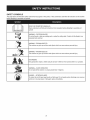 7
7
-
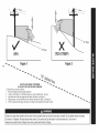 8
8
-
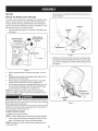 9
9
-
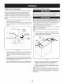 10
10
-
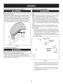 11
11
-
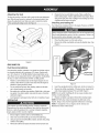 12
12
-
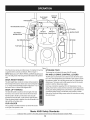 13
13
-
 14
14
-
 15
15
-
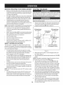 16
16
-
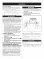 17
17
-
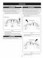 18
18
-
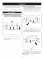 19
19
-
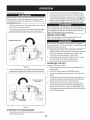 20
20
-
 21
21
-
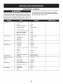 22
22
-
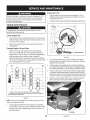 23
23
-
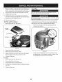 24
24
-
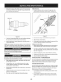 25
25
-
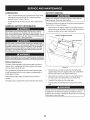 26
26
-
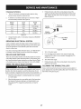 27
27
-
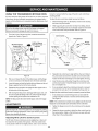 28
28
-
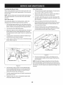 29
29
-
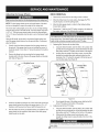 30
30
-
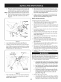 31
31
-
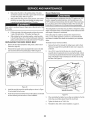 32
32
-
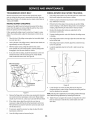 33
33
-
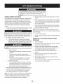 34
34
-
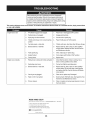 35
35
-
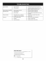 36
36
-
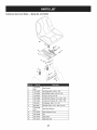 37
37
-
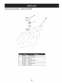 38
38
-
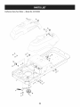 39
39
-
 40
40
-
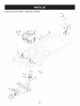 41
41
-
 42
42
-
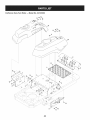 43
43
-
 44
44
-
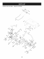 45
45
-
 46
46
-
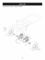 47
47
-
 48
48
-
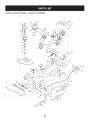 49
49
-
 50
50
-
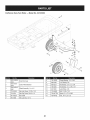 51
51
-
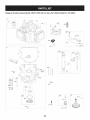 52
52
-
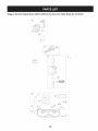 53
53
-
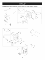 54
54
-
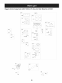 55
55
-
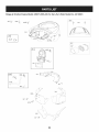 56
56
-
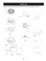 57
57
-
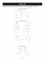 58
58
-
 59
59
-
 60
60
-
 61
61
-
 62
62
-
 63
63
-
 64
64
-
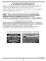 65
65
-
 66
66
-
 67
67
-
 68
68
-
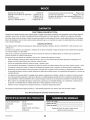 69
69
-
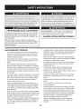 70
70
-
 71
71
-
 72
72
-
 73
73
-
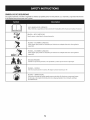 74
74
-
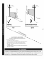 75
75
-
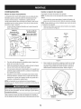 76
76
-
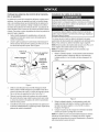 77
77
-
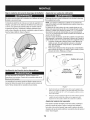 78
78
-
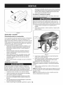 79
79
-
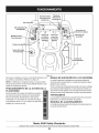 80
80
-
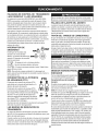 81
81
-
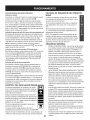 82
82
-
 83
83
-
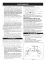 84
84
-
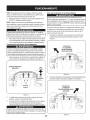 85
85
-
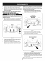 86
86
-
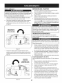 87
87
-
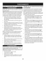 88
88
-
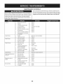 89
89
-
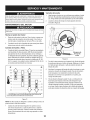 90
90
-
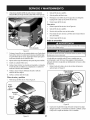 91
91
-
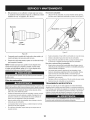 92
92
-
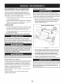 93
93
-
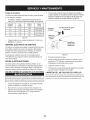 94
94
-
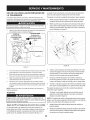 95
95
-
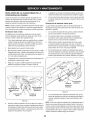 96
96
-
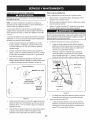 97
97
-
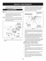 98
98
-
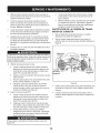 99
99
-
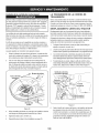 100
100
-
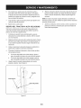 101
101
-
 102
102
-
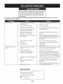 103
103
-
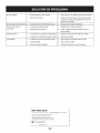 104
104
-
 105
105
-
 106
106
-
 107
107
-
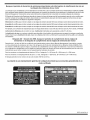 108
108
-
 109
109
-
 110
110
-
 111
111
-
 112
112


Craftsman 17AK2ACP099 El manual del propietario
- Categoría
- Cortadoras de césped
- Tipo
- El manual del propietario
- Este manual también es adecuado para
en otros idiomas
- English: Craftsman 17AK2ACP099 Owner's manual
Artículos relacionados
-
Craftsman 247250030 El manual del propietario
-
-
-
MTD 247.28911 Manual de usuario
-
-
-
Kmart 02876870-3 El manual del propietario
-
-
Craftsman 247.28905 Manual de usuario
-