GE CV48SSL1SS Manual de usuario
- Categoría
- Campanas de cocina
- Tipo
- Manual de usuario

Write the model and serial
numbers here:
Model # _________________
Serial # _________________
You can find them on a label on
the front panel of the unit.
ESPAÑOL
Para consultar una version en
español de este manual de
instrucciones, visite nuestro sitio de
internet GEAppliances.com.
VENT HOOD
Stainless Steel Professional
49-80819 11-17 GEA
SAFETY INFORMATION ...........3
USING THE HOOD
Controls ................................5
Implement Holders .......................5
For your Safety ..........................5
CARE AND CLEANING
Baffle Grease Filters and Drip Trays ........6
Stainless Steel Surfaces. . . . . . . . . . . . . . . . . . . 7
Light Bulbs .............................7
INSTALLATION INSTRUCTIONS ..8
TROUBLESHOOTING TIPS ........20
WARRANTY ........................22
ACCESSORIES .....................23
CONSUMER SUPPORT ............24
CV48S
OWNER’S MANUAL &
INSTALLATION
INSTRUCTIONS
GE is a trademark of the General Electric Company. Manufactured under trademark license.

2 49-80819
THANK YOU FOR MAKING GE APPLIANCES A PART OF YOUR HOME.
Whether you grew up with GE Appliances, or this is your first, we’re happy to have you in the family.
We take pride in the craftsmanship, innovation and design that goes into every GE Appliances
product, and we think you will too. Among other things, registration of your appliance ensures that we
can deliver important product information and warranty details when you need them.
Register your GE appliance now online. Helpful websites and phone numbers are available in the
Consumer Support section of this Owner’s Manual. You may also mail in the pre-printed registration
card included in the packing material.

49-80819 3
SAFETY INFORMATION
READ AND SAVE THESE INSTRUCTIONS
IMPORTANT SAFETY INFORMATION
READ ALL INSTRUCTIONS BEFORE USING
WARNING
TO REDUCE THE RISK OF FIRE,
ELECTRIC SHOCK OR INJURY TO PERSONS,
OBSERVE THE FOLLOWING:
A. Use this unit only in the manner intended by the
manufacturer. If you have questions, contact the
manufacturer.
B. Before servicing or cleaning unit, switch power off
at service panel and lock the service disconnecting
means to prevent power from being switched
on accidentally. When the service disconnecting
means cannot be locked, securely fasten a
prominent warning device, such as a tag, to the
service panel.
C. Do not use this unit with any solid-state speed
control device.
D. This unit must be grounded.
CAUTION
FOR GENERAL VENTILATING USE
ONLY. DO NOT USE TO EXHAUST HAZARDOUS
OR EXPLOSIVE MATERIALS AND VAPORS.
CAUTION
To reduce risk of fire and to properly
exhaust air, be sure to duct air outside. Do not vent
exhaust air into spaces within walls or ceilings or into
attics, crawl spaces, or garages.
WARNING
TO REDUCE THE RISK OF INJURY
TO PERSONS IN THE EVENT OF A RANGE TOP
GREASE FIRE, OBSERVE THE FOLLOWING*:
A. SMOTHER FLAMES with a close-fitting lid, cookie
sheet or metal tray, then turn off the burner. BE
CAREFUL TO PREVENT BURNS. If the flames do
not go out immediately, EVACUATE AND CALL
THE FIRE DEPARTMENT.
B. NEVER PICK UP A FLAMING PAN—You may be
burned.
C. DO NOT USE WATER, including wet dishcloths or
towels—a violent steam explosion will result.
D. Use an extinguisher ONLY if:
1. You know you have a Class ABC extinguisher,
and you already know how to operate it.
2. The fire is small and contained in the area where
it started.
3. The fire department is being called.
4. You can fight the fire with your back to an exit.
* Based on “Kitchen Fire Safety Tips” published by
NFPA.
WARNING
TO REDUCE THE RISK OF A
RANGE TOP GREASE FIRE:
A. Never leave surface units unattended at high
settings. Boil overs cause smoking and greasy
spillovers that may ignite. Heat oils slowly on low or
medium settings.
B. Always turn hood ON when cooking on high heat or
when flambéing food (i.e. Crepes Suzette, Cherries
Jubilee, Peppercorn Beef Flambé).
C. Clean ventilating fans frequently. Grease should not
be allowed to accumulate on fan or filter.
D. Use proper pan size. Always use cookware
appropriate for the size of the surface element.

4 49-80819
SAFETY INFORMATION
IMPORTANT SAFETY INFORMATION
READ ALL INSTRUCTIONS BEFORE USING
READ AND SAVE THESE INSTRUCTIONS
How to Remove Protective Shipping Film and Packaging Tape
Carefully grasp a corner of the protective shipping film
with your fingers and slowly peel it from the appliance
surface. Do not use any sharp items to remove the film.
Remove all of the film before using the appliance for the
first time.
To assure no damage is done to the finish of the
product, the safest way to remove the adhesive from
packaging tape on new appliances is an application of
a household liquid dishwashing detergent. Apply with a
soft cloth and allow to soak.
NOTE: The adhesive must be removed from all parts.
WARNING
TO REDUCE THE RISK OF FIRE,
ELECTRIC SHOCK OR INJURY TO PERSONS,
OBSERVE THE FOLLOWING:
A. Installation work and electrical wiring must be
done by qualified person(s) in accordance with all
applicable codes and standards, including fire-rated
construction.
B. Sufficient air is needed for proper combustion and
exhausting of gases through the flue (chimney) of
fuel burning equipment to prevent back drafting.
Follow the heating equipment manufacturer’s
guidelines and safety standards such as those
published by the National Fire Protection
Association (NFPA), the American Society for
Heating, Refrigeration and Air Conditioning
Engineers (ASHRAE) and the local code authorities.
When applicable, install any makeup (replacement)
air system in accordance with local building code
requirements. Visit GEAppliances.com for available
makeup air solutions.
C. When cutting or drilling into wall or ceiling, do not
damage electrical wiring and other hidden utilities.
D. Ducted fans must always be vented to the outdoors.
E. Turn off breaker to adjacent rooms while working.
WARNING
TO REDUCE THE RISK OF FIRE,
USE ONLY METAL DUCTWORK.
Do not attempt to repair or replace any part of your hood
unless it is specifically recommended in this manual.
All other servicing should be referred to a qualified
technician.

49-80819 5
1. Light control: Turn the light control from OFF
to HI for the brightest light while cooking.
2. Fan control: Turn the fan control speed from
OFF to HI as needed.
Continuous use of the fan system while cooking
helps keep the kitchen comfortable and less humid.
It also reduces cooking odors and soiling moisture
that create a frequent need for cleaning.
NOTE: When the fan is operating on the lowest
setting, it will be very quiet. Always make sure that
the fan is turned OFF when you are finished in the
kitchen.
Controls
USING THE HOOD: Controls / Implement Holders / For your Safety
Appearance will vary.
12
Before servicing or cleaning unit, switch power off at service panel and lock the service disconnecting means to
prevent power from being switched on accidentally. When the service disconnecting means cannot be locked,
securely fasten a prominent warning device, such as a tag, to the service panel.
For your Safety

6 49-80819
Some models have reusable metal grease baffles and
drip trays.
The metal baffles channel grease released by foods
on the cooktop into the drip trays. The baffles also help
prevent flaming foods on the cooktop from damaging the
inside of the hood.
For this reason, the baffles must ALWAYS be in place
when the hood is used. The grease baffles and drip trays
should be cleaned once a month, or as needed.
To clean the grease baffles and drip trays, drain and
wipe all excess grease with a dry paper towel. Soak
them and then swish them around in hot water and
detergent. Don’t use ammonia or ammonia products
because they will darken the metal. Do not use abrasives
or oven cleaners. Rinse, shake and let them dry before
replacing. They may also be cleaned in an automatic
dishwasher.
To remove:
Grasp the baffle knobs and pull them up, forward and
out. Grasp the drip tray and carefully lift it up and out of
the hood track.
To replace the drip trays:
1. Place and seat the drip tray into the hood track.
2. Slide them left or right until all trays are side-by-side
in place in the track.
To replace the baffles:
1. Hold the baffle at the bottom by one of the knobs .
2. Place the other end of the baffle against the inside
front of the hood.
3. Slide it up and push the bottom end back until it firmly
seats into place.
To clean behind the knobs:
If the knobs are difficult to remove, place a non-abrasive
cloth between the knob gap and hood body to assist with
pulling the knobs off for cleaning.
Baffle Grease Filters and Drip Trays (on some models)
CARE AND CLEANING: Baffle Grease Filters and Drip Trays
Drip Tray Replacement
Drip Tray
Drip Tray
Track
Baffle
Baffle Replacement

49-80819 7
Do not use a steel wool pad; it will scratch the surface.
To clean the stainless steel surface, use warm sudsy
water or a stainless steel cleaner or polish. Always wipe
the surface in the direction of the grain. Follow the cleaner
instructions for cleaning the stainless steel surface.
To inquire about purchasing stainless steel appliance
cleaner or polish, or to find the location of a dealer
nearest you, please call our toll-free number:
National Parts Center 1.800.626.2002
GEApplianceParts.com
To change the light bulbs:
1. Grasp the outer trim ring and twist until reaching the
unlock position. Then pull the ring straight out.
2. Grasp the bulb and twist until reaching the unlock
position. Then gently pull the bulb straight out.
3. Replace with the same wattage, type and size bulb.
Wear gloves. Do not touch bulb with your bare
fingers.
These 120 volt, 50 watt halogen bulbs with a GU10
base are available at specialty lighting stores and
home building centers.
Order bulb no. WB08X10052.
4. Replace the outer trim ring by inserting the two
retaining tabs into the two tab slots, pressing the ring
flush with the surface of the hood insert and twisting
until reaching the lock position.
Stainless Steel Surfaces (on some models)
Light Bulbs
CARE AND CLEANING: Stainless Steel Surfaces / Light Bulbs

8 49-80819
Installation
Instructions
“If you have questions, call GE Appliances at 800.GE.CARES (800.432.2737)
or visit our website at: GEAppliances.com”
INSTALLATION INSTRUCTIONS
BEFORE YOU BEGIN
Read these instructions completely and
carefully.
Ŷ
IMPORTANT — Save these
instructions for local inspector’s use.
Ŷ
IMPORTANT — Observe all governing
codes and ordinances.
Ŷ Note to Installer – Be sure to leave these
instructions with the Consumer.
Ŷ Note to Consumer – Keep these instructions for
future reference.
Ŷ Skill level – Installation of this vent hood requires
basic mechanical and electrical skills.
Ŷ Completion time – Approximately 1 to 3 hours
Ŷ 3URSHULQVWDOODWLRQLVWKHUHVSRQVLELOLW\RIWKH
installer.
Ŷ 3URGXFWIDLOXUHGXHWRLPSURSHULQVWDOODWLRQLVQRW
covered under the Warranty.
FOR YOUR SAFETY
WARNING
Before beginning the installation,
switch power off at service panel and lock the
service disconnecting means to prevent power from
being switched on accidentally. When the service
disconnecting means cannot be locked, securely
fasten a prominent warning device, such as a tag,
to the service panel.
CAUTION
Due to the weight and size of
these vent hoods and to reduce the risk of personal
injury or damage to the product, TWO PEOPLE
ARE REQUIRED FOR PROPER INSTALLATION.
WARNING
Disconnect all electrical power
at the main circuit breaker or fuse box before
installing.
Professional Vent Hood
WARNING
TO REDUCE THE RISK OF FIRE,
ELECTRIC SHOCK OR INJURY TO PERSONS,
OBSERVE THE FOLLOWING:
A. Installation work and electrical wiring must be
done by qualified person(s) in accordance with
all applicable codes and standards, including
fire-rated construction.
B. Sufficient air is needed for proper combustion
and exhausting of gases through the flue
(chimney) of fuel burning equipment to prevent
back drafting. Follow the heating equipment
manufacturer’s guidelines and safety standards
such as those published by the National Fire
Protection Association (NFPA), the American
Society for Heating, Refrigeration and Air
Conditioning Engineers (ASHRAE) and the local
code authorities.
C. When cutting or drilling into wall or ceiling, do
not damage electrical wiring and other hidden
utilities.
D. Ducted fans must always be vented to the
outdoors.
E. Turn off breaker to adjacent rooms while
working.
WARNING
TO REDUCE THE RISK OF FIRE,
USE ONLY METAL DUCT WORK.

49-80819 9
PRODUCT DIMENSIONS
Model CV48S With Straight Sides
HARDWARE PACKAGE
Locate and check contents.
Screws shown actual size.
PARTS PROVIDED
Locate the parts packed with the hood.
INSTALLATION PREPARATION
2 Knobs
2 Stainless Steel Grease Filters
(3 filters with 48" models)
Wood Support
with Original Screws
2 Grease Filter Trays
(3 supports with 48" models.)
2 (3/16") hollow wall anchors
with screws to secure hood to
the wall at the bottom
2 flat washers for
wall anchors
6 Phillips head screws
to secure hood to
the wood support:
(2 secured to wood
support)
6 screws to secure the wood
support and the hood to the wall
Installation Preparation
12"
47 15/16"
47 15/16"25"
18"

10 49-80819
INSTALLATION PREPARATION
Installation Preparation
TOOLS AND MATERIALS
REQUIRED
(NOT SUPPLIED)
CAUTION
Lift the hood by grasping the
outside edges of the inlet opening of the hood. Do
not lift the hood by grasping the exhaust opening or
transition duct with damper!
Ŷ 2SHQWKHFDUWRQDQGUHPRYHWKHKRRGDQG
packaging.
Ŷ &RQILUPWKDWDOOKDUGZDUHDQGSDUWVDUHSUHVHQW
by reviewing the section named Parts Provided in
the Installation Instructions.
Ŷ /RRVHQWKHVFUHZVKROGLQJWKHZRRGVXSSRUWWR
the back of the hood. Remove wood support.
Keep wood support and screws. These will be
used to mount the hood to the wall.
Ŷ )XOO\LQVSHFWDQGFRQILUPWKDWDOOWDSHDQG
packing material has been removed from the
hood and transition duct with damper
Pliers
Wire Cutter/Stripper
Tin Snips
Spirit level
Duct tape
Safety glasses
Ladder
Saber saw or Key Hole Saw
Phillips and Flat blade
screwdrivers
1/4” pivoting hex socket
Hammer
Electric drill with 1/8” and 3/8” bits
Flashlight
UL Listed Wire nuts
Pencil and tape
measure
120V 60Hz. 15 or 20 Amp,
2-wire with ground. Properly
grounded branch circuit.
Strain relief for
junction cover.
10" round metal duct,
length to suit installation
Top view of open shipping carton
Do not lift from
transition duct Hood
Lift hood out of carton
from the sides
Carton

49-80819 11
Installation Preparation
INSTALLATION PREPARATION
INSTALLATION CLEARANCES
These vent hoods are designed to be installed onto
a wall or beneath a soffit or cabinet.
Ŷ ,QVWDOOWKHVHKRRGV0LQWR0D[DERYH
the cooking surface.
NOTE: Clearances may vary due to type of
cooking product and local codes. Check with
local inspectors to be sure standard is applicable.
In this installation the ductwork running from the top
of the hood will be concealed in the soffit or upper
cabinetry.
For this installation, a decorative duct cover is
available to conceal the ductwork running from the
top of the hood. Use of the duct cover requires
special consideration to the installation height
above the countertop.
OPTIONAL DUCT COVER
ACCESSORIES
Standard decorative duct covers are available in
6" and 12" heights. Duct covers may be stacked,
in various combinations, to conceal the ductwork
running from the top of the hood to the ceiling.
Ŷ %HIRUH\RXEHJLQ\RXVKRXOGGHWHUPLQHWKH
installation height of the hood and order the
correct size duct cover. The duct covers should
be ordered at the same time as the vent hood
and be on site before installation. Order the duct
cover corresponding to your model.
6” Duct Covers
Hood
Model
6” Duct
Cover Dimensions
CV48S UX48DC6J 6”H x 19-11/16”W x 11-7/8”D
12” Duct Covers
Hood
Model
12” Duct
Cover Dimensions
CV48S UX48DC12J 12”H x 19-11/16”W x 11-7/8”D
OPTIONAL SERVICE PART
RANGE HOOD UTENSIL HOLDER
A utensil rack part # WB02X25909 is available as a
service part for this hood.
Visit GEApplianceParts.com for more details.
Wall Mount Installation
30" MIN.
36" MAX.
SOFFIT
Soffit Installation
30" MIN.
36" MAX.
6" Duct Cover
12" Duct Cover
Standard Duct Covers

12 49-80819
DETERMINE INSTALLATION HEIGHT, DUCT COVER ACCESSORIES
These vent hoods must be installed 30” min. to 36”
max. above the standard 36” high cooking surface
when installed over any professional style rangetop or
range. The exact hood installation height is determined
by the ceiling height.
1. Measure the exact ceiling height.
2. Review the chart at right to determine the range
of possible hood installation heights that can be
accomplished with one or more duct covers.
3. Increase or decrease hood installation height to
accommodate the fixed 6" or 12" duct covers and
use a whole number of duct covers, otherwise cutting
and modifying one duct cover may be required.
4. Duct covers may be stacked, in various
combinations, to reach ceiling heights.
Straight or Taper-Sided Hoods
NOTE: Minimum ceiling height for REAR WALL
EXHAUST with duct covers is 8'4" when installing at
30" above countertop using 10" elbow.
*Based on 36" countertop height.
NOTE: Additional duct covers may be used to reach
higher ceilings.
INSTALLATION PREPARATION
Installation Preparation
Actual
Ceiling
Height
*Possible
Hood
Installation
Height
6" Duct
Covers
12" Duct
Covers
7' 11" 35" 1
8' 0"
8' 0"
30"
36" 1
1
8' 1" 31" 1
8' 2" 32" 1
8' 4" 33" 1
8' 4" 34" 1
8' 5" 35" 1
8' 6"
8' 6"
30"
36"
11
1
8' 7" 31" 1 1
8' 8" 32" 1 1
8' 9" 33" 1 1
8' 10" 34" 1 1
8' 11" 35" 1 1
9' 0"
9' 0"
30"
36" 1
2
1
9' 1" 31" 2
9' 2" 32" 2
9' 3" 33" 2
9' 4" 34" 2
9' 5" 35" 2
9' 6"
9' 6"
30"
36" 1
2
1
9' 7" 31" 1 2
9' 8" 32" 1 2
9' 9" 33" 1 2
9' 10" 34" 1 2
9' 11" 35" 1 2
10' 0"
10' 0"
30"
36" 1
3
2
10' 1" 31" 3
10' 2" 32" 3
10' 3" 33" 3
10' 4" 34" 3
Installation Height
Ceiling Height
to Floor
Duct Covers
18" Hood
Height

49-80819 13
Installation Preparation
INSTALLATION PREPARATION
ADVANCE PLANNING
Duct Install Planning
Ŷ 7KHVHYHQWKRRGVDUHHTXLSSHGIRU´URXQG
ductwork. For best performance, use 10” round
ductwork on the 48” wide hoods.
Ŷ 7KLVKRRGPD\EHYHQWHGYHUWLFDOO\WKURXJKXSSHU
cabinets, soffit or ceiling. A duct transition piece is
supplied for vertical exhaust. Use locally supplied
elbows to vent horizontally through the rear wall.
Ŷ 8VHPHWDOGXFWZRUNRQO\
Ŷ 'HWHUPLQHWKHH[DFWORFDWLRQRIWKHYHQWKRRG
Ŷ 3ODQWKHURXWHIRUYHQWLQJH[KDXVWWRWKH
outdoors. To maximize the ventilation
performance of the vent system:
1. Minimize the duct run length and number of
transitions and elbows.
2. Maintain a constant duct size.
3. Seal all joints with duct tape to prevent any
leaks.
4. Do not use any type of flexible ducting.
Ŷ 8VHWKHVKRUWHVWDQGVWUDLJKWHVWGXFWURXWH
possible.
Ŷ ,QVWDOODZDOOFDSRUURRIFDSZLWKGDPSHUDWWKH
exterior opening. Order the wall or roof cap and
any transition needed in advance.
Ŷ :KHQDSSOLFDEOHLQVWDOODQ\PDNHXS
(replacement) air system in accordance
with local building code requirements. Visit
GEAppliances.com for available makeup air
solutions.
Wall Framing for Adequate Support
Ŷ 7KLVYHQWKRRGLVKHDY\$GHTXDWHVWUXFWXUDO
support must be provided. The hood must be
secured to vertical studs in the wall. See page 14.
Ŷ :HVWURQJO\UHFRPPHQGWKDWWKHYHQWKRRGZLWK
duct cover be on site before final framing and
wall finishing. This will also help to accurately
locate the ductwork and electrical service.
Decorative Duct Covers:
Decorative duct covers, 6" and 12" high, are
available to fit all models. The duct cover conceals
the ductwork running from the top of the hood to the
ceiling or soffit. Stack one or more duct covers over
the top of the hood to reach your ceiling height.
POWER SUPPLY
IMPORTANT – (Please read carefully)
WARNING
FOR PERSONAL SAFETY, THIS APPLIANCE
MUST BE PROPERLY GROUNDED.
Remove house fuse or open circuit breaker before
beginning installation.
Do not use an extension cord or adapter plug with
this appliance. Follow National Electrical Codes or
prevailing local codes and ordinances.
Electrical supply
These vent hoods must be supplied with 120V,
60Hz, and connected to an individual, properly
grounded branch circuit, and protected by a 15 or
20 amp circuit breaker or time delay fuse.
Ŷ :LULQJPXVWEHZLUHZLWKJURXQG
Ŷ ,IWKHHOHFWULFDOVXSSO\GRHVQRWPHHWWKHDERYH
requirements, call a licensed electrician before
proceeding.
Ŷ 5RXWHKRXVHZLULQJDVFORVHWRWKHLQVWDOODWLRQ
location as possible in the ceiling or wall.
Ŷ &RQQHFWWKHZLULQJWRWKHKRXVHZLULQJLQ
accordance with local codes.
Grounding instructions
The grounding conductor must be connected to
a ground metal, permanent wiring system, or an
equipment-grounding terminal or lead on the hood.
WARNING
The improper connection of the
equipment-grounding conductor can result in a risk
of electric shock. Check with a qualified electrician
or service representative if you are in doubt whether
the appliance is properly grounded.

14 49-80819
INSTALLATION PREPARATION
Installation Instructions
1
DETERMINE HOOD, DUCTWORK AND WIRING LOCATIONS
Ŷ 8VHDOHYHOWRGUDZWKHFRRNWRSFHQWHUOLQHORFDWLRQ
Draw the line to ceiling height.
Ŷ 0HDVXUHGHVLUHGGLVWDQFHIURPWKHERWWRPRIWKH
hood to the cooking surface, 30" min. to 36" max.
NOTE: If you are installing the hood with duct covers,
be sure to read “Using Duct Cover Accessories” page
7. Exact installation height may be determined by use
of one or more duct covers.
Ŷ 8VHDOHYHOWRGUDZDVWUDLJKWKRUL]RQWDOSHQFLOOLQH
indicating the bottom of the hood.
Ŷ )URPWKHOLQHLQGLFDWLQJWKHERWWRPRIWKHKRRG
measure 15-3/8" up and draw another line for the
location of the wood support. See illustration.
FOR VERTICAL (Straight Up) DUCTING:
Ŷ 8VHDOHYHOWRGUDZDFHQWHUOLQHIURPWKHERWWRPRI
the hood to ceiling or soffit.
Ŷ ,IYHQWLQJRXWWKHFHLOLQJH[WHQGWKHFHQWHUOLQH
forward on the ceiling or soffit.
Ŷ /RFDWHWKHFHQWHUOLQHRIDKROHRQWKHFHLOLQJ
or soffit by measuring 6" from the wall.
FOR DUCTING THROUGH REAR WALL:
Ŷ 0HDVXUHDERYHWKHPDUNHGOLQHIRUWKHWRS
of the hood. At the centerline, mark location for a
10-1/2" diameter hole.
NOTE: Minimun ceiling height for REAR WALL
EXHAUST with duct covers is 8'4" when installing at
30" above countertop using 10" elbow
House Wiring Location:
Ŷ 7KHMXQFWLRQER[LVIDVWHQHGWRWKHEDFNRIWKHKRRG
on the right side.
Ŷ 7KHUHFHVVHGEDFNVLGHRIWKHKRRGSURYLGHVD
large area for the house wiring to exit the wall and
be routed to the rear knockout and junction box.
Ŷ 5HPRYHMXQFWLRQER[FRYHUDQGNQRFNRXW,QVWDOO
strain relief.
Alternate Knockout Locations
If the installation requires, the junction box can
be relocated from the back to the top of the hood.
Remove 3 screws, align box to top knockout and
secure with original screws.
Ŷ 5HPRYHMXQFWLRQER[FRYHUDQGNQRFNRXW,QVWDOO
strain relief.
18-13/16" for 48" Models
12-13/16" for 36" Models
9-13/16" for 30" Models
Electrical
Area
8-3/8"
6-1/2"
18-1/16" for 48" Models
12-1/16" for 36" Models
9-1/16" for 30" Models
Bottom of Hood
Wood
Support
Top of Hood
15-3/8"
18"
9-7/8"

49-80819 15
Installation Instructions
INSTALLATION PREPARATION
2A
INSTALL HOOD ONTO WALL
SKIP THIS STEP IF INSTALLING BENEATH A
SOFFIT OR CABINET, GO TO STEP 2B.
Ŷ /RFDWHDWOHDVWYHUWLFDOVWXGVDWWKHZRRGVXSSRUW
Ŷ )RU´PRGHOVLIYHUWLFDOVWXGVFDQQRWEHORFDWHG
then install 2 screws through the wood support into
the stud that is located, vertically aligned with the
screws located ½” from the edge of the wood support.
Ŷ &HQWHUWKHVXSSOLHGZRRGVXSSRUWOHIWWRULJKWDQG
below the 15-3/8" marked line.
Ŷ 6HFXUHWKHZRRGVXSSRUWWRRUPRUHYHUWLFDOVWXGV
using at least 2 of the 4 supplied long screws. For the
30” model, you may need to add framing to existing
framing to secure the wood support to 2 studs.
IMPORTANT: Screws must penetrate at least 1” into
vertical studs. Countersink screws into support.
NOTE: The mounting screws
must remain in their original
shipping location. These
screws are positioned
to engage the
keyhole slots in
the back of the
hood.
Ŷ Adjust depth of original mounting screws in the
wood support until they protrude 1/4" forward. This
1/4" gap will provide clearance to hang the hood.
IMPORTANT: Framing must be capable of
supporting up to 150 lbs.
Ŷ 8VHGXFWWDSHWRVHDOWKHWUDQVLWLRQGXFWFRQQHFWLRQ
Check to be sure the damper moves freely.
Hang Hood On Wood Support
Ŷ /LIWWKHKRRGDQGKROGFORVHWRWKHLQVWDOODWLRQ
location. Route house wiring through the knockout
and into the junction box.
Ŷ 3ODFHWKHKRRGRYHUWKHZRRGVXSSRUW%HVXUHWKH
mounting screws engage the keyhole slots in the
back of the hood. Tighten the screws.
Ŷ ,QVWDOODGGLWLRQDOVFUHZVWRVHFXUHWKHKRRGWRWKH
wood support.
Ŷ 'ULOO´SLORWKROHVLQWRWKHWZRORZHUKROHV,IWKH
pilot hole enters a stud, use a washer and the long
wood screw. If the pilot hole does not enter a stud,
enlarge the hole to 3/8” to accept the wall anchor, and
use a washer and the screw from the wall anchor.
Centerline of
Installation
Space
15-3/8"
30"
to
36"
Wood
Support
1/4"
Gap
Original Mounting
Screws as Shipped
Centerline of
Installation
Space
30"
to
36"

16 49-80819
INSTALLATION PREPARATION
Installation Instructions
2B
Alternate Mounting Method
INSTALL HOOD TO SOFFIT OR BENEATH CABINETS
SKIP THIS STEP IF USING WALL MOUNTING
METHOD
When necessary, the hood may be installed so that it
is supported by the soffit.
Ŷ 7KHVRIILWVKRXOGEHFRQVWUXFWHGZLWK[¶V
Ŷ 'HWHUPLQHWKHLQVWDOODWLRQORFDWLRQRQWKHZDOO
Ŷ &RQWLQXHWKHFHQWHUOLQHIRUZDUGRQWKHERWWRPRIWKH
cabinet or soffit.
Ŷ 7KHRSHQLQJDERYHWKHKRRGVKRXOGDOORZIRUWKH
10" round duct and clearance to slide the hood back
against the wall.
Ŷ 7KH[VWXGVPXVWEHORFDWHGDVVKRZQLQWKH
chart, Dim. A. to accept mounting screws.
“A” Centerline to Stud
and Keyhole Slots
“B” Hood Width At
the Top
CV48S 23-9/16" 47-15/16"
Ŷ 'ULOOSLORWKROHVLQWRWKHVWXGVDWWKHORFDWLRQV
shown in the top view illustration.
IMPORTANT: Soffit framing must be capable of
supporting up to 150 lbs.
Ŷ 8VHGXFWWDSHWRVHDOWKHWUDQVLWLRQGXFWFRQQHFWLRQ
Check to be sure the damper moves freely.
Mount Hood onto Soffit or Cabinet
NOTE: If mounting to the underside of a cabinet with a
recessed bottom, install shims to fill the gap.
Ŷ 'ULYHPRXQWLQJVFUHZVLQWRWKHVWXGVXQWLOWKH\
protrude 1/4". The 1/4" gap will provide clearance to
engage the keyhole slots in the top of the hood.
Ŷ /LIWKRRGWRLQVWDOODWLRQSRVLWLRQ/RFDWHKRXVHZLULQJ
and route through the knockout (from the back or
top of the hood).
Ŷ /LIWKRRGRQWRPRXQWLQJVFUHZV6OLGHEDFNDJDLQVW
the rear wall.
Ŷ 7LJKWHQPRXQWLQJVFUHZV
IMPORTANT: For additional support and to
minimize vibration during operation, the hood must
be secured to the back wall. Use wall anchors to
fasten bottom back of hood to the wall.
A
Requires 10-1/2" Min.
Opening For Ductwork
and Hood Installation
A
2"
7-1/2"
A
B
2-9/16"
10"
3/4"
Back of Hood
Top View
Front of Hood
1/4" Gap
Push Back
to Wall
Add Shims
If Bottom
Is Recessed
Back
Wall
Cabinet
or
Soffit
Engage Top
Keyhole Slots

49-80819 17
Installation Instructions
INSTALLATION PREPARATION
3
CONNECT DUCTWORK
Ŷ ,QVWDOOGXFWZRUNPDNLQJFRQQHFWLRQVLQGLUHFWLRQ
of airflow as illustrated.
Ŷ 6HFXUHMRLQWVLQGXFWZRUNZLWKVKHHWPHWDOVFUHZV
Ŷ :UDSDOOGXFWMRLQWVZLWKGXFWWDSHIRUDQDLUWLJKW
seal.
Ŷ 8VHGXFWWDSHWRVHDOWKHIODQJHFRQQHFWLRQ
Reach inside the hood and push the damper up
to be sure it moves freely.
5
INSTALL DUCT COVERS
NOTE: For easier handling, remove cardboard
insert after film is peeled off.
Remove protective film from duct covers. If more
than one duct cover is used, secure each piece
together with screws provided.
Ŷ 3ODFHWKHGXFWFRYHUVRQWRSRIWKHKRRG
Ŷ )URPLQVLGHWKHKRRGVHFXUHWKHGXFWFRYHU
to the top with the small Phillips head screws
supplied with the covers.
4
CONNECT ELECTRICAL
Verify that power is turned off at the source.
WARNING
If house wiring is not 2-wire with
a ground wire, a ground must be provided by the
installer. When house wiring is aluminum, be sure
to use U.L. approved anti-oxidant compound and
aluminum-to-copper connectors.
Ŷ 8VHZLUHQXWVWRFRQQHFWLQFRPLQJJURXQGWR
green, white to white and black to black.
Ŷ 3XVKZLUHVLQWRMXQFWLRQER[DQGUHSODFHFRYHU
Be sure wires are not pinched.
Screw
Duct Tape
Over Seam
and Screw
Air Flow
Duct Tape
Over Transition
White
Ground
Black
Remove
Junction Box
Cover
A.
Insert Power
Conduit Thru
Strain Relief
and Tighten
B.
Use UL Listed
Wire Nuts
C.

18 49-80819
INSTALLATION PREPARATION
Installation Instructions
6
INSTALL FILTERS
Ŷ 3ODFHILOWHUGULSWUD\VLQWRWKHUHDURIWKHKRRG
Ŷ ,QVHUWWKHJUHDVHILOWHULQWRWKHRSHQLQJDQGGURS
into the trays.
Ŷ 7RUHPRYHWKHILOWHUVJUDVSWKHKDQGOHSXVKWKH
filter up and lift out.

49-80819 19
Notes

20 49-80819
Troubleshooting tips ... Before you call for service
TROUBLESHOOTING TIPS
Save time and money! Review the charts on the following pages first and you may not need to call for service.
Problem Possible Cause
Fan and lights do
not operate when the
switches are turned on
Ŷ The hood was never electrically connected by the installer/ electrician/builder. Call the
electrician/installer/builder to complete the installation. This is not covered by warranty.
Ŷ A fuse may be blown or a circuit breaker tripped. Replace the fuse or reset the circuit breaker.
The blower does not
work but the lights do
Ŷ The blower motor wire harness was not connected or was not connected properly by the
installer/electrician/builder to its mating connector located inside the hood on the top surface, to
the left of the blower assembly.
1. Switch power off at service panel and lock the service disconnecting means to prevent power
from being switched on accidentally. When the service disconnecting means cannot be
locked, securely fasten a prominent warning device, such as a tag, to the service panel.
2. Remove the filters and locate the blower wire harness connector. Is it plugged into its mating
connector?
3. If no, plug the blower motor connector into its mating connector on the top of the hood. Switch
the power back on. Check to see if the fan now works.
4. If no, check the circuit breaker/fuse. If it is blown/tripped, replace/reset it. Does the blower
work now? If no, call GE Appliances for service.
The blower fails to
exhaust the smoke/
steam/ odors adequately
Ŷ Many factors could be the root cause for reduced air-flow.
1. Installation could be the problem: Your hood was designed to meet specific ducting
requirements. If your duct length exceeds the manufacturer’s requirements, hood performance
will suffer. Air-flow will also be reduced if the house duct work is too small or there are too
many elbows in the system. Contact your installer or builder.
2. Obstruction in duct work could be the problem: Make sure nothing is blocking the vent (bird
nests or kinks in the duct work).
3. Damper blade may not be opening: Make sure the tape is removed from the damper blades
and that it swings open freely.
4. Damper blade on Wall or Roof Cap may not be opening: Contact your builder so they can
make sure the damper swings open freely.
5. Dirty filters/baffles: Make sure filters (and all hood surfaces) are kept clean of grease and dirt.
6. Check to be sure the filter is clean: If replacing the filter does not correct the problem, call for
service.
7. Sufficient makeup (replacement) air is required for exhausting appliances to operate to rating.
Check with local building codes, which may require or strongly advise the use of makeup air.
Visit GEAppliances.com for available makeup air solutions.

49-80819 21
Troubleshooting tips ... Before you call for service
TROUBLESHOOTING TIPS
Problem Possible Cause
The halogen does not
work
Ŷ The lamp or socket may be defective or a wire could be disconnected.
1. Do some trouble-shooting by removing the lamp and place it in the socket of a lamp that
does work. Does it work now? If no, the lamp is defective. If your hood is still in-warranty,
call GE Appliances service and ask them to mail out a new lamp. Lamps on this product
are covered by warranty and are cataloged. If the hood is no longer covered by warranty,
reference the Care and Cleaning section of this manual to see lamp requirements. Lamps
can be purchased at home building stores, specialty lighting stores or through GE Appliances
Parts. Reference the defective lamp for information as well.
2. If you placed the lamp in a working socket and it does illuminate, the original socket may be
defective or a wire may be disconnected. Call GE Appliances for service.
Part is missing/
damaged/defective
Ŷ In the unlikely event that a part would be missing, damaged or defective, we can serve you, the
consumer, quickly by mailing these parts to you. We have identified several easy-to-install parts.
These include:
Lamps, lamp bezels, filters, baffles, grease trays, knobs, Owner’s Manual and Installation Instructions.
Call GE Appliances service and carefully describe your model number and the part you need.
The model number is located inside the hood chassis, behind the filter/baffle.
Duct cover is missing Ŷ The duct cover is not included with the hood. It must be purchased as an accessory.
– 6" duct cover for use with a 48" hood–order kit #UX48DC6J
– 12" duct cover that works with a 48" hood–order kit #UX48DC12J
Call GE Appliances Parts. See Consumer Service page in this manual for a list of phone numbers.
Installation part is
missing/damaged/
defective
We provide a 10" round, vertical duct transition. This part can be mailed out to the hood installer if
it is in some way unusable. All other duct transitions, elbows, etc must be purchased locally. We
can also mail out many other parts that come with the hood to your installer. Call GE Appliances
Service. See Consumer Service page in this manual for a list of phone numbers. Ask them to mail
the parts only—no service call required.

22 49-80819
Staple your receipt here. Proof of the original purchase
date is needed to obtain service under the warranty.
GEAppliances.com
All warranty service is provided by our Factory Service Centers, or an authorized Customer Care
®
technician. To schedule
service online, visit us at www.geappliances.com/service_and_support/, or call GE Appliances at 800.GE.CARES
(800.432.2737). Please have your serial number and your model number available when calling for service.
Servicing your appliance may require the use of the onboard data port for diagnostics. This gives a GE Appliances factory
service technician the ability to quickly diagnose any issues with your appliance and helps GE Appliances improve its
products by providing GE Appliances with information on your appliance. If you do not want your appliance data to be
sent to GE Appliances, please advise your technician not to submit the data to GE Appliances at the time of service.
What GE Appliances will not cover:
Ŷ Service trips to your home to teach you how to use
the product.
Ŷ Improper installation, delivery, or maintenance.
Ŷ Failure of the product if it is abused, misused,
modified, or used for other than the intended purpose
or used commercially.
Ŷ Replacement of house fuses or resetting of circuit
breakers.
Ŷ Damage to the product caused by accident, fire,
floods, or acts of God.
Ŷ Damage to finish, such as surface rust, tarnish, or small
blemishes not reported within 48 hours of delivery.
Ŷ Incidental or consequential damage caused by
possible defects with this appliance.
Ŷ Damage caused after delivery.
Ŷ Product not accessible to provide required service.
Ŷ Service to repair or replace light bulbs, except for LED
lamps.
WARRANTY
GE Appliances Vented Range Hood Warranty
EXCLUSION OF IMPLIED WARRANTIES
Your sole and exclusive remedy is product repair as provided in this Limited Warranty. Any implied warranties,
including the implied warranties of merchantability or fitness for a particular purpose, are limited to one year or
the shortest period allowed by law.
This warranty is extended to the original purchaser and any succeeding owner for products purchased for home use
within the USA. If the product is located in an area where service by a GE Appliances Authorized Servicer is not available,
you may be responsible for a trip charge or you may be required to bring the product to an Authorized GE Appliances
Service location for service. In Alaska, the warranty excludes the cost of shipping or service calls to your home.
Some states do not allow the exclusion or limitation of incidental or consequential damages. This warranty gives you
specific legal rights, and you may also have other rights which vary from state to state. To know what your legal rights
are, consult your local or state consumer affairs office or your state’s Attorney General.
Warrantor: GE Appliances, a Haier company
Extended Warranties: Purchase a GE Appliances extended warranty and learn about special discounts that are
available while your warranty is still in effect. You can purchase it online anytime at
www.geappliances.com/service_and_support/shop-for-extended-service-plans.htm
or call 800.626.2224 during normal business hours. GE Appliances Service will still be there after your warranty expires.
For the period of GE Appliances will replace
One year
From the date
of the original
purchase
Any part of the cooking product which fails due to a defect in materials or workmanship.
During this limited one-year warranty, GE Appliances will provide, free of charge, all labor
and related service costs to replace the defective part.

49-80819 23
ACCESSORIES
Looking For Something More?
GE Appliances offers a variety of accessories to
improve your cooking and maintenance experiences!
Refer to the Consumer Support page for phone numbers
and website information.
The following products and more are available:
Accessories
Parts
Baffle
Drip Tray
Accessories
Halogen Lamp
Cleaning Supplies
CitruShine™ Stainless Steel Wipes
CERAMA BRYTE
®
Stainless Steel Appliance Cleaner

24 49-80819
Consumer Support
CONSUMER SUPPORT
GE Appliances Website
Have a question or need assistance with your appliance? Try the GE Appliances Website 24 hours a day, any day
of the year! You can also shop for more great GE Appliances products and take advantage of all our on-line support
services designed for your convenience. In the US: GEAppliances.com
Register Your Appliance
Register your new appliance on-line at your convenience! Timely product registration will allow for enhanced
communication and prompt service under the terms of your warranty, should the need arise. You may also mail in
the pre-printed registration card included in the packing material. In the US: GEAppliances.com/register
Schedule Service
Expert GE Appliances repair service is only one step away from your door. Get on-line and schedule your service at
your convenience any day of the year. In the US: GEAppliances.com/ge/service-and-support/service.htm
or call 800.432.2737 during normal business hours.
Extended Warranties
Purchase a GE Appliances extended warranty and learn about special discounts that are available while your
warranty is still in effect. You can purchase it on-line anytime. GE Appliances Services will still be there after your
warranty expires. In the US: GEAppliances.com/ge/service-and-support/shop-for-extended-service-plans.htm
or call 800.626.2224 during normal business hours.
Remote Connectivity
For assistance with wireless network connectivity (for models with remote enable),
visit our website at GEAppliances.com/ge/connected-appliances/ or call 800.220.6899 in the US.
Parts and Accessories
Individuals qualified to service their own appliances can have parts or accessories sent directly to their homes
(VISA, MasterCard and Discover cards are accepted). Order on-line today 24 hours every day.
In the US: GEApplianceparts.com or by phone at 877.959.8688 during normal business hours.
Instructions contained in this manual cover procedures to be performed by any user. Other servicing
generally should be referred to qualified service personnel. Caution must be exercised, since improper
servicing may cause unsafe operation.
Contact Us
If you are not satisfied with the service you receive from GE Appliances, contact us on our Website with all the
details including your phone number, or write to:
In the US: General Manager, Customer Relations | GE Appliances, Appliance Park | Louisville, KY 40225
GEAppliances.com/ge/service-and-support/contact.htm
Printed in Italy

Escriba los números de modelo y
de serie aquí:
Nº de Modelo ____________
Nº de Serie ______________
Los puede encontrar en una etiqueta
sobre el panel frontal de la unidad.
CAMPANA DE VENTILACIÓN
Profesional de Acero Inoxidable
49-80819 11-17 GEA
INFORMACIÓN DE SEGURIDAD ....3
USO DE LA PLACA DE COCCIÓN
Controles .................................5
Barrales ..................................5
Para su Seguridad .........................5
CUIDADO Y LIMPIEZA
Filtros Deflectores de Grasa y
Bandejas de Goteo .......................6
Superficies de Acero Inoxidable .............7
Lámparas de Luz ..........................7
INSTRUCCIONES
DE INSTALACIÓN ..................8
CONSEJOS PARA LA SOLUCIÓN
DE PROBLEMAS ...................20
GARANTÍA ...........................22
ACCESORIOS ........................23
SOPORTE PARA
EL CONSUMIDOR ..................24
GE es una marca registrada de General Electric Company. Fabricado bajo licencia de marca.
CV48S
MANUAL DEL
PROPIETARIO E
INSTALACIÓN

2 49-80819
GRACIAS POR HACER QUE GE APPLIANCES SEA PARTE DE SU HOGAR.
Ya sea que haya crecido usando GE Appliances, o que ésta es su primera vez, nos complace
tenerlo en la familia.
Sentimos orgullo por el nivel de arte, innovación y diseño de cada uno de los electrodomésticos de
GE Appliances, y creemos que usted también. Entre otras cosas, el registro de su electrodoméstico
asegura que podamos entregarle información importante del producto y detalles de la garantía
cuando los necesite.
Registre su electrodoméstico GE ahora a través de Internet. Sitios Web y números telefónicos útiles
están disponibles en la sección de Soporte para el Consumidor de este Manual del Propietario.
También puede enviar una carta en la tarjeta de inscripción preimpresa que se incluye con
el material embalado.

49-80819 3
INFORMACIÓN DE SEGURIDAD
INFORMACIÓN IMPORTANTE DE SEGURIDAD
LEA TODAS LAS INSTRUCCIONES ANTES DE USAR
ADVERTENCIA
PARA REDUCIR EL RIESGO
DE INCENDIO, DESCARGA ELÉCTRICA O LESIONES A
PERSONAS, CUMPLA CON LOS SIGUIENTES PUNTOS:
A. Utilice esta unidad sólo de la manera concebida por el
fabricante. Si tiene alguna pregunta, comuníquese con el
fabricante.
B. Antes de realizar reparaciones o limpiar la unidad,
desconecte la energía del panel de servicio y bloquee los
medios de desconexión para evitar el accionamiento de
la energía de manera accidental. Cuando los medios de
desconexión de servicio no pueden bloquearse, coloque
sobre el panel de servicio un dispositivo de advertencia
bien visible, como una etiqueta.
C. No utilice esta unidad con ningún dispositivo de control
de velocidad de estado sólido.
D. Esta unidad debe estar conectada a tierra.
PRECAUCIÓN
SÓLO PARA USO DE
VENTILACIÓN GENERAL. NO LO UTILICE PARA ELIMINAR
MATERIALES Y VAPORES PELIGROSOS O EXPLOSIVOS.
PRECAUCIÓN
A fin de reducir riesgos de
incendios y para que el aire salga de forma apropiada,
asegúrese de que el aire sea conducido hacia fuera. No
ventile el aire de la salida hacia espacios dentro de paredes
o cielorrasos o áticos, espacios muy bajos o garajes.
ADVERTENCIA
PARA REDUCIR EL RIESGO DE
LESIONES A PERSONAS EN CASO DE UN INCENDIO
DE GRASA SOBRE UNA ESTUFA, CUMPLA CON LOS
SIGUIENTES PUNTOS*:
A. APAGUE LAS LLAMAS con una tapa que ajuste bien,
una plancha para galletas o una bandeja de metal, y
luego apague el quemador. TENGA MUCHO CUIDADO
A FIN DE EVITAR QUEMADURAS. Si las llamas no
se apagan de inmediato, SALGA DE LA VIVIENDA Y
LLAME AL DEPARTAMENTO DE BOMBEROS.
B. NUNCA LEVANTE UNA SARTÉN EN LLAMAS—
Usted puede quemarse.
C. NO UTILICE AGUA, incluyendo repasadores o toallas
húmedos—se provocará una violenta explosión de vapor.
D. Utilice un extintor SÓLO si:
1. Usted sabe que cuenta con un extintor Clase ABC y
ya sabe cómo utilizarlo.
2. El incendio es pequeño y se contuvo en el área donde
comenzó.
3. Se está llamando al departamento de bomberos.
4. Usted puede combatir el incendio con su espalda
dirigida hacia una salida.
* Basado en “Kitchen Fire Safety” publicado por NFPA.
ADVERTENCIA
A FIN DE REDUCIR EL RIESGO
DE INCENDIO DE GRASA SOBRE LA SUPERFICIE DE
UNA COCINA:
A. Nunca descuide las unidades cuando se encuentren a altas
temperaturas. Los hervores excesivos causan vapores y
derrames de grasa que se pueden encender. Caliente los
aceites de forma lenta en las posiciones baja o media.
B. Siempre ENCIENDA la campana al cocinar con fuego alto o
al flambear comidas (tales como: Crepes Suzette, Cerezas
Jubileo, Filetes Flambeados con Granos de Pimienta).
C. Limpie las ventilaciones de forma frecuente. No se debe
permitir la acumulación de grasa en el ventilador o el filtro.
D. Use cacerolas de tamaño apropiado. Siempre utilice
utensilios adecuados al tamaño del elemento sobre la
superficie.
LEA Y GUARDE ESTAS INSTRUCCIONES

4 49-80819
INFORMACIÓN DE SEGURIDAD
LEA Y GUARDE ESTAS INSTRUCCIONES
INFORMACIÓN IMPORTANTE DE SEGURIDAD
LEA TODAS LAS INSTRUCCIONES ANTES DE USAR
Cómo Retirar la Película Protectora de Envío y la Cinta de Embalaje
Con cuidado tome un extremo de la película protectora de envío
con los dedos y lentamente retire la misma de la superficie del
electrodoméstico.
No utilice ningún producto filoso para retirar la
película. Retire toda la película antes de usar el electrodoméstico
por primera vez.
Para asegurar que no haya daños sobre el acabado del
producto, la forma más segura de retirar el adhesivo de la cinta
de embalaje en electrodomésticos nuevos es aplicando un
detergente líquido hogareño para lavar platos. Aplique con una
tela suave y deje que se seque.
NOTA: El adhesivo deberá ser eliminado de todas las partes.
No se puede retirar si se hornea con éste dentro.
ADVERTENCIA
PARA REDUCIR EL RIESGO
DE INCENDIO, DESCARGA ELÉCTRICA O LESIONES A
PERSONAS, CUMPLA CON LOS SIGUIENTES PUNTOS:
A. El trabajo de instalación y el cableado eléctrico deben
ser realizados por una persona(s) calificada de acuerdo
con todos los códigos y estándares aplicables, incluyendo
construcciones resistentes al fuego.
B. Es necesario contar con suficiente cantidad de aire
para una combustión y salida de gases adecuadas a
través del conducto (chimenea) del equipo de consumo
de combustible, a fin de evitar ráfagas de aire. Siga las
pautas del fabricante del equipo de calefacción y los
estándares de seguridad, tales como aquellos publicados
por la Asociación Nacional de Protección contra
Incendios (National Fire Protection Association, NFPA), la
Sociedad Estadounidense para la Calefacción (American
Society for Heating), los Ingenieros de Refrigeración
y Acondicionadores de Aire (Refrigeration and Air
Conditioning Engineers, ASHRAE) y las autoridades
de los códigos locales. Cuando corresponda, instale un
sistema de reposición (reemplazo) de aire de acuerdo
con los requisitos del código local de construcción.
Para acceder a soluciones de aire disponibles, visite
GEAppliances.com.
C. Al cortar o perforar una pared o un cielorraso, no dañe el
cableado eléctrico y de otros servicios ocultos.
D. Los ventiladores con conducto siempre deben contar con
ventilación hacia el exterior.
E. Desconecte el disyuntor de habitaciones adyacentes
mientras esté trabajando.
ADVERTENCIA
A FIN DE REDUCIR EL RIESGO
DE INCENDIOS, USE SÓLO CONDUCTOS DE METAL.
No intente reparar o reemplazar ninguna parte de la
campana, a menos que esto se recomiende específicamente
en este manual. Cualquier otra reparación deberá ser
realizada por un técnico calificado.

49-80819 5
1. Control de la luz:
Gire el control de la luz de OFF
(Apagado) a HI (Alto) para acceder a la luz más brillante
mientras cocina.
2. Control del ventilador: Gire de OFF (Apagado)
a HI (Alto) la velocidad del control del ventilador, según
sea necesario.
El uso continuo del sistema de ventilación mientras
cocina ayuda a mantener la cocina confortable y menos
húmeda. También reduce los olores de la cocción y la
suciedad creada por la humedad que demanda una
limpieza frecuente.
NOTA: Cuando el ventilador está funcionando en la
configuración más baja, estará muy tranquilo. Siempre
asegúrese de que el ventilador esté en OFF (Apagado)
cuando termine de usar la cocina.
Controles
USING THE HOOD: Controles / Barrales / Para su Seguridad
El aspecto puede variar.
12
Antes de realizar el servicio técnico o de limpiar la unidad, apague el interruptor del panel del servicio y bloquee el suministro del
servicio a fin de evitar que la corriente se active en forma accidental. Cuando el suministro del servicio no pueda ser bloqueado,
ajuste de forma segura un dispositivo de advertencia visible, tal como una etiqueta, al panel del servicio
Para su Seguridad

6 49-80819
Algunos modelos cuentan con deflectores de grasa metálicos y
bandejas de goteo.
Los deflectores metálicos desvían la grasa liberada por las
comidas en la superficie de cocción sobre las bandejas de
goteo. Los deflectores también evitan que las llamas de las
comidas en la superficie de cocción dañen el interior de la
campana.
Por esta razón, los deflectores SIEMPRE deben estar en el
lugar correcto cuando se use la campana. Los deflectores de
grasa y las bandejas de goteo deben ser limpiados una vez
por mes, o cuando sea necesario.
Para limpiar los deflectores de grasa y las bandejas de
goteo, drene y limpie el exceso de grasa con una toalla
de papel seca. Enjuague los mismos y luego friegue a su
alrededor con agua caliente y detergente. No use amoníaco ni
productos de amoníaco, ya que oscurecerán el metal. No use
limpiadores abrasivos ni limpiadores para horno. Enjuague,
sacuda y deje secar antes de realizar el reemplazo. También
pueden ser limpiados en un lavavajillas automático.
Para su retiro:
Tome las perillas del deflector y empuje las mismas hacia
arriba, adelante y afuera. Tome la bandeja de goteo y con
cuidado levante la misma y empuje hacia afuera del recorrido
de la campana.
Para reemplazar las bandejas de goteo:
1. Coloque y apoye la bandeja de goteo en el recorrido de la
campana.
2. Deslice las mismas de izquierda a derecha hasta que todas
las bandejas estén colocadas una al lado de la otra sobre
el recorrido.
Para reemplazar los deflectores:
1. Sostenga el deflector en la parte inferior tomando una de
las perillas.
2. Coloque el otro extreme del deflector contra la parte frontal
interna de la campana.
3. Deslice la misma hacia arriba y empuje el extremo inferior
hacia atrás hasta que se apoye de manera firme en su
posición.
Para limpiar detrás de las perillas:
Si resulta difícil retirar las perillas, coloque una tela no abrasiva
entre el espacio de la perilla y el cuerpo de la campana, como
ayuda para retirar las perillas empujando las mismas hacia
usted para su limpieza.
Filtros Deflectores de Grasa y Bandejas de Goteo (en algunos modelos)
CUIDADO Y LIMPIEZA: Filtros Deflectores de Grasa y Bandejas de Goteo
Reemplazo de la Bandeja de Goteo
Bandeja
de Goteo
Recorrido de
la Bandeja
de Goteo
Deflector
Reemplazo del Deflector

49-80819 7
No use virutas de acero; éstas dañarán la superficie.
Para limpiar la superficie de acero inoxidable, use agua tibia
con jabón o un limpiador o pulidor para acero inoxidable.
Siempre limpie la superficie en la dirección del veteado. Siga
las instrucciones del limpiador para limpiar la superficie de
acero inoxidable.
Para realizar consultas sobre la compra de limpiadores o
pulidores para el artefacto de acero inoxidable, o para buscar
la ubicación del vendedor minorista más cercano a su hogar,
comuníquese al número gratuito:
Centro Nacional de Piezas 1.800.626.2002
GEApplianceParts.com
Para cambiar las lámparas de luz:
1. Tome el anillo del borde exterior y gire el mismo hasta
alcanzar la posición de desbloqueo. Luego empuje el anillo
hacia fuera.
2. Tome la lámpara y gire la misma hasta alcanzar la posición
de desbloqueo. Luego empuje la lámpara de forma suave
hacia fuera.
3. Reemplace la lámpara por otra del mismo voltaje, tipo y
tamaño. Use guantes. No toque la lámpara directamente
con los dedos.
Estas lámparas halógenas de 120 voltios y 50 watts con
una base GU10 están disponibles en tiendas de iluminación
especializadas y en centros de construcción de casas.
Ordene la lámpara nº WB08X10052.
4. Reemplace el anillo del borde exterior insertando las dos
lengüetas de retención en las dos ranuras con lengüetas,
presionando el anillo contra la superficie de inserción de la
campana y girando hasta alcanzar la posición de bloqueo.
Superficies de Acero Inoxidable (en algunos modelos)
Lámparas de Luz
CUIDADO Y LIMPIEZA: Superficies de Acero Inoxidable

8 49-80819
“Ante cualquier duda, llame a GE Appliances al 800.GE.CARES (800.432.2737)
o visite nuestro sitio Web en: GEAppliances.com”
ANTES DE COMENZAR
Lea estas instrucciones por completo y con
detenimiento.
Ŷ
IMPORTANTE — Guarde estas
instrucciones para el uso de inspectores locales.
Ŷ
IMPORTANTE — Cumpla con todos los
códigos y ordenanzas vigentes.
Ŷ
Nota al instalador – Asegúrese de dejar estas
instrucciones con el Consumidor.
Ŷ
Nota al consumidor – Conserve estas instrucciones
para referencia futura.
Ŷ
Nivel de capacidad – La instalación de esta campana
de ventilación requiere capacidades mecánicas y
eléctricas básicas.
Ŷ
Tiempo de compleción – Aproximadamente entre
1 y 3 horas
Ŷ
El instalador tiene la responsabilidad de efectuar una
instalación adecuada.
Ŷ
La Garantía no cubre las fallas del producto debido a
una instalación incorrecta.
PARA SU SEGURIDAD
ADVERTENCIA
Antes de comenzar la
instalación, desconecte la energía del panel de servicio
y bloquee los medios de desconexión para evitar el
accionamiento de la energía de manera accidental.
Cuando los medios de desconexión de servicio no
pueden bloquearse, coloque sobre el panel de servicio un
dispositivo de advertencia bien visible, como una etiqueta.
PRECAUCIÓN
Debido al peso y tamaño de
estas campanas de ventilación, y a fin de reducir el
riesgo de lesiones personales o daños sobre el producto
- SE DEBERÁ CONTAR CON DOS PERSONAS PARA
UNA INSTALACIÓN ADECUADA.
ADVERTENCIA
Desconecte toda la corriente
eléctrica del disyuntor principal o de la caja de fusibles
antes de la instalación.
ADVERTENCIA
PARA REDUCIR EL RIESGO
DE INCENDIO, DESCARGA ELÉCTRICA O LESIONES A
PERSONAS, CUMPLA CON LOS SIGUIENTES PUNTOS:
A. El trabajo de instalación y el cableado eléctrico
deben ser realizados por una persona(s) calificada de
acuerdo con todos los códigos y estándares aplicables,
incluyendo construcciones resistentes al fuego.
B. Es necesario contar con suficiente cantidad de aire
para una combustión y salida de gases adecuadas
a través del conducto (chimenea) del equipo de
consumo de combustible, a fin de evitar ráfagas de
aire. Siga las pautas del fabricante del equipo de
calefacción y los estándares de seguridad, tales como
aquellos publicados por la Asociación Nacional de
Protección contra Incendios (National Fire Protection
Association, NFPA), la Sociedad Estadounidense
para la Calefacción (American Society for Heating),
los Ingenieros de Refrigeración y Acondicionadores
de Aire (Refrigeration and Air Conditioning Engineers,
ASHRAE) y las autoridades de los códigos locales.
C. Al cortar o perforar una pared o un cielorraso, no dañe
el cableado eléctrico y de otros servicios ocultos.
D. Los ventiladores con conducto siempre deben contar
con ventilación hacia el exterior.
E. Desconecte el disyuntor de habitaciones adyacentes
mientras esté trabajando.
ADVERTENCIA
A FIN DE REDUCIR EL RIESGO
DE INCENDIOS, USE SÓLO CONDUCTOS DE METAL.
Instrucciones
de instalación
INSTRUCCIONES DE INSTALACIÓN
Campana de Ventilación
Profesional

49-80819 9
PREPARACIÓN PARA LA INSTALACIÓN
DIMENSIONES DEL PRODUCTO
Modelo CV48S con Lados Rectos
PAQUETE DE MATERIALES
Ubique y controle los contenidos.
Tornillos mostrados en tamaño real
PIEZAS PROVISTAS
Acceda a las partes embaladas con la campana.
2 Perillas
2 Filtros de Grasa de Acero Inoxidable
(3 filtros en modelos de 48”)
Soporte de Madera con
Tornillos Originales
2 Bandejas del Filtro de Grasa
(3 soportes en modelos de 48”)
2 (3/16”) anclajes de pared
hueca con tornillos para
asegurar la campana a la
parte inferior
2 arandelas
planas para
anclajes de pared
6 tornillos de cabeza
Phillips para asegurar
la campana al soporte
de madera (2 soportes
asegurados a la
madera)
6 tornillos para asegurar el soporte
de madera y la campana a la pared
Preparación para la instalación
12"
47 15/16"
47 15/16"25"
18"

10 49-80819
PRECAUCIÓN
Levante la campana tomando
los extremos exteriores de la abertura de la entrada
de la campana. ¡No levante la campana tomando la
abertura de la salida de aire o el conducto de transición
con el regulador!
Ŷ $EUDODFDMD\UHWLUHODFDPSDQD\HOHPEDODMH
Ŷ &RQILUPHTXHWRGRVORVPDWHULDOHV\ODVSLH]DVHVWpQ
presentes, revisando la sección nombrada como
Piezas Provistas en las Instrucciones de Instalación.
Ŷ $IORMHORVWRUQLOORVTXHVRVWLHQHQHOVRSRUWHGHOD
campana en la parte trasera de la campana. Retire el
soporte de madera. Conserve el soporte de madera
y los tornillos. Estos serán usados para montar la
campana a la pared.
Ŷ ,QVHUWHFRPSOHWDPHQWH\FRQILUPHTXHWRGDODFLQWD\
el material de embalaje fueron retirados de la campana
y del conducto de transición con el regulador.
Vista superior de la caja de envío abierta
No levante desde el
conducto de transición Campana
Retire la campana de la caja
levantando desde los costados
Caja de
cartón
PREPARACIÓN PARA LA INSTALACIÓN
Preparación para la instalación
HERRAMIENTAS Y MATERIALES
REQUERIDOS
(NO SUMINISTRADOS)
Pinzas
Alicate pelacables
Cortador de Acero
Nivel de Agua
Cinta para
conducto
Gafas de seguridad
Escalera
Cierra de Vaivén o Sierra de Punta
Destornilladores Phillips
y de punta plana
Ficha hexagonal
de pivoteo de ¼”
Martillo
Taladro eléctrico con brocas
de 1/8” y 3/8”
Linterna
Tapones de alambre
aprobados por UL
Lápiz y cinta
métrica
2 cables de 120V 60Hz. 15
o 20 Amp, con conexión
a tierra. Circuito de
empalmes correctamente
instalado a tierra.
Amortiguador
de refuerzo
para la tapa del
empalme.
Longitud del conducto
metálico redondo de 10” para
adecuarse a la instalación

49-80819 11
PREPARACIÓN PARA LA INSTALACIÓN
Preparación para la instalación
ESPACIOS PARA LA INSTALACIÓN
Estas campanas de ventilación poseen un diseño para
instalación en una pared o debajo de un sofito o gabinete.
Ŷ Instale estas campanas a un mínimo de 30” a y a un
máximo de 36” sobre la superficie de cocción.
NOTA: Los espacios libres podrán variar de acuerdo al tipo
de producto a cocinar y a los códigos locales. Controle con
los inspectores locales para asegurarse de que el estándar
sea aplicado.
En esta instalación, el conducto que va desde la parte
superior de la campana quedará escondido en el sofito o
en el gabinete superior.
Para esta instalación, está disponible una tapa de
conducto decorativa para ocultar el conducto que va
desde la parte superior de la campana. El uso de la tapa
del conducto requiere tener consideraciones especiales
en relación a la altura sobre la mesada.
ACCESORIOS OPCIONALES DE LA
TAPA DEL CONDUCTO
Las tapas decorativas de conductos estándares
están disponibles en Alturas de 6” y 12”. Las tapas
de los conductos podrán ser apiladas, en diferentes
combinaciones, para ocultar el conducto que va desde la
parte superior de la campana hasta el cielorraso.
Ŷ Antes de comenzar, usted deberá determinar la altura
de la instalación de la campana y ordenar la tapa
del conducto del tamaño correcto. Las tapas de los
conductos deberán ser ordenadas al mismo tiempo
que la campana de ventilación, y estar disponibles
antes de la instalación. Ordene la tapa del conducto
correspondiente para su modelo.
Tapas de Conductos de 6”
Modelo de
Campana
Tapa del
Conducto
de 6” Dimensiones
CV48S UX48DC6J 6”H x 19-11/16”W x 11-7/8”D
Tapas de Conductos de 12”
Modelo de
Campana
Tapa del
Conducto
de 12” Dimensiones
CV48S UX48DC12J 12”H x 19-11/16”W x 11-
7/8”D
Instalación del Montaje de Pared
MÍN. de 30”
MÁX. de 36”
SOFITO
Instalación del Sofito
MÍN. de 30”
MÁX. de 36”
Tapa del Conducto de 6”
Tapa del Conducto de 12”
Tapas de Conductos
Estándares
SUSPENSOR DE UTENSILIOS COMO
PIEZA DE SERVICIO OPCIONAL DE LA
CAMPANA DE COCINA
Un estante para utensilios cuyo nº de pieza es
WB02X25909 está disponible como pieza de servicio
para esta campana.
Para más detalles, visite GEApplianceParts.com.

12 49-80819
DETERMINE LA ALTURA DE LA INSTALACIÓN, Y LOS ACCESORIOS DE LA TAPA
DEL CONDUCTO
Estas campanas de ventilación deberán ser instaladas a una
altura mínima de 30” y máxima de 36” sobre la superficie
de cocción estándar de 36” de altura cuando se instalen
sobre cualquier superficie de cocción o cocina de estilo
profesional. La altura de instalación exacta de la campana
es determinada por la altura del cielorraso.
1. Mida la altura exacta del cielorraso.
2. Revise el cuadro de la derecha para determinar el rango
de Alturas de instalación posibles de la campana, que
puedan ser logradas con una o más tapas de conductos.
3. Incremente o reduzca la altura de la instalación de la
campana, a fin de ubicar las tapas de los conductos
fijos de 6” y 12”, y use un número completo de tapas de
conductos; de otro modo, se podrá requerir el recorte y
modificación de una tapa de conducto.
4. Las tapas de conductos podrán ser apiladas, en diferentes
combinaciones, para alcanzar la altura del cielorraso.
Campanas Rectas o Tipo Pirámide
NOTA: La altura mínima del cielorraso para ESCAPES
DE PARED TRASERA con tapas de conductos es de 8’4”
al realizar la instalación a 30” sobre la mesada usando un
codo de 10”.
*Basado en la altura de la mesada de 36”.
NOTA: Se podrán usar tapas de conductos adicionales para
alcanzar cielorrasos más altos.
Altura Real del
Cielorraso
*Altura de
Instalación Posible
de la Campana
Tapas de
Conductos
de 6”
Tapas de
Conductos
de 12”
7' 11" 35" 1
8' 0"
8' 0"
30"
36" 1
1
8' 1" 31" 1
8' 2" 32" 1
8' 4" 33" 1
8' 4" 34" 1
8' 5" 35" 1
8' 6"
8' 6"
30"
36"
11
1
8' 7" 31" 1 1
8' 8" 32" 1 1
8' 9" 33" 1 1
8' 10" 34" 1 1
8' 11" 35" 1 1
9' 0"
9' 0"
30"
36" 1
2
1
9' 1" 31" 2
9' 2" 32" 2
9' 3" 33" 2
9' 4" 34" 2
9' 5" 35" 2
9' 6"
9' 6"
30"
36" 1
2
1
9' 7" 31" 1 2
9' 8" 32" 1 2
9' 9" 33" 1 2
9' 10" 34" 1 2
9' 11" 35" 1 2
10' 0"
10' 0"
30"
36" 1
3
2
10' 1" 31" 3
10' 2" 32" 3
10' 3" 33" 3
10' 4" 34" 3
PREPARACIÓN PARA LA INSTALACIÓN
Preparación para la instalación
Altura de la Instalación
Altura del Cielorraso
al Piso
Tapas de Conductos
Altura de la
Campana de 18”

49-80819 13
PREPARACIÓN PARA LA INSTALACIÓN
Preparación para la instalación
PLANIFICACIÓN PREVIA
Planificación para la Instalación de Conducto
Ŷ (VWDVFDPSDQDVGHYHQWLODFLyQHVWiQHTXLSDGDV
para conductos redondos de 10”. Para un mejor
rendimiento, use un conducto redondo de 10” en las
campanas de 48” de ancho.
Ŷ /DFDPSDQDSRGUiVHUYHQWLODGDGHIRUPDYHUWLFDO
a través de los gabinetes superiores, el sofito o el
cielorraso. Una pieza de transición del conducto
es suministrada para el escape vertical. Use codos
suministrados localmente para ventilar de forma
horizontal a través de la pared trasera.
Ŷ 8VHWXEHUtDVPHWiOLFDV~QLFDPHQWH
Ŷ 'HWHUPLQHODXELFDFLyQH[DFWDGHODFDPSDQD
de ventilación.
Ŷ 3ODQLILTXHHOUHFRUULGRGHODVDOLGDGHYHQWLODFLyQKDFLD
el exterior. A fin de maximizar el rendimiento de la
ventilación del sistema de ventilación:
1. Minimice la longitud del conducto y el número de
transiciones y codos.
2. Mantenga un tamaño de conducto constante.
3. Selle todas las juntas con cinta para conductos a fin
de evitar pérdidas.
4. No utilice conductos flexibles de ningún tipo.
Ŷ 8VHHOUHFRUULGRPiVFRUWR\GLUHFWRTXHVHDSRVLEOH
para el conducto.
Ŷ ,QVWDOHXQDWDSDGHSDUHGRXQDWDSDGHWHFKRHQOD
abertura externa. Ordene la tapa de pared o techo y
cualquier pieza de transición necesaria por adelantado.
Ŷ &XDQGRFRUUHVSRQGDLQVWDOHXQVLVWHPDGHUHSRVLFLyQ
(reemplazo) de aire de acuerdo con los requisitos del
código local de construcción. Para acceder a soluciones
de aire disponibles, visite GEAppliances.com.
Marco de Pared para un Soporte Adecuado
Ŷ
Esta campana de ventilación es pesada. Un soporte
estructural adecuado deberá ser provisto. Esta
campana deberá ser asegurada a los pernos verticales
de la pared. Lea la página 14.
Ŷ
Recomendamos enfáticamente que la campana de
ventilación con la tapa del conducto estén en su
posición antes del armado del marco final y el acabado
de la pared. Esto también ayudará a ubicar de forma
precisa el conducto y el servicio eléctrico.
Tapas de Conducto Decorativas:
Las tapas de conducto decorativas, de 6” y 12” de altura,
están disponibles para ajustarse a todos los modelos. La
tapa del conducto oculta el conducto que va desde la parte
superior de la campana hasta el cielorraso o sofito. Apile
una o más tapas de conductos sobre la parte superior de
la campana, a fin de alcanzar la altura de su cielorraso.
SUMINISTRO DE ENERGÍA
IMPORTANTE – (Tenga a bien leer cuidadosamente)
ADVERTENCIA
PARA SEGURIDAD PERSONAL, ESTE APARATO
DEBE CONECTARSE A TIERRA DE MANERA
ADECUADA.
Quite el fusible o abra el interruptor de circuitos antes de
comenzar la instalación.
No utilice un cable de extensión o un enchufe adaptador
con este artefacto. Siga los Códigos Eléctricos
Nacionales o códigos y ordenanzas locales vigentes.
Suministro eléctrico
Estas campanas de ventilación deben contar con un
suministro de 120V, 60Hz, deben estar conectadas a un
circuito derivado individual con una adecuada conexión a
tierra y deben contar con la protección de un interruptor
de circuitos o un fusible con retraso de 15 o 20 amperios.
Ŷ (OFDEOHDGRGHEHVHUGHKLORVFRQFRQH[LyQDWLHUUD
Ŷ 6LHOVXPLQLVWURHOpFWULFRQRFXPSOHFRQORVUHTXLVLWRV
anteriores, llame a un electricista con licencia antes de
continuar.
Ŷ 'LULMDHOFDEOHDGRGRPpVWLFRORPiVFHUFDSRVLEOHD
la ubicación de la instalación, en el cielorraso o pared
trasera. Ver página 14 para más detalles.
Ŷ &RQHFWHHOFDEOHDGRDOFDEOHDGRGRPpVWLFRHQ
cumplimiento con los códigos locales.
Instrucciones de conexión a tierra
El conductor a tierra debe conectarse a un metal con
conexión a tierra, un sistema de cableado permanente
o una terminal o conductor de conexión a tierra del
equipamiento en la campana.
ADVERTENCIA
Una conexión inadecuada del
conductor de conexión a tierra del equipamiento puede
provocar un riesgo de descarga eléctrica. Consulte a un
electricista calificado o representante de servicio técnico si
tiene dudas sobre la correcta conexión a tierra del artefacto.

14 49-80819
1
DETERMINE LAS UBICACIONES DE LA CAMPANA, EL CONDUCTO Y EL
CABLEADO
Ŷ 8VHXQQLYHOSDUDGLEXMDUODXELFDFLyQGHODOtQHDFHQWUDO
de la superficie de cocción. Dibuje la línea hasta la altura
del cielorraso.
Ŷ 0LGDODGLVWDQFLDGHVHDGDGHVGHODSDUWHLQIHULRUGHOD
campana hasta la superficie de cocción, de un mínimo de
30” y un máximo de 36”.
NOTA: Si instalará la campana con tapas de conductos,
asegúrese de leer “Uso de los Accesorios de la Tapa
del Conducto” en la página 7. La altura exacta de la
instalación podrá ser determinada utilizando una o más
tapas de conductos.
Ŷ 8VHXQQLYHOSDUDGLEXMDUXQDOtQHDUHFWDKRUL]RQWDOFRQ
lápiz, indicando la parte inferior de la campana.
Ŷ 'HVGHODOtQHDTXHLQGLFDODSDUWHLQIHULRUGHODFDPSDQD
mida 15 3/8” hacia arriba y dibuje otra línea para la
ubicación del soporte de la campana. Lea la ilustración.
PARA CONDUCTOS VERTICALES (Rectos):
Ŷ 8VHXQQLYHOSDUDGLEXMDUXQDOtQHDFHQWUDOGHVGHODSDUWH
inferior de la campana hasta el cielorraso o sofito.
Ŷ 6LYHQWLODUiHOFLHORUUDVRH[WLHQGDODOtQHDFHQWUDOKDFLD
adelante sobre el cielorraso o sofito.
Ŷ 8ELTXHODOtQHDFHQWUDOGHXQDJXMHURGHò´HQHO
cielorraso o sofito, midiendo 6” desde la pared.
PARA CONDUCTOS A TRAVÉS DE LA PARED TRASERA:
Ŷ 0LGD´VREUHODOtQHDGHPDUFDVSDUDODSDUWH
superior de la campana. En la línea central, marque la
XELFDFLyQSDUDXQDJXMHURGHò´GHGLiPHWUR
NOTA: La altura mínima del cielorraso para ESCAPES
DE PARED TRASERA con tapas de conductos es de 8’4”
al realizar la instalación a 30” sobre la mesada usando un
codo de 10”.
Ubicación del Cableado en el Hogar:
Ŷ /DFDMDGHHPSDOPHVHVVRVWHQLGDKDVWDODSDUWHWUDVHUD
de la campana del lado derecho.
Ŷ (OODGRWUDVHURKXHFRGHODFDPSDQDEULQGDXQHVSDFLR
amplio para que el cableado de la casa salga de la pared
y sea dirigido hasta el separador trasero y la caja de
empalmes.
Ŷ 5HWLUHODWDSDGHODFDMDGHHPSDOPHV\HOVHSDUDGRU
Instale un amortiguador de refuerzo.
Ubicaciones Alternativas del Separador
Si durante la instalación es necesario, la caja de empalmes
podrá ser reubicada desde la parte trasera de la parte superior
de la campana. Retire los 3 tornillos, alinee la caja con el
separador superior y asegure estos con los tornillos originales.
Ŷ 5HWLUHODWDSDGHODFDMDGHHPSDOPHV\HOVHSDUDGRU
Instale un amortiguador de refuerzo.
PREPARACIÓN PARA LA INSTALACIÓN
Instrucciones de instalación
Parte Inferior
de la Campana
Soporte
de Madera
Parte Superior de la Campana
15-3/8"
18"
9-7/8"
18-13/16" para Modelos de 48"
12-13/16" para Modelos de 36"
9-13/16" para Modelos de 30"
Área
Eléctrica
8-3/8"
6-1/2"
18-1/16" para Modelos de 48"
12-1/16" para Modelos de 36"
9-1/16" para Modelos de 30"

49-80819 15
PREPARACIÓN PARA LA INSTALACIÓN
Instrucciones de instalación
2A
INSTALE LA CAMPANA EN LA PARED
SALTEE ESTE PASO SI LO INSTALARÁ DEBAJO DE UN
SOFITO O GABINETE, Y VAYA AL PASO 2B.
Ŷ 8ELTXHSRUORPHQRVWUDYHVDxRVYHUWLFDOHVHQHO
soporte de madera.
Ŷ
Para los modelos de 30”, si 2 travesaños verticales no
pueden ser ubicados, entonces coloque 2 tornillos a través
del soporte de madera en el travesaño que sea ubicado,
GHIRUPDYHUWLFDO\DOLQHDGRFRQORVWRUQLOORVXELFDGRVDò´
desde el extremo del soporte de madera.
Ŷ
Centre el soporte de madera suministrado, de izquierda a
derecha y debajo de la línea marcada de 15 3/8”.
Ŷ
Asegure el soporte de madera a 2 o más travesaños
verticales, usando por lo menos entre 2 y 4 tornillos largos
suministrados. Para el modelo de 30”, podrá necesitar
agregar marcos a la estructura existente, a fin de asegurar
el soporte de madera a los 2 travesaños.
IMPORTANTE: Los tornillos deben penetrar por lo menos
1” en los travesaños verticales. Incruste los tornillos en el
soporte.
NOTA: Los tornillos de montaje
deberán permanecer en la ubicación
original de envío. Estos tornillos
están posicionados para
adherir las ranuras con
forma de cerradura a
la parte trasera de la
campana.
Ŷ
Ajuste la profundidad de los tornillos de montaje originales
en el soporte de madera, hasta que sobresalgan ¼” hacia
adelante. Esta brecha de ¼” brindará espacio libre para
colgar la campana.
IMPORTANTE: La estructura deberá ser capaz de
soportar hasta 150 libras.
Ŷ
Use cinta de conducto para sellar la conexión de la
transición del conducto. Asegúrese de que el regulador se
mueva libremente.
Cuelgue la Campana sobre el Soporte de Madera
Ŷ
Levante la campana y sostenga la misma cerca de la
ubicación de la instalación. Dirija el cableado del hogar a
través del separador y dentro de la caja de empalmes.
Ŷ
Coloque la campana sobre el soporte de madera.
Asegúrese de que los tornillos de montaje se adhieran a
las ranuras con forma de cerradura a la parte trasera de
la campana. Ajuste los tornillos.
Ŷ
Instale 4 tornillos adicionales para asegurar la campana al
soporte de madera.
Ŷ
Haga agujeros pilotos de 1/8” en los dos agujeros
inferiores. Si el agujero piloto ingresa a un travesaño, use
una arandela y el tornillo largo de madera. Si el agujero
piloto no ingresa en un travesaño, agrande el agujero hasta
3/8” para aceptar el anclaje de pared, y use una arandela y
el tornillo del anclaje de pared.
Línea Central del
Espacio de Instalación
15-3/8"
30"
to
36"
Soporte de
Madera
Línea Central del
Espacio de Instalación
30"
to
36"
Tornillos de Montaje
Originales como Fueron
Enviados
Brecha
de 1/4"

16 49-80819
2B
Método de Montaje Alternativo
INSTALE LA CAMPANA AL SOFITO O DEBAJO DE LOS GABINETES
SALTEE ESTE PASO SI USARÁ UN MÉTODO DE
MONTAJE DE PARED
Cuando sea necesario, la campana podrá ser instalada de
modo que sea soportada por el sofito.
Ŷ (OVRILWRGHEHUiVHUFRQVWUXLGRGH[
Ŷ 'HWHUPLQHODXELFDFLyQGHODLQVWDODFLyQHQODSDUHG
Ŷ &RQWLQ~HODOtQHDFHQWUDOKDFLDGHODQWHHQODSDUWHLQIHULRU
del gabinete o sofito.
Ŷ /DDSHUWXUDVREUHODFDPSDQDGHEHUiSHUPLWLUSDVDUHO
conducto redondo de 10” y dejar espacio libre para volver
a deslizar la campana contra la pared.
Ŷ /RVWUDYHVDxRVGH[GHEHUiQHVWDUXELFDGRVFRPR
se muestra en el cuadro, Dim. A. para aceptar los
tornillos de montaje.
“A” Línea central
hasta el travesaño y
Ranuras con Forma
de Cerradura
“B” Ancho de la
Campana hasta la
Parte Superior
CV48S 23-9/16" 47-15/16"
Ŷ
Haga agujeros piloto de 1/8” en los travesaños sobre las
ubicaciones mostradas en la ilustración con vista superior.
IMPORTANTE: La estructura del sofito deberá ser
capaz de soportar hasta 150 libras.
Ŷ 8VHFLQWDGHFRQGXFWRSDUDVHOODUODFRQH[LyQGHOD
transición del conducto. Asegúrese de que el regulador se
mueva libremente.
Monte la Campana sobre el Sofito o Gabinete
NOTA: Si realizará un montaje sobre el lado inferior de un
gabinete con fondo hueco, instale cuñas para llenar la brecha.
Ŷ 3DVHORVWRUQLOORVGHPRQWDMHSRUORVWUDYHVDxRVKDVWD
que sobresalgan ¼”. La brecha de ¼” brindará espacio
libre para adherir las ranuras con forma de cerradura a la
parte superior de la campana.
Ŷ /HYDQWHODFDPSDQDKDVWDODSRVLFLyQGHODLQVWDODFLyQ
Ubique el cableado del hogar y dirija el mismo a través
del separador (desde la parte trasera hasta la parte
superior de la campana).
Ŷ /HYDQWHODFDPSDQDVREUHORVWRUQLOORVGHPRQWDMH9XHOYD
a deslizar la misma sobre la pared trasera.
Ŷ $MXVWHORVWRUQLOORVGHPRQWDMH
IMPORTANTE: Para acceder a soporte adicional y
para minimizar la vibración durante el funcionamiento,
la campana deberá estar asegurada a la pared trasera.
Use anclajes de pared para ajustar la parte trasera de la
campana a la pared.
PREPARACIÓN PARA LA INSTALACIÓN
Instrucciones de instalación
A
Requiere una Apertura Mínima
de 10-1/2” para la Instalación
del Conducto y la Campana
A
2"
7-1/2"
A
B
2-9/16"
10"
3/4"
Parte Trasera de la Campana
Vista Superior
Frente de la Campana
Brecha de ¼”
Empuje
Nuevamente
contra
la Pared
Agregue Cuñas
si la Parte
Inferior es
Hueca
Pared
Trasera
Gabinete
o
Sofito
Adhiera las
Ranuras con
Forma de
Cerradura
Superiores

49-80819 17
PREPARACIÓN PARA LA INSTALACIÓN
Instrucciones de instalación
3
CONECTE EL CONDUCTO
Ŷ ,QVWDOHHOFRQGXFWRKDFLHQGRFRQH[LRQHVHQGLUHFFLyQ
del flujo de aire como se muestra en la ilustración.
Ŷ $VHJXUHODVXQLRQHVGHOFRQGXFWRFRQWRUQLOORV
autorroscantes.
Ŷ (QYXHOYDWRGDVODVXQLRQHVGHOFRQGXFWRFRQFLQWDGH
conducto para un sellado hermético.
Ŷ 8VHFLQWDGHFRQGXFWRSDUDVHOODUODFRQH[LyQGHOD
brida. Dentro de la campana, empuje el regulador hacia
arriba para asegurarse de que se mueva libremente.
5
INSTALACIÓN DE LAS TAPAS DE
LOS CONDUCTOS
NOTA: Para un fácil manejo, retire la inserción de cartón
una vez retirada la capa.
Retire la capa protectora de las tapas del conducto. Si se
usará más de una tapa de conducto, asegure cada pieza
junto con los tornillos provistos.
Ŷ &RORTXHODWDSDVGHOFRQGXFWRVREUHODFDPSDQD
Ŷ 'HVGHGHQWURGHODFDPSDQDDVHJXUHODWDSDGHO
conducto a la parte superior con los tornillos pequeños
de cabeza Phillips suministrados con las tapas.
4
CONEXIÓN DE LA ELECTRICIDAD
Verifique que la corriente esté apagada en la fuente.
ADVERTENCIA
Si el cableado del hogar no tiene
2 cables con uno a tierra, el instalador deberá proveer una
conexión a tierra. Cuando el cableado del hogar sea de
aluminio, asegúrese de usar un compuesto antioxidante y
conectores de aluminio a cobre aprobados por UL.
Ŷ 8VHWXHUFDVSDUDFDEOHVSDUDFRQHFWDUHOFDEOHDWLHUUD
entrante al verde, el blanco al blanco y el negro al negro.
Ŷ (PSXMHORVFDEOHVDODFDMDGHHPSDOPHV\UHHPSODFH
la tapa. Asegúrese de que los cables no posean cortes.
Tornillo
Cinta de Conducto
sobre la Unión
y el Tornillo
Flujo de Aire
Cinta de Conducto
sobre la Transición
Blanco
Tierra
Negro
Retire la
Tapa de la
Caja de
Empalmes
A.
Inserte el
Conducto de
Corriente a
Través del
Amortiguador
de Refuerzo
y Ajuste
B.
Use las
Tuercas para
Cables de la
Lista de UL
C.

18 49-80819
PREPARACIÓN PARA LA INSTALACIÓN
Instrucciones de instalación
6
INSTALACIÓN DE LOS FILTROS
Ŷ &RORTXHODVEDQGHMDVGHJRWHRGHORVILOWURVHQODSDUWH
trasera de la campana.
Ŷ ,QVHUWHHOILOWURGHJUDVDHQODDEHUWXUD\DSR\HHO
mismo sobre las bandejas.
Ŷ 3DUDUHWLUDUORVILOWURVWRPHODPDQLMDHPSXMHHOILOWUR
hacia arriba y levante hacia arriba y afuera.

49-80819 19
Notas

20 49-80819
CONSEJOS PARA LA SOLUCIÓN DE PROBLEMAS
Consejos para la Solución de Problemas... Antes de solicitar el servicio técnico
¡Ahorre tiempo y dinero! Primero revise los cuadros que aparecen en las siguientes páginas y es posible que no necesite solicitar
reparaciones.
Problema Causas posibles
El ventilador y las luces
no funcionan cuando
los interruptores están
encendidos
• La campana nunca fue conectada eléctricamente por el instalador/ electricista/ c onstructor. Llame al
electricista/ instalador/ constructor para completar la instalación. Esto no está cubierto por su garantía.
• Un fusible explotó o el disyuntor se desconectó. Reemplace el fusible o reinicie el disyuntor.
El calefactor no funciona
pero las luces sí
• El arnés del motor del calefactor no estaba conectado o no fue conectado correctamente por el instalador/
electricista/ constructor a su conector correspondiente ubicado dentro de la campana sobre la superficie
superior, a la izquierda del ensamble del calefactor.
1. Apague el interruptor del panel del servicio y bloquee el suministro del servicio a fin de evitar que la corriente
se active en forma accidental. Cuando el suministro del servicio no pueda ser bloqueado, ajuste de forma
segura un dispositivo de advertencia visible, tal como una etiqueta, al panel del servicio.
2. Retire los filtros y ubique el conector del arnés del calefactor. ¿Están conectado a su conector
correspondiente?
3. De no ser así, enchufe el conector del motor del calefactor a su conector correspondiente en la parte
superior de la campana. Vuelva a encender la corriente. Controle que el ventilador ahora funcione.
4. De no ser así, controle el disyuntor/ fusible. Si saltó/ quedó en corto, reemplace/ reinicie. ¿Funciona el
calefactor ahora? De no ser así, llame al servicio técnico de GE Appliances.
El calefactor no elimina
el humo/vapor/olores
inadecuados
• Muchos factores podrían ser la causa de la reducción del flujo de aire.
1. La instalación podría ser el problema: Su campana fue diseñada para cubrir requisitos de conductos
específicos. Si la extensión de su conducto supera los requisitos del fabricante, el rendimiento de la
campana se verá afectado. El flujo de aire también se verá reducido si el funcionamiento del conducto de la
casa es demasiado pequeño o hay demasiados codos en el sistema. Contacte a su instalador o constructor.
2. La obstrucción del conducto podría ser el problema: Asegúrese de que nada esté bloqueando la ventilación
(nidos de pájaros o torceduras en el conducto).
3. Es posible que la paleta reguladora no se esté abriendo. Asegúrese de que la cinta sea retirada de las
paletas reguladoras y que se muevan de forma libre.
4. Es posible que la paleta reguladora de la Pared o de la Tapa del Techo no se esté abriendo. Comuníquese
con el fabricante, de modo que pueda asegurarse de que las paletas reguladoras se abran de forma libre.
5. Filtros/ deflectores sucios - Asegúrese de que los filtros (y todas las superficies de la campana) se
mantengan libres de grasa y suciedad.
6. Asegúrese de que el filtro esté limpio: Si el reemplazo del filtro no corrige el problema, llame al servicio técnico.
7. Se requiere suficiente reposición (reemplazo) de aire para que los artefactos con salida de aire funcionen
de acuerdo con sus calificaciones. Controle los códigos locales de construcción, que podrán requerir o
aconsejar enfáticamente el uso de reposición de aire”. Para acceder a soluciones relacionadas con la
reposición de aire, visite GEAppliances.com.

49-80819 21
CONSEJOS PARA LA SOLUCIÓN DE PROBLEMAS
Consejos para la Solución de Problemas... Antes de solicitar el servicio técnico
Problema Causas posibles
La halógena no funciona • Es posible que la lámpara o ficha presente defectos o que un cable esté desconectado.
1. Realice una prueba retirando la lámpara o colocando la misma en la ficha de la lámpara que no funciona.
¿Funciona ahora? Si no es así, la lámpara presenta defectos. Si su campana aún está en garantía, llame al
servicio técnico de GE Appliances y solicite el envío de una lámpara nueva. Las lámparas en este producto
están cubiertas por la garantía y figuran en el catálogo. Si la campana ya no está cubierta por la garantía,
consulte la sección de Cuidado y Limpieza de este manual para conocer los requisitos de las lámparas.
Las lámparas pueden ser adquiridas en tiendas de construcción de casas, en tiendas de iluminación
especializadas o a través de Piezas de GE Appliances. Dé también como referencia la lámpara que presenta
defectos para obtener información.
2. Si colocó la lámpara en una ficha que funciona y no ilumina, es posible que la ficha original presente
defectos o que un cable esté desconectado. Llame al servicio técnico de GE Appliances.
Pieza faltante/dañada/
defectuosa
• En el improbable caso de que haya una pieza faltante, dañada o defectuosa, le podemos brindar nuestro
servicio a usted, el consumidor, de forma rápida enviándole estas piezas por correo. Hemos identificado varias
piezas de fácil instalación.
Estas incluyen:
Lámparas, biseles, filtros, deflectores, bandejas de grasa, perillas, Manual del Usuario e Instrucciones de Instalación.
Llame al servicio técnico de GE Appliances y de forma detenida describa su número de modelo y la pieza que
necesita. El número de modelo está ubicado dentro del chasis de la campana, detrás del filtro/ deflector.
Falta la tapa del
conducto
• La tapa del conducto no está incluida con al campana. Debe ser adquirida como un accesorio.
– Tapa del conducto de 6” para uso con una campana de 48”– ordene el kit nº UX48DC6J
– Tapa del conducto de 12” para uso con una campana de 48”– ordene el kit nº UX48DC12J
Llame a GE Appliances Parts (Piezas de GE Appliances). Para acceder a una lista de número telefónicos,
consulte la página de Servicios para el Consumidor en este manual.
Pieza de instalación
faltante/dañada/
defectuosa
Brindamos una transición para el conducto vertical y redondeada de 10”. Esta pieza puede ser enviada por
correo al instalador de la campana, si de algún modo no puede ser usada. Las demás transiciones del conducto,
codo, etc. deben ser adquiridas localmente. También le podemos enviar muchas otras piezas incluidas con la
campana a su instalador. Llame al Servicio Técnico de GE Appliances. Para acceder a una lista de número
telefónicos, consulte la página de Servicios para el Consumidor en este manual. Solicite que sólo le envíen las
piezas por correo – no es requerida ninguna llamada por el servicio técnico.

22 49-80819
Abroche su recibo aquí. Para acceder al servicio técnico de acuerdo con
la garantía deberá contar con la prueba de la fecha original de compra.
GEAppliances.com
Todo el servicio de garantía es provisto por nuestros Centros de Servicio de Fabricación, o un técnico autorizado de Customer Care
®
.
Para programar una visita del servicio técnico a través de Internet, visítenos en www.geappliances.com/service_and_support/, o
llame al 800.GE.CARES (800.432.2737). Cuando llame para solicitar el servicio, tenga los números de serie y modelo disponibles.
Para realizar el servicio técnico de su electrodoméstico, se podrá requerir el uso de datos del puerto de abordaje para su diagnóstico.
Esto da al técnico del servicio de fábrica de GE Appliances la habilidad de diagnosticar de forma rápida cualquier problema con
su electrodoméstico, y de ayudar a GE Appliances a mejorar sus productos al brindarle a GE Appliances la información sobre su
electrodoméstico. Si no desea que los datos de su electrodoméstico sean enviados a GE Appliances, solicitamos que le indique a su
técnico no entregar los datos a GE Appliances en el momento del servicio.
Qué no cubrirá GE Appliances:
Ŷ Viajes del técnico del servicio a su hogar para enseñarle
sobre cómo usar el producto.
Ŷ ,QVWDODFLyQHQWUHJDRPDQWHQLPLHQWRLQDGHFXDGRV
Ŷ )DOODVGHOSURGXFWRHQFDVRGHDEXVRPDOXVRPRGLILFDFLyQ
o uso para propósitos diferentes al original o uso comercial.
Ŷ 5HHPSOD]RGHIXVLEOHVGHODFDVDRUHLQLFLRGHGLV\XQWRUHV
Ŷ 'DxRVRFDVLRQDGRVVREUHHOSURGXFWRSRUDFFLGHQWH
incendio, inundaciones o catástrofes naturales.
Ŷ 'DxRVLQFLGHQWDOHVRFRQVHFXHQWHVFDXVDGRVSRUSRVLEOHV
defectos sobre este producto.
Ŷ 'DxRVVREUHHODFDEDGRWDOHVFRPRy[LGRVREUHOD
superficie, deslustres o manchas pequeñas no informadas
dentro de las 48 horas luego de la entrega.
Ŷ 'DxRFDXVDGRGHVSXpVGHODHQWUHJD
Ŷ 3URGXFWRQRDFFHVLEOHSDUDEULQGDUHOVHUYLFLRUHTXHULGR
Ŷ 0DUFDVRPDQFKDVLQFOX\HQGRPDQFKDVGHy[LGRVREUH
la superficie) que pueden ser eliminadas siguiendo las
instrucciones de limpieza.
Ŷ 6ROLFLWHHOVHUYLFLRWpFQLFRSDUDUHSDUDURUHHPSOD]DUODV
lámparas, excepto las lámparas LED.
Garantía de la Cocina Eléctrica de GE Appliances
EXCLUSIÓN DE GARANTÍAS IMPLÍCITAS
Su única y exclusiva alternativa es la reparación del producto, como se indica en la Garantía Limitada. Las
garantías implícitas, incluyendo garantías implícitas de comerciabilidad o conveniencia sobre un propósito
particular, se limitan a un año o al período más corto permitido por la ley.
Esta garantía se extiende al comprador original y a cualquier dueño subsiguiente de productos comprados para
uso hogareño dentro de EE.UU. Si el producto está en un área donde no se encuentra disponible un Proveedor
Autorizado del Servicio Técnico de GE Appliances, usted será responsable por el costo de un viaje o se podrá
requerir que traiga el producto a una ubicación del Servicio Técnico de GE Appliances autorizado para recibir el
servicio. En Alaska, la garantía excluye el costo de envío o llamadas del servicio a su hogar. Algunos estados
no permiten la exclusión o limitación de daños fortuitos o consecuentes. Esta garantía le da derechos legales
específicos y es posible que tenga otros derechos legales que varían entre un estado y otro. Para conocer cuáles son
sus derechos legales, consulte a la oficina de asuntos del consumidor local o estatal o al Fiscal de su estado.
Garante: GE Appliances, a Haier company
Garantías Extendidas: Adquiera una garantía extendida de GE Appliances y conozca los descuentos especiales que
están disponibles mientras su garantía aún está vigente. Puede acceder a la misma a través de Internet en cualquier
momento en
www.geappliances.com/service_and_support/shop-for-extended-service-plans.htm
o llamando al 800.626.2224 durante el horario comercial. Los Servicios para los GE Appliances aún estarán
disponibles cuando su garantía caduque.
Por el Período de GE Appliances reemplazará
Un Año
Desde la fecha de la
compra original
Cualquier pieza del producto de cocción que falle debido a un defecto en los materiales o la
fabricación. Durante esta garantía limitada de un año, GE Appliances también proveerá, sin costo,
todo el trabajo y costos del servicio relacionados con el reemplazo de la pieza defectuosa.
GARANTÍA

49-80819 23
ACCESSORIES
¿Busca Algo Más?
¡GE Appliances ofrece una variedad de accesorios para
mejorar sus experiencias de cocción y mantenimiento!
Para acceder a números telefónicos e información de sitios
Web, consulte la página de Soporte para el Consumidor.
Estos y otros productos están disponibles:
Accesorios
Piezas
Deflector
Bandeja de Goteo
Suministros de Limpieza
Lámpara Halógena
Suministros de Limpieza
Limpiadores de Acero Inoxidable CitriShine™
Limpiador de Electrodomésticos de Acero
Inoxidable CERAMA BRYTE
®

24 49-80819
Soporte para el Consumidor
SOPORTE PARA EL CONSUMIDOR
Sitio Web de GE Appliances
¿Desea realizar una consulta o necesita ayuda con su electrodoméstico? ¡Intente a través del Sitio Web de GE Appliances las
24 horas del día, cualquier día del año! Usted también puede comprar más electrodomésticos maravillosos de GE Appliances y
aprovechar todos nuestros servicios de soporte a través de Internet, diseñados para su conveniencia.
En EE.UU.: GEAppliances.com
Registre su Electrodoméstico
¡Registre su electrodoméstico nuevo a través de Internet, según su conveniencia! Un registro puntual de su producto permitirá
una mejor comunicación y un servicio más puntual de acuerdo con los términos de su garantía, en caso de surgir la necesidad.
También puede enviar una carta en la tarjeta de inscripción preimpresa que se incluye con el material embalado.
En EE.UU.: GEAppliances.com/register
Servicio Programado
El servicio de reparación de expertos de GE Appliances está a sólo un paso de su puerta. Conéctese a través de Internet y programe
su servicio a su conveniencia cualquier día del año. En EE.UU.: GEAppliances.com/ge/service-and-support/service.htm
o comuníquese al 800.432.2737 durante el horario de atención comercial.
Garantías Extendidas
Adquiera una garantía extendida de GE Appliances y conozca los descuentos especiales que están disponibles mientras su
garantía aún está vigente. La puede adquirir en cualquier momento a través de Internet. Los servicios de GE Appliances aún
estarán allí cuando su garantía caduque.
En EE.UU.: GEAppliances.com/ge/service-and-support/shop-for-extended-service-plans.htm
o comuníquese al 800.626.2224 durante el horario de atención comercial.
Conectividad Remota
Para solicitar asistencia para la conectividad de red inalámbrica (para modelos con acceso remoto),
visite nuestro sitio web en GEAppliances.com/ge/connected-appliances/ o comuníquese al 800.220.6899 en EE.UU.
Piezas y Accesorios
Aquellos individuos calificados para realizar el servicio técnico de sus propios electrodomésticos podrán solicitar el envío de
piezas o accesorios directamente a sus hogares (se aceptan las tarjetas VISA, MasterCard y Discover). Ordene hoy a través de
Internet durante las 24 horas, todos los días. En EE.UU.: GEApplianceparts.com o de forma telefónica al 877.959.8688 durante
el horario de atención comercial.
Las instrucciones que figuran en este manual cubren los procedimientos que serán realizados por cualquier usuario.
Otros servicios técnicos generalmente deben ser derivados a personal calificado del servicio. Se deberá tener cuidado,
ya que una reparación indebida podrá hacer que el funcionamiento no sea seguro.
Contáctenos
Si no se encuentra satisfecho con el servicio que recibió de GE Appliances, comuníquese con nosotros a través de nuestro sitio
Web con todos los detalles, incluyendo su número telefónico, o escriba a:
En EE.UU.: General Manager, Customer Relations | GE Appliances, Appliance Park | Louisville, KY 40225
GEAppliances.com/ge/service-and-support/contact.htm
-
 1
1
-
 2
2
-
 3
3
-
 4
4
-
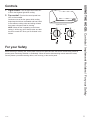 5
5
-
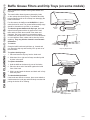 6
6
-
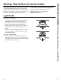 7
7
-
 8
8
-
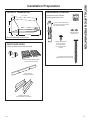 9
9
-
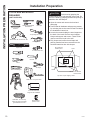 10
10
-
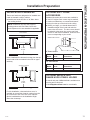 11
11
-
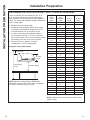 12
12
-
 13
13
-
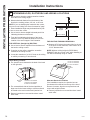 14
14
-
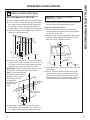 15
15
-
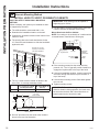 16
16
-
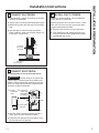 17
17
-
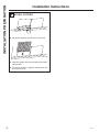 18
18
-
 19
19
-
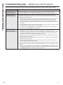 20
20
-
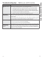 21
21
-
 22
22
-
 23
23
-
 24
24
-
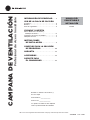 25
25
-
 26
26
-
 27
27
-
 28
28
-
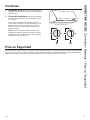 29
29
-
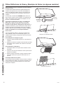 30
30
-
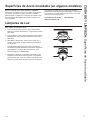 31
31
-
 32
32
-
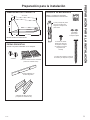 33
33
-
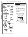 34
34
-
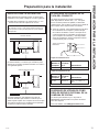 35
35
-
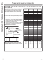 36
36
-
 37
37
-
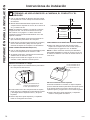 38
38
-
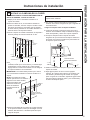 39
39
-
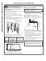 40
40
-
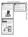 41
41
-
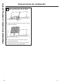 42
42
-
 43
43
-
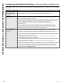 44
44
-
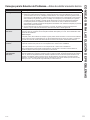 45
45
-
 46
46
-
 47
47
-
 48
48


GE CV48SSL1SS Manual de usuario
- Categoría
- Campanas de cocina
- Tipo
- Manual de usuario
en otros idiomas
- English: GE CV48SSL1SS User manual
Artículos relacionados
-
GE PV976N2SS El manual del propietario
-
GE ZV30HSR2SS Guía de instalación
-
GE ZV830SMSS Guía de instalación
-
-
-
GE ZV48SSJSS El manual del propietario
-
GE UVC9300SLSS Manual de usuario
-
-
GE Cafe Series CV966TSS El manual del propietario
-
GE CV936EK1DS El manual del propietario
Otros documentos
-
GE Profile PV976NSS El manual del propietario
-
Monogram ZV830SMSS Guía de instalación
-
GE Monogram ZV36SSJSS El manual del propietario
-
 Cafe CV936EKDS El manual del propietario
-
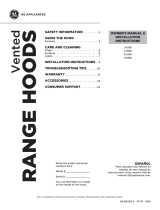 Cafe CV936EKDS Guía de instalación
-
Cafe CVW93014MWM El manual del propietario
-
Everbilt SEVHD Instrucciones de operación
-
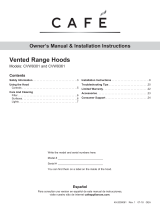 Cafe CVW93013MDS Guía de instalación
-
 arietta KIT0102873 Guía de instalación


