Genius STEP B7 Instrucciones de operación
- Categoría
- Abridor de puerta
- Tipo
- Instrucciones de operación

STEP - B7

AVVERTENZE PER L’INSTALLATORE
OBBLIGHI GENERALI PER LA SICUREZZA
1) ATTENZIONE! È importante per la sicurezza delle persone seguire attentamente tutta l’istruzione.
Una errata installazione o un errato uso del prodotto può portare a gravi danni alle persone.
2) Leggere attentamente le istruzioni prima di iniziare l’installazione del prodotto.
3) I materiali dell’imballaggio (plastica, polistirolo, ecc.) non devono essere lasciati alla portata dei
bambini in quanto potenziali fonti di pericolo.
4) Conservare le istruzioni per riferimenti futuri.
5) Questo prodotto è stato progettato e costruito esclusivamente per l’utilizzo indicato in questa
documentazione. Qualsiasi altro utilizzo non espressamente indicato potrebbe pregiudicare
l’integrità del prodotto e/o rappresentare fonte di pericolo.
6) GENIUS declina qualsiasi responsabilità derivata dall’uso improprio o diverso da quello per cui
l’automatismo è destinato.
7) Non installare l’apparecchio in atmosfera esplosiva: la presenza di gas o fumi infiammabili
costituisce un grave pericolo per la sicurezza.
8) Gli elementi costruttivi meccanici devono essere in accordo con quanto stabilito dalle Norme
EN 12604 e EN 12605.
Per i Paesi extra-CEE, oltre ai riferimenti normativi nazionali, per ottenere un livello di sicurezza
adeguato, devono essere seguite le Norme sopra riportate.
9) GENIUS non è responsabile dell’inosservanza della Buona Tecnica nella costruzione delle
chiusure da motorizzare, nonché delle deformazioni che dovessero intervenire nell’utilizzo.
10) L’installazione deve essere effettuata nell’osservanza delle Norme EN 12453 e EN 12445. Il livello
di sicurezza dell’automazione deve essere C+D.
11) Prima di effettuare qualsiasi intervento sull’impianto, togliere l’alimentazione elettrica e scollegare
le batterie.
12) Prevedere sulla rete di alimentazione dell’automazione un interruttore onnipolare con distanza
d’apertura dei contatti uguale o superiore a 3 mm. È consigliabile l’uso di un magnetotermico
da 6A con interruzione onnipolare.
13) Verificare che a monte dell’impianto vi sia un interruttore differenziale con soglia da 0,03 A.
14) Verificare che l’impianto di terra sia realizzato a regola d’arte e collegarvi le parti metalliche
della chiusura.
15) L’automazione dispone di una sicurezza intrinseca antischiacciamento costituita da un controllo
di coppia. E' comunque necessario verificarne la sogli di intervento secondo quanto previsto
dalle Norme indicate al punto 10.
16) I dispositivi di sicurezza (norma EN 12978) permettono di proteggere eventuali aree di pericolo
da Rischi meccanici di movimento, come ad Es. schiacciamento, convogliamento, cesoiamento.
17) Per ogni impianto è consigliato l’utilizzo di almeno una segnalazione luminosa nonché di un
cartello di segnalazione fissato adeguatamente sulla struttura dell’infisso, oltre ai dispositivi citati
al punto “16”.
18) GENIUS declina ogni responsabilità ai fini della sicurezza e del buon funzionamento dell’automa-
zione, in caso vengano utilizzati componenti dell’impianto non di produzione GENIUS.
19) Per la manutenzione utilizzare esclusivamente parti originali GENIUS.
20) Non eseguire alcuna modifica sui componenti facenti parte del sistema d’automazione.
21) L’installatore deve fornire tutte le informazioni relative al funzionamento manuale del sistema in
caso di emergenza e consegnare all’Utente utilizzatore dell’impianto il libretto d’avvertenze
allegato al prodotto.
22) Non permettere ai bambini o persone di sostare nelle vicinanze del prodotto durante il
funzionamento.
23) Tenere fuori dalla portata dei bambini radiocomandi o qualsiasi altro datore di impulso, per
evitare che l’automazione possa essere azionata involontariamente.
24) Il transito tra le ante deve avvenire solo a cancello completamente aperto.
25) L’Utente utilizzatore deve astenersi da qualsiasi tentativo di riparazione o d’intervento diretto e
rivolgersi solo a personale qualificato.
26) Non mettere in corto circuito i poli delle batterie e non tentare di ricaricarle con alimentatori
diversi dalle schede Master o Slave.
27) Non gettare le batterie esauste nei rifiuti ma smaltirle utilizzando gli appositi contenitori per
consentirne il riciclaggio. I costi di smaltimento sono già stati pagati dalla casa costruttrice.
28) Tutto quello che non è previsto espressamente in queste istruzioni non è permesso
IMPORTANT NOTICE FOR THE INSTALLER
GENERAL SAFETY REGULATIONS
1) ATTENTION! To ensure the safety of people, it is important that you read all the following
instructions. Incorrect installation or incorrect use of the product could cause serious harm to
people.
2) Carefully read the instructions before beginning to install the product.
3) Do not leave packing materials (plastic, polystyrene, etc.) within reach of children as such
materials are potential sources of danger.
4) Store these instructions for future reference.
5) This product was designed and built strictly for the use indicated in this documentation. Any other
use, not expressly indicated here, could compromise the good condition/operation of the
product and/or be a source of danger.
6) GENIUS declines all liability caused by improper use or use other than that for which the
automated system was intended.
7) Do not install the equipment in an explosive atmosphere: the presence of inflammable gas or
fumes is a serious danger to safety.
8) The mechanical parts must conform to the provisions of Standards EN 12604 and EN 12605.
For non-EU countries, to obtain an adequate level of safety, the Standards mentioned above
must be observed, in addition to national legal regulations.
9) GENIUS is not responsible for failure to observe Good Technique in the construction of the
closing elements to be motorised, or for any deformation that may occur during use.
10) The installation must conform to Standards EN 12453 and EN 12445. The safety level of the
automated system must be C+D.
11) Before attempting any job on the system, cut out electrical power and disconnect the
batteries.
12) The mains power supply of the automated system must be fitted with an all-pole switch with
contact opening distance of 3mm or greater. Use of a 6A thermal breaker with all-pole circuit
break is recommended.
13) Make sure that a differential switch with threshold of 0.03 A is fitted upstream of the system.
14) Make sure that the earthing system is perfectly constructed, and connect metal parts of the
means of the closure to it.
15) The automated system is supplied with an intrinsic anti-crushing safety device consisting of a
torque control. Nevertheless, its tripping threshold must be checked as specified in the
Standards indicated at point 10.
CONSIGNES POUR L'INSTALLATEUR
RÈGLES DE SÉCURITÉ
1) ATTENTION! Il est important, pour la sécurité des personnes, de suivre à la lettre toutes les
instructions. Une installation erronée ou un usage erroné du produit peut entraîner de graves
conséquences pour les personnes.
2) Lire attentivement les instructions avant d'installer le produit.
3) Les matériaux d'emballage (matière plastique, polystyrène, etc.) ne doivent pas être laissés
à la portée des enfants car ils constituent des sources potentielles de danger.
4) Conserver les instructions pour les références futures.
5) Ce produit a été conçu et construit exclusivement pour l'usage indiqué dans cette
documentation. Toute autre utilisation non expressément indiquée pourrait compromettre
l'intégrité du produit et/ou représenter une source de danger.
6) GENIUS décline toute responsabilité qui dériverait d'usage impropre ou différent de celui
auquel l'automatisme est destiné.
7) Ne pas installer l'appareil dans une atmosphère explosive: la présence de gaz ou de fumées
inflammables constitue un grave danger pour la sécurité.
8) Les composants mécaniques doivent répondre aux prescriptions des Normes EN 12604 et EN
12605.
Pour les Pays extra-CEE, l'obtention d'un niveau de sécurité approprié exige non seulement le
respect des normes nationales, mais également le respect des Normes susmentionnées.
9) GENIUS n'est pas responsable du non-respect de la Bonne Technique dans la construction des
fermetures à motoriser, ni des déformations qui pourraient intervenir lors de l'utilisation.
10) L'installation doit être effectuée conformément aux Normes EN 12453 et EN 12445. Le niveau de
sécurité de l'automatisme doit être C+D.
11) Couper l'alimentation électrique et déconnecter la batterie avant toute intervention sur
l'installation.
12) Prévoir, sur le secteur d'alimentation de l'automatisme, un interrupteur omnipolaire avec une
distance d'ouverture des contacts égale ou supérieure à 3 mm. On recommande d'utiliser un
magnétothermique de 6A avec interruption omnipolaire.
13) Vérifier qu'il y ait, en amont de l'installation, un interrupteur différentiel avec un seuil de 0,03 A.
14) Vérifier que la mise à terre est réalisée selon les règles de l'art et y connecter les pièces
métalliques de la fermeture.
15) L'automatisme dispose d'une sécurité intrinsèque anti-écrasement, formée d'un contrôle du
couple. Il est toutefois nécessaire d'en vérifier le seuil d'intervention suivant les prescriptions des
Normes indiquées au point 10.
16) Les dispositifs de sécurité (norme EN 12978) permettent de protéger des zones éventuellement
dangereuses contre les Risques mécaniques du mouvement, comme l'écrasement,
l'acheminement, le cisaillement.
17) On recommande que toute installation soit doté au moins d'une signalisation lumineuse, d'un
panneau de signalisation fixé, de manière appropriée, sur la structure de la fermeture, ainsi que
des dispositifs cités au point “16”.
18) GENIUS décline toute responsabilité quant à la sécurité et au bon fonctionnement de
l'automatisme si les composants utilisés dans l'installation n'appartiennent pas à la production
GENIUS.
19) Utiliser exclusivement, pour l'entretien, des pièces GENIUS originales.
20) Ne jamais modifier les composants faisant partie du système d'automatisme.
21) L'installateur doit fournir toutes les informations relatives au fonctionnement manuel du système
en cas d'urgence et remettre à l'Usager qui utilise l'installation les "Instructions pour l'Usager"
fournies avec le produit.
22) Interdire aux enfants ou aux tiers de stationner près du produit durant le fonctionnement.
23) Eloigner de la portée des enfants les radiocommandes ou tout autre générateur d'impulsions,
pour éviter tout actionnement involontaire de l'automatisme.
24) Le transit entre les vantaux ne doit avoir lieu que lorsque le portail est complètement ouvert.
25) L'Usager qui utilise l'installation doit éviter toute tentative de réparation ou d'intervention directe
et s'adresser uniquement à un personnel qualifié.
26) Ne pas mettre en court-circuit les pôles des batteries et ne pas tenter de les recharger avec
d'autres platines d'alimentation que les platines Maître ou Esclave.
27) Ne pas jeter les batteries épuisées à la poubelle, mais les éliminer dans les conteneurs
spécifiques pour le recyclage. Les coûts d'élimination des déchets ont déjà été payés par le
constructeur.
28) Tout ce qui n'est pas prévu expressément dans ces instructions est interdit.
16) The safety devices (EN 12978 standard) protect any danger areas against mechanical
movement Risks, such as crushing, dragging, and shearing.
17) Use of at least one indicator-light is recommended for every system, as well as a warning sign
adequately secured to the frame structure, in addition to the devices mentioned at point “16”.
18) GENIUS declines all liability as concerns safety and efficient operation of the automated
system, if system components not produced by GENIUS are used.
19) For maintenance, strictly use original parts by GENIUS.
20) Do not in any way modify the components of the automated system.
21) The installer shall supply all information concerning manual operation of the system in case of
an emergency, and shall hand over to the user the warnings handbook supplied with the
product.
22) Do not allow children or adults to stay near the product while it is operating.
23) Keep remote controls or other pulse generators away from children, to prevent the automated
system from being activated involuntarily.
24) Transit through the leaves is allowed only when the gate is fully open.
25) The user must not attempt any kind of repair or direct action whatever and contact qualified
personnel only.
26) Do not short-circuit the poles of the batteries and do not try to recharge the batteries with power
supply units other than Master or Slave cards.
27) Do not throw exhausted batteries into containers for other waste but dispose of them in the
appropriate containers to enable them to be recycled. Disposal costs have already been
paid for by the manufacturer.
28) Anything not expressly specified in these instructions is not permitted.

15
ENGLISH
Notes on STEP-B7 work batteries
The battery supplied with the STEP-B7 operator is a WORK BATTERY which directly powers the automated system. It is not a black-out
battery.
The battery is recharged by the control board to which it is connected via the transformer and a specific integrated circuit. Bear in
mind that it takes about 10 to 20 minutes of recharging to recover the energy used during an opening/closing cycle (this value varies
according to operating ambient temperature, battery life and type of system).
At installation, the batteries, due to storage, may not be fully charged and thus enable the gate to operate only a few times before
discharging completely. That is why, before installing a new system, we recommend to fully charge the supplied batteries, or provide
at least two identical fully charged batteries. In this way, you will be able to carry out the system programming operations and run the
functional checks.
HOW TO CHARGE THE BATTERIES FOR THE FIRST TIME
Charging can be done directly at the bench before the system is installed. Follow the instructions referring to the figure below:
1) connect the secondary winding of the 12Vac transformer (supplied separately) to connector J2 of the board and the primary
winding to mains voltage;
Note: if not using the transformer supplied by GENIUS, make sure that the secondary winding is 12Vac - 16VA.
2) connect the battery to the J4 connector on the board and allow it to charge for about 12 hours.
NOTE: While the batteries are being charged, LED P of the board (see Fig. 18 and para. 8.2) may change from fast flashing light (a flash
about every 250msec means the battery is discharged) to steady light (battery charged).Even if the LED stays lighted steady a little
while after you start charging, leave the batteries connected for the whole of the indicated time.

16
ENGLISH
Fig.01 Fig.02
STEP-B7 AUTOMATED SYSTEM
These instructions apply to the following model:
GENIUS STEP-B7
The STEP-B7 automated system automates residential sliding gates
with leaves of up to 5 m in length and 300 kg in weight.
It consists of non-reversing electro-mechanical gearmotor,
powered by a 12 Vdc work battery coupled to a control board
recharging the battery. The board can be programmed and is
used to set the following: function logics, work times (by self-
learning) and pause times, leaf speed, anti-crushing sensitivity,
and partial opening width.
The non-reversing system guarantees the gate will automatically
lock when the motor is not operating. A release system enables
the gate to be moved by hand in case of malfunction.
The STEP-B7 automated system was designed and built for
controlling vehicle access. Do not use for any other purpose.
1. DESCRIPTION AND TECHNICAL SPECIFICATIONS
Tab. 1 - Technical specifications of STEP-B7 operator
(1)
The consecutive cycles could be reduced by over 50% at low
temperatures (< 0°C).
• Dimensions in mm
2. DIMENSIONS
햲햲
햲
햲햲
rotarepo7B-PETS
햳햳
햳
햳햳
slenapedisevitcetorP
햴햴
햴
햴햴
noiniP
햵햵
햵
햵햵
esaelerlaunaM
햶햶
햶
햶햶
etalpnoitadnuoF
햷햷
햷
햷햷
dr
aoblortnoC
햸햸
햸
햸햸
draoblortnoCdnayrettaB
햹햹
햹
햹햹
yrettabkroW
햺햺
햺
햺햺
sdraugdnaH
햻햻
햻
햻햻
)lanoitpO(annetnA
)yletarapes
deilppuS(remrofsnarT
M
ledo
7B-PETS
ylppusrewoP )yrettabyb(cdV21
)W(rewopdebrosbadetaR 84
).nim/m(deepseerf-daolraenilxaM 51
)N(ecrofcitatS 051
y
rettabdegrahcnoselcycevitucesnoC 03~
)1(
emitegrahceryrettaB elcycdetelpmochcaerof'01~
)C°(erutarepmettneibmagnitarepO 55+÷02-
)gK(thgiewrotarepO 3
,5
ssalcnoitcetorP 44PI
)m(htgnelxamfaeL 5
)gk(thgiewxamfaeL 003
)mm(DxHxLsnoisnemidllarevorotarepO 2.giFees

17
ENGLISH
Fig.03
Fig.04
Fig.05
Fig.06
Fig.07
3. DESCRIPTION OF SYSTEM - ELECTRICAL EQUIPMENT
(standard system)
Notes:
1)To lay electric cables, use adequate rigid and/or flexible tubes.
2)To avoid any kind of interference always separate low voltage
connection cables from 230Vac power cables.
3)The transformer can be remotely located up to a distance of
100 m from the unit.
4. INSTALLING THE AUTOMATED SYSTEM
4.1. Preliminary checks
To ensure safety and an efficiently operating automated system,
make sure the following conditions are observed:
• The structure of the gate must be suitable for being automated.
In particular, check that the structure is sufficiently strong and
rigid, and that its dimensions and weight conform to those
indicated in the technical specifications.
• Make sure that the gate slides without any inclination.
• Make sure that the gate moves uniformly and correctly, without
any irregular friction during its entire travel.
• The soil must permit sufficient stability for the expansion plugs
securing the foundation plate.
• Check if the upper guide and travel limit mechanical stops are
installed.
• Remove any locks and lock bolts.
We advise you to have any metalwork carried out before the
automated system is installed.
4.2. Preparing the fundation plate
• Fit the 4 supplied caged nuts, as shown in Fig. 4, in the 4 square
holes of the plate.
4.3. Securing the foundation plate
1) The foundation plate must be located as shown in Fig. 5 (right
closing) or Fig. 6 (left closing) to ensure the rack and pinion mesh
correctly.
2) Secure the foundation plate to the floor, using adequate
expansion plugs (Fig. 7) and provide one or more sheaths for
routing the electric cables through the plate (Figs . 5-6 Ref. 1).
Using a spirit level, check if the plate is perfectly horizontal.
1) Operator with equipment.
2) Photocells
3) Key operated push-button
4) Flashing lamp
5) Radio receiver
*Use the dimensions according to type of rack
Galvanised rack 30x6 = 36.5mm
Galvanised rack 30x12 = 39.5mm
Nylon rack 30x20 = 41.5mm
Closing dir.
*Use the dimensions according to type of rack
Galvanised rack 30x6 = 36.5mm
Galvanised rack 30x12 = 39.5mm
Nylon rack 30x20 = 41.5mm
Closing dir.

18
ENGLISH
Fig.09
Fig.08
Fig.10
Fig.11
Fig.12
4.4. Positioning the operator
• Lay the electric cables for connection to the accessories and
power supply as shown in Fig. 3. To facilitate making the
connections, allow the cables to project by the required length
for connection to the terminal board, transformer and decoding
card (if provided).
• Position the operator on the plate, using the supplied screws as
shown in Fig. 8.
4.5. Adjusting the operator
• Adjust the distance of the operator from the gate by referring to
Fig. 9.
4.6. Securing the operator
• Temporarily fix the operator by slightly tightening the screws as
shown in Fig. 10.
4.7. Releasing the operator
Prepare the operator for manual operating mode as described
below:
• Open the protective door with a coin.
• Take the supplied key located inside the door, fit it in the release
system and turn it clockwise until it reaches the mechanical stop
(Fig. 11).
4.8 Installing the rack
4.8.1. Steel rack to be welded (Fig. 12)
1) Place the three threaded pawls on the rack element,
positioning them at the top of the slot. In this way, the slot play will
enable any adjustments to be made.
2) Manually take the gate into its closing position.
3) Lay the first piece of rack at appropriate level on the pinion
and weld the threaded pawl on the gate as shown in Fig. 15.
4) Move the gate manually, checking if the rack is resting on the
pinion, and weld the second and third pawl.
5) Bring another rack element near to the previous one, using a
piece of rack (as shown in Fig. 16 Ref.1) to synchronise the teeth of
the two elements.
6) Move the gate manually and weld the three threaded pawls,
so proceeding until the gate is fully covered.
4.8.2. Steel rack to be screwed (Fig. 13)
1) Manually take the gate into its closing position.
2) Lay the first piece of rack at the appropriate level on the pinion
and place the spacer between rack and gate, positioning it at
the top of the slot.
3) Mark the hole position on the gate. Drill a Ø 6.5 mm hole and
thread with a M8 mm tap. Screw the bolt.
4) Move the gate manually, checking if the rack is resting on the
pinion, and repeat the operations at point 3.
5) Bring another rack element near to the previous one, using a
piece of rack (as shown in Fig. 16 Ref.1) to synchronise the teeth of
the two elements.
6) Move the gate manually and carry out the securing operations
as for the first element, proceeding until the gate is fully covered.
Use the dimensions according to type of rack:
Galvanised rack 30x6
!!
!!
! A = 46.5mm and B =146mm
Galvanised rack 30x12
!!
!!
! A = 49.5mm and B =146mm
Nylon rack 30x20
!!
!!
! A = 51.5mm and B =112.5mm

19
ENGLISH
Fig.13
Fig.14
Fig.16
Fig.15
Fig.17
4.8.3. Nylon rack to be screwed (Fig. 14)
1) Manually take the gate into its closing position.
2) Lay on the pinion the first piece of rack at the appropriate level
and mark the hole position on the gate; make a hole with a 4 mm
bit and screw the 6x20 mm self-tapping screw with reinforcing
plate.
3) Move the gate manually, checking if the rack is resting on the
pinion, and repeat the operations at point 2.
4) Bring another rack element near to the previous one, using a
piece of rack (as shown in Fig. 16 Ref.1) to synchronise the teeth of
the two elements.
5) Move the gate manually and carry out the securing operations
as for the first element, proceeding until the gate is fully covered.
Notes on rack installation
• Make sure that, during the gate travel, all the rack elements
mesh correctly with the pinion.
• Do not, on any account, weld the rack elements either to the
spacers or to each other.
• When you have finished installing the rack, adjust the distance
between the pinion teeth and the rack groove, checking if the
distance is 1.5 mm (Fig. 17) along the entire travel, using the rack
slots.
• Manually check if the gate habitually reaches the travel limit
mechanical stops and make sure that there is no friction during
gate travel.
• Do not use grease or other lubricants between rack and pinion.

20
ENGLISH
DEL sDELgnimmargorP
P DELscitsongaiddnaNOrewoP
1P nottub-hsupgnimmargorp"noitcnuF"
2P nottub-hsupgnimmargorp
"eulaV"
1F A02FesufrotomdnayrettaB
1J draoblanimreTseirosseccA
2J draoblanimreTremrofsnarT
3J draoblanimretno
itcennocrotoM
4J rotcennocyrettaB
5J rotcennocrevieceR
01J draoblanimretrosnescitengaM
ylppusrewoP caV21
seirettaB 59x56x051snoisnemid-hA7cdV21bPcitemreH
scitsiretcarahcremrofsnarT AV61-caV21yr
adnoceS-zH06/05~caV032yramirP
tnerrucxamrotoM A51
erutarepmettneibmagnitarepO C°55+÷C°02-
sesufnoitcetorP A
02-1°N
noitcnufgnihsurc-itnA lortnoctnerruC/redocnE
cdV42tadaol.xamseirosseccA Am051
daolxamrotcennocdipaR
Am05
scigolnoitcnuFL citamotua-imeS/ecivedytefaS/citamotua"deppetS"/citamotuA
emitgnisolc/gninepO gninrae
l-flesyB
emitesuaP .ces03,02,01,5:elbammargorP
htdiwgninepolaitraP .mc081,051,021,09
deepS slevel4noelbatce
leS
tnemtsujdaecrofcitatS slevel4noelbatceleS
noitareleceD cinortcelE
stupnidraoblanimreT rosneS-.gnslctase
civedytefaS-.gnpotasecivedytefaS-potS-nepOyllaitraP-nepO
stuptuodraoblanimreT ylppusrewopcdV21-cdV42sei
rosseccA-thgil-rotacidni-pmalgnihsalF-rotoM
srotcennoC yrettaB-dracreviecer
snoitcnufelbammargorP deepsro
tarepo-ecrofgnihsurc-itna-htdiwgninepolaitrap-emitesuap-cigoL
Fig.18
CONTROL BOARD
WARNINGS
Attention: Before attempting any job on the control board (connections, maintenance), cut out electric power and the battery.
- Install, upstream of the system, a differential thermal breaker with adequate tripping threshold.
- Always separate 230VAC power cable from control and safety cables (push-buttons, receiver, photocells, etc.). To avoid any
electric noise, use separate sheaths or a shielded cable (with earthed shield).
5. BOARD LAYOUT
6. CONTROL BOARD TECHNICAL SPECIFICATIONS
Tab. 2 - Technical specifications
Jumpers position
must not be modified

21
ENGLISH
Fig.19
lanimreTnoitpircseD yrosseccadetcennoC
1ANEPO)dnammocgninepolatot( )nottub-hsupdetarepoyek.g.e(tcatnocANhti
weciveD
2BNEPO)dnammocgninepolaitrap( )nottub-hsupdetarepoyek.g.e(tcatnocANhtiweciveD
3POTS)dnammockcoletag(
.tcatnocCNhtiweciveD
)1(
4POWSF)tcatnocsecivedytefasgninepo( sllecotohP
)1(
5LCWSF)tcatnocsecivedytefasgnisolc( sllecotohP
)1(
6DESUTON/
8-7+ )ylppusrewopV42rofevitisop( Am051fonoitprosbalatotXAMseirosseccA
11-9.L.W)thgilrotacidniotylppus
rewop( pmalW5.0-V21
11-01PMAL)pmalgnihsalfotylppusrewop( pmalgnihsalfV21
51÷21- )ylppusrewopcdV42rofevitagen( /
* *
*
7. ELECTRICAL CONNECTIONS
Wire up as shown in Fig. 19
7.1 Description of J1 terminal board
Tab. 3 - Description of accessories connection
(1)
If you are not using any accessories, connect the terminal to earth (terminals 12 ÷ 15).
Note: when the automated system is idle, the power supply (+24 V) to accessories is disabled.
*
If not using the transformer supplied by GENIUS, make
sure that the secondary winding is 12Vac - 16VA.
**
For connection of photocells, see par. 7.4
Not
used

22
ENGLISH
Fig.20
7.2 Wiring the motor
Wire the STEP-B7 motor according to the gate closing direction as shown in the figure below.
Closing Dir.
Battery
BROWN
BLUE
Closing Dir.
Battery
BROWN
BLUE
Fig.21
Fig.22
Fig.23
7.3 Connection of photocells and safety devices
Before connecting the photocells (or other devices) we advise
you to select the type of operation according to the movement
area to be protected (see Fig. 21).
N.B.: If two devices with N.C. contact have the same function,
they must be connected to each other in series (Fig. 22).
N.B.: If two devices with N.A. contact have the same function,
they must be connected to each other in parallel (Fig. 23).
Connection of 2 NC contacts in series
Connection of 2 NA contacts in parallel
Opening or
opening/closing
safety devices
Closing safety devices
Opening safety devices

23
ENGLISH
Fig.24
Attention: a maximum of 2 pairs of photocells can be connected to the control board
Examples of photocell connections
1 pair of OPENING photocells
1 pair of CLOSING photocells
1 pair of CLOSING photocells and 1
pair of OPENING/CLOSING photocells
2 pairs of CLOSING photocells
connection of no devices
Fig.25
thgilydaetS.degrahcyrettabdnatneserprewopsniaM
sthgil(gnihsalfwolS
)dnocesyreve
eromtonrofdeilppustonrewo
psniaM
.degrahcyrettabhtiw,setunim5naht
syatsDELeht,snruterrewopsniamnehW
.ylidaetsdethgil
DELeht,deilppu
stonllitssirewopsniamfI
.)edomPEELS(ffoseog
sthgil(gnihsalfdipaR
)cesm052yreve
yrettabdnatneserprewopsnia
M
.)dekcoletag(degrahcsid
ehtlitnuyldiparhsalfotseunitnocDELehT
.yltneiciffusdegrahcersahyrettab
seogDELe
ht,deilppustonsirewopsniamfI
.)edomPEELS(ffo
FFOthgiL.)edomPEELS(deilppusrewopsniamoN
7.4 Connection of receiver card
Insert the receiver card in the block connector J5 (Fig. 18) as
indicated in Fig. 25.
For programming the receiver card, consult the individual
instructions.
8. START-UP
8.1 Powering up the system
After making all the cable connections we described previously,
power up the system to enable diagnostics, positioning of the
travel limit magnets, check of inputs status and programming.
Note: in the SLEEP mode, an OPEN pulse is sufficient to move the
gate (with charged battery)
8.2 Diagnostics
LED "P" (see Fig.18) - visible from inside the enclosure - performs the
diagnostics function. The LED has 4 statuses as shown in the table
below:
Tab. 4 - LED P status description

24
ENGLISH
Fig.26
Fig.27
Fig.28
8.3 Positioning the travel limit magnets
8.3.1 Prearrangement
The STEP-B7 operator is supplied with a sensor which, by detecting
the transit of two magnets secured to the top of the rack,
commands the gate to stop when closing or opening.
Procedure for correct positioning of the two supplied magnets:
• Assemble the magnets according to the type of rack used:
1) Galvanised rack 30x6 module 4 (Fig. 26 - Ref.
햲햲
햲햲
햲)
2) Galvanised rack 30x12 module 4 (Fig. 26 - Ref.
햳햳
햳햳
햳)
3) Reinforced nylon rack 30x20 module 4 (Fig. 26 - Ref.
햴햴
햴햴
햴)
8.3.2 Positioning
• Position the magnets on the rack as shown in Fig. 27 Ref
햲햲
햲햲
햲.
Make sure that distance between the magnet and the
operator's body is 5mm max (Fig. 27 Ref.
햳햳
햳햳
햳).
• Fully tighten the operator fixing screws(Fig. 10).
8.3.3 Adjustment and Fixing
• Press push-button P2 (Fig. 28 and par. 8.4) to enter the inputs
status function.
• Manually take the gate to opening position, but allow a space
of 2 cm from the travel limit mechanical stop.
• Slide the magnet on the rack (Fig. 29) until you see that LED1 on
the control board goes off (Fig. 28).
• Tighten the magnet's securing screws.
led 1
Fig.30
Fig.31
Fig.29
• Manually take the gate to closing position, but allow a space
of 2 cm from the travel limit mechanical stop.
• Slide the magnet on the rack (Fig. 30) until you see that LED1 on
the control board goes off (Fig. 28).
• Tighten the magnet's securing screws.
8.3.4 Operator locked
• Make sure the gate is in its closed position.
• Turn the release key anti-clockwise (Fig. 31).
• Move the gate until the release meshes.
• Remove the release key and put it back in its place; close the
protective door.

25
ENGLISH
deL
dethgiL
)tcatnocdesolc(
ffO
)tcatnocnepo(
AnepO=AevitcadnammoC evitcanidnammoC
BnepO=BevitcadnammoC evitcan
idnammoC
potS=C evitcanidnammoC evitcadnammoC
powsF=D degagnesidsecivedytefaS degagnesecivedytefaS
lcwsF=E de
gagnesidsecivedytefaS degagnesecivedytefaS
erosneS=1 degagnesidrosneS degagnerosneS
8.4 Status of inputs
The board has a function for checking the status of inputs on the
terminal board.
In all LEDS OFF status (LEDs both with letters and numbers), press
the P2 push-button.
When the LEDs light up, this indicates the inputs status as shown in
Tab. 5.
Tab. 5 - Description of inputs status LEDs
Notes:
• The status of LEDs with the gate closed at rest is shown in bold.
• In the inputs status function, push-button P1 commands an
OPEN A.
When checks have finished, once again press push-button P2 to
exit the inputs status function.
8.5 Programming
These are the basic settings of the board:
Function logic: A4
Pause times: B1
Partial opening width: C2
Static force: D3
Speed: E3
If you wish to execute customised programming (see par. from
8.5.1 to 8.5.5) and time-learning (see par.8.5.6) follow the steps in
the next pages.
8.5.1 Function Logic
In all LEDS OFF status, press push-button P1.
Led A will light up together with LED 4.
Press push-button P2, for a choice of 4 different function logics.
A1 automatic
A2 safety
A3 Step-by-step automatic
A4 Step-by-step semi-automatic (default)
8.5.2 Pause Times
Press push-button P1 again and LED B will light together with LED
1.
Press push-button P2, for a choice of 4 different pausetimes.
B1 5 seconds (default)
B2 10 seconds
B3 20 seconds
B4 30 seconds
8.5.3 Partial Opening Width
Press push-button P1 again and LED C will light together with LED
2.
Press push-button P2, for a choice of 4 different partial openings.
C1 90 cm
C2 120 cm (default)
C3 150 cm
C4 180 cm
8.5.4 Static Force
Press push-button P1 again and LED D will light together with LED
3.
Press push-button P2, for a choice of 4 different static forces.
D1 low
D2 medium low
D3 medium high (default)
D4 high

26
ENGLISH
sutatsthgil-rotacidnIsutatsetaG
ffOthgiLdesolC
dethgiLesuapninepO-nepO
gnihsalFgnisolC
dethgiLgninepO
dethgiLdek
coL
8.5.5 Speed
Press push-button P1 again and LED E will light together with LED
3.
Press push-button P2, for a choice of 4 different speeds
E1 low
E2 medium low
E3 medium high (default)
E4 high
8.5.6 Simple learning
If you press push-button P1 again, all 5 LEDs from A to E will light.
(Make sure that the gate is closed and operator locked)
If you press push-button P2 for 1 second, the gate will start moving
until the opening travel limit magnet engages the sensor on the
operator. The 5 LEDs flash during this stage.
After learning has been completed, the 5 LEDs remain lighted
steadily.
Press push-button P1 again to exit (all LEDs OFF). Give an OPEN A
pulse with the radio control or the key push-button to close the
gate.
8.6 Status of indicator light
If you wish to use a 12V-0.5W indicator light (terminal 9 - 11 of J1,
see Fig. 19), the following table shows the statuses of the indicator
light according to gate position.
Tab. 6 - Statuses of indicator light
Fig.32
8.7 Testing the automated system
After programming, run an accurate functional check of the
automated system and of all the accessories connected to it,
especially the safety devices.
9. MANUAL OPERATION
If the gate has to be moved manually due to a malfunction of
the automated system, use the release device as follows:
• Open the protective door with a coin.
• Take the supplied key located inside the door, fit it in the release
system and turn it clockwise until it reaches the mechanical
stop (fig. 32).
• Open or close the gate manually.
10. RESTORING NORMAL OPERATION MODE
Procedure to relock the gate:
• Manually take the gate back to its closed position.
• Turn the release key anti-clockwise until it reaches the
mechanical stop (Fig. 32).
• Move the gate until the release meshes.
• Remove the release key and put it back in its place; close the
protective door.
11. MAINTENANCE
Carry out the following jobs at least every 6 months:
•Check if the anti-crushing facility is correctly set.
•Check the efficiency of the release system.
•Check the efficiency of the safety devices and accessories.
12. REPAIRS
For any repairs, contact authorised Repair Centres.
UNLOCK
LOCK

27
ENGLISH
tluaF sesuacelbissoP noituloS
FFOPDELdraoB
nahteromrofdeilppusrewopsniamoN
degrahcyrettabhtiwsetunim5
ehtevomoteslupNEPOnaevigtsuJ
etag
yrettabhtiwdeilppusrewopsniamoN
.degrahcsid
sniamlitnudekcolyatslliwetagehT
siyrettabehtdnasnruterrewop
.
degrahceryltneiciffus
.nwodtuhsmetsysdetamotuA
dnammocynaybevomtonseodtI
rotcelesdetarepoyekrolortnocoid
ar(
.)hctiws
seirettabdegrahcsiD
roFFOsidraobehtfoPDELfikcehC
wolla,esacrettalehtnI.yldipargnihsalf
.egrah
cerotseirettabeht
tonslanimret)5dna4(WSFdna)3(POTS
.detcennoc
ehtninwohssagniriwehtkcehC
D,CsDELfikcehcos
ladnasnoitcurtsni
.sutatsstupniehtnoyltcerrocthgilEdna
.deliafesufdraoB
,yrassecenfi,dna)A02F(esufehtkce
hC
tiecalper
.nwodtuhsmetsysdetamotuA
.dnammocdetarepo-yekybylnosevoM
nahteromrofdeilppusrewopsniamoN
.sru
oh42
nehwdetavitca-ersirevieceroidarehT
eslupagnivigybrosnruterrewopsniam
ni;hctiwsrotcelesdetarepo-yeke
hthtiw
nrutertonseodrewopsniamfi,esacsiht
sireviecereht,sruoh42txenehtnihtiw
.nwodderewopniagaecno
lortno
coidarytluaF
ehtfikcehc,lortnocoidarrehtonagnisU
fi,dnayltcerrocgnitareposimetsys
oidarytluafehtecalper,
yrassecen
.lortnoc
draobreviecerytluaF
nwodtuhsllitssimetsysdetamotuaehtfI
lortnocoidartahtgnikcehcretfan
eve
.dracreviecerehtecalper,ytluaftonsaw
.nwodtuhsmetsysdetamotuA
tonseodetagehttub,snurrotomehT
.evom
tim
illevartehtdehcaersahrotomehT
.potslacinahcem
repsastengamtimillevartehtegnarrA
.snoitcurtsni
detamotuaeh
t,tnemevomgniruD
.nosaeronrofnoitomsesrevermetsys
yranigaminagniteem(wolootecroF
)elcatsbo
ehtnoselcatsbo
ynaeraerehtfikcehC
rosenotssahcus,etagehtfoetuor
citatsehtesaercnidna,tlahpsanevenu
.rotomehtfoecrof
ehts
mrofrepmetsysdetamotuaehT
nilevartgnisolc/gninepoeritne
.noitareleced
ecivedtimillevartehtnospotstiro
.no
itarelecedgnimrofreptuohtiw
.yltcerrocdetucexetongninraeL .snoitcurtsnirepsagninraeletucexE
sitengamtimi
llevartehtfonoitisopehT
.tcerrocton
sasecivedtimillevartfonoitisopkcehC
gninraeletucexednasnoitcurtsnire
p
niaga
potslacinahcemehtsehcaeretagehT
.deepsllufta
sitengamtimillevartehtfonoitisopehT
.tcerrocton
saseci
vedtimillevartfonoitisopkcehC
gninraeletucexednasnoitcurtsnirep
niaga
TROUBLESHOOTING

28
ENGLISH
a/7.baT
"1A"ACIGOL SESLUP
SUTATSETAGA-NEPOBNEPOPOTSSECIVEDYTEFASGNINEPOSECIVEDYTEFASGNISOLCECIVEDYTEFASLC/PO
DE
SOLC emitesuapretfasesolc-erdnasev/faelsnepO )delbasidNEPO(tceffeoNtceffeoN)delbasidNEPO(tceffeoN
ESUAPnoN
EPO emitesuapsdaoleR
noitarepospotS
tceffeoNemitesuapsdaoleR
GNISOLC yletaidemmisev/faelehtsnepo-eR tceffeoN
otsesreveryletaidemmI
nepo
,esaelerno,dnaskcoL
gninepotasesrever
GNINEPO tceffeoN
otsesreveryletaidemmI
esol
c
tceffeoN
,esaelerno,dnaskcoL
gnineposeunitnoc
DEKCOL sev/faelehtsesolCtceffeoNtceffeoN)delbasidNEPO(tceffeo
N
b/7.baT
"2A"ACIGOL SESLUP
SUTATSETAGA-NEPOBNEPOPOTSSECIVEDYTEFASGNINEPOSECIVEDYTEFASGNISOLCECIVEDYTEFASLC/PO
DE
SOLC emitesuapretfasesolc-erdnasev/faelsnepO )delbasidNEPO(tceffeoNtceffeoN)delbasidNEPO(tceffeoN
ESUAPnoN
EPO yletaidemmisev/faelehtsesolc-eR
noitarepospotS
tceffeoN ongepmisidla)otibiniNEPO("5opodeduihC
GNISOLC y
letaidemmisev/faelehtsnepo-eR tceffeoN
otsesreveryletaidemmI
nepo
,esaelerno,dnaskcoL
gninepotasesrever
GNI
NEPO yletaidemmisev/faelehtsesolc-eR
otsesreveryletaidemmI
esolc
tceffeoN
,esaelerno,dnaskcoL
gnineposeunit
noc
DEKCOL sev/faelehtsesolCtceffeoNtceffeoN)delbasidNEPO(tceffeoN
c/7.baT
"3A"ACIGOL SESLUP
SUTATSETAGA-NEPOBNEPOPOTSSECIVEDYTEFASGNINEPOSECIVEDYTEFASGNISOLCECIVEDYTEFASLC/PO
DE
SOLC emitesuapretfasesolc-erdnasev/faelsnepO )delbasidNEPO(tceffeoNtceffeoN)delbasidNEPO(tceffeoN
ESUAPnoN
EPO noitarepospotS
noitarepospotS
tceffeoNemitesuapsdaoleR
GNISOLC yletaidemmisev/faelehtsnepo-eR tceffeoN
ot
sesreveryletaidemmI
nepo
,esaelerno,dnaskcoL
gninepotasesrever
GNINEPO noitarepospotS
otsesreveryletaidemmI
esolc
tceffeoN
,esaelerno,dnaskcoL
gnineposeunitnoc
DEKCOL sev/faelehtsesolCtceffeoNtceffeoN)delbasidNEPO(tce
ffeoN
d/7.baT
"4A"ACIGOL SESLUP
SUTATSETAGA-NEPOBNEPOPOTSSECIVEDYTEFASGNINEPOSECIVEDYTEFASGNISOLCECIVEDYTEFASLC/PO
DE
SOLC sev/faelsnepO )delbasidNEPO(tceffeoNtceffeoN)delbasidNEPO(tceffeoN
NEPO yletaidemmisev/faelehtsesolc-e
R
noitarepospotS
tceffeoN
)delbasidNEPO(tceffeoN
GNISOLC noitarepospotS
otsesreveryletaidemmI
nepo
,esaelerno
,dnaskcoL
gninepotasesrever
GNINEPO noitarepospotS
otsesreveryletaidemmI
esolc
tceffeoN
,esaelerno,dnaskcoL
g
nineposeunitnoc
DEKCOL
noitceridesrevernignivomstratseR:NEPOretfA
yletaidemmisev/faelehtsesolc-eR:POTSre
tfA
)delbasidNEPO(tceffeoN
ti,nepotsumtifi(tceffeoN
)NEPOselbasid
)delbasidNEPO(tceffeoN

ADVERTENCIAS PARA EL INSTALADOR
REGLAS GENERALES PARA LA SEGURIDAD
1) ¡ATENCION! Es sumamente importante para la seguridad de las personas seguir atentamente las
presentes instrucciones. Una instalación incorrecta o un uso impropio del producto puede causar
graves daños a las personas.
2) Lean detenidamente las instrucciones antes de instalar el producto.
3) Los materiales del embalaje (plástico, poliestireno, etc.) no deben dejarse al alcance de los
niños, ya que constituyen fuentes potenciales de peligro.
4) Guarden las instrucciones para futuras consultas.
5) Este producto ha sido proyectado y fabricado exclusivamente para la utilización indicada en
el presente manual. Cualquier uso diverso del previsto podría perjudicar el funcionamiento del
producto y/o representar fuente de peligro.
6) GENIUS declina cualquier responsabilidad derivada de un uso impropio o diverso del previsto.
7) No instalen el aparato en atmósfera explosiva: la presencia de gas o humos inflamables
constituye un grave peligro para la seguridad.
8) Los elementos constructivos mecánicos deben estar de acuerdo con lo establecido en las
Normas EN 12604 y EN 12605.
Para los países no pertenecientes a la CEE, además de las referencias normativas nacionales,
para obtener un nivel de seguridad adecuado, deben seguirse las Normas arriba indicadas.
9) GENIUS no es responsable del incumplimiento de las buenas técnicas de fabricación de los cierres que
se han de motorizar, así como de las deformaciones que pudieran intervenir en la utilización.
10) La instalación debe ser realizada de conformidad con las Normas EN 12453 y EN 12445. E l
nivel de seguridad de la automación debe ser C+D.
11) Quiten la alimentación eléctrica y desconecten las baterías antes de efectuar cualquier
intervención en la instalación.
12) Coloquen en la red de alimentación de la automación un interruptor omnipolar con distancia
de apertura de los contactos igual o superior a 3 mm. Se aconseja usar un magnetotérmico
de 6A con interrupción omnipolar.
13) Comprueben que la instalación disponga línea arriba de un interruptor diferencial con umbral
de 0,03 A.
14) Verifiquen que la instalación de tierra esté correctamente realizada y conecten las partes
metálicas del cierre.
15) La automación dispone de un dispositivo de seguridad antiaplastamiento constituido por un
control de par. No obstante, es necesario comprobar el umbral de intervención según lo
previsto en las Normas indicadas en el punto 10.
16) Los dispositivos de seguridad (norma EN 12978) permiten proteger posibles áreas de peligro de
Riesgos mecánicos de movimiento, como por ej. aplastamiento, arrastre, corte.
17) Para cada equipo se aconseja usar por lo menos una señalización luminosa así como un cartel
de señalización adecuadamente fijado a la estructura del bastidor, además de los dispositivos
indicados en el “16”.
1 8) GENIUS declina toda responsabilidad relativa a la seguridad y al buen funcionamiento de la automación
si se utilizan componentes de la instalación que no sean de producción GENIUS.
19) Para el mantenimiento utilicen exclusivamente piezas originales GENIUS
20) No efectúen ninguna modificación en los componentes que forman parte del sistema de
automación.
21) El instalador debe proporcionar todas las informaciones relativas al funcionamiento del sistema
en caso de emergencia y entregar al usuario del equipo el manual de advertencias que se
adjunta al producto.
22) No permitan que niños o personas se detengan en proximidad del producto durante su
funcionamiento.
23) Mantengan lejos del alcance los niños los telemandos o cualquier otro emisor de impulso, para
evitar que la automación pueda ser accionada involuntariamente.
24) Sólo puede transitarse entre las hojas si la cancela está completamente abierta.
25) El usuario no debe por ningún motivo intentar reparar o modificar el producto, debe siempre
dirigirse a personal cualificado.
26) No pongan en cortocircuito los polos de las baterías y no intenten recargarlas con alimentadores
diferentes de las tarjetas Master o Slave.
27) No abandonen las baterías agotadas en el ambiente, hay que eliminarlas utilizando los
específicos contenedores para permitir el reciclaje de las mismas. Los costes de eliminación
ya han sido pagados por el fabricante.
28) Todo lo que no esté previsto expresamente en las presentes instrucciones debe entenderse como no
permitido
HINWEISE FÜR DEN INSTALLATIONSTECHNIKER
ALLGEMEINE SICHERHEITSVORSCHRIFTEN
1) ACHTUNG! Um die Sicherheit von Personen zu gewährleisten, sollte die Anleitung aufmerksam
befolgt werden. Eine falsche Installation oder ein fehlerhafter Betrieb des Produktes können zu
schwerwiegenden Personenschäden führen.
2) Bevor mit der Installation des Produktes begonnen wird, sollten die Anleitungen aufmerksam
gelesen werden.
3) Das Verpackungsmaterial (Kunststoff, Styropor, usw.) sollte nicht in Reichweite von Kindern
aufbewahrt werden, da es eine potentielle Gefahrenquelle darstellt.
4) Die Anleitung sollte aufbewahrt werden, um auch in Zukunft Bezug auf sie nehmen zu können.
5 ) Dieses Produkt wurde ausschließlich für den in diesen Unterlagen angegebenen Gebrauch entwickelt
und hergestellt. Jeder andere Gebrauch, der nicht ausdrücklich angegeben ist, könnte die Unversehrtheit
des Produktes beeinträchtigen und/oder eine Gefahrenquelle darstellen.
6) Die Firma GENIUS lehnt jede Haftung für Schäden, die durch unsachgemäßen oder nicht
bestimmungsgemäßen Gebrauch der Automatik verursacht werden, ab.
7 ) Das Gerät sollte nicht in explosionsgefährdeten Umgebungen installiert werden: das Vorhandensein von
entflammbaren Gasen oder Rauch stellt ein schwerwiegendes Sicherheitsrisiko dar.
8) Die mechanischen Bauelemente müssen den Anforderungen der Normen EN 12604 und EN
12605 entsprechen.
Für Länder, die nicht der Europäischen Union angehören, sind für die Gewährleistung eines
entsprechenden Sicherheitsniveaus neben den nationalen gesetzlichen Bezugsvorschriften die
oben aufgeführten Normen zu beachten.
9) Die Firma GENIUS übernimmt keine Haftung im Falle von nicht fachgerechten Ausführungen bei
der Herstellung der anzutreibenden Schließvorrichtungen sowie bei Deformationen, die eventuell
beim Betrieb entstehen.
10) Die Installation muß unter Beachtung der Normen EN 12453 und EN 12445 erfolgen. Die
Sicherheitsstufe der Automatik sollte C+D sein.
11) Vor der Ausführung jeglicher Eingriffe auf der Anlage sind die elektrische Versorgung und die
Batterie abzunehmen.
12) Auf dem Versorgungsnetz der Automatik ist ein omnipolarer Schalter mit Öffnungsabstand der
Kontakte von über oder gleich 3 mm einzubauen. Darüber hinaus wird der Einsatz eines
Magnetschutzschalters mit 6A mit omnipolarer Abschaltung empfohlen.
13) Es sollte überprüft werden, ob vor der Anlage ein Differentialschalter mit einer Auslöseschwelle
von 0,03 A zwischengeschaltet ist.
14) Es sollte überprüft werden, ob die Erdungsanlage fachgerecht ausgeführt wurde. Die Metallteile
der Schließung sollten an diese Anlage angeschlossen werden.
WAARSCHUWINGEN VOOR DE INSTALLATEUR
ALGEMENE VEILIGHEIDSVOORSCHRIFTEN
1) LET OP! Het is belangrijk voor de veiligheid dat deze hele instructie zorgvuldig wordt opgevolgd.
Een onjuiste installatie of foutief gebruik van het product kunnen ernstig persoonlijk letsel
veroorzaken.
2) Lees de instructies aandachtig door alvorens te beginnen met de installatie van het product.
3) De verpakkingsmaterialen (plastic, polystyreen, enz.) mogen niet binnen het bereik van
kinderen worden gelaten, want zij vormen een mogelijke bron van gevaar.
4) Bewaar de instructies voor raadpleging in de toekomst.
5) Dit product is uitsluitend ontworpen en gebouwd voor het doel dat in deze documentatie wordt
aangegeven. Elk ander gebruik, dat niet uitdrukkelijk wordt vermeld, zou het product kunnen
beschadigen en/of een bron van gevaar kunnen vormen.
6) GENIUS aanvaardt geen enkele aansprakelijkheid voor schade die ontstaat uit oneigenlijk
gebruik of ander gebruik dan waarvoor het automatische systeem is bedoeld.
7) Installeer het apparaat niet in een explosiegevaarlijke omgeving: de aanwezigheid van
ontvlambare gassen of dampen vormt een ernstig gevaar voor de veiligheid.
8) De mechanische bouwelementen moeten in overeenstemming zijn met de bepalingen van
de normen EN 12604 en EN 12605.
Voor niet-EEG landen moeten, om een goed veiligheidsniveau te bereiken, behalve de
nationale voorschriften ook de bovenstaande normen in acht worden genomen.
9) GENIUS is niet aansprakelijk als de regels der goede techniek niet in acht genomen zijn bij de
bouw van het sluitwerk dat gemotoriseerd moet worden, noch voor vervormingen die zouden
kunnen ontstaan bij het gebruik.
10) De installatie dient te geschieden in overeenstemming met de normen EN 12453 en EN 12445.
Het veiligheidsniveau van het automatische systeem moet C+D zijn.
11) Alvorens ingrepen te gaan verrichten op de installatie moet de elektrische voeding worden
weggenomen en moeten de batterijen worden afgekoppeld.
12) Zorg op het voedingsnet van het automatische systeem voor een meerpolige schakelaar met
een opening tussen de contacten van 3 mm of meer. Het wordt geadviseerd een
magnetothermische schakelaar van 6A te gebruiken met meerpolige onderbreking.
13) Controleer of er bovenstrooms van de installatie een differentieelschakelaar is geplaatst met
een limiet van 0,03 A.
14) Controleer of de aardingsinstallatie vakkundig is aangelegd en sluit er de metalen delen van
het sluitsysteem op aan.
15) Het automatische systeem beschikt over een intrinsieke beveiliging tegen inklemming, bestaande uit
een controle van het koppel. De inschakellimiet hiervan dient echter te worden gecontroleerd volgens
de bepalingen van de normen die worden vermeld onder punt 10.
16) De veiligheidsvoorzieningen (norm EN 12978) maken het mogelijk eventuele gevaarlijke
gebieden te beschermen tegen Mechanische gevaren door beweging, zoals bijvoorbeeld
inklemming, meesleuren of amputatie.
17) Het wordt voor elke installatie geadviseerd minstens één lichtsignaal te gebruiken alsook een
waarschuwingsbord dat goed op de constructie van het hang- en sluitwerk dient te worden
bevestigd, afgezien nog van de voorzieningen die genoemd zijn onder punt “16”.
18) GENIUS aanvaardt geen enkele aansprakelijkheid voor wat betreft de veiligheid en de goede
werking van het automatische systeem, als er in de installatie gebruik gemaakt wordt van
componenten die niet door GENIUS zijn geproduceerd.
19) Gebruik voor het onderhoud uitsluitend originele GENIUS-onderdelen.
20) Verricht geen wijzigingen op componenten die deel uitmaken van het automatische systeem.
21) De installateur dient alle informatie te verstrekken over de handbediening van het systeem in
noodgevallen, en moet de gebruiker van de installatie het bij het product geleverde boekje
met aanwijzingen overhandigen.
22) Sta het niet toe dat kinderen of volwassenen zich ophouden in de buurt van het product terwijl
dit in werking is.
23) Houd radio-afstandsbedieningen of alle andere impulsgevers buiten het bereik van kinderen,
om te voorkomen dat het automatische systeem onopzettelijk kan worden aangedreven.
24) Ga alleen tussen de vleugels door als het hek helemaal geopend is.
25) De gebruiker mag geen pogingen tot reparatie doen of directe ingrepen plegen, en dient zich
uitsluitend te wenden tot gekwalificeerd personeel.
26) Breng de polen van de batterijen niet in kortsluiting en probeer niet de batterijen op te laden
met andere voeders dan de Master- of Slave-kaarten.
27) Gooi lege batterijen niet weg bij het gewone afval, maar maak gebruik van de speciale
verzamelbakken om recycling mogelijk te maken. De kosten voor afvalverwerking zijn al
betaald door de fabrikant.
28) Alles wat niet uitdrukkelijk in deze instructies wordt aangegeven, is niet toegestaan
1 5) Die Automation verfügt über eine eingebaute Sicherheitsvorrichtung für den Quetschschutz, die aus einer
Drehmomentkontrolle besteht. Es ist in jedem Falle erforderlich, deren Eingriffsschwelle gemäß der
Vorgaben der unter Punkt 10 angegebenen Vorschriften zu überprüfen.
16) Die Sicherheitsvorrichtungen (Norm EN 12978) ermöglichen den Schutz eventueller
Gefahrenbereiche vor mechanischen Bewegungsrisiken, wie zum Beispiel Quetschungen,
Mitschleifen oder Schnittverletzungen.
1 7 ) Für jede Anlage wird der Einsatz von mindestens einem Leuchtsignal empfohlen sowie eines Hinweisschildes,
das über eine entsprechende Befestigung mit dem Aufbau des Tors verbunden wird. Darüber hinaus sind
die unter Punkt “16” erwähnten Vorrichtungen einzusetzen.
18) Die Firma GENIUS lehnt jede Haftung hinsichtlich der Sicherheit und des störungsfreien Betriebs
der Automatik ab, soweit Komponenten auf der Anlage eingesetzt werden, die nicht im Hause
GENIUS hergestellt wurden.
19) Bei der Instandhaltung sollten ausschließlich Originalteile der Firma GENIUS verwendet werden.
20) Auf den Komponenten, die Teil des Automationssystems sind, sollten keine Veränderungen
vorgenommen werden.
21) Der Installateur sollte alle Informationen hinsichtlich des manuellen Betriebs des Systems in
Notfällen liefern und dem Betreiber der Anlage das Anleitungsbuch, das dem Produkt beigelegt
ist, übergeben.
22) Weder Kinder noch Erwachsene sollten sich während des Betriebs in der unmittelbaren Nähe
der Automation aufhalten.
23) Die Funksteuerungen und alle anderen Impulsgeber sollten außerhalb der Reichweite von Kindern
aufbewahrt werden, um ein versehentliches Aktivieren der Automation zu vermeiden.
24) Der Durchgang oder die Durchfahrt zwischen den Flügeln darf lediglich bei vollständig geöffnetem
Tor erfolgen.
25) Der Betreiber sollte keinerlei Reparaturen oder direkte Eingriffe auf der Automation ausführen,
sondern sich hierfür ausschließlich an qualifiziertes Fachpersonal wenden.
26) Die Pole der Batterien sollten nicht kurzgeschlossen werden. Die Batterien sollten nicht mit
Speisegeräten geladen werden, die von den Karten Master oder Slave abweichen.
27) Leere Batterien gehören nicht in den Hausmüll, sondern sind über die entsprechenden Behälter
zu entsorgen, damit sie dem Recycling zugeführt werden können. Die Entsorgungskosten
wurden bereits vom Hersteller bezahlt.
28) Alle Vorgehensweisen, die nicht ausdrücklich in der vorliegenden Anleitung vorgesehen sind, sind
nicht zulässig

00058I0523 Rev.2
Le descrizioni e le illustrazioni del presente manuale non sono impegnative. GENIUS si riserva il diritto, lasciando inalterate le caratteristiche essenziali dell’apparecchiatura, di apportare in qualunque momento
e senza impegnarsi ad aggiornare la presente pubblicazione, le modifiche che essa ritiene convenienti per miglioramenti tecnici o per qualsiasi altra esigenza di carattere costruttivo o commerciale.
The descriptions and illustrations contained in the present manual are not binding. GENIUS reserves the right, whils leaving the main features of the equipments unaltered, to undertake any modifications to holds
necessary for either technical or commercial reasons, at any time and without revising the present publication.
Les descriptions et les illustrations du présent manuel sont fournies à titre indicatif. GENIUS se réserve le droit d’apporter à tout moment les modifications qu’elle jugera utiles sur ce produit tout en conservant les
caractéristiques essentielles, sans devoir pour autant mettre à jour cette publication .
Las descripciones y las ilustraciones de este manual no comportan compromiso alguno. GENIUS se reserva el derecho, dejando inmutadas las características esenciales de los aparatos, de aportar, en
cualquier momento y sin comprometerse a poner al día la presente publicación, todas las modificaciones que considere oportunas para el perfeccionamiento técnico o para cualquier otro tipo de exigencia
de carácter constructivo o comercial.
Die Beschreibungen und Abbildungen in vorliegendem Handbuch sind unverbindlich. GENIUS behält sich das Recht vor, ohne die wesentlichen Eigenschaften dieses Gerätes zu verändern und ohne
Verbindlichkeiten in Bezung auf die Neufassung der vorliegenden Anleitungen, technisch bzw, konstruktiv / kommerziell bedingte Verbesserungen vorzunehmen.
De beschrijvingen in deze handleiding zijn niet bindend. GENIUS behoudt zich het recht voor op elk willekeurig moment de veranderingen aan te brengen die het bedrijf nuttig acht met het oog op technische
verbeteringen of alle mogelijke andere productie- of commerciële eisen, waarbij de fundamentele eigenschappen van het apparaat gehandhaafd blijven, zonder zich daardoor te verplichten deze
publicatie bij te werken.
Timbro rivenditore: / Distributor’s stamp: / Timbre de l’agent: /
Sello del revendedor: / Fachhändlerstempel: / Stempel dealer:
GENIUS S.p.A.
Via Padre Elzi, 32
24050 - Grassobbio
BERGAMO-ITALY
tel. 0039.035.4242511
fax. 0039.035.4242600
www.geniusg.com
DICHIARAZIONE CE DI CONFORMITÁ
Fabbricante: GENIUS S.p.A.
Indirizzo: Via Padre Elzi, 32 - 24050 - Grassobbio-
Bergamo - ITALIA
Dichiara che: L’operatore mod. STEP-B7
• è costruito per essere incorporato in una macchina o per
essere assemblato con altri macchinari per costituire una
macchina ai sensi della Direttiva 2006/42/CE;
• è conforme ai requisiti essenziali di sicurezza delle seguenti
altre direttive CEE:
• 2006/95/CE direttiva Bassa Tensione.
• 2004/108/CE direttiva Compatibilità elettromagnetica.
Inoltre dichiara che non è consentito mettere in servizio il macchinario
fino a che la macchina in cui sarà incorporato o di cui diverrà
componente sia stata identificata e ne sia stata dichiarata la
conformità alle condizioni della Direttiva 2006/42/CEE e successive
modifiche.
Grassobbio, 30 Dicembre 2009
L’Amministratore Delegato
D. Gianantoni
CE DECLARATION OF ONFORMITY
Manufacturer: GENIUS S.p.A.
Address: Via Padre Elzi, 32 - 24050 - Grassobbio-
Bergamo - ITALY
Declares that: Operator mod. STEP-B7
• is built to be integrated into a machine or to be assembled
with other machinery to create a machine under the
provisions of Directive 2006/42/EC;
• conforms to the essential safety requirements of the following
EEC directives:
• 2006/95/EC Low Voltage directive.
• 2004/108/EC Electromagnetic Compatibility directive.
and also declares that it is prohibited to put into service the machinery
until the machine in which it will be integrated or of which it will
become a component has been identified and declared as
conforming to the conditions of Directive 2006/42/EEC and
subsequent modifications.
Grassobbio, December 30, 2009
Managing Director
D. Gianantoni
DÉCLARATION CE DE CONFORMITÉ
Fabricant: GENIUS S.p.A.
Adresse: Via Padre Elzi, 32 - 24050 - Grassobbio-
Bergamo - ITALIE
Déclare que: L’opérateur mod. STEP-B7
• est construit pour être incorporé dans une machine ou pour
être assemblé à d’autres appareillages, afin de constituer
une machine conforme aux termes de la Directive 2006/42/
CE;
• est conforme aux exigences essentielles de sécurité des
directives CEE suivantes:
• 2006/95/CE directive Basse Tension.
• 2004/108/CE directive Compatibilité Électromagnétique.
On déclare en outre que la mise en service de l’outillage est interdite
tant que la machine à laquelle il sera incorporé ou dont il deviendra
un composant n’a pas été identifiée et déclarée conforme aux
conditions de la Directive 2006/42/CEE et modifications successives.
Grassobbio, 30 décembre 2009
L’Administrateur Délégué
D. Gianantoni
CE-KONFORMITÄTSERKLÄRUNG
Hersteller: GENIUS S.p.A.
Adresse: Via Padre Elzi, 32 - 24050 -
Grassobbio- Bergamo – ITALIEN
Erklärt, dass: Der Antrieb STEP-B7
• hergestellt wurde, um in eine Maschine eingebaut oder mit
anderen Maschinen zu einer Maschine zusammengebaut zu
werden, gemäß der Richtlinien 2006/42/EG;
• den wesentlichen Sicherheitsanforderungen der folgenden
EWG-Richtlinien entspricht:
• 2006/95/EG Niederspannungsrichtlinie.
•2004/108/EG Richtlinie zur elektromagnetischen
Verträglichkeit.
und erklärt außerdem, dass die Inbetriebnahme solange
untersagt ist, bis die Maschine, in welche diese Maschine
eingebaut wird oder von der sie ein Bestandteil ist, bestimmt
wurde und deren Übereinstimmung mit den Voraussetzungen
der Richtlinie 2006/42/EWG und nachträgliche Änderungen.
Grassobbio, 30. Dezember 2009
Geschäftsführer
D. Gianantoni
DECLARACIÓN CE DE CONFORMIDAD
Fabricante: GENIUS S.p.A.
Dirección: Via Padre Elzi, 32 - 24050 - Grassobbio-
Bergamo - ITALIA
Declara que: El operador mod. STEP-B7
• ha sido fabricado para ser incorporado en una máquina o
para ser ensamblado con otras maquinarias para constituir
una máquina de conformidad con la Directiva 2006/42/CE;
• cumple con los requisitos esenciales de seguridad de las
siguientes directivas CEE:
•2006/95/CE directiva de Baja Tensión.
•2004/108/CE directiva de Compatibilidad
Electromagnética.
Asimismo declara que no está permitido poner en funcionamiento
la maquinaria hasta que la máquina en la que deberá incorporarse
o de la cual será un componente haya sido identificada y se haya
declarado su conformidad con las condiciones de la Directiva
2006/42/CEE y sucesivas modificaciones.
Grassobbio, 30 de diciembre 2009
El Administrador Delegado
D. Gianantoni
CE VERKLARING VAN OVEREENSTEMMING
Fabrikant: GENIUS S.p.A.
Adres: Via Padre Elzi, 32 - 24050 - Grassobbio-
Bergamo - ITALIE
Verklaart dat: De aandrijving mod. STEP-B7
• is gebouwd voor opname in een machine of voor assemblage
met andere machines, met het doel een machine te vormen
in de zin van de Richtlijn 2006/42/EG;
•in overeenstemming is met de fundamentele veiligheidseisen
van de volgende EEG-richtlijnen:
• 2006/95/EG Laagspanningsrichtijn.
• 2004/108/EG richtlijn Elektromagnetische Compatibiliteit.
En verklaart daarnaast dat het niet is toegestaan het apparaat in
bedrijf te stellen tot de machine waarin het wordt ingebouwd of
waar het een onderdeel van zal worden, is geïdentificeerd, en
conform de vereisten van Richtlijn 2006/42/EEG en
daaropvolgende wijzigingen.
Grassobbio, 30 december 2009
De Algemeen Directeur
D. Gianantoni

1
Step-B7
Fig. 1 Fig.2
ITALIANO
SBLOCCA
UNLOCK
DEBLOQUE
DESBLOQUEA
VERRIEGELT
DEBLOKKEN
BLOCCA
LOCK
BLOQUE
BLOQUEA
ENTRIEGELT
BLOKKEN
Guida per l'utente - User’s guide - Instructions pour l'usager - Guía para el usuario - Führer
für den Benutzer - Gids voor de gebruiker
Leggere attentamente le istruzioni prima di utilizzare il prodotto e
conservarle per eventuali necessità future
NORME GENERALI DI SICUREZZA
L'automazione STEP-B7, se correttamente installata ed utilizzata,
garantisce un elevato grado di sicurezza.
Alcune semplici norme di comportamento possono evitare inoltre
inconvenienti accidentali:
• Non transitare tra il cancello quando questo è in movimento.
Prima di transitare tra il cancello, attendere l'apertura comple-
ta.
• Non sostare assolutamente sulla via di movimento del cancello.
• Non sostare e non permettere a bambini, persone o cose di
sostare nelle vicinanze dell’automazione, evitandolo ancor più
durante il funzionamento.
• Tenere fuori dalla portata dei bambini, radiocomandi o qualsi-
asi altro datore d’impulso per evitare che l'automazione possa
essere azionata involontariamente.
• Non permettere ai bambini di giocare con l’automazione.
• Non contrastare volontariamente il movimento del cancello.
• Evitare che rami o arbusti possano interferire col movimento del
cancello
• Mantenere efficienti e ben visibili i sistemi di segnalazione lumi-
nosa.
• Non tentare di azionare manualmente il cancello se non dopo
averlo sbloccato.
• In caso di malfunzionamento, sbloccare il motoriduttore per
consentire l’accesso ed attendere l’intervento tecnico di perso-
nale qualificato.
• Prima di intervenire sullo sblocco manuale scollegare le batte-
rie.
• Non eseguire alcuna modifica sui componenti facenti parte
del sistema d’automazione.
• Astenersi da qualsiasi tentativo di riparazione o d’intervento
diretto e rivolgersi solo a personale qualificato.
• Far verificare almeno semestralmente l’efficienza dell’automa-
zione, dei dispositivi di sicurezza e degli accessori.
DESCRIZIONE
Le presenti istruzioni sono valide per il seguente modello:
GENIUS STEP-B7
L’automazione STEP-B7 per cancelli scorrevoli residenziali è costi-
tuita da un operatore elettromeccanico irreversibile, alimentato
a 12 Vdc e abbinato ad un'apparecchiatura elettronica dotata
di batteria di lavoro (non di black-out), che garantisce il funziona-
mento dell'automazione anche in caso di interruzione della ten-
sione di rete.
Il sistema irreversibile garantisce il blocco meccanico del cancello
quando il motore non è in funzione. Uno sblocco manuale rende
manovrabile il cancello in caso di disservizio.
Il funzionamento del motoriduttore è gestito da una centralina
elettronica di comando , alloggiata all'interno del motoriduttore
con adeguato grado di protezione agli agenti atmosferici.
Il cancello normalmente si trova in posizione di chiusura.
Quando la centralina elettronica riceve un comando di apertu-
ra tramite il radiocomando o qualsiasi altro datore di impulso,
aziona il motoriduttore ottenendo il movimento del cancello, fino
alla posizione di apertura che consente l’accesso.
Se è stato impostato il funzionamento automatico, le ante si
richiudono da sole dopo il tempo di pausa selezionato.
Se è stato impostato il funzionamento semiautomatico, è neces-
sario inviare un secondo impulso per ottenere la richiusura.
Un impulso di stop (se previsto) arresta sempre il movimento.
Per il dettagliato comportamento dell'automazione nelle diverse
logiche di funzionamento, fare riferimento al Tecnico installatore.
Nelle automazioni sono presenti dispositivi di sicurezza che impe-
discono il movimento del cancello quando un ostacolo si trova
nella zona da loro protetta.
L'automazione STEP-B7 è dotata di un dispositivo regolabile di
antischiacciamento che, in caso di contatto con un ostacolo,
inverte il movimento del cancello.
La segnalazione luminosa indica il movimento in atto del cancel-
lo.
FUNZIONAMENTO MANUALE
Nel caso sia necessario azionare manualmente il cancello a cau-
sa di disservizio dell'automazione, agire sul dispositivo di sblocco
come segue:
• Aprire lo sportello di protezione utilizzando una moneta .
• Estrarre la chiave in dotazione riposta all'interno dello sportello;
inserirla nell'apposito sistema di sblocco e ruotarla in senso orario
fino alla battuta meccanica (Fig. 1).
• Effettuare manualmente la manovra di apertura o chiusura.
RIPRISTINO DEL FUNZIONAMENTO NORMALE
• Riportare manualmente il cancello in posizione di chiuso.
• Ruotare la chiave di sblocco in senso antiorario fino alla battu-
ta meccanica (Fig. 2).
• Muovere il cancello fino all'ingranamento dello sblocco.
• Estrarre la chiave di sblocco e riporla nell'apposita sede; chiu-
dere lo sportello di protezione.

2
ENGLISH
Read the instructions carefully before using the product and store
them for future use
GENERAL SAFETY REGULATIONS
If correctly installed and used, the STEP-B7 automated system
ensures a high degree of safety.
Some simple rules on behaviour can prevent accidental trouble:
• Do not pass through the gate when it is moving. Wait for the
gate to open fully before passing through it.
• Do not, on any account, stand in the gate's movement range.
• Do not stand near the automated system or allow children,
persons or things to stand or lie there, especially while it is in use.
• Keep remote controls or other pulse generators away from
children, to prevent the automated system from being activated
involuntarily.
• Do not allow children to play with the automated system.
• Do not willingly obstruct gate movement.
• Prevent any branches or shrubs from interfering with gate
movement.
• Keep indicator-lights efficient and easy to see.
• Do not attempt to activate the gate by hand unless you have
released it.
• In the event of malfunctions, release the gearmotor to allow
access and wait for qualified technical personnel to do the
necessary work.
• Before using the manual release, disconnect the batteries.
• Do not in any way modify the components of the automated
system.
• Do not attempt any kind of repair or direct action whatever
and contact qualified personnel only.
• At least every six months: arrange a check of the automated
system, safety devices and accessories.
DESCRIPTION
These instructions apply to the following model:
GENIUS STEP-B7
The STEP-B7 automated system for residential sliding gates consists
of a non-reversing electro-mechanical operator, powered on 12
Vdc, coupled to a control board with a work battery (not a
black-out battery), ensuring operation even in the event of a
mains power cut.
The non-reversing system guarantees the gate will automatically
lock when the motor is not operating. A release system enables
the gate to be moved by hand in case of malfunction.
The gearmotor is controlled by an electronic control unit housed
inside the gearmotor where it is adequately protected against
atmospheric agents.
The gates is normally in its closed position.
When the electronic control unit receives an opening command
via the radio control or any other pulse generator, it activates the
gearmotor to move the gate until it reaches the opening position
to allow access.
If automatic mode was set, the leaves closes automatically after
the selected pause time has elapsed.
If the semi-automatic mode was set, a second pulse must be sent
to close the gate again.
A stop pulse (if supplied) always stops movement.
For details on the behaviour of the automated system in different
function logics, consult the installation Technician.
Automated systems include safety devices that prevent the gate
from moving when there is an obstacle in the area they protect.
The STEP-B7 automated system is provided with an adjustable
anti-crushing device which reverses gate movement in case of
contact with an obstacle.
The warning-light indicates that the gate is currently moving.
MANUAL OPERATION
If the gate has to be moved manually due to a fault of the
automated system, use the release device as follows:
• Open the protective door with a coin.
• Take the supplied key located inside the door, fit it in the release
system and turn it clockwise until it reaches the mechanical stop
(Fig. 1).
• Open or close the gate manually.
RESTORING NORMAL OPERATION MODE
• Manually take the gate back to its closed position.
• Turn the release key anti-clockwise until it reaches the
mechanical stop (Fig. 2).
• Move the gate until the release meshes.
• Remove the release key and put it back in its place; close the
protective door.
FRANÇAIS
Lire attentivement les instructions avant d'utiliser le produit et les
conserver pour toute nécessité future.
NORMES GENERALES DE SECURITE
S'il est correctement installé et utilisé, l'automatisme STEP-B7 garantit
un haut niveau de sécurité.
Par ailleurs quelques normes simples de comportement peuvent
éviter les accidents:
• Ne pas transiter par le portail quand ce dernier est en
mouvement. Avant de transiter par le portail, attendre l'ouvertu-
re complète.
• Ne stationner en aucun cas sur la voie du mouvement du portail.
• Ne pas stationner et interdire aux enfants et aux tiers de stationner
près de l'automatisme; ne pas y interposer d'objets; respecter
plus encore cette norme durant le fonctionnement.
• Eloigner de la portée des enfants les radiocommandes ou tout
autre générateur d'impulsions, pour éviter tout actionnement
involontaire de l'automatisme.
• Interdire aux enfants de jouer avec l'automatisme.
• Ne pas empêcher volontairement le mouvement du portail.
• Eviter que des branches ou des arbustes n’entravent le
mouvement du portail.
• Faire en sorte que les systèmes de signalisation lumineuse soient
toujours fiables et bien visibles.
• N’actionner manuellement le portail qu’après l’avoir
déverrouillé.
• En cas de dysfonctionnement, déverrouiller le motoréducteur
pour permettre l’accès et attendre l’intervention technique du
personnel qualifié.
• Avant d'intervenir sur le déverrouillage manuel, débrancher les
batteries.
• Ne jamais modifier les composants faisant partie du système
d'automatisme.
•Eviter toute tentative de réparation ou d'intervention directe et
s'adresser uniquement à un personnel qualifié.
• Faire vérifier, tous les six mois au moins, la fiabilité de l'automatisme,
des dispositifs de sécurité et des accessoires.
DESCRIPTION
Ces instructions sont valables pour le modèle suivant:
GENIUS STEP-B7
L’automatisme STEP-B7 pour portails coulissants domestiques est
constitué par un opérateur électromécanique irréversible,
alimenté à 12 Vcc et associé à une armoire électronique dotée
d'une batterie de fonctionnement (et non pas de black-out), qui
garantit le fonctionnement de l'automatisme même en cas de
coupure de courant.
Le système irréversible garantit le blocage mécanique du portail
quand le moteur n'est pas en fonction. Un déverrouillage manuel
permet de manœuvrer le portail en cas de dysfonctionnement.
Le fonctionnement du motoréducteur est géré par une centrale
électronique de commande, logée à l'intérieur du motoréducteur
avec un degré de protection adéquat contre les agents
atmosphériques.
Le portail se trouve normalement en position de fermeture.
Quand la centrale électronique reçoit une commande d'ouver-
ture par l'intermédiaire de la radiocommande ou de tout autre
générateur d'impulsion, elle actionne le motoréducteur obtenant
le mouvement du portail, jusqu'à la position d'ouverture qui permet
l'accès.
Si on a sélectionné le fonctionnement automatique, les vantaux
se referment d'eux-mêmes au bout du temps de pause sélectionné.
Si on a sélectionné le fonctionnement semi-automatique, envoyer
une deuxième impulsion pour obtenir la refermeture.
Une impulsion de stop (si prévue) arrête toujours le mouvement.
Pour le comportement détaillé de l'automatisme dans les
différentes logiques de fonctionnement, contacter l'Installateur.
Les automatismes comprennent des dispositifs de sécurité qui
empêchent le mouvement du portail quand un obstacle se trouve
dans la zone qu'ils protègent.
L'automatisme STEP-B7 est doté d'un dispositif réglable d'anti-
écrasement qui, en cas de contact avec un obstacle, invertit le
mouvement du portail.
La signalisation lumineuse indique le mouvement en cours du
portail.

3
FONCTIONNEMENT MANUEL
S'il est nécessaire d'actionner manuellement le portail en raison
d'un dysfonctionnement de l'automatisme, agir sur le dispositif de
déverrouillage comme suit:
• Ouvrir le capot de protection en utilisant une pièce de monnaie.
• Extraire la clé fournie rangée à l'intérieur du capot; l'introduire
dans le système de déverrouillage spécifique et la tourner dans
le sens des aiguilles d'une montre jusqu'à la butée mécanique
(Fig. 1).
• Effectuer manuellement la manœuvre d'ouverture ou de
fermeture.
RETABLISSEMENT DU FONCTIONNEMENT NORMAL
• Ramener manuellement le portail en position fermée.
• Tourner la clé de déverrouillage dans le sens inverse des aiguilles
d'une montre jusqu'à la butée mécanique (Fig. 2).
• Actionner le portail jusqu'à l'engrènement du déverrouillage.
• Extraire la clé de déverrouillage et la ranger dans son logement;
fermer le capot de protection.
ESPAÑOL
Lea detenidamente las instrucciones antes de utilizar el producto
y guárde las para futuras consultas
NORMAS GENERALES DE SEGURIDAD
La automación STEP-B7, si se instala y utiliza correctamente,
garantiza un elevado grado de seguridad.
Algunas simples normas de comportamiento pueden evitar
inconvenientes o accidentes:
• No pase entre la cancela cuando la misma está en movimiento.
Antes de transitar, espere que esté completamente abierta.
• No se detenga en la vía de movimiento de la cancela.
• No se detenga y no permita que niños, personas u objetos
estén detenidos cerca de la automación, especialmente du-
rante el funcionamiento de la misma.
• Mantenga fuera del alcance de los niños radiomandos o
cualquier otro emisor de impulsos para evitar que la automación
pueda accionarse involuntariamente.
• No permita que los niños jueguen con la automación.
• No fuerce o impida voluntariamente el movimiento de la
cancela.
• Evite que ramas o arbustos puedan interferir con el movimiento
de la cancela.
• Mantenga en buen estado y bien visibles los sistemas de
señalización luminosa.
• No intente accionar manualmente la cancela si antes no la
ha desbloqueado.
• En caso de fallos en el funcionamiento, desbloquee el
motorreductor para permitir el acceso y espere la llegada de
personal técnico cualificado.
• Antes de intervenir en el desbloqueo manual, desconecte las
baterías.
• No efectúe ninguna modificación en los componentes que
formen parte del sistema de automación.
• Absténgase de intentar reparar o de intervenir directamente,
diríjase exclusivamente a personal cualificado.
• Haga verificar por lo menos semestralmente el funcionamiento
de la automación, de los dispositivos de seguridad y de los
accesorios.
DESCRIPCIÓN
Las presentes instrucciones son válidas para el siguiente modelo:
GENIUS STEP-B7
La automación STEP-B7 para cancelas correderas residenciales
está constituida por un operador electromecánico irreversible,
alimentado a 12 Vdc y combinado a un equipo electrónico
provisto de batería de trabajo (no de bLack-out), que garantiza
el funcionamiento de la automación en caso de corte de la
tensión de red.
El sistema irreversible garantiza el bloqueo mecánico de la
cancela cuando el motor no está en funcionamiento. Un
desbloqueo manual permite maniobrar la cancela en caso de
falta de alimentación eléctrica o de avería.
El funcionamiento del motorreductor está gestionado por una
centralita electrónica de mando, alojada dentro del
motorreductor con adecuado grado de protección contra los
agentes atmosféricos.
La cancela normalmente se encuentra en posición de cierre.
Cuando la centralita electrónica recibe un mando de apertura
mediante el radiomando o cualquier otro emisor de impulso,
acciona el motorreductor obteniendo el movimiento de la
cancela, hasta la posición de apertura que permite el acceso.
Si se ha programado el funcionamiento automático, las hojas se
cierran solas transcurrido el tiempo de pausa seleccionado.
Si se ha programado el funcionamiento semiautomático, hay que
enviar un segundo impulso para obtener el cierre.
Un impulso de stop (si estuviera previsto) detiene siempre el
movimiento.
Para conocer con detalle el comportamiento de la automación
en las diferentes lógicas de funcionamiento, consulten con el
Técnico instalador.
En las automaciones están presentes dispositivos de seguridad
que impiden el movimiento de la cancela cuando se encuentra
un obstáculo en la zona por los mismos protegida.
La automación STEP-B7 está provista de un dispositivo regulable
de antiaplastamiento que, en caso de contacto con un
obstáculo, invierte el movimiento de la cancela.
La señalización luminosa indica que la cancela está en
movimiento.
FUNCIONAMIENTO MANUAL
Si fuera necesario accionar manualmente la cancela a causa
de avería de la automación, hay que utilizar el dispositivo de
desbloqueo del siguiente modo:
• Abra la portezuela de protección utilizando una moneda.
• Extraiga la llave suministrada en dotación que está alojada en
el interior de la portezuela; introdúzcala en el sistema de
desbloqueo y gírela en sentido horario hasta el tope mecánico
(Fig. 1).
• Efectúe manualmente la maniobra de apertura o cierre.
RESTABLECIMIENTO DEL FUNCIONAMIENTO NORMAL
• Coloque manualmente la cancela en posición de cerrada.
• Gire la llave de desbloqueo en sentido antihorario hasta el
tope mecánico (Fig. 2).
• Mueva la cancela hasta que se engrane el desbloqueo.
• Extraiga la llave de desbloqueo y colóquela de nuevo en su
alojamiento; cierre la portezuela de protección.
DEUTSCH
Die nachfolgenden Anleitungen sollten aufmerksam gelesen
werden, bevor das Produkt eingesetzt wird, und für eine
eventuelle zukünftige Bezugnahme aufbewahrt werden.
ALLGEMEINE SICHERHEITSVORSCHRIFTEN
Die Automation STEP-B7 gewährleistet bei korrekter Installation und
bestimmungsgemäßem Gebrauch ein hohes Sicherheitsniveau.
Einige einfache Verhaltensregeln können darüber hinaus zur
Vermeidung von Unfällen sinnvoll sein:
• Der Durchgang zwischen dem Tor ist untersagt, solange es sich
in Bewegung befindet. Vor dem Durchgang zwischen dem Tor
sollte die vollständige Öffnung abgewartet werden.
• Der Aufenthalt im Bewegungsbereich des Tors ist strikt untersagt.
• Der Aufenthalt von Kindern oder Erwachsenen oder das
Abstellen von Gegenständen in der unmittelbaren Nähe der
Automatisierung sollten unterbleiben. Dies gilt umso mehr während
des Betriebs.
• Funksteuerungen oder andere Impulsgeber, mit denen die
Automation versehentlich gestartet werden könnte, sollten
Kindern unzugänglich aufbewahrt werden.
• Die Automation ist kein Kinderspielzeug !
• Der Bewegung des Tors sollte nicht absichtlich entgegen gewirkt
werden.
• Das Vorhandensein von Ästen oder Büschen, die sich im
Bewegungsradius des Tors befinden, sollte vermieden werden.
• Die Systeme der Leuchtanzeige sollten stets funktionsfähig und
gut sichtbar sein.
• Das Tor sollte erst dann manuell bewegt werden, nachdem die
Entriegelung vorgenommen wurde.
• Im Falle von Betriebsstörungen ist der Getriebemotor zu entriegeln,
um die Zufahrt zu ermöglichen und der technische Einsatz von
qualifiziertem Fachpersonal abzuwarten.
• Vor der Ausführung von Eingriffen auf der manuellen Entriegelung
sind die Batterien abzunehmen.
• Auf den Teilen, die zum Automatisierungssystem gehören, dürfen
keinerlei Veränderungen vorgenommen werden.
• Reparaturen oder andere direkte Eingriffe sollte unterbleiben,
bzw. lediglich durch ausreichend qualifiziertes Fachpersonal
vorgenommen werden.
• Mindestens einmal halbjährlich die Betriebsfähigkeit der

4
Automatisierung, der Sicherheitsvorrichtungen und des Zubehörs
durch qualifiziertes Fachpersonal prüfen lassen.
BESCHREIBUNG
Die vorliegenden Anweisungen gelten für das folgende Modell:
GENIUS STEP-B7
Die Automation STEP-B7 für Schiebetore für Wohngebäude besteht
aus einem elektromechanischen irreversiblen Antrieb, der mit 12
Vdc versorgt wird und an ein elektronisches Gerät mit
Betriebsbatterie (es handelt sicht nicht um eine Backup-Batterie)
angeschlossen ist, das den Betrieb der Automation auch bei Ausfall
der Netzspannung gewährleistet.
Das irreversible System gewährleistet die mechanische Sperre des
Tors bei ausgeschaltetem Motor. Eine manuelle Entriegelung
ermöglicht die Bewegung des Tors bei Betriebsstörungen.
Der Betrieb der Antriebe wird über eine elektronische Steuerzentrale
gesteuert, die im Getriebemotor mit entsprechender Schutzart für
den Schutz vor Witterungseinflüssen untergebracht ist .
Das Tor befindet sich normalerweise in der Schließposition.
Empfängt die elektronische Steuerzentrale ein Öffnungsbefehl über
die Funksteuerung oder einen anderen Impulsgeber, so startet sie
den Getriebemotor und es erfolgt die Bewegung des Tors, bis die
Öffnungsposition erreicht ist, die die Zufahrt ermöglicht.
Steht das Steuergerät auf Automatikbetrieb, schließen die Flügel
das Tor automatisch nach Ablauf der eingestellten Pausenzeit.
Wurde der halbautomatische Betrieb eingestellt, muß ein zweiter
Impuls gegeben werden, um das Tor erneut zu schließen.
Durch einen Stoppimpuls (soweit vorgesehen) wird die Bewegung
grundsätzlich gestoppt.
Hinsichtlich des genauen Verhaltens der Automation in den
verschiedenen Betriebssteuerungen ist auf den Installateur Bezug
zu nehmen.
Auf den Automatisierungen befinden sich Sicherheitsvorrichtungen,
die die Bewegung des Tors verhindern, soweit sich ein Hindernis im
von ihnen überwachten Bereich befindet.
Die Automation STEP-B7 ist mit einer regulierbaren
Quetschschutzvorrichtung ausgestattet, die bei Berührung eines
Hindernisses die Bewegung des Tors umkehrt.
Die Leuchtsignale zeigen die jeweils ablaufende Bewegung des
Tors an.
MANUELLER BETRIEB
Sollte eine manuelle Bewegung des Tors aufgrund einer
Betriebsstörung der Automation erforderlich werden, so ist die
Entriegelungseinrichtung wie folgt zu bedienen:
• Die Schutzklappe unter Verwendung einer Münze öffnen.
• Den mitgelieferten Schlüssel, der hinter der Klappe untergebracht
ist, herausnehmen. Den Schlüssel in das Entriegelungssystem
stecken und im Uhrzeigersinn bis zum mechanischen Anschlag
drehen (Abb. 1).
• Manuell den Öffnungs- und den Schließvorgang ausführen.
WIEDERHERSTELLUNG DES NORMALEN BETRIEBS
• Das Tor manuell in die Schließposition bringen.
• Den Entriegelungsschlüssel im Gegenuhrzeigersinn bis zum
mechanischen Anschlag drehen (Abb. 2).
• Den Entriegelungsschlüssel abnehmen und an den
entsprechenden Platz legen. Die Schutzklappe schließen.
• Das Tor bewegen, bis die Entriegelung eingreift.
NEDERLANDS
Lees deze instructies aandachtig door alvorens het product te
gebruiken, en bewaar hen voor eventueel gebruik in de toekomst
ALGEMENE VEILIGHEIDSVOORSCHRIFTEN
Als het automatische systeem STEP-B7 correct geïnstalleerd en
gebruikt wordt, garandeert het een hoge veiligheidsgraad.
Enkele eenvoudige gedragsnormen kunnen verder ongewenste
ongemakken vermijden:
• Passeer de poort niet wanneer deze in beweging is. Wacht tot
de poort helemaal geopend is, alvorens te passeren.
• Blijf beslist niet stilstaan op de route waarover de poort zich
verplaatst.
• Blijf niet in de buurt van het automatische systeem staan en sta
het niet toe dat kinderen, volwassenen en voorwerpen in de
buurt van het systeem blijven staan; dit geldt nog des te meer
wanneer het systeem in werking is.
• Houd de radio-afstandsbediening of alle andere impulsgevers
die de deur kunnen aandrijven buiten bereik van kinderen, om
te voorkomen dat het automatische systeem ongewenst wordt
aangedreven.
• Sta het kinderen niet toe met het automatische systeem te
spelen.
• Houd de beweging van de poort niet opzettelijk tegen.
• Voorkom dat takken of struiken de beweging van de poort
kunnen hinderen.
• Houd de lichtsignaleringssystemen efficiënt en goed zichtbaar.
• Probeer de poort niet met de hand te bewegen als deze niet
eerst ontgrendeld is.
• Bij storingen moet de motorvertraging worden ontgrendeld om
binnen te kunnen en moet een technische ingreep door
gekwalificeerd personeel worden afgewacht.
• De batterijen moeten worden afgekoppeld voordat de
handbediende ontgrendeling wordt gebruikt.
• Breng geen wijzigingen aan op componenten die deel uitmaken
van het automatische systeem.
• Doe geen pogingen tot reparaties of directe ingrepen, en wendt
u zich alleen tot gekwalificeerd personeel.
• Laat de werking van het automatische systeem, de
veiligheidsvoorzieningen en de accessoires minstens eenmaal per
half jaar controleren door gekwalificeerd personeel.
BESCHRIJVING
Deze aanwijzingen zijn geldig voor het volgende model:
GENIUS STEP-B7
Het automatische systeem STEP-B7 voor schuifpoorten bij
woonhuizen bestaat uit een onomkeerbare elektromechanische
aandrijving die wordt gevoed op 12 V dc, en gecombineerd is
met elektronische apparatuur met een werkbatterij (dus geen
black-out batterij), die de werking van het automatische systeem
ook garandeert als de netspanning uitvalt.
Het onomkeerbare systeem garandeert de mechanische
blokkering van de poort wanneer de motor niet in werking is. Een
handbediende deblokkering maakt het mogelijk de poort ook te
manoeuvreren als het automatische systeem niet goed werkt.
De werking van de motorvertraging wordt bestuurd door een
elektronische besturingsunit die is ondergebracht in de
motorvertraging, en voldoende beschermd is tegen
weersinvloeden.
De poort bevindt zich gewoonlijk in gesloten positie.
Wanneer de elektronische unit een commando tot opening
ontvangt via de radio-afstandsbediening of een willekeurige
andere impulsgever, drijft hij de motorvertraging aan die de deur
in geopende positie brengt waardoor toegang mogelijk wordt.
Als het automatische bedrijf is ingesteld, gaan de vleugels na de
ingestelde pauzetijd weer uit zichzelf dicht.
Als de halfautomatische werking is ingesteld, moet een tweede
impuls worden gegeven om de poort weer te sluiten.
Een stop-impuls (indien voorzien) laat de beweging altijd stoppen.
Voor het gedetailleerde gedrag van het automatische systeem
met de verschillende logica's, vraag de installatietechnicus.
Bij automatische systemen zijn veiligheidsvoorzieningen aanwezig
die de beweging van de deur verhinderen wanneer er zich een
obstakel in het door hun beschermde gebied bevindt.
Het automatische systeem STEP-B7 is voorzien van een regelbare
beveiliging tegen inklemming, die de beweging van de poort
omkeert indien hij in contact komt met een obstakel.
De lichtsignalering geeft aan dat de poort een beweging aan
het maken is.
HANDBEDIENDE WERKING
Als het nodig is de poort met de hand te bedienen omdat het
automatische systeem buiten werking is, dient u als volgt de
ontgrendeling te gebruiken:
• Open het beschermluikje met een munt.
• Haal de bijgeleverde sleutel die achter het luikje zit weg; steek
deze in het ontgrendelsysteem en draai hem met de klok mee
tot de mechanische aanslag (fig. 1).
• Voer de manoeuvre voor opening of sluiting met de hand uit.
HERVATTING VAN DE NORMALE WERKING
• Breng de poort met de hand terug in gesloten positie.
• Draai de ontgrendelsleutel tegen de klok in tot aan de
mechanische aanslag (fig. 2).
• Beweeg de poort totdat de ontgrendeling aangrijpt.
• Haal de ontgrendelsleutel weg en berg hem op zijn plaats op;
sluit het beschermluikje weer.
-
 1
1
-
 2
2
-
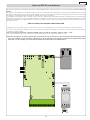 3
3
-
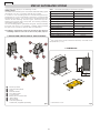 4
4
-
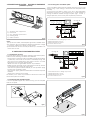 5
5
-
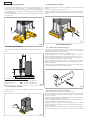 6
6
-
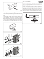 7
7
-
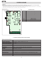 8
8
-
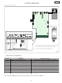 9
9
-
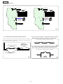 10
10
-
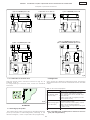 11
11
-
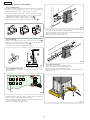 12
12
-
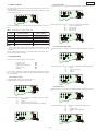 13
13
-
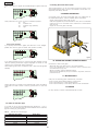 14
14
-
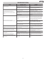 15
15
-
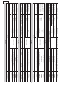 16
16
-
 17
17
-
 18
18
-
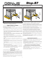 19
19
-
 20
20
-
 21
21
-
 22
22


Genius STEP B7 Instrucciones de operación
- Categoría
- Abridor de puerta
- Tipo
- Instrucciones de operación
en otros idiomas
- français: Genius STEP B7 Mode d'emploi
- italiano: Genius STEP B7 Istruzioni per l'uso
- English: Genius STEP B7 Operating instructions
- Deutsch: Genius STEP B7 Bedienungsanleitung
- Nederlands: Genius STEP B7 Handleiding
Artículos relacionados
-
Genius STEP T Instrucciones de operación
-
-
-
-
-
-
-
-
-

