Sony HT-DDW7500 Guía de inicio rápido
- Categoría
- Receptores AV
- Tipo
- Guía de inicio rápido

4-138-610-11(1)
HT-DDW7500
Quick Setup Guide
Guía de instalación rápida
1: Installing the speakers/
1: Instalación de los altavoces
(1)
Sony Corporation © 2009 Printed in Malaysia
Video components/Componentes de vídeo
2: Connecting the speakers and subwoofers/2: Conexión
de los altavoces y los altavoces potenciadores de graves
3: Connecting other components/
3: Conexión de otros componentes/
CENTER SURROUND BACK
LR
L
R
DIGITAL
(ASSIGNABLE)
DC5V
0.7A MAX
DMPORT
SAT IN
SAT
IN
DVD IN BD IN OUT
AM
Y
P
B
/
C
B
COMPONENT VIDEO
OUT
IN
P
R
/
C
R
DVD
IN
VIDEO 1
IN
MONITOR
OUT
SA-CD
/
CD
/
CD-R
VIDEO 1
IN
TV
TV
AUDIO
IN
VIDEO
IN
SAT
AUDIO
OUT
AUDIO
OUT
VIDEO
OUT
VIDEO
OUT
IN
OPTICAL
AUDIO
IN
VIDEO
IN
SUBWOOFER
MONITOR
AUDIO
IN
VIDEO
IN
BD
SAT
IN
DVD
IN
DCSV
50mA MAX
OUT OUT
OPTICAL COAXIAL
CENTER SURROUND BACK
SURROUND
FRONT
L
L
R
R
LR
HDMIANTENNA
SPEAKERS
SYSTEM CONTROL
SS-CNP7500
L
R
DIGITAL
(ASSIGNABLE)
DC5V
0.7AMAX
DMPORT
SATIN
SAT
IN
DVDIN BDIN OUT
AM
Y
P
B
/
C
B
COMPONENTVIDEO
OUT
IN
P
R
/
C
R
DVD
IN
VIDEO1
IN
MONITOR
OUT
SA-CD
/
CD
/
CD-R
VIDEO1
IN
TV
TV
AUDIO
IN
VIDEO
IN
SAT
AUDIO
OUT
AUDIO
OUT
VIDEO
OUT
VIDEO
OUT
IN
OPTICAL
AUDIO
IN
VIDEO
IN
SUBWOOFER
MONITOR
AUDIO
IN
VIDEO
IN
BD
SAT
IN
DVD
IN
DCSV
50mAMAX
OUT OUT
OPTICAL COAXIAL
CENTER SURROUNDBACK
SURROUND
FRONT
L
L
R
R
LR
HDMIANTENNA
SPEAKERS
SYSTEMCONTROL
CENTER SURROUND BACK
LR
SS-SRP7500 SS-SRP7500
?
/
1
L
R
DIGITAL
(ASSIGNABLE)
DC5V
0.7A MAX
DMPORT
SAT IN
SAT
IN
DVD IN BD IN OUT
AM
Y
P
B
/
C
B
COMPONENT VIDEO
OUT
IN
P
R
/
C
R
DVD
IN
VIDEO 1
IN
MONITOR
OUT
SA-CD
/
CD
/
CD-R
VIDEO 1
IN
TV
TV
AUDIO
IN
VIDEO
IN
SAT
AUDIO
OUT
AUDIO
OUT
VIDEO
OUT
VIDEO
OUT
IN
OPTICAL
AUDIO
IN
VIDEO
IN
SUBWOOFER
MONITOR
AUDIO
IN
VIDEO
IN
BD
SAT
IN
DVD
IN
DCSV
50mA MAX
OUT OUT
OPTICAL COAXIAL
CENTER SURROUND BACK
SURROUND
FRONT
L
L
R
R
LR
HDMIANTENNA
SPEAKERS
SYSTEM CONTROL
FRONT
L
R
SS-MSP7500
L
SS-MSP7500
R
L
R
DIGITAL
(ASSIGNABLE)
DC5V
0.7AMAX
DMPORT
SATIN
SAT
IN
DVDIN BD IN OUT
AM
Y
P
B
/
C
B
COMPONENTVIDEO
OUT
IN
P
R
/
C
R
DVD
IN
VIDEO1
IN
MONITOR
OUT
SA-CD
/
CD
/
CD-R
VIDEO1
IN
TV
TV
AUDIO
IN
VIDEO
IN
SAT
AUDIO
OUT
AUDIO
OUT
VIDEO
OUT
VIDEO
OUT
IN
OPTICAL
AUDIO
IN
VIDEO
IN
SUBWOOFER
MONITOR
AUDIO
IN
VIDEO
IN
BD
SAT
IN
DVD
IN
DCSV
50mAMAX
OUT OUT
OPTICAL COAXIAL
CENTER SURROUND BACK
SURROUND
FRONT
L
L
R
R
LR
HDMIANTENNA
SPEAKERS
SYSTEMCONTROL
SURROUND
LR
SPEAKERS
SS-SRP7500
SS-SRP7500
A
A
English
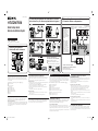
This Quick Setup Guide describes how to connect a DVD player, Blu-ray disc player,
satellite tuner or set-top box, TV, speakers and subwoofers so that you can enjoy
multi channel surround sound. Refer to the operating instructions supplied with the
receiver for details.
The illustrations in the guide designate speakers as
A
through
I
.
A
Front speaker (left)
B
Front speaker (right)
C
Center speaker
D
Surround speaker (left)
E
Surround speaker (right)
F
Surround back speaker (left)
G
Surround back speaker (right)
H
Subwoofer
I
Subwoofer
1: Installing the speakers
The illustration above shows an example of seven speakers and two subwoofers
confi guration. Refer to the operating instructions supplied with the receiver.
About speaker placement
The front speakers, center speaker and subwoofers are magnetically shielded to allow
it to be installed near a TV set. However, as the surround and surround back speakers
are not magnetically shielded, we recommend that you place them slightly further
away from a TV set.
2: Connecting the speakers and subwoofers
The illustrations above show how to connect the speakers. Before you connect the
speakers, check the speaker label on the rear panel of the speakers for the speaker
type.
For details, refer to the operating instructions supplied with the receiver.
About speaker cords
• Use the long speaker cords to connect the surround and surround back speakers and
the short speaker cords to connect the front speakers.
• Connect the cord attached with the “CENTER” labels to the center speaker.
• Use the red and black speaker cords to connect the subwoofers.
Red wire is positive (+) in polarity and should be connected to the positive (+)
speaker terminal.
Connect black wire to the negative (−) speaker terminal.
About speaker jacks
• Connect the
3
jack to the
3
jack of the receiver and connect the
#
jack to the
#
jack of the receiver.
• Refer to the illustration above for details of connecting speaker cords.
3: Connecting other components
This is an example of how to connect this receiver and your components. Refer to
step 3 and 4 of “Getting started” of the operating instructions supplied with this
receiver for details on other connections and other components.
Español
Esta guía de instalación rápida describe cómo conectar un reproductor de DVD, un
reproductor de discos Blu-ray, un sintonizador vía satélite o un decodifi cador, un
televisor, los altavoces y altavoces potenciadores de graves para que pueda disfrutar
del sonido envolvente multicanal. Consulte el manual de instrucciones suministrado
con el receptor para obtener más información.
En las ilustraciones de la guía, los altavoces se identifi can de
A
a
I
.
A Altavoz frontal (izquierdo)
B Altavoz frontal (derecho)
C Altavoz central
D Altavoz de sonido envolvente (izquierdo)
E Altavoz de sonido envolvente (derecho)
F Altavoz de sonido envolvente posterior (izquierdo)
GAltavoz de sonido envolvente posterior (derecho)
H Altavoz potenciador de graves
I Altavoz potenciador de graves
1: Instación de los altavoces
La ilustración anterior muestra un ejemplo de confi guración de un sistema
de seite altavoces y dos altavoces potenciadores de graves. Consulte el
manual de instrucciones suministrado con el receptor.
Sobre la ubicación del altavoz
Los altavoces frontales, el altavoz central y los altavoces potenciadores de graves
están protegidos magnéticamente para que puedan instalarse cerca de un televisor. Sin
embargo, debido a que los altavoces de sonido envolvente y los altavoces de sonido
envolvente posteriores no están protegidos magnéticamente, se recomienda situarlos a
una distancia considerable del televisor.
2: Conexión de los altavoces y los altavoces
potenciadores de graves
Las ilustraciones que aparece más arriba muestra cómo conectar los altavoces. Antes
de conectarlos, compruebe la etiqueta del altavoz situada en el panel posterior de los
mismos para conocer el tipo de altavoz.
Consulte el manual de instrucciones suministrado con el receptor para obtener
información más detallada.
Acerca de los cables de los altavoces
• Utilice los cables largos de conexión de altavoces para conectar los altavoces de
sonido envolvente y los altavoces de sonido envolvente posteriores, y los cables
cortos de conexión de altavoces para conectar el altavoz frontal y el central.
• Conecte el cable con las etiquetas “CENTER” al altavoz central.
• Utilice los cables de altavoz rojo y negro para conectar los altavoces potenciadores
de graves.
El cable rojo corresponde a la polaridad positiva (+) y deberá conectarse al terminal
positivo (+) del altavoz.
Conecte el cable negro al terminal negativo (−) del altavoz.
Acerca de las tomas de los altavoces
• Conecte la toma
3
a la toma
3
del receptor, y conecte la toma
#
a la toma
#
del
receptor.
• Consulte la ilustración anterior para obtener más información sobre cómo conectar
los cables de los altavoces.
3: Conexión de otros componentes
Este es un ejemplo de cómo conectar este receptor a los componentes. Consulte el
paso 3 y 4 de “Procedimientos iniciales” del manual de instrucciones suministrado
con el receptor paras obtener más información sobre cómo realizar otras conexiones y
sobre otros componentes.
DIGITAL
(ASSIGNABLE)
TV
AUDIO
OUT
VIDEO
OUT
IN
OPTICAL
SUBWOOFER
MONITOR
SAT
IN
DVD
IN
DCSV
50mA MAX
OUT OUT
OPTICAL COAXIAL
CENTER SURROUND BACK
SURROUND
FRONT
L
L
R
R
LR
SPEAKERS
SYSTEM CONTROL
L
R
DIGITAL
(ASSIGNABLE)
DC5V
0.7AMAX
DMPORT
SATIN
SAT
IN
DVDIN BDIN OUT
AM
Y
P
B
/
C
B
COMPONENTVIDEO
OUT
IN
P
R
/
C
R
DVD
IN
VIDEO1
IN
MONITOR
OUT
SA-CD
/
CD
/
CD-R
VIDEO1
IN
TV
TV
AUDIO
IN
VIDEO
IN
SAT
AUDIO
OUT
AUDIO
OUT
VIDEO
OUT
VIDEO
OUT
IN
OPTICAL
AUDIO
IN
VIDEO
IN
SUBWOOFER
MONITOR
AUDIO
IN
VIDEO
IN
BD
SAT
IN
DVD
IN
DCSV
50mAMAX
OUT OUT
OPTICAL COAXIAL
CENTER SURROUND BACK
SURROUND
FRONT
L
L
R
R
LR
HDMIANTENNA
SPEAKERS
SYSTEMCONTROL
SUBWOOFER
AUDIO
IN
SYSTEM
CONTROL
SPEAKERS
IN
SUBWOOFER
SS-WP7500
SS-WP7500
SUBWOOFER ONLY FOR SS-WP7500
SYSTEM
CONTROL
SUBWOOFER SPEAKERS
ONLYFOR
STR-KM5500/7500/8500
AUDIO
IN IN
SUBWOOFERONLYFOR SS-WP7500
SUBWOOFER
A
Speaker cord/Cables de los altavoces
B
Monaural audio cord/Cable de audio monoaural
C
System control cable/Cable de control del sistema
10 mm
Note
Be sure to change the
factory setting of the
DVD input button on the
remote so that you can
use the button to control
your DVD player. For
details, see “Changing
button assignments” in the
operating instructions of
the receiver.
Nota
Asegúrese de cambiar
el ajuste de fábrica del
botón de la entrada DVD
del mando a distancia
para que pueda utilizar el
botón para controlar el
reproductor de DVD. Para
más detalles, consulte
“Cambio de función en los
botones” en las manual de
instrucciones del receptor.
DIGITAL
(ASSIGNABLE)
SAT IN DVD I N OUT
AM
TV
IN
SAT
IN
DVD
IN
DCSV
50mA M AX
OUT OUT
OPTICAL COAXIAL
ANTENNA
SYSTEM CONTROL
D
D
D
DIGITAL
OPTICAL
BD IN
HDMI
L
R
DIGITAL
(ASSIGNABLE)
DC5V
0.7AMAX
DMPORT
SATIN
SAT
IN
DVDIN BDIN OUT
AM
Y
P
B
/
C
B
COMPONENTVIDEO
OUT
IN
P
R
/
C
R
DVD
IN
VIDEO1
IN
MONITOR
OUT
SA-CD
/
CD
/
CD-R
VIDEO1
IN
TV
TV
AUDIO
IN
VIDEO
IN
SAT
AUDIO
OUT
AUDIO
OUT
VIDEO
OUT
VIDEO
OUT
IN
OPTICAL
AUDIO
IN
VIDEO
IN
SUBWOOFER
MONITOR
AUDIO
IN
VIDEO
IN
BD
SAT
IN
DVD
IN
DCSV
50mAMAX
OUT OUT
OPTICAL COAXIAL
CENTER SURROUNDBACK
SURROUND
FRONT
L
L
R
R
LR
HDMIANTENNA
SPEAKERS
SYSTEMCONTROL
OPTICAL
D
E
D
HDMI cable/Cable HDMI
E
Optical digital cord/Cable digital óptico
DVD player/
Reproductor de DVD
TV/Televisor
Satellite tuner or Set-top box/
Sintonizador vía satélite o
decodifi cador
Blu-ray disc player/
Reproductor de discos
Blu-ray
A
A
C
B
Cords used for connection (supplied)/
Cables utilizados para la conexión (suministrada)
Cords used for connection (not supplied)/
Cables utilizados para la conexión (no suministrado)
4138610111_DDW7500_GBES_A3.indd 14138610111_DDW7500_GBES_A3.indd 1 3/19/2009 8:44:23 AM3/19/2009 8:44:23 AM

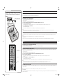
5: Calibrating the speaker settings automatically
/
5: Calibración automática de los ajustes del
altavoz
MULTISTEREOGAME
NIGHTMODE
PHONES
MOVIE
A.F.D.
AUTOCAL MIC
VIDEO
LAUDIOR
VIDEO2 IN
MASTERVOLUMEINPUTSELECTOR
MUSIC
?/1
AUTO CAL MIC
?
/
1
123
46
78
0/10
ENTER
9
SYSTEM STANDBY
TV INPUT
SLEEP
DMPORT
VIDEO1 VIDEO2 BD DVD
2CH A.F.D. MOVIE MUSIC
CLEAR
DISPLAY
TV VOL
MASTER VOL
DVD/BD
MENU
AUTO CAL
D.TUNING
D.SKIP
THEATER
SAT TV SA-CD/CD TUNER
?/1
5
>10
O
RETURN/EXIT
TV
?/1
AV
?/1
TOOLS/
OPTIONS
MENU/HOME
AMP MENUMEMORY
MUTING
Input buttons/
Botones de introducción
AUTO CAL
AMP MENU
English
4: Connect all power cords last
Connect the AC power cord to a wall outlet.
Refer to “Connecting the AC power cord” in the operating instructions supplied with the receiver.
5: Calibrating the speaker settings automatically
You can set up the speakers to obtain the sound you want from all connected speakers automatically by using the Auto Calibration function. The Auto Calibration function will:
• Check the connection between each speaker and the receiver.
• Adjust the speaker level.
•
Measure the distance of each speaker from your listening position.
1 Connect the supplied optimizer microphone to the AUTO CAL MIC jack on the receiver.
2 Set up the optimizer microphone.
Place the optimizer microphone at your listening position.You can also use a stool or tripod so that the optimizer microphone remains at the same height as your ears.
3 Press AMP MENU, then press AUTO CAL.
The Auto Calibration function starts.
For details on the Auto Calibration function, refer to step 7 of "Getting started" of the operating instructions supplied with this receiver.
Notes
• If there are any obstacles in the path between the optimizer microphone and the speakers, the calibration cannot be performed correctly. Remove any obstacles from the measurement area to avoid measurement error.
• The Auto Calibration function cannot detect the subwoofer. Therefore, all subwoofer settings will be maintained.
6: Setting up other components
You should set up each component so that the sound is output from the speakers correctly when you playback a connected component. Refer to the operating instructions supplied with each component.
Note
If no digital signal is input through the COAXIAL or OPTICAL jack on the receiver, “NO INPUT” appears on the display. This is not a malfunction.
After the setting
The receiver is now ready to use. Press the input button on the remote to select the component you want to play back. Refer to the operating instructions supplied with the receiver for details.
Español
4: Conecte todos los cables de alimentación en último lugar
Conecte el cable de alimentación de ca a una toma de pared.
Consulte el apartado “Conexión del cable de alimentación de ca” del manual de instrucciones suministrado con el receptor.
5: Calibración automática de los ajustes del altavoz
Puede instalar los altavoces para obtener automáticamente el sonido que desee a través de todos los altavoces conectados mediante la función de calibración automática. La función de calibración automática:
• Compruebe las conexiones entre cada altavoz y el receptor.
• Ajuste el nivel del altavoz.
• Calculará la distancia existente entre cada altavoz y la posición de escucha.
1 Conecte el micrófono optimizador suministrado a la toma AUTO CAL MIC del receptor.
2 Ajuste el micrófono optimizador.
Coloque el micrófono optimizador en su posición de escucha. Puede utilizar también una banqueta o trípode para que el micrófono optimizador quede a la altura
de los oídos.
3 Pulse AMP MENU y, a continuación, AUTO CAL.
Se iniciará la función de calibración automática.
Para obtener más información sobre la función de calibración automática, consulte el paso 7 de “Procedimientos iniciales” del manual de instrucciones suministrado con el receptor.
Notas
• Si hay obstáculos entre el micrófono optimizador y los altavoces, es posible que la calibración no se lleve a cabo correctamente. Retire los obstáculos de la zona de medición para evitar errores.
• La función de calibración automática no puede detectar el altavoz potenciador de graves. Por lo tanto, todos los ajustes del altavoz potenciador de graves se mantendrán.
6: Confi guración de otros componentes
Es necesario confi gurar cada componente para que el sonido se emita correctamente a través de los altavoces al reproducir un componente conectado. Consulte el manual de instrucciones suministrado con cada
componente en cuestión.
Nota
Si no se recibe ninguna señal digital a través de la tomas COAXIAL u OPTICAL, aparecerá “NO INPUT” en la pantalla. No se trata de un fallo de funcionamiento.
Tras realizar el ajuste
El receptor está listo para utilizarse. Pulse el botón de introducción del mando a distancia para seleccionar el componente que desee reproducir. Consulte el manual de instrucciones suministrado con el receptor
para obtener más información.
Optimizer microphone (supplied)/
Micrófono optimizador (suministrada)
4138610111_DDW7500_GBES_A3.indd 24138610111_DDW7500_GBES_A3.indd 2 3/19/2009 8:44:28 AM3/19/2009 8:44:28 AM
Transcripción de documentos
4-138-610-11(1) HT-DDW7500 2: Connecting the speakers and subwoofers/2: Conexión de los altavoces y los altavoces potenciadores de graves 3: Connecting other components/ 3: Conexión de otros componentes/ Video components/Componentes de vídeo ANTENNA HDMI SAT IN AM Quick Setup Guide Guía de instalación rápida SS-MSP7500 R SS-MSP7500 L ANTENNA DVD IN BD IN DVD IN SAT IN VIDEO 1 IN SAT IN DVD IN VIDEO 1 IN TV MONITOR OUT VIDEO OUT VIDEO IN VIDEO OUT AUDIO IN AUDIO OUT AUDIO IN MONITOR SAT IN IN OPTICAL VIDEO IN VIDEO IN VIDEO OUT VIDEO IN VIDEO OUT AUDIO IN AUDIO IN AUDIO OUT AUDIO IN MONITOR IN TV SAT BD DCSV 50mA MAX OUT OUT DVD IN OPTICAL TV SAT BD DCSV 50mA MAX OUT OUT FRONT SURROUND SURROUND BACK R L R L L R R COAXIAL SA-CD/CD/CD-R FRONT CENTER SURROUND SURROUND BACK R IN OUT DVD IN COAXIAL CENTER SYSTEM CONTROL DC5V 0.7A MAX OUT OPTICAL AUDIO OUT L DMPORT PB/ CB PR/ CR COMPONENT VIDEO SAT IN IN OPTICAL VIDEO IN AUDIO IN IN BD IN SYSTEM CONTROL DC5V 0.7A MAX OUT DIGITAL (ASSIGNABLE) DVD IN DIGITAL (ASSIGNABLE) DMPORT VIDEO IN IN PR / CR OUT COMPONENT VIDEO Y TV MONITOR OUT Y PB/ CB HDMI SAT IN AM L R VIDEO 1 SS-CNP7500 SPEAKERS SUBWOOFER L L AUDIO OUT L R R SA-CD/CD/CD-R VIDEO 1 SPEAKERS SUBWOOFER CENTER SURROUND BACK FRONT R L L R A A Note Be sure to change the factory setting of the DVD input button on the remote so that you can use the button to control your DVD player. For details, see “Changing button assignments” in the operating instructions of the receiver. Satellite tuner or Set-top box/ Sintonizador vía satélite o decodificador D ANTENNA DVD IN VIDEO 1 IN MONITOR OUT Sony Corporation © 2009 Printed in Malaysia ANTENNA HDMI SAT IN AM SAT IN DVD IN VIDEO 1 IN TV MONITOR OUT DVD IN DIGITAL (ASSIGNABLE) ANTENNA SYSTEM CONTROL DC5V 0.7A MAX SAT IN IN OPTICAL VIDEO IN VIDEO IN VIDEO OUT VIDEO IN VIDEO OUT AUDIO IN AUDIO IN AUDIO OUT AUDIO IN MONITOR IN TV SAT BD COAXIAL FRONT SURROUND BACK R L SURROUND R SS-SRP7500 SS-SRP7500 DCSV 50mA MAX OUT OUT DVD IN OPTICAL CENTER COMPONENT VIDEO IN OUT DMPORT Y PB/ CB P R/ CR OUT BD IN L DVD IN VIDEO 1 IN MONITOR OUT TV SPEAKERS SUBWOOFER SAT IN IN OPTICAL VIDEO IN VIDEO OUT VIDEO IN VIDEO OUT AUDIO IN AUDIO IN AUDIO OUT AUDIO IN MONITOR TV SAT BD OPTICAL IN SS-SRP7500 DCSV 50mA MAX OUT OUT FRONT SURROUND SURROUND BACK R OUT OUT DVD IN COAXIAL CENTER COMPONENT VIDEO BD IN SYSTEM CONTROL DC5V 0.7A MAX VIDEO IN IN P R/ CR VIDEO 1 DVD IN DIGITAL (ASSIGNABLE) DMPORT Y PB/ CB R SA-CD/CD/CD-R SS-SRP7500 HDMI SAT IN AM SAT IN L AUDIO OUT L R L R L L AUDIO OUT L R R SA-CD/CD/CD-R 1: Installing the speakers/ 1: Instalación de los altavoces VIDEO 1 SPEAKERS SUBWOOFER SURROUND R CENTER L SURROUND BACK R L A A SPEAKERS Nota Asegúrese de cambiar el ajuste de fábrica del botón de la entrada DVD del mando a distancia para que pueda utilizar el botón para controlar el reproductor de DVD. Para más detalles, consulte “Cambio de función en los botones” en las manual de instrucciones del receptor. TV DVD IN SAT IN IN OPTICAL VIDEO IN VIDEO IN VIDEO OUT VIDEO IN VIDEO OUT AUDIO IN AUDIO IN AUDIO OUT AUDIO IN MONITOR IN TV SAT BD OPTICAL CENTER SURROUND BACK R L SURROUND R L L AUDIO OUT L R R SA-CD/CD/CD-R VIDEO 1 SUBWOOFER SPEAKERS ANTENNA HDMI SAT IN AM TV HDMI SAT IN AM VIDEO 1 IN TV MONITOR OUT DVD IN VIDEO IN SAT IN IN OPTICAL VIDEO OUT VIDEO IN OPTICAL DCSV 50mA MAX OUT OUT DVD IN COAXIAL VIDEO OUT SURROUND BACK L R IN AUDIO IN AUDIO IN TV SAT BD IN AUDIO OUT AUDIO IN SURROUND R OPTICAL AUDIO OUT R TV A B C SPEAKERS SUBWOOFER DIGITAL (ASSIGNABLE) SYSTEM CONTROL SAT IN IN OPTICAL OPTICAL COAXIAL D DIGITAL OPTICAL MONITOR L VIDEO 1 DCSV 50mA MAX OUT OUT DVD IN E L L R SA-CD/CD/CD-R OUT FRONT CENTER OUT OUT SYSTEM CONTROL DC5V 0.7A MAX P R/ CR ?/1 COMPONENT VIDEO BD IN DIGITAL (ASSIGNABLE) DMPORT VIDEO IN BD IN SYSTEM CONTROL SAT IN IN Cords used for connection (supplied)/ Cables utilizados para la conexión (suministrada) SS-WP7500 SS-WP7500 ANTENNA DVD IN SAT IN Y DVD IN DIGITAL (ASSIGNABLE) OPTICAL PB/ CB D DCSV 50mA MAX OUT OUT DVD IN COAXIAL FRONT PR/ CR IN D OUT SYSTEM CONTROL DC5V 0.7A MAX OUT BD IN DIGITAL (ASSIGNABLE) DMPORT PB/ CB COMPONENT VIDEO Blu-ray disc player/ Reproductor de discos Blu-ray HDMI SAT IN AM SAT IN Y (1) DVD player/ Reproductor de DVD C DCSV 50mA MAX OUT OUT DVD IN COAXIAL VIDEO OUT FRONT CENTER SURROUND BACK R L SURROUND R L Speaker cord/Cables de los altavoces Monaural audio cord/Cable de audio monoaural System control cable/Cable de control del sistema TV/Televisor SUBWOOFER ONLY FOR SS-WP7500 L MONITOR AUDIO OUT SUBWOOFER R SUBWOOFER AUDIO IN SPEAKERS 10 mm IN D E SUBWOOFER ONLY FOR SS-WP7500 B SUBWOOFER SUBWOOFER SYSTEM CONTROL SPEAKERS AUDIO IN SUBWOOFER IN SYSTEM CONTROL SPEAKERS ONLY FOR STR-KM5500/7500/8500 English This Quick Setup Guide describes how to connect a DVD player, Blu-ray disc player, satellite tuner or set-top box, TV, speakers and subwoofers so that you can enjoy multi channel surround sound. Refer to the operating instructions supplied with the receiver for details. The illustrations in the guide designate speakers as A through I. A Front speaker (left) B Front speaker (right) C Center speaker D Surround speaker (left) E Surround speaker (right) F Surround back speaker (left) G Surround back speaker (right) H Subwoofer I Subwoofer 2: Connecting the speakers and subwoofers The illustrations above show how to connect the speakers. Before you connect the speakers, check the speaker label on the rear panel of the speakers for the speaker type. For details, refer to the operating instructions supplied with the receiver. About speaker cords • Use the long speaker cords to connect the surround and surround back speakers and the short speaker cords to connect the front speakers. • Connect the cord attached with the “CENTER” labels to the center speaker. • Use the red and black speaker cords to connect the subwoofers. Red wire is positive (+) in polarity and should be connected to the positive (+) speaker terminal. Connect black wire to the negative (−) speaker terminal. About speaker jacks • Connect the 3 jack to the 3 jack of the receiver and connect the # jack to the # jack of the receiver. • Refer to the illustration above for details of connecting speaker cords. Cords used for connection (not supplied)/ Cables utilizados para la conexión (no suministrado) HDMI cable/Cable HDMI Optical digital cord/Cable digital óptico Español Esta guía de instalación rápida describe cómo conectar un reproductor de DVD, un reproductor de discos Blu-ray, un sintonizador vía satélite o un decodificador, un televisor, los altavoces y altavoces potenciadores de graves para que pueda disfrutar del sonido envolvente multicanal. Consulte el manual de instrucciones suministrado con el receptor para obtener más información. En las ilustraciones de la guía, los altavoces se identifican de A a I. A Altavoz frontal (izquierdo) B Altavoz frontal (derecho) C Altavoz central D Altavoz de sonido envolvente (izquierdo) E Altavoz de sonido envolvente (derecho) F Altavoz de sonido envolvente posterior (izquierdo) GAltavoz de sonido envolvente posterior (derecho) H Altavoz potenciador de graves I Altavoz potenciador de graves 1: Installing the speakers The illustration above shows an example of seven speakers and two subwoofers configuration. Refer to the operating instructions supplied with the receiver. About speaker placement The front speakers, center speaker and subwoofers are magnetically shielded to allow it to be installed near a TV set. However, as the surround and surround back speakers are not magnetically shielded, we recommend that you place them slightly further away from a TV set. 4138610111_DDW7500_GBES_A3.indd 1 3: Connecting other components This is an example of how to connect this receiver and your components. Refer to step 3 and 4 of “Getting started” of the operating instructions supplied with this receiver for details on other connections and other components. 1: Instación de los altavoces La ilustración anterior muestra un ejemplo de configuración de un sistema de seite altavoces y dos altavoces potenciadores de graves. Consulte el manual de instrucciones suministrado con el receptor. Sobre la ubicación del altavoz Los altavoces frontales, el altavoz central y los altavoces potenciadores de graves están protegidos magnéticamente para que puedan instalarse cerca de un televisor. Sin embargo, debido a que los altavoces de sonido envolvente y los altavoces de sonido envolvente posteriores no están protegidos magnéticamente, se recomienda situarlos a una distancia considerable del televisor. 2: Conexión de los altavoces y los altavoces potenciadores de graves Las ilustraciones que aparece más arriba muestra cómo conectar los altavoces. Antes de conectarlos, compruebe la etiqueta del altavoz situada en el panel posterior de los mismos para conocer el tipo de altavoz. Consulte el manual de instrucciones suministrado con el receptor para obtener información más detallada. Acerca de los cables de los altavoces • Utilice los cables largos de conexión de altavoces para conectar los altavoces de sonido envolvente y los altavoces de sonido envolvente posteriores, y los cables cortos de conexión de altavoces para conectar el altavoz frontal y el central. • Conecte el cable con las etiquetas “CENTER” al altavoz central. • Utilice los cables de altavoz rojo y negro para conectar los altavoces potenciadores de graves. El cable rojo corresponde a la polaridad positiva (+) y deberá conectarse al terminal positivo (+) del altavoz. Conecte el cable negro al terminal negativo (−) del altavoz. Acerca de las tomas de los altavoces • Conecte la toma 3 a la toma 3 del receptor, y conecte la toma # a la toma # del receptor. • Consulte la ilustración anterior para obtener más información sobre cómo conectar los cables de los altavoces. 3: Conexión de otros componentes Este es un ejemplo de cómo conectar este receptor a los componentes. Consulte el paso 3 y 4 de “Procedimientos iniciales” del manual de instrucciones suministrado con el receptor paras obtener más información sobre cómo realizar otras conexiones y sobre otros componentes. 3/19/2009 8:44:23 AM English 5: Calibrating the speaker settings automatically/ 5: Calibración automática de los ajustes del altavoz ?/1 INPUT SELECTOR MASTER VOLUME NIGHT MODE A.F.D. MOVIE MUSIC GAME Optimizer microphone (supplied)/ Micrófono optimizador (suministrada) MULTI STEREO VIDEO 2 IN AUTO CAL MIC PHONES VIDEO L AUDIO R AUTO CAL MIC 4: Connect all power cords last Connect the AC power cord to a wall outlet. Refer to “Connecting the AC power cord” in the operating instructions supplied with the receiver. 5: Calibrating the speaker settings automatically You can set up the speakers to obtain the sound you want from all connected speakers automatically by using the Auto Calibration function. The Auto Calibration function will: • Check the connection between each speaker and the receiver. • Adjust the speaker level. • Measure the distance of each speaker from your listening position. 1 Connect the supplied optimizer microphone to the AUTO CAL MIC jack on the receiver. 2 Set up the optimizer microphone. Place the optimizer microphone at your listening position.You can also use a stool or tripod so that the optimizer microphone remains at the same height as your ears. 3 Press AMP MENU, then press AUTO CAL. The Auto Calibration function starts. For details on the Auto Calibration function, refer to step 7 of "Getting started" of the operating instructions supplied with this receiver. Notes • If there are any obstacles in the path between the optimizer microphone and the speakers, the calibration cannot be performed correctly. Remove any obstacles from the measurement area to avoid measurement error. • The Auto Calibration function cannot detect the subwoofer. Therefore, all subwoofer settings will be maintained. ?/1 6: Setting up other components You should set up each component so that the sound is output from the speakers correctly when you playback a connected component. Refer to the operating instructions supplied with each component. Note If no digital signal is input through the COAXIAL or OPTICAL jack on the receiver, “NO INPUT” appears on the display. This is not a malfunction. After the setting The receiver is now ready to use. Press the input button on the remote to select the component you want to play back. Refer to the operating instructions supplied with the receiver for details. Español 4: Conecte todos los cables de alimentación en último lugar TV INPUT TV ?/1 SLEEP DMPORT AV ?/1 Conecte el cable de alimentación de ca a una toma de pared. Consulte el apartado “Conexión del cable de alimentación de ca” del manual de instrucciones suministrado con el receptor. ?/1 SYSTEM STANDBY VIDEO1 VIDEO2 BD SAT TV 2CH A.F.D. MOVIE 1 2 3 5: Calibración automática de los ajustes del altavoz DVD SA-CD/CD TUNER Input buttons/ Botones de introducción MUSIC 1 Conecte el micrófono optimizador suministrado a la toma AUTO CAL MIC del receptor. 2 Ajuste el micrófono optimizador. THEATER DVD/BD MENU 4 7 5 8 >10 0/10 6 TOOLS/ OPTIONS 3 Pulse AMP MENU y, a continuación, AUTO CAL. Se iniciará la función de calibración automática. Para obtener más información sobre la función de calibración automática, consulte el paso 7 de “Procedimientos iniciales” del manual de instrucciones suministrado con el receptor. AMP MENU Notas • Si hay obstáculos entre el micrófono optimizador y los altavoces, es posible que la calibración no se lleve a cabo correctamente. Retire los obstáculos de la zona de medición para evitar errores. • La función de calibración automática no puede detectar el altavoz potenciador de graves. Por lo tanto, todos los ajustes del altavoz potenciador de graves se mantendrán. MUTING TV VOL MASTER VOL 6: Configuración de otros componentes Es necesario configurar cada componente para que el sonido se emita correctamente a través de los altavoces al reproducir un componente conectado. Consulte el manual de instrucciones suministrado con cada componente en cuestión. Nota Si no se recibe ninguna señal digital a través de la tomas COAXIAL u OPTICAL, aparecerá “NO INPUT” en la pantalla. No se trata de un fallo de funcionamiento. O RETURN/EXIT AUTO CAL D.SKIP MEMORY AMP MENU ENTER CLEAR DISPLAY Coloque el micrófono optimizador en su posición de escucha. Puede utilizar también una banqueta o trípode para que el micrófono optimizador quede a la altura de los oídos. AUTO CAL D.TUNING 9 Puede instalar los altavoces para obtener automáticamente el sonido que desee a través de todos los altavoces conectados mediante la función de calibración automática. La función de calibración automática: • Compruebe las conexiones entre cada altavoz y el receptor. • Ajuste el nivel del altavoz. • Calculará la distancia existente entre cada altavoz y la posición de escucha. MENU/HOME Tras realizar el ajuste El receptor está listo para utilizarse. Pulse el botón de introducción del mando a distancia para seleccionar el componente que desee reproducir. Consulte el manual de instrucciones suministrado con el receptor para obtener más información. 4138610111_DDW7500_GBES_A3.indd 2 3/19/2009 8:44:28 AM-
 1
1
-
 2
2


Sony HT-DDW7500 Guía de inicio rápido
- Categoría
- Receptores AV
- Tipo
- Guía de inicio rápido
en otros idiomas
- English: Sony HT-DDW7500 Quick start guide
Artículos relacionados
-
Sony HT-DDWG700 Quick Installation Guide
-
-
Sony STR-DN1000 Guía de inicio rápido
-
Sony STR-DH800 Guía de inicio rápido
-
Sony STR-DG820 Guía de instalación
-
Sony STR-DH700 Guía de instalación
-
-
-
Sony STR-DH710 Guía de inicio rápido
-
Sony STR-DG720 Guía de instalación