Metz mecablitz 58 AF-2 digital Nikon Manual de usuario
- Categoría
- Flashes de la cámara
- Tipo
- Manual de usuario

MECABLITZ 58 AF-2 digital
für/for Nikon-Digitalkameras,
incl. CLS-System
Bedienungsanleitung Mode d’emploi
Gebruiksaanwijzing Operating instruction
Manuale istruzioni Manual de instrucciones
709 47 0159.A3 58 AF-2 Nikon 29.07.2011 13:26 Uhr Seite 1

Ķ
1 Sicherheitshinweise . . . . . . . . . . . . . . . . . . . . . . . . . . . . . . . . . . . . . . . . . . 3
2 Dedicated-Blitzfunktionen . . . . . . . . . . . . . . . . . . . . . . . . . . . . . . . . . . . . . . 4
2.1 Aufteilung der Kamera-Gruppen . . . . . . . . . . . . . . . . . . . . . . . . . . . . . . . . . 4
3 Blitzgerät vorbereiten . . . . . . . . . . . . . . . . . . . . . . . . . . . . . . . . . . . . . . . . . 5
3.1 Montage des Blitzgerätes. . . . . . . . . . . . . . . . . . . . . . . . . . . . . . . . . . . . . . . 5
3.2 Stromversorgung. . . . . . . . . . . . . . . . . . . . . . . . . . . . . . . . . . . . . . . . . . . . . 5
3.3 Ein- und Ausschalten des Blitzgerätes . . . . . . . . . . . . . . . . . . . . . . . . . . . . . . 5
3.4 Power Pack P76 (Sonderzubehör). . . . . . . . . . . . . . . . . . . . . . . . . . . . . . . . . 6
3.5 Automatische Geräteabschaltung / Auto - OFF . . . . . . . . . . . . . . . . . . . . . . . 6
4 Displaybeleuchtung . . . . . . . . . . . . . . . . . . . . . . . . . . . . . . . . . . . . . . . . . . 6
5 Blitzbetriebsarten (Mode - Menü). . . . . . . . . . . . . . . . . . . . . . . . . . . . . . . . . 7
5.1 Einstellvorgang für die Blitzbetriebsarten. . . . . . . . . . . . . . . . . . . . . . . . . . . . 7
5.2 TTL-Blitzbetrieb . . . . . . . . . . . . . . . . . . . . . . . . . . . . . . . . . . . . . . . . . . . . . . 7
5.3 TTL-Aufhellblitzbetrieb . . . . . . . . . . . . . . . . . . . . . . . . . . . . . . . . . . . . . . . . . 8
5.4 Automatik-Blitzbetrieb . . . . . . . . . . . . . . . . . . . . . . . . . . . . . . . . . . . . . . . . 10
5.5 Automatik-Aufhellblitzbetrieb. . . . . . . . . . . . . . . . . . . . . . . . . . . . . . . . . . . 10
5.6 Manueller Blitzbetrieb . . . . . . . . . . . . . . . . . . . . . . . . . . . . . . . . . . . . . . . . 10
5.7 Stroboskop-Blitzbetrieb . . . . . . . . . . . . . . . . . . . . . . . . . . . . . . . . . . . . . . . 11
6 Blitzparameter (Parameter-Menü) . . . . . . . . . . . . . . . . . . . . . . . . . . . . . . . 12
6.1 Einstellvorgang für die Blitzparameter. . . . . . . . . . . . . . . . . . . . . . . . . . . . . 12
6.2 Blende (F). . . . . . . . . . . . . . . . . . . . . . . . . . . . . . . . . . . . . . . . . . . . . . . . . 13
6.3 Hauptreflektorposition (Zoom) . . . . . . . . . . . . . . . . . . . . . . . . . . . . . . . . . . 14
6.4 Blitzbelichtungskorrektur (EV) . . . . . . . . . . . . . . . . . . . . . . . . . . . . . . . . . . . 14
6.5 Lichtempfindlichkeit (ISO). . . . . . . . . . . . . . . . . . . . . . . . . . . . . . . . . . . . . . 15
6.6 Manuelle Teillichtleistung (P). . . . . . . . . . . . . . . . . . . . . . . . . . . . . . . . . . . . 15
7 Sonderfunktionen (Select-Menü) . . . . . . . . . . . . . . . . . . . . . . . . . . . . . . . . 16
7.1 Einstellvorgang für die Sonderfunktionen . . . . . . . . . . . . . . . . . . . . . . . . . . 16
7.2 Beep-Funktion (Beep). . . . . . . . . . . . . . . . . . . . . . . . . . . . . . . . . . . . . . . . . 16
7.3 Blitzbelichtungsreihen (FB) . . . . . . . . . . . . . . . . . . . . . . . . . . . . . . . . . . . . . 17
7.4 Extended-Zoom-Betrieb (Zoom Ext). . . . . . . . . . . . . . . . . . . . . . . . . . . . . . . 18
7.5 Aufnahmeformat-Anpassung (Zoom Size) . . . . . . . . . . . . . . . . . . . . . . . . . . 19
7.6 Drahtloser Remote-Betrieb (Remote) . . . . . . . . . . . . . . . . . . . . . . . . . . . . . . 19
7.7 Meter-Feet-Unschaltung (m/ft) . . . . . . . . . . . . . . . . . . . . . . . . . . . . . . . . . . 20
7.8 Zweitreflektor . . . . . . . . . . . . . . . . . . . . . . . . . . . . . . . . . . . . . . . . . . . . . . 20
7.9 Einstelllicht (ML) „Modelling Light“ . . . . . . . . . . . . . . . . . . . . . . . . . . . . . . . 21
7.10 Automatische Geräteabschaltung (Standby) . . . . . . . . . . . . . . . . . . . . . . . . 21
7.11 Tastatur-Verriegelung (KEYLOCK) . . . . . . . . . . . . . . . . . . . . . . . . . . . . . . . . 22
7.12 AF-BEAM (AF-Hilfslicht). . . . . . . . . . . . . . . . . . . . . . . . . . . . . . . . . . . . . . . 23
8 Motor-Zoom-Reflektor . . . . . . . . . . . . . . . . . . . . . . . . . . . . . . . . . . . . . . . 23
9 Weitwinkelstreuscheibe. . . . . . . . . . . . . . . . . . . . . . . . . . . . . . . . . . . . . . . 24
10 Blitztechniken. . . . . . . . . . . . . . . . . . . . . . . . . . . . . . . . . . . . . . . . . . . . . . 24
10.1 Indirektes Blitzen . . . . . . . . . . . . . . . . . . . . . . . . . . . . . . . . . . . . . . . . . . . . 24
10.2 Indirektes Blitzen mit Reflektorkarte. . . . . . . . . . . . . . . . . . . . . . . . . . . . . . . 24
10.3 Indirektes Blitzen mit Zweitreflektor . . . . . . . . . . . . . . . . . . . . . . . . . . . . . . . 25
10.4 Nahaufnahmen / Makroaufnahmen. . . . . . . . . . . . . . . . . . . . . . . . . . . . . . 25
10.5 Manuelle Blitzbelichtungskorrekturen . . . . . . . . . . . . . . . . . . . . . . . . . . . . . 25
11 Blitzbereitschaftsanzeige. . . . . . . . . . . . . . . . . . . . . . . . . . . . . . . . . . . . . . 26
12 Automatische Blitzsynchronzeitsteuerung. . . . . . . . . . . . . . . . . . . . . . . . . . 26
13 Belichtungskontrollanzeige . . . . . . . . . . . . . . . . . . . . . . . . . . . . . . . . . . . . 26
14 Unterbelichtungsanzeige im TTL-Blitzbetrieb. . . . . . . . . . . . . . . . . . . . . . . . 26
15 Anzeigen im Kamerasucher . . . . . . . . . . . . . . . . . . . . . . . . . . . . . . . . . . . 27
16 Reichweitenanzeige . . . . . . . . . . . . . . . . . . . . . . . . . . . . . . . . . . . . . . . . . 27
16.1 Automatische Anpassung der Reichweitenanzeige. . . . . . . . . . . . . . . . . . . . 27
16.2 Manuelle Anpassung der Reichweitenanzeige . . . . . . . . . . . . . . . . . . . . . . . 28
16.3 Error-Anzeige „FEE“ im LC-Display des Blitzgerätes. . . . . . . . . . . . . . . . . . . 28
16.4 Leitzahlanzeige bei Objektiven ohne CPU . . . . . . . . . . . . . . . . . . . . . . . . . . 28
17 Blitzbelichtungs-Messwertspeicher. . . . . . . . . . . . . . . . . . . . . . . . . . . . . . . 28
18 Blitzsynchronisation . . . . . . . . . . . . . . . . . . . . . . . . . . . . . . . . . . . . . . . . . 29
18.1 Normalsynchronisation . . . . . . . . . . . . . . . . . . . . . . . . . . . . . . . . . . . . . . . 29
18.2 Synchronisation auf den 2.Verschlussvorhang (REAR-Betrieb) . . . . . . . . . . . . 29
18.3 Langzeitsynchronisation (SLOW) . . . . . . . . . . . . . . . . . . . . . . . . . . . . . . . . 29
18.4 Automatische FP-Kurzzeitsynchronisation . . . . . . . . . . . . . . . . . . . . . . . . . . 29
19 Vorblitzfunktion gegen „Rote-Augen-Effekt“ . . . . . . . . . . . . . . . . . . . . . . . 30
20 Mehrzonen-AF-Meßblitz . . . . . . . . . . . . . . . . . . . . . . . . . . . . . . . . . . . . . . 30
21 Drahtloser Remote-Betrieb . . . . . . . . . . . . . . . . . . . . . . . . . . . . . . . . . . . . 31
21.1 Einstellen und Ausschalten des Remote-Betriebes . . . . . . . . . . . . . . . . . . . . . 31
21.2 Einstellungen am Master-Blitzgerät . . . . . . . . . . . . . . . . . . . . . . . . . . . . . . . 32
21.3 Einstellung am Slave-Blitzgerät. . . . . . . . . . . . . . . . . . . . . . . . . . . . . . . . . . 32
21.4 Prüfen des Remote-Betriebes . . . . . . . . . . . . . . . . . . . . . . . . . . . . . . . . . . . 32
21.5 SERVO-Betrieb . . . . . . . . . . . . . . . . . . . . . . . . . . . . . . . . . . . . . . . . . . . . . 33
22 Wartung und Pflege . . . . . . . . . . . . . . . . . . . . . . . . . . . . . . . . . . . . . . . . . 34
22.1 Firmware-Update . . . . . . . . . . . . . . . . . . . . . . . . . . . . . . . . . . . . . . . . . . . 34
22.2 Reset . . . . . . . . . . . . . . . . . . . . . . . . . . . . . . . . . . . . . . . . . . . . . . . . . . . . 34
22.3 Formieren des Blitzkondensators. . . . . . . . . . . . . . . . . . . . . . . . . . . . . . . . . 34
23 Hilfe bei Störungen. . . . . . . . . . . . . . . . . . . . . . . . . . . . . . . . . . . . . . . . . . 34
24 Technische Daten . . . . . . . . . . . . . . . . . . . . . . . . . . . . . . . . . . . . . . . . . . . 37
25 Sonderzubehör. . . . . . . . . . . . . . . . . . . . . . . . . . . . . . . . . . . . . . . . . . . . . 38
Garantiebestimmungen . . . . . . . . . . . . . . . . . . . . . . . . . . . . . . . . . . . . . . . 39
Tabelle 3: Leitzahlen bei maximaler Lichtleistung (P 1/1). . . . . . . . . . . . . . . . . . . 222
Tabelle 4: Blitzleuchtzahlen in den Teillichtleistungsstufen. . . . . . . . . . . . . . . . . . . 223
Tabelle 5: Kameraverschlusszeiten im Stroboskop-Betrieb . . . . . . . . . . . . . . . . . . 224
Tabelle 6: Blitzfolgezeiten und Blitzanzahl bei den versch. Batterietypen. . . . . . . . 225
Tabelle 7:Maximale Leitzahlen im HSS-Betrieb . . . . . . . . . . . . . . . . . . . . . . . . . . 225
2
709 47 0159.A3 58 AF-2 Nikon 29.07.2011 13:26 Uhr Seite 2

Vorwort
Vielen Dank, dass Sie sich für ein Metz Produkt entschieden haben.
Wir freuen uns, Sie als Kunde begrüßen zu dürfen.
Natürlich können Sie es kaum erwarten, das Blitzgerät in Betrieb zu nehmen.
Es lohnt sich aber, die Bedienungsanleitung zu lesen, denn nur so lernen Sie, mit
dem Gerät problemlos umzugehen.
Dieses Blitzgerät ist geeignet für:
• Analoge und digitale Nikon-Kameras mit TTL-, D-TTL und i-TTL-Blitzsteuerung.
• Digitale Fuji-SLR-Kameras „Fuji FinePix S2Pro“, „Fuji FinePix S3Pro“
Für Kameras anderer Hersteller ist das Blitzgerät nicht geeignet !
Schlagen Sie bitte auch die Bildseite des Umschlages am Ende der
Anleitung auf.
1 Sicherheitshinweise
• Das Blitzgerät ist ausschließlich zur Verwendung im fotografischen Bereich
vorgesehen und zugelassen!
• In Umgebung von entflammbaren Gasen oder Flüssigkeiten (Benzin,
Lösungsmittel etc.) darf das Blitzgerät keinesfalls ausgelöst werden!
EXPLOSIONSGEFAHR!
• Auto-, Bus-, Fahrrad-, Motorrad- oder Zugfahrer etc. niemals während der
Fahrt mit einem Blitzgerät fotografieren. Durch die Blendung kann der
Fahrer einen Unfall verursachen!
• Lösen Sie in unmittelbarer Nähe der Augen keinesfalls einen Blitz aus! Ein
Blitzlicht direkt vor den Augen von Personen und Tieren kann zur
Netzhautschädigung führen und schwere Sehstörungen verursachen - bis
hin zur Erblindung!
• Nur die in der Bedienungsanleitung bezeichneten und zugelassenen
Stromquellen verwenden!
• Batterien/Akkus nicht übermäßiger Wärme wie Sonnenschein, Feuer oder
dergleichen aussetzen!
☞
• Verbrauchte Batterien/Akkus nicht ins Feuer werfen!
•
Aus verbrauchten Batterien kann Lauge austreten, was zur Beschädigung der
Kontakte führt. Verbrauchte Batterien deshalb immer aus dem Gerät entnehmen.
• Trockenbatterien dürfen nicht geladen werden.
•
Blitz- und Ladegerät nicht Tropf- und Spritzwasser (z.B. Regen) aussetzen!
• Schützen Sie Ihr Blitzgerät vor großer Hitze und hoher Luftfeuchtigkeit!
Blitzgerät nicht im Handschuhfach des Autos aufbewahren!
• Beim Auslösen eines Blitzes darf sich kein lichtundurchlässiges Material
unmittelbar vor oder direkt auf der Reflektorscheibe befinden. Die Re-
flektorscheibe darf nicht verunreinigt sein. Bei Nichtbeachtung kann es,
durch die hohe Energie des Blitzlichtes, zu Verbrennungen des Materials
bzw. der Reflektorscheibe führen.
• Nach mehrfachem Blitzen nicht die Reflektorscheibe berühren.
Verbrennungsgefahr!
• Blitzgerät nicht zerlegen! HOCHSPANNUNG! Im Geräteinneren befinden
sich keine Bauteile, die von einem Laien repariert werden können.
• Bei Serienblitzaufnahmen mit voller Lichtleistung und kurzen Blitzfolgezeiten
ist darauf zu achten, dass nach jeweils 15 Blitzen eine Pause von minde-
stens 10 Minuten eingehalten wird. Somit vermeiden Sie eine Überlastung
des Gerätes.
•
Bei Serienblitzaufnahmen mit voller Lichtleistung und kurzen Blitzfolgezeiten
wärmt sich die Streuscheibe bei Zoompositionen von 35mm und weniger durch
die hohe Lichtenergie stark auf. Das Blitzgerät schützt sich gegen Überhitzung,
indem die Blitzfolgezeit automatisch verlängert wird.
• Das Blitzgerät darf nur dann zusammen mit einem in die Kamera eingebau-
ten Blitzgerät verwendet werden, wenn dieses vollständig ausgeklappt wer-
den kann!
• Bei raschem Temperaturwechsel kann Feuchtigkeitsbeschlag auftreten.
Gerät akklimatisieren lassen!
• Keine schadhaften Batterien oder Akkus verwenden!
3
Ķ
709 47 0159.A3 58 AF-2 Nikon 29.07.2011 13:26 Uhr Seite 3

Ķ
4
2 Dedicated-Blitzfunktionen
Die Dedicated-Blitzfunktionen sind speziell auf das Kamerasystem abge-
stimmte Blitzfunktionen. In Abhängigkeit vom Kameratyp werden dabei ver-
schiedene Blitzfunktionen unterstützt.
2.1 Aufteilung der Kamera-Gruppen
Die Nikon-Kameras können hinsichtlich der Dedicated-Blitzfunktionen in
folgende Gruppen aufgeteilt werden:
Kameras aus Gruppe A Kameras ohne digitale Datenübertragung
zum Blitzgerät
z.B. Nikon F601, F601M, F60, F50, FM-3A
Digitale Kompaktkameras “Nikon - Coolpix”
Kameras aus Gruppe B Kameras mit digitaler Datenübertragung
zum Blitzgerät
z.B. Nikon F4, F4s, F801, F801s
Kameras aus Gruppe C Kameras mit digitaler Datenübertragung zum
Blitzgerät und 3D-Multisensor-Aufhellblitzbetrieb
z.B. Nikon F5, F100, F90X, F90, F80, F 75, F70,
Fuji FinePix S2Pro
Kameras aus Gruppe D Digitale Nikon-Spiegelreflexkameras mit
D-TTL-Blitzbetrieb (ohne CLS Unterstützung)
z.B. D1, D1x, D1H, D100, Fuji FinePix S3Pro
Kameras aus Gruppe E Digitale Nikon-Spiegelreflexkameras
mit i-TTL-Blitzbetrieb (CLS kompatible Kameras)
z.B. D2Hs, D2x, D2xs, D3, D3x, D40, D40x,
D50, D60, D70, D70S, D80, D90, D200, D300,
D700, D3000, D5000, F6, Fuji FinePix S5Pro,
Coolpix 8400, 8800, P5000, P5100
Tabelle 1
Kamera-Gruppe
Dedicated Blitzfunktionen
AB C D E
•••••Blitzbereitschaftsanzeige im Kamerasucher / Kameradisplay
•••••
Belichtungskontrollanzeige im Kamerasucher / Kameradisplay
• • • Unterbelichtungsanzeige EV im LC-Display des Blitzgerätes
•••••Automatische Blitzsynchronzeitsteuerung
• • • TTL-Blitzsteuerung (Standard-TTL ohne Messvorblitz)
•••••Automatische Aufhellblitzsteuerung
• • Matrixgesteuerter TTL-Aufhellblitzbetrieb
• 3D-Multisensor-Aufhellblitzbetrieb
• D-TTL-Blitzbetrieb und D-TTL-3D-Blitzbetrieb
• i-TTL-Blitzbetrieb und i-TTL-BL-Blitzbetrieb
• Blitzbelichtungs-Messwertspeicher bei i-TTL und i-TTL-BL
••••Manuelle TTL-/D-TTL-/i-TTL-Blitzbelichtungskorrektur
• • • Synchronisation auf den 1. oder 2.Verschlussvorhang (REAR)
•
Automatische FP-Kurzzeitsynchronisation bei i-TTL, i-TTL-BL und M
••••Automatische Motor-Zoom-Steuerung
••••Extended-Zoom-Betrieb
•••••Automatische AF-Messblitzsteuerung
••••Automatische Blitzreichweitenanzeige
•••••Programmblitzautomatik
• • • Vorblitzfunktion zur Reduzierung des Rote-Augen-Effektes
• • • Zündungssteuerung / Auto-Flash
•
Drahtloser Remote-Blitzbetrieb (Nikon Advanced Wireless Lighting)
•••••Wake-Up Funktion für das Blitzgerät
• Zoom Size-Funktion (abhängig von der Kamera)
Im Rahmen dieser Bedienungsanleitung ist es nicht möglich, alle Ka-
meratypen mit den einzelnen Blitzfunktionen detailliert zu beschrei-
ben. Beachten Sie deshalb die Hinweise zum Blitzbetrieb in der
Bedienungsanleitung Ihrer Kamera, welche Blitzfunktionen von Ihrem
Kameratyp unterstützt werden bzw. an der Kamera selbst eingestellt
werden müssen! Bei der Verwendung von Objektiven ohne CPU (z.B.
Objektive ohne Autofokus) ergeben sich zum Teil Einschränkungen!
☞
Tabelle 2
709 47 0159.A3 58 AF-2 Nikon 29.07.2011 13:26 Uhr Seite 4

3 Blitzgerät vorbereiten
3.1 Montage des Blitzgerätes
Blitzgerät auf die Kamera montieren
Kamera und Blitzgerät vor der Montage oder Demontage ausschalten.
•
Rändelmutter
bis zum Anschlag gegen das Blitzgerät drehen. Der Sicherungs-
stift im Fuß ist jetzt vollkommen im Gehäuse des Blitzgerätes versenkt.
• Blitzgerät mit dem Anschlussfuß bis zum Anschlag in den Zubehörschuh der
Kamera schieben.
•
Rändelmutter
bis zum Anschlag gegen das Kameragehäuse drehen und das
Blitzgerät festklemmen. Bei Kameragehäusen, die kein Sicherungsloch aufwei-
sen, versenkt sich der federgelagerte Sicherungsstift im Gehäuse des
Blitzgerätes, damit die Oberfläche nicht beschädigt wird.
Blitzgerät von der Kamera abnehmen
Kamera und Blitzgerät vor der Montage oder Demontage ausschalten.
• Rändelmutter bis zum Anschlag gegen das Blitzgerät drehen.
• Blitzgerät aus dem Zubehörschuh der Kamera herausziehen.
3.2 Stromversorgung
Batterien- bzw. Akkuauswahl
Das Blitzgerät kann wahlweise betrieben werden mit hochwertigen:
•
4 NC-Akkus 1,2 V, Typ IEC KR (AA / Mignon), sie bieten sehr kurze
Blitzfolgezeiten und sparsamen Betrieb, da sie wiederaufladbar sind.
•
4 Nickel-Metall-Hydrid Akkus 1,2 V, Typ HR6 (AA / Mignon), deutlich höhere
Kapazität als NC-Akku und weniger umweltschädlich, da cadmiumfrei.
• 4 Alkali-Mangan-Trockenbatterien 1,5 V, Typ IEC LR6 (AA / Mignon), war-
tungsfreie Stromquelle für gemäßigte Leistungsanforderungen.
• 4 Lithium-Batterien 1,5 V, Typ IEC FR6 (AA / Mignon), wartungsfreie Strom-
quelle mit hoher Kapazität und geringer Selbstentladung.
☞
☞
• Power Pack P76 mit Verbindungskabel V58-50 (Sonderzubehör)
Wenn Sie das Blitzgerät längere Zeit nicht benutzen, entfernen Sie bitte
die Batterien aus dem Gerät.
Batterien austauschen
Die Akkus/Batterien sind leer bzw. verbraucht, wenn die Blitzfolgezeit (Zeit vom
Auslösen eines Blitzes mit voller Lichtleistung, z.B. bei M, bis zum erneuten
Aufleuchten der Blitzbereitschaftsanzeige ) über 60 Sekunden ansteigt.
• Blitzgerät mit dem Hauptschalter ausschalten.
• Den Batteriefachdeckel nach unten schieben und aufklappen.
• Batterien oder Akkus in Längsrichtung entsprechend den angegebenen
Batteriesymbolen einsetzen und Batteriefachdeckel schließen.
Achten Sie beim Einsetzen der Batterien bzw. Akkus auf die richtige
Polarität gemäß den Symbolen im Batteriefach. Vertauschte Pole können
zur Zerstörung des Gerätes führen! Explosionsgefahr bei unsachgemä-
ßem Auswechseln der Batterien. Ersetzen Sie immer alle Batterien durch
gleiche, hochwertige Batterien eines Herstellertyps mit gleicher
Kapazität! Verbrauchte Batterien bzw. Akkus gehören nicht in den
Hausmüll! Leisten Sie einen Beitrag zum Umweltschutz und geben Sie
verbrauchte Batterien bzw. Akkus bei entsprechenden Sammelstellen ab!
3.3 Ein- und Ausschalten des Blitzgerätes
Das Blitzgerät wird mit dem Hauptschalter einge-
schaltet. In der Stellung „ON“ ist das Blitzgerät einge-
schaltet.
Zum Ausschalten den Hauptschalter in die linke
Position schieben.
Wird das Blitzgerät längere Zeit nicht gebraucht, so empfehlen wir:
Blitzgerät mit dem Hauptschalter ausschalten und die Stromquellen
(Batterien, Akkus) entnehmen.
☞
☞
☞
5
Ķ
✴
709 47 0159.A3 58 AF-2 Nikon 29.07.2011 13:26 Uhr Seite 5

3.4 Power Pack P76 (Sonderzubehör)
Wenn die Blitzanzahl und die Blitzfolgezeiten für Ihren Anwendungsfall nicht aus-
reichen, kann das Blitzgerät von einem Power Pack P76 (Sonderzubehör) mit
Energie versorgt werden. Das Power Pack P76 wird mit dem Verbindungskabel
V58-50 (Sonderzubehör) über den Anschluss an das Blitzgerät angeschlossen.
Eingelegte Batterien / Akkus dürfen nicht im Blitzgerät verbleiben.
Zum Anschließen des Power Pack P76 bzw. des Verbindungskabels V58-50
(Zubehör) am Blitzgerät muss der Hauptschalter des Blitzgerätes in die linke
Position (AUS bzw. OFF) geschaltet werden.
Das Blitzgerät wird dann mit dem Schalter am Power Pack P76 ein- bzw. ausge-
schaltet (siehe Bedienungsanleitung des Power Pack).
Um das Blitzgerät beim Betrieb mit Power Pack vor einer thermischen
Überlastung zu schützen wird bei extremer Beanspruchung durch eine
Überwachungsschaltung die Blitzfolgezeit entsprechend verlängert!
Vor dem Anschließen und Abziehen des Verbindungskabels bzw. des
Power Pack das Blitzgerät und das Power Pack ausschalten!
3.5 Automatische Geräteabschaltung / Auto - OFF
Werksseitig ist das Blitzgerät so eingestellt, dass es ca. 10 Minuten -
• nach dem Einschalten,
• nach dem Auslösen eines Blitzes,
• nach dem Antippen des Kameraauslösers,
• nach dem Ausschalten des Kamerabelichtungsmesssystems...
...in den Standby-Betrieb schaltet (Auto-OFF), um Energie zu sparen und die
Stromquellen vor unbeabsichtigtem Entladen zu schützen. Die Blitzbereitschafts-
anzeige und die Anzeigen auf dem LC-Display verlöschen.
Die zuletzt benutzte Betriebseinstellung bleibt nach der automatischen Abschaltung
erhalten und steht nach dem Einschalten sofort wieder zur Verfügung. Das
Blitzgerät wird durch Drücken einer beliebigen Taste bzw. durch Antippen des
Kameraauslösers (Wake-Up-Funktion) wieder eingeschaltet.
☞
☞
Wenn das Blitzgerät längere Zeit nicht benötigt wird, sollte das Gerät
grundsätzlich immer mit dem Hauptschalter ausgeschaltet werden!
Bei Bedarf kann die automatische Geräteabschaltung bereits nach 1 Minute
erfolgen oder ausgeschaltet werden (siehe Kap. 7.10).
4 Displaybeleuchtung
Bei jedem Tastendruck am Blitzgerät wird für ca. 10 Sek. die
Displaybeleuchtung des Blitzgerätes aktiviert. Beim Auslösen eines Blitzes durch
die Kamera oder durch den Handauslöser am Blitzgerät wird die
Displaybeleuchtung abgeschaltet.
Bei einigen Kameratypen aus Gruppe C, D und E wird beim Einschalten der
Displaybeleuchtung des Blitzgerätes gleichzeitig auch die der Kamera einge-
schaltet. Beim Einschalten der Displaybeleuchtung der Kamera wird dann auch
die des Blitzgerätes aktiviert.
☞
6
Ķ
709 47 0159.A3 58 AF-2 Nikon 29.07.2011 13:26 Uhr Seite 6

5 Blitzbetriebsarten (Mode - Menü)
Das Blitzgerät unterstützt die Blitzbetriebsarten , Automatik , Manuell
und Stroboskop .
In Abhängigkeit vom Kameratyp werden zusätzliche Blitzbetriebsarten
unterstützt. Diese Blitzbetriebsarten können nach einem Datenaustausch
mit der Kamera im Mode-Menü ausgewählt bzw. aktiviert werden.
5.1 Einstellvorgang für die Blitzbetriebsarten
• Taste so oft drücken, bis im Display „Mode“ angezeigt wird.
Folgende Betriebsarten stehen zur Auswahl:
TTL-Blitzbetrieb bzw. D-TTL / i-TTL
BL TTL-Aufhellblitzbetriebsarten bzw. D-TTL-3D / i-TTL-BL
(abhängig vom Kameratyp)
Automatik-Blitzbetrieb
Manueller Blitzbetrieb
Stroboskop-Blitzbetrieb
• Mit den Tasten und die gewünschte
Blitzbetriebsart ( , Automatik , Manuell ,
usw.) einstellen. Die ausgewählte Blitzbetriebsart
wird dabei von einem Balken hinterlegt.
Die Einstellung wird sofort wirksam.
• Die Taste drücken. Das Display schaltet auf die normale Anzeige zurück.
Wenn die Taste nicht gedrückt wird, schaltet das Display nach ca. 5 s
automatisch auf die normale Anzeige zurück.
MATTL
M
A
TTL
TTL
Mode
☞
M
ATTL
Blitzbetrieb mit Kameras aus Gruppe A (siehe Tabelle 1)
Die Blitzparameter für ISO, Blende und Objektiv-Brennweite bzw.
Reflektorposition müssen von Hand eingestellt werden (siehe Kap. 6).
Die Reichweitenanzeige im Display erfolgt gemäß den eingestellten
Blitzparametern.
Blitzbetrieb mit Kameras aus Gruppe B, C, D und E (siehe Tabelle 1)
Die Blitzparameter für ISO, Blende und Objektiv-Brennweite bzw.
Reflektorposition werden automatisch eingestellt, wenn die Kamera die entspre-
chenden Daten an das Blitzgerät überträgt.
Die Reichweitenanzeige im Display erfolgt gemäß den von der Kamera übertra-
genen Blitzparametern.
Falls die Kamera einen oder mehrere Blitzparameter nicht überträgt,
müssen diese von Hand am Blitzgerät eingestellt werden (siehe Kap. 6).
5.2 TTL-Blitzbetrieb
Im TTL-Blitzbetrieb erreichen Sie auf einfache Art sehr gute Blitzlichtaufnahmen.
In dieser Blitzbetriebsart wird die Belichtungsmessung von einem Sensor in der
Kamera vorgenommen. Dieser misst das durchs Objektiv (TTL = „T
rough The
L
ens“) einfallende Licht. Beim Erreichen der erforderlichen Lichtmenge sendet
die Kameraelektronik ein Stopp-Signal an das Blitzgerät und die Lichtabstrah-
lung wird sofort unterbrochen. Der Vorteil dieses Blitzbetriebes liegt darin, dass
alle Faktoren, welche die Belichtung beeinflussen (Aufnahmefilter, Blenden- und
Brennweitenänderungen bei Zoom-Objektiven, Auszugsverlängerungen für
Nahaufnahmen usw.), automatisch bei der Regelung des Blitzlichtes berücksich-
tigt werden.
Der TTL-Blitzbetrieb wird von allen Kamerabetriebsarten (z.B. Programm „P“,
Zeitautomatik „A“, Blendenautomatik „S“, Vari- bzw. Motiv-Programme,
Manuell „M“ usw.) unterstützt.
☞
7
Ķ
Mode TTL BL
A
M
Set
A
☛
709 47 0159.A3 58 AF-2 Nikon 29.07.2011 13:26 Uhr Seite 7

Einstellvorgang:
• Taste so oft drücken, bis im Display „Mode“
angezeigt wird.
• Mit den Tasten und die Blitzbetriebsart
einstellen. Die ausgewählte Blitzbetriebsart wird
dabei von einem Balken hinterlegt.
Die Einstellung wird sofort wirksam.
• Die Taste drücken. Das Display schaltet auf die
normale Anzeige zurück. Wenn die Taste nicht
gedrückt wird, schaltet das Display nach ca. 5 s
automatisch auf die normale Anzeige zurück.
Der Standard-TTL-Blitzbetrieb wird nur von
Kameras aus Gruppe A, B und C unterstützt!
D-TTL- / i-TTL Blitzbetrieb
D-TTL- und i-TTL Blitzbetrieb sind Weiterentwicklungen des
Standard TTL–Blitzbetriebes analoger Kameras. Diese werden von Kameras aus
Gruppe D bzw. E unterstützt (siehe Tabelle1). Bei der Aufnahme werden vor
der eigentlichen Belichtung mehrere fast unsichtbarer Messvorblitze des
Blitzgerätes abgegeben. Das reflektierte Licht der Messvorblitze wird von der
Kamera ausgewertet. Entsprechend der Auswertung wird die nachfolgende
Blitzbelichtung von der Kamera an die Aufnahmesituation angepasst (siehe
Kamerabedienungsanleitung).
Je nach Kameratyp wird vom Blitzgerät bei der Einstellung der Blitzbetriebsart
TTL im „Mode-Menü“ automatisch der Standard-TTL–, D–TTL– bzw.
i–TTL–Blitzbetrieb aktiviert (siehe Tabelle 1 und Tabelle 2)!
Nach dem Speichern wird im Display des Blitzgerätes für den D–TTL-, bzw.
i–TTL–Blitzbetrieb angezeigt.
TTL
☞
TTL
Mode
Einstellvorgang:
• Taste so oft drücken, bis im Display „Mode“
angezeigt wird.
• Mit den Tasten und die Blitzbetriebsart
einstellen. Die ausgewählte Blitzbetriebsart
wird dabei von einem Balken hinterlegt.
Die Einstellung wird sofort wirksam.
• Die Taste drücken. Das Display schaltet auf die
normale Anzeige zurück. Wenn die Taste nicht
gedrückt wird, schaltet das Display nach ca. 5 s
automatisch auf die normale Anzeige zurück.
Bei einer korrekt belichteten Aufnahme erfolgt für ca.
3s die Belichtungskontrollanzeige „o.k.“ (siehe Kap.
13).
Zum Testen der TTL-Funktion muss sich bei
Analog-Kameras ein Film in der Kamera befinden! Beachten Sie, ob es
für Ihre Kamera Einschränkungen hinsichtlich der Filmempfindlichkeit
bzw. ISO-Zahl (z.B. maximal ISO 1000) für den TTL-Blitzbetrieb gibt
(siehe Kamerabedienungsanleitung) !
5.3 TTL-Aufhellblitzbetrieb
Mit dem TTL-Aufhellblitzbetrieb BL können Sie bei Tageslicht lästige Schatten
beseitigen und bei Gegenlichtaufnahmen eine ausgewogene Belichtung zwi-
schen Motiv und Bildhintergrund erreichen. Ein computergesteuertes Messsystem
der Kamera sorgt für die geeignete Kombination von Verschlusszeit,
Arbeitsblende und Blitzleistung. Bei Kameras aus Gruppe C, D und E (siehe
Tabelle 1) geht bei der Verwendung von „D-AF-Nikkor-Objektiven“ zusätzlich
die Entfernung zum Motiv in die Bestimmung der optimalen Blitzleistung ein.
TTL
☞
TTL
Mode
8
Ķ
Mode Para Sel
F 5.6
AZoom 28
7.7 m ISO 100
TTL
Mode
A
A
Set
TTL
☛
Mode
A
A
Set
TTL
☛
☛
Mode Para Sel
F5.6
AZoom 35
12 m ISO 200
TTL
✴
709 47 0159.A3 58 AF-2 Nikon 29.07.2011 13:26 Uhr Seite 8

Einstellvorgang:
• Taste so oft drücken, bis im Display „Mode“
angezeigt wird.
• Mit den Tasten und die Blitzbetriebs-
art BL einstellen. Die ausgewählte
Blitzbetriebsart wird dabei von einem Balken hinter-
legt.
Die Einstellung wird sofort wirksam.
• Die Taste drücken. Das Display schaltet auf die
normale Anzeige zurück. Wenn die Taste nicht
gedrückt wird, schaltet das Display nach ca. 5 s
automatisch auf die normale Anzeige zurück.
Bei einer korrekt belichteten Aufnahme erfolgt für ca.
3s die Belichtungskontroll-anzeige „o.k.“ (siehe
Kap. 13).
Achten Sie darauf, dass die Gegenlichtquelle nicht direkt ins Objektiv
scheint. Das Messsystem der Kamera würde dadurch getäuscht werden!
Je nach Kameratyp wird nach Einstellung der Blitzbetriebsart BL vom
Blitzgerät automatisch der geeignete Aufhellblitzbetrieb aktiviert:
Kameras aus Gruppe A:
• Automatischer Aufhellblitzbetrieb bzw. Matrixgesteuerter Aufhellblitzbetrieb.
• Die Einstellung erfolgt an der Kamera von Hand oder automatisch
(siehe Kamerabedienungsanleitung)
• Anzeige am Blitzgerät:
• Am Blitzgerät erfolgt keine zusätzliche Einstellung bzw. Anzeige für diesen
Blitzbetrieb.
TTL
TTL
☞
TTL
Mode
Kameras aus Gruppe B:
• Matrixgesteuerter Aufhellblitzbetrieb.
• Die Einstellung erfolgt am Blitzgerät.
• Anzeige am Blitzgerät nach dem speichern: BL.
Kameras aus Gruppe C:
• 3D- Multisensor-Aufhellblitzbetrieb.
• Die Einstellung erfolgt am Blitzgerät.
• Anzeige am Blitzgerät nach dem speichern: BL.
Kameras aus Gruppe D:
• D-TTL-3D-Blitzbetrieb.
• Die Einstellung erfolgt am Blitzgerät.
• Anzeige am Blitzgerät nach dem speichern: BL.
Kameras aus Gruppe E:
• i-TTL-BL-Blitzbetrieb (nicht bei Coolpix-Kameras).
• Die Einstellung erfolgt am Blitzgerät.
• Anzeige am Blitzgerät nach dem speichern: BL.
Von einigen Kameras wird der TTL-Aufhellblitzbetrieb bei SPOT-Belich-
tungsmessung nicht unterstützt! Der TTL-Aufhellblitzbetrieb wird dabei
automatisch gelöscht bzw. lässt sich nicht aktivieren. Es wird dann der
normale TTL-Blitzbetrieb bzw. D-TTL oder i-TTL durchgeführt
(siehe Kamerabedienungsanleitung) !
☞
TTL
TTL
TTL
TTL
9
Ķ
Mode
A
A
Set
TTL BL
☛
Mode Para Sel
BL
F 5.6
AZoom 35
12 m ISO 200
TTL
✴
709 47 0159.A3 58 AF-2 Nikon 29.07.2011 13:26 Uhr Seite 9

5.4 Automatik-Blitzbetrieb
Im Automatik-Blitzbetrieb A misst der Fotosensor des Blitzgerätes das vom
Motiv reflektierte Licht. Der Fotosensor hat einen Messwinkel von ca. 25° und
misst nur während der eigenen Lichtabgabe. Bei ausreichender Lichtmenge
schaltet die Belichtungsautomatik des Blitzgerätes das Blitzlicht ab. Der
Fotosensor muss auf das Motiv gerichtet sein.
Am Display wird die maximale Reichweite angezeigt. Die kürzeste
Aufnahmeentfernung beträgt ca. 10 % der maximalen Reichweite. Das Motiv
sollte sich etwa im mittleren Drittel der angezeigten Reichweite befinden, damit
die Belichtungsautomatik Spielraum zum Ausgleichen hat.
Einstellvorgang:
• Taste so oft drücken, bis im Display „Mode“
angezeigt wird.
• Mit den Tasten und die Blitzbetriebsart
einstellen. Die ausgewählte Blitzbetriebsart wird
dabei von einem Balken hinterlegt.
Die Einstellung wird sofort wirksam.
• Die Taste drücken. Das Display schaltet auf die
normale Anzeige zurück. Wenn die Taste nicht
gedrückt wird, schaltet das Display nach ca. 5 s
automatisch auf die normale Anzeige zurück.
Bei einer korrekt belichteten Aufnahme erfolgt für ca.
3s die Belichtungskontrollanzeige „o.k.“
(siehe Kap. 13).
5.5 Automatik-Aufhellblitzbetrieb
Beim Automatik-Aufhellblitzbetrieb bei Tageslicht wird am Blitzgerät im
Automatik-Blitzbetrieb ein Korrekturwert von ca. -1 EV ... -2 EV für die
Blitzbelichtung eingestellt (siehe Kap. 6.4 und 10.5). Dadurch entsteht bei der
Aufnahme ein natürlich wirkender abgestufter Aufhelleffekt für die
Schattenpartien.
A
A
Mode
5.6 Manueller Blitzbetrieb
Im manuellen Blitzbetrieb wird vom Blitzgerät ungeregelt die volle Energie
abgestrahlt, sofern keine Teillichtleistung eingestellt ist. Die Anpassung an die
Aufnahmesituation kann z.B. durch die Blendeneinstellung an der Kamera oder
durch die Auswahl einer geeigneten manuellen Teillichtleistung erfolgen.
Einstellvorgang:
• Taste so oft drücken, bis im Display „Mode“
angezeigt wird.
• Mit den Tasten und die Blitzbetriebsart
einstellen. Die ausgewählte Blitzbetriebsart wird
dabei von einem Balken hinterlegt.
Die Einstellung wird sofort wirksam.
• Die Taste drücken. Das Display schaltet auf die
normale Anzeige zurück. Wenn die Taste nicht
gedrückt wird, schaltet das Display nach ca. 5 s
automatisch auf die normale Anzeige zurück.
Teillichtleistung einstellen:
• Taste so oft drücken, bis im Display „P“ für
Teillichtleistung angezeigt wird.
• Mit den Tasten und den gewünschten Wert
(1/1 - 1/256) einstellen.
Die Einstellung wird sofort wirksam.
• Die Taste drücken. Das Display schaltet auf die
normale Anzeige zurück. Wenn die Taste nicht
gedrückt wird, schaltet das Display nach ca. 5 s
automatisch auf die normale Anzeige zurück.
Am Display wird die Entfernung angezeigt, bei der das
Motiv korrekt belichtet wird.
Verschiedene Kameras unterstützen den manuellen Blitzbetrieb M nur in
der Kamerabetriebsart Manuell !
M
☞
–
+
Para
M
Mode
M
10
Ķ
Mode TTL BL
A
M
Set
A
☛
Mode TTL BL
A
M
Set
M
☛
Mode Para Sel
F 4.5
AZoom 70
14 m ISO 200
A
Mode Para Sel
F4.0
MZoom 24
10 m ISO 200
M
F4.0
MZoom 24
0,6 m P1/8
M
☛
☛
Para –
+
✴
709 47 0159.A3 58 AF-2 Nikon 29.07.2011 13:26 Uhr Seite 10

5.7 Stroboskop-Blitzbetrieb
Der Stroboskop-Betrieb ist eine manuelle Blitzbetriebsart. Dabei können
mehrere Blitzbelichtungen auf einem Bild gemacht werden. Das ist besonders
interessant bei Bewegungsstudien und Effektaufnahmen.
Beim Stroboskop-Betrieb werden mehrere Blitze mit einer bestimmten
Blitzfrequenz abgegeben. Die Funktion ist daher nur mit einer Teillichtleistung
von max. 1/4 oder weniger realisierbar.
Für eine Stroboskop-Aufnahme kann die Blitzfrequenz (Blitze pro Sekunde) von
1 ... 50 Hz in 1 Hz Schritten und die Anzahl der Blitze von 2 ... 50 in 1er
Schritten gewählt werden.
Einstellvorgang:
• Taste so oft drücken, bis im Display „Mode“
angezeigt wird.
• Mit den Tasten und die Blitzbetriebsart
einstellen. Die ausgewählte Blitzbetriebsart wird
dabei von einem Balken hinterlegt.
Die Einstellung wird sofort wirksam.
• Die Taste drücken. Das Display schaltet auf die
normale Anzeige zurück. Wenn die Taste nicht
gedrückt wird, schaltet das Display nach ca. 5 s
automatisch auf die normale Anzeige zurück.
Mode
Stroboskop-Blitzanzahl (N)
Im Stroboskop-Blitzbetrieb kann die Blitzanzahl (N) pro Auslösung eingestellt
werden.
Die Blitzanzahl lässt sich von 2 bis 50 in Einer-Schritten einstellen. Die maximal
mögliche manuelle Teillichtleistung wird dabei automatisch angepasst.
Stroboskop-Blitzfrequenz (f)
Im Stroboskop-Blitzbetrieb kann die Blitzfrequenz (f) eingestellt werden. Die
Blitzfrequenz gibt die Anzahl der Blitze pro Sekunde an. Die Blitzfrequenz lässt
sich von 1 bis 50 in Einer-Schritten einstellen. Die maximal mögliche manuelle
Teillichtleistung wird dabei automatisch angepasst.
Einstellvorgang:
• Taste so oft drücken, bis im Display der
gewünschte Blitzparameter (N bzw. f) angezeigt
wird.
• Mit den Tasten und den gewünschten Wert
einstellen.
Die Einstellung wird sofort wirksam.
• Die Taste drücken. Das Display schaltet auf die
normale Anzeige zurück. Wenn die Taste nicht gedrückt wird, schaltet
das Display nach ca. 5 s automatisch auf die normale Anzeige zurück.
Die maximal mögliche Teillichtleistung stellt sich im Stroboskop-Betrieb automa-
tisch ein. Sie ist abhängig von ISO- und Blendenwert. Sie können zur Erzielung
von kurzen Blitzleuchtzeiten die Teillichtleistung manuell bis auf den
Minimalwert von 1/256 einstellen.
–
+
Para
11
Ķ
Mode A
M
Set
☛
Mode Para Sel
N24:f10
Hz
AZoom 24
1.2 m P1/32
Para –
+
N24
2.1 m
☛
☛
709 47 0159.A3 58 AF-2 Nikon 29.07.2011 13:26 Uhr Seite 11

Im Display wird die zu den eingestellten Parametern gültige Entfernung ange-
zeigt. Durch Verändern des Blendenwertes oder der Teillichtleistung kann der
angezeigte Entfernungswert an die Entfernung zum Motiv angeglichen werden.
Einstellvorgang:
• Taste so oft drücken, bis im Display der
gewünschte Blitzparameter
(F = Blendenwert oder P = manuelle Teillichtleistung)
angezeigt wird.
• Mit den Tasten und den gewünschten Wert
einstellen.
Die Einstellung wird sofort wirksam.
• Die Taste drücken. Das Display schaltet auf die
normale Anzeige zurück. Wenn die Taste nicht
gedrückt wird, schaltet das Display nach ca. 5 s
automatisch auf die normale Anzeige zurück.
Im Stroboskop-Blitzbetrieb werden kein Blenden- und ISO-Wert im
Display angezeigt! Bei eingeschaltetem Zweitreflektor ist kein
Stroboskop-Betrieb möglich.
☞
–
+
Para
6 Blitzparameter (Parameter-Menü)
Für eine korrekte Funktion des Blitzgerätes ist es erforderlich, dass verschiedene
Blitzparameter wie z.B. die Zoomposition des Hauptreflektors, Blende,
Lichtempfindlichkeit ISO usw. an die Einstellungen der Kamera angepasst werden.
Beim Betrieb des Blitzgerätes mit Kameras aus Gruppe A (siehe Tabelle 1) müs-
sen die Blitzparameter von Hand eingestellt werden.
Beim Betrieb mit Kameras aus Gruppe B, C, D und E werden die Blitzparameter
automatisch eingestellt, wenn die Kamera mit einem Objektiv mit CPU ausgerü-
stet ist und die entsprechenden Daten an das Blitzgerät sendet. Für die automa-
tische Datenübertragung muss die Kombination aus Kamera und Blitzgerät
montiert und eingeschaltet sein. Zusätzlich muss ein Datenaustausch zwischen
Kamera und Blitzgerät stattfinden. Dazu den Kameraauslöser kurz antippen. Im
Display wird die maximale Reichweite entsprechend den eingestellten
Blitzparametern angezeigt.
6.1 Einstellvorgang für die Blitzparameter
Beim ersten Tastendruck wird zunächst die Displaybeleuchtung aktiviert.
In Abhängigkeit von der eingestellten Blitzbetriebsart werden im Menü verschie-
dene Blitzparameter angezeigt. Bei Kameras mit digitaler Datenübertragung
werden die Blitzparameter für Blende (F), Objektivbrennweite (Zoom) und
Lichtempfindlichkeit (ISO) automatisch am Blitzgerät eingestellt. Die
Blitzparameter für Blende (F) und Lichtempfindlichkeit (ISO) können dabei nicht
verändert werden.
Wenn die Kamera mit einem Objektiv ohne CPU (z.B. Objektiv ohne
Autofokus) betrieben wird, müssen die Blitzparameter für Blende (F) und
Brennweite (Zoom) von Hand am Blitzgerät eingestellt werden!
☞
☞
12
Ķ
Para –
+
2.1 m P1/32
F 4.0
MZoom 24
4,6 m P1/1
☛
☛
Para –
+
709 47 0159.A3 58 AF-2 Nikon 29.07.2011 13:26 Uhr Seite 12

• Taste so oft drücken, bis im Display der gewünschte Blitzparameter
(siehe unten) angezeigt wird.
Folgende Parameter sind möglich:
Mit den Tasten und den gewünschten Wert einstellen.
Die Einstellung wird sofort wirksam.
• Die Taste drücken. Das Display schaltet auf die normale Anzeige zurück.
Wenn die Taste nicht gedrückt wird, schaltet das Display nach ca. 5 s
automatisch auf die normale Anzeige zurück.
–
+
Para
6.2 Blende (F)
Wenn keine digitale Datenübertragung zwischen Kamera und Blitzgerät stattfin-
det, z.B. bei Kameras aus Gruppe A (siehe Tabelle 1) oder bei Verwendung von
Objektiven ohne CPU, können die Blendenwerte (F) von 1,0 bis 45 (bei ISO
100) in Abständen von ganzen Blendenstufen manuell eingestellt werden. Für
den Automatik-Blitzbetrieb A und manuellen Blitzbetrieb M müssen Kamera und
Blitzgerät auf den gleichen Blendenwert eingestellt werden.
Einstellvorgang:
• Taste so oft drücken, bis im Display „F“ ange-
zeigt wird.
• Mit den Tasten und die Blende einstellen.
Die Einstellung wird sofort wirksam.
• Die Taste drücken. Das Display schaltet auf die
normale Anzeige zurück. Wenn die Taste nicht
gedrückt wird, schaltet das Display nach ca. 5 s
automatisch auf die normale Anzeige zurück.
Bei digitaler Datenübertragung zwischen Kamera und Blitzgerät werden
auch Zwischenwerte eingestellt. Für den TTL-Blitzbetrieb ist die
Einstellung des Blendenwertes am Blitzgerät nur für die korrekte
Reichweitenanzeige, nicht jedoch für die Funktion erforderlich!
☞
–
+
Para
13
Ķ
Mode Para Sel
F4.0
AZoom 70
7,7 m ISO 200
A
F8.0
AZoom 70
3,8 m ISO 200
A
☛
Para –
+
☛
TTL TTL-BL A M
—
—
—
F
Zoom
EV
ISO
—
—
P
F
Zoom
—
ISO
N
Stroboskop-Blitzanzahl
Stroboskop-Blitzfrequenz
Manuelle-Teillichtleistung
Blende
Reflektorposition
Manuelle-Blitzbelichtungskorrektur
Lichtempfindlichkeit
f
P
F
Zoom
—
ISO
709 47 0159.A3 58 AF-2 Nikon 29.07.2011 13:26 Uhr Seite 13

6.3 Hauptreflektorposition (Zoom)
Wenn keine digitale Datenübertragung zwischen Kamera und Blitzgerät stattfin-
det, z.B. bei Kameras der Gruppe A (siehe Tabelle 1) oder bei Verwendung von
Objektiven ohne CPU können die Reflektorpositionen
24 mm - 28 mm - 35 mm - 50 mm - 70 mm - 85 mm - 105 mm
(Kleinbildformat 24 x 36)
manuell eingestellt werden. Im Display wird MZoom angezeigt.
Einstellvorgang:
• Taste so oft drücken, bis im Display „MZoom“
angezeigt wird.
• Mit den Tasten und den gewünschten Wert
einstellen.
Die Einstellung wird sofort wirksam.
• Die Taste drücken. Das Display schaltet auf die
normale Anzeige zurück. Wenn die Taste nicht
gedrückt wird, schaltet das Display nach ca. 5 s
automatisch auf die normale Anzeige zurück.
Bei digitaler Datenübertragung zwischen Kamera und Blitzgerät werden die
Hauptreflektorpositionen automatisch eingestellt.
Im Display wird A-Zoom angezeigt.
–
+
Para
6.4 Blitzbelichtungskorrektur (EV)
Bei starken Kontrastunterschieden zwischen Motiv und Bildhintergrund kann
eine manuelle Blitzbelichtungskorrektur (EV) erforderlich sein. Es lassen sich
Korrekturwerte von -3 Blendenwerten (EV) bis +3 Blendenwerte (EV) in
Drittelstufen einstellen (siehe auch Kap. 10.5).
Einstellvorgang:
• Taste so oft drücken, bis im Display „EV“
angezeigt wird.
• Mit den Tasten und den gewünschten
EV–Wert einstellen.
Die Einstellung wird sofort wirksam.
• Die Taste drücken. Das Display schaltet auf die
normale Anzeige zurück. Wenn die Taste nicht
gedrückt wird, schaltet das Display nach ca. 5 s
automatisch auf die normale Anzeige zurück.
–
+
Para
14
Ķ
F 8.0
MZoom 70
16 m ISO 200
A
Para –
+
☛
F 8.0
MZoom 35
12 m ISO 200
A
Para –
+
☛
F8.0
MZoom 35
12 m EV 0
A
Para –
+
☛
F8.0
MZoom 35
6,1 m EV+2
A
Para –
+
☛
709 47 0159.A3 58 AF-2 Nikon 29.07.2011 13:26 Uhr Seite 14

6.5 Lichtempfindlichkeit (ISO)
Wenn keine digitale Datenübertragung zwischen Kamera und Blitzgerät stattfin-
det, z.B. bei Kameras der Gruppe A (siehe Tabelle 1) können die ISO–Werte
für die Lichtempfindlichkeit von 6 bis 6400 manuell eingestellt werden.
Für den Automatik-Blitzbetrieb und manuellen Blitzbetrieb müssen
Kamera und Blitzgerät auf den gleichen ISO-Wert eingestellt werden.
Einstellvorgang:
• Taste so oft drücken, bis im Display „ISO“
angezeigt wird.
• Mit den Tasten und den gewünschten
ISO–Wert einstellen.
Die Einstellung wird sofort wirksam.
• Die Taste drücken. Das Display schaltet auf die normale Anzeige zurück.
Wenn die Taste nicht gedrückt wird, schaltet das Display nach ca. 5 s
automatisch auf die normale Anzeige zurück.
Für den TTL-Blitzbetrieb ist die Einstellung des ISO–Wertes am Blitzgerät nur für
die korrekte Reichweitenanzeige, nicht jedoch für die Funktion erforderlich!
–
+
Para
MA
6.6 Manuelle Teillichtleistung (P)
Im manuellen Blitzbetrieb und Stroboskop-Betrieb lässt sich die
Lichtleistung durch Einstellen einer manuellen Teillichtleistung (P) der
Aufnahmesituation anpassen. Der Einstellbereich erstreckt sich im manuellen
Blitzbetrieb M von P 1/1 (volle Lichtleistung) bis P1/256 in Drittel-Stufen.
Einstellvorgang:
• Taste so oft drücken, bis im Display „P“ ange-
zeigt wird.
• Mit den Tasten und den gewünschten Wert
(1/1 . . 1/256) einstellen.
Die Einstellung wird sofort wirksam.
• Die Taste drücken. Das Display schaltet auf die
normale Anzeige zurück. Wenn die Taste nicht
gedrückt wird, schaltet das Display nach ca. 5 s
automatisch auf die normale Anzeige zurück.
Im Stroboskop-Betrieb passt sich die maximal einstellbare
Teillichtleistung den eingestellten Blitzparametern an.
Im Stroboskop-Blitzbetrieb ist die Verringerung der manuellen
Teillichtleistung nur in ganzen Stufen möglich!
Beim Zurückstellen der Blitzanzahl (N) und der Blitzfrequenz (f) wird die
Teillichtleistung nicht zurückgestellt.
☞
☞
☞
–
+
Para
M
15
Ķ
F 8.0
MZoom 35
17 m ISO 400
A
Para –
+
☛
F 8.0
MZoom 35
12 m ISO 200
A
Para –
+
☛
F8.0
MZoom 35
6,1 m P1/8
M
Para –
+
☛
F8.0
MZoom 35
17 m P1/1
M
Para –
+
☛
709 47 0159.A3 58 AF-2 Nikon 29.07.2011 13:26 Uhr Seite 15

16
7 Sonderfunktionen (Select-Menü)
Die Sonderfunktionen werden mit der Taste ausgewählt. Je nach
Kameratyp und eingestellter Blitzbetriebsart stehen verschiedene
Sonderfunktionen zur Auswahl. Bei Kameras die bestimmte Sonderfunktionen
nicht unterstützen, werden diese im Menü eventuell nicht angezeigt! Beachten
Sie hierzu auch Tabelle 2!
7.1 Einstellvorgang für die Sonderfunktionen
Beim ersten Tastendruck wird zunächst die
Displaybeleuchtung aktiviert.
• Taste so oft drücken, bis im Display „Select“
angezeigt wird.
• Mit den Tasten und den gewünschten
Menü-Punkt bzw. die Sonderfunktion auswählen. Der
ausgewählte Menü-Punkt wird dabei mit einem dun-
klen Balken hinterlegt.
Folgende Sonderfunktionen
stehen je nach Betriebsart u.
verwendeter Kamera zur
Auswahl:
Sel
☞
Sel
• Taste drücken und damit die Auswahl der
Sonderfunktion bestätigen.
• Mit den Tasten und die gewünschte
Einstellung vornehmen.
Die Einstellung wird sofort wirksam.
• Taste so oft drücken, bis im Display die normale
Anzeige erfolgt. Wenn die Taste nicht gedrückt
wird, schaltet das Display nach ca. 5s automatisch auf die normale Anzeige
zurück.
7.2 Beep-Funktion (Akustisches Signal)
Mit der Beep-Funktion kann sich der Benutzer einige Gerätefunktionen des
Blitzgerätes akustisch mitteilen lassen. Dadurch kann sich der Fotograf voll auf
Motiv und Aufnahme konzentrieren und muss nicht auf zusätzliche optische
Statusanzeigen achten!
Die Beep-Funktion signalisiert akustisch das Erreichen der Blitzbereitschaft, die
korrekte Blitzbelichtung oder eine Fehlbedienung.
Akustische Meldung nach dem Einschalten des Blitzgerätes:
• Ein kurzes (ca. 2s) ununterbrochenes Beep-Signal nach dem Einschalten zeigt
die Blitzbereitschaft des Blitzgerätes an.
Beep-Signale nach der Aufnahme:
• Ein kurzes (ca. 2s) ununterbrochenes Beep-Signal direkt nach der Aufnahme
zeigt an, dass die Aufnahme richtig belichtet wurde und die Blitzbereitschaft
weiter fortbesteht. Erfolgt direkt nach der Aufnahme kein Beep-Signal, so wur-
de die Aufnahme unterbelichtet.
• Ein intermittierendes (— — —) Beep-Signal direkt nach der Aufnahme, ist das
Zeichen für eine korrekt belichtete Blitzlichtaufnahme. Die Blitzbereitschaft
besteht aber erst nach einem folgenden (ca. 2s) Dauerton (Beep).
Beep-Signale bei den Einstellungen im Automatik-Blitzbetrieb:
• Ein kurzes Beep-Signal als Alarm erfolgt, wenn im Automatik-Blitzbetrieb die
Blenden- und ISO-Einstellung zu einer Überschreitung des zulässigen
Set
Ķ
TTL TTL-BL A M
Beep
FB
Zoom Ext
Remote
Zoom Size
ML
Standby
KEYLOCK
Beep
-
Zoom Ext
Remote
Zoom Size
ML
Standby
KEYLOCK
Beep
-
Zoom Ext
Remote
Zoom Size
m / ft m / ft m / ft
AF-BEAM AF-BEAM AF-BEAM
-
ML
Standby
KEYLOCK
Select
Beep
Mode Para Sel
☛
1/1
Set
☛
709 47 0159.A3 58 AF-2 Nikon 29.07.2011 13:26 Uhr Seite 16

Lichtregelbereiches führen würde. Die Automatik-Blende wird automatisch auf
den nächstliegenden zulässigen Wert geändert.
Einstellvorgang:
• Taste so oft drücken, bis im Display „Select“
angezeigt wird.
• Mit den Tasten und den Menü-Punkt
„BEEP“ auswählen. Der ausgewählte Menü-Punkt
wird dabei mit einem dunklen Balken hinterlegt.
• Taste drücken und damit die Auswahl der Sonderfunktion bestätigen.
• Mit den Tasten und die gewünschte
Einstellung vornehmen.
Die Einstellung wird sofort wirksam.
• Taste so oft drücken, bis im Display die normale
Anzeige erfolgt.
Wenn die Taste nicht gedrückt wird, schaltet das Display nach ca. 5s auto-
matisch auf die normale Anzeige zurück.
Bei eingeschalteter Beep-Funktion
wird im Display zusätzlich das
Symbol angezeigt.
☞
Set
Sel
7.3 Blitzbelichtungsreihen (FB)
In den Blitzbetriebsarten und Automatik kann eine
Blitzbelichtungsreihe (Flash-Bracketing FB) durchgeführt werden. Eine
Blitzbelichtungsreihe besteht aus drei aufeinander folgenden Blitzlichtaufnahmen
mit unterschiedlichen Blitzbelichtungskorrekturwerten.
Beim Einstellen einer Blitzbelichtungsreihe wird im Display FB und der
Korrekturwert angezeigt. Die möglichen Korrekturwerte reichen von 1/3 bis 3
Blenden in Drittel-Blendenstufen.
Einstellvorgang:
• Taste so oft drücken, bis im Display „Select“
angezeigt wird.
• Mit den Tasten und den Menü-Punkt „FB“
auswählen. Der ausgewählte Menü-Punkt wird dabei
mit einem dunklen Balken hinterlegt.
• Taste drücken und damit die Auswahl der
Sonderfunktion bestätigen.
• Mit den Tasten und die gewünschte
Einstellung vornehmen, z.B. FB 1 1/3.
Die Einstellung wird sofort wirksam.
• Taste so oft drücken, bis im Display die normale
Anzeige erfolgt. Wenn die Taste nicht gedrückt wird, schaltet das
Display nach ca. 5s automatisch auf die normale Anzeige zurück.
Set
Sel
ATTL
17
Ķ
Select
Remote
Beep
Set
☛
☛
ON
Set
☛
Select Remote
Standby
FB
Set
☛
☛
FB
1
1
/3
Set
F 4.0
MZoom 24
10 m ISO 200
M
☛
☛
709 47 0159.A3 58 AF-2 Nikon 29.07.2011 13:26 Uhr Seite 17

18
• Die erste Aufnahme wird ohne
Korrekturwert ausgeführt. Im Display
wird zusätzlich „FB1“ angezeigt.
• Die zweite Aufnahme erfolgt mit Minus-Korrektur. Im Display wird zusätzlich
„FB2“ und der Minus-Korrekturwert (EV) angezeigt.
• Die dritte Aufnahme erfolgt mit Plus-
Korrektur. Im Display wird zusätzlich
„FB3“ und der Plus-Korrekturwert (EV)
angezeigt.
• Nach der dritten Aufnahme wird die Blitzbelichtungsreihe automatisch
gelöscht. Die Anzeige „FB“ im Display verlischt.
Beim Einstellen der Blitzbelichtungsreihe wird der Korrekturwert immer
positiv angezeigt!
Blitzbelichtungsreihe im TTL-Blitzbetrieb
Eine Blitzbelichtungsreihe im TTL-Blitzbetrieb kann nur dann erfolgen, wenn die
Kamera die Einstellung einer manuellen Blitzbelichtungskorrektur am Blitzgerät
unterstützt (siehe Kamerabedienungsanleitung)! Andernfalls erfolgen die
Aufnahmen ohne Korrekturwert!
Blitzbelichtungsreihe im Automatik-Blitzbetrieb A
Für eine Blitzbelichtungsreihe im Automatik-Blitzbetrieb A ist der Kameratyp
unerheblich.
7.4 Extended-Zoom-Betrieb (Zoom Ext)
Beim Extended-Zoom-Betrieb wird die Brennweite des Hauptreflektors um eine
Stufe gegenüber der Objektivbrennweite der Kamera reduziert. Die resultieren-
de großflächigere Ausleuchtung sorgt in Räumen für zusätzliches Streulicht
(Reflexionen) und damit für eine weichere Blitzlicht-Ausleuchtung.
☞
Beispiel:
Die Objektivbrennweite an der Kamera beträgt 50 mm. Im Extended-Zoom-
Betrieb steuert das Blitzgerät auf die Hauptreflektorposition 35 mm. Im Display
wird weiter 50 mm angezeigt.
• Bei der Anzeige „Ext ON“ ist der Extended-Zoom-Betrieb aktiviert.
• Bei der Anzeige „Ext OFF“ ist der Extended-Zoom-Betrieb deaktiviert.
Einstellvorgang:
• Taste so oft drücken, bis im Display „Select“
angezeigt wird.
• Mit den Tasten und den Menü-Punkt
„ZoomExt“ auswählen. Der ausgewählte Menü-Punkt
wird dabei mit einem dunklen Balken hinterlegt.
• Taste drücken und damit die Auswahl der
Sonderfunktion bestätigen.
• Mit den Tasten und die gewünschte
Einstellung vornehmen. Die Einstellung wird sofort
wirksam.
• Taste so oft drücken, bis im Display die normale
Anzeige erfolgt. Wenn die Taste nicht gedrückt
wird, schaltet das Display nach ca. 5s automatisch
auf die normale Anzeige zurück.
Nach der Aktivierung des Extended-Zoom-
Betriebes wird im Display neben der
Brennweite „EZoom“ angezeigt.
Systembedingt wird der Extended-Zoom-Betrieb für Objektivbrennweiten
ab 28 mm (Kleinbild-Format) unterstützt. Die Kamera muss mit einem
CPU-Objektiv ausgerüstet sein und die Daten für die Objektivbrennweite
an das Blitzgerät liefern.
☞
Set
Sel
Ķ
F 5.1
AZoom 28
7.7 m ISO 100
FB1TTL
FB1
F 5.1
AZoom 28
7.7 m EV–
1
/3
FB2TTL
EV–
1
/3
Select KEYLOCK
m/ft
Zoom Ext
Set
☛
☛
Ext OFF/ON
Set
☛
F5.6
EZoom 35
12 m ISO 200
TTL
EZoom
709 47 0159.A3 58 AF-2 Nikon 29.07.2011 13:26 Uhr Seite 18

7.5 Aufnahmeformat-Anpassung (Zoom Size)
Bei einigen Digitalkameras kann der Leuchtwinkel des Hauptreflektors an das
Chip-Format (Abmessungen des Bildaufnahmebausteines) angepasst werden.
• Bei der Anzeige „Size ON“ ist die Aufnahmeformat-Anpassung aktiviert.
• Bei der Anzeige „Size OFF“ ist die Aufnahmeformat-Anpassung deaktiviert.
Einstellvorgang
• Taste so oft drücken, bis im Display „Select“
angezeigt wird.
• Mit den Tasten und den Menü-Punkt
„ZoomSize“ auswählen. Der ausgewählte Menü-
Punkt wird dabei mit einem dunklen Balken hinter-
legt.
• Taste drücken und damit die Auswahl der
Sonderfunktion bestätigen.
• Mit den Tasten und die gewünschte
Einstellung vornehmen. Die Einstellung wird sofort
wirksam.
• Taste so oft drücken, bis im Display die normale
Anzeige erfolgt. Wenn die Taste nicht gedrückt
wird, schaltet das Display nach ca. 5s automatisch
auf die normale Anzeige zurück.
Nach der Aktivierung der
Aufnahmeformat-Anpassung wird im
Display neben der Brennweite SZoom
angezeigt.
Nähere Hinweise entnehmen Sie der Kamerabedienungsanleitung.
Diese Funktion steht nur dann zur Verfügung und wird nur dann ange-
zeigt, wenn die Kamera diese Funktion unterstützt.
☞
☞
Set
Sel
7.6 Drahtloser Remote-Betrieb (Remote)
• Bei der Anzeige „Remote OFF“ ist der drahtlose Remote-Betrieb deaktiviert.
• Bei der Anzeige „Remote Master“ arbeitet das Blitzgerät als steuerndes
Master-Blitzgerät auf der Kamera.
• Bei der Anzeige „Remote Slave“ arbeitet das Blitzgerät entfesselt als
Slave–Blitzgerät. Siehe auch Kap. 21.
Einstellvorgang:
• Taste so oft drücken, bis im Display „Select“
angezeigt wird.
• Mit den Tasten und den Menü-Punkt
„Remote“ auswählen. Der ausgewählte Menü-Punkt
wird dabei mit einem dunklen Balken hinterlegt.
• Taste drücken und damit die Auswahl der
Sonderfunktion bestätigen.
• Mit den Tasten und die gewünschte
Einstellung vornehmen.
Die Einstellung wird sofort wirksam.
• Taste so oft drücken, bis im Display die normale
Anzeige erfolgt.
Wenn die Taste nicht gedrückt wird, schaltet das
Display nach ca. 5s automatisch auf die normale
Anzeige zurück.
Set
Sel
19
Ķ
Select BEEP
FB
Remote
Set
☛
☛
Remote
Master
Set
☛
F 5.0
SZoom 35
12 m ISO 200
TTL
SZoom
Select Zoom Ext
m/ft
Zoom Size
Set
☛
☛
Size ON
Set
☛
Para Sel
CH1
TTL AZoom 28
TTL+
1
/
3
F32
B
A
M
709 47 0159.A3 58 AF-2 Nikon 29.07.2011 13:26 Uhr Seite 19

20
7.7 m - ft Umschaltung
Die Reichweitenanzeige im Display des Blitzgerätes kann wahlweise in Meter m
oder Feet ft erfolgen. Die Einstellung erfolgt im Menü-Punkt m / ft.
Einstellvorgang:
• Taste so oft drücken, bis im Display „Select“
angezeigt wird.
• Mit den Tasten und den Menü-Punkt „m/ft“
auswählen. Der ausgewählte Menü-Punkt wird dabei
mit einem dunklen Balken hinterlegt.
• Taste drücken und damit die Auswahl der
Sonderfunktion bestätigen.
• Mit den Tasten und die gewünschte
Einstellung vornehmen.
Die Einstellung wird sofort wirksam.
– Bei der Anzeige „m“ erfolgt die
Entfernungsanzeige in Metern.
– Bei der Anzeige „ft“ erfolgt die
Entfernungsanzeige in Feet.
• Taste so oft drücken, bis im Display
die normale Anzeige erfolgt. Wenn die
Taste nicht gedrückt wird, schaltet
das Display nach ca. 5s automatisch auf
die normale Anzeige zurück.
Set
Sel
7.8 Zweitreflektor
Der Zweitreflektor dient zur Frontalaufhellung bei indirekter Beleuchtung
wenn der Hauptreflektor seitlich oder nach oben abgeschwenkt ist (siehe
Kap. 10.3). Ist die Lichtmenge des Zweitreflektors zu groß so kann diese
verringert werden.
• Einstellung „ Off“: Zweitreflektor ausgeschaltet.
• Einstellung „ P1/1“: Zweitreflektor arbeitet mit voller Lichtleistung.
• Einstellung „ P1/2“: Zweitreflektor arbeitet mit halber Lichtleistung
• Einstellung „ P1/4“: Zweitreflektor arbeitet mit 1/4 Lichtleistung
Bei aktiviertem Zweitreflektor wird nach dem Speichern das Symbol im
Display angezeigt.
Einstellvorgang:
• Taste so oft drücken, bis im Display „Select“
angezeigt wird.
• Mit den Tasten und den Menü-Punkt
auswählen. Der ausgewählte Menü-Punkt wird dabei
mit einem dunklen Balken hinterlegt.
• Taste drücken und damit die Auswahl der
Sonderfunktion bestätigen.
• Mit den Tasten und die gewünschte
Einstellung vornehmen. Die Einstellung wird sofort
wirksam.
• Taste so oft drücken, bis im Display die normale
Anzeige erfolgt. Wenn die Taste nicht gedrückt
wird, schaltet das Display nach ca. 5s automatisch
auf die normale Anzeige zurück.
Beachten Sie auch die Hinweise in
Kapitel 10.3!
☞
Set
Sel
Ķ
Select Zoom Ext
AF-BEAM
m/ft
Set
☛
☛
m
Set
☛
Select
Beep
Mode Para Sel
☛
1/1
Set
☛
F 4.5
AZoom 70
14 m ISO 200
A
m
F4.5
AZoom 70
14 m ISO 200
A
709 47 0159.A3 58 AF-2 Nikon 29.07.2011 13:26 Uhr Seite 20

7.9 Einstelllicht (ML) „Modelling Light“
Beim Einstelllicht handelt es sich um ein Stroboskop-Blitzlicht mit hoher
Frequenz. Bei einer Dauer von ca. 3 Sekunden entsteht der Eindruck eines
Quasi-Dauerlichtes. Mit dem Einstelllicht kann die Lichtverteilung und
Schattenbildung bereits vor einer Aufnahme beurteilt werden.
• Bei der Anzeige „ML ON“ ist das Einstelllicht aktiviert.
• Bei der Anzeige „ML OFF“ ist das Einstelllicht deaktiviert.
Einstellvorgang:
• Taste so oft drücken, bis im Display „Select“
angezeigt wird.
• Mit den Tasten und den Menü-Punkt „ML“
auswählen. Der ausgewählte Menü-Punkt wird dabei
mit einem dunklen Balken hinterlegt.
• Taste drücken und damit die Auswahl der
Sonderfunktion bestätigen.
• Mit den Tasten und die gewünschte
Einstellung vornehmen.
Die Einstellung wird sofort wirksam.
• Taste so oft drücken, bis im Display die normale
Anzeige erfolgt.
Wenn die Taste nicht gedrückt wird,
schaltet das Display nach ca. 5s automa-
tisch auf die normale Anzeige zurück.
Nach der Aktivierung der Einstelllicht-
Funktion wird über der Blitzbereitschafts-
anzeige bzw. dem Handauslöser das Symbol angezeigt. Beim
Betätigen des Handauslösers wird das Einstelllicht ausgelöst.
Wenn das Blitzgerät als Master im drahtlosen Remote-System arbeitet,
☞
Set
Sel
wird mit dem Auslösen des Einstelllichtes über die Kamera auch das
Einstelllicht der Slave-Blitzgeräte ausgelöst (siehe Kap. 21.4).
Der Zweitreflektor wird von der Einstelllicht-Funktion nicht unterstützt!
7.10 Automatische Geräteabschaltung (Standby)
Werksseitig ist das Blitzgerät so eingestellt, dass es ca. 10 Minuten -
• nach dem Einschalten,
• nach dem Auslösen eines Blitzes,
• nach dem Antippen des Kameraauslösers,
• nach dem Ausschalten des Kamerabelichtungsmesssystems...
... in den Standby-Betrieb schaltet (Auto-OFF) um Energie zu sparen und die
Stromquellen vor unbeabsichtigtem Entladen zu schützen. Die
Blitzbereitschaftsanzeige
und die Anzeigen auf dem LC-Display verlöschen.
Die zuletzt benutzte Betriebseinstellung bleibt nach der automatischen
Abschaltung erhalten und steht nach dem Einschalten sofort wieder zur
Verfügung. Das Blitzgerät wird durch Drücken einer beliebigen Taste bzw. durch
Antippen des Kameraauslösers wieder eingeschaltet (Wake-Up-Funktion).
Wenn das Blitzgerät längere Zeit nicht benötigt wird, sollte das Gerät grund-
sätzlich immer mit dem Hauptschalter ausgeschaltet werden!
Bei eingeschalteter automatischer
Geräteabschaltung wird im Display das
Symbol angezeigt.
Das Blitzgerät schaltet dann, wenn es nicht benutzt wird, nach einer bzw. nach
zehn Minuten in den Strom sparenden Standby–Zustand. Zum
Wiedereinschalten eine beliebige Taste drücken, bzw. den Kameraauslöser
antippen (Wake-Up-Funktion).
21
Ķ
Select Standby
KEYLOCK
ML
Set
☛
☛
ML
ON
Set
☛
Mode Para Sel
F 4.5
AZoom 70
14 m ISO 200
A
F5.6
AZoom 35
12 m ISO 200
TTL
709 47 0159.A3 58 AF-2 Nikon 29.07.2011 13:26 Uhr Seite 21

Einstellvorgang:
• Taste so oft drücken, bis im Display „Select“
angezeigt wird.
• Mit den Tasten und den Menü-Punkt
„Standby“ auswählen. Der ausgewählte Menü-Punkt
wird dabei mit einem dunklen Balken hinterlegt.
• Taste drücken und damit die Auswahl der
Sonderfunktion bestätigen.
• Mit den Tasten und die gewünschte
Einstellung vornehmen.
– Bei der Anzeige „Standby 10min“ erfolgt die
automatische Geräteabschaltung nach
10 Minuten.
– Bei der Anzeige „Standby 1min“ erfolgt die
automatische Geräteabschaltung nach 1 Minute.
– Bei der Anzeige „Standby OFF“ ist die automati-
sche Geräteabschaltung deaktiviert.
Die Einstellung wird sofort wirksam.
• Taste so oft drücken, bis im Display die normale Anzeige erfolgt. Wenn
die Taste nicht gedrückt wird, schaltet das Display nach ca. 5s automa-
tisch auf die normale Anzeige zurück.
Mit analogen Kameras die den TTL-Blitzbetrieb nicht unterstützen ist die
Wake-Up-Funktion durch Antippen des Kameraauslösers nicht möglich!
☞
Set
Sel
7.11 Tastatur-Verriegelung (KEYLOCK)
Mit der Funktion zur Tastatur-Verriegelung (KEYLOCK) lassen sich die Tasten des
Blitzgerätes gegen unbeabsichtigte Verstellung verriegeln.
Aktivierung der Tastatur-Verriegelung:
• Taste so oft drücken, bis im Display „Select“
angezeigt wird.
• Mit den Tasten und den Menü-Punkt
„KEYLOCK“ auswählen. Der ausgewählte Menü-
Punkt wird dabei mit einem dunklen Balken hinter-
legt.
• Taste drücken und damit die Auswahl
„KEYLOCK bestätigen.
• Mit den Tasten und den Menüpunkt
„KEYLOCK? YES“ auswählen und die Einstellung
durch Drücken der Taste bestätigen.
Die Tastatur-Verriegelung wird aktiviert und das
Display schaltet sofort auf die normale Anzeige
zurück.
Bei aktivierter Tastatur-Verriegelung wird im Display
über drei Tasten das Symbol angezeigt.
Aufheben der Tastatur-Verriegelung
Beim Betätigen einer Taste erscheint im
Display die Anzeige „UNLOCK? Press these keys“. Zum Aufheben der Tastatur-
Verriegelung die beiden mittleren Tasten für ca. 3 Sekunden drücken. Das
Display schaltet auf die normale Anzeige zurück, wenn die Tastatur-
Verriegelung ausgeschaltet ist.
Set
Set
Sel
22
Ķ
Select FB
ML
Standby
Set
☛
☛
Standby
10 min
Set
☛
Select ML
Zoom Ext
KEYLOCK
Set
☛
☛
KEYLOCK?
YES
Set
☛
F5.6
AZoom 35
12 m ISO 200
TTL
709 47 0159.A3 58 AF-2 Nikon 29.07.2011 13:26 Uhr Seite 22

7.12 AF-BEAM (AF-Hilfslicht)
Wenn das AF-Meßsystem einer digitalen AF-Spiegelreflexkamera wegen man-
gelnder Umgebungshelligkeit nicht scharf stellen kann, so wird von der Kamera
das im Blitzgerät eingebaute AF-Hilfslicht aktiviert. Dieses projiziert ein
Streifenmuster auf das Motiv, auf das die Kamera dann scharf stellt.
Die Funktion „AF-BEAM“ kann im Select-Menü des Blitzgerätes gezielt ausge-
schaltet werden.
Einstellvorgang:
• Taste so oft drücken, bis im Display „Select“
angezeigt wird.
• Mit den Tasten und den Menü-Punkt
„AF–BEAM“ auswählen. Der ausgewählte Menü-
Punkt wird dabei mit einem dunklen Balken hinter-
legt.
• Taste drücken und damit die Auswahl der
Sonderfunktion bestätigen.
• Mit den Tasten und die Funktion ausschal-
ten.
Die deaktivierte „AF-Beam-Funktion“ wird
nach dem Abspeichern mit einem durchge-
kreuzten „AF“ Symbol angezeigt.
Bei deaktivierter AF-BEAM-Funktion ist es möglich, dass die Kamera bei
Dunkelheit nicht mehr scharfstellen kann.
☞
Set
Sel
8 Motor-Zoom-Reflektor
Die Anpassung der Zoomposition des Hauptreflektors kann für
Objektivbrennweiten ab 24 mm (Kleinbildformat 24 x 36) erfolgen. Für
Objektive mit Brennweiten ab 12 mm kann die integrierte
Weitwinkelstreuscheibe vor den Hauptreflektor geklappt werden.
Es stehen folgende Zoompositionen zur Verfügung:
24 mm - 28 mm - 35 mm - 50 mm - 70 mm - 85 mm - 105 mm
(entsprechend Kleinbild-Format 24 x 36)
Bei Verwendung der Weitwinkelstreuscheibe wird der Hauptreflektor
automatisch in die Position 24 mm gesteuert! Im Display wird wegen
der Weitwinkel-Streuscheibe 12 mm angezeigt (siehe Kap. 9).
Automatische Zoom-Anpassung
Die automatische Zoom-Anpassung des Hauptreflektors wird von Kameras
der Gruppe B, C, D und E unterstützt wenn diese mit einem CPU–Objektiv aus-
gerüstet sind. Dabei passt sich die Zoomposition automatisch der
Objektivbrennweite an. Im Display des Blitzgerätes wird „AZoom“ und die
Reflektorposition (mm) angezeigt.
Manuelle Zoom-Anpassung
Wird das Blitzgerät mit einer Kamera aus Gruppe A benutzt oder ein Objektiv
ohne CPU verwendet, muss die Zoom-Position des Hauptreflektors von Hand
eingestellt werden. Im Display wird dabei „MZoom“ angezeigt.
Einstellvorgang siehe Kap. 6.3.
Wenn Sie ein Zoom-Objektiv benutzen und nicht unbedingt immer die
volle Leitzahl und Reichweite des Blitzgerätes benötigen, können Sie die
Position des Hauptreflektors auf der Anfangsbrennweite des
Zoomobjektivs belassen. Damit ist garantiert, dass Ihr Bild immer voll-
ständig ausgeleuchtet wird. Sie sparen sich damit die fortwährende
Anpassung an die Objektivbrennweite.
☞
☞
23
Ķ
Select m/ft
AF-BEAM
Set
☛
☛
F 4.5
AF AZoom 70
14 m
A
AF
AF-BEAM OFF
Set
☛
709 47 0159.A3 58 AF-2 Nikon 29.07.2011 13:26 Uhr Seite 23

Beispiel:
Sie benutzen ein Zoomobjektiv mit einem Brennweitenbereich von 35 mm bis 105 mm.
In diesem Beispiel stellen Sie die Position des Zoomreflektors auf 35 mm!
Manuelle Verstellung der Zoomposition bei AZoom
Die Zoomposition des Haupteflektors kann auch beim Betrieb des Blitzgerätes
mit einer Kamera, die Daten überträgt, verändert werden, um z.B. bestimmte
Beleuchtungseffekte zu erzielen (z.B. hot-spot usw.). Siehe auch 6.3.
Nach dem Speichern wird „MZoom“ im Display angezeigt.
Rückstellung auf AZoom-Betrieb
•
Kameraauslöser antippen damit ein Datenaustausch zwischen Blitzgerät und Kamera stattfindet.
• Die Zoomposition so oft verändern, bis im Display „AZoom“ angezeigt wird.
9 Weitwinkelstreuscheibe
Mit der Weitwinkelstreuscheibe können
Brennweiten ab 12 mm ausgeleuchtet werden
(Kleinbild-Format).
Weitwinkelstreuscheibe aus dem Hauptreflektor nach
vorne bis zum Anschlag herausziehen und loslassen. Die
Weitwinkelstreuscheibe klappt automatisch nach unten.
Der Hauptreflektor wird automatisch in die erforderliche Position gesteuert. Am Display
werden die Entfernungsangaben und der Zoomwert auf 12 mm korrigiert.
Zum Einschieben die Weitwinkelscheibe um 90° nach oben klappen und voll-
ständig einschieben.
Mecabounce 58-90
Wenn der Mecabounce 58-90 (Sonderzubehör; siehe 25) am Hauptreflektor des
Blitzgerätes montiert ist, wird der Hauptreflektor automatisch in die erforderliche Position
gesteuert. Die Entfernungsangaben und der Zoomwert werden auf 16 mm korrigiert.
Die gleichzeitige Verwendung von Weitwinkelstreuscheibe und
Mecabounce ist nicht möglich.
☞
10 Blitztechniken
10.1 Indirektes Blitzen
Durch indirektes Blitzen wird das Motiv weicher ausgeleuchtet und die ausge-
prägte Schattenbildung verringert. Zusätzlich wird der physikalisch bedingte
Lichtabfall vom Vordergrund zum Hintergrund vermindert.
Für indirektes Blitzen ist der Hauptreflektor des Blitzgerätes horizontal und ver-
tikal schwenkbar. Dazu Entriegelungsknopf drücken und den Haupreflektor
schwenken. Zur Vermeidung von Farbstichen in den Aufnahmen sollte die
Reflexfläche farbneutral bzw. weiß sein. Für eine Frontalaufhellung kann der
Zweitreflektor im Select-Menü zusätzlich aktiviert werden (siehe Kap. 7.8).
Beim vertikalen Schwenken des Hauptreflektors ist darauf zu achten,
dass um einen genügend großen Winkel geschwenkt wird, damit kein
direktes Licht vom Reflektor auf das Motiv fallen kann.
Deshalb mindestens bis zur 60° Rastposition schwenken.
Bei geschwenktem Hauptreflektor erfolgt keine Reichweitenanzeige im Display.
10.2 Indirektes Blitzen mit Reflektorkarte
Durch indirektes Blitzen mit der integrierten Reflektorkarte
können bei
Personen Spitzlichter in den Augen erzeugt werden:
• Den Reflektorkopf um 90° nach oben schwenken.
• Die Reflektorkarte
zusammen mit der
Weitwinkelstreuscheibe oben aus dem
Reflektorkopf nach vorne heraus ziehen.
• Die Reflektorkarte
halten und die
Weitwinkelstreuscheibe
in den Reflektorkopf ein-
schieben.
☞
24
Ķ
709 47 0159.A3 58 AF-2 Nikon 29.07.2011 13:26 Uhr Seite 24

10.3 Indirektes Blitzen mit Zweitreflektor
Bei geschwenktem Hauptreflektor kann für eine Frontalaufhellung des Motivs
der Zweitreflektor im Select-Menü zusätzlich aktiviert werden (
siehe Kap. 7.8
).
Der Einsatz des Zweitreflektors
ist grundsätzlich nur bei indirektem Blitzen
mit geschwenktem Hauptreflektor
sinnvoll und möglich. Wenn der
Hauptreflektor nicht geschwenkt ist wird der Zweitreflektor bei der Aufnahme
nicht ausgelöst.
Bei aktiviertem Zweitreflektor teilt sich das Licht des Blitzgerätes auf den
Hauptreflektor und den Zweitreflektor auf. Beim Blitzbetrieb mit Teillichtleistung
können die Werte etwas abweichen. Ist die Lichtmenge des Zweitreflektors zu
groß, so kann diese im Select-Menü verringert werden (siehe Kap. 7.8).
Der Zweitreflektor wird von den Blitzbetriebsarten Stroboskop,
Einstelllicht ML und Remote nicht unterstützt! Der Zweitreflektor blitzt
nicht, wenn der Hauptreflektor in der Normalposition ist oder nach
unten geschwenkt wird.
10.4 Nahaufnahmen / Makroaufnahmen
Im Nahbereich und bei Makroaufnahmen kann es durch den Parallaxefehler
zwischen Blitzgerät und Objektiv am unteren Bildrand zu Abschattungen kom-
men. Um dies auszugleichen, kann der Hauptreflektor um einen Winkel von -7°
nach unten geschwenkt werden. Dazu den Entriegelungsknopf des
Reflektors drücken und den Reflektor nach unten schwenken.
Ist der Hauptreflektor nach unten
geschwenkt, so wird im Display als
Hinweis dafür „TILT“ angezeigt.
Bei Aufnahmen im Nahbereich ist zu beachten, dass bestimmte Mindestbe-
leuchtungsabstände eingehalten werden müssen, um eine Überbelichtung zu
vermeiden.
Der Mindestbeleuchtungsabstand beträgt ca. 10 % der im LC–Display
angezeigten Reichweite. Achten Sie darauf, dass bei Nahaufnahmen das
Blitzlicht nicht durch das Objektiv abgeschattet wird!
☞
☞
☞
10.5 Manuelle Blitzbelichtungskorrekturen
Die Blitzbelichtungsautomatik des Blitzgerätes und der meisten Kameras ist auf
einen Reflexionsgrad von 25% (durchschnittlicher Reflexionsgrad von
Blitzmotiven) abgestimmt. Ein dunkler Hintergrund, der viel Licht absorbiert oder
ein heller Hintergrund, der stark reflektiert (z.B. Gegenlichtaufnahmen), können
zu Über- bzw. Unterbelichtung des Motivs führen.
Um den oben genannten Effekt zu kompensieren, kann die Blitzbelichtung manuell
mit einem Korrekturwert der Aufnahme angepasst werden. Die Höhe des
Korrekturwertes ist vom Kontrast zwischen Motiv und Bildhintergrund abhängig!
Am Blitzgerät können im TTL-Blitzbetrieb und Automatik-Blitzbetrieb manuelle
Korrekturwerte für die Blitzbelichtung von –3 EV (Blendenwerte) bis +3 EV
(Blendenwerte) in Drittel-Stufen eingestellt werden.
Viele Kameras haben ein Einstellelement für die Belichtungskorrekturen, welches
auch bei TTL-Blitzbetrieb verwendbar ist. Beachten Sie die Angaben in der
Bedienungsanleitung von Kamera.
Dunkles Motiv vor hellem Hintergrund:
Positiver Korrekturwert (etwa +1 bis +2 Blendenwerte EV).
Helles Motiv vor dunklem Hintergrund:
Negativer Korrekturwert (etwa -1 bis -2 Blendenwerte EV).
Beim Einstellen eines Korrekturwertes kann sich die Reichweitenanzeige im
Display des Blitzgerätes ändern und dem Korrekturwert angepasst werden
(abhängig von Kameratyp). Einstellung siehe Kap. 6.4.
Eine manuelle Blitzbelichtungskorrektur im TTL-Blitzbetrieb kann nur
dann erfolgen, wenn die Kamera diese Funktion unterstützt (siehe
Bedienungsanleitung von Kamera)! Wenn die Kamera diese Funktion
nicht unterstützen bleibt der eingestellte Korrekturwert unwirksam. Bei
verschiedenen Kameratypen muss der manuelle
Blitzbelichtungskorrekturwert an der Kamera eingestellt werden. Im
Display des Blitzgerätes wird dann kein Korrekturwert angezeigt.
☞
F 5.6
TILT 35
12 m ISO 200
TTL
TILT
25
Ķ
709 47 0159.A3 58 AF-2 Nikon 29.07.2011 13:26 Uhr Seite 25

11 Blitzbereitschaftsanzeige
Bei aufgeladenem Blitzkondensator leuchtet am
Blitzgerät die Blitzbereitschaftsanzeige auf und
zeigt damit die Blitzbereitschaft an. Das bedeutet, dass
für die nächste Aufnahme Blitzlicht verwendet werden
kann.
Die Blitzbereitschaft wird auch an die Kamera übertra-
gen und sorgt im Kamerasucher für eine entsprechende
Anzeige (siehe Kap.15).
Wird eine Aufnahme gemacht, bevor im Kamerasucher die Anzeige für die
Blitzbereitschaft erscheint, so wird das Blitzgerät nicht ausgelöst und die Auf-
nahme unter Umständen falsch belichtet, falls die Kamera bereits auf die Blitz-
synchronzeit (siehe Kap. 12) umgeschaltet hat.
Der im Blitzgerät integrierte Mehrzonen-AF-Meßblitz kann von
AF–Kameras nur bei angezeigter Blitzbereitschaft aktiviert werden
(siehe Kap. 20) !
12 Automatische Blitzsynchronzeitsteuerung
Je nach Kameratyp und Kamerabetriebsart wird bei Erreichen der
Blitzbereitschaft die Verschlusszeit auf die Blitzsynchronzeit umgeschaltet (siehe
Kamerabedienungsanleitung).
Kürzere Verschlusszeiten als die Blitzsynchronzeit können nicht eingestellt wer-
den, bzw. werden auf die Blitzsynchronzeit umgeschaltet. Verschiedene
Kameras verfügen über einen Synchronzeitbereich, z.B. 1/30s bis 1/125s
(siehe Kamerabedienungsanleitung). Welche Synchronzeit die Kamera
einsteuert, ist dann von der Kamerabetriebsart, vom Umgebungslicht und der
verwendeten Objektivbrennweite abhängig.
Längere Verschlusszeiten als die Blitzsynchronzeit können je nach
Kamerabetriebsart und gewählter Blitzsynchronisation (siehe auch
Kamerabedienungsanleitung und Kap.18) verwendet werden.
☞
Bei Kameras mit Zentralverschluss (siehe Kamerabedienungsanleitung)
und bei FP-Kurzzeitsynchronisation (siehe Kap. 18.4) erfolgt keine auto-
matische Blitzsynchronzeitsteuerung. Dadurch kann mit allen
Verschlusszeiten geblitzt werden. Sollten Sie die volle Lichtleistung des
Blitzgerätes benötigen, so sollten Sie keine kürzeren Verschlusszeiten als
1/125s wählen.
13 Belichtungskontrollanzeige
Die Belichtungskontrollanzeige „o.k.“
leuchtet nur,
wenn die Aufnahme im TTL-Blitzbetrieb (3D-TTL, D-TTL,
i-TTL usw.) bzw. Automatik-Blitzbetrieb richtig belichtet
wurde!
Erfolgt keine Belichtungskontrollanzeige „o.k.“
nach der Aufnahme, so wur-
de die Aufnahme unterbelichtet und Sie müssen die nächst kleinere Blendenzahl
einstellen (z.B. anstatt Blende 11 die Blende 8) oder die Entfernung zum Motiv
bzw. zur Reflexfläche (z.B. beim indirekten Blitzen) verkleinern und die
Aufnahme wiederholen. Beachten Sie die Reichweitenanzeige im Display des
Blitzgerätes (siehe Kap. 16). Zur Belichtungskontrollanzeige im Kamerasucher
siehe auch Kap. 15!
14 Unterbelichtungsanzeige im TTL-Blitzbetrieb
Einige Nikon-Kameras aus Gruppe C, D und E (siehe Tabelle 1) warnen in ver-
schiedenen Kamerabetriebsarten (z.B. bei „P“ und „A“) bei einer unterbelichte-
ten Blitzaufnahme mit einer Anzeige im Display des Blitzgerätes, die das
Ausmaß der Unterbelichtung in Blendenwerten angibt
(siehe Kamerabedienungsanleitung).
Leuchtet nach einer durchgeführten Blitzaufnahme die Belichtungskontroll-
anzeige „o.k.“
am Blitzgerät nicht auf, bzw. blinkt das Blitzsymbol im
Kamerasucher, so wird im Display des Blitzgerätes kurzzeitig die
Unterbelichtung in Blendenwerten von -0,3 bis -3,0 EV in Drittelstufen ange-
zeigt.
☞
26
Ķ
✴
✴
709 47 0159.A3 58 AF-2 Nikon 29.07.2011 13:26 Uhr Seite 26

Im Grenzfall, wenn das Blitzgerät keine ok-Anzeige durchführt, bzw. wenn das
Blitzsymbol im Kamerasucher blinkt, die Belichtung jedoch noch korrekt ist,
erscheint keine Anzeige im LC-Display des Blitzgerätes!
Damit eine Unterbelichtungsanzeige erfolgen kann muss am Blitzgerät
die Betriebsart TTL (bzw. 3D-TTL, D-TTL, i-TTL usw.) eingestellt sein.
15 Anzeigen im Kamerasucher
Beispiele für Anzeigen im Kamerasucher:
Grünes Pfeilsymbol leuchtet:
Aufforderung zur Verwendung, bzw. zum Einschalten des Blitzgerätes.
Rotes Pfeilsymbol leuchtet:
Blitzgerät ist blitzbereit:
Rotes Pfeilsymbol leuchtet nach der Aufnahme weiter, bzw. verlischt kurzzeitig:
Die Aufnahme wurde korrekt belichtet.
Rotes Pfeilsymbol blinkt nach dem Auslösen:
Die Aufnahme wurde unterbelichtet.
Lesen Sie zu den Anzeigen im Kamerasucher in der
Kamerabedienungsanleitung nach was für Ihren Kameratyp gilt.
☞
☞
16 Reichweitenanzeige
Im Display des Blitzgerätes wird der Wert
für die maximale Reichweite des Blitzlichtes
angezeigt. Der angezeigte Wert bezieht sich auf einen Reflexionsgrad von 25%
des Motivs, was für die meisten Aufnahmesituationen zutrifft. Starke
Abweichungen des Reflexionsgrades, z.B. bei sehr stark oder sehr schwach
reflektierenden Motiven können die Reichweite beeinflussen.
Im TTL- und Automatik-Blitzbetrieb sollte sich das Motiv im mittleren Drittel des
angezeigten Wertes befinden. Damit wird der Belichtungsautomatik genügend
Spielraum zum Ausgleich gegeben. Der Mindestabstand zum Motiv sollte 10%
des angezeigten Wertes nicht unterschreiten um Überbelichtungen zu vermei-
den! Die Anpassung an die jeweilige Aufnahmesituation kann z.B. durch
Ändern des Blendenwertes erreicht werden.
Im manuellen Blitzbetrieb M wird die Entfernung zum Motiv angezeigt, die für
eine korrekte Blitzbelichtung einzuhalten ist. Die Anpassung an die jeweilige
Aufnahmesituation kann z.B. durch Ändern der Objektivblende und durch Wahl
zwischen voller Lichtleistung und einer Teillichtleistung „P“ erreicht werden.
Die Reichweite kann wahlweise in Meter (m) oder Feet (ft) erfolgen (siehe
Kap. 7.7). Bei geschwenktem Hauptreflektor und im Remote-Betrieb
erfolgt keine Reichweitenanzeige!
16.1 Automatische Anpassung der Reichweitenanzeige
Kameras aus Gruppe B, C, D und E übertragen die Blitzparameter für
Lichtempfindlichkeit ISO, Objektivbrennweite (mm), Blende und
Belichtungskorrektur an das Blitzgerät. Das Blitzgerät passt seine Einstellungen
automatisch an. Aus den Blitzparametern und der Leitzahl wird die maximale
Reichweite berechnet und im Display angezeigt.
Dazu muss zwischen Kamera und Blitzgerät ein Datenaustausch stattfinden, z.B.
durch Antippen des Kameraauslösers!
Für die automatische Anpassung der Reichweitenanzeige muss die Kamera
mit einem geeigneten CPU-Objektiv ausgerüstet sein (siehe Kap. 6)!
☞
☞
27
Ķ
F4.5
AZoom 70
14 m ISO 200
A
14 m
709 47 0159.A3 58 AF-2 Nikon 29.07.2011 13:26 Uhr Seite 27

Ķ
16.2 Manuelle Anpassung der Reichweitenanzeige
Wird das Blitzgerät mit einer Kamera aus Gruppe A verwendet, so müssen für
eine zuverlässige Reichweitenanzeige die Blitzparameter für Zoomposition,
Lichtempfindlichkeit ISO und Blendenwert von Hand am Blitzgerät eingestellt
werden.
16.3 Error-Anzeige „FEE“ im LC-Display des Blitzgerätes
Bei verschiedenen Kameras bzw. Kamerabetriebsarten (z.B. Programm P, Vario-
Programme, Blendenautomatik S) ist es erforderlich, den Blendenring am Objektiv
auf die maximale Blendenzahl einzustellen. Befindet sich der Blendenring nicht in
der Position der maximalen Blendenzahl, so erfolgt im LC-Display des
Blitzgerätes
bzw. der Kamera eine Error-Anzeige „FEE“! Überprüfen Sie in diesem Fall die
Kamera- bzw. Objektiveinstellungen (siehe Kamerabedienungsanleitung).
16.4 Leitzahlanzeige bei Objektiven ohne CPU
Objektive ohne CPU (d.h. ohne elektronische Datenübertragung) übertragen
keine elektrischen Informationen über Brennweite und Blendeneinstellung an die
Kameras. Wird ein solches Objektiv mit einer Kamera aus Gruppe B, C, D und
E eingesetzt, so erhält das Blitzgerät von der Kamera nur Daten über ISO. Die
Position des Hauptreflektors muss von Hand eingestellt werden (siehe Kap. 6.3).
Mit verschiedenen Kameras wird im LC-Display des Blitzgerätes in diesem Fall
an Stelle eines Entfernungswertes die Leitzahl für die aktuelle Einstellung ange-
zeigt. Die maximale Blitzreichweite ergibt sich nun aus der Beziehung:
Leitzahl
Reichweite = —————
Blende
Bei abgeschwenktem Hauptreflektor erfolgt keine Leitzahlanzeige!
☞
17 Blitzbelichtungs-Messwertspeicher
Einige Kameras aus Gruppe E (siehe Tabelle 1) verfügen über einen
Blitzbelichtungs-Messwertspeicher (FV-Speicher). Dieser wird vom Blitzgerät im
i-TTL-Blitzbetrieb unterstützt. Damit kann vor der eigentlichen Aufnahme bereits
die Dosierung der Blitzbelichtung für die nachfolgende Aufnahme festgelegt
werden. Dies ist z.B. dann sinnvoll, wenn die Blitzbelichtung auf einen bestimm-
ten Motivausschnitt abgestimmt werden soll, der nicht unbedingt mit dem
Hauptmotiv identisch ist.
Die Aktivierung dieser Funktion erfolgt an der Kamera, z.B. in einer
Individualfunktion. Der Motivausschnitt, auf den die Blitzbelichtung abgestimmt
werden soll, wird mit dem AF-Sensor-Messfeld in der Kamera anvisiert und
scharfgestellt. Mit dem Betätigen der AE-L/AF-L-Taste an der Kamera (die
Bezeichnung variiert u.U. nach Kameratyp) sendet das Blitzgerät einen Testblitz
aus. Im Kamerasucher erfolgt eine Anzeige für den gespeicherten Messwert,
z.B. „EL“. Mit Hilfe des reflektierten Lichtes des Testblitzes legt die Kamera die
Lichtleistung fest, mit der die nachfolgende Blitzbelichtung erfolgen soll. Auf das
eigentliche Hauptmotiv kann daraufhin mit dem AF-Sensor-Messfeld der
Kamera scharf gestellt werden. Nach dem Betätigen des Kameraauslösers wird
die Aufnahme mit der vorbestimmten Lichtleistung des Blitzgerätes belichtet!
Nähere Hinweise zu Einstellung und Handhabung entnehmen Sie der
Kamerabedienungsanleitung!
☞
28
709 47 0159.A3 58 AF-2 Nikon 29.07.2011 13:26 Uhr Seite 28

Ķ
29
18 Blitzsynchronisation
18.1 Normalsynchronisation
Bei der Normalsynchronisation wird das Blitzgerät zum Beginn der Verschlusszeit
ausgelöst (Synchronisation auf den 1.Verschlussvorhang). Die Normal-
synchronisation ist der Standardbetrieb und wird von allen Kameras ausgeführt.
Sie ist für die meisten Blitzaufnahmen geeignet. Die
Kamera wird abhängig von ihrer Betriebsart auf die
Blitzsynchronzeit umgeschaltet. Üblich sind Zeiten zwi-
schen 1/30 s und 1/125 s (siehe Kamerabedienungs-
anleitung). Am Blitzgerät erfolgt keine Einstellung bzw.
Anzeige für diesen Betrieb.
18.2 Synchronisation auf den 2.Verschlussvorhang (REAR-Betrieb)
Einige Kameras bieten die Möglichkeit zur Synchronisation auf den 2. Ver-
schlussvorhang (REAR-Betrieb). Dabei wird das Blitzgerät erst zum Ende der
Verschlusszeit ausgelöst. Dies ist vor allem bei Belichtungen mit langen Ver-
schlusszeiten (länger als z.B. 1/30 Sekunde) und bewegten Motiven mit eigener
Lichtquelle von Vorteil, weil bewegte Lichtquellen dann einen Lichtschweif hinter sich
herziehen, anstatt ihn - wie beim Synchronisieren auf den
1.Verschlussvorhang - vor sich aufzubauen. Mit dem
Synchronisieren auf den 2. Verschlussvorhang wird somit
bei bewegten Lichtquellen eine „natürlichere“
Wiedergabe der Aufnahmesituation bewirkt! In
Abhängigkeit von ihrer Betriebsart steuert die Kamera
längere Verschlusszeiten als ihre Synchronzeit ein.
Bei einigen Kameras ist in bestimmten Betriebsarten (z.B. bestimmte Vari- bzw.
Motiv–Programme oder bei Red-Eye-Reduction) der REAR-Betrieb nicht möglich.
Der REAR-Betrieb lässt sich dann nicht anwählen, bzw. der REAR-Betrieb wird
automatisch gelöscht oder wird nicht ausgeführt. Siehe dazu auch die
Kamerabedienungsanleitung.
Bei Kameras der Gruppe A, C, D und E muss die Einstellung an der
☞
Kamera erfolgen (siehe Kamerabedienungsanleitung)! Verwenden Sie
bei langen Verschlusszeiten ein Stativ um verwackelte Aufnahmen zu
vermeiden!
18.3 Langzeitsynchronisation (SLOW)
Mit Langzeitbelichtung SLOW wird bei geringer Umgebungshelligkeit der
Bildhintergrund stärker zur Geltung gebracht. Erreicht wird dies durch
Kameraverschlusszeiten die dem Umgebungslicht angepasst sind. Dabei werden
von der Kamera automatisch Verschlusszeiten, die länger als die
Blitzsynchronzeit sind (z.B. Verschlusszeiten bis zu 30s), eingesteuert. Bei eini-
gen Kameratypen wird die Langzeitsynchronisation in bestimmten
Kameraprogrammen (z.B. Nachtaufnahme-Programm usw.) automatisch akti-
viert bzw. kann an der Kamera eingestellt werden (siehe Kamerabedienungs-
anleitung). Am Blitzgerät erfolgt keine Einstellung bzw. Anzeige für diesen
Betrieb.
Die Einstellung für die Langzeitsynchronisation SLOW erfolgt an der
Kamera (siehe Kamerabedienungsanleitung)! Verwenden Sie bei langen
Verschlusszeiten ein Stativ um verwackelte Aufnahmen zu vermeiden!
18.4 Automatische FP-Kurzzeitsynchronisation
Verschiedene Kameras aus Gruppe E (z.B. D2Hs und D200) unterstützen die
Automatische FP-Kurzzeitsynchronisation (siehe Kamerabedienungsanleitung).
Mit dieser Blitzbetriebsart ist es möglich, auch bei kürzeren Verschlusszeiten als
der Blitzsynchronzeit ein Blitzgerät einzusetzen. Interessant ist diese Betriebsart
z.B. bei Portrait-Aufnahmen in sehr hellem Umgebungslicht, wenn durch eine
weit geöffnete Blende (z.B. F 2,0) die Schärfentiefe begrenzt werden soll! Das
Blitzgerät unterstützt die Kurzzeitsynchronisation in den Blitzbetriebsarten i-TTL,
i-TTL-BL und M.
Physikalisch bedingt, wird jedoch durch die FP-Kurzzeitsynchronisation die
Leitzahl, und damit auch die Reichweite des Blitzgerätes zum Teil erheblich ein-
geschränkt! Beachten Sie daher die Reichweitenanzeige am LC-Display des
☞
709 47 0159.A3 58 AF-2 Nikon 29.07.2011 13:26 Uhr Seite 29

30
Ķ
Blitzgerätes! Die FP-Kurzzeitsynchronisation wird automatisch ausgeführt, wenn
an der Kamera manuell oder automatisch durch das Blichtungsprogramm eine
kürzere Verschlusszeit als die Blitzsynchronzeit eingestellt ist.
Beachten Sie das die Leitzahl des Blitzgerätes bei der
FP–Kurzzeitsynchronisation zusätzlich von der Verschlusszeit abhängig
ist: Je kürzer die Verschlusszeit desto geringer die Leitzahl!
Die Einstellung für die Automatische FP-Kurzzeitsynchronisation erfolgt an der
Kamera (siehe Kamerabedienungsanleitung)! Im Display des Blitzgerätes wird
dann z.B. zusätzlich „FP“ angezeigt.
19 Vorblitzfunktion gegen „Rote-Augen-Effekt“
Der „Rote-Augen-Effekt“ tritt auf, wenn die zu fotografierende Person mehr oder
weniger voll in die Kamera blickt, die Umgebung dunkel ist und das Blitzgerät
sich nah an der Kamera befindet. Das Blitzgerät hellt dabei durch die Pupille
den Augenhintergrund auf.
Einige Kameratypen verfügen über eine Vorblitzfunktion gegen den „Rote-
Augen-Effekt“. Dabei führen ein oder mehrere Vorblitze des Zweitreflektors
dazu, dass sich die Pupillen der Personen weiter schließen und damit den Effekt
der roten Augen verringern. Der Zweitreflektor wird von der Kamera automa-
tisch gesteuert und muss deshalb am mecablitz nicht eingeschaltet werden.
Bei einigen Kameras unterstützt die Vorblitzfunktion nur das kamerainterne
Blitzgerät bzw. einen Scheinwerfer im Kameragehäuse. Die Einstellung der
Vorblitzfunktion erfolgt an der Kamera (siehe Kamerabedienungsanlei-
tung)! Bei Verwendung der Vorblitzfunktion ist die Synchronisation auf den
2.Verschlussvorhang (REAR) nicht möglich!
☞
☞
20 Mehrzonen-AF-Meßblitz
Sobald die Umlichtverhältnisse für eine automatische Fokussierung nicht mehr
ausreichen, wird von der Kamera der Mehrzonen-AF-Meßblitz im Blitzgerät
aktiviert. Dabei wird ein Streifenmuster auf das Motiv projiziert auf das die
Kamera scharf stellen kann. Die Reichweite beträgt je nach aktiviertem AF-
Sensor der Kamera ca. 6m ... 9m (bei Standardobjektiv 1,7/50 mm). Die maxi-
male Reichweite wird mit dem zentralen AF-Sensor der Kamera erreicht. Wegen
der Parallaxe zwischen Objektiv und AF-Meßblitz im Blitzgerät beträgt die
Naheinstellgrenze mit AF-Meßblitz ca. 0,7m bis1m.
Damit der Mehrzonen-AF-Meßblitz von der Kamera aktiviert werden
kann, muss an der Kamera die Autofokus-Betriebsart „Single-AF (S)“ ein-
gestellt sein und das Blitzgerät muss Blitzbereitschaft anzeigen. Einige
Kameratypen unterstützen nur den kamerainternen AF–Meßblitz. Der
Mehrzonen-AF-Meßblitz des Blitzgerätes wird dann nicht aktiviert
(z.B. Kompaktkameras; siehe Kamerabedienungsanleitung)!
Zoomobjektive mit geringer Anfangsblendenöffnung schränken die Reichweite
des Mehrzonen-AF-Meßblitz zum Teil erheblich ein!
Verschiedene Kameratypen unterstützen nur mit dem zentralen AF-Sensor der
Kamera den AF-Meßblitz im Blitzgerät. Wird ein dezentraler AF-Sensor
gewählt, so wird der AF-Meßblitz im Blitzgerät nicht aktiviert!
☞
709 47 0159.A3 58 AF-2 Nikon 29.07.2011 13:26 Uhr Seite 30

31
Ķ
21 Drahtloser Remote-Betrieb
Der drahtlose Remote-Betrieb ist kompatibel zum Nikon-System „Advanced
Wireless Lighting“. Dabei werden ein- oder mehrere Slave-Blitzgeräte von
einem Master-Blitzgerät auf der Kamera in der Belichtung ferngesteuert.
Das - bzw. die Slave-Blitzgeräte werden vom Zweitreflektor des
Master–Blitzgerätes drahtlos ferngesteuert. Das Licht des Zweitreflektors trägt
dabei nichts zur Belichtung der Aufnahme bei.
Das Slave-Blitzgerät wird einer von drei möglichen Gruppen (A, B oder C)
zugeordnet. (Siehe Slave-Schema auf der Bildseite des Umschlages).Dabei kann
jede Gruppe aus einem oder mehreren Slave-Blitzgeräten bestehen. Für jede
Gruppe kann getrennt am Master-Blitzgerät die Blitzbetriebsart TTL oder
Manuell M eingestellt werden.
Damit sich mehrere Remote-Systeme im gleichen Raum nicht gegenseitig stören
stehen vier unabhängige Remote-Kanäle zur Verfügung. Master- und Slave-
Blitzgeräte die zum gleichen Remote-System gehören müssen auf den gleichen
Remote-Kanal eingestellt werden. Die Slave-Blitzgeräte müssen mit dem inte-
grierten Foto-Sensor das Licht des Master-Blitzgerätes empfangen können.
Der Remote-Blitzbetrieb unterstützt auch die Synchronisation auf den
2.Verschlussvorhang. Der Zweitreflektor wird vom Remote-Blitzbetrieb
nicht unterstützt. Im Remote-Blitzbetrieb erfolgt keine Reichweitenanzeige
am Display des Blitzgerätes.
☞
21.1 Einstellen und Ausschalten des Remote-Betriebes
• Taste so oft drücken, bis im Display „Select“
angezeigt wird.
• Mit den Tasten und den Menü-Punkt
„Remote“ auswählen. Der ausgewählte Menü-Punkt
wird dabei mit einem dunklen Balken hinterlegt.
• Taste drücken und damit die Auswahl von
„Remote“ bestätigen.
• Mit den Tasten und „Remote Master“ für
den Master–Betrieb , „Remote Slave“ für den
Slave-Betrieb bzw. „Remote OFF“ zum
Deaktivieren des Remote-Betriebes einstellen.
Die Einstellung wird sofort wirksam.
• Taste so oft drücken, bis im Display die normale
Anzeige erfolgt. Wenn die Taste nicht gedrückt
wird, schaltet das Display nach ca. 5s automatisch
auf die normale Anzeige zurück.
Set
Sel
Para Sel
CH1
TTL AZoom 28
TTL+
1
/
3
F32
B
A
M
Select BEEP
FB
Remote
Set
☛
☛
Remote
Master
Set
☛
709 47 0159.A3 58 AF-2 Nikon 29.07.2011 13:26 Uhr Seite 31

32
21.2 Einstellungen am Master-Blitzgerät
• Mit der Taste nacheinander die Einstellungen für das Masterblitzgerät
M und die Slave-Gruppen A, B und C aufrufen.
• Während M (Master-Betrieb), A (Gruppe) , B (Gruppe) oder C (Gruppe)
angezeigt wird, mit der Taste jeweils die Blitzbetriebsart (TTL, M) ein-
stellen. Wenn keine Blitzbetriebsart angezeigt wird ist der Master bzw. die
Gruppe deaktiviert.
Wenn der Master deaktiviert ist übernimmt dieser nur eine steuernde
Funktion und trägt mit seinem Licht selbst nicht zur Belichtung bei.
• Mit den Tasten und können dabei in der Blitzbetriebsarten TTL
Blitzbelichtungskorrekturen von –3 EV bis +3 EV in Drittel-Stufen eingestellt
werden. In den Blitzbetriebsarten M werden mit den Tasten und
Teillichtleistungen eingestellt.
• Anschließend mit der Taste den Remote-Kanal Ch und die Zoom-
Position des Reflektors aufrufen und mit den Tasten und einstellen.
• Mit der Taste die Einstellung speichern. Wenn die Taste nicht gedrückt
wird, werden die Einstellungen nach ca. 5s automatisch gespeichert.
Systembedingt werden die Einstellungen für die Slave-Gruppe C nach
dem Speichern im Display des Master-Blitzgerätes nicht angezeigt und
sind nur während der Einstellung sichtbar.
☞
–
+
Para
–
+
–
+
☞
Mode
Para
21.3 Einstellung am Slave-Blitzgerät
• Mit der Taste nacheinander die Einstellungen für die Auswahl der
Slave-Gruppe „Group“, den Remote-Kanal „Channel“ und die
Reflektorposition „Zoom“ anwählen. Die Einstellung der gewünschten Slave-
Gruppe bzw. des Remote-Kanals und der Zoom-Position des Reflektors erfolgt
dabei mit den Tasten und .
Das Slave-Blitzgerät muss auf den gleichen Remote-Kanal wie das
Master-Blitzgerät eingestellt werden! Die Slave-Blitzbetriebsart (M, TTL-
Remote bzw. Manuell-Remote) kann am Slave-Blitzberät nicht eingestellt
werden, weil die Steuerung vom Master-Blitzgerät automatisch erfolgt!
• Mit der Taste die Einstellung speichern. Wenn die Taste nicht gedrückt
wird, werden die Einstellungen nach ca. 5s automatisch gespeichert.
21.4 Prüfen des Remote-Betriebes
• Slave-Blitzgeräte so positionieren wie für die spätere Aufnahme gewünscht.
• Blitzbereitschaft aller beteiligten Blitzgeräte abwarten. Bei den Slave-
Blitzgeräten blinkt bei Blitzbereitschaft zusätzlich der AF-Meßblitz. Eventuell
akustische Meldungen (Beep; siehe Kap. 7.2) aktivieren.
• Am Master-Blitzgerät den Handauslöser
drücken und damit einen
Testblitz auslösen. Die Slave-Blitzgeräte antworten je nach Slave-Gruppe
nacheinander verzögert mit einem Testblitz. Wenn ein Slave-Blitzgerät keinen
Testblitz abgibt überprüfen Sie die Einstellung von Remote-Kanal und Slave-
Gruppe. Korrigieren Sie die Position des Slave-Blitzgerätes damit dieses das
Licht des Master-Blitzgerätes empfangen kann.
☞
–
+
Para
Ķ
709 47 0159.A3 58 AF-2 Nikon 29.07.2011 13:26 Uhr Seite 32

21.5 Servo-Betrieb
Der SERVO-Betrieb ist ein einfacher Slave-Betrieb, bei dem das Slave-Blitzgerät
immer einen Blitz abgibt, sobald es einen Lichtimpuls empfängt.
Einstellvorgang für den Servo–Blitzbetrieb
• Stellen Sie für das Kamerablitzgerät eine Betriebsart ohne Vorblitz ein.
• Taste so oft drücken, bis im Display „Select“
angezeigt wird.
• Mit den Tasten und den Menü-Punkt
„REMOTE“ auswählen. Der ausgewählte Menü-Punkt
wird dabei mit einem dunklen Balken hinterlegt.
• Taste drücken und mit den Tasten und
den Menüpunkt „Servo“ auswählen.
Die Einstellung wird sofort wirksam.
• Taste so oft drücken, bis im Display die normale
Anzeige erfolgt. Wenn die Taste nicht gedrückt
wird, schaltet das Display nach ca. 5s automatisch
auf die normale Anzeige zurück.
Im SERVO–Blitzbetrieb ist generell nur der manuelle
Blitzbetrieb möglich.
Dieser wird nach dem Einschalten des
SERVO–Blitzbetriebes automatisch eingestellt.
M
Set
Sel
Teillichtleistung bzw. Reflektorposition (MZoom) einstellen
• Im SERVO–Blitzbetrieb die Taste so oft drük-
ken, bis im Display die gerade eingestellte
Teillichtleistung oder die Reflektorposition angezeigt
wird. Mit den Tasten und kann die
Teillichtleistung (z.B. 1/8) bzw. die Reflektorposition
(z.B. MZoom 50)eingestellt werden.
Blitzbereitschaft aller beteiligten Blitzgeräte abwarten.
Ist bei den Slave–Blitzgeräten die Blitzbereitschaft erreicht, blinkt der
AF-Messblitz .
Slave-Gruppen und Remote-Kanäle können im SERVO-Betrieb nicht
eingestellt werden.
Das Kamerablitzgerät darf nicht im drahtlosen Remote-Betrieb arbeiten!
Das eingebaute Kamerablitzgerät bzw. das Blitzgerät im
Blitzschuh der Kamera muss in den manuellen
Blitzbetrieb geschaltet werden.
Servo-Blitzbetrieb ausschalten
• Tastenkombination so oft drücken, bis im
Display „REMOTE“ steht.
• Taste drücken und mit der Taste den
Menüpunkt „REMOTE OFF“ auswählen. Der ausge-
wählte Menü-Punkt wird dabei mit einem dunklen
Balken hinterlegt.
Die Einstellung wird sofort wirksam.
• Taste so oft drücken, bis im Display die normale
Anzeige erfolgt. Wenn die Taste nicht gedrückt
wird, schaltet das Display nach ca. 5s automatisch
auf die normale Anzeige zurück.
Set
Sel
M
☞
☞
☞
–
+
Para
Ķ
Para Sel
Servo
MZoom 35
P1/64
Select BEEP
FB
Remote
Set
☛
☛
Remote
OFF
Set
☛
Para Sel
Servo
MZoom 35
P1/1
Select BEEP
FB
Remote
Set
☛
☛
Servo
Set
☛
☛
33
709 47 0159.A3 58 AF-2 Nikon 29.07.2011 13:26 Uhr Seite 33

34
Ķ
22 Wartung und Pflege
Entfernen Sie Schmutz und Staub mit einem weichen, trockenen Tuch.
Verwenden Sie keine Reinigungsmittel - die Kunststoffteile könnten beschädigt
werden.
22.1 Firmware-Update
Die Firmware des Blitzgerätes kann über die USB-Buchse aktualisiert und im
technischen Rahmen an die Funktionen zukünftiger Kameras angepasst werden
(Firmware-Update).
Nähere Informationen finden Sie im Internet auf der Metz-Homepage:
www.metz.de
22.2 Reset
Das Blitzgerät kann auf die Werkseinstellung bei Auslieferung zurück gestellt
werden. Dazu die Taste drücken und für ca. 3 s gedrückt galten.
Anschließend wird im Display „Reset“ angezeigt. Nach ca.3 s wechselt die
Anzeige im Display auf den Auslieferungszustand.
Firmware-Updates des Blitzgerätes sind dabei nicht betroffen!
22.3 Formieren des Blitzkondensators
Der im Blitzgerät eingebaute Blitzkondensator erfährt eine physikalische
Veränderung, wenn das Gerät längere Zeit nicht eingeschaltet wird. Aus diesem
Grund ist es notwendig, das Gerät im vierteljährlichen Abstand für ca. 10 Min.
einzuschalten. Die Stromquellen müssen dabei so viel Energie liefern, dass die
Blitzbereitschaft längstens 1 Min. nach dem Einschalten aufleuchtet.
☞
Mode
☞
23 Hilfe bei Störungen
Sollte es einmal vorkommen dass z.B. im Display des Blitzgerätes unsin-
nige Anzeigen erscheinen oder das Blitzgerät funktioniert nicht so wie es
soll, so schalten Sie das Blitzgerät für ca. 10 Sekunden mit dem
Hauptschalter aus. Überprüfen Sie die korrekte Montage des
Blitzgerätefußes im Zubehörschuh der Kamera und die
Kameraeinstellungen.
Tauschen Sie die Batterien bzw. Akkus gegen neue Batterien bzw. frisch gelade-
ne Akkus aus!
Das Blitzgerät sollte nach dem Einschalten wieder „normal“ funktionieren. Ist
dies nicht der Fall, so wenden Sie sich bitte an Ihren Fachhändler.
Nachfolgend sind einige Probleme aufgeführt, die in der Blitz-Praxis auftreten
können. Unter den jeweiligen Punkten sind mögliche Ursachen bzw. Abhilfen für
diese Probleme aufgeführt.
Im Display erfolgt keine Reichweitenanzeige.
• Der Hauptreflektor befindet sich nicht in der Normalposition.
• Am Blitzgerät ist der Remote-Betrieb eingestellt.
Im Display erscheint die Anzeige „TILT“
• Der Hauptreflektor ist für Nah- bzw. Makroaufnahmen nach unten
geschwenkt.
Im Display erscheint die Anzeige „POWERPACK“
• Am mecablitz ist ein nicht zulässiges Power Pack angeschlossen. Schließen
Sie nur eine Metz Power Pack P76 an.
• Ein Metz Power Pack P76 ist angeschlossen und im Batteriefach des mecablitz
sind noch Batterien/Akkus eingelegt. Batterien/Akkus aus dem Batteriefach
des mecablitz entnehmen.
☞
709 47 0159.A3 58 AF-2 Nikon 29.07.2011 13:26 Uhr Seite 34

35
Ķ
Im Display erscheint erscheint eine Batteriewarnanzeige
• Bei Erscheinen der Batteriewarnanzeige steht noch so viel Energie zur
Verfügung, dass einige Blitze abgegeben werden können. Siehe auch Kap.
3.2 „Batterien austauschen“. Es gibt aber auch Batteriechargen, bei denen die
Batteriewarnanzeige relativ früh erscheint, obwohl noch bis zu 50% der Blitze
verfügbar sein können. Im Drahtlosen Remote-Betrieb ist eine
Batteriewarnanzeige systembedingt nicht möglich.
Im Display erscheint erscheint eine Batteriesymbol
• Am mecablitz ist ein Metz Power Pack P76 angeschlossen und im Batteriefach
des mecablitz befinden sich Batterien. Batterien aus dem mecablitz entneh-
men.
Der AF-Meßblitz des Blitzgerätes wird nicht aktiviert.
• Das Blitzgerät ist nicht blitzbereit.
• Die Kamera arbeitet nicht in der Betriebsart Single-AF (S-AF).
• Die Kamera unterstützt nur den eigenen internen AF-Meßblitz.
• Verschiedene Kameratypen unterstützen nur mit dem zentralen AF-Sensor der
Kamera den AF-Meßblitz im Blitzgerät. Wird ein dezentraler AF–Sensor
gewählt, so wird der AF-Meßblitz im Blitzgerät nicht aktiviert! Zentralen AF-
Sensor aktivieren!
Die Reflektor-Position wird nicht automatisch der aktuellen Zoom-Position des
Objektivs angepasst.
• Die Kamera überträgt keine digitalen Daten an das Blitzgerät (Kameras aus
Gruppe A).
• Es findet kein Datenaustausch zwischen Blitzgerät und Kamera statt.
Kameraauslöser antippen!
• Die Kamera ist mit einem Objektiv ohne CPU ausgerüstet.
• Der Hauptreflektor ist aus seiner verriegelten Normalposition geschwenkt.
• Die Weitwinkelstreuscheibe ist vor dem Hauptreflektor geklappt.
• Vor dem Hauptreflektor ist ein Mecabounce montiert.
Die Blendeneinstellung des Blitzgerätes wird nicht automatisch der des
Objektivs angepasst.
• Die Kamera überträgt keine digitalen Daten an das Blitzgerät (Kameras aus
Gruppe A).
• Es findet kein Datenaustausch zwischen Blitzgerät und Kamera statt.
Kameraauslöser antippen!
• Die Kamera ist mit einem Objektiv ohne CPU ausgerüstet.
Der Zweitreflektor lässt sich nicht aktivieren bzw. löst kein Blitzlicht aus
• Die Blitzbetriebsarten Stroboskop, Remote und Einstelllicht (ML) werden vom
Zweitreflektor nicht unterstützt. In diesen Betriebsarten kann der Zweitreflektor
nicht aktiviert werden bzw. löst der Zweitreflektor kein Blitzlicht aus.
• Der Hauptreflektor ist in der Normalposition oder nach unten geschwenkt.
Der Zweitreflektor blitzt, obwohl er ausgeschaltet ist.
• Der mecablitz arbeitet als Master im Remote-System. Der Zweitreflektor des
Master-Blitzgerätes steuert die Slave-Blitzgeräte. Das Licht des Zweitreflektors
trägt dabei nichts zur Belichtung der Aufnahme bei.
• An der Kamera ist die Funktion „Vorblitz gegen rote Augen“ eingeschaltet.
Das Licht des Zweitreflektors trägt dabei nichts zur Belichtung der Aufnahme
bei.
Der TTL-Aufhellblitzbetrieb BL lässt sich nicht einstellen
• Es hat kein Datenaustausch zwischen Blitzgerät und Kamera stattgefunden.
Kameraauslöser antippen.
• Die Kamera unterstützt den TTL-Aufhellblitzbetrieb nicht.
• Die Kamera ist auf Spot-Messung geschaltet. Wählen Sie eine andere
Messart, z.B. Mehrfeldmessung.
Die Einstellung für die manuelle TTL-Blitzbelichtungskorrektur wird nicht wirksam
• Die Kamera unterstützt die manuelle TTL-Blitzbelichtungskorrektur am
Blitzgerät nicht, z.B. Kameras aus Gruppe A.
TTL
709 47 0159.A3 58 AF-2 Nikon 29.07.2011 13:26 Uhr Seite 35

Ķ
Der drahtlose Remote-Betrieb als Master-Blitzgerät lässt sich nicht einstellen.
• Der drahtlose Remote-Betrieb wird nur von Kameras aus Gruppe E unterstützt.
Mit anderen Kameras steht der Remote-Blitzbetrieb nicht zur Verfügung.
• Es hat kein Datenaustausch zwischen Blitzgerät und Kamera stattgefunden.
Kameraauslöser antippen.
Es findet keine automatische Umschaltung auf die Blitzsynchronzeit statt
• Die Kamera hat einen Zentralverschluss (die meisten Kompaktkameras). Die
Umschaltung auf Synchronzeit ist daher nicht erforderlich.
• Die Kamera arbeitet mit FP-Kurzzeitsynchronisation (Kameraeinstellung).
Dabei findet keine Umschaltung auf Synchronzeit statt.
• Die Kamera arbeitet mit Verschlusszeiten die länger als die Blitzsynchronzeit
sind. In Abhängigkeit von der Kamerabetriebsart wird dabei nicht auf die
Blitzsynchronzeit umgeschaltet (siehe Kamerabedienungsanleitung).
Die Aufnahmen sind an der Bildunterseite abgeschattet
• Durch die Parallaxe zwischen Objektiv und Blitzgerät kann die Aufnahme im
Nahbereich in Abhängigkeit von der Brennweite an der Bildunterseite nicht
vollständig ausgeleuchtet werden. Neigen Sie den Hauftreflektor nach unten
bzw. schwenken Sie die Weitwinkelstreuscheibe vor den Reflektor.
Die Aufnahmen sind zu dunkel
• Das Motiv liegt außerhalb der Reichweite des Blitzgerätes. Beachten Sie: Beim
indirekten Blitzen verringert sich die Reichweite des Blitzgerätes.
• Das Motiv enthält sehr helle oder reflektierende Bildpartien. Dadurch wird das
Messsystem der Kamera bzw. des Blitzgerätes getäuscht. Stellen Sie eine posi-
tive manuelle Blitzbelichtungskorrektur ein, z.B. +1 EV.
Die Aufnahmen sind zu hell
• Bei Aufnahmen im Nahbereich ist zu beachten, dass bestimmte Mindestbe-
leuchtungsabstände eingehalten werden müssen, um eine Überbelichtung zu
vermeiden. Der Mindestabstand zu Motiv sollte mindestens 10% der im
Display angezeigten Reichweite betragen.
Die Blitzparameter für Lichtempfindlichkeit ISO und die Blende F lassen sich
am Blitzgerät nicht verstellen
• Zwischen Blitzgerät und Kamera findet ein digitaler Datenaustausch statt.
Dabei werden die Werte für ISO und Blende F automatisch am Blitzgerät ein-
gestellt. Ein Verstellen von ISO und Blende ist nur möglich wenn kein digitaler
Datenaustausch stattfindet, z.B. mit Kameras aus Gruppe A.
36
709 47 0159.A3 58 AF-2 Nikon 29.07.2011 13:26 Uhr Seite 36

37
Ķ
24 Technische Daten
Max. Leitzahl bei ISO 100/21°, Zoom 105 mm:
im Metersystem: 58 im Feet-System: 192
Blitzbetriebsar
ten:
TTL (ohne Vorblitz), Matrixgesteuerter TTL-Aufhellblitzbetrieb, 3D-Multisensor-
Aufhellblitzbetrieb,
FP-Kurzzeitsynchronisation, D-TTL, D-TTL-3D, i-TTL, i-TTL-BL,
Manuell M, Automatik-Blitzbetrieb, Stroboskop-Blitzbetrieb, Remote Blitzbetrieb.
Manuell einstellbare Automatikblenden bei ISO 100/21°:
1 - 1,4 - 2 - 2,8 - 4 - 5,6 - 8 - 11 - 16 - 22 - 32 - 45
Automatische Blendeneinstellung bei ISO 100/21
°:
F1,0 bis F45 einschließlich Zwischenwerten
Manuelle T
eillichtleistungen:
P1/1 . . . P1/256 in Drittelstufen.
Blitzleuchtzeiten siehe T
abelle 4 (Seite 223):
Fotosensor-Messwinkel: ca. 25°
Farbtemperatur:
ca. 5600 K
Filmempfindlichkeit:
ISO 6 bis ISO 6400
Synchronisation:
Niederspannungs-IGBT-Zündung
Blitzanzahlen (bei jeweils voller Lichtleistung):
•
Ca. 250 mit NiMH Akkus 2100mAh
•
Ca. 180 mit Hochleistungs Alkali-Mangan-Batterien
•
Ca. 430 mit Metz Power-Pack P76 (Sonderzubehör)
Blitzfolgezeit (
bei jeweils voller Lichtleistung):
•
Ca. 4,5 Sekunden NiMH Akkus
•
Ca. 4,5 Sekunden Hochleistungs Alkali-Mangan-Batterien
•
Ca. 2,5 Sekunden mit Power Pack P76
Ausleuchtung:
Hauptreflektor ab 24 mm (Kleinbild 24x36)
Hauptreflektor mit Weitwinkelscheibe ab 12 mm (Kleinbild 24x36)
Zweitreflektor ab 35 mm (Kleinbild 24x36)
Schwenkbereiche und Raststellungen des Reflektors:
nach oben -7° 45° 60° 75° 90°
gegen den Uhrzeigersinn 30° 60° 90° 120° 150° 180°
im Uhrzeigersinn 30° 60° 90° 120°
Abmaße ca. in mm (B x H x T):
71 x 148 x 99
Gewicht:
Blitzgerät ohne Stromquellen: 355 gr
Auslieferungsumfang:
Blitzgerät mit Integrierter Weitwinkelstreuscheibe und Reflektorkarte,
Bedienungsanleitung, Gürteltasche T58, Standfuß.
709 47 0159.A3 58 AF-2 Nikon 29.07.2011 13:26 Uhr Seite 37

38
Ķ
25 Sonderzubehör
Für Fehlfunktionen und Schäden am Blitzgerät, verursacht durch die
Verwendung von Zubehör anderer Hersteller, wird keine Gewährleistung
übernommen!
• Mecabounce 58-90
(Bestellnr. 000058902)
Mit diesem Diffusor erreichen Sie auf einfachste Weise eine weiche Aus-
leuchtung. Die Wirkung ist großartig, weil die Bilder einen softartigen Effekt
erhalten. Die Gesichtsfarbe von Personen wird natürlicher wiedergegeben.
Die Grenzreichweiten verringern sich entsprechend dem Lichtverlust circa auf
die Hälfte.
• Reflexschirm 58-23
(Bestellnr. 000058235)
Mildert durch sein weiches gerichtetes Licht harte Schlagschatten.
• Power-Pack P76
(Bestellnr. 000129768)
für mehr Leistung bei der Blitzanzahl.
Verbindungskabel V58-50 (Bestellnr. 000058504) erforderlich
☞
Batterie-Entsorgung
Batterien/Akkus gehören nicht in den Hausmüll! Bitte bedienen Sie sich bei der
Rückgabe verbrauchter Batterien/Akkus eines vorhandenen Rücknahmesystems.
Bitte geben Sie nur entladene Batterien/Akkus ab. Batterien sind in der Regel
dann entladen, wenn das damit betriebene Gerät
- abschaltet und signalisiert „Batterien leer“
- nach längerem Gebrauch der Batterien nicht mehr einwandfrei funktioniert.
Zur Kurzschlusssicherheit sollten die Batteriepole mit einem Klebestreifen über-
deckt werden.
Deutschland: Als Verbraucher sind Sie gesetzlich verpflichtet, gebrauchte
Batterien zurückzugeben. Sie können Ihre alten Batterien überall dort unentgelt-
lich abgeben, wo die Batterien gekauft wurden. Ebenso bei den öffentlichen
Sammelstellen in Ihrer Stadt oder Gemeinde.
Diese Zeichen finden Sie auf schadstoffhaltigen Batterien:
Pb = Batterie enthält Blei
Cd = Batterie enthält Cadmium
Hg = Batterie enthält Quecksilber
Li = Batterie enthält Lithium
Technische Änderungen und Irrtümer vorbehalten !
709 47 0159.A3 58 AF-2 Nikon 29.07.2011 13:26 Uhr Seite 38

39
Ķ
1. Die Garantiebestimmungen gelten ausschließlich für Käufe in der
Bundesrepublik Deutschland.
2. Im Ausland gelten die Gewährleistungsregelungen des jeweiligen Landes
bzw. die Garantieregelungen des Verkäufers.
3. Die nachfolgenden Bestimmungen haben nur für den privaten Gebrauch
Gültigkeit.
4. Die Garantiezeit - 24 Monate - beginnt mit dem Abschluss des Kaufvertrages
bzw. mit dem Tag der Auslieferung des Gerätes an den Käufer
(Endverbraucher).
5. Garantieansprüche können nur unter Nachweis des Kaufdatums durch
Vorlage des vom Verkäufer maschinell erstellten Original-Kaufbeleges gel-
tend gemacht werden.
6. Beanstandete Geräte bitten wir zusammen mit dem Kaufbeleg entweder über
den Fachhändler oder direkt an die Firma Metz-Werke GmbH & Co KG -
Zentralkundendienst - Ohmstrasse 55, 90513 Zirndorf, transportsicher ver-
packt unter genauer Schilderung der Beanstandung einzusenden. Sie können
unter den gleichen Bedingungen auch an die autorisierten
Kundendienststellen der Firma Metz-Werke GmbH & Co KG eingesandt wer-
den. Hin- und Rücksendung erfolgen auf Gefahr des Käufers.
7.
Die Garantie besteht darin, dass Geräte, die infolge eines anerkannten
Fabrikations- oder Materialfehlers defekt geworden sind, kostenlos repariert
oder, soweit eine Reparatur unverhältnismäßig ist, ausgetauscht werden.
Eine weitergehende Haftung, insbesondere für Schäden, die nicht am Gerät
selbst entstanden sind, ist ausgeschlossen. Dies gilt nicht, soweit im Falle des
Vorsatzes oder der groben Fahrlässigkeit zwingend gehaftet wird.
Garantieleistungen bewirken weder eine Verlängerung der Garantiezeit,
noch wird für die ersetzten oder nachgebesserten Teile eine neue
Garantiezeit begründet.
8. Unsachgemäße Behandlung und Eingriffe durch den Käufer oder Dritte
schließen die Garantieverpflichtungen sowie alle weiteren Ansprüche aus.
Ausgenommen von der Garantie sind ferner Schäden oder Fehler, die durch
Nichtbeachtung der Gebrauchsanleitung, mechanische Beschädigung, aus-
gelaufene Batterien oder durch höhere Gewalt, Wasser, Blitz etc. entstanden
sind.
Ferner sind Verschleiß, Verbrauch sowie übermäßige Nutzung von der
Garantie ausgenommen. Hiervon sind vor allem folgende Teile betroffen:
Blitzröhre, fest eingebaute Akkus, Kontakte, Verbindungskabel.
9. Durch diese Garantiebestimmungen werden die Gewährleistungsansprüche
des Käufers gegenüber dem Verkäufer nicht berührt.
Metz-Werke GmbH & Co KG
Garantiebestimmungen
Bundesrepublik Deutschland
709 47 0159.A3 58 AF-2 Nikon 29.07.2011 13:26 Uhr Seite 39

ĸ
1 Consignes de sécurité . . . . . . . . . . . . . . . . . . . . . . . . . . . . . . . . . . . . . . . . . . .41
2 Fonctions flash dédiées . . . . . . . . . . . . . . . . . . . . . . . . . . . . . . . . . . . . . . . . . .42
2.1 Répartition des groupes d’appareils photo . . . . . . . . . . . . . . . . . . . . . . . . . . . .42
3. Préparation du flash . . . . . . . . . . . . . . . . . . . . . . . . . . . . . . . . . . . . . . . . . . . .43
3.1 Montage du flash . . . . . . . . . . . . . . . . . . . . . . . . . . . . . . . . . . . . . . . . . . . . . .43
3.2 Alimentation . . . . . . . . . . . . . . . . . . . . . . . . . . . . . . . . . . . . . . . . . . . . . . . . . .43
3.3 Mise en marche et coupure du flash . . . . . . . . . . . . . . . . . . . . . . . . . . . . . . . . .43
3.4 Power Pack P76 (accessoire spécial) . . . . . . . . . . . . . . . . . . . . . . . . . . . . . . . . .44
3.5 Coupure automatique du flash / Auto — OFF . . . . . . . . . . . . . . . . . . . . . . . . . .44
4 Éclairage de l’écran . . . . . . . . . . . . . . . . . . . . . . . . . . . . . . . . . . . . . . . . . . . .44
5 Modes de fonctionnement du flash (Menu „Mode „) . . . . . . . . . . . . . . . . . . . . .44
5.1 Procédure de réglage des modes de fonctionnement du flash . . . . . . . . . . . . . . .44
5.2 Mode flash TTL . . . . . . . . . . . . . . . . . . . . . . . . . . . . . . . . . . . . . . . . . . . . . . . .44
5.3 Dosage automatique flash/ambiance en mode TTL . . . . . . . . . . . . . . . . . . . . . .46
5.4 Mode flash automatique . . . . . . . . . . . . . . . . . . . . . . . . . . . . . . . . . . . . . . . . .48
5.5 Dosage automatique flash/ambiance . . . . . . . . . . . . . . . . . . . . . . . . . . . . . . . .48
5.6 Mode flash manuel . . . . . . . . . . . . . . . . . . . . . . . . . . . . . . . . . . . . . . . . . . . . .48
5.7 Mode flash stroboscope . . . . . . . . . . . . . . . . . . . . . . . . . . . . . . . . . . . . . . . . . .49
6 Paramètres du flash (menu „Parameter“ (Paramètres)) . . . . . . . . . . . . . . . . . .49
6.1 Procédure de réglage des paramètres du flash . . . . . . . . . . . . . . . . . . . . . . . . .49
6.2 Diaphragme (F) . . . . . . . . . . . . . . . . . . . . . . . . . . . . . . . . . . . . . . . . . . . . . . .51
6.3 Position du réflecteur principal (zoom) . . . . . . . . . . . . . . . . . . . . . . . . . . . . . . .52
6.4 Correction d’exposition au flash (IL) . . . . . . . . . . . . . . . . . . . . . . . . . . . . . . . . .52
6.5 Sensibilité (ISO) . . . . . . . . . . . . . . . . . . . . . . . . . . . . . . . . . . . . . . . . . . . . . . .53
6.6 Puissance partielle manuelle (P) . . . . . . . . . . . . . . . . . . . . . . . . . . . . . . . . . . . .53
7 Fonctions spéciales (menu „Select“ (Sélectionner)) . . . . . . . . . . . . . . . . . . . . . .54
7.1 Procédure de réglage pour les fonctions spéciales . . . . . . . . . . . . . . . . . . . . . . .54
7.2 Fonction bip (Beep) . . . . . . . . . . . . . . . . . . . . . . . . . . . . . . . . . . . . . . . . . . . . .54
7.3 Séries d’expositions au flash (FB - Flash–Bracketing) . . . . . . . . . . . . . . . . . . . . .55
7.4 Mode zoom étendu (Zoom Ext) . . . . . . . . . . . . . . . . . . . . . . . . . . . . . . . . . . . .56
7.5 Adaptation au format de la prise de vue (Zoom Size) . . . . . . . . . . . . . . . . . . . .57
7.6 Mode remote sans fil (Remote) . . . . . . . . . . . . . . . . . . . . . . . . . . . . . . . . . . . . .57
7.7 Commutation mètres – pieds (m / ft) . . . . . . . . . . . . . . . . . . . . . . . . . . . . . . . . .58
7.8 Réflecteur secondaire . . . . . . . . . . . . . . . . . . . . . . . . . . . . . . . . . . . . . . . . . . .58
7.9 Lumière pilote (ML – Modelling Light) . . . . . . . . . . . . . . . . . . . . . . . . . . . . . . . .59
7.10 Coupure automatique du flash (veille) . . . . . . . . . . . . . . . . . . . . . . . . . . . . . . . .59
7.11 Verrouillage du clavier (KEYLOCK) . . . . . . . . . . . . . . . . . . . . . . . . . . . . . . . . . .60
7.12 AF-BEAM (lumière auxiliaire AF) . . . . . . . . . . . . . . . . . . . . . . . . . . . . . . . . . . .61
8 Asservissement de la tête zoom motorisée . . . . . . . . . . . . . . . . . . . . . . . . . . . .61
9 Diffuseur grand-angle . . . . . . . . . . . . . . . . . . . . . . . . . . . . . . . . . . . . . . . . . .62
10 Techniques de photographie au flash . . . . . . . . . . . . . . . . . . . . . . . . . . . . . . .62
10.1 Éclairage indirect au flash . . . . . . . . . . . . . . . . . . . . . . . . . . . . . . . . . . . . . . . .62
10.2 Éclairage indirect au flash avec carte-réflecteur . . . . . . . . . . . . . . . . . . . . . . . . .62
10.3 Éclairage indirect au flash avec un réflecteur secondaire . . . . . . . . . . . . . . . . . .63
10.4 Macrophotographie (photographie rapprochée) . . . . . . . . . . . . . . . . . . . . . . . .63
10.5 Corrections manuelles d’exposition au flash . . . . . . . . . . . . . . . . . . . . . . . . . . .63
11 Témoin de disponibilité du flash (16) . . . . . . . . . . . . . . . . . . . . . . . . . . . . . . . .64
12 Commutation automatique sur la vitesse de synchro flash . . . . . . . . . . . . . . . .64
13 Témoin de bonne exposition avec flash . . . . . . . . . . . . . . . . . . . . . . . . . . . . . .64
14 Signalisation de sous-exposition au flash TTL . . . . . . . . . . . . . . . . . . . . . . . . . .64
15 Signalisations dans le viseur . . . . . . . . . . . . . . . . . . . . . . . . . . . . . . . . . . . . . .65
16 Affichage de la portée . . . . . . . . . . . . . . . . . . . . . . . . . . . . . . . . . . . . . . . . . .65
16.1 Adaptation automatique de l’indication de la portée . . . . . . . . . . . . . . . . . . . . .65
16.2 Adaptation manuelle de l’indication de la portée . . . . . . . . . . . . . . . . . . . . . . .65
16.3 Signalisation d’erreur „FEE“ sur l’écran ACL du flash . . . . . . . . . . . . . . . . . . . .65
16.4 Affichage du nombre-guide avec un objectif à MAP manuelle . . . . . . . . . . . . . .65
17 Mémoire des valeurs mesurées d’exposition au flash . . . . . . . . . . . . . . . . . . . .66
18 Synchronisation du flash . . . . . . . . . . . . . . . . . . . . . . . . . . . . . . . . . . . . . . . . .66
18.1 Synchronisation normale . . . . . . . . . . . . . . . . . . . . . . . . . . . . . . . . . . . . . . . . .66
18.2 Synchronisation sur le 2ème rideau (mode REAR) . . . . . . . . . . . . . . . . . . . . . . .66
18.3 Synchronisation en vitesse lente (SLOW) . . . . . . . . . . . . . . . . . . . . . . . . . . . . . .67
18.4 Synchronisation automatique haute vitesse en mode FP . . . . . . . . . . . . . . . . . . .67
19 Pré-éclairs réducteurs d’yeux rouges . . . . . . . . . . . . . . . . . . . . . . . . . . . . . . . .67
20 Illuminateur AF à plusieurs zones . . . . . . . . . . . . . . . . . . . . . . . . . . . . . . . . . .67
21 Mode remote sans fil . . . . . . . . . . . . . . . . . . . . . . . . . . . . . . . . . . . . . . . . . . .68
21.1 Réglage et désactivation du mode remote . . . . . . . . . . . . . . . . . . . . . . . . . . . . .68
21.2 Réglage et désactivation du mode remote . . . . . . . . . . . . . . . . . . . . . . . . . . . . .69
21.3 Réglage sur le flash esclave . . . . . . . . . . . . . . . . . . . . . . . . . . . . . . . . . . . . . . .69
21.4 Vérification du mode remote . . . . . . . . . . . . . . . . . . . . . . . . . . . . . . . . . . . . . .69
21,5 Mode flash SERVO . . . . . . . . . . . . . . . . . . . . . . . . . . . . . . . . . . . . . . . . . . . . .70
22 Maintenance et entretien . . . . . . . . . . . . . . . . . . . . . . . . . . . . . . . . . . . . . . . .71
22.1 Mise à jour du micrologiciel . . . . . . . . . . . . . . . . . . . . . . . . . . . . . . . . . . . . . . .71
22.2 Réinitialisation . . . . . . . . . . . . . . . . . . . . . . . . . . . . . . . . . . . . . . . . . . . . . . . .71
22.3 Formation du condensateur de flash . . . . . . . . . . . . . . . . . . . . . . . . . . . . . . . . .71
23 Remède en cas de mauvais fonctionnement . . . . . . . . . . . . . . . . . . . . . . . . . . .71
24 Caractéristiques techniques . . . . . . . . . . . . . . . . . . . . . . . . . . . . . . . . . . . . . . .74
25 Accessoires en option . . . . . . . . . . . . . . . . . . . . . . . . . . . . . . . . . . . . . . . . . . .75
Tableau 3:Nombres-guides pour la puissance maximale (P 1) . . . . . . . . . . . . . . . . .222
Tableau 4:Durée de l’éclair pour les différents niveaux de puissance . . . . . . . . . . . . .223
Tableau 5:Vitesses d’obturation du reflex en mode stroboscope . . . . . . . . . . . . . . . .224
Tableau 6:Temps de recyclage et autonomie pour différents types de piles . . . . . . . . .225
Tableau 7:Nombres-guides en mode HSS . . . . . . . . . . . . . . . . . . . . . . . . . . . . . . . .225
40
709 47 0159.A3 58 AF-2 Nikon 29.07.2011 13:26 Uhr Seite 40

41
ĸ
Avant-propos
Nous vous remercions d’avoir choisi un produit Metz et sommes heureux de
vous saluer au sein de la grande famille de nos clients.
Nous savons que vous brûlez d’envie d’essayer votre flash. Prenez tout de
même le temps de lire le mode d’emploi. C’est la seule manière de découvrir les
potentialités de votre flash et d’apprendre à les utiliser.
Ce flash convient aux
• appareils photographiques analogues et numériques Nikon avec contrôle TTL,
D-TTL et i-TTL du flash et aux
• appareils photographiques SLR Fuji „Fuji FinePix S2Pro“, „Fuji FinePix S3Pro“
Ce flash n’est pas compatible avec les appareils d’autres fabricants !
Veuillez également déplier le rabat en dernière page pour consulter les
illustrations.
1 Consignes de sécurité
• Le flash est conçu et agréé pour l’emploi exclusif en photographie.
• Ne déclenchez en aucun cas un éclair à proximité de gaz ou de liquides
inflammables (essence, diluants, etc.) ! RISQUE D’EXPLOSION !
• Ne photographiez jamais au flash le conducteur d’un bus, d’un train, d’une
voiture, d’une moto ni un cycliste, car sous le coup de l’éblouissement il ris-
que de provoquer un accident !
• Ne déclenchez jamais le flash à proximité des yeux ! L’amorçage d’un
éclair directement devant les yeux de personnes ou d’animaux peut entraî-
ner une lésion de la rétine et occasionner de graves troubles visuels pou-
vant aller jusqu’à l’aveuglement.
• Utilisez exclusivement les sources d’énergie autorisées mentionnées dans le
mode d’emploi.
• N’exposez pas les piles ou accus à une trop grande chaleur, par ex. au
soleil, aux flammes ou autre.
• Ne jetez pas au feu les piles ni les accus usés !
• Sortez immédiatement les piles usées du flash ! En effet, les piles usées peu-
☞
vent „ couler“ et provoquer une dégradation du flash.
• Ne rechargez pas les piles sèches !
• Maintenez votre flash et le chargeur à l’abri de l’eau tombant en gouttes et
des projections d’eau !
• Ne soumettez pas le flash à une trop grande chaleur ni à une trop forte
humidité de l’air ! Ne conservez pas le flash dans la boîte à gants de votre
voiture !
• Au moment de déclencher un éclair, il ne doit pas y avoir de matière opa-
que directement devant ni sur la glace du réflecteur. La glace du réflecteur
ne doit pas non plus être souillée. En cas de non-respect de cette consigne
de sécurité, l’énergie de l’éclair peut provoquer des brûlures sur la matière
opaque ou sur la glace du réflecteur.
• Après une séquence d’éclairs, la glace du réflecteur est très chaude. Ne la
touchez pas, risque de brûlure !
• Ne démontez pas le flash ! DANGER HAUTE TENSION !
Le flash ne renferme pas de pièces susceptibles de pouvoir être réparées
par un non-spécialiste.
• Si vous êtes amené(e) à faire des séries de photos au flash à pleine puissan-
ce en bénéficiant du recyclage rapide procuré par le fonctionnement , veil-
lez à faire une pause d’au moins 10 minutes après 15 éclairs pour éviter
toute surcharge du flash.
• Si vous effectuez des séries de photos au flash à pleine puissance en bénéfi-
ciant de temps de recyclage courts avec une position zoom à 35 mm et en
dessous, le diffuseur grand-angle risque de beaucoup chauffer en raison de
la forte énergie de l'éclair. Le flash se protège contre la surchauffe en pro-
longeant automatiquement le temps de recyclage.
• Le flash ne peut être utilisé conjointement avec le flash intégré de l’appareil
photo que si celui-ci peut être complètement déployé !
• Un changement rapide de température peut entraîner la formation de buée.
Laissez le temps à l’appareil pour s’acclimater !
• N’utilisez pas des piles ou accus défectueux !
709 47 0159.A3 58 AF-2 Nikon 29.07.2011 13:26 Uhr Seite 41

42
ĸ
2 Fonctions flash dédiées
Les fonctions flash dédiées sont des fonctions de flash adaptées spécialement à
un système d’appareil photo. Les fonctions de flash supportées dépendent alors
du type d’appareil.
2.1 Répartition des groupes d’appareils photo
En ce qui concerne les fonctions flash dédiées, les appareils photo Nikon
peuvent être classés dans les groupes suivants :
Appareils photo du groupe A Appareils sans transmission numérique des don-
nées au flash par ex. Nikon F601, F601M, F60,
F50, FM-3A
Appareils numériques compacts
“Nikon - Coolpix”
Appareils photo du groupe B Appareils avec transmission numérique des
données au flash
par ex. Nikon F4, F4s, F801, F801s
Appareils photo du groupe C Appareils avec transmission numérique des
données au flash et dosage automatique
flash/ambiance par multi-capteur 3D
par ex. Nikon F5, F100, F90X, F90, F80,
F 75, F70, Fuji FinePix S2Pro
Appareils photo du groupe D Reflex numériques Nikon avec contrôle du flash
D-TTL (sans prise en charge du CLS)
par ex. D1, D1x, D1H, D100, Fuji FinePix
S3Pro
Appareils photo du groupe E Reflex numériques Nikon avec contrôle du flash
i-TTL (appareils photo compatibles avec le CLS)
par ex. D2Hs, D2x, D2xs, D3, D3x, D40, D40x,
D50, D60, D70, D70S, D80, D90, D200,
D300, D700, D3000, D5000, F6,
Fuji FinePix S5Pro, Coolpix 8400, 8800,
P5000, P5100
Tableau 1
☞
Groupe d’appa-
Fonctions flash dédiées
reils photo
AB C D E
•••••
Témoin de disponibilité dans viseur / sur écran de l’appareil photo
•••••
Témoin d’exposition dans viseur / sur écran de l’appareil photo
•••
Signalisation de sous-exposition EV (Exposure Value)
sur écran du flash
•••••Vitesse de synchro-flash automatique
• • • Contrôle TTL du flash (TTL standard sans pré-éclair de mesure)
•••••Dosage automatique flash/ambiance
• • Dosage flash/ambiance avec mesure matricielle TTL
• Dosage automatique flash/ambiance par multi-capteur 3D
• Contrôle de flash D-TTL et D-TTL-3D
• Contrôle i-TTL et i-TTL-BL du flash
•
Mémoire des valeurs mesurées d’exposition au flash i-TTL et i-TTL-BL
••••Correction manuelle de l’exposition au flash TTL/D-TTL/i-TTL
• • • Synchronisation sur le 1er ou 2ème rideau (REAR)
•
Synchron. automatique haute vitesse en mode FP pour i-TTL, i-TTL-BL et M
••••Asservissement de la tête zoom motorisée
••••Mode zoom étendu
•••••Commande de l’éclair d’assistance AF
••••Affichage automatique de la portée de l’éclair
•••••Flash auto programmé
• • • Pré-éclairs réducteurs d’yeux rouges
• • • Commande automatique / inhibition de l’éclair
•
Mode flash Remote sans fil (Nikon Advanced Wireless Lighting)
•••••Fonction de réveil du flash
• Adaptation au format de la prise de vue (Zoom Size)
(en fonction de l’appareil photo)
Dans le cadre du présent mode d’emploi, il n’est pas possible d’aborder en
détail tous les types d’appareils photo et leurs fonctions flash correspon-
dantes. Nous vous renvoyons à ce sujet à la description de l’emploi du
☞
709 47 0159.A3 58 AF-2 Nikon 29.07.2011 13:26 Uhr Seite 42

ĸ
flash figurant dans le mode d’emploi de l’appareil photo où sont indiquées
les fonctions de flash supportées par votre appareil photo ou à régler direc-
tement sur l’appareil photo ! Si vous utilisez un objectif sans CPU (par ex.
un objectif sans autofocus), vous rencontrerez en partie des limites !
3 Préparation du flash
3.1 Montage du flash
Fixation du flash sur l’appareil
Éteindre l’appareil photo et le flash avant le montage ou le démontage
du flash !
•
Tournez l’écrou moleté
jusqu’en butée contre le flash. À présent, le pion
d’immobilisation dans le sabot est complètement éclipsé dans le boîtier du flash.
•
Engagez le sabot du flash dans la griffe porte-accessoires de l’appareil photo.
• Tournez l’écrou moleté
jusqu’en butée contre le boîtier de l’appareil photo
pour bloquer le flash. Sur les reflex sans trou d’immobilisation, le pion monté
sur ressort reste éclipsé dans le boîtier du flash et n’abîme pas la surface.
Retirer le flash de l’appareil photo
Éteindre l’appareil photo et le flash avant le montage ou le démontage
du flash !
• Tournez l’écrou moleté
jusqu’en butée contre le flash.
• Dégagez le flash de la griffe porte-accessoires de l’appareil photo.
3.2 Alimentation
Choix des piles ou accus
Le flash peut fonctionner sur :
• 4 accus NiCd de 1,2 V, type CEI KR6 (AA / Mignon), ils procurent des temps
de recyclage très courts et sont économiques à l’usage car rechargeables.
• 4 accus au nickel-hydrure métallique de 1,2 V, type HR6 (AA / Mignon),
capacité nettement supérieure à celle des accus NiCd et moins nuisibles à
l’environnement car sans cadmium.
• 4 piles sèches alcalines au manganèse de 1,5 V, type CEI LR6 (AA /
☞
☞
Mignon), source de courant sans entretien pour exigences de performances
moyennes.
• 4 piles au lithium de 1,5 V, type CEI FR6 (AA / Mignon), source de courant
sans entretien à haute performance et avec une perte de capacité minime.
• Power Pack P76 avec câble de connexion V58-50 (accessoire spécial)
Si le flash reste inutilisé pendant une longue période, retirez les piles ou
accus de l’appareil.
Remplacement des piles
Les accus ou les piles sont vides ou usé(e)s lorsque le temps de recyclage (délai
entre le déclenchement d’un éclair à pleine puissance, par ex. sur M, et l’instant
d’allumage du témoin de disponibilité
dépasse les 60 secondes.
• Éteignez le flash en appuyant sur l’interrupteur principal
.
•
Repoussez le couvercle du compartiment des piles
vers le bas et rabattez-le.
• Introduisez les piles ou les accus dans le sens de la longueur en vous confor-
mant aux symboles de piles puis refermez-le couvercle du compartiment des
piles
.
À la mise en place des piles ou accus, respectez la polarité (voir les sym-
boles de piles figurant dans le compartiment des piles). Une inversion de
polarité peut conduire à la destruction de l’appareil ! Remplacez toujours
les piles et accus par jeu complet de piles/accus identiques d’un même
fabricant et de même capacité ! Pensez à la protection de l’environne-
ment ! Ne jetez pas les piles ou accus à la poubelle, mais apportez-les à
un point de collecte !
3.3 Mise en marche et coupure du flash
Mettez le flash en marche en appuyant sur l’interrup-
teur principal
. Le flash est sous tension lorsque
l’interrupteur principal est sur „ON“.
Pour éteindre le flash, repoussez l’interrupteur princi-
pal
vers la gauche.
Si le flash reste inutilisé pendant une période prolongée, nous recom-
mandons d’éteindre le flash avec l’interrupteur principal
et de retirer
les piles ou accus.
☞
☞
☞
✴
43
709 47 0159.A3 58 AF-2 Nikon 29.07.2011 13:26 Uhr Seite 43

44
ĸ
3.4 Power Pack P76 (accessoire spécial)
Il est possible d’utiliser le Power Pack P76 (accessoire spécial) pour alimenter le
flash en énergie si le nombre d’éclairs et les temps de recyclage ne suffisent pas
pour votre application. Le câble de connexion V58-50 (accessoire spécial) per-
met de brancher le Power Pack P76 sur la prise
du flash. Il n’est alors pas
nécessaire de mettre des batteries/accus dans le flash.
Les piles ou accus présents dans le flash ne peuvent pas y rester.
Poussez l’interrupteur principal
du flash vers la gauche (ARRÊT ou OFF) pour
pouvoir brancher le Power Pack P76 ou le câble de connexion sur le flash.
L’interrupteur du Power Pack P76 permet alors d’allumer ou d’éteindre le flash
(voir le mode d’emploi du Power Pack).
Pour protéger le flash contre toute surcharge thermique lorsqu’il fonc-
tionne avec le Power Pack, le temps de recyclage est prolongé en consé-
quence par un circuit de surveillance en cas de sollicitations extrêmes !
Éteindre systématiquement le flash et le Power Pack avant de brancher
ou de débrancher le câble de connexion !
3.5 Coupure automatique du flash / Auto - OFF
En usine, le flash est réglé pour se mettre en veille (Auto-OFF) 10 minutes envi-
ron après
• la mise en marche,
• le déclenchement d’un éclair,
• l’enfoncement à mi-course du déclencheur de l’appareil photo,
• l’arrêt du système de mesure d’exposition de l’appareil photo...
...pour éviter une consommation inutile d’énergie et ménager ainsi les piles ou
accus. Le témoin de disponibilité p et les affichages sur l’écran ACL du flash
s’éteignent.
☞
☞
Les réglages effectués avant l’arrêt automatique sont conservés et sont rétablis
immédiatement à la remise en marche. Le flash est réactivé en appuyant sur une
touche quelconque ou en enfonçant à mi-course le déclencheur de l’appareil
photo (fonction de réveil).
Si le flash reste inutilisé pendant une période prolongée, il est conseillé de
couper le flash avec l’interrupteur principal
Si nécessaire, le flash peut s’éteindre déjà après 1 minute ou il est possible de
désactiver la fonction d’arrêt automatique (voir 7.10).
4 Éclairage de l’écran
L’écran s’allume pour environ 10 secondes dès que vous appuyez sur une tou-
che quelconque du flash. L’écran s’éteint lorsqu’un éclair est déclenché avec
l’appareil photo ou avec le bouton du flash .
Sur certains appareils photo des groupes C, D et E, l’écran de l’appareil photo
s’allume automatiquement dès que l’écran du flash est allumé et inversement.
☞
709 47 0159.A3 58 AF-2 Nikon 29.07.2011 13:26 Uhr Seite 44

45
ĸ
5 Modes de fonctionnement du flash (Menu „Mode“)
Le flash prend en charge les modes de fonctionnement du flash , automati-
que , manuel et stroboscope .
Le flash prend en charge d’autres types de fonctionnement du flash en
fonction du type de l’appareil photo. Il est possible de sélectionner ou
d’activer ces modes de fonctionnement du flash dans le menu „Mode“
après un échange des données avec l’appareil photo.
5.1 Procédure de réglage des modes de fonctionnement du flash
• Appuyez à plusieurs reprises sur la touche jusqu’à ce que „Mode“
apparaisse sur l’écran. Les modes de fonctionnement suivants sont possibles :
Mode flash TTL ou D-TTL / i-TTL
BL Modes dosage automatique flash/ambiance en mode TTL ou D-TTL 3D
/ i-TTL-BL (en fonction du type de l’appareil photo)
Mode flash automatique
Mode flash manuel
Mode flash stroboscope
• Réglez le mode de fonctionnement du flash souhaité
avec les touches et ( , automatique
, manuel , etc.).
Le Mode de fonctionnement du flash sélectionné est
mis en surbrillance.
Le réglage prend immédiatement effet.
• Appuyez sur la touche . L’écran revient à l’affichage normal. Si vous
n’appuyez pas sur la touche , l’écran revient automatiquement à
l’affichage normal après 5 secondes environ.
MA
TTL
M
A
TTL
TTL
Mode
☞
MA
TTL
Mode de fonctionnement du flash avec les appareils photo du groupe A
(voir tableau 1)
Il faut régler manuellement les paramètres du flash pour les valeurs ISO, l’ouver-
ture du diaphragme, la distance focale de l’objectif ou la position du réflecteur
(voir 6). L’indication de la portée qui apparaît sur l’écran dépend des paramè-
tres du flash réglés.
Mode de fonctionnement du flash avec les appareils photo des groupes B, C,
D et E (voir tableau 1)
Les paramètres du flash pour les valeurs ISO, l’ouverture du diaphragme, la
distance focale de l’objectif ou la position du réflecteur sont réglés automatique-
ment lorsque l’appareil photo transmet les données correspondantes au flash.
L’indication de la portée qui apparaît sur l’écran de l’appareil dépend des
paramètres du flash transmis par l’appareil photo.
Si l’appareil photo ne transmet pas un ou plusieurs paramètres du flash,
ces derniers doivent être réglés manuellement sur le flash (voir 6).
5.2 Mode flash TTL
Le mode flash
TTL
vous permet de réussir sans peine vos photos au flash. Dans
ce mode, la mesure de l’exposition est effectuée par la cellule dans le reflex.
Cette cellule mesure la lumière pénétrant par l’objectif (TTL = „Through The
Lens“). Lorsque la quantité de lumière nécessaire pour une lumination correcte
du film est atteinte, l’électronique de l’appareil photo envoie un signal au flash
qui provoque l’interruption immédiate de l’éclair. L’avantage du mode TTL réside
dans le fait que tous les facteurs exerçant une influence sur la lumination sont
automatiquement pris en compte, tels les filtres, les modifications d’ouverture et
de couverture des zooms, l’augmentation du tirage en macrophotographie, etc.
Le mode flash TTL est pris en charge par tous les modes de fonctionnement de
l’appareil photo (par ex. programme „P“, priorité au diaphragme „A“, priorité
à la vitesse „S“, Vari, programmes-résultats, manuel „M“, etc.).
☞
Mode TTL BL
A
M
Set
A
☛
709 47 0159.A3 58 AF-2 Nikon 29.07.2011 13:26 Uhr Seite 45

46
ĸ
Procédure de réglage :
• Appuyez à plusieurs reprises sur la touche
jusqu’à ce que „Mode“ apparaisse sur
l’écran.
• Réglez le mode de fonctionnement du flash
avec les touches et . Le mode de fonction-
nement du flash sélectionné est mis en surbrillance.
Le réglage prend immédiatement effet.
• Appuyez sur la touche . L’écran revient à l’affi-
chage normal. Si vous n’appuyez pas sur la touche
, l’écran revient automatiquement à l’affichage
normal après 5 secondes environ.
Le mode flash TTL standard n’est pris en charge
que par les appareils photo des groupes A, B et
C !
D-TTL et i-TTL
Les modes flash D-TTL et i-TTL sont des variantes évoluées du mode flash TTL
„normal“ des appareils argentiques. Les appareils photo des groupes D et E
(voir tableau 1) les prennent en charge. Avant la prise de vue proprement dite,
le flash émet une série de pré-éclairs de mesure quasiment imperceptibles. La
lumière réfléchie des pré-éclairs de mesure est évaluée par l’appareil photo qui
en déduit les paramètres de réglage optimaux du flash pour la prise de vue
(voir le mode d’emploi de l’appareil photo).
En fonction du type d’appareil photo, le flash active automatiquement le mode
flash TTL „normal“, DTTL ou i-TTL (voir les tableaux 1 et 2) lorsque le mode flash
TTL est réglé dans le menu „Mode“. Après la mémorisation,
apparaît sur l’écran du flash pour le mode flash D-TTL ou i-TTL.
TTL
☞
TTL
Mode
Procédure de réglage :
• Appuyez à plusieurs reprises sur la touche
jusqu’à ce que „Mode“ apparaisse sur
l’écran.
• Réglez le mode de fonctionnement du flash
avec les touches et . Le mode de fonction-
nement du flash sélectionné est mis en surbrillance.
Le réglage prend immédiatement effet.
• Appuyez sur la touche . L’écran revient à
l’affichage normal. Si vous n’appuyez pas sur la
touche , l’écran revient automatiquement à
l’affichage normal après 5 secondes environ.
Lorsque la photo est correctement exposée, le
témoin de bonne exposition „o.k.“
s’affiche
pendant environ 3 secondes sur l’écran du flash
(voir 13).
Pour pouvoir tester la fonction TTL sur les appareils argentiques, il faut
qu’ils contiennent un film. Lorsque vous choisirez le film, tenez compte
des éventuelles limites imposées par le reflex concernant la sensibilité
maximale du film (par ex. ISO 1000) pour le mode TTL (voir le mode
d’emploi de l’appareil photo) !
5.3 Dosage automatique flash/ambiance en mode TTL
Le dosage automatique flash/ambiance (fill-in) BL permet de déboucher les
ombres et d’obtenir un éclairage plus équilibré dans les contre-jours en lumière
du jour. Le calculateur du système de mesure de l’appareil photo choisit la com-
binaison optimale entre vitesse d’obturation, ouverture de diaphragme et puis-
sance de l’éclair. En ce qui concerne les appareils photo des groupes C, D et E
(voir tableau 1) utilisés avec les objectifs „D-AF Nikkor“, le calcul fait également
intervenir la distance au sujet dans la détermination de la puissance optimale
de l’éclair.
TTL
☞
TTL
Mode
Mode Para Sel
F 5.6
AZoom 28
7.7 m ISO 100
TTL
Mode
A
A
Set
TTL
☛
Mode
A
A
Set
TTL
☛
Mode Para Sel
F5.6
AZoom 35
12 m ISO 200
TTL
✴
☛
709 47 0159.A3 58 AF-2 Nikon 29.07.2011 13:26 Uhr Seite 46

47
ĸ
Procédure de réglage :
• Appuyez à plusieurs reprises sur la touche
jusqu’à ce que „Mode“ apparaisse sur l’écran.
• Réglez le mode de fonctionnement du flash BL
avec les touches et . Le mode de fonction-
nement du flash sélectionné est mis en surbrillance.
Le réglage prend immédiatement effet.
• Appuyez sur la touche . L’écran revient à l’affi-
chage normal. Si vous n’appuyez pas sur la touche
, l’écran revient automatiquement à l’affichage
normal après 5 secondes environ.
Lorsque la photo est correctement exposée, le témoin
de bonne exposition „o.k.“
s’affiche pendant envi-
ron 3 secondes sur l’écran du flash (voir 13).
Veillez à ce que la source en contre-jour ne
frappe pas directement l’objectif, car cela
fausserait la mesure TTL de l’appareil photo !
En fonction du type d’appareil photo, le flash active automatiquement le dosage
automatique flash/ambiance (fill-in) adapté après le réglage du mode de flash
BL :
Groupe A :
• Dosage automatique flash/ambiance ou dosage automatique flash/ambiance
avec mesure matricielle
• Le réglage est effectué manuellement ou automatiquement sur l’appareil photo
(voir le mode d’emploi de l’appareil photo).
• Affichage sur le flash après la mémorisation :
• Aucun autre affichage/réglage n’a lieu sur le flash pour ce mode de flash.
TTL
TTL
☞
TTL
Mode
Groupe B :
• Dosage flash/ambiance avec mesure matricielle
• Le réglage est effectué sur le flash.
• Affichage sur le flash après la mémorisation : BL
Groupe C :
• Dosage flash/ambiance par multi-capteur 3D
• Le réglage est effectué sur le flash.
• Affichage sur le flash après la mémorisation : BL
Groupe D :
• Contrôle du flash D-TTL 3D
• Le réglage est effectué sur le flash.
• Affichage sur le flash après la mémorisation : BL
Groupe E :
• Contrôle du flash i-TTL-BL (pas Coolpix l’appareil)
• Le réglage est effectué sur le flash.
• Affichage sur le flash après la mémorisation : BL
Avec certains appareils photo, le dosage automatique flash/ambiance
en mode TTL n’est pas pris en charge en mesure d’exposition SPOT ! Le
dosage automatique flash/ambiance en mode TTL est automatiquement
désactivé ou ne peut pas être activé. Le contrôle du flash s’effectue alors
en mode TTL standard, D-TTL ou i-TTL (voir le mode d’emploi de l’appar-
eil photo) !
☞
TTL
TTL
TTL
TTL
Mode
A
A
Set
TTL BL
☛
Mode Para Sel
BL
F 5.6
AZoom 35
12 m ISO 200
TTL
✴
709 47 0159.A3 58 AF-2 Nikon 29.07.2011 13:26 Uhr Seite 47

48
ĸ
5.4 Mode flash automatique
En mode flash automatique A, le capteur photographique
du flash mesure la
lumière réfléchie par le sujet. Le capteur photographique
a un angle de mesure
de 25° environ et ne mesure qu’au cours de sa propre émission de lumière.
L’automatisme d’exposition du flash désactive le flash si la quantité de lumière est
suffisante. Le capteur photographique
doit être orienté vers le sujet.
La portée maximale apparaît sur l’écran. La distance minimale à respecter pour obte-
nir une photo correctement exposée au flash est égale à 10 % de la portée maximale.
Le sujet devrait se trouver environ au tiers médian de la portée affichée pour laisser à
l’automatisme d’exposition une latitude suffisante pour doser la lumière.
Procédure de réglage :
• Appuyez à plusieurs reprises sur la touche
jusqu’à ce que „Mode“ apparaisse sur
l’écran.
• Réglez le mode de fonctionnement du flash avec
les touches et . Le mode de fonctionne-
ment du flash sélectionné est mis en surbrillance.
Le réglage prend immédiatement effet.
• Appuyez sur la touche . L’écran revient à
l’affichage normal. Si vous n’appuyez pas sur la tou-
che , l’écran revient automatiquement à
l’affichage normal après 5 secondes environ.
Lorsque la photo est correctement exposée, le témoin
de bonne exposition „o.k.“
s’affiche pendant envi-
ron 3 secondes sur l’écran du flash (voir 13).
5.5 Dosage automatique flash/ambiance
Pour le dosage automatique flash/ambiance en lumière du jour, une valeur de
correction d’environ -1 EV à -2 EV (Exposure Value = indice de lumination - IL)
est réglée sur le flash en mode flash automatique (voir 6.4 et 10.5). Cela
permet de créer un effet permettant de déboucher les ombres gradué à l’air
naturel sur l’exposition.
A
A
Mode
5.6 Mode flash manuel
En mode flash manuel , le flash émet un éclair non dosé avec sa pleine
puissance si aucune puissance partielle n’est réglée. L’adaptation à la situation
de prise de vue s’effectue par ex. en jouant sur le réglage de l’ouverture sur
l’appareil photo ou en sélectionnant une puissance partielle manuelle adaptée.
Procédure de réglage :
• Appuyez à plusieurs reprises sur la touche
jusqu’à ce que „Mode“ apparaisse sur
l’écran.
• Réglez le mode de fonctionnement du flash avec
les touches et . Le mode de fonctionnement
du flash sélectionné est mis en surbrillance.
Le réglage prend immédiatement effet.
• Appuyez sur la touche . L’écran revient à
l’affichage normal. Si vous n’appuyez pas sur la tou-
che , l’écran revient automatiquement à
l’affichage normal après 5 secondes environ.
Réglage de la puissance partielle :
• Appuyez à plusieurs reprises sur la touche
jusqu’à ce que „P“ pour „Puissance partielle“ appa-
raisse sur l’écran.
• Réglez la valeur souhaitée (1/1 à 1/256) avec les
touches et . Le réglage prend immédiate-
ment effet.
• Appuyez sur la touche . L’écran revient à l’affi-
chage normal. Si vous n’appuyez pas sur la touche
, l’écran revient automatiquement à l’affichage normal après 5 secondes
environ.
La distance flash-sujet à respecter pour obtenir une photo correctement exposée
au flash s’affiche à l’écran.
Différents appareils photo ne prennent en charge le mode flash manuel
que dans le mode de fonctionnement de l’appareil photo manuel M !
M
☞
–
+
Para
M
Mode
M
Mode TTL BL
A
M
Set
A
☛
Mode Para Sel
F 4.5
AZoom 70
14 m ISO 200
A
✴
Mode TTL BL
A
M
Set
M
☛
Mode Para Sel
F4.0
MZoom 24
10 m ISO 200
M
F4.0
MZoom 24
0,6 m P1/8
M
☛
☛
Para –
+
709 47 0159.A3 58 AF-2 Nikon 29.07.2011 13:26 Uhr Seite 48

49
ĸ
5.7 Mode flash stroboscope
Le mode stroboscope est un mode flash manuel. Il est possible d’effectuer
plusieurs expositions au flash sur une prise de vue. Cela est particulièrement
intéressant en cas d’études de mouvements et de prises de vues à effet. Dans le
mode stroboscope, le flash émet plusieurs éclairs à une certaine fréquence d’é-
clairs. C’est pourquoi cette fonction n’est possible qu’avec une puissance partiel-
le maximale de 1/4 ou inférieure.
Il est possible de sélectionner la fréquence d’éclairs (éclairs par seconde) com-
prise entre 1 et 50 Hz en pas de 1 Hz et le nombre d’éclairs compris entre 2 et
50 en pas de 1.
Procédure de réglage :
• Appuyez à plusieurs reprises sur la touche
jusqu’à ce que „Mode“ apparaisse sur
l’écran.
• Réglez le mode de fonctionnement du flash avec
les touches et . Le mode de fonctionnement
du flash sélectionné est mis en surbrillance.
Le réglage prend immédiatement effet.
• Appuyez sur la touche . L’écran revient à
l’affichage normal. Si vous n’appuyez pas sur la tou-
che , l’écran revient automatiquement à
l’affichage normal après 5 secondes environ.
Mode
Nombre d’éclairs en mode flash stroboscope (N)
Il est possible de régler le nombre d’éclairs (N) par déclenchement en mode
flash stroboscope.
Le nombre d’éclairs peut être réglé entre 2 et 50 en pas de 1. La puissance par-
tielle manuelle maximale possible est alors réglée automatiquement.
Fréquence des éclairs (f) en mode stroboscope
Il est possible de régler la fréquence des éclairs (f) en mode flash stroboscope.
La fréquence des éclairs indique le nombre d’éclairs par seconde. Il est possible
de régler la fréquence des éclairs en pas de 1 entre 2 et 50 éclairs. La puissan-
ce partielle manuelle maximale possible est alors automatiquement réglée.
Procédure de réglage :
• Appuyez à plusieurs reprises sur la touche
jusqu’à ce que le paramètre du flash souhaité
(N ou f) apparaisse sur l’écran.
• Réglez la valeur souhaitée avec les
touches et .
Le réglage prend immédiatement effet.
• Appuyez sur la touche . L’écran revient à
l’affichage normal. Si vous n’appuyez pas sur la
touche , l’écran revient automatiquement à l’affichage normal
après 5 secondes environ.
La puissance partielle manuelle maximale possible est automatiquement réglée
dans le mode stroboscope. Elle dépend des valeurs ISO et de l’ouverture du
diaphragme. Il est possible de régler manuellement la puissance partielle sur la
valeur minimale 1/256 pour obtenir des durées d’éclairs courtes.
–
+
Para
Mode A
M
Set
☛
Mode Para Sel
N24:f10
Hz
AZoom 24
1.2 m P1/32
Para –
+
N24
2.1 m
☛
☛
709 47 0159.A3 58 AF-2 Nikon 29.07.2011 13:26 Uhr Seite 49

50
ĸ
La distance valable pour les paramètres réglés s’affiche à l’écran. Il est possible
d’adapter la valeur de la distance affichée à la distance au sujet en modifiant
l’ouverture du diaphragme ou la puissance partielle.
Procédure de réglage :
• Appuyez à plusieurs reprises sur la touche
jusqu’à ce que le paramètre du flash souhaité
(F = Ouverture du diaphragme ou
P = Puissance partielle manuelle) apparaisse sur
l’écran.
• Réglez la valeur souhaitée avec les
touches et .
Le réglage prend immédiatement effet.
• Appuyez sur la touche . L’écran revient à
l’affichage normal. Si vous n’appuyez pas sur la
touche , l’écran revient automatiquement à
l’affichage normal après 5 secondes environ.
En mode flash stroboscope, aucune ouverture du diaphragme ni valeur
ISO n’apparaissent sur l’écran ! Si le réflecteur secondaire
est activé,
le mode flash stroboscope n’est pas possible.
☞
–
+
Para
6 Paramètres du flash (menu „Parameter“ (Paramètres)
Il est nécessaire d’adapter différents paramètres du flash, comme par ex. la posi-
tion du zoom du réflecteur principal, l’ouverture, la sensibilité ISO, etc. aux para-
mètres de l’appareil photo pour garantir un bon fonctionnement du flash.
Lors de l’utilisation du flash avec des appareils photo du groupe A (voir tableau
1), les paramètres du flash doivent être réglés manuellement.
Lors de l’utilisation du flash avec des appareils photo des groupes B, C, D et E,
les paramètres sont réglés automatiquement si l’appareil photo est équipé d’un
objectif avec CPU et envoie les données correspondantes au flash. En ce qui
concerne la transmission automatique des données, la combinaison d’appareil
photo et flash doit être montée et mise en marche. L’appareil photo et le flash
doivent, en plus, échanger des données. Pour cela, enfoncez à mi-course le
déclencheur de l’appareil photo. La portée maximale s’affiche alors à l’écran en
fonction des paramètres du flash réglés.
6.1 Procédure de réglage des paramètres du flash
La première touche enfoncée active tout d’abord l’éclairage de l’écran.
Différents paramètres de flash s’affichent dans le menu en fonction du mode
flash sélectionné. En ce qui concerne les appareils photo à transmission numéri-
que des données, les paramètres du flash relatifs à l’ouverture (F), la distance
focale de l’objectif (zoom) et la sensibilité (ISO) sont automatiquement réglées
sur le flash. Il n’est cependant pas possible de modifier les paramètres du flash
pour l’ouverture (F) et la sensibilité (ISO).
Si le reflex est utilisé avec un objectif sans CPU (par ex. un objectif sans
autofocus), les paramètres relatifs à l’ouverture (F) et à la distance focale
(zoom) doivent être réglés manuellement sur le flash.
☞
☞
Para –
+
2.1 m P1/32
F 4.0
MZoom 24
4,6 m P1/1
☛
☛
Para –
+
709 47 0159.A3 58 AF-2 Nikon 29.07.2011 13:26 Uhr Seite 50

51
ĸ
• Appuyez à plusieurs reprises sur la touche jusqu’à ce que le para-
mètre du flash souhaité (voir ci-dessous) apparaisse sur l’écran.
Les paramètres suivants sont possibles :
• Réglez la valeur souhaitée avec les touches et .
Le réglage prend immédiatement effet.
• Appuyez sur la touche . L’écran revient à l’affichage normal. Si vous
n’appuyez pas sur la touche , l’écran revient automatiquement à
l’affichage normal après 5 secondes environ.
–
+
Para
6.2 Diaphragme (F)
Si aucune transmission numérique des données n’a lieu entre l’appareil photo et
le flash, par ex. dans le cas des appareils photo du groupe A (voir tableau 1)
ou en cas d’utilisation d’un objectif sans CPU, il est possible de régler manuelle-
ment les ouvertures du diaphragme (F) entre 1,0 et 45 (en cas d’ISO 100) à
intervalles de degrés d’ouverture entières. En ce qui concerne le mode flash
automatique A et le mode flash manuel M, l’appareil photo et le flash doivent
être réglés sur la même ouverture du diaphragme.
Procédure de réglage :
• Appuyez à plusieurs reprises sur la touche
jusqu’à ce que „F“ apparaisse sur l’écran.
• Réglez l’ouverture avec les touches et .
Le réglage prend immédiatement effet.
• Appuyez sur la touche . L’écran revient à
l’affichage normal. Si vous n’appuyez pas sur la
touche , l’écran revient automatiquement à
l’affichage normal après 5 secondes environ.
Des valeurs intermédiaires sont également
réglées en cas de transmission numérique des
données entre l’appareil photo et le flash.
Dans le mode flash TTL, le réglage de l’ouverture du diaphragme sur le
flash est seulement nécessaire pour l’affichage exact de la portée de
l’éclair et non pas pour la fonction !
☞
–
+
Para
TTL TTL-BL A M
—
—
—
F
Zoom
EV
ISO
—
—
P
F
Zoom
—
ISO
N Nombre d’éclairs du stroboscope
Fréquence des éclairs du stroboscope
Puissance partielle manuelle
Ouverture
Position du réflecteur
Correction manuelle d’exposition au flash
Sensibilité
f
P
F
Zoom
—
ISO
Mode Para Sel
F4.0
AZoom 70
7,7 m ISO 200
A
F8.0
AZoom 70
3,8 m ISO 200
A
☛
Para –
+
☛
709 47 0159.A3 58 AF-2 Nikon 29.07.2011 13:26 Uhr Seite 51

52
ĸ
6.3 Position du réflecteur principal (zoom)
S’il n’y a pas de transmission numérique des données entre l’appareil photo et
le flash, par ex. dans le cas des appareils photo du groupe A (voir tableau 1)
ou en cas d’utilisation d’objectifs sans CPU, il est possible de régler manuelle-
ment les positions suivantes du réflecteur :
24 mm - 28 mm - 35 mm - 50 mm - 70 mm - 85 mm - 105 mm
(film de petit format 24 x 36). „MZoom“ s’affiche à l’écran.
Procédure de réglage :
• Appuyez à plusieurs reprises sur la touche
jusqu’à ce que „MZoom“ apparaisse sur l’écran.
• Réglez la valeur souhaitée avec les
touches et .
Le réglage prend immédiatement effet.
• Appuyez sur la touche .
L’écran revient à l’affichage normal. Si vous n’ap-
puyez pas sur la touche , l’écran revient automa-
tiquement à l’affichage normal après 5 secondes
environ.
En cas de transmission numérique des données entre l’appareil photo et le flash,
les positions du réflecteur principal sont réglées automatiquement. „AZoom“
s’affiche à l’écran.
–
+
Para
6.4 Correction d’exposition au flash (IL)
Une correction manuelle d’exposition au flash (IL) peut être nécessaire en cas de
contrastes importants entre le sujet et l’arrière-plan. Il est possible d’afficher des
valeurs de correction de -3 IL à +3 IL par 1/3 IL (voir également 10.5).
Procédure de réglage :
• Appuyez à plusieurs reprises sur la touche
jusqu’à ce que „EV“ (IL) apparaisse sur l’écran.
• Réglez la valeur IL souhaitée avec les
touches et .
Le réglage prend immédiatement effet.
• Appuyez sur la touche . L’écran revient à
l’affichage normal. Si vous n’appuyez pas sur la
touche , l’écran revient automatiquement à
l’affichage normal après 5 secondes environ.
–
+
Para
F 8.0
MZoom 70
16 m ISO 200
A
Para –
+
☛
F 8.0
MZoom 35
12 m ISO 200
A
Para –
+
☛
F8.0
MZoom 35
12 m EV 0
A
Para –
+
☛
F8.0
MZoom 35
6,1 m EV+2
A
Para –
+
☛
709 47 0159.A3 58 AF-2 Nikon 29.07.2011 13:26 Uhr Seite 52

53
ĸ
6.5 Sensibilité (ISO)
S’il n’y a pas de transmission numérique des données entre l’appareil photo et
le flash, par ex. dans le cas des appareils photo du groupe A (voir tableau 1), il
est possible de régler manuellement des valeurs ISO pour les sensibilités de 6 à
6400.
Pour le mode flash automatique et le mode flash manuel , l’appareil
photo et le flash doivent être réglés sur la même valeur ISO.
Procédure de réglage :
• Appuyez à plusieurs reprises sur la touche
jusqu’à ce que „ISO“ apparaisse sur l’écran.
• Réglez la valeur ISO souhaitée avec les
touches et .
Le réglage prend immédiatement effet.
• Appuyez sur la touche . L’écran revient à l’affichage normal. Si vous n’ap-
puyez pas sur la touche , l’écran revient automatiquement à l’affichage
normal après 5 secondes environ.
Dans le mode flash TTL, le réglage de la valeur ISO sur le flash est seulement
nécessaire pour l’affichage exact de la portée de l’éclair et non pas pour la
fonction !
–
+
Para
MA
6.6 Puissance partielle manuelle (P)
Dans le mode flash manuel et le mode stroboscope , il est possible
d’adapter la puissance lumineuse à la situation de prise de vue en réglant une
puissance partielle manuelle (P). La plage de réglage pour le mode flash
manuel M s’étend de P 1/1 (pleine puissance lumineuse) à P1/256 par tiers de
valeur.
Procédure de réglage :
• Appuyez à plusieurs reprises sur la touche
jusqu’à ce que „P“ apparaisse sur l’écran.
• Réglez la valeur souhaitée (1/1 à 1/256) avec les
touches et . Le réglage prend immédiate-
ment effet.
• Appuyez sur la touche . L’écran revient à
l’affichage normal. Si vous n’appuyez pas sur la
touche , l’écran revient automatiquement à
l’affichage normal après 5 secondes environ.
En mode stroboscope , la puissance partielle manuelle maximale
réglable s’adapte aux paramètres de flash réglés.
Dans le mode flash stroboscope , la réduction de la puissance par-
tielle manuelle n’est possible qu’en valeurs entières !
La puissance partielle n’est pas remise à zéro en cas de remise à la posi-
tion initiale du nombre d’éclairs (N) et de la fréquence des éclairs (f).
☞
☞
☞
–
+
Para
M
F 8.0
MZoom 35
17 m ISO 400
A
Para –
+
☛
F 8.0
MZoom 35
12 m ISO 200
A
Para –
+
☛
F8.0
MZoom 35
6,1 m P1/8
M
Para –
+
☛
F8.0
MZoom 35
17 m P1/1
M
Para –
+
☛
709 47 0159.A3 58 AF-2 Nikon 29.07.2011 13:26 Uhr Seite 53

54
ĸ
7 Fonctions spéciales (menu „Select“ (Sélectionner))
La touche (Select (Sélectionner) permet de sélectionner les fonctions spé-
ciales. Il existe plusieurs fonctions spéciales en fonction du type de l’appareil
photo et du mode flash réglé. En ce qui concerne les appareils photo qui ne
prennent pas en charge certaines fonctions spéciales, ces dernières n’apparais-
sent éventuellement pas dans le menu ! Tenez compte également du tableau 2 à
ce sujet !
7.1 Procédure de réglage pour les fonctions spéciales
La première touche enfoncée active tout d’abord l’éclairage de l’écran.
• Appuyez à plusieurs reprises sur la touche
jusqu’à ce que „Select“ (Sélectionner) apparaisse sur
l’écran.
• Réglez l’option de menu ou la fonction spéciale sou-
haitée avec les touches et . L’option de
menu sélectionnée est alors mise en surbrillance.
Les fonctions spéciales sui-
vantes sont disponibles en
fonction du mode flash
sélectionné et de l’appareil
photo utilisé :
Sel
☞
Sel
• Appuyez sur la touche et confirmez ainsi la
sélection de la fonction spéciale.
• Procédez au réglage souhaité avec les
touches et .
Le réglage prend immédiatement effet.
• Appuyez sur la touche . L’écran revient à
l’affichage normal. Si vous n’appuyez pas sur la
touche , l’écran revient automatiquement à
l’affichage normal après 5 secondes environ.
7.2 Fonction bip (Beep)
L’utilisateur peut souhaiter que certaines fonctions de l’appareil du flash soit sig-
nalées par un bip sonore. Le photographe peut ainsi concentrer toute son atten-
tion sur le sujet et la prise de vue et ne doit pas faire attention à des affichages
visuels supplémentaires de l’état de l’appareil !
La fonction bip signale acoustiquement que le flash est prêt à fonctionner, que
l’exposition au flash est correcte ou une mauvaise manipulation.
Message sonore après la mise en marche du flash :
• Un bref bip (env. 2 s) et continu émis après la mise en marche du flash signa-
le que le flash est prêt à fonctionner.
Messages sonores après la prise de vue :
• Un bref bip (env. 2 s) et continu émis immédiatement après la prise de vue
signale que la prise de vue a été correctement exposée et que le flash est de
nouveau prêt à fonctionner. En cas d’absence de bip immédiatement après la
prise de vue, cette dernière a été sous-exposée.
•
Un bip discontinu (– – –) émis directement après la prise de vue signale que la
prise de vue au flash a été correctement exposée. Le flash est cependant de
nouveau prêt à fonctionner seulement après un bip continu d’env. 2 s.
Signaux acoustiques pour les réglages en mode flash automatique :
• Un bref bip fait œuvre d’alarme lorsque les réglages de l’ouverture du dia-
phragme et ISO entraîneraient un dépassement de la plage de réglage de la
lumière autorisée dans le mode flash automatique. Le diaphragme automati-
que est modifié automatiquement à la valeur autorisée la plus proche.
Set
Select
Beep
Mode Para Sel
☛
1/1
Set
☛
TTL TTL-BL A M
Beep
FB
Zoom Ext
Remote
Zoom Size
ML
Standby
KEYLOCK
Beep
-
Zoom Ext
Remote
Zoom Size
ML
Standby
KEYLOCK
Beep
-
Zoom Ext
Remote
Zoom Size
m / ft m / ft m / ft
AF-BEAM AF-BEAM AF-BEAM
-
ML
Standby
KEYLOCK
709 47 0159.A3 58 AF-2 Nikon 29.07.2011 13:26 Uhr Seite 54

ĸ
Lorsque la fonction „Beep“ est activée, le symbole s’affiche en plus à
l’écran.
Procédure de réglage :
• Appuyez à plusieurs reprises sur la touche
jusqu’à ce que „Select“ (Sélectionner) apparaisse sur
l’écran.
• Sélectionnez l’option de menu „Beep“ (BIP) avec les
touches et . L’option de menu sélectionnée
est alors mise en surbrillance.
• Appuyez sur la touche et confirmez ainsi la
sélection de la fonction spéciale.
• Procédez au réglage souhaité avec les
touches et .
Le réglage prend immédiatement effet.
• Appuyez sur la touche . L’écran revient à
l’affichage normal.
Si vous n’appuyez pas sur la touche , l’écran revient automatiquement à
l’affichage normal après 5 secondes environ.
Lorsque la fonction „Beep“ est
activée, le symbole s’affiche en
plus à l’écran.
☞
Set
Sel
☞
7.3 Séries d’expositions au flash (FB - Flash-Bracketing)
Dans les modes flash et automatique , il est possible d’effectuer une
série d’expositions au flash (FB - Flash-Bracketing). Une série d’expositions au
flash est composée de trois prises de vue au flash qui se succèdent mais avec
des valeurs de correction d’exposition au flash différentes.
Au moment de régler une série d’expositions au flash, „FB“ et la valeur de cor-
rection s’affichent à l’écran. La valeur de correction est réglable entre 1/3 et
3 EV (IL) par tiers de valeur.
Procédure de réglage :
• Appuyez à plusieurs reprises sur la touche
jusqu’à ce que „Select“ (Sélectionner) apparaisse sur
l’écran.
• Sélectionnez l’option de menu „FB“ (Flash-
Bracketing) avec les touches et .
L’option de menu sélectionnée est alors mise en sur-
brillance.
• Appuyez sur la touche et confirmez ainsi la
sélection de la fonction spéciale.
• Procédez au réglage souhaité avec les
touches et .
Le réglage prend immédiatement effet.
• Appuyez sur la touche .
L’écran revient à l’affichage normal.
Si vous n’appuyez pas sur
la touche , l’écran revient automatiquement à l’affichage
normal après 5 secondes environ.
Set
Sel
ATTL
Select
Remote
Beep
Set
☛
☛
ON
Set
☛
F 4.0
MZoom 24
10 m ISO 200
M
Select Remote
Standby
FB
Set
☛
☛
FB
1
1
/3
Set
☛
☛
55
709 47 0159.A3 58 AF-2 Nikon 29.07.2011 13:26 Uhr Seite 55

56
ĸ
• La première photo est prise sans valeur
de correction. „FB1“ apparaît également
sur l’écran.
• La deuxième photo est prise avec une valeur de correction négative. „FB2“ et
la valeur de correction négative (IL) apparaissent également sur l’écran.
• La troisième photo est prise avec une
valeur de correction positive. „FB3“ et la
valeur de correction positive (IL) appa-
raissent également sur l’écran.
• Après la troisième photo, la série d’expositions au flash est automatiquement
effacée. L’affichage „FB“ disparaît de l’écran.
La valeur de correction qui s’affiche est toujours positive au moment de
régler la série d’expositions au flash !
Série d’expositions au flash en mode flash TTL
Une série d’expositions au flash en mode TTL n’est seulement possible que si
l’appareil photo prend en charge le réglage d’une correction manuelle d’expo-
sition au flash sur le flash (voir le mode d’emploi de l’appareil photo) !
Les photos sont sinon prises sans valeur de correction !
Série d’expositions au flash en mode flash automatique A
Le type de l’appareil photo n’a aucune importance pour la série d’expositions
au flash en mode flash automatique A.
7.4 Mode zoom étendu (Zoom Ext)
Dans le mode zoom étendu, la focale du réflecteur principal est décalée auto-
matiquement d’un cran vers les grands-angles par rapport à la focale réglée sur
l’objectif de l’appareil photo. L’élargissement du faisceau procure en intérieur
davantage de lumière diffuse (réflexions) et adoucit ainsi l’éclairage au flash.
☞
Exemple :
La focale de l’objectif monté sur le reflex est de 50 mm. En mode zoom étendu,
le flash se règle sur la position du réflecteur principal de 35 mm. L’écran conti-
nue cependant d’afficher 50 mm !
• Lorsque „Ext ON“ apparaît sur l’écran, le mode zoom étendu est activé.
• Lorsque „Ext OFF“ apparaît sur l’écran, le mode zoom étendu est désactivé.
Procédure de réglage :
• Appuyez à plusieurs reprises sur la touche
jusqu’à ce que „Select“ (Sélectionner) apparaisse sur
l’écran.
• Sélectionnez l’option de menu „ZoomExt“ (Zoom
étendu) avec les touches et . L’option de
menu sélectionnée est alors mise en surbrillance.
• Appuyez sur la touche et confirmez ainsi la
sélection de la fonction spéciale.
• Procédez au réglage souhaité avec les
touches et .
Le réglage prend immédiatement effet.
• Appuyez sur la touche . L’écran revient à
l’affichage normal. Si vous n’appuyez pas sur la tou-
che , l’écran revient automatiquement à
l’affichage normal après 5 secondes environ.
Après avoir activé le mode zoom étendu,
„EZoom“ apparaît à côté de la focale sur
l’écran.
Pour des raisons inhérentes au système, le mode zoom étendu n’est pris
en charge que par les focales d’objectifs d’au moins 28 mm (film de petit
format). L’appareil photo doit être équipé d’un objectif avec CPU et doit
fournir au flash les données pour la focale de l’objectif.
☞
Set
Sel
F 5.1
AZoom 28
7.7 m ISO 100
FB1TTL
FB1
F 5.1
AZoom 28
7.7 m EV–
1
/3
FB2TTL
EV–
1
/3
Select KEYLOCK
m/ft
Zoom Ext
Set
☛
☛
Ext OFF/ON
Set
☛
F5.6
EZoom 35
12 m ISO 200
TTL
EZoom
709 47 0159.A3 58 AF-2 Nikon 29.07.2011 13:26 Uhr Seite 56

57
ĸ
7.5 Adaptation au format de la prise de vue (Zoom Size)
Sur certains appareils photo numériques, l'angle d'éclairage du réflecteur prin-
cipal peut être adapté au format de la puce électronique (dimensions de
l'élément de prise de vue).
• Lorsque „Size ON“ apparaît sur l’écran, l’adaptation au format de la prise de
vue est activée.
• Lorsque „Size OFF“ apparaît sur l’écran, l’adaptation au format de la prise
de vue est désactivée.
Procédure de réglage :
• Appuyez à plusieurs reprises sur la touche
jusqu’à ce que „Select“ (Sélectionner) apparaisse sur
l’écran.
• Sélectionnez l’option de menu „ZoomSize“ avec les
touches et . L’option de menu sélectionnée
est alors mise en surbrillance.
• Appuyez sur la touche et confirmez ainsi la
sélection de la fonction spéciale.
• Procédez au réglage souhaité avec les touches
et . Le réglage prend immédiatement effet.
• Appuyez sur la touche . L’écran revient à
l’affichage normal. Si vous n’appuyez pas sur la tou-
che , l’écran revient automatiquement à
l’affichage normal après 5 secondes environ.
Après avoir activé l’adaptation au format
de la prise de vue, „SZoom“ apparaît à
côté de la focale sur l’écran.
Reportez-vous au mode d’emploi de l’appareil photo pour de plus
amples détails.
☞
Set
Sel
Sur les appareils photo qui ne prennent pas en charge l’adaptation du for-
mat de la prise de vue, il est impossible de choisir la fonction «zoom size»!
7.6 Mode remote sans fil (Remote)
•
Lorsque „Remote OFF“ apparaît sur l’écran, le mode remote sans fil est désactivé.
• Lorsque „Remote Master“ apparaît sur l’écran, le flash fonctionne comme un
flash maître qui commande sur l’appareil photo.
• Lorsque „Remote Slave“ apparaît sur l’écran, le flash fonctionne de manière
effrénée comme un flash esclave. Voir également le chapitre 21.
Procédure de réglage :
• Appuyez à plusieurs reprises sur la touche
jusqu’à ce que „Select“ (Sélectionner) apparaisse sur
l’écran.
• Sélectionnez l’option de menu „Remote“ avec les tou-
ches et . L’option de menu sélectionnée est
alors mise en surbrillance.
• Appuyez sur la touche et confirmez ainsi la
sélection de la fonction spéciale.
• Procédez au réglage souhaité avec les
touches et .
Le réglage prend immédiatement effet.
• Appuyez sur la touche . L’écran revient à
l’affichage normal. Si vous n’appuyez pas sur la tou-
che , l’écran revient automatiquement à
l’affichage normal après 5 secondes environ.
Set
Sel
☞
Select Zoom Ext
m/ft
Zoom Size
Set
☛
☛
Size ON
Set
☛
F 5.0
SZoom 35
12 m ISO 200
TTL
SZoom
Para Sel
CH1
TTL AZoom 28
TTL+
1
/
3
F32
B
A
M
Select BEEP
FB
Remote
Set
☛
☛
Remote
Master
Set
☛
709 47 0159.A3 58 AF-2 Nikon 29.07.2011 13:26 Uhr Seite 57

58
ĸ
7.7 Commutation mètres - pieds (m / ft)
La portée peut être affichée sur l’écran du flash soit en mètres (m) soit en pieds
(feet = ft). Le réglage a lieu à l’option du menu „m / ft“.
Procédure de réglage :
• Appuyez à plusieurs reprises sur la touche
jusqu’à ce que „Select“ (Sélectionner) apparaisse sur
l’écran.
• Sélectionnez l’option de menu „m / ft“ (mètres-pieds)
avec les touches et .
L’option de menu sélectionnée est alors mise en
surbrillance.
• Appuyez sur la touche et confirmez ainsi la
sélection de la fonction spéciale.
• Procédez au réglage souhaité avec les touches
et .
Le réglage prend immédiatement effet.
– La distance s’affiche en mètres si „m“ apparaît sur
l’écran.
– La distance s’affiche en pieds si „ft“ apparaît sur
l’écran.
• Appuyez sur la touche . L’écran
revient à l’affichage normal. Si vous
n’appuyez pas sur la touche ,
l’écran revient automatiquement à
l’affichage normal après 5 secondes
environ.
Set
Sel
7.8 Réflecteur secondaire
Le réflecteur secondaire permet l'éclairage frontal dans les situations de lumino-
sité indirecte lorsque le réflecteur principal est orienté vers le côté ou vers le
haut (voir 10.3).
Si la quantité de lumière du réflecteur secondaire
est trop importante, il est
possible de la réduire à 1/2 ou à 1/4.
• Réglage „ Off“ (désactivé) : le réflecteur secondaire est éteint.
• Réglage „ P1/1“ : le réflecteur fonctionne à pleine puissance.
• Réglage „ P1/2“ : le réflecteur fonctionne à mi-puissance.
• Réglage „ P1/4“ : le réflecteur fonctionne à 1/4 de la puissance.
Le symbole s’affiche à l’écran après la mémorisation lorsque le réflecteur
secondaire est activé.
Procédure de réglage :
• Appuyez à plusieurs reprises sur la touche
jusqu’à ce que „Select“ (Sélectionner) apparaisse sur
l’écran.
• Sélectionnez l’option de menu „ “ avec les touches
et . L’option de menu sélectionnée est alors
mise en surbrillance.
• Appuyez sur la touche et confirmez ainsi la
sélection de la fonction spéciale.
• Procédez au réglage souhaité avec les touches
et . Le réglage prend immédiatement effet.
• Appuyez sur la touche . L’écran revient à l’affi-
chage normal. Si vous n’appuyez pas sur la touche
, l’écran revient automatiquement à l’affichage
normal après 5 secondes environ.
Veuillez également tenir compte des
remarques du chapitre 10.3 !
☞
Set
Sel
Select Zoom Ext
AF-BEAM
m/ft
Set
☛
☛
m
Set
☛
F 4.5
AZoom 70
14 m ISO 200
A
m
Select
Beep
Mode Para Sel
☛
1/1
Set
☛
F4.5
AZoom 70
14 m ISO 200
A
709 47 0159.A3 58 AF-2 Nikon 29.07.2011 13:26 Uhr Seite 58

59
ĸ
7.9 Lumière pilote (ML - Modelling Light)
La lumière pilote est une séquence d’éclairs stroboscopiques à haute fréquence
d’une durée de 3 secondes donnant l’impression d’une lumière pour ainsi dire
continue. La lumière pilote permet de mieux apprécier la répartition de la lumiè-
re et des ombres avant même la prise de vue.
•
Lorsque „ML ON“ apparaît sur l’écran, la fonction „Lumière pilote „ est activée.
•
Lorsque „ML OFF“ apparaît sur l’écran, la fonction „Lumière pilote“ est désactivée.
Procédure de réglage :
• Appuyez à plusieurs reprises sur la touche
jusqu’à ce que „Select“ (Sélectionner) apparaisse sur
l’écran.
• Sélectionnez l’option de menu „ML“ avec les touches
et . L’option de menu sélectionnée est alors
mise en surbrillance.
• Appuyez sur la touche et confirmez ainsi la
sélection de la fonction spéciale.
• Procédez au réglage souhaité avec les touches
et . Le réglage prend immédiatement effet.
• Appuyez sur la touche . L’écran revient à l’affi-
chage normal. Si vous n’appuyez pas sur la touche
, l’écran revient automatiquement à l’affichage
normal après 5 secondes environ.
Après avoir activé la fonction „Lumière pilo-
te“, le symbole s’affiche au
dessus du témoin de disponibilité
ou du
bouton du flash
. Appuyez sur le bouton
du flash
pour déclencher la lumière pilote.
Lorsque le flash fonctionne comme un flash maître dans le système remo-
te sans fil Metz, le déclenchement de la lumière pilote déclenche égale-
ment la lumière pilote du flash esclave (voir 21.4).
La fonction „Lumière pilote“ ne prend pas en charge le réflecteur secondaire
!
☞
Set
Sel
7.10 Coupure automatique du flash (veille)
En usine, le flash est réglé pour se mettre en veille (Auto-OFF)
10 minutes environ après
• la mise en marche,
• le déclenchement d’un éclair,
• l’enfoncement à mi-course du déclencheur du reflex,
• la coupure du système de mesure d’exposition du reflex...
...pour éviter une consommation inutile d’énergie et ménager ainsi les piles ou
accus. Le témoin de disponibilité
et les affichages sur l’écran ACL du flash
s’éteignent.
Les réglages effectués avant la coupure automatique restent conservés et sont
rétablis immédiatement à la remise en marche. Le flash est réactivé en appuyant
sur une touche quelconque ou en enfonçant à mi-course le déclencheur de
l’appareil photo (fonction de réveil).
Si le flash reste inutilisé pendant une période prolongée, il est conseillé de
l’éteindre avec l’interrupteur général
!
Le symbole s’affiche à l’écran lorsque
la coupure automatique du flash est acti-
vée.
Le flash se met alors en veille pour économiser de l’énergie lorsqu’il reste inutili-
sé une ou dix minute(s). Appuyez sur une touche quelconque pour le remettre
en marche ou enfoncez à mi-course le déclencheur du reflex (fonction de réveil).
Select Standby
KEYLOCK
ML
Set
☛
☛
ML
ON
Set
☛
Mode Para Sel
F 4.5
AZoom 70
14 m ISO 200
A
F5.6
AZoom 35
12 m ISO 200
TTL
709 47 0159.A3 58 AF-2 Nikon 29.07.2011 13:26 Uhr Seite 59

60
ĸ
Procédure de réglage :
• Appuyez à plusieurs reprises sur la touche
jusqu’à ce que „Select“ (Sélectionner) apparaisse sur
l’écran.
• Sélectionnez l’option de menu „Standby“ (Veille)
avec les touches et . L’option de menu
sélectionnée est alors mise en surbrillance.
• Appuyez sur la touche et confirmez ainsi la
sélection de la fonction spéciale.
• Procédez au réglage souhaité avec les
touches et .
Le réglage prend immédiatement effet.
– Lorsque „Standby 10min“ (Veille 10 mn) s’affiche
à l’écran, cela signifie que la coupure automati-
que du flash a lieu après 10 minutes.
– Lorsque „Standby 1min“ (Veille 1 mn) s’affiche à
l’écran, cela signifie que la coupure automatique
du flash a lieu après 1 minute.
– Lorsque „Standby OFF“ (Veille DÉSACTIVÉE)
s’affiche à l’écran, cela signifie que la coupure
automatique du flash est désactivée.
• Appuyez sur la touche . L’écran revient à l’affichage normal. Si vous
n’appuyez pas sur la touche , l’écran revient automatiquement à l’affi-
chage normal après 5 secondes environ.
La fonction de réveil n’est pas possible en enfonçant à mi-course le
déclencheur du reflex sur les appareils photo argentiques qui ne pren-
nent pas en charge le mode flash TTL.
☞
Set
Sel
7.11 Verrouillage du clavier (KEYLOCK)
La fonction de verrouillage du clavier (KEYLOCK) permet de verrouiller les tou-
ches du flash pour empêcher tout déréglage inopportun. Le symbole
s’affiche à l’écran au-dessus des deux touches du centre lorsque le verrouillage
du clavier est activé.
Activation du verrouillage du clavier :
• Appuyez à plusieurs reprises sur la touche
jusqu’à ce que „Select“ (Sélectionner) apparaisse sur
l’écran.
• Sélectionnez l’option de menu „KEYLOCK“
(Verrouillage du clavier) avec les
touches et . L’option de menu sélectionnée
est alors mise en surbrillance.
• Appuyez sur la touche et confirmez ainsi la
sélection de la fonction spéciale.
• Sélectionner au moyen des touches et
l’option de menu «KEYLOCK? YES» et confirmer le
réglage en appuyant sur la touche .
Le verrouillage du clavier est activé et l’écran revient
immédiatement à l’affichage normal.
Suppression du verrouillage du clavier
Le fait d’appuyer sur une touche quelconque fait appa-
raître „UNLOCK? Press these keys“ DÉVERROUILLER ?
Appuyez sur ces touches à l’écran. Le symbo-
le signale à l’utilisateur que le clavier
est verrouillé. Pour supprimer le verrouillage
du clavier, appuyez environ 3 secondes sur les deux touches du
centre. L’écran revient à l’affichage normal si le verrouillage du clavier est dés-
activé.
Set
Set
Sel
Select FB
ML
Standby
Set
☛
☛
Standby
10 min
Set
☛
Select ML
Zoom Ext
KEYLOCK
Set
☛
☛
KEYLOCK?
YES
Set
☛
F5.6
AZoom 35
12 m ISO 200
TTL
709 47 0159.A3 58 AF-2 Nikon 29.07.2011 13:26 Uhr Seite 60

61
ĸ
7.12 AF-BEAM (lumière auxiliaire AF)
Lorsque le système de mesure AF d’un appareil photo reflex numérique AF ne
peut pas effectuer la mise au point faute d’une luminosité ambiante suffisante,
l’appareil photo active la lumière auxiliaire AF intégrée dans le flash. Celle-ci
projette sur le sujet un réseau de bandes qui permet à l’appareil photo de réali-
ser la mise au point.
La fonction «AF-BEAM» peut être désactivée de manière ciblée dans le menu
Select du flash.
Procédure de réglage:
• Presser la touche jusqu’à ce que l’écran affi-
che «Select».
• Sélectionner l’option de menu « AF-BEAM » avec les
touches et . L'option de menu sélectionnée
est alors mise en surbrillance.
• Appuyer sur la touche et confirmer ainsi
votre choix.
• Désactiver la fonction à l’aide des
touches et .
La fonction « AF-Beam » désactivée
s’affiche à l’écran avec le symbole AF
barré après l’enregistrement.
La fonction AF-Beam désactivée s’affiche à l’écran avec le symbole AF
barré après l’enregistrement.
☞
Set
Sel
8 Asservissement de la tête zoom motorisée
La position du zoom du réflecteur principal peut s’adapter à des distances foca-
les d’au moins 24 mm (film de petit format 24 x 36). Il est possible de rabattre
le diffuseur grand-angle
devant le réflecteur principal
pour les objectifs de
focale d’au moins 12 mm.
Les positions du zoom suivantes sont possibles :
24 mm - 28 mm - 35 mm - 50 mm - 70 mm - 85 mm - 105 mm
(correspondant au film de petit format 24 x 36)
En cas d’utilisation du diffuseur grand-angle
, le réflecteur principal
est amené automatiquement à la position 24 mm ! 12 mm s’affiche à
l’écran à cause du diffuseur grand-angle (voir 9).
Adaptation automatique du zoom
Les appareils photo des groupes B, C, D et E prennent en charge l’adaptation
automatique du zoom du réflecteur principal
s’ils sont équipés d’un objectif
avec CPU. La position du zoom s’adapte alors automatiquement à la distance
focale. „AZoom“ et la position du réflecteur (en mm) s’affichent à l’écran du
flash.
Adaptation manuelle du zoom
Si le flash est utilisé avec un appareil photo du groupe A ou avec un objectif sans
CPU, la position du zoom du réflecteur principal
doit être adaptée manuelle-
ment. „MZoom“ s’affiche alors à l’écran. Procédure de réglage voir 6.3.
Si vous utilisez un objectif zoom et n’avez pas absolument besoin de la
pleine puissance et de la pleine portée du flash, vous pouvez laisser la
position du réflecteur principal sur la position correspondant à la plus petite
distance focale de l’objectif zoom. Vous avez ainsi la garantie que votre
photo sera toujours totalement couverte par l’éclair. Vous vous épargnez
ainsi une adaptation permanente à la focale variable de l’objectif.
Exemple :
Vous utilisez un objectif zoom avec une distance focale comprise entre 35 et
105 mm. Dans ce cas, vous réglez la tête zoom du flash sur 35 mm !
☞
☞
Select m/ft
AF-BEAM
Set
☛
☛
F 4.5
AF AZoom 70
14 m
A
AF
AF-BEAM OFF
Set
☛
709 47 0159.A3 58 AF-2 Nikon 29.07.2011 13:26 Uhr Seite 61

62
ĸ
Réglage manuel de la position du zoom pour le „AZoom“
Il est possible de modifier la position du zoom du réflecteur principal
en cas
d’utilisation du flash avec un appareil photo qui transmet des données pour par
ex. obtenir des effets d’éclairage spéciaux tels que hot-spot, etc. Voir aussi 6.3.
„MZoom“ s’affiche à l’écran après la mémorisation.
Retour au mode „AZoom“
• Enfoncez à mi-course le déclencheur de l’appareil photo pour provoquer un
échange de données entre le flash et l’appareil photo.
• Modifiez la position du zoom à plusieurs reprises jusqu’à ce que „AZoom“
s’affiche à l’écran.
9 Diffuseur grand-angle
Le diffuseur grand-angle
permet de couvrir des
focales d’objectifs à partir de 12 mm (film de petit for-
mat).
Retirez vers l’avant jusqu’en butée le diffuseur grand-
angle
du réflecteur principal
puis relâchez-le.
Le diffuseur grand-angle se rabat automatiquement
vers le bas.
Le réflecteur principal est amené automatiquement à la position nécessaire. Les
données relatives à la distance et la valeur du zoom sont corrigées à
12 mm sur l’écran.
Pour l’introduire, relevez le diffuseur grand-angle
de 90° vers le haut et
introduisez-le complètement.
Mecabounce 58-90
Lorsque le Mecabounce 58-90 (accessoires en option ; voir 25) est monté sur le
réflecteur principal du flash, le réflecteur principal est amené automatique-
ment dans sa position requise. Les données relatives à la distance et la valeur
du zoom sont corrigées à 16 mm.
L’utilisation simultanée du diffuseur grand angle et d’un Mecabounce est
impossible.
☞
10 Techniques de photographie au flash
10.1 Éclairage indirect au flash
Avec l’éclairage indirect, le sujet est éclairé en douceur et les ombres portées
sont moins nombreuses. De plus, la perte de lumière due aux lois de la physi-
que du premier plan à l’arrière plan est réduite.
Pour l’éclairage indirect au flash, le réflecteur principal
du flash est orientable
dans les sens vertical et horizontal. Pour cela, appuyez sur le bouton de déverrou-
illage et abaissez le réflecteur principal . Pour éviter des dominantes colo-
rées sur les prises de vue, la surface réfléchissante devrait être de teinte neutre ou
blanche. Il est en plus possible d’activer le réflecteur secondaire
dans le menu
„Select“ (Sélectionner) pour déboucher frontalement les ombres (voir 7.8).
Veillez à basculer le réflecteur principal d’un angle suffisant dans le sens
vertical pour empêcher que de la lumière directe ne vienne frapper le
sujet. On basculera donc au moins jusqu’à la position de crantage à 60°.
Les indications de portée disparaissent de l’écran lorsque le réflecteur principal
est pivoté.
10.2 Éclairage indirect au flash avec carte-réflecteur
L’éclairage indirect avec carte-réflecteur
intégrée permet de générer des
reflets de lumière dans les yeux de personnes :
• Orientez la tête zoom vers le haut à 90°.
• Retirez par l’avant la carte-réflecteur
et le diffu-
seur grand-angle
hors de la tête zoom.
• Tenez la carte-réflecteur
et introduisez le diffu-
seur grand-angle dans la tête zoom.
☞
709 47 0159.A3 58 AF-2 Nikon 29.07.2011 13:26 Uhr Seite 62

ĸ
10.3 Éclairage indirect au flash avec un réflecteur secondaire
Il est également possible d’activer le réflecteur secondaire
dans le menu
„Select“ (Sélectionner) pour déboucher frontalement les ombres du sujet lorsque
le réflecteur principal
est basculé (voir 7.8).
Le recours au réflecteur secondaire
n’est, par principe, judicieux et possible
qu’en cas d’éclairage indirect au flash avec un réflecteur principal
basculé.
Lorsque le réflecteur principal n’est pas basculé, le réflecteur secondaire n’est
pas déclenché pour la prise de vue. Le symbole apparaît sur l’écran pour
avertir l’utilisateur.
Lorsque le réflecteur secondaire est activé, la lumière du flash est répartie entre
le réflecteur principal et le réflecteur secondaire). En cas de mode flash à puis-
sance partielle, les valeurs peuvent légèrement diverger. Si la quantité de la
lumière du réflecteur secondaire est trop importante, il est possible de la réduire
à 1/2 dans le menu „Select“ (Sélectionner) (voir 7.8).
Les modes flash stroboscope, lumière pilote (ML) et remote ne prennent pas en
charge le réflecteur secondaire ! Le réflecteur secondaire ne produit pas de flash
lorsque le réflecteur principal est en position normale ou orienté vers le bas.
10.4 Macrophotographie (photographie rapprochée)
En macrophotographie et en photographie rapprochée il peut se produire des
obscurcissements au bord inférieur de la prise de vue en raison de l’erreur de
parallaxe entre le flash et l’appareil photo. Pour compenser l’erreur de paralla-
xe, le réflecteur principal est orientable vers le bas d’un angle de -7°.
Pour l’abaisser, appuyez sur le bouton de déverrouillage
du réflecteur puis
basculez ce dernier vers le bas.
Si le réflecteur principal est orienté vers le
bas, l'écran le précise en affichant "TILT".
En macrophotographie, il faut veiller à respecter une certaine distance d’éclai-
rage minimale au sujet pour éviter une surexposition.
La distance d’éclairage minimale est d’environ 10 % de la portée affi-
chée sur l’écran ACL du flash. Veillez à ce que l’objectif ne projette pas
une ombre sur l’éclair en macrophotographie.
☞
☞
☞
10.5 Corrections manuelles d’exposition au flash
L’automatisme d’exposition au flash du flash de la plupart des appareils photo
est calibré pour une réflectance de 25 % (réflectance moyenne des sujets pris au
flash). Les fonds sombres qui absorbent beaucoup de lumière ou les fonds clairs
très réfléchissants (par ex. contre-jour) peuvent se traduire respectivement par
une sous-exposition ou une surexposition.
Pour rattraper l’erreur d’exposition mentionnée ci-dessus, certains appareils
photo permettent de corriger manuellement l’exposition au flash d’une valeur
adaptée à la prise de vue. La valeur de la correction dépend du contraste entre
le sujet et le fond !
Il est possible de régler des valeurs de correction manuelles d’exposition au
flash comprises entre -3 IL (indice de lumination) et +3 IL (indice de lumination)
par tiers de valeur.
De nombreux appareils photo disposent d’un élément de réglage pour les correc-
tions d’exposition au flash qu’il est également possible d’utiliser en mode flash
TTL. Veuillez tenir compte des indications du mode d’emploi de l’appareil photo.
Sujet sombre sur fond clair :
Valeur de correction positive (environ +1 à +2 indice de lumination IL).
Sujet clair sur fond sombre :
Valeur de correction négative (environ -1 à -2 indice de lumination IL)
Le réglage d’une valeur de correction peut entraîner la modification de la por-
tée affichée sur l’écran du flash et son adaptation à la valeur de correction (sui-
vant le type d’appareil photo) ! Réglage voir 6.4.
Une correction manuelle d’exposition au flash en mode flash TTL n’est
possible que si l’appareil photo prend en charge cette fonction (voir
mode d’emploi du reflex) ! Si l’appareil photo ne prend pas en charge
cette fonction, la valeur de correction réglée n’a toujours aucun effet. Sur
différents appareils photo, il est nécessaire de régler la valeur de correc-
tion manuelle d’exposition au flash sur l’appareil photo. Aucune valeur
de correction ne s’affiche alors à l’écran du flash.
☞
F 5.6
TILT 35
12 m ISO 200
TTL
TILT
63
709 47 0159.A3 58 AF-2 Nikon 29.07.2011 13:26 Uhr Seite 63

ĸ
11 Témoin de disponibilité du flash
Lorsque le condensateur du flash est chargé, le témoin
de disponibilité
s’allume sur le flash pour signa-
ler que la prochaine photo peut être prise avec l’éclai-
rage par le flash. La disponibilité du flash est aussi
transmise à l’appareil photo et est signalée dans le
viseur (voir 15).
Si l’on prend la photo avant l’apparition du témoin de disponibilité, le flash
n’est pas déclenché, ce qui peut conduire éventuellement à une sous-exposition
si l’appareil photo a déjà été réglé sur la vitesse de synchro-flash (voir 12).
L’illuminateur AF à plusieurs zones
intégré dans le flash ne peut être
activé que si la disponibilité du flash est affichée (voir 20) !
12
Commutation automatique sur la vitesse de synchro flash
Suivant le type d’appareil et le mode sélectionné, le recyclage du flash s’accom-
pagne de la commutation automatique sur la vitesse de synchro-flash (voir le
mode d’emploi de l’appareil photo).
Il n’est pas possible de régler une vitesse plus rapide que la vitesse de synchro
flash de l’appareil photo ou alors elle est commutée automatiquement sur cette
vitesse. Certains appareils disposent d’une plage de synchronisation, par ex.
entre 1/30e s et 1/125e s (voir le mode d’emploi du reflex). La vitesse de syn-
chronisation choisie par l’appareil dépend alors du mode sélectionné sur l’ap-
pareil, du niveau de l’éclairage ambiant et de la distance focale de l’objectif.
Suivant le mode sélectionné sur l’appareil et le mode de synchronisation choisi
pour le flash, il est possible de sélectionner une vitesse plus lente que la vitesse
de synchro-flash (voir également le mode d’emploi du reflex et 18).
Sur les appareils photo qui disposent d’un obturateur focal (voir le mode
d’emploi du reflex) et en cas de synchronisation en vitesse rapide (voir
18.4), il ne se produit pas de commutation automatique sur la vitesse de
synchro-flash. Il est ainsi possible d’opérer au flash à toutes les vitesses
d’obturation. Pour obtenir la pleine puissance lumineuse du flash, nous
recommandons dene pas régler sur l’appareil photo une vitesse d’obtu-
ration plus rapide que le 1/125 s.
☞
☞
13 Témoin de bonne exposition avec flash
Le témoin de bonne exposition „o.k.“
ne s’affiche
que si la prise de vue effectuée avec le mode flash TTL
(3D-TTL, D-TTL, i-TTL-BL, etc.) ou le mode flash automa-
tique à été correctement exposée !
Si le témoin de bonne exposition „o.k.“
ne s’allume pas après la prise de
vue, c’est que la photo a été sous-exposée et il faut répéter la photo avec une
plus grande ouverture du diaphragme (plus petit indice d’ouverture, par ex. f/8
au lieu de f/11) ou en se rapprochant du sujet ou de la surface réfléchissante
(en éclairage indirect). Observer l’indication de la portée sur l’écran du flash
(voir 16). Reportez-vous à la section 15 en ce qui concerne le témoin de bonne
exposition avec flash dans le viseur !
14 Signalisation de sous-exposition au flash TTL
Dans certains modes (p. ex. „P“ et „A“), quelques appareils Nikon du groupe
C, D et E (tableau 1) signalent aussi la sous-exposition au flash en divisions de
diaphragme (IL) sur l’écran du flash (voir mode d’emploi de l’appareil photo).
Si après la prise de vue au flash, le témoin „o.k.“
ne s’allume pas sur le flash
et si le témoin de bonne exposition clignote dans le viseur, l’écran du flash affiche
passagèrement la valeur de sous-exposition entre -0,3 IL à -3,0 IL par 1/3 IL.
Dans les cas limites, quand le témoin „o.k.“ ne s’allume pas sur le flash resp. le
symbole de l’éclair clignote dans le viseur, mais l’exposition est tout de même
correcte, il n y a pas d’affichage sur l’écran ACL du flash !
Pour que la sous-exposition puisse être signalée, il faut que le mode
flash TTL (par ex. 3D-TTL, D-TTL, i-TTL, etc.) soit réglé sur le flash.
☞
✴
✴
64
709 47 0159.A3 58 AF-2 Nikon 29.07.2011 13:26 Uhr Seite 64

65
ĸ
15 Signalisations dans le viseur
Exemples de signalisations dans le viseur :
Symbole éclair vert allumé :
Demande d’utilisation ou de mise en marche du flash.
Symbole éclair rouge allumé :
Le flash est prêt à l’utilisation.
Symbole éclair rouge reste allumé après la prise de vue ou s’éteint
passagèrement :
La photo a été correctement exposée.
Symbole éclair rouge clignote après le déclenchement :
La photo a été sous-exposée.
Reportez-vous au mode d’emploi de votre appareil photo pour connaître
la signification des signalisations dans le viseur.
16 Affichage de la portée
L’écran du flash affiche la valeur de la por-
tée maximale de l’éclair. La valeur affichée
se rapporte à une réflectance de 25 % du
sujet, ce qui est le cas dans la plupart des
situations de prise de vue. Des écarts importants du degré de réflectance, par
ex. pour des objets très fortement ou très faiblement réfléchissants, peuvent faus-
ser le calcul de la portée.
En modes flash TTL et automatique, le sujet devrait se trouver environ au tiers
médian de la portée affichée pour laisser à l’automatisme d’exposition une lati-
tude suffisante pour doser la lumière. La distance minimale flash-sujet à respec-
ter pour éviter toute surexposition au flash devrait être égale à 10 % de la
valeur affichée ! L’adaptation à la situation de prise de vue est possible par ex.
en modifiant l’ouverture du diaphragme.
En mode flash manuel M, la distance au sujet à respecter pour obtenir une
photo avec une exposition flash correcte apparaît sur l’écran. L’adaptation à la
situation de prise de vue peut par ex. se faire en jouant sur l’ouverture de
☞
l’objectif et en choisissant entre la pleine puissance lumineuse et la puissance
partielle „P“.
La portée peut être affichée soit en mètres (m) soit en pieds (ft) (voir 7.7).
La portée n’est pas indiquée lorsque le réflecteur principal est basculé et
en mode remote.
16.1 Adaptation automatique de l’indication de la portée
Les appareils photos des groupes B, C, D et E transmettent les paramètres du
flash relatifs à la sensibilité ISO, l’ouverture du diaphragme (en mm), la distan-
ce focale de l’objectif et la valeur de correction d’exposition au flash. Le flash
adapte automatiquement ses réglages. La portée maximale de l’éclair est calcu-
lée à partir des paramètres du flash et du nombre-guide et s’affiche à l’écran.
Pour cela, l’appareil photo et le flash doivent échanger des données par ex. en
enfonçant à mi-course le déclencheur de l’appareil photo !
Le reflex doit disposer d’un objectif avec CPU adéquat pour l’adaptation
automatique de l’indication de la portée (voir 6) !
16.2 Adaptation manuelle de l’indication de la portée
Si le flash est utilisé avec un appareil photo du groupe A, il est nécessaire de
régler manuellement les paramètres du flash relatifs à la position zoom, la sen-
sibilité ISO et l’ouverture du diaphragme pour obtenir une indication fiable de
la portée.
16.3 Signalisation d’erreur „FEE“ sur l’écran ACL du flash
Sur certains appareils ou dans certains modes de fonctionnement de l’appareil
(par ex. programme P, Vari, priorité à la vitesse S), il faut positionner la bague
du diaphragme de l’objectif sur l’indice d’ouverture maximal (=ouverture mini-
male). Si la bague du diaphragme n’est pas réglée sur l’indice d’ouverture
maximal, l’écran ACL du flash ou de l’appareil affiche la signalisation d’erreur
„FEE“. Dans ce cas, vérifiez le réglage de l’appareil et de l’objectif (voir le
mode d’emploi de l’appareil photo).
16.4 Affichage du nombre-guide avec un objectif à MAP manuelle
Les objectifs sans CPU (c.-à-d. sans transmission électronique de données) ne
transmettent pas d’informations électriques concernant la distance focale ni l’ou-
☞
☞
F 4.5
AZoom 70
14 m ISO 200
A
14 m
709 47 0159.A3 58 AF-2 Nikon 29.07.2011 13:26 Uhr Seite 65

ĸ
verture réglée sur l’appareil. Si on utilise un tel objectif sur un appareil photo du
groupe B, C, D et E, le flash ne reçoit du reflex que des informations au sujet de
l’ISO. La position du réflecteur principal doit être adaptée à la main (voir 6.3).
En liaison avec certains appareils, l’écran ACL du flash affiche dans ce cas à la
place de la portée le nombre-guide pour les réglages momentanés. La portée
maximale de l’éclair est donnée par la formule :
nombre-guide
Portée = —————————
Diaphragme
La portée de l’éclair n’est pas affichée sur l’écran ACL du flash lorsque le
réflecteur principal est basculé vers le haut ou le bas !
17 Mémoire des valeurs mesurées d’exposition au flash
Certains appareils du groupe E (voir tableau 1) disposent d’une mémoire des
valeurs mesurées d’exposition au flash (mémoire FV). Cette mémoire est prise en
charge par le flash en mode flash i-TTL. Il est ainsi possible de déterminer la dose
d’exposition au flash avant la prise de vue pour la prise de vue suivante. Cela est
par ex. judicieux si l’exposition au flash doit être adaptée à une certaine partie
du sujet qui n’est pas absolument identique avec le sujet principal.
L’activation de ce fonction a lieu sur l’appareil photo, par ex. dans une fonction
personnalisée. La partie du sujet à laquelle doit être adaptée l’exposition au
flash est visée avec le champ de mesure du capteur AF dans l’appareil photo et
focalisée. Le flash envoie un éclair test lorsque l’on appuie sur la touche
AE–L/AF-L de l’appareil photo (la dénomination peut varier selon le type
d’appareil photo). La valeur mesurée mémorisée s’affiche dans le viseur, par ex.
„EL“. La lumière réfléchissante de l’éclair test permet à l’appareil photo de
déterminer la puissance lumineuse avec laquelle l’exposition au flash suivante
aura lieu. Il est ensuite possible de ocaliser sur le véritable sujet principal avec le
champ de mesure du capteur AF de l’appareil photo. La prise de vue est alors
exposée à la puissance de l’éclair préréglée après que vous ayez appuyé sur le
déclencheur de l’appareil photo.
Vous trouverez plus de détails sur le réglage et la manipulation dans le
mode d’emploi de votre appareil photo !
☞
☞
18 Synchronisation du flash
18.1 Synchronisation normale
En synchronisation normale, le flash est déclenché au début du temps de pose
(synchronisation sur le 1er rideau). La synchronisation normale est le mode de
fonctionnement standard et est effectuée par tous les
reflex. Elle convient à la majorité des prises de vue au
flash. Suivant le mode sélectionné, l’appareil photo est
commuté sur la vitesse de synchro flash, en général
comprise entre 1/30e s et 1/125e s (voir le mode
d’emploi du reflex). Ce mode de synchronisation n’e-
xige pas de réglage sur le flash et n’y est pas signalé
de façon particulière.
18.2 Synchronisation sur le 2ème rideau (mode REAR)
Certains appareils photo offrent la possibilité de synchroniser sur le 2ème ride-
au (mode REAR). Dans ce cas, l’éclair n’est déclenché que sur la fin du temps
de pose. La synchronisation sur le second rideau ne produit de l’effet que pour
les prises de vue avec temps de pose long (supérieur à 1/30e de seconde) et
pour des sujets animés portant une source lumineuse, car la source lumineuse
mobile laisse alors derrière elle une traînée, contraire-
ment à ce qui est le cas pour la synchronisation sur le
premier rideau où la „traînée“ précède la source lumi-
neuse. La synchronisation sur le second rideau permet
donc de rendre avec naturel les sujets lumineux
animés ! Suivant le mode sélectionnée sur l’appareil
photo, celui-ci réglera un temps de pose plus long que
celui correspondant à sa vitesse de synchro.
Avec certains appareils, la fonction REAR n’est pas possible pour certains modes
de fonctionnement (par ex. certains Vari ou programmes-résultats ou en liaison
avec la fonction de réduction des yeux rouges). La sélection de la fonction REAR
n’est alors pas possible ou la fonction est automatiquement effacée ou n’est pas
exécutée. Voir à ce sujet le mode d’emploi de l’appareil photo.
En ce qui concerne les appareils photo des groupes A, C, D et E, le régla-
☞
66
709 47 0159.A3 58 AF-2 Nikon 29.07.2011 13:26 Uhr Seite 66

ĸ
ge pour la synchronisation sur le 2ème rideau (REAR) doit s’effectuer sur
l’appareil photo (voir le mode d’emploi de l’appareil photo) ! Utilisez un
trépied pour éviter le bougé dans le cas de long temps de pose !
18.3 Synchronisation en vitesse lente (SLOW)
La synchronisation en vitesse lente (SLOW) permet une meilleure mise en valeur
de l’arrière-plan en faible lumière. Cela s’obtient en adaptant la vitesse d’obtu-
ration au niveau de lumière ambiante, ce qui donne, en règle générale, des
vitesses plus lents que la vitesse de synchro-flash (par ex. temps de pose jusqu’à
30 s). Sur certains appareils photos, la synchronisation en vitesse lente est acti-
vée automatiquement dans certains modes (par ex. programme „nuit „, etc.) ou
elle peut être réglée sur l’appareil photo (voir le mode d’emploi de l’appareil
photo). Ce mode n’exige pas de réglage sur le flash et n’y est pas signalé de
façon particulière.
Le réglage de la synchronisation en vitesse lente (SLOW) a lieu sur l’ap-
pareil photo (voir le mode d’emploi de l’appareil photo) ! Utilisez un tré-
pied pour éviter le bougé dans le cas de long temps de pose !
18.4 Synchronisation automatique haute vitesse en mode FP
Différents appareils photo du groupe E (par ex. D2Hs et D200) prennent en char-
ge la synchronisation automatique haute vitesse en mode FP (voir le mode d’em-
ploi de l’appareil photo). Ce mode flash permet d’utiliser un flash même en cas
de temps de pose plus court que le temps de synchronisation du flash. Ce mode
flash est judicieux pour les prises de vue de portrait lorsque la lumière ambiante
est très claire et lorsque la profondeur de champ doit être limitée par une large
ouverture du diaphragme (par ex. F 2,0) ! Le flash prend en charge la synchroni-
sation automatique haute vitesse dans les modes flash i-TTL, i-TTL-BL et M.
En raison des lois de la physique, le nombre-guide et ainsi la portée du flash
sont, en partie, considérablement limités par la synchronisation haute vitesse en
mode FP ! C’est pourquoi, vous devez tenir compte de l’affichage de la portée à
l’écran ACL du flash ! La synchronisation haute vitesse en mode FP est réalisée
automatiquement lorsque le programme d’exposition a réglé manuellement ou
automatiquement un temps de pose inférieur au temps de synchronisation du
flash sur l’appareil photo.
☞
Tenez compte que le nombre-guide du flash dépend, en plus, du temps
de pose pour la synchronisation haute vitesse en mode FP : plus le temps
de pose est court, plus le nombre-guide est petit.
Le réglage de la synchronisation haute vitesse en mode FP a lieu sur l’appareil
photo (voir le mode d’emploi de l’appareil photo) ! „FP“ s’affiche en plus à
l’écran du flash.
19 Pré-éclairs réducteurs d’yeux rouges
L’ „effet des yeux rouges“ se présente toujours lorsque la personne photographi-
ée regarde plus ou moins directement en direction de l’appareil photo, lorsque
la lumière ambiante est faible et que le flash est monté directement sur l’appar-
eil photo ou à sa proximité directe. L’éclair vient alors frapper le fond des yeux
par l’intermédiaire de la pupille.
Certains types d’appareils photo disposent d’une fonction de réduction d’yeux
rouges pour remédier à l’ „effet des yeux rouges“. Pour cela, un ou plusieurs
pré-éclairs provoquent un rétrécissement de la pupille au moment de l’éclair
principal atténuant ainsi l’effet d’yeux rouges.
Sur certains appareils, la fonction de réduction d’yeux rouges n’est sup-
portée que par le flash intégré à l’appareil photo ou un illuminateur spé-
cial incorporé dans le boîtier du reflex. Le réglage de la fonction de
réduction d’yeux rouges a lieu sur l’appareil photo (voir le mode d’emploi
de l’appareil photo). On ne peut pas utiliser conjointement la fonction de
réduction d’yeux rouges et la synchronisation sur le 2ème rideau (REAR) !
20 Illuminateur AF à plusieurs zones
Lorsque la lumière ambiante est insuffisante pour permettre une mise au point
automatique, l’appareil photo active l’illuminateur AF à plusieurs zones
du
flash. Pour cela, un réseau de bandes est projeté sur le sujet qui permet à l’ap-
pareil photo de réaliser la mise au point. La portée en fonction du capteur AF
activé est d’environ 6 m à 9 m (pour un objectif standard f1,7/50 mm). La por-
tée maximale est obtenue avec le capteur AF central de l’appareil photo. En rai-
son de l’erreur de parallaxe entre l’objectif et l’illuminateur AF, la limite de mise
au point rapprochée de l’illuminateur AF est comprise entre env. 0,7 m à 1 m.
☞
☞
67
709 47 0159.A3 58 AF-2 Nikon 29.07.2011 13:26 Uhr Seite 67

68
ĸ
Afin que l’illuminateur AF à plusieurs zones AF
puisse être activé par
l’appareil photo, l’objectif monté sur le reflex doit être réglé sur le mode
autofocus „Single-AF (S) „ et le flash doit afficher qu’il est prêt à fonc-
tionner. Certains types d’appareils photo ne prennent en charge que l’il-
luminateur AF interne au reflex. L’illuminateur AF à plusieurs zones
du
flash n’est alors pas activé (par ex. appareils compacts ; voir le mode
d’emploi de l’appareil photo) !
Les objectifs zooms peu lumineux (petite ouverture maximale) peuvent, en par-
tie, réduire considérablement la portée de l’illuminateur AF à plusieurs zones !
Différents types d’appareils photo prennent en charge l’illuminateur AF du flash
seulement avec le capteur AF central. L’illuminateur AF du flash n’est pas activé
en cas de sélection d’un capteur AF décentralisé.
21 Mode remote sans fil
Le mode remote sans fil est compatible avec le système Nikon „Advanced
Wireless Lighting“. Un flash maître sur l’appareil photo commande un ou plu-
sieurs flashs esclaves au point de vue éclairage. Le ou les flashes esclaves sont
commandés à distance sans fil par le réflecteur secondaire du flash maître.
Dans ce cas de figure, la lumière du réflecteur secondaire ne participe pas à
l'exposition de la prise de vue.
Le flash esclave est affecté à l’un des trois groupes possibles (A, B ou C). Un
groupe peut ici être composé d’un ou plusieurs flashs esclaves. Il est possible
dans chaque groupe de régler séparément le mode flash TTL ou manuel M sur
le flash maître. Pour éviter que plusieurs systèmes remote se dérangent mutuelle-
ment dans le même espace, il existe quatre canaux remote autonomes. Les
flashs maître et esclaves qui font partie du même système remote doivent être
réglés sur le même canal remote. Les flashs esclaves doivent pouvoir recevoir la
lumière du flash maître avec le photocapteur intégré.
Le mode flash remote prend également en charge la synchronisation sur
le 2ème rideau. Le réflecteur secondaire n’est pas pris en charge par le
mode flash remote. La portée n’apparaît pas sur l’écran du flash en
mode flash remote.
☞
☞
21.1 Réglage et désactivation du mode remote
• Appuyez à plusieurs reprises sur la touche
jusqu’à ce que „Select“ (Sélectionner) apparaisse sur
l’écran.
• Sélectionnez l’option de menu „Remote“ avec les
touches et . L’option de menu sélectionnée
est alors mise en surbrillance.
• Appuyez sur la touche et confirmez ainsi la
sélection de „Remote“.
• Réglez „Remote Master“ (Remote maître) pour le
mode maître avec les touches et et
„Remote Slave“ (Remote esclave) pour le mode
esclave ou „Remote OFF“ (Remote DÉSACTIVÉ) pour
désactiver le mode remote. Le réglage prend immé-
diatement effet.
• Appuyez sur la touche . L’écran revient à
l’affichage normal. Si vous n’appuyez pas sur la
touche , l’écran revient automatiquement à
l’affichage normal après 5 secondes environ.
Set
Sel
Para Sel
CH1
TTL AZoom 28
TTL+
1
/
3
F32
B
A
M
Select BEEP
FB
Remote
Set
☛
☛
Remote
Master
Set
☛
709 47 0159.A3 58 AF-2 Nikon 29.07.2011 13:26 Uhr Seite 68

69
ĸ
21.2 Réglage et désactivation du mode remote
• Sélectionnez les paramètres du flash maître M et les groupes esclaves A, B et
C en appuyant sur la touche .
• Lorsque M, A, B ou C apparaissent à l’écran, réglez le mode flash souhaité
(TTL, M) en appuyant sur la touche . Si aucun mode flash n’apparaît à
l’écran, le flash maître ou le groupe est désactivé.
Si le flash maître est désactivé, il n’a qu’une fonction de commande et
n’a lui-même aucun effet sur l’exposition avec sa lumière.
• Appuyez sur les touches et pour régler les valeurs de correction de
l’exposition au flash dans les mode TTL de -3 IL à +3 IL par tiers de valeur. Les
touches et permettent de régler la puissance partielle dans les
modes flash M.
•
Sélectionnez ensuite le canal remote „Ch“ et la position du zoom du réflecteur en
appuyant sur la touche et réglez-les avec les touches
et
.
• Appuyez sur la touche pour mémoriser le réglage. Si vous n’appuyez pas
sur la touche , les réglages sont automatiquement mémorisés après 5
secondes environ.
Pour des raisons inhérentes au système, les réglages du groupe esclave
C n’apparaissent pas sur l’écran du flash maître après la mémorisation
et ne sont visibles que pendant le réglage.
☞
–
+
Para
–
+
–
+
☞
Mode
Para
21.3 Réglage sur le flash esclave
• Appuyez sur la touche pour sélectionner, les uns après les autres, les
réglages pour la sélection du groupe esclave „Group“ (Groupe), du canal
remote „Channel“ (Canal) et de la position du réflecteur „Zoom“. Le réglage
du groupe esclave souhaité ou du canal remote et de la position du zoom du
réflecteur a lieu avec les touches et .
Le flash esclave doit être positionné sur le même canal de commande à distan-
ce que le flash maître ! Le mode de fonctionnement du flash maître (comman-
de à distance TTL ou manuelle) ne peut pas être réglé au niveau du flash
esclave car la commande du flash maître est automatique !
• Appuyez sur la touche pour mémoriser le réglage. Si vous n’appuyez
pas sur la touche , les réglages sont automatiquement mémorisés après
5 secondes environ.
21.4 Vérification du mode remote
• Positionnez les flashs esclaves comme souhaité pour la prise de vue ultérieure.
• Attendez que les flashs concernés signalent qu’ils sont prêts à fonctionner. En
ce qui concerne les flashs esclaves, l’illuminateur AF clignote en plus lorsqu’ils
sont prêts à fonctionner. Activez éventuellement les signaux sonores (fonction
bip „Beep“ ; voir 7.2).
• Appuyez sur le bouton du flash
sur le flash maître et déclenchez ainsi
un éclair de test. Les flashs esclaves répondent en fonction du groupe esclave
les uns après les autres, de manière différée par un éclair de test. Si un flash
esclave n’émet pas d’éclair de test, vérifiez le réglage du canal remote et le
groupe esclave. Corrigez la position du flash esclave de manière à ce qu’il
puisse recevoir la lumière du flash maître.
Si la fonction de lumière pilote (ML) (voir 7.8) est réglée sur le flash maî-
tre, les flashs esclaves déclenchent simultanément une lumière pilote lors-
que le flash maître déclenche une lumière pilote.
☞
☞
–
+
Para
709 47 0159.A3 58 AF-2 Nikon 29.07.2011 13:26 Uhr Seite 69

70
ĸ
21.5 Mode Servo
Le mode SERVO est un mode esclave simple lors duquel un flash est toujours
généré à partir du moment où le flash esclave reçoit une impulsion lumineuse.
Procédure de réglage pour le mode flash slave
• Régler un mode sans pré-éclairage pour le flash de l’appareil.
• Presser la touche jusqu’à ce que l’écran
affiche «Select».
• Sélectionner l’option de menu «REMOTE» avec les
touches et . L'option de menu sélectionnée
est alors mise en surbrillance.
• Presser la touche et sélectionner l’option de
menu «Servo» avec les touches et .
Le réglage prend effet immédiatement.
• Appuyer à plusieurs reprises sur la touche jusqu-
'à ce que l'écran revienne à l'affichage normal. Sans
actionnement de la touche pendant environ
5 secondes, l'écran revient automatiquement à
l'affichage normal.
En mode SERVO, seul le mode flash manuel est
généralement possible.
Celui-ci est automatiquement réglé après l’enclenche-
ment du mode SERVO.
M
Set
Sel
Régler la puissance lumineuse partielle ou la position du réflecteur (MZoom)
• En mode SERVO, appuyer sur la touche
jusqu’à ce que la puissance lumineuse partielle ou la
position du réflecteur réglée avec précision soit affi-
chée. La puissance lumineuse partielle (par ex. 1/8)
ou la position du réflecteur (par ex. Mzoom 50) peut
être réglée avec les touches et .
Attendre que les flashs concernés signalent qu'ils sont
prêts à fonctionner.
Lorsque les flashs esclaves sont prêts à fonctionner, le flash de mesure AF
clignote.
Les groupes esclaves et les canaux Remote ne peuvent pas être réglés en
mode SERVO.
Le flash de l’appareil photo ne doit pas être utilisé en mode Remote sans fil.
Pour les appareils photo Nikon, le flash intégré
de l’appareil photo ou le flash dans la griffe
porte-flash de l’appareil doit être réglé sur le
mode flash manuel .
Désactiver le mode flash Servo
• Appuyer à plusieurs reprises sur la touche
jusqu'à ce que « Remote » soit affiché sur l'écran.
• Appuyer sur la touche et sélectionner l’option
de menu «REMOTE OFF» avec la touche .
L'option de menu sélectionnée est alors mise en sur-
brillance. Le réglage prend effet immédiatement.
• Appuyer à plusieurs reprises sur la touche jusqu-
'à ce que l'écran revienne à l'affichage normal. Sans
actionnement de la touche pendant environ
5 secondes, l'écran revient automatiquement à
l'affichage normal.
Set
Sel
M
☞
☞
☞
–
+
Para
Para Sel
Servo
MZoom 35
P1/64
Select BEEP
FB
Remote
Set
☛
☛
Remote
OFF
Set
☛
Para Sel
Servo
MZoom 35
P1/1
Select BEEP
FB
Remote
Set
☛
☛
Servo
Set
☛
☛
709 47 0159.A3 58 AF-2 Nikon 29.07.2011 13:26 Uhr Seite 70

71
ĸ
22 Maintenance et entretien
Éliminez la poussière et la saleté au moyen d’un chiffon doux, sec ou siliconé.
N’utilisez pas de détergent sous risque d’endommager la matière plastique.
22.1 Mise à jour du micrologiciel
Il est possible de mettre à jour le micrologiciel du flash via la prise USB
et de
l’adapter aux fonctions des futurs appareils photo dans le cadre des possibilités
techniques.
Vous trouverez de plus amples informations à ce sujet sur Internet, sur le
site Metz à l’adresse www.metz.de.
22.2 Réinitialisation
Pour la livraison, il est possible de réinitialiser le flash aux réglages départ usi-
ne. Pour cela, appuyez sur la touche et maintenez-la enfoncée pendant
3 secondes environ. „Reset“ (Réinitialisation ) s’affiche ensuite à l’écran. Trois
secondes plus tard, l’affichage de l’écran revient à l’état au moment de la livrai-
son.
Cette réinitialisation n’affecte pas les mises à jour du micrologiciel !
22.3 Formation du condensateur de flash
Si le flash reste longtemps sans être mis sous tension, le condensateur de flash
subit une modification physique. Pour éviter ce phénomène, il est nécessaire de
mettre le flash en marche pendant 10 minutes env. à intervalles de trois mois
environ. La charge des piles ou accus doit être suffisante pour que le témoin de
recyclage s’allume au plus tard 1 minute après la mise en marche.
☞
Mode
☞
23 Remède en cas de mauvais fonctionnement
S’il devait arriver que l’écran de contrôle ACL du flash affiche des
valeurs aberrantes ou que le flash ne fonctionne pas comme il le devrait
dans les différents modes, coupez le flash pendant environ 10 secondes
au moyen de l’interrupteur principal
. Vérifiez les réglages sur l’ap-
pareil photo et si le pied du flash est engagé correctement dans la griffe
porte-accessoires.
Remplacez les piles ou les accus par des piles neuves ou des accus que vous
venez de recharger.
Le flash devrait alors refonctionner normalement. Si ce n’est pas le cas, adres-
sez-vous à votre revendeur.
Vous trouverez ci-après quelques problèmes qui se sont produits dans la pratique.
Vous trouverez également les causes et solutions possibles pour ces problèmes.
La portée n’est pas indiquée sur l’écran.
• Le réflecteur principal n’est pas dans sa position usuelle.
• Le mode remote est réglé sur le flash.
Le message " TILT " s'affiche à l'écran.
• Pour procéder à une prise de vue en gros plan ou macro, orienter le réflecteur
principal vers le bas.
Le message " POWERPACK " s'affiche à l'écran.
• Le bloc d'alimentation raccordé au mecablitz n'est pas autorisé.
Veuillez utiliser exclusivement un bloc d'alimentation Metz P76.
• Une alimentation Metz Power Pack P76 est raccordée et des piles/accumula-
teurs sont encore présents dans le compartiment à piles du flash. Retirez les
piles/accumulateurs du comportement à piles du flash.
☞
709 47 0159.A3 58 AF-2 Nikon 29.07.2011 13:26 Uhr Seite 71

72
ĸ
Un signal d'épuisement de batterie s'affiche à l'écran.
•
Lorsque le signal d'épuisement de batterie s'affiche, celle-ci contient encore suffisam-
ment d'énergie pour fournir quelques éclairs. Voir aussi chap. 3.2 " Remplacer les
piles ". Il existe également des piles avec lesquelles le signal d'épuisement apparaît
relativement tôt bien que 50% des flashes soient encore disponibles. Lorsque l'on
commande l'appareil à distance sans fil, celui-ci ne peut pas afficher le signal
d'épuisement de batterie pour des raisons techniques.
Un symbole de pile s'affiche à l'écran.
• Un bloc d'alimentation Metz P76 est connecté au mecablitz et des piles se trouvent
dans le compartiment à piles du mecablitz. Ôter les piles du mecablitz.
Il est impossible d’activer l’illuminateur AF.
• Le flash n’est pas prêt à fonctionner.
• L’appareil photo ne fonctionne pas dans le mode Single-AF (S-AF).
• L’appareil photo ne prend en charge que son propre illuminateur AF.
• Différents types d’appareils photo prennent en charge l’illuminateur AF du
flash seulement avec le capteur AF central. L’illuminateur AF du flash n’est pas
activé en cas de sélection d’un capteur AF décentralisé !
Activez le capteur AF central !
Il est impossible de régler automatiquement la position du réflecteur à
la position actuelle du zoom de l’objectif.
• L’appareil photo ne transmet pas de données numériques au flash (reflex du
groupe A).
• Il n’y a pas d’échange de données entre le flash et l’appareil photo. Enfoncez
à mi-course le déclencheur de l’appareil photo !
• L’appareil photo est doté d’un objectif sans CPU.
•
Le réflecteur principal est basculé en-dehors de sa position normale verrouillée.
• Le diffuseur grand angle est rabattu devant le réflecteur principal.
• Un Mecabounce est monté devant le réflecteur principal.
Pas d’adaptation automatique de la valeur du diaphragme à celle de l’objec
tif
• L’appareil photo ne transmet pas de données numériques au flash (reflex du
groupe A).
• Il n’y a pas d’échange de données entre le flash et l’appareil photo. Enfoncez
à mi-course le déclencheur de l’appareil photo !
• L’appareil photo est doté d’un objectif sans CPU.
Il est impossible d’activer le réflecteur secondaire ou il ne déclenche
pas d’éclair.
• Les modes flash stroboscope, remote et lumière pilote (ML) ne sont pas pris en
charge par le réflecteur secondaire. Il n’est pas possible d’activer le réflecteur
secondaire dans ces modes flash et le réflecteur secondaire ne déclenche pas
d’éclair.
• Le réflecteur principal est en position normale ou orienté vers le bas
Le réflecteur secondaire produit des flashes alors qu'il est éteint.
• Le mecablitz a la fonction de maître dans le système de commande à distan-
ce. Le réflecteur secondaire du flash maître commande les flashes esclaves. La
lumière du réflecteur secondaire ne participe pas à l'exposition de la prise de
vue.
Il est impossible de régler le dosage automatique flash/ambiance en mode BL.
• Il n’y a pas eu d’échange de données entre le flash et l’appareil photo.
Enfoncez à mi-course le déclencheur de l’appareil photo !
• L’appareil photo ne prend pas en charge le mode flash TTL.
• L’appareil photo est réglé sur la mesure Spot. Sélectionnez un autre type de
mesure, par ex. mesure de plusieurs champs.
Le réglage de la correction manuelle d’exposition au flash en mode TTL ne
prend pas effet.
•
L’appareil photo ne prend pas en charge la correction manuelle d’exposition
au flash en mode TTL sur le flash, par ex. appareils photo du groupe A.
TTL
709 47 0159.A3 58 AF-2 Nikon 29.07.2011 13:26 Uhr Seite 72

73
ĸ
Il est impossible de régler le mode remote sans fil en tant que flash maître.
• Le mode remote sans fil est uniquement pris en charge par les appareils
photographiques du groupe E. Le mode flash remote n’est pas disponible
avec les autres appareils photographiques.
• Il n’y a pas eu d’échange de données entre le flash et l’appareil photo.
Enfoncez à mi-course le déclencheur de l’appareil photo !
Pas de commutation automatique sur la vitesse de synchro flash
• L’appareil photo est doté d’un obturateur focal (la plupart des appareils photo
compacts). Il n’est donc pas nécessaire de commuter sur la vitesse de synchro.
• L’appareil photo fonctionne avec la synchronisation haute vitesse en mode FP
(réglage du reflex). C’est pourquoi, il n’y a pas de commutation sur la vitesse
de synchro.
• L’appareil photo fonctionne avec des temps de pose plus longs que la vitesse
de synchro flash. L’appareil photo ne commute pas sur la vitesse de synchro
flash en fonction du mode de fonctionnement de l’appareil photo (voir le
mode d’emploi de l’appareil photo).
Le bord inférieur des photos présente des obscurcissements.
• L’erreur de parallaxe entre le flash et l’appareil photo peut provoquer une
exposition incomplète du bord inférieur des photos en macrophotographie en
fonction de la distance focale. Inclinez le réflecteur principal vers le bas ou
orientez le diffuseur grand-angle devant le réflecteur.
Les prises de vue sont trop sombres.
• Le sujet est situé en dehors de la portée du flash. Tenez compte du fait que
l’éclairage indirect réduit la portée du flash.
• Le sujet comprend des parties très claires ou réfléchissantes. Le système de
mesure de l’appareil photo ou du flash est ainsi induit en erreur. Réglez une
correction manuelle d’exposition au flash positive par ex. + 1 IL.
Les prises de vue sont trop claires.
• En macrophotographie, il faut veiller à respecter une certaine distance au
sujet pour éviter une surexposition. La distance d’éclairage minimale devrait
être d’environ 10 % de la portée affichée sur l’écran du flash.
Il est impossible de modifier les paramètres du flash pour la sensibilité ISO et
l’ouverture du diaphragme F.
• L’appareil photo transmet des données numériques au flash. Pendant cette
transmission, les valeurs pour ISO et l’ouverture du diaphragme F sont réglées
automatiquement sur le flash. Il n’est possible de modifier les valeurs ISO et
de l’ouverture du diaphragme que s’il n’y a pas de transmission numérique
des données, par ex. avec les appareils photo du groupe A.
709 47 0159.A3 58 AF-2 Nikon 29.07.2011 13:26 Uhr Seite 73

74
ĸ
24 Caractéristiques techniques
Nombre-guide max. pour ISO 100/21°, Zoom 105 mm :
pour mètres : 58 pour pieds : 192
Modes flash:
TTL standard non pré-éclair de mesure, Dosage flash/ambiance avec mesure
matricielle TTL, Dosage automatique flash/ambiance par multi-capteur 3D,
Synchron. automatique haute vitesse, D-TTL, D-TTL-3D, i-TTL, i-TTL-BL,
Manuel M, Mode flash stroboscope, Mode flash automatique, Mode remote
Réglage automatique du diaphragme pour ISO 100/21
°:
F1,0 à F45 y compris les valeurs intermédiaires
Puissances par
tielles manuelles:
P1/1 à P1/256 en tiers de valeur.
Durées de l’éclair (voir T
ableau 4), page 223
Champ de mesure du senseur : 25° env.
T
empérature de couleur :
5600 K env.
Sensibilité du film :
ISO 6 à ISO 6400
Synchronisation :
amorçage à très basse tension
Autonomie (à pleine puissance lumineuse) :
• env. 250 avec des accus NiMH 2100mAh
• env. 180 avec des piles alcalines au manganèse haute performance
• env. 430 avec le Power-Pack P76 de Metz (accessoire spécial)
(à chaque fois à pleine puissance lumineuse)
T
emps de recyclage (à pleine puissance lumineuse) :
• env. 4,5 s avec des accus NiMH
• env. 4,5 s avec des piles alcalines au manganèse haute performance
• env. 2,5 s avec le Power-Pack P76 de Metz (accessoire spécial)
(à chaque fois à pleine puissance lumineuse)
Éclairage:
Réflecteur principal à partir de 24 mm (film de petit format 24x36)
Réflecteur principal avec diffuseur grand-angle à partir de 12 mm
(film de petit format 24x36)
Réflecteur additionnel à partir de 35 mm (film de petit format 24x36)
Orientation et crantages de la tête zoom :
vers le haut/bas -7° 45° 60° 75° 90°
vers la gauche 30° 60° 90° 120° 150° 180°
vers la droite 30° 60° 90° 120°
Dimensions en mm (H x L x P) :
71 x 148 x 99
Poids :
flash avec piles/accus : 355 grammes env.
Four
niture :
Flash avec diffuseur grand-angle intégré, carte-réflecteur, mode d’emploi,
housse T58 et pied de montage
Sous réserve de modifications et d’erreus !
709 47 0159.A3 58 AF-2 Nikon 29.07.2011 13:26 Uhr Seite 74

75
ĸ
25 Accessoires en option
Nous déclinons toute responsabilité pour le mauvais fonctionnement et
l’endommagement du flash dus à l’utilisation d’accessoires d’autres con-
structeurs !
• Mecabounce 58-90
(réf. 000058902)
Ce diffuseur offre un moyen simple pour obtenir un éclairage doux. L’effet est
sensationnel en raison de l’effet soyeux des photos. La teinte des visages est
rendue avec plus de naturel. Les limites de portée sont réduites dans le rap-
port de la perte de lumière, soit environ de moitié.
• Ecran réfléchissant 58-23
(réf. 000058235)
Renvoie une lumière diffuse pour atténuer les ombres portées.
• Power-Pack P76
(réf. 000129768)
Pour plus de performance au niveau du nombre d’éclairs
Le câble de connexion V58-50 (réf. 000058504) est nécessaire.
☞
Elimination des batteries
Ne pas jeter les batteries dans les ordures ménagères.
Veuillez rendre vos batteries usées là où elles sont éventuellement reprises dans
votre pays.
Veillez à ne rendre que des batteries/accus déchargés.
En règle générale, les batteries/accus sont déchargés lorsque l’appareil qu’elles
alimentaient :
— arrête de fonctionner et signale « batteries vides »
— ne fonctionne plus très bien au bout d’une longue période d’utilisation des
batteries.
Pour éviter les courts—circuits, il est recommandé de couvrir les pôles des batte-
ries de ruban adhésif.
709 47 0159.A3 58 AF-2 Nikon 29.07.2011 13:26 Uhr Seite 75

ń
1 Veiligheidsinstruction . . . . . . . . . . . . . . . . . . . . . . . . . . . . . . . . . . . . . . . . . . . . . 77
2 Dedicated flitsfuncties . . . . . . . . . . . . . . . . . . . . . . . . . . . . . . . . . . . . . . . . . . . . . 78
2.1 Indeling in cameragroepen . . . . . . . . . . . . . . . . . . . . . . . . . . . . . . . . . . . . . . . . 78
3 Flitser gereedmaken . . . . . . . . . . . . . . . . . . . . . . . . . . . . . . . . . . . . . . . . . . . . . . 79
3.1 Het aanbrengen van de flitser . . . . . . . . . . . . . . . . . . . . . . . . . . . . . . . . . . . . . . 79
3.2 Voeding. . . . . . . . . . . . . . . . . . . . . . . . . . . . . . . . . . . . . . . . . . . . . . . . . . . . . . 79
3.3 In- en uitschakelen van de flitser . . . . . . . . . . . . . . . . . . . . . . . . . . . . . . . . . . . . 79
3.4 Power-pack P76 (optioneel accessoire). . . . . . . . . . . . . . . . . . . . . . . . . . . . . . . . 80
3.5 Automatische uitschakeling / Auto – OFF. . . . . . . . . . . . . . . . . . . . . . . . . . . . . . 80
4 Displayverlichting . . . . . . . . . . . . . . . . . . . . . . . . . . . . . . . . . . . . . . . . . . . . . . . . 80
5 Flitsfuncties (menu ‘Mode’) . . . . . . . . . . . . . . . . . . . . . . . . . . . . . . . . . . . . . . . . . 81
5.1 Het instellen van de flitsfuncties . . . . . . . . . . . . . . . . . . . . . . . . . . . . . . . . . . . . . 81
5.2 TTL-flitsen. . . . . . . . . . . . . . . . . . . . . . . . . . . . . . . . . . . . . . . . . . . . . . . . . . . . . 81
5.3 TTL-invulflitsen . . . . . . . . . . . . . . . . . . . . . . . . . . . . . . . . . . . . . . . . . . . . . . . . . 82
5.4 Automatisch flitsenfunctie A. . . . . . . . . . . . . . . . . . . . . . . . . . . . . . . . . . . . . . . . 84
5.5 Automatisch invulflitsfunctie. . . . . . . . . . . . . . . . . . . . . . . . . . . . . . . . . . . . . . . . 84
5.6 Flitsen met manual-instellingen . . . . . . . . . . . . . . . . . . . . . . . . . . . . . . . . . . . . . 84
5.7 Stroboscopisch flitsen . . . . . . . . . . . . . . . . . . . . . . . . . . . . . . . . . . . . . . . . . . . . 85
6 Flitsparameters (menu ‘Parameter’) . . . . . . . . . . . . . . . . . . . . . . . . . . . . . . . . . . 86
6.1 Het instellen van de flitsparameters . . . . . . . . . . . . . . . . . . . . . . . . . . . . . . . . . . 86
6.2 Diafragmawaarde (F) . . . . . . . . . . . . . . . . . . . . . . . . . . . . . . . . . . . . . . . . . . . . 87
6.3 Stand van de hoofdreflector (Zoom) . . . . . . . . . . . . . . . . . . . . . . . . . . . . . . . . . 88
6.4 Correcties op de flitsbelichting (EV) . . . . . . . . . . . . . . . . . . . . . . . . . . . . . . . . . . 88
6.5 Lichtgevoeligheid (ISO) . . . . . . . . . . . . . . . . . . . . . . . . . . . . . . . . . . . . . . . . . . . 89
6.6 Met de hand in te stellen deelvermogen (P). . . . . . . . . . . . . . . . . . . . . . . . . . . . . 89
7 Extra functies (menu ‘Select’) . . . . . . . . . . . . . . . . . . . . . . . . . . . . . . . . . . . . . . . . 90
7.1 Het instellen van extra functies. . . . . . . . . . . . . . . . . . . . . . . . . . . . . . . . . . . . . . 90
7.2 Beep-functie (Beep) . . . . . . . . . . . . . . . . . . . . . . . . . . . . . . . . . . . . . . . . . . . . . 90
7.3 Flitsbelichtingstrapje (FB) . . . . . . . . . . . . . . . . . . . . . . . . . . . . . . . . . . . . . . . . . 91
7.4 Extended-zoomfunctie (Zoom Ext) . . . . . . . . . . . . . . . . . . . . . . . . . . . . . . . . . . . 92
7.5 Aanpassing aan het formaat van de opnamechip (Zoom-size) . . . . . . . . . . . . . . . 93
7.6 Draadloze bediening van de flitser (Remote) . . . . . . . . . . . . . . . . . . . . . . . . . . . 93
7.7 Schakelen tussen meter en feet (m / ft) . . . . . . . . . . . . . . . . . . . . . . . . . . . . . . . . 94
7.8 Hulpreflector . . . . . . . . . . . . . . . . . . . . . . . . . . . . . . . . . . . . . . . . . . . . . . . . . 94
7.9 Instellicht (ML) ‘Modelling Light’ . . . . . . . . . . . . . . . . . . . . . . . . . . . . . . . . . . . . . 95
7.10 Automatische uitschakeling (Standby) . . . . . . . . . . . . . . . . . . . . . . . . . . . . . . . 95
7.11 Vergrendeling van de toetsen (KEYLOCK) . . . . . . . . . . . . . . . . . . . . . . . . . . . . 96
7.12 AF-BEAM (AF-hulplicht). . . . . . . . . . . . . . . . . . . . . . . . . . . . . . . . . . . . . . . . . . 97
8 Motorisch gestuurde zoomreflector . . . . . . . . . . . . . . . . . . . . . . . . . . . . . . . . . . . 97
9 Groothoekdiffusor . . . . . . . . . . . . . . . . . . . . . . . . . . . . . . . . . . . . . . . . . . . . . . . 98
10 Flitstechnieken . . . . . . . . . . . . . . . . . . . . . . . . . . . . . . . . . . . . . . . . . . . . . . . . . 98
10.1 Indirect flitsen . . . . . . . . . . . . . . . . . . . . . . . . . . . . . . . . . . . . . . . . . . . . . . . . 98
10.2 Indirect flitsen met de reflecterende kaart . . . . . . . . . . . . . . . . . . . . . . . . . . . . . 99
10.3 Indirect flitsen met de hulpreflector . . . . . . . . . . . . . . . . . . . . . . . . . . . . . . . . . 99
10.4 Dichtbijopnamen / macro-opnamen . . . . . . . . . . . . . . . . . . . . . . . . . . . . . . . . 99
10.5 Met de hand in te stellen correcties op de flitsbelichting . . . . . . . . . . . . . . . . . . . 99
11 Aanduiding van flitsparaatheid . . . . . . . . . . . . . . . . . . . . . . . . . . . . . . . . . . . . 100
12 Automatisch instellen van de flitssynchronisatietijd . . . . . . . . . . . . . . . . . . . . . . 100
13 Aanduiding van de belichtingscontrole . . . . . . . . . . . . . . . . . . . . . . . . . . . . . . 100
14 Aanduiding van onderbelichting bij TTL flitsen . . . . . . . . . . . . . . . . . . . . . . . . . 100
15 Aanduidingen in de zoeker van de camera . . . . . . . . . . . . . . . . . . . . . . . . . . . 101
16 Aanduiding van de flitsreikwijdte . . . . . . . . . . . . . . . . . . . . . . . . . . . . . . . . . . 101
16.1 Automatisch aanpassen van de aanduiding van de flitsreikwijdte. . . . . . . . . . . 101
16.2 Met de hand aanpassen van de aanduiding van de flitsreikwijdte . . . . . . . . . . 101
16.3 Error-aanduiding ‘FEE’ in het LC-display van de flitser. . . . . . . . . . . . . . . . . . . 102
16.4 Aanduiding van het richtgetal bij objectieven zonder CPU . . . . . . . . . . . . . . . 102
17 Geheugen voor de meetwaarden van de flitsbelichting. . . . . . . . . . . . . . . . . . . 102
18 Flitssynchronisatie. . . . . . . . . . . . . . . . . . . . . . . . . . . . . . . . . . . . . . . . . . . . . . 103
18.1 Normale synchronisatie . . . . . . . . . . . . . . . . . . . . . . . . . . . . . . . . . . . . . . . . 103
18.2 Synchronisatie bij het dichtgaan van de sluiter (REAR-functie) . . . . . . . . . . . . . 103
18.3 Synchronisatie bij lange belichtingstijden (SLOW) . . . . . . . . . . . . . . . . . . . . . 103
18.4 Automatische FP-synchronisatie bij korte belichtingstijden . . . . . . . . . . . . . . . . 103
19 Flitsen vooraf tegen het ‘rode-ogeneffect’ . . . . . . . . . . . . . . . . . . . . . . . . . . . . 104
20 Meerzone AF-meetflits . . . . . . . . . . . . . . . . . . . . . . . . . . . . . . . . . . . . . . . . . . 104
21 Draadloze Remote-flitsfunctie . . . . . . . . . . . . . . . . . . . . . . . . . . . . . . . . . . . . . 105
21.1 Instellen en uitschakelen van de remote-functie . . . . . . . . . . . . . . . . . . . . . . . . 105
21.2 Instellingen op de masterflitser. . . . . . . . . . . . . . . . . . . . . . . . . . . . . . . . . . . . 106
21.3 Instellingen op de slaafflitser . . . . . . . . . . . . . . . . . . . . . . . . . . . . . . . . . . . . . 106
21.4 Controleren van de remote-functie . . . . . . . . . . . . . . . . . . . . . . . . . . . . . . . . . 106
21.5 SERVO-functie . . . . . . . . . . . . . . . . . . . . . . . . . . . . . . . . . . . . . . . . . . . . . . . 107
22 Onderhoud en verzorging. . . . . . . . . . . . . . . . . . . . . . . . . . . . . . . . . . . . . . . . 108
22.1 Het updaten van de firmware . . . . . . . . . . . . . . . . . . . . . . . . . . . . . . . . . . . . 108
22.2 Reset . . . . . . . . . . . . . . . . . . . . . . . . . . . . . . . . . . . . . . . . . . . . . . . . . . . . . 108
22.3 Formeren van de flitscondensator. . . . . . . . . . . . . . . . . . . . . . . . . . . . . . . . . . 108
23 Troubleshooting . . . . . . . . . . . . . . . . . . . . . . . . . . . . . . . . . . . . . . . . . . . . . . . 108
24 Technische gegevens . . . . . . . . . . . . . . . . . . . . . . . . . . . . . . . . . . . . . . . . . . . . 111
25 Bijzondere toebehoren . . . . . . . . . . . . . . . . . . . . . . . . . . . . . . . . . . . . . . . . . . 112
Tabel 3: Richtgetallen bij vol vermogen (P 1). . . . . . . . . . . . . . . . . . . . . . . . . . . . . . 222
Tabel 4: Flitsduur en deelvermogensstappen . . . . . . . . . . . . . . . . . . . . . . . . . . . . . . 223
Tabel 5: Belichtingstijden bij de stroboscoopfunctie . . . . . . . . . . . . . . . . . . . . . . . . . 224
Tabel 6:Flitsvolgtijden en aantallen flitsen bij de verschillende voedingstypes . . . . . . . 225
Tabel 7: Max. Richtgetallen bij de HSS functie. . . . . . . . . . . . . . . . . . . . . . . . . . . . . 225
76
709 47 0159.A3 58 AF-2 Nikon 29.07.2011 13:26 Uhr Seite 76

77
ń
Voorwoord
Hartelijk dank voor uw beslissing om een product van Metz aan te schaffen.
Wij verheugen ons, u als klant te mogen begroeten.
Natuurlijk kunt u nauwelijks wachten, de flitser in gebruik te nemen. Het loont
echter de moeite deze gebruiksaanwijzing door te lezen, want alleen dan leert
u om zonder problemen met het apparaat om te gaan
Deze flitser is geschikt voor:
* Analoge en digitale Nikon camera’s met TTL, D-TTL en i-TTL flitsregeling.
* Digitale Fuji reflexcamera’s ‘Fuji FinePix S2Pro’ en ‘Fuji FinePix S3Pro’.
Voor camera’s van andere fabrikanten is deze flitser niet geschikt!
Sla s.v.p. ook de bladzijde met afbeeldingen aan het eind van de
gebruiks-aanwijzing open.
1 Veiligheidsinstructies
• De flitser is uitsluitend bedoeld en toegelaten voor gebruik bij fotografie!
• In de omgeving van ontvlambare gassen of vloeistoffen (benzine, oplosmid-
delen enz.) mag de flitser absoluut niet worden ontstoken!
GEVAAR VOOR EXPLOSIE!
• Fotografeer nooit bestuurders van auto’s, bussen, treinen, fietsers of motor-
rijders tijdens de rit met een flitser. Door verblinding zouden ze een ongeluk
kunnen veroorzaken!
• Ontsteek nooit een flits in de nabijheid van de ogen! Een flits vlak voor de
ogen van personen en dieren kan beschadiging van het netvlies veroorza-
ken en aanleiding zijn tot zware storingen in het kijken, tot blindheid aan
toe!
• Gebruik alleen de in de gebruiksaanwijzing opgevoerde en toegelaten
stroombronnen!
• Stel batterijen / accu’s niet bloot aan overmatige warmte van bijvoorbeeld
zonneschijn, vuur of dergelijke!
• Gooi verbruikte batterijen / accu’s niet in vuur!
☞
• Uit verbruikte batterijen kan loog lekken, wat beschadiging van de contact-
punten tot gevolg heeft. Haal daarom verbruikte batterijen altijd uit het
apparaat.
• Batterijen kunnen niet worden opgeladen.
• Stel de flitser en het laadapparaat niet bloot aan drup- of spatwater
(bijv. regen)!
• Bescherm uw flitser tegen grote hitte en hoge luchtvochtigheid! Bewaar de
flitser niet in het handschoenvak van de auto!
• Bij het ontsteken van een flits mag er zich geen materiaal dat geen licht
doorlaat direct op of vlak voor het venster van de reflector bevinden. Het
venster van de reflector mag niet vuil zijn. Als u hierop niet let zou, door de
hoge energie van de het flitslicht, dat materiaal of het venster van de reflec-
tor kunnen verbranden.
• Raak het venster van de reflector niet aan als u een serie van meerdere flit-
sen achterelkaar ontstoken heeft. Gevaar voor verbranding!
• Neem de flitser niet uit elkaar! HOOGSPANNING! In het interieur van het
apparaat bevinden zich geen componenten die door een leek gerepareerd
zouden kunnen worden.
• Bij serieflitsen met vol vermogen en de korte flitsvolgtijden zoals die bij
gebruik van accu’s optreden, moet u er op letten dat er telkens na 15 flit-
sen een pauze van minstens 10 minuten ingelast wordt! Daarmee vermijdt
u overbelasting van het apparaat.
• Bij serieflitsopnamen met vol vermogen en korte flitsvolgtijden wordt de
groothoekdiffusor bij zoomstanden van 35 mm en minder, flink heet. De
flitser beschermt zich tegen oververhitting door de flitsvolgtijden automa-
tisch langer te maken.
• De flitser mag alleen samen met de in de camera ingebouwde flitser wor-
den gebruikt als deze volledig uitgeklapt kan worden!
• Bij snelle wisseling van temperaturen kan vocht op het apparaat neerslaan.
Laat de flitser vóór gebruik acclimatiseren!
• Gebruik geen beschadigde batterijen of accu’s!
709 47 0159.A3 58 AF-2 Nikon 29.07.2011 13:26 Uhr Seite 77

78
ń
2 Dedicated flitsfuncties
Dedicated flitsfuncties zijn speciaal op het camerasysteem ingestelde flitsfunc-
ties. Afhankelijk van het type camera worden daarbij verschillende flitsfuncties
ondersteund.
2.1 Indeling in cameragroepen
De Nikon camera’s kunnen, met betrekking tot de dedicated flitsfuncties, in de
volgende groepen worden ingedeeld:
Camera’s in groep A Camera’s zonder digitale gegevensoverdracht naar de
flitser, bijv.
z.B. Nikon F601, F601M, F60, F50, FM-3A
digitale compactcamera “Nikon - Coolpix”
Camera’s in groep B Camera’s met digitale gegevensoverdracht naar de flitser,
bijv. Nikon F4, F4s, F801, F801s
Camera’s in groep C Camera’s met digitale gegevensoverdracht naar de flitser
en 3D-multisensor-invulflitsfunctie, bijv. Nikon F5, F100,
F90X, F90, F80, F 75, F70, Fuji FinePix S2Pro
Camera’s in groep D Digitale Nikon spiegelreflexcamera’s met D-TTL flitsfunctie
(zonder CLS-ondersteuning), bijv. D1, D1x, D1H, D100,
Fuji FinePix S3Pro
Camera’s in groep E Digitale Nikon spiegelreflexcamera’s met i-TTL flitsfunctie
(CLS-compatible camera’s), bijv. D2Hs, D2x, D2xs, D3,
D3x, D40, D40x, D50, D60, D70, D70S, D80, D 90,
D200, D300, D700, D 3000, D5000, F6, Fuji FinePix
S5Pro, Coolpix 8400, 8800, P5000, P5100
Tabel 1
Cameragroepen Dedicated flitsfuncties
AB C D E
•••••
Aanduiding van flitsparaatheid in de zoeker, c.q. monitor van de camera
•••••Aanduiding van de belichtingscontrole in de zoeker, c.q. monitor
van de camera
•••
Aanduiding van onderbelichting EV in het LC-display van de flitser
•••••Automatische sturing van de flitssynchronisatietijd
• • • TTL-flitsregeling (standaard, zonder meetflits vooraf)
•••••Automatische invulflitssturing
• • Matrixgestuurde TTL-invulflitsregeling
• 3D-multisensor invulflitsregeling
• D-TTL flitsregeling en D-TTL 3D flitsregeling
• i-TTL flitsregeling en I-TTL-BL flitsregeling
• Meetwaardengeheugen bij i-TTL en i-TTL-BL flisen
••••Met de hand in te stellen correcties op TTL-/D-TTL-/i-TTL
flitsbelichtingen
•••
Synchronisatie bij het open- of dichtgaan van de sluiter (REAR)
• Automatische FP-synchronisatie bij korte belichtingstijden en i-
TTL, I-TTL-BL en M
••••Automatische, sturing van de Motorzoom reflector
••••Extended-zoom functie
•••••Automatische AF-meetflitssturing
••••Automatisch aangegeven flitsreikwijdte
•••••Automatisch geprogrammeerd flitsen
•••
Functie van flits vooraf ter vermindering van het ‘rode ogeneffect’
• • • Ontsteeksturing / Auto-Flash
• Draadloze afstandssturing voor flitsen (Nikon Advanced
Wireless Lighting)
•••••Wake-up functie voor de flitser
• Aanpassing aan het formaat van de opnamechip
In het kader van deze gebruiksaanwijzing is het niet mogelijk, alle camera-
modellen met hun individuele flitsfuncties gedetailleerd te beschrijven. Zie
☞
709 47 0159.A3 58 AF-2 Nikon 29.07.2011 13:26 Uhr Seite 78

79
ń
daarvoor de aanwijzingen in de gebruiksaanwijzing van uw camera met
betrekking tot de mogelijke flitsfuncties, welke flitsfuncties door uw camera
worden ondersteund, c.q. op de camera zelf moeten worden ingesteld!
Bij het gebruik van objectieven zonder CPU (bijv. objectieven zonder auto-
focus) treden ten dele beperkingen op!
3 Flitser gereedmaken
3.1 Het aanbrengen van de flitser
Flitser op de camera monteren
Camera en flitser vóór het aanbrengen of afnemen uitschakelen.
• De gekartelde moer
tot de aanslag tegen de flitser draaien. De borgpen in
de voet is nu geheel in het huis van de flitser verzonken.
• Flitser met de aansluitvoet tot de aanslag in de accessoireschoen van de
camera schuiven.
• De gekartelde moer
tot de aanslag tegen het camerahuis draaien en de
flitser vastklemmen. Bij een camerahuis dat geen borggat bezit, blijft de geve-
erde borgpen in de flitser zitten, zodat het oppervlak van de camera niet
wordt beschadigd.
Flitser van de camera afnemen
Camera en flitser vóór het aanbrengen of afnemen uitschakelen.
• De gekartelde moer
tot de aanslag tegen het huis van de flitser draaien.
• Flitser uit de accessoireschoen schuiven.
3.2 Voeding
Batterij-, c.q. accukeuze
De flitser kan naar keuze worden gevoed uit:
• 4 NiCd-accu’s, 1,2 V, type IEC KR6 (AA / Penlight), deze bieden zeer korte
flitsvolgtijden en zijn spaarzaam in het gebruik omdat ze herlaadbaar zijn.
• 4 Nikkel-metaal-hydride accu’s 1,2 V, type HR6 (AA / Penlight) deze hebben
een duidelijk hogere capaciteit dan de NiCd-accu en zijn minder bezwaarlijk
voor het milieu omdat ze geen cadmium bevatten.
☞
☞
• 4 super-alkalimangaanbatterijen 1,5 V, type IEC LR6 (AA / Penlight), onder-
houdsvrije voeding voor gematigde eisen aan de prestatie.
• 4 Lithiumbatterijen 1,5 V, type IEC FR6 (AA / Penlight), onderhoudsvrije voe-
ding met hoge capaciteit en geringe zelfontlading.
• Power-Pack P76 met verbindingskabel V58-50 (optioneel accessoire).
Als u denkt, de flitser gedurende een langere tijd niet te gebruiken, haal
de batterijen er dan s.v.p. uit.
Batterijen verwisselen
De accu’s / batterijen zijn leeg, c.q. verbruikt. Als de flitsvolgtijd (tijd tussen het
ontsteken van een flits met vol vermogen, bijv. bij ‘M’ tot het opnieuw oplichten
van de aanduiding van flitsparaatheid
meer dan 60 seconden duurt
• Schakel de flitser via zijn hoofdschakelaar
uit.
• Schuif het deksel van het batterijvak naar beneden en klap het open.
• Leg de batterijen in de lengterichting, overeenkomstig de aangegeven batterij-
symbolen in en sluit het deksel van het batterijvak
.
Let bij het inzetten van de batterijen, c.q. accu’s op de juiste polariteit,
overeenkomstig de symbolen in het batterijvak. Verkeerd ingezette bat-
terijen kunnen het apparaat vernielen! Vervang altijd alle batterijen
tegelijk en door dezelfde batterijen van één type fabrikant, met gelijke
capaciteit! Verbruikte batterijen horen niet in het huisvuil! Lever uw
bijdrage aan bescherming van het milieu en lever ze in bij de daarvoor
bestemde verzamelplaatsen!
3.3 In- en uitschakelen van de flitser
De flitser moet via zijn hoofdschakelaar
ingescha-
keld worden. In de stand ‘ON’ is de flitser ingescha-
keld.
Schuif de hoofdschakelaar
naar de linker positie
(AUS, c.q. OFF) om de flitser uit te schakelen.
Als u denkt, de flitser gedurende langere tijd niet te gebruiken, dan
bevelen wij aan: de flitser via zijn hoofdschakelaar
uit te schakelen
en de voeding (batterijen, c.q. accu’s) er uit te halen.
☞
☞
☞
✴
709 47 0159.A3 58 AF-2 Nikon 29.07.2011 13:26 Uhr Seite 79

80
ń
3.4 Power-pack P76 (optioneel accessoire)
Als het aantal flitsen en de flitsvolgtijden voor uw toepassing niet voldoen, kan
de flitser door een Power-Pack P76 (optioneel accessoire) van energie worden
voorzien. Het Power-Pack P76 wordt met de verbindingskabel V58–50 (optio-
neel accessoire) via de aansluiting
aan de flitser aangesloten. Daarbij hoe-
ven er in de flitser geen batterijen / accu’s ingelegd te zijn.
Ingelegde batterijen / accu’s kunnen niet
in de flitser blijven zitten.
Voor het aansluiten van het Power-Pack P76, c.q. de verbindingskabel V58–50
(optioneel accessoire) moet de hoofdschakelaar
van de flitser in de linker
positie (AUS, c.q. OFF) worden geschoven.
De flitser moet dan met de hoofdschakelaar van het Power-Pack P76 in-, c.q.
uitgeschakeld worden (zie de gebruiksaanwijzing van het Power-Pack P76).
Om de flitser bij het gebruik van het Power-Pack tegen thermische over-
belasting te beschermen wordt bij extreme belasting de flitsvolgtijd door
een bewakingsschakeling overeenkomstig verlengd! Voor het aansluiten
en afnemen van de verbindingskabel, c.q. het Power–Pack de flitser en
het Power-Pack uitschakelen!
3.5 Automatische uitschakeling / Auto – OFF
In de fabriek wordt de flitser zo ingesteld, dat hij ong. 10 minuten –
• na het inschakelen;
• na het ontsteken van een flits;
• na het aantippen van de ontspanknop op de camera;
• na het uitschakelen van het belichtingsmeetsysteem van de camera …
… naar de stand-by-functie (Auto-OFF) omschakelt om energie te sparen en de
voeding tegen onbedoeld ontladen te beschermen. De aanduiding van de flit-
sparaatheid
en de aanduidingen in het LC-display verdwijnen.
De het laatst ingestelde flitsfunctie blijft na het automatisch uitschakelen behou-
den en staat na het inschakelen onmiddellijk weer ter beschikking. De flitser
wordt door op een willekeurige toets te drukken, c.q. door het aantippen van de
ontspanknop op de camera (Wake-Up-functie) weer ingeschakeld.
☞
☞
Als u de flitser langere tijd niet gaat gebruiken, schakel hem dan in prin-
cipe altijd via zijn hoofdschakelaar
uit!
Indien noodzakelijk kan de automatische uitschakeling reeds na 1 minuut
plaatsvinden of worden gedeactiveerd (zie 7.10).
4 Displayverlichting
Bij elke druk op de betreffende toets wordt gedurende ong. 10 seconden de ver-
lichting van het LC-display van de flitser geactiveerd. Bij het ontsteken van een
flits door de camera of via de handontspanknop op de flitser wordt de
displayverlichting uitgeschakeld.
Bij sommige cameramodellen uit groep C, D en E wordt bij het inschakelen van
de displayverlichting tevens de displayverlichting van de camera ingeschakeld.
Bij het inschakelen van de displayverlichting op de camera wordt dan tevens de
displayverlichting van de flitser geactiveerd.
☞
709 47 0159.A3 58 AF-2 Nikon 29.07.2011 13:26 Uhr Seite 80

81
ń
5 Flitsfuncties (menu ‘Mode’)
De flitser ondersteunt de flitsfuncties , automatisch flitsen , Manual
en stroboscoop .
Afhankelijk van het type camera worden extra flitsfuncties ondersteund.
Deze flitsfuncties kunnen na een oberdracht van gegevens met de
camera in het ‘Mode’ menu geselecteerd, c.q. geactiveerd worden.
5.1 Het instellen van de flitsfuncties
• Druk zo vak op de toets , dat in het display ‘Mode’ wordt aangegeven.
De volgende functies staan ter beschikking:
TTL-flitsfunctie, c.q. D-TTL / i-TTL;
BL TTL-invulflitsfuncties, c.q. D-TTL-3D / i-TTL-BL
(afhankelijk van het type camera)
Automatisch-flitsenfunctie
Met de hand in te stellen flitsfunctie
Stroboscoop-flitsfunctie
• Met de toetsen en de gewenste flitsfunctie
( , Automatisch flitsen , manual enz.)
instellen. De instelling reedt onmiddellijk in werking.
• Druk op de toets . Het display schakelt naar de
normale weergave terug. Als u niet op de toets
drukt, schakelt het display na ong. 5 sec. automa-
tisch naar de normale weergave terug.
MATTL
M
A
TTL
TTL
Mode
☞
MA
TTL
Flitsen met camera’s uit groep A (zie tabel 1)
De flitsparameters voor de ISO- en de diafragmawaarde, en de brandpuntsaf-
stand van het objectief, c.q. de zoomstand van de reflector moeten met de hand
worden ingesteld (zie 6). De aanduiding van de flitsreikwijdte in het display
wordt uit de ingestelde flitsparameters berekend.
Flitsen met camera’s uit groep B, C, D en E (zie tabel 1)
De flitsparameters voor de ISO- en de diafragmawaarde en de brandpuntsaf-
stand van het objectief, c.q. de zoomstand van de reflector, worden automatisch
ingesteld als de camera de betreffende gegevens aan de flitser doorgeeft.
De aanduiding van de flitsreikwijdte in het display wordt overeenkomstig de
ingestelde flitsparameters berekend.
Als de camera een of meerdere flitsparameters niet doorgeeft, moeten
die met de hand op de flitser worden ingesteld (zie 6).
5.2 TTL-flitsen
Bij TTL-flitsen bereikt u op de eenvoudigste manier zeer goede flitsopnamen. In
deze functie wordt de belichtingsmeting door een sensor in de camera uitge-
voerd. Deze meet het door het objectief (TTL = ‘Through The Lens’) binnenko-
mende licht. Bij het bereiken van de vereiste hoeveelheid licht stuurt de elektro-
nica van de camera een stopsignaal naar de flitser en deze breekt onmiddellijk
het uitstralen van licht af. Het voordeel van deze flitsmethode ligt daarin, dat
alle factoren die de belichting beïnvloeden (opnamefilters, uittrekverlenging bij
dichtbijopnamen etc.) automatisch bij het regelen van het flitslicht in acht wor-
den genomen.
De TTL-flitsfunctie wordt door alle camerafuncties (bijv. program ‘P’, tijdautoma-
tiek ‘A’, diafragma-automatiek ‘S’, de varia- c.q. onderwerpsprogramma’s,
manual ‘M’ enz.) ondersteund.
☞
Mode TTL BL
A
M
Set
A
☛
709 47 0159.A3 58 AF-2 Nikon 29.07.2011 13:26 Uhr Seite 81

82
ń
Het instellen:
•
Druk zo vaak op de toets , dat in het display
‘Mode’ wordt aangege-
ven.
• Stel met de toetsen en de flitsfunctie
in. De geseecteerde flitsfunctie wordt daarbij tegen
een balkje geplaatst.
De instelling treedt onmiddellijk in werking.
• Druk op de toets . Het display schakelt naar de
normale weergave terug. Als u niet op de toets
drukt, schakelt het display na ong. 5 sec. automa-
tisch naar de normale weergave terug.
De standaard TTL-flitsfunctie wordt alleen door
camera’s uit de groepen A, B en C ondersteund!
D-TTL en i-TTL flitsfuncties
De D-TTL en i-TTL flitsfuncties zijn een verdere ontwikkeling van de standaard
TTL-flitsfunctie van analoge camera’s. Deze worden door camera’s uit de groe-
pen D, c.q. E ondersteund (zie Tabel 1). Bij de opname worden, voorafgaand
aan de eigenlijke belichting, meerdere vrijwel onzichtbare meetflitsen door de
flitser afgegeven. Het gereflecteerde licht van de meetflitsen vooraf, wordt door
de camera geëvalueerd. Overeenkomstig deze evaluatie wordt de flitsbelichting
door de camera aan de opnamesituatie aangepast (zie de gebruiksaanwijzing
van uw camera).
Afhankelijk van het type camera wordt door de flitser, bij de instelling van de
functie TTL in het menu ‘Mode’, automatisch de standaard TTL-, D-TTL, c.q. i–TTL
flitsfunctie geactiveerd (zie Tabel 1 en Tabel 2)!
Na het opslaan wordt in het display van de flitser voor de D-TTL-, c.q. i-TTL flits-
functie aangegeven.
TTL
☞
TTL
Mode
Het instellen:
• Druk zo vaak op de toets , dat in het display
‘Mode’ aangegeven wordt.
• Stel met de toetsen en de flitsfunctie
in. Achter de geselecteerde flitsfunctie verschijnt een
balkje.
De instelling treedt onmiddellijk in werking.
• Druk op de toets . Het display schakelt naar de
normale weergave terug. Als u niet op de toets
drukt, schakelt het display na ong. 5 sec. automa-
tisch naar de normale weergave terug.
Bij een correct belichte opname licht de aanduiding
van de flitscontrole “o.k.’
gedurende 3 seconden op
(zie 13).
Voor het testen van de TTL-functie moet er zich,
bij analoge camera’s, een film in de camera bevinden! Let er op, of er
voor uw camera beperkingen betreffende de filmgevoeligheid, c.q. ISO-
waarde (bijv. maximaal ISO 1000) voor de TTL-flitsfunctie gelden (zie de
gebruiksaanwijzing van uw camera)!
5.3 TTL-invulflitsen
Met de functie TTL-invulflitsen BL kunt u bij daglicht lastige schaduwen
ophelderen en bij tegenlichtopnamen een uitgebalanceerde belichting tussen
onderwerp en achtergrond verkrijgen. Een computergestuurd meetsysteem in
de camera zorgt voor de geschikte combinatie van belichtingstijd, werkdiafrag-
ma en flitsvermogen. Bij camera’s uit groep C, D en E (zie tabel 1) wordt bij het
gebruik van ‘D-AF-Nikor’ objectieven bovendien de afstand tot het onderwerp
bij het bepalen van het optimale flitsvermogen meegerekend.
TTL
☞
TTL
Mode
Mode Para Sel
F 5.6
AZoom 28
7.7 m ISO 100
TTL
Mode
A
A
Set
TTL
☛
Mode
A
A
Set
TTL
☛
Mode Para Sel
F 5.6
AZoom 35
12 m ISO 200
TTL
✴
☛
709 47 0159.A3 58 AF-2 Nikon 29.07.2011 13:26 Uhr Seite 82

83
ń
Het instellen:
•
Druk zo vaak op de toets , dat in het display
‘Mode’ aangegeven
staat.
• Met de toetsen en stelt u de flitsfunctie
BL in. De geselecteerde flitsfunctie wordt daarbij
tegen een balkje aangegeven.
De instelling treedt onmiddellijk in werking.
• Druk op de toets . Het display schakelt naar de
normale weergave terug. Als u niet op de toets
drukt schakelt het display na ong. 5 sec. weer naar
de normale weergave terug.
Bij een correct belichte opname licht de aanduiding
van de flitscontrole “o.k.’
gedurende 3 seconden op
(zie 13).
Let er op, dat de bron van het tegenlicht niet rechtstreeks in het objectief
schijnt. Het meetsysteem van de camera zou daardoor in de war kunnen
raken!
Afhankelijk van het type camera wordt na het instellen van de flitsfunctie
BL door de flitser automatisch de meest geschikte invulflitsfunctie geacti-
veerd:
Groep A
• Automatische invulflitsfunctie, c.q. matrixgestuurde invulflitsfunctie.
• De instelling moet met de hand op de camera worden ingesteld, tenzij dit
automatisch gebeurt (zie de gebruiksaanwijzing van uw camera).
• Aanduiding op de flitser:
• Op de flitser hoeft verder niets te worden ingesteld, er vindt ook geen aandui-
ding voor deze functie plaats.
TTL
TTL
☞
TTL
Mode
Groep B:
• Matrixgestuurde invulflitsfunctie.
• De instelling vindt op de flitser plaats.
• Aanduiding op de flitser na het opslaan: BL .
Groep C:
• 3D-Multisensor invulflitsfunctie.
• De instelling vindt op de flitser plaats.
• Aanduiding op de flitser na het opslaan: BL.
Groep D:
• D-TTL-3D flitsfunctie.
• De instelling vindt op de flitser plaats.
• Aanduiding op de flitser na het opslaan: BL.
Groep E:
• i-TTL-BL flitsfunctie (niet met coolpixcamer’s).
• De instelling vindt op de flitser plaats.
• Aanduiding op de flitser na het opslaan: BL.
Door sommige camera’s wordt de TTL-flitsfunctie bij SPOT-belichtingsme-
ting niet ondersteund! De TTL-invulflitsfunctie wordt daarbij automatisch
gedeactiveerd, c.q. laat zich niet instellen. In plaats daarvan wordt dan
de normale TTL-flitsfunctie, c.q. D-TTL of i-TTL uitgevoerd (zie de gebruik-
saanwijzing van uw camera )!
☞
TTL
TTL
TTL
TTL
Mode
A
A
Set
TTL BL
☛
Mode Para Sel
BL
F 5.6
AZoom 35
12 m ISO 200
TTL
✴
709 47 0159.A3 58 AF-2 Nikon 29.07.2011 13:26 Uhr Seite 83

ń
5.4 Automatisch flitsenfunctie A
In de automatisch-flitsenfunctie A meet de fotosensor
van de flitser het door
het onderwerp gereflecteerde licht. De fotosensor
heeft een meethoek van
ong. 25° en meet alleen tijdens de eigen lichtafgifte. Als de flitser voldoende
licht heeft gegeven, schakelt de belichtingsautomaat van de flitser hem onmid-
dellijk uit. De fotosensor
moet op het onderwerp gericht zijn.
In het display wordt de maximale reikwijdte van het flitslicht aangegeven. De
kortste flitsafstand bedraagt ong. 10% van de maximale reikwijdte. De flitsop-
namen lukken het beste als het onderwerp zich ongeveer in het midden van de
reikwijdte bevindt, daarmee wordt de belichtingsautomatiek dan voldoende
speelruimte voor een uitgewogen verlichting.
Het instellen:
•
Druk zo vaak op de toets , dat in het display
‘Mode’ aangegeven staat.
• Stel met de toetsen en u de functie
in. De geselecteerd functie verschijnt dan tegen een
balkje.
De instelling treedt onmiddellijk in werking.
• Druk op de toets . Het display schakelt naar de
normale weergave terug. Als u niet op de toets
drukt, schakelt het display na ong. 5 sec. naar de
normale weergave terug.
Bij een correct belichte opname licht de aanduiding
van de flitscontrole “o.k.’
gedurende 3 seconden op
(zie 13).
5.5 Automatisch invulflitsfunctie
Bij de automatisch invulflitsfunctie bij daglicht wordt op de flitser in de automa-
tisch-flitsenfunctie een correctiewaarde van ong. -1 EV … -2 EV voor de
flitsbelichting ingesteld (zie 6.4 en 10.5). Daardoor ontstaat bij de opname een
natuurlijk werkend ophelderingseffect voor de schaduwpartijen.
A
A
Mode
5.6 Flitsen met manual-instellingen
In de functie van flitsen met manual-instellingen wordt door de flitser de
volle energie uitgestraald zonder dat die geregeld wordt. De aanpassing aan
de opnamesituatie kan bijv. door de diafragma-instelling op de camera of door
het kiezen van een geschikt deelvermogen worden bereikt.
Het instellen:
•
Druk zo vaak op de toets , dat in het display
‘Mode’ aangegeven staat.
• Stel met de toetsen en u de functie
in. De geselecteerd functie verschijnt dan tegen een
balkje. De instelling treedt onmiddellijk in werking.
• Druk op de toets . Het display schakelt naar de
normale weergave terug. Als u niet op de toets
drukt, schakelt het display na ong. 5 sec. naar de normale weergave terug.
Het instellen van een deelvermogen:
• Druk zo vaak op de toets (parameter), dat in
het display ‘P’ voor deelvermogen wordt aangege-
ven.
• Stel met de toetsen en de gewenste waarde
(1/1 – 1/256) in.
De instelling treedt onmiddellijk in werking.
• Druk op de toets . Het display schakelt naar de
normale weergave terug. Als u niet op de toets
drukt, schakelt het display na ong. 5 sec. naar de
normale weergave terug.
In het display wordt de afstand aangegeven, waarbij
het onderwerp correct wordt belicht.
Sommige camera’s ondersteunen de functie van
flitsen met manual-instellingen alleen in de
cameramodus Manual !
M
M
☞
–
+
Para
M
Mode
M
Mode TTL BL
A
M
Set
A
☛
Mode Para Sel
F 4.5
AZoom 70
14 m ISO 200
A
✴
84
Mode TTL BL
A
M
Set
M
☛
Mode Para Sel
F4.0
MZoom 24
10 m ISO 200
M
F4.0
MZoom 24
0,6 m P1/8
M
☛
☛
Para –
+
709 47 0159.A3 58 AF-2 Nikon 29.07.2011 13:26 Uhr Seite 84

85
ń
5.7 Stroboscopisch flitsen
De functie stroboscopisch flitsen is een flitsfunctie met handinstelling (manu-
al). Hierbij kunnen meerdere flitsbelichtingen op één enkel beeld gemaakt wor-
den. Dat is bijzonder interessant bij bewegingsstudies en effectopnamen. In de
stroboscopisch flitsenfunctie geeft de flitser meerdere flitsen met een bepaalde
flitsfrequentie af. De functie is daarom alleen met een deelvermogen van max.
1/4 of minder te realiseren.
Voor een stroboscoop-opname kan de flitsfrequentie (flitsen per seconde) van
1 … 50 Hz in stappen van 1 Hz en het aantal flitsen van 2 … 50 in stappen
van 1 flits worden gekozen.
Het instellen:
• Druk zo vaak op de toets , dat in het display
‘Mode’ aangegeven staat.
• Stel met de toetsen en u de functie
in. De geselecteerd functie verschijnt dan tegen een
balkje.
De instelling treedt onmiddellijk in werking.
• Druk op de toets . Het display schakelt naar de
normale weergave terug. Als u niet op de toets
drukt, schakelt het display na ong. 5 sec. naar de
normale weergave terug.
Mode
Aantal flitsen (N) bij stroboscopisch flitsen
In deze functie kan het aantal flitsen (N) per opname worden ingesteld.
Het aantal flitsen kan tussen 2 en 50 stapsgewijs worden ingesteld. Het daarbij
maximaal mogelijke, met de hand ingestelde deelvermogen wordt dan automa-
tisch aangepast.
Flitsfrequentie (f) bij stroboscopisch flitsen
In deze functie kan de flitsfrequentie (f) worden ingesteld. De flitsfrequentie geeft
het aantal flitsen per seconde aan. De flitsfrequentie kan tussen 2 en 50 staps-
gewijs worden ingesteld Het daarbij maximaal mogelijke, met de hand ingestel-
de deelvermogen wordt dan automatisch aangepast.
Het instellen:
• Druk zo vaak op de toets , dat in het display
de gewenste flitsparameter (N, c.q. f) wordt aange-
geven.
• Stel met de en toetsen de gewenste waar-
de in.
De instelling treedt onmiddellijk in werking.
• Druk op de toets . Het display schakelt naar de
normale weergave terug. Als u niet op de toets
drukt, schakelt het display na ong. 5 sec. naar de normale weergave terug.
Het maximaal mogelijke deelvermogen stelt zich in de stroboscoopfunctie auto-
matisch in. Het is afhankelijk van de ingestelde ISO- en diafragmawaarden.
Om de kortst mogelijke flitsduur te bereiken kunt u het deelvermogen op de
minimale waarde van 1/256 instellen.
–
+
Para
Mode A
M
Set
☛
Mode Para Sel
N24:f10
Hz
AZoom 24
1.2 m P1/32
Para –
+
N24
2.1 m
☛
☛
709 47 0159.A3 58 AF-2 Nikon 29.07.2011 13:26 Uhr Seite 85

86
ń
In het display wordt de bij de ingestelde parameters geldende afstand aangege-
ven. Door het veranderen van de diafragmawaarde of het deelvermogen kan
de waarde van de afstand tot het onderwerp worden aangepast.
Het instellen:
• Druk zo vaak op de toets , dat in het display
de gewenste flitsparameter (F= diafragmawaarde of
P= met de hand in te stellen deelvermogen) wordt
aangegeven.
• Stel met de en toetsen de gewenste waarde
in.
De instelling treedt onmiddellijk in werking.
• Druk op de toets . Het display schakelt naar de
normale weergave terug. Als u niet op de toets
drukt, schakelt het display na ong. 5 sec. naar de
normale weergave terug.
In de stroboscopisch-flitsenfunctie worden geen diafragma- en
ISO–waarden in het display aangegeven! Als de hulpreflector
inge-
schakeld is, is geen stroboscoopfunctie mogelijk.
☞
–
+
Para
6 Flitsparameters (menu ‘Parameter’)
Voor het correct functioneren van de flitser is het noodzakelijk dat de verschil-
lende flitsparameters, zoals bijv. de zoomstand van de hoofdreflector, diafrag-
mawaarde, lichtgevoeligheid ISO enz. aan de instellingen op de camera wor-
den aangepast.
Bij het werken met de flitser op camera’s uit groep A (zie Tabel 1) moeten de flit-
sparameters met de hand worden ingesteld.
Bij het werken met de flitser op camera’s uit de groepen B, C, D en E worden de
flitsparameters automatisch ingesteld als de camera voorzien is van een objec-
tief met CPU en de betreffende gegevens naar de flitser stuurt. Voor deze auto-
matische gegevensoverdracht moet de combinatie van flitser en camera gemon-
teerd en ingeschakeld zijn. Bovendien moet dan de gegevensoverdracht nog
plaatsvinden. Daartoe moet u de ontspanknop op de camera kort aantippen. In
het display wordt de maximale reikwijdte overeenkomstig de ingestelde flitspa-
rameters aangegeven.
6.1 Het instellen van de flitsparameters
Bij het voor het eerst op een knop drukken wordt de displayverlichting
geactiveerd
Afhankelijk van de ingestelde flitsfunctie worden in het menu verschillende flit-
sparameters aangegeven. Bij camera’s met digitale overdracht van de gegevens
worden de flitsparameters voor de diafragmawaarde (F), de brandpuntsafstand
van het objectief (Zoom) en de lichtgevoeligheid (ISO) automatisch op de flitser
ingesteld. De flitsparameters voor de diafragmawaarde (F) en de lichtgevoelig-
heid (ISO) kunnen daarbij niet worden veranderd.
Als de camera met een objectief zonder CPU (bijv. een objectief zonder
autofocus) wordt gebruikt, moeten de flitsparameters voor de diafrag-
mawaarde (F) en de brandpuntsafstand van het objectief (Zoom) met de
hand op de flitser worden ingesteld.
☞
☞
Para –
+
2.1 m P1/32
F 4.0
MZoom 24
4,6 m P1/1
☛
☛
Para –
+
709 47 0159.A3 58 AF-2 Nikon 29.07.2011 13:26 Uhr Seite 86

87
ń
• Druk zo vaak op de toets , dat in het display de gewenste flitsparameter
(zie hieronder) wordt aangegeven.
De volgende flitsparameters zijn mogelijk:
• Stel met de toetsen en de gewenste waarde in.
De instelling treedt onmiddellijk in werking.
• Druk op de toets . Het display schakelt naar de normale weergave terug.
Als u niet op de toets drukt, schakelt het display na ong. 5 sec. naar de
normale weergave terug.
–
+
Para
6.2 Diafragmawaarde (F)
Als er geen digitale overdracht van gegevens tussen camera en flitser plaats
heeft gevonden, bijv. bij camera’s uit de groep A (zie Tabel 1) of bij het gebruik
van een objectief zonder CPU, kunnen de diafragmawaarden (F) van 1,0 tot 45
(bij ISO 100) in stappen van een hele diafragmawaarde met de hand worden
ingesteld. Voor de automatisch-flitsenfunctie A en de manual flitsfunctie M moe-
ten camera en flitser op dezelfde diafragmawaarde worden ingesteld.
Het instellen:
• Druk zo vaak op de toets , dat in het display
‘F’ aangegeven wordt.
• Stel met de toetsen en de gewenste dia-
fragmawaarde in.
De instelling treedt onmiddellijk in.
• Druk op de toets . Het display schakelt naar de
normale weergave terug. Als u niet op de toets
drukt, schakelt het display na ong. 5 sec. naar de
normale weergave terug.
Bij de digitale overdracht van gegevens tussen camera en flitser kunnen
ook tussenwaarden worden ingesteld. Voor de TTL-flitsfunctie is de instel-
ling van de diafragmawaarde op de flitser alleen voor de correcte weer-
gave van de reikwijdte van belang, daarentegen niet voor de functie!
☞
–
+
Para
TTL TTL-BL A M
—
—
—
F
Zoom
EV
ISO
—
—
P
F
Zoom
—
ISO
N
Stroboscoop aantal flitsen
Stroboscoop flitsfrequentie
Met de hand in te stellen deelvermogen
Diafragmawaarde
Reflectorstand
Met de hand in te stellen correctie op de flitsbelichting
Lichtgevoeligheid
f
P
F
Zoom
—
ISO
Mode Para Sel
F4.0
AZoom 70
7,7 m ISO 200
A
F8.0
AZoom 70
3,8 m ISO 200
A
☛
Para –
+
☛
709 47 0159.A3 58 AF-2 Nikon 29.07.2011 13:26 Uhr Seite 87

88
ń
6.3 Stand van de hoofdreflector (Zoom)
Als er geen digitale overdracht van gegevens tussen camera en flitser plaats
heeft gevonden, bijv. bij camera’s uit de groep A (zie Tabel 1) of bij het gebruik
van een objectief zonder CPU, kunnen de reflectorstanden
24 mm – 28 mm – 35 mm – 50 mm – 70 mm – 85 mm – 105 mm (kleinbeeld-
formaat 24 x 36) met de hand worden ingesteld. In het display wordt MZoom
aangegeven
Het instellen:
• Druk zo vaak op de toets , dat in het display
‘MZoom’ wordt aangegeven.
• Stel met de toetsen en de gewenste zoom-
stand in.
De instelling treedt onmiddellijk in werking.
• Druk op de toets . Het display schakelt naar de
normale weergave terug. Als u niet op de toets
drukt, schakelt het display na ong. 5 sec. naar de
normale weergave terug.
Bij de digitale overdracht van gegevens tussen camera en flitser worden de
standen van de hoofdreflector automatisch ingesteld.
In het display staat dan AZoom.
–
+
Para
6.4 Correcties op de flitsbelichting (EV)
Bij grote helderheidsverschillen tussen onderwerp en achtergrond kan het nodig
zijn een met de hand in te stellen correctie op de flitsbelichting (EV) uit te voe-
ren. Er zijn correctiewaarden van -3 diafragmawaarden (EV) tot +3 diafragma-
waarden (EV) in derden van een stop in te stellen (zie ook 10.5).
Het instellen:
• Druk zo vaak op de toets , dat in het display
‘EV’ aangegeven staat.
• Stel met de toetsen en de gewenste dia-
fragmawaarde in.
De instelling treedt onmiddellijk in werking.
• Druk op de toets . Het display schakelt naar de
normale weergave terug. Als u niet op de toets
drukt, schakelt het display na ong. 5 sec. naar de
normale weergave terug.
–
+
Para
F 8.0
MZoom 70
16 m ISO 200
A
Para –
+
☛
F 8.0
MZoom 35
12 m ISO 200
A
Para –
+
☛
F8.0
MZoom 35
12 m EV 0
A
Para –
+
☛
F8.0
MZoom 35
6,1 m EV+2
A
Para –
+
☛
709 47 0159.A3 58 AF-2 Nikon 29.07.2011 13:26 Uhr Seite 88

89
ń
6.5 Lichtgevoeligheid (ISO)
Als er geen digitale overdracht van gegevens tussen camera en flitser plaats
heeft gevonden, bijv. bij camera’s uit de groep A (zie Tabel 1) kunnen de
ISO–waarden voor de lichtgevoeligheid van 6 tot 6400 met de hand worden
ingesteld.
Voor de automatisch-flitsenfunctie en de manual flitsfunctie moeten
camera en flitser op dezelfde ISO-waarden worden ingesteld.
Het instellen:
• Druk zo vaak op de toets , dat in het display
‘ISO’ aangegeven wordt.
• Stel met de toetsen en de gewenste
ISO–waarde in.
De instelling treedt onmiddellijk in werking.
• Druk op de toets . Het display schakelt naar de
normale weergave terug. Als u niet op de toets
drukt, schakelt het display na ong. 5 sec. naar de
normale weergave terug.
Voor de TTL-flitsfunctie is de instelling van de ISO-waarde op de flitser alleen
voor het correct weergeven van de flitsreikwijdte vereist, niet echter voor het
correct functioneren!
–
+
Para
MA
6.6 Met de hand in te stellen deelvermogen (P)
In de manual flitsfunctie en de stroboscopisch-flitsenfunctie is het flits-
vermogen door het met de hand (manual) instellen van een deelvermogen (P)
aan te passen aan de opnamesituatie. Het instelbereik strekt zich in de manual
flitsfunctie M uit van P 1/1 (vol vermogen) tot P1/256 in stappen van 1/3.
Het instellen:
• Druk zo vaak op de toets , dat in het display
‘P’ wordt aangegeven.
• Stel met de toetsen en de gewenste waar-
de (1/1 … 1/256) in.
De instelling treedt onmiddellijk in werking.
• Druk op de toets . Het display schakelt naar de
normale weergave terug. Als u niet op de toets
drukt, schakelt het display na ong. 5 sec. naar de
normale weergave terug.
In de stroboscopisch-flitsenfunctie past zich het maximaal instelbare
deelvermogen aan de ingestelde flitsparameters aan.
In de stroboscopisch-flitsenfunctie is het verlagen van het met de
hand in te stellen alleen in hele stappen mogelijk!
Bij het verlagen van de het aantal flitsen (N) en de flitsfrequentie (f)
wordt het deelvermogen niet verlaagd!
☞
☞
☞
–
+
Para
M
F 8.0
MZoom 35
17 m ISO 400
A
Para –
+
☛
F 8.0
MZoom 35
12 m ISO 200
A
Para –
+
☛
F8.0
MZoom 35
6,1 m P1/8
M
Para –
+
☛
F8.0
MZoom 35
17 m P1/1
M
Para –
+
☛
709 47 0159.A3 58 AF-2 Nikon 29.07.2011 13:26 Uhr Seite 89

90
ń
7 Extra functies (menu ‘Select’)
De extra functies worden met de toets gekozen. Afhankelijk van het type
camera en de ingestelde flitsfunctie staan er verschillende extra functies ter
beschikking. Bij camera’s die bepaalde extra functies niet ondersteunen, worden
deze in het menu eventueel n iet aangegeven! Zie hiervoor ook Tabel 2!
7.1 Het instellen van extra functies
Bij het voor het eerst aanraken van een toets
wordt de displayverlichting geactiveerd.
• Druk zo vaak op de toets , dat in het display
‘Select’ wordt aangegeven.
• Kies met behulp van de toetsen en (het
gewenste item, c.q. de extra functie. Het geselecteer-
de item wordt vóór een donker balkje getoond.
De volgende extra functies staan, afhankelijk van de flitsfunctie en gebruikte
camera ter beschikking:
Sel
☞
Sel
• Druk op de toets en bevestig daarmee de
keuze van de extra functie.
• Kies met behulp van de toetsen en de
gewenste instelling. Deze instelling treedt onmiddel-
lijk in werking
• Druk zo vaak op de toets , dat het display naar
de normale weergave terugschakelt. Als u niet op de
toets drukt, schakelt het display na ong. 5 sec.
naar de normale weergave terug.
7.2 Beep-functie (Beep)
Met de Beep-functie kan de gebruiker zich verschillende functies van het appa-
raat akoestisch laten melden. Daardoor kan de fotograaf zich geheel op zijn
onderwerp en de opnamen concentreren en hoeft hij niet te letten op optische
statusaanduidingen!
De Beep-functie geeft akoestisch het bereiken van de flitsparaatheid, de correcte
belichting of een fout in de bediening aan.
Akoestische melding na het inschakelen van de flitser:
• Een kort (ong. 2 s.) ononderbroken piepje na het inschakelen geeft de flitspa-
raatheid aan.
Beep-signalen na de opname:
•
Een kort (ong. 2 s.) ononderbroken piepje, direct na de opname geeft aan dat
de opname correct werd belicht en de flitser nog steeds paraat is. Als er onmid-
dellijk na de opname geen piepje opklinkt, dan is de opname onderbelicht.
• Een intermitterend (— — —) piepje direct na de opname is het signaal voor
een correct belichte opname terwijl de flitser echter pas na een volgende con-
tinue (ong. 2 s.) piep weer paraat is.
Beep-signalen bij de instellingen in de automatisch-flitsenfunctie:
• Een korte piep als alarm treedt op, wanneer bij de automatisch-flitsenfunctie
de diafragma- en ISO-instellingen tot het overschrijden van het regelbereik
van het flitslicht zou leiden. Het automatiekdiafragma wordt dan automatisch
in de dichtstbij liggende, toelaatbare waarde veranderd.
Set
Select
Beep
Mode Para Sel
☛
1/1
Set
☛
TTL TTL-BL A M
Beep
FB
Zoom Ext
Remote
Zoom Size
ML
Standby
KEYLOCK
Beep
-
Zoom Ext
Remote
Zoom Size
ML
Standby
KEYLOCK
Beep
-
Zoom Ext
Remote
Zoom Size
m / ft m / ft m / ft
AF-BEAM AF-BEAM AF-BEAM
-
ML
Standby
KEYLOCK
709 47 0159.A3 58 AF-2 Nikon 29.07.2011 13:26 Uhr Seite 90

91
ń
Het instellen:
• Druk zo vaak op de toets , dat in het display
‘Select’ aangegeven wordt.
• Selecteer met de toetsen en het item
‘BEEP’. Het gekozen item wordt tegen een donker
balkje getoond.
• Druk op de toets waarmee u uw keuze beve-
stigt.
• Met de toetsen en de gewenste instelling
uitvoeren.
De instelling treedt onmiddellijk in werking.
• Druk zo vaak op de toets , dat het display naar
de normale weergave terugschakelt.
Als u niet op de toets drukt, schakelt het display na ong. 5 sec. naar de
normale weergave terug.
Bij ingeschakeld Beep-functie wordt in
het display ook het symbool aan-
gegeven.
☞
Set
Sel
7.3 Flitsbelichtingstrapje (FB)
In de flitsfuncties TTL en automatisch-flitsen A kan een flitsbelichtingstrapje (Flash
Bracketing FB) worden uitgevoerd. Een flitsbelichtingstrapje bestaat uit drie
opeenvolgende flitsopnamen met elk een verschillende correctiewaarde.
Bij het instellen van een flitsbelichtingstrapje worden in het display FB en de cor-
rectiewaarde aangegeven. De correctiewaarden reiken van 1/3 tot 3 in derden
van een diafragmawaarde.
Het instellen:
• Druk zo vaak op de toets , dat in het display
’Select’ wordt aangegeven.
• Kies met behulp van de toetsen en het
item ‘FB’. Het geselecteerde item wordt tegen een
donker balkje aangegeven.
• Druk op de toets waarmee u uw keuze beve-
stigt.
• Met de toetsen en de gewenste instelling
uitvoeren. De instelling treedt onmiddellijk in wer-
king.
• Druk zo vaak op de toets , dat het display naar
de normale weergave terugschakelt. Als u niet op de
toets drukt, schakelt het display na ong. 5 sec.
naar de normale weergave terug.
Set
Sel
Select
Remote
Beep
Set
☛
☛
ON
Set
☛
F 4.0
MZoom 24
10 m ISO 200
M
Select Remote
Standby
FB
Set
☛
☛
FB
1
1
/3
Set
☛
☛
709 47 0159.A3 58 AF-2 Nikon 29.07.2011 13:26 Uhr Seite 91

92
ń
• De eerste opname wordt zonder correc-
tie uitgevoerd. In het display verschijnt
bovendien ‘FB 1’.
• De tweede opname volgt met een minus-correctie . In het display wordt
bovendien ‘FB 2’ aangegeven en daarbij tevens de minus-correctiewaarde
(EV).
• De derde opname wordt met een plus-
correctie uitgevoerd. In het display wordt
bovendien ‘FB 3’ aangegeven en daar-
bij tevens de plus-correctiewaarde (EV).
• Na de derde opname wordt de functie flitsbelichtingstrapje automatisch gede-
activeerd. De aanduiding ‘FB’ in het display dooft.
Bij het instellen van het flitsbelichtingstrapje wordt de correctiewaarde
altijd positief aangegeven!
Flitsbelichtingstrapje in de TTL-flitsfunctie
Een flitsbelichtingstrapje in de TTL-flitsfunctie kan alleen worden uitgevoerd als
de camera het met de hand instellen van een correctie op de flitsbelichting op
de flitser ondersteunt. (zie de gebruiksaanwijzing van uw camera)! Als dat niet
het geval is, worden de drie opnamen zonder correctiewaarde uitgevoerd!
Flitsbelichtingstrapje in de automatisch-flitsenfunctie A
Voor het maken van een flitsbelichtingstrapje in de automatisch-flitsenfunctie A
is het type camera van geen betekenis.
☞
7.4 Extended-zoomfunctie (Zoom Ext)
Bij de extended zoomfunctie wordt de zoomstand van de hoofdreflector ten
opzichte van de brandpuntsafstand van het objectief gereduceerd. De daaruit
voortvloeiende bredere lichtbundel zorgt in ruimten voor extra strooilicht (reflec-
ties) en daardoor voor een zachtere flitsverlichting.
Voorbeeld:
De brandpuntsafstand van het objectief bedraagt 50 mm. De flitser stuurt, bij
ingestelde extended-zoomfunctie, de zoomstand van de hoofdreflector aan op
35 mm. In het display wordt echter wel 50 mm aangegeven.
• Bij de aanduiding ‘EXT ON’ is de extended-zoomfunctie geactiveerd.
• Bij de aanduiding ‘EXT OFF’ is de extended-zoomfunctie gedeactiveerd.
Het instellen:
• Druk zo v aak op de toets , dat in het display
‘Select’ wordt aangegeven.
• Met de toetsen en het item ‘ZoomExt’ kie-
zen. Het geselecteerde item wordt daarbij tegen een
donker balkje getoond.
• Druk op de topets om de keuze van deze
extra functie te bevestigen.
• Met de toetsen en de gewenste instelling
uitvoeren.
De instelling treedt onmiddellijk in werking.
• Druk zo vaak op de toets , dat het display naar
de normale weergave terug schakelt. Als u niet op
de toets drukt, schakelt het display na ong.
5 sec. naar de normale weergave terug.
Na het activeren van de extended-zoomfunctie wordt
in het display, behalve de brandpuntsaf-
stand, ook ‘EZoom’ aangegeven.
Set
Sel
F 5.1
AZoom 28
7.7 m ISO 100
FB1TTL
FB1
F 5.1
AZoom 28
7.7 m EV–
1
/3
FB2TTL
EV–
1
/3
Select KEYLOCK
m/ft
Zoom Ext
Set
☛
☛
Ext OFF/ON
Set
☛
F5.6
EZoom 35
12 m ISO 200
TTL
EZoom
709 47 0159.A3 58 AF-2 Nikon 29.07.2011 13:26 Uhr Seite 92

ń
Het systeem bepaalt, dat de extended-zoomfunctie alleen voor brandpuntsaf-
standen vanaf 28 mm en langer (kleinbeeld 24 x 36) kan worden uitgevoerd. De
camera moet voorzien zijn van een objectief met CPU en hij moet de gegevens
van de brandpuntsafstand van het objectief aan de flitser hebben doorgegeven.
7.5 Aanpassing aan het formaat van de opnamechip (Zoom-size)
Bij sommige digitale camera's kan de verlichtingshoek van de hoofdreflector worden aan-
gepast aan het formaat van de opnamechip (afmetingen van het opname-element)
•
Bij de aanduiding ‘Size ON’ is de aanpassing aan het chipformaat geactiveerd.
•
Bij de aanduiding ‘Size OFF’ is de aanpassing aan het chipformaat gedeactiveerd.
Het instellen:
• Druk zo vaak op de toets , dat in het display
‘Select’ wordt aangegeven.
•
Kies met de toetsen en het item ‘ZoomSize’.
Het geselecteerde staat tegen een donker balkje.
•
Druk op de toets waarmee u de keuze bevestigt
• Stel met de toetsen en de gewenste waar-
de in. De instelling treedt onmiddellijk in werking.
• Druk zo vaak op de toets , dat het display scha-
kelt naar de normale weergave terug schakelt. Als u
niet op de toets drukt, schakelt het display na
ong. 5 sec. naar de normale weergave terug.
Na het activeren van de aanpassing aan het chipfor-
maat wordt in het display, behalve de brandpuntsaf-
stand, “SZoom’ aangegeven.
Zie voor verdere details de gebruik-
saanwijzing van uw camera.
Bij camera's die de aanpassing aan
het opnameformaat niet ondersteu-
nen kan de functie van instelling van
de zoommaat niet worden ingesteld!
☞
☞
Set
Sel
☞
7.6 Draadloze bediening van de flitser (Remote)
• Bij de aanduiding ‘Remote OFF’ is de draadloze remote-functie gedeacti-
veerd.
• Bij de aanduiding ‘Remote Master’ werkt de flitser als sturende masterflitser
op de camera.
• Bij de aanduiding ‘Remote slave’ werkt de flitser, losgekoppeld van de
camera, als slaafflitser. Zie ook hoofdstuk 21
Het instellen:
• Druk zo vaak op de toets , dat in het display
‘Select’ wordt aangege-
ven.
• Kies met de toetsen en het item ‘Remote’
uit. Het gekozen item wordt tegen een donker balkje
getoond.
• Druk op de toets om uw keuze te bevestigen.
• Stel met de toetsen en de gewenste instel-
ling in. De instelling treedt onmiddellijk in werking.
• Druk zo vaak op de toets , dat het display weer
naar de normale weergave terugschakelt. Als u niet
op de toets drukt, schakelt het display na ong.
5 sec. naar de normale weergave terug.
Set
Sel
F 5.0
SZoom 35
12 m ISO 200
TTL
SZoom
Select Zoom Ext
m/ft
Zoom Size
Set
☛
☛
Size ON
Set
☛
Para Sel
CH1
TTL AZoom 28
TTL+
1
/
3
F32
B
A
M
Select BEEP
FB
Remote
Set
☛
☛
Remote
Master
Set
☛
93
709 47 0159.A3 58 AF-2 Nikon 29.07.2011 13:26 Uhr Seite 93

94
ń
7.7 Schakelen tussen meter en feet (m / ft)
De aanduiding van de reikwijdte in het display van de flitser kan naar keuze in
meters m of in feet ft plaatsvinden. De instelling vindt in het item m / ft plaats.
Het instellen:
•
Druk zo vaak op de toets , dat in het display
“Select’ wordt aangegeven
.
• Kies met de toetsen en het item ‘m/ft’ uit.
Het geselecteerde item wordt tegen een donker balk-
je getoond.
• Druk op de toets om de keuze van deze extra
functie te bevestigen.
• Stel met de toetsen en de gewenste instel-
ling in. De instelling treedt onmiddellijk in werking.
– Bij de aanduiding ‘m’ worden de afstanden in
meters aangegeven.
– Bij de aanduiding ‘ft’ worden de afstanden in feet
aangegeven.
• Druk zo vaak op de toets , dat het
display weer naar de normale weergave
terugschakelt. Als u niet op de toets
drukt, schakelt het display na ong 5 sec.
terug naar de normale weergave.
Set
Sel
7.8 Hulpreflector
De hulpreflector dient voor het frontaal ophelderen als de hoofdreflector
voor indirect flitsen naar de zijkant of naar boven is gezwenkt (zie 10.3).
Is de hoeveelheid licht uit de hulpreflector
te groot, dan kan deze tot 1/2,
c.q. 1/4 worden verminderd.
• Instelling ‘ Off’ : hulpreflector uitgeschakeld;
• Instelling ‘ P 1 / 1’ : de hulpreflector werkt op vol vermogen;
• Instelling ‘ P1 / 2’: de hulpreflector werkt op half vermogen;
• Instelling ’ P1 / 4’: de hulpreflector werkt op 1/4 van zijn vermogen.
Bij geactiveerde hulpreflector wordt na het opslaan het symbool in het
display aangegeven.
Het instellen:
•
Druk zo vaak op de toets , dat in het display
‘Select’ wordt aangegeven.
• Kies met de toetsen en het item uit. Het
geselecteerde item wordt tegen een donker balkje
getoond.
• Druk op de toets om de keuze van de extra
functie te bevestigen.
• Stel met de toetsen en de gewenste instel-
ling in. De instelling treedt onmiddellijk in werking.
• Druk zo vaak op de toets , dat het display naar
de normale weergave terugschakelt. Als u niet op de
toets drukt, schakelt het display na ong 5 sec.
terug naar de normale weergave.
Let ook op de aanwijzingen in paragraaf 10.3!
☞
Set
Sel
Select Zoom Ext
AF-BEAM
m/ft
Set
☛
☛
m
Set
☛
F 4.5
AZoom 70
14 m ISO 200
A
m
Select
Beep
Mode Para Sel
☛
1/1
Set
☛
F4.5
AZoom 70
14 m ISO 200
A
709 47 0159.A3 58 AF-2 Nikon 29.07.2011 13:26 Uhr Seite 94

95
ń
7.9 Instellicht (ML) ‘Modelling Light’
Bij het instellicht gaat het om een stroboscopisch flitslicht met hoge frequentie.
Bij een duur van ong. 3 seconden ontstaat de indruk van een quasi continu
licht. Met het instellicht kan de lichtverdeling reeds vóór de opname worden
beoordeeld.
• Bij de aanduiding ‘ML ON’ is het instellicht geactiveerd.
• Bij de aanduiding ‘ML OFF’ is het instellicht gedeactiveerd.
Het instellen:
•
Druk zo vaak op de toets , dat in het display
‘Select’ wordt aangegeven.
• Kies met de toetsen en het item ‘ML’ uit.
Het geselecteerde item verschijnt tegen een donker
balkje.
• Druk op de toets om de keuze van deze extra
functie te bevestigen.
• Stel met de toetsen en de gewenste instel-
ling in. De instelling treedt onmiddellijk in werking.
• Druk zo vaak op de toets , dat het display naar
de normale weergave terugschakelt. Als u niet op de
toets drukt, schakelt het display na ong 5 sec.
terug naar de normale weergave.
Na activeren van de instellichtfunctie wordt via de
aanduiding van flitsparaatheid
, c.q. de
ontspanknop voor handbediening
het
symbool aangegeven. Bij druk op
de handontspanknop
van de flitser
wordt het instellicht ontstoken.
Als de flitser als master in het draadloos remote-systeem werkt, wordt
tegelijk met het ontsteken van zijn instellicht dat van de slaafflitser(s) ont-
stoken (zie 21.4).
De hulpreflector
wordt door de instellichtfunctie niet ondersteund!
☞
Set
Sel
7.10 Automatische uitschakeling (Standby)
In de fabriek is de flitser zo ingesteld, dat hij ong 10 minuten –
• na het inschakelen;
• na het ontsteken van een flits;
• na het aantippen van de ontspanknop op de camera;
• na uitschakelen van het belichtingsmeetsysteem in de camera …
… in de stand-by functie schakelt (Auto-OFF) om energie te sparen en de voe-
ding te beschermen tegen onbedoeld ontladen. De aanduiding van flitsparaa-
theid
en de aanduidingen in het LC-display doven uit.
De het laatst ingestelde flitsfunctie blijft na de automatische uitschakeling in het
geheugen van de flitser behouden en staat onmiddellijk na het inschakelen weer
ter beschikking. De flitser wordt door op een willekeurige toets te drukken, c.q.
or het aantippen van de ontspanknop op de camera weer ingeschakeld (Wake-
up functie).
Als u denkt, de flitser gedurende langere tijd niet te gebruiken, moet u het
apparaat altijd via zijn hoofdschakelaar
uitschakelen!
Bij geactiveerde automatische uitschake-
ling wordt in het display aangegeven.
De flitser schakelt als hij niet wordt gebruikt na één of tien minuten in de
stroombesparende stand-by toestand. Om hem weer in te schakelen drukt u op
een willekeurige toets, c.q. op de ontspanknop van de camera. (Wake-Up func-
tie).
Select Standby
KEYLOCK
ML
Set
☛
☛
ML
ON
Set
☛
Mode Para Sel
F 4.5
AZoom 70
14 m ISO 200
A
F5.6
AZoom 35
12 m ISO 200
TTL
709 47 0159.A3 58 AF-2 Nikon 29.07.2011 13:26 Uhr Seite 95

96
ń
Het instellen:
• Druk zo vaak op de toets , dat in het display
‘Select’ wordt aangegeven.
• Kies met de toetsen en het item ‘Standby’.
Het geselecteerde item wordt daarbij tegen een don-
ker balkje getoond.
• Druk op de toets om uw keuze van deze
extra functie te bevestigen.
• Stel met de toetsen en de gewenste instel-
ling in. De in stelling treedt onmiddellijk in werking.
– Bij de aanduiding ‘Standby 10 min’ vindt de auto-
matische uitschakeling na 10 minuten plaats;
– bij de aanduiding ‘Standby 1 min’ vindt de auto-
matische uitschakeling na 1 minuut plaats;
– Bij de aanduiding ‘Standby OFF’ is de automati-
sche uitschakeling gedeactiveerd.
• Druk zo vaak op de toets , dat het display naar de normale weergave
terugschakelt. Als u niet op de toets drukt, schakelt het display na ong 5
sec. terug naar de normale weergave.
Met analoge camera’s die de TTL-flitsfunctie niet ondersteunen is de
Wake-up functie door het aantippen van de ontspanknop op de camera,
niet mogelijk!
☞
Set
Sel
7.11 Vergrendeling van de toetsen (KEYLOCK)
Met de functie voor het vergrendelen van de toetsen (KEYLOCK) kunnen de toet-
sen van de flitser tegen onbedoeld verstellen worden vergrendeld. Als de toets-
vergrendeling via de beide middelste toetsen geactiveerd is, wordt in het
display het symbool aangegeven.
Het activeren van de toetsenvergrendeling:
• Druk zo vaak op de toets , dat in het display
‘Select’ wordt aangegeven.
• Kies met de toetsen en het item
‘KEYLOCK‘. Het geselecteerde item wordt daarbij
tegen een donker balkje getoond.
• Druk op de toets om uw keuze van deze
extra functie te bevestigen.
• Met de toetsen en het menupunt ‘KEYLOCK? YES’
aanklikken en door op de toets te drukken uw
keuze bevestigen..
De vergrendeling van de toetsen wordt geactiveerd en
in het display schakelt komen onmiddellijk de normale
aanduidingen terug.
Het opheffen van de toetsenvergrendeling:
Bij het drukken op een toets verschijnt in het display de
aanduiding ‘UNLOCK? Press these keys’
Als aanwijzing dat de toetsen vergrendeld zijn
verschijnt het symbool . Om de toet-
sen te ontgrendelen moet u de beide
middelste toetsen ong. 3 seconden inge-
drukt houden. Het display schakelt naar de
normale weergave terug als de toetsenvergrendeling is opgeheven.
Set
Set
Sel
Select FB
ML
Standby
Set
☛
☛
Standby
10 min
Set
☛
Select ML
Zoom Ext
KEYLOCK
Set
☛
☛
KEYLOCK?
YES
Set
☛
F5.6
AZoom 35
12 m ISO 200
TTL
709 47 0159.A3 58 AF-2 Nikon 29.07.2011 13:26 Uhr Seite 96

97
ń
7.12 AF-BEAM (AF-hulplicht)
Als het AF-meetsysteem van een digitale AF-spiegelreflexcamera vanwege te
weinig omgevingslicht niet kan scherpstellen wordt door de camera het in de
flitser ingebouwde AF-hulplicht geactiveerd. Dit projecteert een streeppatroon
op het onderwerp, waarpop de camera dan scherpstelt.
Deze functie ‘AF-BEAM’ kan in het keuzemenu van de flitser ook worden
uitgezet.
Einstellvorgang:
• Druk zo vaak op de toets , dat in het display
‘Select’ wordt aangegeven.
• Kies met de toetsen en het menupunt
‘AF BEAM’. Het uitgekozen menupunt wordt hierbij
tegen een donker balkje aangegeven.
• Druk zo vaak op de toets en bevestig daar-
mee uw keuze van deze functie.
• Schakel met de toetsen en de functie uit.
De gedeactiveerde ‘AF-BEAM’ functie
wordt nadat deze is opgeslagen door een
doorgekruist ‘AF’ symbool aangegeven.
Wanneer de AF-BEAM-functie is uitgeschakeld, kan de camera in het
donker mogelijk niet meer scherpstellen.
☞
Set
Sel
8 Motorisch gestuurde zoomreflector
Het aanpassen van de zoomstand van de hoofdreflector kan bij objectieven met
een brandpuntsafstand vanaf 24 mm (kleinbeeld 24 x 36 mm) plaatsvinden.
Voor objectieven met een brandpuntsafstand vanaf 12mm kan de ingebouwde
groothoekdiffusor
voor de hoofdreflector
worden geklapt.
De volgende zoomstanden staan ter beschikking:
24 mm – 28 mm – 35 mm – 50 mm – 70 mm – 85 mm en 105 mm.
((om)gerekend naar kleinbeeldformaat 24 x 36 mm)
Bij gebruik van de groothoekdiffusor
wordt de hoofdreflector
auto-
matisch in de stand 24 mm gestuurd! In het display wordt, vanwege de
groothoekdiffusor, 12 mm aangegeven (zie 9).
Automatische aanpassing van de zoomreflector
De automatische aanpassing van de zoomstand van de hoofdreflector
wordt
door camera’s uit de groepen B, C, D en E ondersteund, als deze van een
CPU–objectief zijn voorzien. Daarbij past de zoomstand zich automatisch aan
de brandpuntsafstand van het objectief aan. In het display van de flitser wordt
AZoom en de reflectorstand (mm) aangegeven.
Aanpassing van de zoomreflector met de hand
Als de flitser gebruikt wordt met een camera uit groep A of op een camera met
een objectief zonder CPU, moet de stand van de hoofdreflector
met de hand
worden ingesteld. In het display wordt daarbij MZoom aangegeven. Zie voor
het instellen 6.3.
Als u een zoomobjectief gebruikt en niet absoluut altijd het volle richtge-
tal en de reikwijdte van de flitser nodig heeft, kunt u de stand van de
hoofdreflector op de aanvangsbrandpuntsafstand van het zoomobjectief
laten staan. Daarmee wordt gegarandeerd, dat uw onderwerp altijd
geheel wordt verlicht. U bespaart zich daarmee het voordurend moeten
aanpassen aan de ingestelde brandpuntsafstand van het objectief.
Voorbeeld:
U gebruikt een zoomobjectief met een brandpuntsafstand van 35 mm tot
105 mm. In dit voorbeeld stelt u de stand van de zoomreflector in op 35 mm!
☞
☞
Select m/ft
AF-BEAM
Set
☛
☛
F 4.5
AF AZoom 70
14 m
A
AF
AF-BEAM OFF
Set
☛
709 47 0159.A3 58 AF-2 Nikon 29.07.2011 13:26 Uhr Seite 97

98
ń
Met de hand verstellen van de zoomstand bij AZoom
De zoomstand van de hoofdreflector
kan ook bij het gebruik op een camera
die de gegevens doorgeeft, veranderd worden, bijv. om bepaalde verlichtings-
effecten te verkrijgen (bijv. hot-spot enz.).
Zie ook 6.3
Na het opslaan wordt „MZoom“ in het display aangegeven.
Terugzetten naar de AZoom functie
• Tip de ontspanknop op de camera even aan, zodat er een uitwisseling van
gegevens tussen camera eb flitser plaats kan vinden.
•
De zoomstand zo vaak veranderen, dat in het display „AZoom“ aangegeven wordt.
9 Groothoekdiffusor
Met de groothoekdiffusor
wordt de verlichtingshoek
van de flitser aangepast aan objectieven met een
brandpuntsafstand vanaf 12 mm (kleinbeeldformaat).
Trek de groothoekdiffusor
uit de hoofdreflector
tot de aanslag naar voren en laat hem los. De groo-
thoekdiffusor klapt automatisch naar beneden.
De hoofdreflector wordt automatisch in de vereiste
stand gestuurd. In het display worden de afstandswaarden en de zoomwaarde
naar 12 mm gecorrigeerd.
Voor het inschuiven de groothoekdiffusor
90° omhoog klappen en helemaal
inschuiven.
Mecabounce 58-90
Als op de hoofdreflector van de flitser een Mecabounce 58-90 (accessoire;
zie 25) is gemonteerd, wordt de hoofdreflector automatisch naar de vereiste
stand gestuurd. De aanduidingen van de afstand en de zoomstand worden op
16 mm gecorrigeerd.
Het tegelijkertijd gebruiken van de groothoekdiffusor en een
Mecabounce is niet mogelijk.
☞
10 Flitstechnieken
10.1 Indirect flitsen
Door indirect te flitsen wordt het onderwerp zachter verlicht en vermindert de
duidelijke schaduwwerking. Bovendien wordt natuurkundig bepaalde lichtafval
van voor- tot achtergrond gereduceerd.
Voor indirect flitsen kan de hoofdreflector
van de flitser horizontaal en verti-
caal worden gezwenkt. Druk daarvoor op de ontgrendelknop
en zwenk de
hoofdreflector
. Om kleurzwemen in de opnamen te vermijden moet het
reflecterende vlak liefst neutraal van kleur, c.q. wit zijn. Voor een frontale ophel-
dering kan extra de hulpreflector
in het menu ‘Select’ worden geactiveerd
(zie 7.8).
Bij verticaal zwenken van de hoofdreflector moet u er op letten, dat hji
voldoende gezwenkt wordt, zodat er geen direct licht op het onderwerp
kan vallen. Zwenk dus minstens tot de 60° klikstand.
Bij gezwenkte hoofdreflector vindt in het display geen aanduiding van de reik-
wijdte plaats.
10.2 Indirect flitsen met de reflecterende kaart
Door indirect te flitsen met de ingebouwde reflectorkaart
kunnen bij perso-
nen als volgt spitslichtjes in de ogen worden verkregen:
• Zwenk de reflectorkop 90° naar boven;
• trek de reflectorkaart
samen met de groothoek-
diffusor
boven uit de reflectorkop naar voren;
• houd de reflecterende kaart
vast en schuif de
groothoekdiffusor
terug in de reflectorkop.
☞
709 47 0159.A3 58 AF-2 Nikon 29.07.2011 13:26 Uhr Seite 98

99
ń
10.3 Indirect flitsen met de hulpreflector
Bij gezwenkte hoofdreflector
kan als extra voor frontale opheldering van het
onderwerp de hulpreflector
via het menu ‘Select’ worden geactiveerd.
Het gebruiken van de hulpreflector
is in principe alleen zinvol en mogelijk als
de hoofdreflector
gezwenkt is. Als de hoofdreflector niet gezwenkt is, wordt
de hulpreflector bij de opname niet ontstoken. In het display zal het symbool
dan als aanwijzing daarvoor gaan knipperen.
Bij geactiveerde hulpreflector wordt de flitsenergie verdeeld naar de hoofd- en
de hulpreflector. Bij het flitsen met een deelvermogen kunnen deze waarden iets
afwijken. Is de hoeveelheid licht vanuit de hulpreflector te groot, dan kan deze
via het menu ‘Select’ tot 1/2 worden verminderd (zie 7.8).
De hulpreflector wordt door de functies stroboscoop, instellicht ML en
remote niet ondersteund! De hulpreflector geeft geen licht af, als de
hoofdreflector in zijn normale stand staat of naar beneden gezwenkt
wordt.
10.4 Dichtbijopnamen / macro-opnamen
In het dichtbijbereik en bij macro-opnamen kan door de parallaxfout tussen flit-
ser en objectief aan de onderrand van het beeld het onderwerp afgeschaduwd
worden. Om dit te vermijden kan de hoofdreflector met een hoek van
-7° naar beneden worden gezwenkt. Druk daarvoor op de ontgrendelknop
van de reflector en zwenk hem naar beneden.
Is de hoofdreflector naar beneden
gezwenkt dan wordt dat in het
display aangegeven met "TILT".
Bij opnamen in het dichtbijbereik moet u er op letten, dat een bepaalde
minimumafstand aangehouden moet worden om overbelichting te vermijden.
De minimale flitsafstand bedraagt ong. 10% van de in het LC-display
aangegeven reikwijdte. Let er ook op, dat bij dichtbijopnamen het flits-
licht niet door het objectief afgeschermd wordt!
☞
☞
☞
10.5 Met de hand in te stellen correcties op de flitsbelichting
De belichtingsautomaat van de flitser en van de meeste camera’s is afgestemd
op een reflectiegraad van 25% (gemiddelde reflectiegraad van flitsonderwer-
pen). Een donkere achtergrond die veel licht absorbeert of een lichte achter-
grond (bijv. bij tegenlichtopnamen) of een die sterk reflecteert kan tot over- c.q.
onderbelichting van het onderwerp leiden.
Om bovengenoemd effect te compenseren kan de flitsbelichting met de hand
via een correctiewaarde aan het onderwerp worden aangepast. De hoogte van
deze correctiewaarde hangt af van het contrast tussen onderwerp en achter-
grond!
Op de flitser kunnen in de TTL-flits- en de automatisch-flitsenfunctie met de hand
correctiewaarden voor de flitsbelichting van -3 EV (diafragmawaarden) tot + 3
EV (diafragmawaarden) instappen van 1/3 stop worden ingesteld.
Veel camera’s hebben een instelmogelijkheden voor de belichtingscorrecties, die
ook bij de TTL-flitsfunctie te gebruiken zijn.
Donker onderwerp tegen een lichte achtergrond:
Positieve correctiewaarde (ongeveer -1 tot +2 diafragmawaarden EV).
Licht onderwerp tegen een donkere achtergrond:
Negatieve correctiewaarde (ongeveer -1 tot -2 diafragmawaarden EV).
Bij het instellen van een correctiewaarde kan de aanduiding van de reikwijdte
in het display van de flitser veranderen en aan de correctiewaarden worden
aangepast (afhankelijk van het type camera). Instelling: zie 6.4.
Het met de hand corrigeren van de flitsbelichting kan bij de TTL-flitsfunc-
tie alleen dan plaatsvinden, als de camera die functie ook ondersteunt
(zie de gebruiksaanwijzing van uw camera)! Als de camera die functie
niet ondersteunt blijft de ingestelde correctiewaarde buiten werking. Bij
sommige cameramodellen moet de met de hand in te stellen correctie-
waarde op de camera worden ingesteld. In het display van de flitser
wordt dan geen correctiewaarde aangegeven.
☞
F 5.6
TILT 35
12 m ISO 200
TTL
TILT
709 47 0159.A3 58 AF-2 Nikon 29.07.2011 13:26 Uhr Seite 99

100
ń
11 Aanduiding van flitsparaatheid
Zodra de flitscondensator opgeladen is, licht op de flit-
ser de aanduiding van flitsparaatheid ) op en
geeft daarmee aan, dat de flitser gereed is. Dat bete-
kent, dat bij de volgende opname flitslicht kan worden
gebruikt. Het signaal van de flitsparaatheid wordt naar de camera overgeb-
racht en zorgt in de zoeker daarvan voor de overeenkomstige aanduiding (zie
15).
Wordt een opname gemaakt voordat in de zoeker van de camera de aandui-
ding van flitsparaatheid oplicht, wordt er geen flits ontstoken en kan de opname
wellicht verkeerd worden belicht, als de camera reeds naar de flitssynchronisa-
tietijd (zie 12) is omgeschakeld.
De in de flitser ingebouwde meerzone AF-meetflits
kan door
AF–camera’s alleen bij aangegeven flitsparaatheid geactiveerd worden
(zie 20)!
12 Automatisch instellen van de flitssynchronisatietijd
Afhankelijk van het type camera en de erop ingestelde camerafunctie wordt de
ingestelde belichtingstijd bij het bereiken van de flitsparaatheid omgeschakeld
naar de flitssynchronisatietijd. Verschillende camera’s beschikken over een syn-
chronisatiebereik, bijv. 1/30 s. tot 1.125 s. (zie de gebruiksaanwijzing van uw
camera). Welke synchronisatietijd de camera dan aanstuurt hangt van de helder-
heid van de omgeving en de brandpuntsafstand van het gebruikte objectief af.
Langere belichtingstijden dan de flitssynchronisatietijd kunnen, afhankelijk van
de camerafunctie en gekozen synchronisatie (zie ook de gebruiksaanwijzing
van uw camera en 18) worden toegepast.
Bij camera’s met een centraalsluiter (zie de gebruiksaanwijzing van uw
camera) en bij de FP synchronisatie bij korte belichtingstijden (zie 18.4)
vindt geen automatische omschakeling naar de flitssynchronisatie plaats.
Daardoor kan er met alle belichtingstijden geflitst worden. Als u echter
het volle vermogen van de flitser nodig heeft, gebruik dan geen kortere
belichtingstijd dan 1/125 s.
☞
☞
13 Aanduiding van de belichtingscontrole
De aanduiding van de belichtingscontrole ‘o.k.’
licht
alleen op als de opname in de TTL-flitsfunctie (3D-TTL,
D-TTL, i-TTL enz.) c.q. de automatisch-flitsenfunctie cor-
rect belicht werd!
Verschijnt de aanduiding van de belichtingscontrole ‘o.k.’
na de opname
niet, dan is de opname onderbelicht en moet u de eerstvolgend lagere diafrag-
mawaarde instellen (bijv. diafragmawaarde 8 in plaats van diafragmawaarde
11) of de afstand tot het onderwerp, c.q. het reflecterende vlak (bijv. bij indirect
flitsen) verkleinen en de opname herhalen. Let op de aanduiding van de flits-
reikwijdte in het display van de flitser (zie 16). Zie voor de aanduiding van de
belichtingscontrole in de zoeker van de camera ook 15!
14 Aanduiding van onderbelichting bij TTL flitsen
Enkele Nikon camera’s uit groep C, D en E (zie Tabel 1) waarschuwen bij ver-
schillende camerafuncties (bijv. bij ‘P’ en ‘A’) bij een onderbelichte flitsopname
met een aanduiding in het display van de flitser die tevens de mate van onder-
belichting in diafragmawaarden aangeeft (zie de gebruiksaanwijzing van uw
camera).
Licht, nadat u een flitsopname maakte, de aanduiding van de belichtingscontro-
le ‘o.k.’
op de flitser niet op, c.q. als het flitssymbool in de zoeker van de
camera knippert, dan wordt in het display van de flitser gedurende korte tijd de
onderbelichting in diafragmawaarde van -0,3 tot -3,0 EV in stappan van 1.3
stop aangegeven.
In grensgevallen waarbij de flitser geen o.k.-aanduiding te zien geeft, c.q. als
het flitssymbool in de zoeker van de camera knippert, de belichting tóch correct
is, verschijnt er geen aanduiding in het LC-display van de flitser!
Om überhaupt een aanduiding van onderbelichting te geven, moet op
de flitser de functie TTL (c.q. 3D-TTL, D-TTL, i-TTL etc.) ingesteld zijn.
☞
✴
✴
709 47 0159.A3 58 AF-2 Nikon 29.07.2011 13:26 Uhr Seite 100

101
ń
15 Aanduidingen in de zoeker van de camera
Voorbeelden voor aanduidingen in de zoeker van de camera:
Het groene pijlsymbool licht op:
Aanwijzing de flitser in te schakelen, c.q. te gebruiken.
Rood pijlsymbool licht op:
De flitser is paraat:
Het rode pijlsymbool blijft na de opname oplichten, c.q. dooft korte tijd:
De opname werd correct belicht.
Het rode pijlsymbool knippert na de opname:
De opname werd onderbelicht.
Zoek voor de aanduidingen in de zoeker van uw camera in de
gebruiksaanwijzing van de camera wat voor uw camera geldt.
16 Aanduiding van de flitsreikwijdte
In het display van de flitser wordt de waar-
de van de maximale reikwijdte van het
flitslicht aangegeven. De aangegeven
waarde is gebaseerd op een reflectie-
graad van 25% van het onderwerp, die voor de meeste opnamesituaties geldt.
Sterke afwijkingen van de reflectiegraad, bijv. bij zeer sterk of zeer zwak reflec-
terende onderwerpen kunnen de reikwijdte beïnvloeden.
In de TTL- en automatisch-flitsenfunctie is het het beste wanneer het onderwerp
zich ongeveer in het midden van de aangegeven waarde bevindt. Daarmee
wordt de belichtingsautomatiek voldoende speelruimte geboden voor een gelijk-
matige verlichting. De minimale flitsafstand mag niet minder dan 10% van de
aangegeven waarde bedragen om overbelichting te vermijden! De aanpassing
aan de betreffende opnamesituatie kan bijv. door het veranderen van de dia-
fragmawaarde worden bereikt.
☞
In de manual flitsfunctie M wordt de afstand tot het onderwerp aangegeven die
voor een correcte belichting moet worden aangehouden. De aanpassing aan de
betreffende opnamesituatie kan bijv. door het veranderen van de diafragma-
waarde van het objectief en door te kiezen tussen vol en een deelvermogen ‘P’
worden bereikt.
De reikwijdte kan naar keuze in meter (m) of feet (ft) plaatsvinden (zie
7.7). Bij gezwenkte hoofdreflector wordt geen reikwijdte aangegeven!
16.1 Automatisch aanpassen van de aanduiding van de
flitsreikwijdte
Camera’s uit de groepen B, C, D en E geven de flitsparameters voor lichtgevoe-
ligheid ISO, brandpuntsafstand van het objectief (mm), diafragmawaarde en
belichtingscorrectie door aan de flitser. De flitser past zijn instellingen automa-
tisch aan. Uit de flitsparameters en het richtgetal wordt de maximale flitsreik-
wijdte berekend en in het display aangegeven.
Daarvoor moet tussen camera en flitser een uitwisseling van gegeven plaatsvin-
den
Bijv. door het aantippen van de ontspanknop op de camera.
Voor de automatische aanpassing van de flitsreikwijdte moet de camera
met een geschikt CPU-objectief uitgerust zijn (zie 6)!
16.2 Met de hand aanpassen van de aanduiding van de
flitsreikwijdte
Wordt de flitser met een camera uit groep A gebruikt, dan moeten, voor een
betrouwbare aanduiding van de flitsreikwijdte, de flitsparameters voor de
zoomstand, lichtgevoeligheid ISO, en de diafragmawaarde met de hand op de
flitser worden ingesteld.
☞
☞
F 4.5
AZoom 70
14 m ISO 200
A
14 m
709 47 0159.A3 58 AF-2 Nikon 29.07.2011 13:26 Uhr Seite 101

102
ń
16.3 Error-aanduiding ‘FEE’ in het LC-display van de flitser
Bij sommige camera’s, c.q. camerafuncties (bijv. Program P, Vari-programma’s,
diafragma-automatiek S) is het noodzakelijk de diafragmaring op het objectief
op het hoogste diafragmagetal in te stellen. Staat de diafragmaring niet in de
stand van de hoogste diafragmawaarde dan verschijnt in het display van de flit-
ser, c.q. van de camera de error-aanduiding ‘FEE’! Controleer in dat geval de
instellingen van de camera, c.q. het objectief (zie de gebruiksaanwijzing van
uw camera).
16.4 Aanduiding van het richtgetal bij objectieven zonder CPU
Objectieven zonder CPU ( = zonder elektronische overdracht van gegevens)
geven geen elektrische informaties betreffende de brandpuntsafstand en de dia-
fragma-instelling door naar de camera. Wordt zo’n objectief met een camera
uit de groepen B, C, D en E gebruikt, dan krijgt de flitser alleen de gegevens
betreffende de ISO. De zoomstand van de hoofdreflector moet met de hand
worden ingesteld (zie 6.3).
Met sommige camera’s wordt in het LC-display van de flitser in dat geval het
richtgetal voor de actuele instelling in plaats van een afstandswaarde aangege-
ven. De maximale flitsreikwijdte kunt u nu berekenen uit de vergelijking:
richtgetal
Reikwijdte = ————————————
diafragmawaarde
Bij gezwenkte hoofdreflector wordt de aanduiding van het richtgetal niet
aangegeven!
☞
17 Geheugen voor de meetwaarden van de
flitsbelichting
Sommige camera’s uit groep E (zie Tabel 1) beschikken over een geheugen voor
de meetwaarden van de flitsbelichting (FV-geheugen). Dit wordt door de flitser
in de i-TTL flitsfunctie ondersteund. Daarmee kan voorafgaand aan de eigen-
lijke belichting reeds de dosering van de flitsbelichting voor de eerstvolgende
opname worden vastgelegd. Dit is vooral dan zinvol als de flitsbelichting op een
bepaald onderwerpsdetail afgestemd moet worden, dat niet persé identiek aan
het hoofdonderwerp hoeft te zijn.
Het activeren van deze functie vindt op de camera plaats in een individuele
functie. Richt het meetveld van de AF-sensor in de camera op de onderwerp-
suitsnede waar de flitsbelichting op afgestemd moet worden en stel scherp.
Door de AE-L / AF-L knop op de camera te bedienen (de naam varieert van
camera tot camera) zendt de flitser een testflits uit. In de zoeker van de camera
vindt een aanduiding plaats van de opgeslagen meetwaarde, bijv. ‘EL’. Met
behulp van het gereflecteerde licht van de testflits legt de camera het lichtvermo-
gen vast waarmee de volgende opname gemaakt moet worden. Op het eigen-
lijk hoofdonderwerp kan dan met het meetveld van de AF-sensor in de camera
worden scherpgesteld. Bij het drukken op de ontspanknop van de camera wordt
de opname dan met de aldus vooraf bepaalde hoeveelheid flitslicht gemaakt!
Nadere details met betrekking tot de instelling en uitvoering vindt u in de
gebruiksaanwijzing van uw camera!
☞
709 47 0159.A3 58 AF-2 Nikon 29.07.2011 13:26 Uhr Seite 102

ń
18 Flitssynchronisatie
18.1 Normale synchronisatie
Bij de normale synchronisatie wordt de flits aan het begin van de belichting ont-
stoken (synchronisatie bij het opengaan van de sluiter). De normale synchroni-
satie is de standaardfunctie die dan ook door alle camera’s wordt ondersteund.
Voor de meeste flitsopnamen is dit de meest geschikte
synchronisatie. De camera wordt, afhankelijk van de
er op ingestelde functie naar de flitssynchronisatietijd
omgeschakeld. Gebruikelijk zijn tijden tussen 1/30 s.
en 1/125 s. (zie de gebruiksaanwijzing van uw
camera). Op de flitser hoeft voor deze functie niets
voor te worden ingesteld en vindt er ook geen aandui-
ding plaats.
18.2 Synchronisatie bij het dichtgaan van de sluiter (REAR-functie)
Sommige camera’s bieden de mogelijkheid de flits te synchroniseren bij het
dichtgaan van de sluiter (REAR-functie). Daarbij wordt de flits pas aan het einde
van de belichting ontstoken. Daarbij wordt de flits aan het einde van de belich-
tingstijd ontstoken, onmiddellijk vóór de sluiter begint dicht te gaan. Dit is voo-
ral een voordeel bij opnamen met langere belichtingstijden (langer dan bijv.
1/30 seconde) en bewegende onderwerpen met een eigen lichtbron, omdat
dan de bewegende
lichtbronnen een lichtstaart achter zich laten, in plaats
van dat deze zich vóór het onderwerp opbouwt. Met
het synchroniseren bij het dichtgaan van de sluiter
krijgt u bij bewegende lichtbronnen een ‘natuurlijker’
van de opnamesituatie! Afhankelijk van de erop inge-
stelde functie stelt de camera langere belichtingstijden
dan zijn flitssynchronisatietijd in.
Bij sommige camera’s is in bepaalde functies (bijv. bepaalde Vari-, c.q. onder-
werpsprogramma’s of bij Red-Eye-Reduction) de REAR-functie niet mogelijk. De
REAR-functie kan dan niet worden gekozen, c.q. de REAR-functie wordt auto-
matisch gedeactiveerd of gewoon niet uitgevoerd. Zie hiervoor de gebruiksaan-
wijzing van uw camera.
Bij camera’s uit de groepen A, C, D en E moet ede instelling op de
camera plaatsvinden (zie de gebruiksaanwijzing van uw camera)!
Gebruik bij lange belichtingstijden een statief om bewegen van de
camera tijdens het opnemen te vermijden!
18.3 Synchronisatie bij lange belichtingstijden (SLOW)
Met een lange belichtingstijd (SLOW) komt bij schemerlicht de achtergrond
beter uit. Dit wordt bereikt doordat de camera de belichtingstijd automatisch
daaraan aanpast. De camera stuurt dan belichtingstijden die langer zijn dan de
flitssynchronisatietijd aan (bijv. belichtingstijden tot 30 s.). Bij enkele camera’s
wordt de synchronisatie bij lange belichtingstijden in bepaalde camerapro-
gramma’s (bijv. nachtopname-programma enz.) automatisch geactiveerd, c.q.
kan op de camera worden ingesteld (zie de gebruiksaanwijzing van uw
camera). Op de flitser hoeft er niets voor te worden ingesteld en vindt er ook
geen aanduiding plaats.
De instelling voor de synchronisatie bij lange belichtingstijden SLOW
moet op de camera worden gedaan (zie de gebruiksaanwijzing van uw
camera)! Gebruik bij lange belichtingstijden een statief om bewegen van
de camera tijdens het opnemen te vermijden!
18.4 Automatische FP-synchronisatie bij korte belichtingstijden
Sommige camera’s uit groep E (bijv. D2Hs en D200) ondersteunen de automati-
sche FP-synchronisatie bij korte belichtingstijden (zie de gebruiksaanwijzing van
uw camera). Met deze flitsfunctie is het mogelijk, ook bij kortere belichtingstij-
den dan de flitssynchronisatietijd een flitser te gebruiken. Interessant is deze
functie bijv. bij portretopnamen in een zeer heldere omgeving, als door een
wijd geopend diafragma (bijv. F 2,0) de scherptediepte beperkt moet worden!
De flitser ondersteunt de synchronisatie bij korte belichtingstijden in de functies
i-TTL, i-TTL-BL en M.
Natuurkundig bepaald, wordt door de FP-synchronisatie echter het richtgetal en
daarmee de reikwijdte van het flitslicht flink beperkt! Let daarom op de aandui-
ding van de reikwijdte in het LC-display van de flitser! De FP-synchronisatie
wordt automatisch uitgevoerd als op de camera met de hand, dan wel automa-
tisch door het belichtingsmeetsysteem, een kortere tijd dan de flitssynchronisatie-
tijd ingesteld is.
☞
☞
103
709 47 0159.A3 58 AF-2 Nikon 29.07.2011 13:26 Uhr Seite 103

104
ń
Let er op, dat het richtgetal van de flitser bij de FP-synchronisatie boven-
dien afhankelijk is van de belichtingstijd: hoe korter de belichtingstijd,
des te lager het richtgetal!
Het instellen van de automatische FP-synchronisatie moet op de camera worden
gedaan (zie de gebruiksaanwijzing van uw camera)! In het display van de flit-
ser wordt dan bijv. ook ‘FP’ aangegeven.
19 Flitsen vooraf tegen het ‘rode-ogeneffect’
Het ‘rode-ogeneffect’ treedt op als de te fotograferen persoon meer of minder
recht in de camera kijkt, de omgeving donker is en de flitser zich dicht bij de
optische as van de camera bevindt. Het flitslicht verlicht daarbij door de pupil
heen, de achtergrond van de ogen.
Sommige cameratypes beschikken over een functie van vooraf flitsen tegen het
‘rode-ogeneffect’. Daarbij leiden een of meerdere flitsen ertoe, dat de pupillen
zich wat meer sluiten, waarmee het effect van de rode ogen vermindert. De
hulpreflector wordt automatisch door de camera aangestuurd en hoeft daarom
op de mecablitz niet te worden ingeschakeld.
Bij sommige camera’s ondersteunt de functie van flitsen vooraf alleen de
in de camera ingebouwde flitser, c.q. een schijnwerper in de camerabo-
dy. Het instellen van deze functie moet dan op de camera gebeuren (zie
de gebruiksaanwijzing van uw camera)! Bij gebruik van de functie van
flitsen vooraf is synchronisatie bij het dichtgaan van de sluiter (REAR)
niet mogelijk!
☞
☞
20 Meerzone AF-meetflits
Zodra er niet meer voldoende omgevingslicht om voor automatisch scherp te
kunnen stellen, wordt door de camera de meerzone AF-meetflits
in de flitser
geactiveerd. Daarbij wordt een streeppatroon op het onderwerp geprojecteerd
waar de camera op kan scherpstellen. De reikwijdte bedraagt, afhankelijk van
de geselecteerde AF-sensor in de camera, ong. 6 … 9 m (bij standaardobjectief
1,7 / 50 mm). De maximale reikwijdte wordt met de centrale AF-sensor van de
camera bereikt. Wegens de parallax tussen objectief en de AF-meetflits in de
flitser bedraagt de dichtbij-instelgrens met de AF-meetflits ong. 0,7 m tot 1 m.
Om de camera de AF-meetflits te laten activeren, moet op de camera
de autofocusfunctie ‘Single-AF (S)’ ingesteld zijn en de flitser moet flitspa-
raat zijn. Sommige cameratypes ondersteunen alleen de in de camera
ingebouwde AF-meetflits. De meerzone AF-meetflits van de flitser
wordt dan niet geactiveerd (bijv. bij compactcamera’s; zie de gebruik-
saanwijzing van uw camera)!
Zoomobjectieven met een geringe lichtsterkte kunnen de reikwijdte van de meer-
zone AF-meetflits behoorlijk beperken!
Sommige cameratypes ondersteunen alleen met de centrale AF-sensor van de
camera de AF-meetflits van de flitser. Wordt dan een decentrale sensor geselec-
teerd, dan wordt de AF-meetflits in de flitser niet geactiveerd!
☞
709 47 0159.A3 58 AF-2 Nikon 29.07.2011 13:26 Uhr Seite 104

105
ń
21 Draadloze Remote-flitsfunctie
De draadloze remote-flitsfunctie is compatibel met het Nikon-systeem van
‘Advanced Wireless Lighting’. Daarbij worden één of meerdere slaafflitsers
door een masterflitser op de camera op afstand bestuurd.
De slaafflitser(s) wordt (-en) draadloos door de hulpreflector van de masterflitser
draadloos op afstand ontstoken. Het licht van de hulpreflector draagt niet bij
aan de belichting van de opname.
De slaafflitser wordt in een van drie mogelijke groepen (A, B of C) geplaatst.
Daarbij kan elke groep uit een of meer slaafflitsers bestaan. Voor elke groep
kan, per groep gescheiden, op de masterflitser de functie TTL of manual M
worden ingesteld.
Om er voor te zorgen dat meerdere remote-systemen in een zelfde ruimte
elkaar niet storen, staan vier verschillende remote-kanalen ter beschikking.
Master- en slaafflitsers die bij een zelfde remote-systeem horen, moeten op het-
zelfde kanaal worden ingesteld. De slaafflitsers moeten met hun ingebouwde
fotosensor het licht van de masterflitser kunnen ontvangen.
De remote-flitsfunctie ondersteunt ook de synchronisatie bij het dicht-
gaan van de sluiter. De hulpreflector wordt door de remote-functie niet
ondersteund. In de remote-functie vindt in het display van de flitser geen
aanduiding van de reikwijdte plaats.
☞
21.1 Instellen en uitschakelen van de remote-functie
• Druk zo vaak op de toets , dat in het display
‘Select’ aangegeven wordt.
• Kies met de toetsen en het menupunt
‘Remote’. Het geselecteerde wordt tegen een donker
balkje getoond.
• Druk op de toets , waarmee u de keuze van
‘Remote’ bevestigt.
• Stel met de toetsen en ‘Remote Master’
voor de masterfunctie, ‘Remote Slave’ voor de
slaaffunctie, c.q. ‘Remote OFF’ voor het deactiveren
van de remote-functie in. De instelling treedt onmid-
dellijk in werking.
• Druk zo vaak op de toets , dat in het display de
normale weergave terugschakelt. Als u niet op de
toets drukt, schakelt het display na ong. 5. terug
naar de normale weergave.
Set
Sel
Para Sel
CH1
TTL AZoom 28
TTL+
1
/
3
F32
B
A
M
Select BEEP
FB
Remote
Set
☛
☛
Remote
Master
Set
☛
709 47 0159.A3 58 AF-2 Nikon 29.07.2011 13:26 Uhr Seite 105

106
ń
21.2 Instellingen op de masterflitser
• Roep met de toets na elkaar de instellingen voor de masterflitser M en
de slaafgroepen A, B en C op.
• In de tijd dat M, A, B of C wordt aangegeven met de toets telkens de
flitsfunctie (TTL of M) instellen. Als er geen flitsfunctie wordt aangegeven is de
masterflitser, c.q. de groep gedeactiveerd.
Als de masterflitser gedeactiveerd is heeft deze alleen een sturende
functie en draagt hij met zijn licht zelf niet bij aan de belichting.
• Met de toetsen en kunnen hierbij in de flitsfunctie TTL correcties op
de flitsbelichting van -3 EV tot +3 EV in stappen van 1/3 stop worden inge-
steld. In de functie M wordt met de toetsen en een deelvermogen
ingesteld.
• Aansluitend met de toets het remote-kanaal Ch en de zoomstand van
de reflector oproepen en met de toetsen en instellen.
• Met de toets de instelling opslaan. Als u niet op de toets drukt, wordt
de instelling na ong. 5 s. automatisch opgeslagen.
Het systeem bepaalt, dat de instellingen voor de slaafgroep C na het
opslaan in het display van de masterflitser niet aangegeven staan en ze
alleen tijdens het instellen zichtbaar zijn.
☞
–
+
Para
–
+
–
+
☞
Mode
Para
21.3 Instellingen op de slaafflitser
• Met de toets na elkaar de instellingen voor het kiezen van de slaaf-
groep ‘Group’, het remote-kanaal ‘Channel’ en de reflectorstand ‘Zoom’
selecteren. Het instellen van de gewenste slaafgroep, c.q. het remote-kanaal
en de zoomstand van de reflector vindt daarbij met de toetsen en
plaats.
Le flash esclave doit être positionné sur le même canal de commande à
distance que le flash maître ! Le mode de fonctionnement du flash maître
(commande à distance E-TTL ou manuelle) ne peut pas être réglé au
niveau du flash esclave car la commande du flash maître est automati-
que !
• Sla met de toets de instellingen op. Als u niet op de toets drukt, wordt
de instelling na on g. 5 s. automatisch opgeslagen.
21.4 Controleren van de remote-functie
• Zet de slaafflitsers net zo neer, als voor de latere opname gewenst is.
• Wacht af dat alle deelnemende flitsers flitsparaat zijn. Bij de slaafflitsers knip-
pert de AF-meetflits als ze flitsparaat zijn. Activeer eventueel de akoestische
meldingen (Beep; zie 7.2).
• Druk op de masterflitser op de ontspanknop voor handbediening
om
een proefflits te ontsteken. De slaafflitsers reageren elk per groep na elkaar,
iets vertraagd, met een proefflits. Als een slaafflitser geen proefflits afgeeft,
controleer dan de instelling van het remote-kanaal en de slaafgroep.
Corrigeer de positie van de slaafflitser zodat deze het licht van de masterflit-
ser ongehinderd kan ontvangen.
Als op de masterflitser de functie van instellicht ML (zie 7.9) is ingesteld,
wordt bij het ontsteken van het instellicht tegelijkertijd bij de slaafflitsers
het instellicht ontstoken!
☞
☞
–
+
Para
709 47 0159.A3 58 AF-2 Nikon 29.07.2011 13:26 Uhr Seite 106

107
ń
21.5 Servo-functie
De SERVO-functie is een eenvoudige slaaffunctie waarbij de flitser altijd een
flits ontsteekt zodra hij een lichtimpuls ontvangt.
Het instellen van de Servo-functie
• Stel voor de flitser op de camera een functie flits zonder flits vooraf in.
• Druk zo vaak op de toets , dat in het display
‘Select’ wordt aangegeven.
• Kies met de toetsen en het menupunt
‘REMOTE’ uit. Het uitgekozen menupunt wordt hier-
bij tegen een donker balkje aangegeven.
• Druk op de toets en kies met de toetsen
en het menupunt ‘Servo’ uit. De instelling treedt
onmiddellijk in werking.
• Druk zo vaak op de toets , dat in het display de
normale aanduidingen staan. Als u niet op de toets
drukt, keren in het display na ong. 5 sec. auto-
matisch de normale aanduidingen terug.
In de SERVO-flitsfunctie is over het algemeen slechts de
met de hand in te stellen flitsfunctie mogelijk.
Deze functie wordt na het instellen van de SERVO-flits-
functie automatisch ingesteld.
M
Set
Sel
Deelvermogen, c.q. reflectorstand (MZoom) instellen
• Druk in de SERVO-flistfunctie zo vaak op de toets
, dat in het display het zojuist ingestelde deel-
vermogen of de stand van de reflector wordt aange-
geven. Met de toetsen en kan het deelver-
mogen I(bijv. 1/8), c.q. de stand van de reflector
(bijv. MZoom 50) worden ingesteld.
Wacht tot alle flitsers flitsparaat zijn.
Wanneer alle slaafflitsers klaar zijn om te flitsen,knippert de AF-meetflits .
De slaafgroepen en de remote-kanalen kunnen in de SERVO-functie niet
worden ingesteld.
De flitser van de camera mag niet in de draadloze remotefunctie
ingesteld staan !
Bij camera's van Nikon moet de in de camera ingebouwde flitser, c.q. de
in de flitsschoen van de camera ingezette flitser,
in de met de hand in te stellen functie wor-
den gezet.
Uitschakelen van de Servo-flitsfunctie
• Druk zo vaak op de toetscombinatie , dat in
het display ‘REMOTE’ staat.
• Druk op de toets en kies met de toets het
menupunt ‘REMOTE OFF’ uit. Het uitgekozen menu-
punt wordt hierbij tegen een donker balkje aangege-
ven. De instelling treedt onmiddellijk in werking.
• Druk zo vaak op de toets dat in het display weer
de normale aanduiding staat. Als u niet op de toets
drukt, keren in het display na ong. 5 sec. auto-
matisch de normale aanduidingen terug.
Set
Sel
M
☞
☞
☞
–
+
Para
Para Sel
Servo
MZoom 35
P1/64
Select
BEEP
FB
Remote
Set
☛
☛
Remote
OFF
Set
☛
Para Sel
Servo
MZoom 35
P1/1
Select BEEP
FB
Remote
Set
☛
☛
Servo
Set
☛
☛
709 47 0159.A3 58 AF-2 Nikon 29.07.2011 13:26 Uhr Seite 107

108
ń
22 Onderhoud en verzorging
Verwijder vuil en stof met een zachte, droge of met siliconen behandelde doek.
Gebruik geen schoonmaakmiddel – de kunststofonderdelen zouden bescha-
digd kunnen worden.
22.1 Het updaten van de firmware
De firmware van de flitser kan via de USB-interface
geactualiseerd en in
technisch opzicht aan de functies van toekomstige camera’s worden aangepast
Firmware-update).
Nadere informaties vindt u in het internet op de Metz-homepage:
www.metz.de
22.2 Reset
De flitser kan naar de fabrieksinstellingen worden teruggezet. Druk daarvoor
op de toets en houd deze gedurende 3 s. ingedrukt. In het display wordt
dan ‘Reset’ aangegeven. Na ong. 3 s. wisselt de aanduiding in het display naar
de afleveringstoestand.
De updates van de firmware zijn hierin niet betrokken!
22.3 Formeren van de flitscondensator
De in de flitser ingebouwde flitscondensator ondergaat een natuurkundige ver-
andering, als het apparaat gedurende een langere tijd niet wordt ingeschakeld.
Het is daarom noodzakelijk, de flitser eens per kwartaal gedurende 10 min. in
te schakelen. De voeding moet daarbij zo veel energie leveren, dat de flitspa-
raatheid uiterlijk 1 min. na het inschakelen oplicht.
☞
Mode
☞
23 Troubleshooting
Zou het ooit voorkomen, dat bijv. in het display van de flitser onzinnige
aanduidingen verschijnen of dat de flitser niet functioneert zoals hij op
grond van zijn instellingen zou behoren te doen, schakel de flitser dan
gedurende ong. 10 seconden met de hoofdschakelaar
uit. Controleer
of hij correct in de accessoireschoen van de camera zit alsmede de
camera-instellingen.
Vervang de batterijen, c.q. de accu’s tegen nieuwe, c.q. vers opgeladen accu’s!
De flitser zou nu na het inschakelen weer ‘normaal’ moeten functioneren. Als dit
niet het geval is, ga er dan mee naar uw fotohandelaar.
Hieronder zijn enkele problemen opgevoerd, die in de praktijk van het flitsen
kunnen optreden. Onder elk punt zijn mogelijke oorzaken, c.q. remedies voor
deze problemen aangegeven.
In het display verschijnt de reikwijdte niet
• De hoofdreflector staat niet in de normale stand.
• Op de flitser staat de remote-functie ingesteld.
In het display verschijnt de aanduiding "TILT"
• De hoofdreflector is voor dichtbij-, c.q. macro-opnamen naar beneden
gezwenkt.
In het display verschijnt de aanduiding "POWERPACK"
• Op de mecablitz is een niet toegelaten Power Pack aangesloten. Sluit alleen
een Metz Power Pack P76 aan.
• Een Metz Power Pack P76 is aangesloten en in het batterijvak van de meca-
blitz zitten nog batterijen/accu's. Haal de batterijen uit het batterijvak van de
mecablitz.
☞
709 47 0159.A3 58 AF-2 Nikon 29.07.2011 13:26 Uhr Seite 108

109
ń
In het display verschijnt een batterijwaarschuwing
• Bij het verschijnen van de waarschuwingsaanduiding is er nog zoveel ener-
gie, dat slechts enkele flitsen kunnen worden ontstoken. Zie ook par. 3.2
"Batterijen vervangen". Er zijn echter ook oplaadapparaten waarbij de bat-
terijwaarschuwing relatief vroeg verschijnt, hoewel er nog zo'n 50% van het
aantal flitsen kan worden ontstoken. In het draadloze remotefunctie laat het
systeem een batterijwaarschuwing niet toe.
In het display verschijnt een batterijsymbool
• Op de mecablitz is een Metz Power Pack P76 aangesloten en in het batterij-
vak van de mecablitz bevinden zich batterijen. Haal deze batterijen uit de
mecablitz.
De AF-meetflits van de flitser wordt niet geactiveerd.
• De flitser is niet paraat.
• De camera staat niet in de functie Single AF (S-AF).
• De camera ondersteunt alleen de eigen, interne AF-meetflits.
• Sommige cameratypes ondersteunen alleen met de centrale AF-sensor van de
camera de AF-meetflits in de flitser. Als een gedecentraliseerde AF-sensor
wordt gekozen, wordt de AF-meetflits in de flitser niet geactiveerd! Activeer
de centrale AF-sensor!
De stand van de zoomreflector wordt niet automatisch aangepast aan de
actuele zoomstand van het objectief.
• De camera geeft geen digitale gegevens aan de flitser door (camera’s uit
groep A).
• Er vindt geen uitwisseling van gegevens tussen camera en flitser plaats.
Ontspankop op de camera aantippen!
• De camera is uitgerust met een objectief zonder CPU.
• De hoofdreflector is uit zijn standaard positie gezwenkt.
• De groothoekdiffusor is voor de hoofdreflector geklapt.
• Voor de hoofdreflector is een Mecabounce aangebracht.
De diafragma-instelling op de flitser wordt niet automatisch aan die van het
objectief aangepast.
• De camera geeft geen digitale gegevens door naar de flitser (camera’s uit
groep A).
• Er vindt geen uitwisseling van gegevens tussen camera en flitser plaats.
Ontspankop op de camera aantippen!
• De camera is uitgerust met een objectief zonder CPU.
De hulpreflector is niet te activeren, c.q. ontsteekt geen flits.
• In de flitsfuncties stroboscoop, remote en instellicht (ML) wordt de hulpreflector
niet ondersteund. In deze functies kan de hulpreflector niet worden geacti-
veerd, c.q. ontsteekt hij geen flits.
• De hoofdreflector staat in zijn normale stand of hij is naar beneden gezwenkt.
De hulpreflector flitst hoewel hij is uitgeschakeld.
• De mecablitz werkt als master in het remotesysteem. De hulpreflector van de
masterflitser stuurt de slaafflitser(s). Het licht van de hulpreflector draagt niet
bij aan de belichting van de opname.
De TTL-invulflitsfunctie BL laat zich niet instellen.
• Er heeft geen uitwisseling van gegevens tussen camera en flitser plaatsgevon-
den. Tip de ontspanknop op de camera even aan.
• De camera ondersteunt de TTL-invulflitsfunctie niet.
• Op de camera is voor de belichtingsmeting spotmeting gekozen. Kies een
andere meetmethode, c.q. meerveldmeting.
De instelling voor met de hand in te stellen correcties op de TTL-flitsbelichting
werkt niet.
• De camera ondersteunt de met de hand in te stellen correctiesop de TTL–flits-
belichting op de flitser niet, bijv. bij camera’s uit groep A.
TTL
709 47 0159.A3 58 AF-2 Nikon 29.07.2011 13:26 Uhr Seite 109

110
ń
De draadloze remote-functie als masterflitser laat zich niet instellen.
• De draadloze remote-functie wordt alleen door de camera’s uit groep E
ondersteund. Met andere camera’s staat de remote-flitsfunctie niet ter beschik-
king.
• Er heeft geen uitwisseling van gegevens tussen camera en flitser plaatsgevon-
den. Tip de ontspanknop op de camera even aan.
De automatische omschakeling naar de flitssynchronisatietijd vindt niet
plaats.
• De camera werkt met een centraalsluiter (de meeste compactcamera’s). Er
hoeft daarbij geen omschakeling naar een flitssynchronisatietijd plaats te vin-
den.
• De camera werkt met FP-synchronisatie bij korte belichtingstijden (camera-
instelling). Daarbij vindt de omschakeling naar de flitssynchronisatietijd niet
plaats.
• De camera werkt met een langere belichtingstijd dan de flitssynchronisatietijd
Afhankelijk van de camerafunctie wordt daarbij niet naar de flitssynchronisa-
tietijd omgeschakeld (zie de gebruiksaanwijzing van de camera).
De opnamen vertonen aan de onderzijde een schaduw.
• Door de parallax tussen objectief en flitser kan het onderwerp in het dichtbij-
bereik, afhankelijk van de brandpuntsafstand, aan de onderzijde van het
beeld niet geheel worden uitgelicht. Neig de hoofdreflector, c.q. zet de groo-
thoekdiffusor voor de reflector.
De opname zijn te donker.
• Het onderwerp ligt buiten het bereik van de flits. Let op: bij indirect flitsen ver-
mindert de reikwijdte van de flits.
• Het onderwerp bevat zeer lichte of reflecterende beelddetails. Daardoor
wordt het meetsysteem van de camera, c.q. van de flitser beïnvloed. Stel met
de hand een positieve correctie op de flitsbelichting van bijv. +1 EV in.
De opnamen zijn te licht.
• In het dichtbijbereik kunnen overbelichtingen (te lichte opnamen) voorkomen,
als u bijv. een langere dan de kortste flitsduur van de flitser gebruikt. De mini-
male afstand tot het onderwerp moet minstens 10% van de aangegeven reik-
wijdte bedragen.
De flitsparameters voor de lichtgevoeligheid ISO en de diafragmawaarde F
zijn op de flitser niet te verstellen.
• Tussen camera en flitser vindt een digitale uitwisseling van gegevens laats.
Daarbij worden de waarden van ISO en diafragma F automatisch op de flit-
ser ingesteld. Het verstellen van ISO en diafragmawaarde is alleen mogelijk
als er geen digitale uitwisseling van gegevens plaatsvindt, bijv. met camera’s
uit groep A.
709 47 0159.A3 58 AF-2 Nikon 29.07.2011 13:26 Uhr Seite 110

111
ń
24 Technische gegevens
Richtgetallen bij ISO 100/21°, Zoom 105 mm:
in het metersysteem: 58 in het feetsysteem: 192
Flitsfuncties:
Standaard-TTL ontblood van meetflits vooraf, Matrixgestuurde TTL-invulflitsrege-
ling, 3D-multisensor invulflitsregeling, Automatische synchronisatie bij korte
belichtingstijden, D-TTL, D-TTL-3D, i-TTL, i-TTL-BL, Manuell M, Automatisch flit-
senfunctie A, Stroboscopisch flitsen, Draadloze Remote-flitsfunctie
Met de hand instelbare werkdiafragma's bij ISO
100 / 21°:
1 – 1,4 – 2 - 2,8 – 4 – 5,6 – 8 – 11 – 16 – 22 – 32 – 45
Bereik van de automatische werkdiafragma's bij ISO
100 / 21°:
F1,0 tot F45 inclusief de tussenwaarden
Met de hand instelbare deelver
mogens:
P 1/1 ... P 1/256 in stappen van een derde
Flitsduur (zie T
abel 4, S. 223)
Meethoek fotosensor: Ong. 25°
Kleur
temperatuur: Ong. 5600 K
Lichtgevoeligheid:
ISO 6 tot ISO 6400
Synchronisatie:
Laagspannings-IGBT-ontsteking
Aantallen flitsen:
• Ong. 250 met Metz NiMH accupak 2100mAh
• Ong. 180 met super-alkalimangaanbatterijen
• Ong. 430 met Metz Power-Pack P76
(telkens bij vol vermogen)
Flitsvolgtijd:
• Ong. 4,5 seconden met NiMh accupak 2100mAh
• Ong. 4,5 seconden super-alkalimangaanbatterijen
• Ong. 2,5 seconden met Power Pack P76
(telkens bij vol vermogen)
Verlichtingshoek
Hoofdreflector vanaf 24 mm (kleinbeeldformaat 24 x 36 mm)
... met groothoekdiffusor vanaf 12 mm (kleinbeeldformaat 24 x 36 mm)
Hulpreflector vanaf 35 mm (kleinbeeldformaat 24 x 36 mm)
Zwenkbereiken en klikstanden van de hoofdreflector
Naar boven -7° 45° 60° 75° 90°
Tegen de wijzers van de klok in 30° . . 180°
Richting wijzers van de klok 30° 60° 90° 120°
Afmetingen ong. in mm (B x H x D)
Lampstaaf 71 x 148 x 99
Gewicht
:
Flitser zonder accu Ong. 355 gram
De levering omvat
Flitser met ingebouwde groothoekdiffusor en reflecterende kaart,
gebruiksaanwijzing, tas en standvoet.
709 47 0159.A3 58 AF-2 Nikon 29.07.2011 13:26 Uhr Seite 111

112
ń
25 Bijzondere toebehoren
Voor foute werking van en schades aan de mecablitz, veroorzaakt door
het gebruik van accessoires van andere fabrikanten, zijn wij niet aan-
sprakelijk.
• Mecabounce 58-90
(Bestelnr. 000058902)
Met deze diffusor verkrijgt u op de eenvoudigste manier een zachte verlich-
ting. De werking is verbluffend, omdat de foto’s een zacht effect krijgen. De
gelaatskleur van personen wordt natuurlijker weergegeven. De flitsreikwijdte
wordt ongeveer de helft korter.
• Reflexschirm 58-23
(Bestellnr. 000058235)
Verzacht door zijn zachte, gerichte licht, harde slagschaduwen.
• Power-Pack P76
(Bestellnr. 000129768)
voor groter aantal flitsen.
Verbindingskabel V58-50 (bestelnr. 000058504) vereist.
☞
Afvoeren van de batterijen
Batterijen horen niet bij het huisvuil.
S.v.p. de batterijen bij een daarvoor bestemd inzamelpunt afgeven.
S.v.p. alleen ontladen batterijen / accu’s afgeven.
Batterijen / accu’s zijn in de regel ontladen wanneer het daarvoor gebruikte
apparaat
- uitschakelt en aangeeft „batterijen leeg“
- de batterijen na langer gebruik niet meer goed functioneren.
Om kortsluiting te voorkomen, moeten de batterijpolen met plakband worden
afgeplakt.
Onder voorbehoudvan wijzigingen en vergissingen !
709 47 0159.A3 58 AF-2 Nikon 29.07.2011 13:26 Uhr Seite 112

113
ń
709 47 0159.A3 58 AF-2 Nikon 29.07.2011 13:26 Uhr Seite 113

ķ
1 Safety instructions . . . . . . . . . . . . . . . . . . . . . . . . . . . . . . . . . . . . . . . . . . . . . . .115
2 Dedicated flash functions . . . . . . . . . . . . . . . . . . . . . . . . . . . . . . . . . . . . . . . . . .116
2.1 Division into camera groups . . . . . . . . . . . . . . . . . . . . . . . . . . . . . . . . . . . . . . .116
3 Preparing the flash unit for use . . . . . . . . . . . . . . . . . . . . . . . . . . . . . . . . . . . . .117
3.1 Mounting the flash unit . . . . . . . . . . . . . . . . . . . . . . . . . . . . . . . . . . . . . . . . . .117
3.2 Power supply . . . . . . . . . . . . . . . . . . . . . . . . . . . . . . . . . . . . . . . . . . . . . . . . .117
3.3 Switching the flash unit on and off . . . . . . . . . . . . . . . . . . . . . . . . . . . . . . . . . .117
3.4 Power Pack P76 (optional accessory) . . . . . . . . . . . . . . . . . . . . . . . . . . . . . . . .118
3.5 Auto OFF for the flash unit . . . . . . . . . . . . . . . . . . . . . . . . . . . . . . . . . . . . . . .118
4 Display illumination . . . . . . . . . . . . . . . . . . . . . . . . . . . . . . . . . . . . . . . . . . . . . .118
5 Operating modes (mode menu) . . . . . . . . . . . . . . . . . . . . . . . . . . . . . . . . . . . . .118
5.1 Adjusting procedure for flash operating modes . . . . . . . . . . . . . . . . . . . . . . . . .118
5.2 TTL flash mode . . . . . . . . . . . . . . . . . . . . . . . . . . . . . . . . . . . . . . . . . . . . . . . .119
5.3 TTL fill-in flash mode . . . . . . . . . . . . . . . . . . . . . . . . . . . . . . . . . . . . . . . . . . . .120
5.4 Automatic flash mode . . . . . . . . . . . . . . . . . . . . . . . . . . . . . . . . . . . . . . . . . . .121
5.5 Automatic fill-in flash mode . . . . . . . . . . . . . . . . . . . . . . . . . . . . . . . . . . . . . . .122
5.6 Manual flash mode . . . . . . . . . . . . . . . . . . . . . . . . . . . . . . . . . . . . . . . . . . . . .122
5.7 Strobe flash mode . . . . . . . . . . . . . . . . . . . . . . . . . . . . . . . . . . . . . . . . . . . . . .122
6 Flash parameters (Parameter menu) . . . . . . . . . . . . . . . . . . . . . . . . . . . . . . . . . .124
6.1 Setting procedure for the flash parameters . . . . . . . . . . . . . . . . . . . . . . . . . . . .124
6.2 Aperture (F) . . . . . . . . . . . . . . . . . . . . . . . . . . . . . . . . . . . . . . . . . . . . . . . . . .125
6.3 Main reflector position (Zoom) . . . . . . . . . . . . . . . . . . . . . . . . . . . . . . . . . . . . .125
6.4 Flash exposure correction (EV) . . . . . . . . . . . . . . . . . . . . . . . . . . . . . . . . . . . . .126
6.5 Light sensitivity (ISO) . . . . . . . . . . . . . . . . . . . . . . . . . . . . . . . . . . . . . . . . . . . .126
6.6 Manual partial light output (P) . . . . . . . . . . . . . . . . . . . . . . . . . . . . . . . . . . . . .127
7 Special functions (Select menu) . . . . . . . . . . . . . . . . . . . . . . . . . . . . . . . . . . . . . .127
7.1 Setting procedure for the special functions . . . . . . . . . . . . . . . . . . . . . . . . . . . . .127
7.2 Beep function (Beep) . . . . . . . . . . . . . . . . . . . . . . . . . . . . . . . . . . . . . . . . . . . .128
7.3 Flash Bracketing Series (FB) . . . . . . . . . . . . . . . . . . . . . . . . . . . . . . . . . . . . . . .129
7.4 Extended Zoom Mode (Zoom Ext) . . . . . . . . . . . . . . . . . . . . . . . . . . . . . . . . . . .129
7.5 Adjusting exposure format (Zoom Size) . . . . . . . . . . . . . . . . . . . . . . . . . . . . . . .130
7.6 Cordless remote mode (Remote) . . . . . . . . . . . . . . . . . . . . . . . . . . . . . . . . . . . .131
7.7 Meter-Feet changeover (m/ft) . . . . . . . . . . . . . . . . . . . . . . . . . . . . . . . . . . . . . .131
7.8 Secondary reflector . . . . . . . . . . . . . . . . . . . . . . . . . . . . . . . . . . . . . . . . . . . . .132
7.9 Modelling Light (ML) . . . . . . . . . . . . . . . . . . . . . . . . . . . . . . . . . . . . . . . . . . . .132
7.10 Auto OFF Function (Standby) . . . . . . . . . . . . . . . . . . . . . . . . . . . . . . . . . . . . .133
7.11 Key-Lock . . . . . . . . . . . . . . . . . . . . . . . . . . . . . . . . . . . . . . . . . . . . . . . . . . . .134
7.12 AF-BEAM (AF auxiliary light). . . . . . . . . . . . . . . . . . . . . . . . . . . . . . . . . . . . . 134
8 Motor Zoom Reflector . . . . . . . . . . . . . . . . . . . . . . . . . . . . . . . . . . . . . . . . . . . .135
9 Wide-angle diffuser . . . . . . . . . . . . . . . . . . . . . . . . . . . . . . . . . . . . . . . . . . . . . .135
10 Flash techniques . . . . . . . . . . . . . . . . . . . . . . . . . . . . . . . . . . . . . . . . . . . . . . .136
10.1 Bounce flash . . . . . . . . . . . . . . . . . . . . . . . . . . . . . . . . . . . . . . . . . . . . . . . . .136
10.2 Bounce flash with a reflector card . . . . . . . . . . . . . . . . . . . . . . . . . . . . . . . . . .136
10.3 Bounce flash with secondary reflector . . . . . . . . . . . . . . . . . . . . . . . . . . . . . . .136
10.4 Close-ups / macro shots . . . . . . . . . . . . . . . . . . . . . . . . . . . . . . . . . . . . . . . .136
10.5 Manual flash exposure corrections . . . . . . . . . . . . . . . . . . . . . . . . . . . . . . . . .137
11 Flash readiness indication . . . . . . . . . . . . . . . . . . . . . . . . . . . . . . . . . . . . . . . .137
12 Automatic flash sync speed control . . . . . . . . . . . . . . . . . . . . . . . . . . . . . . . . . .137
13 Correct exposure indication . . . . . . . . . . . . . . . . . . . . . . . . . . . . . . . . . . . . . . .138
14 Underexposure warning in TTL flash mode . . . . . . . . . . . . . . . . . . . . . . . . . . . .138
15 Displays in the camera viewfinder . . . . . . . . . . . . . . . . . . . . . . . . . . . . . . . . . .138
16 Flash range indication . . . . . . . . . . . . . . . . . . . . . . . . . . . . . . . . . . . . . . . . . . .139
16.1 Automatic adjustment of the flash range indication . . . . . . . . . . . . . . . . . . . . .139
16.2 Manual adjustment of the flash range indication . . . . . . . . . . . . . . . . . . . . . . .139
16.3 „FEE“ error indication on the flash unit’s LC display . . . . . . . . . . . . . . . . . . . . .139
16. 4 Guide number indication when using lenses without CPU . . . . . . . . . . . . . . . .139
17 Flash exposure memory . . . . . . . . . . . . . . . . . . . . . . . . . . . . . . . . . . . . . . . . . .140
18 Flash synchronisation . . . . . . . . . . . . . . . . . . . . . . . . . . . . . . . . . . . . . . . . . . . .140
18.1 Normal synchronisation . . . . . . . . . . . . . . . . . . . . . . . . . . . . . . . . . . . . . . . . .140
18.2 Second curtain synchronisation (rear mode) . . . . . . . . . . . . . . . . . . . . . . . . . .104
18.3 Slow synchronisation (SLOW) . . . . . . . . . . . . . . . . . . . . . . . . . . . . . . . . . . . .104
18.4 Automatic FP high-speed synchronisation . . . . . . . . . . . . . . . . . . . . . . . . . . . .141
19 Preflash function for red-eye reduction . . . . . . . . . . . . . . . . . . . . . . . . . . . . . .141
20 Multi-zone AF measuring beam . . . . . . . . . . . . . . . . . . . . . . . . . . . . . . . . . . . .141
21 Wireless remote operation . . . . . . . . . . . . . . . . . . . . . . . . . . . . . . . . . . . . . . . .142
21.1 Switching remote operation on and off . . . . . . . . . . . . . . . . . . . . . . . . . . . . . .142
21.2 Settings on the master flash unit . . . . . . . . . . . . . . . . . . . . . . . . . . . . . . . . . . .143
21.3 Settings on the slave flash unit . . . . . . . . . . . . . . . . . . . . . . . . . . . . . . . . . . . .143
21.4 Testing remote operation . . . . . . . . . . . . . . . . . . . . . . . . . . . . . . . . . . . . . . . .143
21.5 SERVO mode . . . . . . . . . . . . . . . . . . . . . . . . . . . . . . . . . . . . . . . . . . . . . . . .144
22 Care and maintenance . . . . . . . . . . . . . . . . . . . . . . . . . . . . . . . . . . . . . . . . . . .145
22.1 Firmware updates . . . . . . . . . . . . . . . . . . . . . . . . . . . . . . . . . . . . . . . . . . . . .145
22.2 Reset . . . . . . . . . . . . . . . . . . . . . . . . . . . . . . . . . . . . . . . . . . . . . . . . . . . . . .145
22.3 Flash capacitor forming . . . . . . . . . . . . . . . . . . . . . . . . . . . . . . . . . . . . . . . . .145
23 Troubleshooting . . . . . . . . . . . . . . . . . . . . . . . . . . . . . . . . . . . . . . . . . . . . . . . .145
24 Technical data . . . . . . . . . . . . . . . . . . . . . . . . . . . . . . . . . . . . . . . . . . . . . . . . .148
25 Optional accessories . . . . . . . . . . . . . . . . . . . . . . . . . . . . . . . . . . . . . . . . . . . .149
Table 3: Guide numbers at maximum light output (P 1) . . . . . . . . . . . . . . . . . . . . . . .222
Table 4: Flash durations at the individual partial light output levels . . . . . . . . . . . . . .223
Table 5: Camera shutter speeds in stroboscopic mode . . . . . . . . . . . . . . . . . . . . . . .224
Table 6: Recycling times and number of flashes with different battery types . . . . . . . .225
Table 7: Maximum guide numbers at HSS-Mode . . . . . . . . . . . . . . . . . . . . . . . . . . .225
114
709 47 0159.A3 58 AF-2 Nikon 29.07.2011 13:26 Uhr Seite 114

115
ķ
Introduction
Thank you for purchasing a Metz product. We are happy to welcome you as a
customer.
Of course, you are excited to start using the flash unit right away. However, it is
worthwhile reading the operating instructions first to learn how to use the flash
correctly.
This flash unit is suited for:
• Analog and digital Nikon cameras with TTL, D-TTL, and i-TTL flash control.
• Digital Fuji SLR cameras „Fuji FinePix S2Pro“, „Fuji FinePix S3Pro“.
This flash unit is not suited for other brands of cameras.
Also take a look at the image page at the end of the manual.
1 Safety instructions
• The flash unit is intended and approved exclusively for photographic use!
• Never fire a flash in the vicinity of flammable gases or liquids (petrol, sol-
vents, etc.)! DANGER OF EXPLOSION!
• Never take flash shots of car, bus or train drivers, or of motorcycle and
bicycle riders while they are in motion. They could be blinded by the flash
and cause an accident!
• Never fire a flash in the immediate vicinity of the eyes! A flash fired into the
eyes of a person or animal at close range may damage the retina and lead
to severe visual disorders, including blindness!
• Only use the approved power sources listed in the Operating Instructions!
• Do not expose batteries to excessive heat sources such as sunshine or fire!
• Never throw flat/dead batteries onto a fire!
• Dead batteries should be removed from the flash unit immediately, as lye
leaking from dead batteries can damage the flash unit.
• Never recharge dry cell batteries!
☞
• Do not expose the flash unit or battery charger to dripping or splashing
water such as rain!
• Protect the flash unit from excessive heat and humidity! Do not store the
flash unit in the glove compartment of a car.
• When a flash is fired, no opaque material may be in front of or directly on
the reflector screen of the flash unit, nor may there be dirt on the reflector
screen. The high heat generated by the flash can cause such material to
burn or cause damage to the reflector screen.
• Do not touch the reflector screen after a series of flash shots, as you may
burn yourself.
• Never disassemble the flash unit! DANGER: HIGH VOLTAGE!
There are no components inside the flashgun that can be repaired by a lay-
man.
• When taking a series of flash shots at full light output and with the rapid
recycling times possible with NiMH battery operation, make sure to wait for
at least 10 minutes after 15 flashes. Otherwise, the flash unit will be overlo-
aded.
• This flash unit may be used in combination with a camera-integrated flash
only if the flash can be folded out completely.
• Rapid changes in temperature may lead to condensation. If this occurs,
allow time for the unit to become acclimatized.
• Never use defective batteries of any type with this flash unit.
709 47 0159.A3 58 AF-2 Nikon 29.07.2011 13:26 Uhr Seite 115

116
ķ
2 Dedicated flash functions
Dedicated flash functions are flash functions that have been specially adapted to
a given camera system. Depending on the type of camera, different flash func-
tions are supported.
2.1 Division into camera groups
Nikon cameras can be subdivided into the following groups with regard to
their dedicated flash functions:
Cameras from Group A Cameras without digital data transfer to the
flash unit
e.g. Nikon F601, F601M, F60, F50, FM-3A
Digitale Kompaktkameras “Nikon - Coolpix”
Cameras from Group B Cameras with digital data transfer to the flash
unit
e.g. Nikon F4, F4s, F801, F801s
Cameras from Group C Cameras with digital data transfer to the flash
unit and 3D multi-sensor fill-in flash mode
e.g. Nikon F5, F100, F90X, F90, F80, F 75,
F70,
Fuji FinePix S2Pro
Cameras from Group D Digital Nikon single-lens reflex cameras with
D–TTL flash mode (without CLS) e.g. D1, D1x,
D1H, D100, Fuji FinePix S3Pro
Cameras from Group E Digital Nikon SLR cameras with i-TTL flash mode
(CLS compatible Cameras)
e.g. D2Hs, D2x, D2xs, D3, D3x, D40, D40x,
D50, D60, D70, D70S, D80, D90, D200,
D300, D700, D3000, D5000, F6,
Fuji FinePix S5Pro, Coolpix 8400, 8800,
P5000, P5100
Table 1
Camera Group Dedicated Flash Functions
AB C D E
•••••
Flash-ready indicator in camera viewfinder/camera display
•••••
Correct exposure indicator in camera viewfinder /camera display
• • • Underexposure indicator EV in LC display of the flash unit
•••••Automatic flash sync speed control
• • • TTL flash control Standard TTL without measuring preflash)
•••••Automatic fill-in flash control
• • Matrix-controlled TTL fill-in flash mode
• 3D multi-sensor fill-in flash mode
• D-TTL and D-TTL 3D flash mode
• i-TTL and I-TTL-BL flash mode
• Flash exposure measurement memory for i-TTL and I-TTL-BL
••••Manual TTL/D-TTL/i-TTL flash exposure correction
• • • 1st or 2nd curtain synchronisation (REAR)
• Automatic FP short sync for i-TTL, I-TTL-BL and M
••••Automatic motor zoom control
••••Extended zoom mode
•••••Automatic AF measuring beam control
••••Automatic flash range indicator
•••••Programmed auto flash mode
• • • Preflash for red-eye reduction
• • • Triggering control / auto flash
• Wireless remote flash mode
(Advanced Wireless Remote Flash Mode Lighting)
•••••Wake-up function for the flash unit
• Adjusting exposure format (Zoom Size)
It is impossible to describe all camera types and their individual dedica-
ted flash functions within the scope of these instructions. Therefore, plea-
se refer to the flash mode description in your camera’s operating instruc-
tions to find out which functions are supported and which ones have to
☞
709 47 0159.A3 58 AF-2 Nikon 29.07.2011 13:26 Uhr Seite 116

117
ķ
be set manually on the camera. Using lenses not equipped with a CPU
(i.e., lenses without auto focus mode), results in certain functional limita-
tions.
3 Preparing the flash unit for use
3.1 Mounting the flash unit
Mounting the flash unit on the camera
Turn off the camera and flash before mounting or removing.
• Turn the knurled nut
towards the flash unit housing as far as it will go. The
locking pin in the adapter shoe is now fully retracted into the case.
• Slide the flash unit foot completely into the camera accessory shoe.
• Turn the knurled nut
towards the camera housing as far as it will go, clam-
ping the flash unit in place. If the camera does not have a locking hole, the
spring-loaded locking pin retracts into the adapter case so as not to damage
the surface.
Removing the flash unit from the camera
Turn off the camera and flash before mounting or dismounting.
• Turn the knurled nut
towards the flash unit housing as far as it will go.
• Remove the flash unit from the camera’s accessory shoe.
3.2 Power supply
Suitable batteries/rechargeable batteries
The flash unit can be operated with any of the following batteries:
• 4 NiCad batteries 1.2V, type IEC KR 15/51 (KR6, size AA). They permit very
fast recycling times and are economical in use because they are rechargea-
ble.
• 4 nickel-metal-hydride batteries 1.2V, type HR6 (size AA). They have a signi-
ficantly higher capacity than NiCad batteries and are less harmful to the envi-
ronment, since they have no cadmium.
• 4 alkaline-manganese dry cell batteries 1.5V, type IEC LR6 (size AA).
☞
☞
Maintenance-free power source for moderate power requirements.
• 4 lithium batteries 1.5V, type IEC FR6 L91 (size AA). Maintenance-free high-
capacity power source with a low self-discharge rate.
• Power Pack P76 with connecting cable V58-50 (optional accessory)
If your flash unit is not going to be used for an extended period of time,
remove the batteries.
Replacing batteries
The batteries are flat or dead if the recycling time (elapsing from the triggering
of a full-power flash, e.g. in the M mode, to the moment the flash ready indica-
tor
lights up again) exceeds 60 seconds.
• Turn off the flash unit at the main switch
.
• Slide the battery compartment cover
downwards and fold open.
• Insert the batteries lengthwise as indicated by the battery symbols on the flash
unit, and close the battery compartment cover
.
When inserting batteries, ensure that the polarity is correct and matches
the symbols in the battery compartment. Inserting the batteries in the
wrong direction can destroy the flash unit!
Always replace all batteries simultaneously, and make sure that batteries
are the same brand and have the same capacity.
Flat or dead batteries should not be disposed of with ordinary house-
hold waste. Help protect the environment, and dispose of flat/dead bat-
teries at the appropriate collection points.
3.3 Switching the flash unit on and off
The flash unit can be turned on by flipping the main
switch
to the „ON“ position.
To turn off the flash unit, flip the main switch
to the
left position.
If your flash unit is not going to be used for an extended period of time,
we recommend turning it off with the main switch and removing the
power source (i.e., batteries).
☞
☞
☞
✴
709 47 0159.A3 58 AF-2 Nikon 29.07.2011 13:26 Uhr Seite 117

118
ķ
3.4 Power Pack P76 (optional accessory)
If a battery-operated flash does not meet your needs in terms of number of flas-
hes and recycling times, a Power Pack P76 (optional) can be connected to the
flash unit to provide extra power. A V58-50 connecting cable (optional) is
necessary for connecting the Power Pack P76 to the flash unit.
In this case, no batteries have to be inserted into the flash unit.
When attaching the Power Pack P76 or the V58-50 connecting cable (accessory)
to the flash unit, the main switch of the flash must be in the left „OFF“ position.
The flash unit is then turned on or off using the switch on the Power Pack P76
(see Operating Instructions for the Power Pack).
To protect the flash unit from thermal overload when connected to the
Power Pack, a monitoring control increases the recycling times during
heavy usage. Both flash unit and Power Pack should be switched off
before the connecting cable is attached or removed from either unit.
3.5 Auto OFF for the flash unit
To save battery power and prevent inadvertent battery drain, the flash unit is
factory-set to automatically switch to standby mode (Auto OFF) 10 minutes after
• being switched on,
• a flash is fired
• the shutter release is actuated
• the camera’s exposure metering system is switched off.
...The flash readiness indicator and the LC display are also switched off.
If the flash is manually switched on again, the last settings prior to the automatic
switch off are retained and immediately available. The flash unit can be reacti-
vated by pressing any button or by lightly depressing the shutter release (wake
up function).
The flash unit should always be turned off using the main switch
if it
is not going to be used for an extended period.
If necessary, the Auto OFF function can be set to occur after 1 minute of inactivi-
ty, or can be deactivated (see 7.9).
☞
☞
☞
4 Display illumination
Every time a button on the flash unit is pressed, the flash display illumination is
activated for 10 seconds. When a flash is fired via the camera or a hand
release, the display lightning
on the flash unit is switched off.
For some cameras in Groups C, D and E, when the flash unit display illumina-
tion is switched on the camera is automatically switched on as well. The inverse
is true as well: when the camera display illumination switches on, the flash illu-
mination is also activated.
5 Operating modes (mode menu)
The flash unit supports , automatic , manual , and stroboscope
modes .
Depending on the type of camera, other flash modes may be supported.
These flash operating modes can be selected and activated in the mode
menu following a data transfer with the camera.
5.1 Adjusting procedure for flash operating modes
• Press the button until the word „Mode“ appears on the display. You
can choose from the following operating modes:
TTL flash mode or D-TTL / i-TTL
BL TTL fill-in flash modes or D-TTL-3D / i-TTL-BL (depending on type of
camera)
Automatic flash mode
Manual flash mode
Stroboscope flash mode
M
A
TTL
TTL
Mode
☞
MATTL
709 47 0159.A3 58 AF-2 Nikon 29.07.2011 13:26 Uhr Seite 118

119
ķ
• Set the flash mode of your choice ( , automatic
, manual l, etc.) using the
and arrows. The flash mode you choose is
then highlighted. The settings take effect immediately.
• Press the button , and the display changes back
to the normal view. If the button is not pressed,
the display will change back to the normal view after
about 5 seconds.
Flash operation with Group A cameras (see table 1)
The flash parameters for ISO, aperture and lens focal length or mirror position
have to be set by hand (see 6). The range indicator on the display matches the
set flash parameters.
Flash operation with Group B, C, D and E cameras (see table 1)
The flash parameters for ISO, aperture and lens focal length or mirror position
are set automatically if the camera transfers the necessary data to the flash unit.
The range indicator on the display of the matches the flash parameters transfer-
red from the camera.
If the camera does not transfer one or more flash parameters to the flash
unit, you will have to adjust these settings by hand (see 6).
5.2 TTL flash mode
The TTL flash mode offers a very simple method of achieving excellent flash
shots. In this mode, exposure readings are taken by a sensor built into the
camera which measures the amount of light through the camera lens (TTL). The
electronic control circuit within the camera transmits a stop signal to the flash
unit after sufficient light has been emitted, instantly interrupting the flash. The
advantage of this flash mode is that all factors influencing correct exposure (fil-
ters, change of aperture and focal length with zoom lenses, extensions for close-
ups, etc.) are automatically taken into account.
TTL flash mode is supported by all modes of camera operation (such as „P“ for
fully automatic settings, „A“ for aperture priority mode, „S“ for shutter priority
mode, vari or scene modes, and „M“ for manual mode).
☞
MA
TTL
Setting procedure:
• Press the button until „Mode“ flashes on the
LC display.
• Set the flash mode using the and
arrows. The flash mode you choose is then highligh-
ted.
The setting takes effect immediately.
• Press the button to change the display back to
the normal view.
If the button is not pressed, the display will chan-
ge back to the normal view after about 5 seconds.
Standard TTL flash mode is only supported by
cameras in Groups A, B and C.
D-TTL and I-TTL flash modes
D-TTL and I-TTL flash modes are advanced variants of the normal TTL flash
modes used with analog cameras. These modes are supported by Groups D
and E cameras (see table1). Prior to shooting, the flash unit fires a series of
barely visible measuring pre-flashes. The camera evaluates the reflected pre-
flash light so that the subsequent flash exposure is optimally adapted to the pre-
vailing photographic situation (see your camera’s operating instructions).
When the TTL flash mode is selected from the „mode menu“, the flash unit auto-
matically activates standard TTL, D-TTL or i-TTL flash mode, depending on the
type of camera (see tables 1 and 2). After the settings are confirmed,
will appear in the flash unit display for D-TTL or i-TTL flash modes.
TTL
☞
TTL
Mode
Mode TTL BL
A
M
Set
A
☛
Mode Para Sel
F 5.6
AZoom 28
7.7 m ISO 100
TTL
Mode
A
A
Set
TTL
☛
709 47 0159.A3 58 AF-2 Nikon 29.07.2011 13:26 Uhr Seite 119

120
ķ
Setting procedure:
• Press the button until „Mode“ flashes on the
LC display.
• Set the flash mode using the and
arrows. The flash mode you choose is then highligh-
ted.
The setting takes effect immediately.
• Press the button to change the display back to
the normal view. If the button is not pressed, the
display will change back to the normal view after
about 5 seconds.
If the shot was properly lit, the correct exposure indica-
tion
will flash „OK“ for about 3 seconds (see 13).
To test the TTL function with analog cameras, a roll of film has to be in the
camera. Please note whether there are limitations for your camera in
terms of film sensitivity or ISO (i.e., maximum ISO 1000) for TTL flash
operation (see your camera’s operating instructions).
5.3 TTL fill-in flash mode
Fill-in flash BL overcomes troublesome dense shadows for daylight shots
and produces a more balanced exposure between subject and background with
contre-jour shots. The camera’s computer-controlled metering system sets the
most suitable combination of shutter speed, aperture and flash output. When
using a camera from Groups C, D and E (see table 1) with a D-AF Nikkor lens,
the distance to the subject is also calculated into the optimal flash performance.
TTL
☞
TTL
Mode
Setting procedure:
• Press the button until „Mode“ flashes on the
LC display.
• Set the BL flash mode using the and
arrows. The flash mode you choose is then highligh-
ted.
The setting takes effect immediately.
• Press the button to change the display back to
the normal view. If the button is not pressed, the
display will change back to the normal view after
about 5 seconds.
If the shot was properly lit, the correct exposure indica-
tion
will flash „OK“ for about 3 seconds (see 13).
Ensure that the contre-jour light source does not shine directly into the
lens, as this will interfere with the camera’s TTL metering system.
Depending on the camera model, the suitable fill-in flash mode will be automa-
tically activated after BL flash mode has been set:
Group A:
• Automatic fill-in flash mode or matrix-controlled fill-in flash mode
• Either set automatically or manually on the camera (see camera’s operating
instructions)
• Display on flash unit:
• No extra settings are necessary on the flash unit, nor is there any display for
this mode.
TTL
TTL
☞
TTL
Mode
Mode
A
A
Set
TTL
☛
Mode Para Sel
F 5.6
AZoom 35
12 m ISO 200
TTL
✴
Mode
A
A
Set
TTL BL
☛
Mode Para Sel
BL
F 5.6
AZoom 35
12 m ISO 200
TTL
✴
709 47 0159.A3 58 AF-2 Nikon 29.07.2011 13:26 Uhr Seite 120

121
ķ
Group B:
• Matrix-controlled fill-in flash mode.
• Settings made on flash unit.
• Display on flash unit after saving: BL
Group C:
• 3D multi-sensor fill-in flash mode.
• Settings made on flash unit.
• Display on flash unit after saving: BL
Group D:
• D-TTL 3D flash mode.
• Settings made on flash unit.
• Display on flash unit after saving: BL
Group E:
• i-TTL BL flash mode (not with Coolpix cameras).
• Settings made on flash unit.
• Display on flash unit after saving: BL
Some cameras do not support TTL fill-in flash mode in combination with
SPOT exposure metering. This flash mode will then either be automati-
cally cancelled or cannot be activated in the first place. In this case, nor-
mal TTL flash mode, D-TTL or i-TTL modes will be set (see camera’s opera-
ting instructions).
☞
TTL
TTL
TTL
TTL
5.4 Automatic flash mode
In the automatic flash mode A, the flash unit sensor measures the light that
reflects back from the subject. The sensor has a coverage of about 25°, and
only measures the light for the time a flash is fired by the mecablitz. The flash is
cut off as soon as sufficient light has been emitted for correct exposure. The sen-
sor of the mecablitz has to be directed at the subject.
The maximum range is shown on the LC display. The shortest shot distance is
approximately 10% of the maximum distance range. The subject should be loca-
ted within the middle third of the distance range shown on the LC display to
allow the electronic system sufficient leeway for compensation.
Setting procedure:
• Press the button until „Mode“ flashes on the
LC display.
• Set the flash mode using the and
arrows. The flash mode selected is then highlighted.
The setting takes effect immediately.
• Press the button to change the LC display back
to the normal view. If the button is not pressed,
the display will change back to the normal view after
about 5 seconds.
If the shot was properly lit, the correct exposure indica-
tion
will flash „OK“ for about 3 seconds (see 13).
A
Mode
Mode TTL BL
A
M
Set
A
☛
Mode Para Sel
F4.5
AZoom 70
14 m ISO 200
A
✴
709 47 0159.A3 58 AF-2 Nikon 29.07.2011 13:26 Uhr Seite 121

122
ķ
5.5 Automatic fill-in flash mode
When shooting in automatic fill-in flash mode in daylight, the automatic flash
mode will automatically set a correction of between -1 and -2 f-stops to
compensate for flash exposures (see 6.4 and 10.5).
This has a graduated lightening effect on shadowy areas, which has a natural
appearance on the photograph.
5.6 Manual flash mode
In the manual flash mode , the flash unit emits the full uncontrolled amount
of light if no partial light output has been selected. The specific photographic
situation can be taken into account by making adjustments to the aperture set-
ting or by selecting a suitable partial light setting.
Setting procedure:
• Press the button until „Mode“ flashes on the
LC display.
• Choose the flash mode using the and
arrows. The flash mode M is then highlighted.
The setting takes effect immediately.
• Press the button to change the LC display back to
the normal view. If the button is not pressed, the
display will change back to the normal view after
about 5 seconds.
M
Mode
M
A
Set partial light output:
• Press the button (Parameters ) until „P“ flashes
on the LC display for partial light output.
• Set the desired light output (1/1-1/256) with the
and buttons. The setting takes effect imme-
diately.
• Press the button to change the LC display back to
the normal view. If the button is not pressed,
the display will change back to the normal view after about 5 seconds.
The mecablitz LC display will indicate the flash-to-subject distance required for a
correct flash exposure.
Some cameras only support the manual flash mode when the
camera is set to the manual operating mode M.
5.7 Strobe flash mode
The strobe flash mode is a manual flash mode. It allows several flash expo-
sures to be made on a single photo, which can be especially interesting for
movement studies or special effect images. In strobe flash mode, several flashes
at a certain flash frequency are emitted. For this reason, this function is only
possible with a partial light output of 1/4 or less.
The flash frequency (flashes per second) for a stroboscope image can be set bet-
ween 1 ... 50 Hz in 1 Hz intervals, and the number of flashes can be set bet-
ween 2 ... 50 in intervals of one.
M
☞
–
+
Para
Mode TTL BL
A
M
Set
M
☛
Mode Para Sel
F 4.0
MZoom 24
10 m ISO 200
M
F4.0
MZoom 24
0,6 m P1/8
M
☛
☛
Para –
+
709 47 0159.A3 58 AF-2 Nikon 29.07.2011 13:26 Uhr Seite 122

123
ķ
Setting procedure:
• Press the button until „Mode“ flashes on the
LC display.
• Choose the flash mode using the and
arrows. The flash mode is then highlighted. The
setting takes effect immediately.
• Press the button to change the LC display back to
the normal view. If the button is not pressed, the
display will change back to the normal view after
about 5 seconds.
Strobe number of flashes (N)
In strobe mode, the number of flashes per shot (N) can be selected.
The number of flashes can be set from 2 to 50 in intervals of one. The maximum
manual partial light output is automatically adjusted to this number.
Strobe flash frequency (f)
Strobe mode allows you to select the flash frequency (f), which indicates the
number of flashes per second. The number of flashes can be set from 2 to 50 in
intervals of one. The maximum manual partial light output is automatically adju-
sted to this number.
Mode
Setting procedure:
• Press the button (Parameters) until the desired
flash parameter (N or f) flashes on the LC display.
• Set the desired value using the and but-
tons. The setting takes effect immediately.
• Press the button to change the LC display back
to the normal view. If the button is not pressed,
the display will change back to the normal view after
about 5 seconds.
The maximum possible partial light output depends on the ISO and aperture set-
tings, and is automatically set in strobe mode. If you desire short flashes, you
can manually reduce the partial light output to the lowest value of 1/256.
The mecablitz LC display will indicate the flash-to-subject distance required for a
correct flash exposure, given the parameters selected. By changing the aperture
setting or the partial light output, this value can be adjusted to fit the actual
distance to the subject.
Setting procedure:
• Press the button (Parameters) until the desired
flash parameter
(F=f-stop or P=partial light output) appears on the
LC display.
• Set the desired value using the and but-
tons. The setting takes effect immediately.
• Press the button to change the LC display back to
the normal view. If the button is not pressed, the
display will change back to the normal view after
about 5 seconds.
Aperture and ISO settings do not appear on the
LC display in strobe mode. Strobe mode may not
be combined with an operational second reflec-
tor.
☞
–
+
Para
–
+
Para
Mode A
M
Set
☛
Mode Para Sel
N24:f10
Hz
AZoom 24
1.2 m P1/32
Para –
+
N24
2.1 m
☛
☛
Para –
+
2.1 m P1/32
F4.0
MZoom 24
4,6 m P1/1
☛
☛
Para –
+
709 47 0159.A3 58 AF-2 Nikon 29.07.2011 13:26 Uhr Seite 123

124
ķ
6 Flash parameters (Parameter menu)
For the flash unit to operate correctly, various flash parameters such as the
zoom position of the main reflector, aperture, ISO light sensitivity, etc. have to
be adjusted to match the camera.
When using the flash unit with cameras in Group A (see table 1), these parame-
ters have to be set by hand.
For cameras in Groups B, C, D, or E, the flash parameters are set automatically
if the camera is equipped with a CPU-capable lens and transfers the necessary
data to the flash unit. For this automatic data transfer to occur, the flash unit has
to be mounted on the camera, and both devices have to be switched on. In addi-
tion, a data exchange between the camera and flash unit has to be initiated, for
which you simply briefly press the shutter release. The maximum range as per
the current flash parameters is shown on the display.
6.1 Setting procedure for the flash parameters
When a button is pressed for the first time, the LC display is illuminated.
Depending on the flash mode set, various flash parameters are shown in the
menu: For cameras with digital data transfer, the flash parameters for aperture
(F), lens focal length (Zoom), and light sensitivity (ISO) are automatically set on
the flash unit. The flash parameters for aperture (F) and light sensitivity (ISO)
cannot be changed.
If the camera is equipped with a non-CPU capable lens (such as a lens
without autofocus), the flash parameters for aperture (F) and focal length
(Zoom) have to be set manually on the flash unit.
☞
☞
Press the button (Parameters) until the desired flash parameter (see
below) appears on the LC display.
The following parameters are available:
• Set the desired value using the and buttons. The setting takes effect
immediately.
• Press the button to change the LC display back to the normal view. If the
button is not pressed, the display will change back to the normal view
after about 5 seconds.
–
+
Para
TTL TTL-BL A M
—
—
—
F
Zoom
EV
ISO
—
—
P
F
Zoom
—
ISO
N
Number of strobe flashe
Strobe flash frequency
Manual partial light output
Aperture
Mainreflektor position
Manual flash exposure correction
Light sensitivity
f
P
F
Zoom
—
ISO
709 47 0159.A3 58 AF-2 Nikon 29.07.2011 13:26 Uhr Seite 124

125
ķ
6.2 Aperture (F)
If there is no digital data transfer between the camera and flash unit, for exam-
ple with cameras from Group A (see table 1) or when using non-CPU-capable
lenses, the aperture can be manually set from 1.0 to 45 (at ISO 100), in full f-
stop intervals. For flash modes A (automatic) and M (manual), the camera and
flash unit have to be set to the same aperture.
Setting procedure:
• Press the button (Parameters) until „F“ flashes
on the LC display.
• Set the desired value using the and but-
tons.
The setting takes effect immediately.
• Press the button to change the LC display back
to the normal view. If the button is not pressed,
the display will change back to the normal view after
about 5 seconds.
During digital data transfer between the camera and flash unit, interme-
diate values are also adjusted. During TTL flash mode, setting the apertu-
re on the flash unit is only necessary to achieve the correct distance ran-
ge indication, not for the function of the flash.
☞
–
+
Para
6.3 Main reflector position (Zoom)
If there is no digital data transfer between the camera and flash unit, for exam-
ple with cameras from Group A (see table 1) or when using non-CPU- capable
lenses, the reflector positions 24 mm - 28 mm - 35 mm - 50 mm - 70 mm -
85 mm - 105 mm (35mm format 24 x 36) can be set manually.
MZoom will then appear in the LC display.
Setting procedure:
• Press the button (Parameters) until „MZoom“
appears on the LC display.
• Set the desired value using the and but-
tons. The setting takes effect immediately.
• Press the button to change the LC display back to
the normal view. If the button is not pressed, the
display will change back to the normal view after
about 5 seconds.
During digital data transfer between the camera and flash unit, the main reflec-
tor positions are adjusted automatically.
AZoom will then appear in the LC display.
–
+
Para
Mode Para Sel
F 4.0
AZoom 70
7,7 m ISO 200
A
F 8.0
AZoom 70
3,8 m ISO 200
A
☛
Para –
+
☛
F8.0
MZoom 70
16 m ISO 200
A
Para –
+
☛
F8.0
MZoom 35
12 m ISO 200
A
Para –
+
☛
709 47 0159.A3 58 AF-2 Nikon 29.07.2011 13:26 Uhr Seite 125

126
ķ
6.4 Flash exposure correction (EV)
Manual flash exposure correction (EV) can help offset extreme differences in
contrast between the subject and background. Corrections from -3 f-stops (EV)
to +3 f-stops (EV) can be made, in 1/3 increments (also see 10.5).
Setting procedure:
• Press the button (Parameters) until „EV“ flas-
hes on the LC display.
• Set the desired EV value using the and but-
tons. The setting takes effect immediately.
• Press the button to change the LC display back to
the normal view. If the button is not pressed, the
display will change back to the normal view after
about 5 seconds.
–
+
Para
6.5 Light sensitivity (ISO)
If there is no digital data transfer between the camera and flash unit, for exam-
ple with cameras from Group A (see table 1) or when using non-CPU–capable
lenses, the ISO can be manually set from 6 to 6400.
For flash modes (automatic) and (manual), the camera and flash unit
have to be set to the same ISO value.
Setting procedure:
• Press the button (Parameters) until „ISO“ flas-
hes on the LC display.
• Set the desired ISO value using the and
buttons.
The setting takes effect immediately.
• Press the button to change the LC display back to
the normal view. If the button is not pressed, the
display will change back to the normal view after
about 5 seconds.
During TTL flash mode, setting the ISO on the flash unit is only necessary to
achieve the correct distance range indication, not for the function of the flash.
–
+
Para
MA
F 8.0
MZoom 35
12 m EV 0
A
Para –
+
☛
F 8.0
MZoom 35
6,1 m EV+2
A
Para –
+
☛
F8.0
MZoom 35
17 m ISO 400
A
Para –
+
☛
F 8.0
MZoom 35
12 m ISO 200
A
Para –
+
☛
709 47 0159.A3 58 AF-2 Nikon 29.07.2011 13:26 Uhr Seite 126

127
ķ
6.6 Manual partial light output (P)
In the manual mode and the strobe mode , the light output can also be
adjusted to fit the shooting situation with the manual partial light output para-
meter (P). Settings in manual flash mode M range from P 1/1 (full light output)
to P 1/256, in intervals of 1/3.
Setting procedure:
• Press the button (Parameters) until „P“ appe-
ars on the LC display.
• Set the desired light output (1/1-1/256) with the
and buttons.
The setting takes effect immediately.
• Press the button to change the LC display back to
the normal view. If the button is not pressed, the
display will change back to the normal view after
about 5 seconds.
In strobe mode , the maximum partial light output is automatically
adjusted to fit the flash parameters chosen.
In strobe mode , reduction of the manual partial light output is only
possible in full intervals.
When the number of flashes (N) and the flash frequency (f) are reset, the
partial light output is not reset.
☞
☞
☞
–
+
Para
M
7 Special functions (Select menu)
Special functions are selected using the (Select) button. Depending on
the camera model and flash mode set, various special functions are available. If
certain special functions are not supported by your camera, these functions may
not be displayed in the menu. Also see table 2 for more information.
7.1 Setting procedure for the special functions
When a button is pressed for the first time, the
LC display is illuminated.
• Press the key repeatedly until „Select“ appe-
ars on the display.
• Use the and arrows to select the item of
your choice or special function from the menu. The
selected menu item will be highlighted against a dark
background.
The following special functions are available, depending on the mode and
camera model:
Sel
☞
Sel
F 8.0
MZoom 35
6,1 m P1/8
M
Para –
+
☛
F 8.0
MZoom 35
17 m P1/1
M
Para –
+
☛
Select
Beep
Mode Para Sel
☛
TTL TTL-BL A M
Beep
FB
Zoom Ext
Remote
Zoom Size
ML
Standby
KEYLOCK
Beep
-
Zoom Ext
Remote
Zoom Size
ML
Standby
KEYLOCK
Beep
-
Zoom Ext
Remote
Zoom Size
m / ft m / ft m / ft
AF-BEAM AF-BEAM AF-BEAM
-
ML
Standby
KEYLOCK
709 47 0159.A3 58 AF-2 Nikon 29.07.2011 13:26 Uhr Seite 127

128
ķ
• Press the key to confirm the special function
selection.
• Choose the setting desired using the and
arrows.
The setting takes effect immediately.
• Press the button repeatedly to return the display
to its normal reading. If the button is not pres-
sed, the display will change back to the normal view
after about 5 seconds.
7.2 Beep function (Beep)
The beep function allows the user to receive an acoustic signal for certain func-
tions of the flash unit. This allows the photographer to concentrate fully on the
subject and taking the picture, and not have to worry about any optical status
indicators.
The beep function signals when the flash is ready, when the correct flash expo-
sure has been reached, or when an error occurs.
Acoustic signals after the flash unit has been turned on:
• A short (about two seconds) uninterrupted beep signal after turning the flash
on indicates that the flash unit is ready.
Beep signals after taking a photograph:
• A short (about two seconds) uninterrupted beep signal directly after a picture
is taken indicates that the shot was exposed correctly and the flash is ready
again. If no beep signal sounds, then the shot was underexposed.
• A broken (– – –) beep signal directly after a shot indicates that the shot was
correctly exposed. The flash is only ready however after a second (about two
seconds) continuous beep.
Beep signals when adjusting automatic mode settings:
• A short beep signal as an alarm in automatic mode indicates that the apertu-
re and ISO settings exceed the permissible light control range. The auto aper-
ture of the mecablitz is then automatically adjusted to the next permissible
value.
Set
Setting procedure:
• Press the button repeatedly until „Select“
appears on the display.
• Use the and buttons to select „BEEP“ from
the menu. The selected menu item will be highlighted
against a dark background.
• Press the key to confirm the special function
selection.
• Choose the setting desired using the and
arrows.
The setting takes effect immediately.
• Press the button repeatedly to return the display
to its normal reading. If the key not pressed, the
display will switch back to normal automatically
after approximately 5 seconds.
When the beep function is turned on, the
symbol is also displayed on the
LC display.
☞
Set
Sel
1/1
Set
☛
Select
Remote
Beep
Set
☛
☛
ON
Set
☛
F4.0
MZoom 24
10 m ISO 200
M
☛
709 47 0159.A3 58 AF-2 Nikon 29.07.2011 13:26 Uhr Seite 128

129
ķ
7.3 Flash Bracketing Series (FB)
A series of flash exposures (flash-bracketing FB) can be carried out in the
and automatic flash modes. A flash bracketing series consists of
three successive flash shots with different flash exposure correction values.
When a flash bracketing series is set, FB and the correction value appear on the
display. The possible correction values range from 1/3 to 3 apertures in one-
third aperture increments.
Setting procedure:
• Press the button repeatedly until „Select“
appears on the display.
• Select the menu option „FB“ by pressing the
and buttons. The selected menu option will be
highlighted.
• Confirm the selection of the special function by pres-
sing the button.
• Select the desired setting with the and but-
tons. The setting takes effect immediately.
• Press the button repeatedly until the screen is
reset to its normal view. If the button is not pres-
sed, the display is automatically reset to its normal
view after about 5 seconds.
Set
Sel
A
TTL
• The first shot is taken without a correc-
tion value.
„FB 1“ will also appear on the display.
• The second shot is taken with minus correction.
„FB 2“ and the minus correction value (EV) will also appear on the display.
• The third shot is taken with plus correc-
tion. „FB 3“ and the plus correction
value (EV) will also appear on the
display.
• After the third shot, the flash bracketing series is automatically deleted.
„FB“ will disappear from the display.
When the flash bracketing series is set, the correction value is always
shown as a positive value!
Flash bracketing series in the TTL flash mode
A flash bracketing series in the TTL flash mode is only possible if the camera
supports the setting of a manual flash exposure correction on the flash unit (see
camera instruction manual)! Otherwise, the shots are taken without a correction
value!
Flash bracketing in automatic flash mode A
The type of camera is not important for a flash bracketing series in automatic
flash mode A.
7.4 Extended Zoom Mode (Zoom Ext)
In the extended zoom mode, the focal length of the main reflector is reduced to
one level below the focal length of the camera lens. The resulting broader light
coverage provides additional dispersed light (reflections) inside rooms so that a
softer flash illumination is possible.
☞
Select Remote
Standby
FB
Set
☛
☛
FB
1
1
/3
Set
☛
☛
F 5.1
AZoom 28
7.7 m ISO 100
FB1TTL
FB1
F 5.1
AZoom 28
7.7 m EV–
1
/3
FB2TTL
EV–
1
/3
709 47 0159.A3 58 AF-2 Nikon 29.07.2011 13:26 Uhr Seite 129

130
ķ
Example:
The focal length of the camera lens is 50 mm. The extended zoom mode sets a
35 mm reflector position on the flash unit. However, 50 mm continues to be
shown on the display.
• When „Ext ON“ is displayed, the extended zoom mode is activated.
• When „Ext OFF“ is displayed, the extended zoom mode is deactivated.
Setting procedure:
• Press the button repeatedly until „Select“
appears on the display.
• Select the menu option „ZoomExt“ by pressing the
and buttons. The selected menu option will
be highlighted.
• Confirm the selection of the special function by pres-
sing the button.
• Select the desired setting with the and but-
tons. The setting takes effect immediately.
• Press the button repeatedly until the screen is
reset to its normal view. If the button is not pres-
sed, the display is automatically reset to its normal
view after about 5 seconds.
Once the extended zoom mode is activa-
ted, „EZoom“ will appear on the display
next to the focal length.
Depending on the system, the extended zoom mode is supported for lens
focal lengths of 28 mm or more (35mm format). The camera must be
equipped with a CPU lens and be able to transfer data on the lens focal
length to the flash unit.
☞
Set
Sel
7.5 Adjusting exposure format (Zoom Size)
With some digital cameras it is possible to adjust the light angle of the main
reflector to suit the chip format (the dimensions of the image recording module).
• When „Size ON“ appears, Zoom Size is activated.
• When „Size OFF“ appears, Zoom Size is deactivated.
Setting procedure:
• Press the button repeatedly until „Select“
appears on the display.
• Select the menu option „ZoomSize“ by pressing the
and keys. The selected menu option will be
highlighted.
• Confirm the selection of the special function by pres-
sing the button.
• Select the desired setting with the and
keys. The setting takes effect immediately.
• Press the button repeatedly until the screen is
reset to its normal view. If the button is not pres-
sed, the display is automatically reset to its normal
view after about 5 seconds.
Once the Zoom Size mode is activated,
„SZoom“ will appear on the display next to
the focal length.
Refer to your camera’s instruction manual for further information.
The Zoom size function cannot be set with cameras which do not support
shooting format adjustment!
☞
☞
Set
Sel
Select KEYLOCK
m/ft
Zoom Ext
Set
☛
☛
Ext OFF/ON
Set
☛
F 5.6
EZoom 35
12 m ISO 200
TTL
EZoom
F5.0
SZoom 35
12 m ISO 200
TTL
SZoom
Select Zoom Ext
m/ft
Zoom Size
Set
☛
☛
Size ON
Set
☛
709 47 0159.A3 58 AF-2 Nikon 29.07.2011 13:26 Uhr Seite 130

131
ķ
7.6 Cordless remote mode (Remote)
• When „Remote OFF“ appears, the cordless remote mode is deactivated.
• When „Remote Master“ appears, the flash unit is operating as a guiding
master flash unit on the camera.
• When „Remote Slave“ appears, the flash unit is operating completely as a sla-
ve flash unit. See also Section 21.
Setting procedure:
• Press the button repeatedly until „Select“
appears on the display.
• Select the „Remote“ menu option by pressing the
and buttons. The selected menu option will
be highlighted.
• Confirm the selection of the special function by pres-
sing the button.
• Select the desired setting with the and but-
tons.
The setting takes effect immediately.
• Press the button repeatedly until the screen is
reset to its normal view. If the button is not pres-
sed, the display is automatically reset to its normal
view after about 5 seconds.
Set
Sel
7.7 Meter-Feet changeover (m/ft)
The maximum flash range indicated by the flash unit’s display can either be
shown in meters or feet. The setting can be adjusted under the menu option
m/ft.
Setting procedure:
• Press the button repeatedly until „Select“
appears on the display.
• Select the „m/ft“ menu option by pressing the
and buttons. The selected menu option will be
highlighted.
• Confirm the selection of the special function by pres-
sing the button.
• Select the desired setting with the and but-
tons. The setting takes effect immediately.
– When „m“ is displayed, distances will be
shown in meters.
– When „ft“ is displayed, distances will be
shown in feet.
• Press the button repeatedly until the
display is reset to its normal state. If the
button is not pressed, the display is
automatically reset to its normal view
after about 5 seconds.
Set
Sel
Select BEEP
FB
Remote
Set
☛
☛
Remote
Master
Set
☛
Para Sel
CH1
TTL AZoom 28
TTL+
1
/
3
F32
B
A
M
Select Zoom Ext
AF-BEAM
m/ft
Set
☛
☛
m
Set
☛
F4.5
AZoom 70
14 m ISO 200
A
m
709 47 0159.A3 58 AF-2 Nikon 29.07.2011 13:26 Uhr Seite 131

132
ķ
7.8 Secondary reflector
The secondary reflector is used for frontal brightening in the case of indirect ligh-
ting when the main reflector is pivoted to the side or upwards (see 10.3).
If the secondary reflector
produces too much light, it can be reduced to 1/2
or 1/4 .
• „ Off“ setting: Secondary reflector is turned off.
• „ P1 / 1“ setting: secondary reflector is operating at full light output.
• „ P1 / 2“ setting: secondary reflector is operating at 1/2 light output.
• „ P1 / 4“ setting: secondary reflector is operating at 1/4 light output.
When the secondary reflector is activated and the setting is saved, a symbol
will appear in the display.
Setting procedure:
• Press the button repeatedly until „Select“
appears on the display.
• Select the menu option by pressing the and
buttons. The selected menu option will be high-
lighted.
• Confirm the selection of the special function by pres-
sing the button.
• Select the desired setting with the and but-
tons. The setting takes effect immediately.
• Press the button repeatedly until the display is
reset to its normal state. If the button is not pres-
sed, the display is automatically reset to its normal
view after about 5 seconds.
Please also refer to the information
in Section 10.3!
☞
Set
Sel
7.9 Modelling Light (ML)
The modelling light is a high-frequency stroboscopic flash. It creates the impres-
sion of a semi-permanent light for a duration of about 3 seconds. The modelling
light enables the user to assess light distribution and the formation of shadows
before taking pictures.
• The modelling light is activated when „ML ON“ is displayed.
• The modelling light is deactivated when „ML OFF“ is displayed.
Setting procedure:
• Press the button repeatedly until „Select“
appears on the display.
• Select the menu option „ML“ by pressing the
and buttons. The selected menu option will be
highlighted.
• Confirm the selection of the special function by pres-
sing the button.
• Select the desired setting with the and but-
tons. The setting takes effect immediately.
• Press the button repeatedly until the screen is
reset to its normal state. If the button is not pres-
sed, the display is automatically reset to its normal
view after about 5 seconds.
Once the modelling light function is activated, the sym-
bol is displayed on the flash-ready indicator
or the manual firing button. The modelling light is acti-
vated when the manual firing button
is pressed.
When the flash unit functions as
master in the cordless remote system,
the activation of the modelling light
also activates the modelling light of slave
flash units (see 21.4).
The secondary reflector ~ is not supported by the modelling light function!
☞
Set
Sel
Select
Beep
Mode Para Sel
☛
1/1
Set
☛
F 4.5
AZoom 70
14 m ISO 200
A
Select Standby
KEYLOCK
ML
Set
☛
☛
ML
ON
Set
☛
Mode Para Sel
F4.5
AZoom 70
14 m ISO 200
A
709 47 0159.A3 58 AF-2 Nikon 29.07.2011 13:26 Uhr Seite 132

133
ķ
7.10 Auto OFF Function (Standby)
To save battery power and prevent inadvertent battery discharge, the flash unit
is factory-set to automatically switch over to standby mode, while flash readi-
ness and the LC display are switched off about 10 minutes after -
• Switch on
• Firing a flash,
• Activating the shutter release
• Switching off the camera’s exposure metering system.
If the flash is manually switched on again, the last settings prior to the automatic
switch off are retained and immediately available. The flash unit is reactivated
merely by depressing any of the buttons or by touching the shutter release
(wake-up function).
The flash unit should always be turned off by the main switch
if it is not going
to be used for an extended period!
A corresponding symbol appears on
the display when the Auto-OFF function is
activated.
The flash unit switches to the energy-saving Standby mode when it is not in use
for more than 1 or 10 minutes, depending on the setting. It is reactivated by
depressing any button or by touching the shutter release (wake-up function).
Setting procedure:
• Press the button repeatedly until „Select“
appears on the display.
• Select the „Standby“ menu option by pressing the
and buttons. The selected menu option will
be highlighted.
• Confirm the selection of the special function by pres-
sing the button.
• Select the desired setting with the and but-
tons.
– When „Standby 10min“ is displayed, the Auto OFF
function will be activated after 10 minutes.
– When „Standby 1 min“ is displayed, the Auto OFF
function will be activated after 1 minute.
– When „Standby OFF“ is displayed, the Auto OFF function is deactivated.
The setting takes effect immediately.
• Press the button repeatedly until the screen is reset to its normal state. If
the button is not pressed, the display is automatically reset to its normal
state after about 5 seconds.
With analog cameras that do not support the TTL flash unit, the wake-up
function cannot be activated by touching the shutter release.
☞
Set
Sel
F 5.6
AZoom 35
12 m ISO 200
TTL
Select FB
ML
Standby
Set
☛
☛
Standby
10 min
Set
☛
709 47 0159.A3 58 AF-2 Nikon 29.07.2011 13:26 Uhr Seite 133

134
ķ
7.11 KEYLOCK
The KEYLOCK function enables the user to lock the buttons on the flash unit to
prevent them from inadvertently being pressed. When the KEYLOCK function is
activated, a symbol appears on the display above the two middle but-
tons.
Activating the Key-Lock function:
• Press the button repeatedly until „Select“
appears on the display.
• Select the menu option „KEYLOCK“ by pressing the
and buttons. The selected menu option will
be highlighted.
• Confirm the selection of the special function by pres-
sing the button.
• Using the and keys, select the menu item
“KEYLOCK? YES” and confirm the settings by pres-
sing the button.
The keypad lock is activated and the screen immedia-
tely switches back to normal display.
Deactivating the Key-Lock function
When a button is pressed, „UNLOCK Press
these keys“ is displayed . A corresponding
symbol is displayed to indicate that
the buttons are locked. To deactivate the
Key-Lock function, press both middle but-
tons for about 3 seconds. The display is reset to its normal state when the
Key–Lock function is deactivated.
Set
Set
Sel
7.12 AF-BEAM (AF auxiliary light)
If the AF metering system of a digital AF reflex camera is unable to focus due to
insufficient ambient lighting, the camera activates the AF auxiliary light built
into the flash unit. This projects a stripe pattern onto the subject which the
camera uses to focus.
The “AF BEAM” function can be specifically turned off in the select menu of the
flash unit.
Setting procedure:
• Press the key repeatedly until "Select"
appears on the screen.
• With the and button, select the menu item
“AF BEAM” The selected menu item will be high-
lighted with a dark bar.
• Press the button and confirm the setting of the
special function.
• Turn the function off with the and buttons.
Once the setting has been saved, the deactivated AF
beam function is indicated by a crossed-out AF
icon in the display.
When the AF-BEAM function is deacti-
vated, it is possible that the camera can no longer focus in the dark.
☞
Set
Sel
Select ML
Zoom Ext
KEYLOCK
Set
☛
☛
KEYLOCK?
YES
Set
☛
F 5.6
AZoom 35
12 m ISO 200
TTL
Select m/ft
AF-BEAM
Set
☛
☛
F4.5
AF AZoom 70
14 m
A
AF
AF-BEAM OFF
Set
☛
709 47 0159.A3 58 AF-2 Nikon 29.07.2011 13:26 Uhr Seite 134

135
ķ
8 Motor Zoom Reflector
The zoom position of the main reflector can be adjusted for focal lengths of at
least 24 mm (35 mm format). For lenses with focal lengths of 12 mm or more,
the integrated wide-angle diffuser
can be positioned over the main reflector
.
The following zoom positions are available:
24 mm - 28 mm - 35 mm - 50 mm - 70 mm - 85 mm - 105 mm (corresponding
to 35 mm format)
When using the wide-angle diffuser
the main reflector
is automati-
cally moved to the 24 mm position! Because of the wide-angle diffuser,
12 mm appears on the display (see 9).
Automatic zoom adjustment
The main reflector’s automatic zoom adjustment is supported by cameras from
Groups B, C, D and E when these are equipped with a CPU lens. The zoom
position automatically adjusts to the focal length of the lens. AZoom and the
position of the reflector (mm) are indicated on the flash unit’s display.
Manual zoom adjustment
When the flash unit is used with a camera from Group A or a lens without a
CPU, the zoom position of the main reflector
must be set manually. MZoom is
indicated on the display. Adjusting the setting - see 6.3
If you use a zoom-lens and do not necessarily need the full guide num-
ber and maximum flash range of the flash unit you can leave the zoom
reflector at the position for the shortest focal length of the zoom lens.
This will provide full light coverage of the picture and eliminate the need
to continually adjust it to the focal length of the lens.
Example:
You use a zoom lens with a focal length range of 35 mm to 105 mm. In this
case, set the position of the main reflector
to 35 mm!
☞
☞
Manual adjustment of the zoom position with AZoom
The zoom position of the main reflector
can also be changed when the flash
unit is used with a camera capable of data transmission, in order to achieve
special lighting effects (such as hot-spot, etc.). See also 6.3.
Once saved, „MZoom“ will be indicated on the display.
Resetting to AZoom mode
• Touch the shutter release to begin a data transfer between the flash unit and
the camera.
• Continue changing the zoom position until AZoom appears on the display.
9 Wide-angle diffuser
With the wide angle diffuser
, focal lengths of
12 mm or more can be illuminated (35 mm format).
Pull the wide-angle diffuser
out from the main
reflector
as far as it will go, and then release it.
The wide-angle diffuser automatically folds down-
wards.
The main reflector automatically moves to the required position. The distance
readings and the zoom value are corrected to 12 mm on the display panel.
To insert the wide-angle diffuser
, turn it upwards 90° and push it all the way in.
Mecabounce 58-90
If the Mecabounce 58-90 (optional accessories, see 25) is fitted to the main
reflector of the flash unit, the main reflector is automatically guided to the
position required. The distance data and zoom factor are corrected to 16 mm.
The simultaneous use of the wide-angle diffuser and the Mecabounce is
not possible.
☞
709 47 0159.A3 58 AF-2 Nikon 29.07.2011 13:26 Uhr Seite 135

136
ķ
10 Flash techniques
10.1 Bounce flash
Bounce flash illuminates the subject more softly and reduces dense shadows. It
also reduces the drop in light from foreground to background that occurs for
physical reasons.
The main reflector
of the flash unit can be swivelled horizontally and tilted
vertically for bounce flash. To do this, depress the reflector unlocking button
and tilt the reflector
. To avoid colour cast in your shots, the reflective surface
should be colour-neutral or white. For frontal fill-in lighting, the secondary
reflector
can also be activated in the Select Menu (see 7.8).
When tilting the main reflector vertically, make sure that it is turned
through an angle that is wide enough to prevent direct light from falling
on the subject. The reflector should be tilted at least as far as the 60°
lock-in position.
Flash ranges do not appear on the display when the main reflector is turned.
10.2 Bounce flash with a reflector card
The use of bounce flash with the integrated reflector card
can bring out
highlights in the eyes of human subjects.
• Tilt the reflector head upwards by 90°.
• Pull the reflector card
together with the wide-
angle diffuser
above out from the reflector head
• Hold the reflector card
and insert the wide-
angle diffuser
into the reflector head.
☞
10.3 Bounce flash with secondary reflector
When the main reflector
is swivelled or tilted, the secondary reflector
can
also be activated in the Select Menu for frontal fill-in lighting of the subject (see
7.5).
Using the secondary reflector
is generally practical and feasible only for
bounce flash with a swivelled or tilted main reflector
. If the main reflector is
not swivelled or tilted, the secondary reflector will not be activated for the shot.
The symbol will then flash on the display panel.
When the secondary reflector is activated, the light from the flash unit will be
reflected by the main reflector and by the secondary reflector. These values may
vary somewhat when the flash is used with partial light output levels. If the light
from the secondary reflector is too bright, it can be reduced by half in the Select
Menu (see 7.8).
The secondary reflector is not supported by the stroboscopic, modelling
light (ML) and remote flash modes. The secondary reflector does not
flash when the main reflector is in its normal position or is tilted down-
wards.
10.4 Close-ups / macro shots
In close-ups and macro shots, parallax error between the flash unit and lens
may result in shadows on the lower edge of the image. To compensate for this,
the main reflector can be tilted downwards by an angle of -7°. To do this,
depress the reflector release button
and tilt the reflector downward.
If the main reflector is tilted down-
wards, "TILT" is shown on the display
to indicate this.
Certain minimum lighting distances must be maintained for close-up shots to
avoid overexposure.
The minimum lighting distance is approximately 10% of the maximum
flash range indicated on the LC display. For close-up shots, make sure
that the flash light is not shaded by the lens.
☞
☞
☞
F5.6
TILT 35
12 m ISO 200
TTL
TILT
709 47 0159.A3 58 AF-2 Nikon 29.07.2011 13:26 Uhr Seite 136

137
ķ
10.5 Manual flash exposure corrections
The auto flash exposure mode of the flash unit, as of most cameras, is adjusted
to a reflection factor of 25% (the average reflection factor of flash subjects). A
dark background that absorbs much of the light or a highly reflective bright
background (backlit shots, for example) may result in, respectively, underexpo-
sure or overexposure of the subject.
To offset these effects, the flash exposure can be adjusted manually for the shot
with a correction value. The extent of the correction depends on the contrast bet-
ween subject and background.
In TTL and automatic flash modes, manual flash exposure correction factors of
from -3 EV (f-stops) to +3 EV (f-stops) can be adjusted on the flash unit in one-
third increments.
Many cameras have a setting element for exposure corrections that can also be
used in TTL flash mode. Please refer to the information in the camera’s operating
instructions.
Dark subject in front of a bright background:
Positive correction value (approximately +1 to +2 f-stops EV).
Bright subject in front of a dark background:
Negative correction value (approximately -1 to -2 f-stops EV).
When a correction value is set, the flash range indicated on the flash unit
display may change as it adjusts to the correction value (depending on the type
of camera). For adjustments, see 6.4.
Manual flash exposure correction is possible in TTL flash mode only if the
camera supports this function (consult the camera’s operating
instructions). If the camera does not support this function, the adjusted
correction value will have no effect. For some camera models, the manu-
al flash exposure corrections must be adjusted on the camera. If this is
the case, no correction value will appear on the flash unit display.
☞
11 Flash readiness indication
When the flash capacitor is charged, the flash readi-
ness symbol lights up on the flash unit, indicating
that the flash is ready to fire. This means that flash light
can be used for the next shot. Flash readiness is also transmitted to the camera
and indicated accordingly in the camera’s viewfinder (see 15).
If a shot is taken before the flash readiness indicator appears in the camera’s
viewfinder, then the flash unit will not be triggered and, if the camera has
already switched to flash sync speed (see 12), the shot may have the wrong
exposure.
The multi-zone AF measuring flash
integrated into the flash unit can
be activated by AF cameras only when flash readiness is indicated
(see 20).
12 Automatic flash sync speed control
Depending on the camera model and camera mode, the shutter speed is swit-
ched to flash sync speed when flash readiness is reached (see the camera’s ope-
rating instructions).
Shutter speeds cannot be set faster than the flash sync speed, or they are swit-
ched automatically to the flash sync speed. Various cameras have a sync speed
range, for example from 1/30 sec. to 1/125 sec (see the camera’s operating
instructions). The sync speed set by the camera depends on the camera mode,
the ambient light, and the focal length of the lens used.
Shutter speeds slower than the flash sync speed can be set according to the
camera mode and the selected flash synchronisation (see also the camera’s ope-
rating instructions and 18).
If a camera with a between-the-lens shutter (see the camera’s operating
instructions) or FP high-speed synchronisation (see 18.4) is used, flash
sync speed is not controlled automatically. As a result, the flash can be
used at all shutter speeds. If you need the full light output of the flash
unit, you should not select a shutter speed that is any faster than 1/125
sec.
☞
☞
✴
709 47 0159.A3 58 AF-2 Nikon 29.07.2011 13:26 Uhr Seite 137

138
ķ
13 Correct exposure indication
The correct exposure indication „OK“
only lights up
if the shot was correctly exposed in TTL flash mode
(3D-TTL, D–TTL, i-TTL, etc.) or automatic flash mode.
If no „OK“ exposure indication
appears after the shot, then the shot was
underexposed. You will need to repeat the shot with the next smaller f-number
(for example, f/8 instead of f/11), or the distance to the subject or reflecting
surface (for example with bounce flash) will have to be reduced. Note the maxi-
mum flash range indicated on the display of the flash unit (see 16). For informa-
tion on the correct exposure indicator in the camera viewfinder, see also 15.
14 Underexposure warning in TTL flash mode
In certain modes („P“ and „A“, for example), some Group C, D and E Nikon
cameras (see Table 1) respond to an underexposed flash shot with a warning on
the display of the flash unit, indicating the amount of underexposure in
f-stops (see the camera’s operating instructions).
If the correct exposure indication „OK“
does not light up on the flash unit
after a flash shot is taken, or if the flash symbol blinks in the camera viewfinder,
then the display of the flash unit will briefly indicate the underexposure in f-stops
ranging from -0.3 EV to -3.0 EV in one-third increments.
In borderline instances the flash unit will not display an „OK“, or the flash sym-
bol will blink in the camera viewfinder, even though the exposure is correct. In
this instance, no indication will appear on the LC display of the flash unit.
To enable underexposure warnings, the TTL mode (or 3D-TTL, D-TTL,
i-TTL, etc.) must be set on the flash unit.
☞
15 Displays in the camera viewfinder
Examples of displays in the camera viewfinder:
A green arrow symbol lights up:
Command to switch on or use the flash unit.
A red arrow symbol lights up:
The flash unit is ready for firing.
A red arrow symbol remains lit up after the shot or goes out briefly:
The exposure was correct.
A red arrow symbol blinks after shooting:
The shot was underexposed.
For information applicable to the displays in the viewfinder of your
camera model, refer to the camera’s operating instructions.
☞
✴
709 47 0159.A3 58 AF-2 Nikon 29.07.2011 13:26 Uhr Seite 138

139
ķ
16 Flash range indication
The maximum flash range is indicated on
the display panel of the flash unit. The
value indicated relates to subjects with a
reflection factor of 25%, which applies to
most photographic situations. Strong deviations from this reflection factor, as in
the case of highly reflective or poorly reflective subjects, may affect the flash
range.
In TTL and automatic flash mode, the subject should be in the middle third of the
indicated range. This will give the automatic exposure control sufficient scope
for compensation.
To avoid overexposure, the minimum distance from the subject should be no less
than 10% of the indicated value. An adjustment can be made to a particular
photographic situation by changing the aperture setting, for example.
In manual flash mode M, the distance that must be maintained from the subject
for correct flash exposure is indicated. An adjustment to the photographic situa-
tion at hand can be achieved by, for example, changing the aperture setting on
the lens and by selecting either full light output or „P“ for a partial light output
level.
The flash range can be expressed in either meters (m) or feet (ft) accor-
ding to the chosen setting (see 7.7). There is no flash range indication in
remote mode or when the main reflector is swivelled or tilted.
16.1 Automatic adjustment of the flash range indication
Group B, C, D and E cameras transmit to the flash unit the flash parameters for
ISO film speed, focal length of the lens (mm), aperture and exposure correction.
The flash unit automatically adjusts its settings accordingly. The maximum flash
range is calculated from the flash parameters and the guide number and indica-
ted on the display.
This requires an exchange of data between camera and flash unit, effected for
example by tapping the shutter release.
Automatic adjustment of the maximum flash range display requires that the
camera be equipped with a suitable CPU lens (see 6).
☞
16.2 Manual adjustment of the flash range indication
If the flash unit is used with a Group A camera, then zoom position, ISO film
speed and f-stop parameters must be adjusted manually on the flash unit if the
flash range indication is to be reliable (see Chapter 6).
16.3 „FEE“ error indication on the flash unit’s LC display
On some cameras and in some camera modes (for example, program „P“, vari-
programs, „S“ shutter priority mode), it is necessary to set the aperture ring of
the lens to the maximum f-number. Otherwise the error message „FEE“ will
appear on the LC display of the flash unit or camera. If this occurs, check the
settings on the camera or the lens (see the camera’s operating instructions).
16.4 Guide number indication when using lenses without CPU
Lenses without CPU (i.e., without electronic data transmission) do not transmit
information about focal length or the aperture setting to the camera. If such a
lens is used with a Group B, C, D or E camera, then the flash unit will receive
only ISO data from the camera. The position of the main reflector must be adju-
sted manually (see 6.3).
With some cameras the flash unit’s LC display will, in this case, show the guide
number for the current setting instead of the distance. The maximum flash range
is derived from the equation:
guide number
Maximum flash range = —————————
aperture
Guide numbers are not displayed when the main reflector is tilted down.
☞
F 4.5
AZoom 70
14 m ISO 200
A
14 m
709 47 0159.A3 58 AF-2 Nikon 29.07.2011 13:26 Uhr Seite 139

ķ
17 Flash exposure memory
Some Group E cameras (see Table 1) have flash exposure memory (FV memo-
ry). This is supported by the flash unit in i-TTL flash mode. It can be used to defi-
ne and store the exposure level for the subsequent shot before the shot is actual-
ly taken. This can be useful when, for example, the flash exposure has to be
adjusted to specific details that may not necessarily be identical with the main
subject.
This function is activated on the camera, in some instances as an individual
function. The subject detail to which the flash exposure is to be adjusted is sigh-
ted and brought into focus with the AF sensor/metering window in the camera.
When the AE-L/AF-L button (the terminology may vary with the camera model)
on the camera is pressed, the flash unit fires a test flash. The stored metering
value (e.g., „EL“) is then displayed in the camera viewfinder. The camera uses
the reflected light of the test flash to determine the light output required for the
subsequent exposure. The actual main subject can then be brought into focus
with the camera’s AF sensor/metering window. When the shutter release is
pressed, the picture will be exposed with the previously defined light output of
the flash unit.
For more detailed information on adjustments and handling, refer to the
camera’s operating instructions.
18 Flash synchronisation
18.1 Normal synchronisation
In normal synchronisation the flash unit is triggered at the beginning of the shut-
ter time (first curtain synchronisation). Normal synchronisation is the standard
mode on all cameras. It is suitable for most flash shots.
The camera, depending on the mode being used, is
switched to the flash sync speed. Speeds between
1/30 sec. and 1/125 sec. are customary (see the
camera’s operating instructions). No settings are
necessary on the flash unit, nor is there any display
for this mode.
☞
18.2 Second curtain synchronisation (rear mode)
Some cameras offer the option of second-curtain synchronisation (rear mode),
in which the flash unit is not triggered until the end of the exposure time. This is
particularly advantageous when used with slow shutter speeds (slower than
1/30 sec.) and moving subjects that have their own
source of light. With second-curtain synchronisation, a
moving light source will trail a light streak instead of
building one up ahead of itself, as it does when the
flash is synchronised with the first shutter curtain.
Second-curtain synchronisation thus produces a more
„natural“ image of the photographic situation when
there are moving light sources. Depending on its operating mode, the camera
sets shutter speeds slower than its sync speed.
On some cameras the rear function is not possible in certain operating modes
(e.g., certain vari- or subject programs, or with red eye reduction). In that case,
the rear mode cannot be selected, or the rear function is automatically cancelled
or ignored. For more information, refer to the camera’s operating instructions.
For Group A, C, D and E cameras, it must be set on the camera (see the
camera’s operating instructions). Use a tripod when shooting with slow
shutter speeds to avoid blurred images.
18.3 Slow synchronisation (SLOW)
A slow exposure (SLOW) gives added prominence to the image background at
lower ambient light levels. This is achieved by adjusting the shutter speed to the
ambient light. Accordingly, shutter speeds that are slower than the flash sync
speed (e.g., shutter speeds up to 30 sec.) are automatically adjusted by the
camera. Slow synchronisation is activated automatically on some camera
models in connection with certain camera programs (e.g., a night shot pro-
gram, etc.), or it can be set on the camera (see the camera’s operating instruc-
tions). No settings are necessary on the flash unit, nor is there any display for
this mode.
Slow synchronisation (SLOW) is set on the camera (see the camera’s ope-
rating instructions). Use a tripod when shooting with slow shutter speeds
to avoid blurred images.
☞
☞
140
709 47 0159.A3 58 AF-2 Nikon 29.07.2011 13:26 Uhr Seite 140

141
ķ
18.4 Automatic FP high-speed synchronisation
Various Group E cameras (D2Hs and D200, for example) support automatic FP
high-speed synchronisation (see the camera’s operating instructions). This flash
mode makes it possible to use a flash unit even with shutter speeds that are
faster than the flash sync speed. Interesting results may be achieved in this mode
when, for example, a wide open aperture (e.g., f/2.0) is used to limit the depth
of field in portrait shots taken in very bright ambient light. The flash unit sup-
ports high-speed synchronisation in i-TTL, i-TTL-BL and M flash modes.
For physical reasons, however, FP high-speed synchronisation significantly redu-
ces the guide number and the maximum flash range. Be sure to note, therefore,
the flash range on the LC display of the flash unit. FP high-speed synchronisa-
tion is activated automatically if a shutter speed faster than the flash sync speed
is set on the camera, whether manually or automatically by the exposure pro-
gram.
Note that in the case of FP high-speed synchronisation the guide number
of the flash unit also depends on the shutter speed. The faster the shutter
speed, the lower the guide number.
Automatic FP high-speed synchronisation is set on the camera (see the camera’s
operating instructions). „FP“ will then also appear on the flash unit’s display
panel, for example.
19 Preflash function for red-eye reduction
The red-eye effect occurs when the person being photographed is looking more
or less straight into the camera, the ambient lighting is poor, and the flash unit is
mounted close to the camera. The flash unit then illuminates the interior of the
subject’s eyes through the pupils.
Some camera models have a preflash function for reducing the red-eye effect.
One or more preflashes induce the pupils to contract more, thereby reducing the
red-eye effect.
On some cameras, the preflash function supports only the camera’s inter-
nal flash unit or an illuminator incorporated in the camera body (see the
camer’s operating instructions). The preflash function is set on the camera
☞
☞
(see the camera’s operating instructions). Second curtain synchronisation
(REAR) is not possible when the preflash function is used.
20 Multi-zone AF measuring beam
The multi-zone AF measuring beam
is activated in the flash unit by the
camera when the ambient lighting conditions become inadequate for automatic
focusing. It projects onto the subject a striped pattern that the camera can use to
focus. Depending on the camera’s activated AF sensor, the AF beam has a ran-
ge of approximately 6 m to 9 m (with a standard 1.7/50 mm lens). The maxi-
mum flash range is reached with the camera’s central AF sensor. Parallax error
between lens and AF measuring beam limits the close-up range with the
AF measuring beam to approximately 0.7 m to 1 m.
If the multi-zone AF measuring beam
is to be activated by the camera,
the „single AF (S)“ autofocus mode must be set on the camera and the
flash unit must indicate flash readiness. Some camera models support
only the camera’s internal AF measuring beam. In this case, the multi-
zone AF measuring beam
of the flash unit is not activated (as in the
case of compact cameras; see the camera’s operating instructions).
Low-speed zoom lenses can significantly curtail the range of the
AF measuring beam.
Some cameras support the AF measuring beam in the flash unit only with the
camera’s central AF sensor. If a peripheral AF sensor is selected, then the
AF measuring beam will not be activated in the flash unit.
☞
709 47 0159.A3 58 AF-2 Nikon 29.07.2011 13:26 Uhr Seite 141

142
ķ
21 Wireless remote operation
Wireless remote operation is compatible with the Nikon Advanced Wireless
Lighting system. In this system, the exposure of one or more slave flash units is
controlled remotely by a master flash unit on the camera. The slave flash unit(s)
is/are triggered by wireless remote control by the secondary reflector of the
master flash unit. The light of the secondary reflector does not contribute to the
exposure of the shot in this case.
The slave flash unit is assigned to one of three possible groups (A, B or C). Each
of these groups may consist of one or more slave flash units. The flash modes
TTL or manual M can be set for each group separately on the master flash unit.
So that multiple remote systems in the same room do not interfere with one
another, there are four independent remote channels available. Master and sla-
ve flash units belonging to the same remote system must be set to the same
remote channel. The slave flash units must be able to receive the light from the
master flash unit with the integrated photo sensors.
Remote flash operation also supports second curtain synchronisation.
The secondary reflector is not supported by remote flash operation. In
remote flash mode the maximum flash range is not indicated on the flash
unit’s display panel.
☞
21.1 Switching remote operation on and off
• Press the key repeatedly until „Select“
appears on the display.
• Use the and keys to select „Remote“ from
the menu. The selected menu item will be highlighted
against a dark background.
• Press the key to confirm the selection of
„Remote“.
• Use the and keys to select „Remote Master“
for master operation, „Remote Slave“ for sla-
ve operation, or „Remote OFF“ to deactivate remote
operation. The setting takes effect immediately.
• Press repeatedly to return the display to its nor-
mal reading. If the key is not pressed, the
display will switch back to normal automatically after
approximately 5 seconds.
Set
Sel
Para Sel
CH1
TTL AZoom 28
TTL+
1
/
3
F32
B
A
M
Select BEEP
FB
Remote
Set
☛
☛
Remote
Master
Set
☛
709 47 0159.A3 58 AF-2 Nikon 29.07.2011 13:26 Uhr Seite 142

143
ķ
21.2 Settings on the master flash unit
• Use the key to access, in succession, the settings for the master flash
unit M and the slave groups A, B, and C.
• While M, A, B or C is displayed, use the key to set the flash mode (TTL
or M). If no flash mode is displayed, the master or group is deactivated.
When the master is deactivated, it assumes a control function only and
does not contribute to the exposure.
• The and keys may be used in TTL and A flash modes to set flash
exposure corrections of from -3 EV to +3 EV in one-third increments. In M
mode the and keys are used to set partial light output levels.
• Now use the key to open the remote channel Ch and the zoom position
of the reflector, then use the and keys to enter the necessary set-
tings.
• Press to save your settings. If the key is not pressed, the settings will
be saved automatically after approximately 5 seconds.
The settings for the slave group C are visible only as they are being
entered, as the system does not allow them to appear on the display
panel of the master flash unit after they have been saved.
☞
–
+
Para
–
+
–
+
☞
Mode
Para
21.3 Settings on the slave flash unit
• Use the key to select, in succession, the settings for choice of slave
group („Group“), the remote channel („Channel“) and the reflector position
(„Zoom“). Use the and keys to set the desired slave group or remo-
te channel and the zoom position of the reflector.
The slave flash unit must be adjusted to the same remote channel as the
master flash unit! The slave operating mode (TTL remote or manual
remote) cannot be set on the slave flash unit, because this is controlled
automatically by the master flash unit!
• Press to save your settings. If the key is not pressed, the settings will
be saved automatically after approximately 5 seconds.
21.4 Testing remote operation
• Place the slave flash units in the desired positions for the shot.
• Wait for all of the flash units involved to become flash ready. The AF measu-
ring beam will also blink on the slave flash units when they are flash ready.
Activate audio signals (beep) if desired (see 7.2).
•
Press the manual firing button
on the master flash unit to fire a test flash.
The slave flash units will respond in succession, according to slave group, with
a test flash. If a slave flash unit fails to fire a test flash, check the settings for
remote channel and slave group. Correct the position of the slave flash unit so
that it is able to receive the light from the master flash unit.
If the modelling light function ML (see 7.8) is set on the master flash unit,
then a modelling light will be fired from the slave flash units simultane-
ously with the firing of the modelling light by the master.
☞
☞
–
+
Para
709 47 0159.A3 58 AF-2 Nikon 29.07.2011 13:26 Uhr Seite 143

144
ķ
21.5 Servo mode
The Servo mode is a simple slave mode in which the slave flash unit always
triggers a flash as soon as it receives a light pulse.
Adjustment procedure for servo flash mode
• Select a mode for the camera flash unit without pre-flash.
• Press the key repeatedly until "Select" appears
on the display.
• Use the and keys to select the menu item
"Remote". The selected menu item will be highlighted
with a dark bar.
• Press the button and select “Servo” by pres-
sing the and buttons. The setting will take
effect immediately.
• Press the button repeatedly until the screen
returns to the normal display. If the button is not
pressed, the screen will automatically return to nor-
mal display after 5 s.
In general, only the manual flash mode is possible
in the SERVO flash mode.
This is automatically selected after switching the
SERVO flash mode on.
M
Set
Sel
Setting partial lighting or reflector position (MZoom)
• In SERVO mode, press the button repeatedly
until the set partial lighting or reflector position is
shown. By using the and buttons, the par-
tial lighting (for example 1/8) or reflector position
(for example MZoom 50) can be set.
Wait for all of the flash units involved to become flash-ready.
Once the slave flash unit is flash-ready, its AF measuring beam will start blin-
king.
Slave groups and remote channels cannot be set in SERVO mode.
The camera flash unit may not work in the wireless remote mode!
When it comes to cameras the built-in camera flash unit or the flash unit
in the flash shoe of the camera must be switched
to the manual mode.
Switching Servo flash mode off
• Press repeatedly until “REMOTE” is shown in
the screen
• Press the button and by using the button,
select the menu item “REMOTE OFF”. The selected
menu item will be highlighted with a dark bar. The
setting will take effect immediately.
• Press the button repeatedly until the screen
returns to the normal display. If the button is not
pressed, the screen will automatically return to nor-
mal display after 5 s.
Set
Sel
M
☞
☞
☞
–
+
Para
Para Sel
Servo
MZoom 35
P1/64
Select BEEP
FB
Remote
Set
☛
☛
Remote
OFF
Set
☛
Para Sel
Servo
MZoom 35
P1/1
Select BEEP
FB
Remote
Set
☛
☛
Servo
Set
☛
☛
709 47 0159.A3 58 AF-2 Nikon 29.07.2011 13:26 Uhr Seite 144

145
ķ
22 Care and maintenance
Remove dust and grime with a soft dry cloth or silicon-treated cloth. Do not use
cleaning agents as these may damage the plastic parts.
22.1 Firmware updates
The flash unit’s firmware can be updated through the USB port
and adjusted
to the technical requirements of future cameras (Firmware Update).
For more information, visit the Metz homepage at www.metz.de.
22.2 Reset
The flash unit can be reset to the factory settings. To do this, press the
key and hold it down for approx. 3 seconds. „Reset“ will then appear on the
display panel. After about 3 seconds the display reading will return to the facto-
ry setting.
This will not affect the firmware updates for the flash unit.
22.3 Flash capacitor forming
The flash capacitor built into the flash unit undergoes physical change if the unit
is not switched on for a prolonged period. For this reason it is necessary to
switch the unit on for approximately 10 minutes at least once every three
months. The power supplied by the power source must be sufficient to cause the
flash readiness indicator to light up no more than one minute after the flash unit
is switched on.
☞
Mode
23 Troubleshooting
Should the flash unit fail to function properly or meaningless content
appear on the flash unit display panel, switch the flash unit off with the
main switch
for approximately 10 seconds. Check the camera settings
and make sure the foot of the flash unit is mounted correctly in the
camera’s accessory shoe.
Replace the batteries with new or freshly charged batteries.
The flash unit should function normally again once it is switched back on. If this
is not the case, contact your local dealer.
Below is a list of some of the problems that may occur when the flash unit is
used. For each item, possible causes and remedies for the problem are listed.
No maximum flash range indication appears on the display panel.
• The main reflector is not in normal position.
• The flash unit has been set to remote operation.
"TILT" appears on the display
• The main reflector is tilted downwards for close-up or macro shots.
"POWERPACK" appears on the display
• An unauthorised power pack has been connected to the mecablitz. Use only a
Metz Power Pack P76.
• A Metz Power Pack P76 is connected and there are still batteries in the bat-
tery compartment of the mecablitz. Remove the batteries from the mecablitz.
A battery warning appears on the display
• When the battery warning appears on the display there is still enough power
left for a few more flashes. See also chapter 3.2 "Replacing batteries". There
are, however, battery batches with which the battery warning appears relati-
vely early, even though there may still be up to 50 % of the flashes still availa-
ble. In wireless remote mode it is not possible to provide a battery warning for
system-related reasons.
☞
709 47 0159.A3 58 AF-2 Nikon 29.07.2011 13:26 Uhr Seite 145

146
ķ
A battery symbol appears on the display
• There is a Metz Power Pack P76 connected to the mecablitz and there are
batteries in the battery compartment of the mecablitz. Remove batteries from
the mecablitz.
The AF measuring beam of the flash unit is not activated.
• The flash unit is not ready for firing.
• The camera is not in Single AF mode (S-AF).
• The camera supports only its own internal AF measuring beam.
• Some cameras support the AF measuring beam in the flash unit only with the
camera’s central AF sensor. If a peripheral AF sensor is selected, then the AF
measuring beam will not be activated in the flash unit. Activate the central AF
sensor.
The reflector position is not automatically adjusted to the current zoom posi-
tion of the lens.
• The camera is not transmitting any digital data to the flash unit (Group A
cameras).
• There is no exchange of data between the flash unit and the camera. Tap the
camera’s shutter release.
• The camera is equipped with a lens without CPU.
• The main reflector is swivelled out of its locked normal position.
• The wide-angle diffuser folds out from the main reflector.
• A Mecabounce is mounted in front of the main reflector.
The aperture setting on the flash unit is not automatically adjusted to that of
the lens.
• The camera is not transmitting any digital data to the flash unit (Group A
cameras).
• There is no exchange of data between the flash unit and the camera. Tap the
camera’s shutter release.
• The camera is equipped with a lens without CPU.
The secondary reflector cannot be activated, or no flash is triggered.
• The secondary reflector does not support the stroboscopic, remote and model-
ling light (ML) flash modes. In these modes the secondary reflector cannot be
activated, or the secondary reflector does not trigger a flash.
• The main reflector is in its normal position or tilted downwards.
The secondary reflector flashes even though it is switched off.
• The mecablitz operates as a master in the remote system. The secondary
reflector of the master flash unit controls the slave flash units. The light of the
secondary reflector does not contribute to the exposure of the shot in this
case.
The TTL fill-in flash BL cannot be set.
• There has been no exchange of data between the flash unit and the camera.
Tap the camera’s shutter release.
• The camera does not support TTL fill-in flash mode.
• The camera is switched to spot metering. Choose another metering type, for
example multi-zone metering.
The setting for manual TTL flash exposure correction has no effect.
• The camera does not support manual TTL flash exposure correction on the
flash unit (Group A cameras, for example).
Flash unit cannot be set for wireless remote operation as the master flash unit.
• Wireless remote operation is supported only by Group E cameras. Remote
flash operation is not available with other cameras.
• There has been no exchange of data between the flash unit and the camera.
Tap the camera’s shutter release.
TTL
709 47 0159.A3 58 AF-2 Nikon 29.07.2011 13:26 Uhr Seite 146

147
ķ
Automatic switching to the flash sync speed fails to occur.
• The camera has a between-the-lens shutter (as do most compact cameras),
Switching to sync speed is therefore unnecessary.
• The camera operates with FP high-speed synchronisation (camera setting). In
this case no switching to sync speed occurs.
• The camera operates with shutter speeds that are slower than the flash sync
speed. Depending on the camera mode, there is no switch to flash sync speed
(see the camera’s operating instructions).
The shots have shadows in the bottom of the image.
• Because of parallax error between lens and flash unit, close-up shots may not,
depending on the focal length at the bottom of the image, be fully illuminated.
Tilt the main reflector downwards or turn the wide-angle diffuser in front of
the reflector.
The shots are too dark.
• The subject is beyond the range of the flash unit. Note: Using bounce flash
reduces the range of the flash unit.
• The subject contains very bright or highly reflective areas. The metering
system of the camera or flash unit is deceived as a result. Set a positive manu-
al flash exposure correction, e.g., +1 EV.
The shots are too bright.
• For close-ups it is necessary to ensure that certain minimum lighting distances
are maintained to avoid overexposure. The minimum distance from the sub-
ject should be at least 10% of the maximum flash range indicated on the
display.
The flash parameters for ISO film speed and the aperture (f-stop) cannot be
adjusted on the flash unit.
• There is an exchange of digital data between flash unit and camera through
which the ISO and aperture (f) values are automatically adjusted on the flash
unit. ISO and aperture are adjustable only when no digital data exchange is
taking place, as for example with Group A cameras.
709 47 0159.A3 58 AF-2 Nikon 29.07.2011 13:26 Uhr Seite 147

148
ķ
24 Technical data
Max. guide numbers at ISO 100/21°, zoom 105 mm:
In the metric system: 58 In the imperial system: 192
Flash modes:
Standard TTL with measuring preflash, Matrix-controlled TTL fill-in flash mode,
3D multi-sensor fill-in flash mode, Automatic FP short sync., D-TTL, D-TTL-3D,
i-TTL, i-TTL-BL, Manuel M, Automatic A, Strobe flash mode, Wireless remote
operation
12 auto aper
tures at ISO 100/21°:
f/1, f/1.4, f/2, f/2.8, f/4, f/5.6, f/8, f/11, f/16, f/22, f/32, f/45
Automatic aper
ture adjustment at ISO 100/21°:
f1.0 to f45, including intermediate values
Manual par
tial light output levels:
1/1 ... 1/256 light output, in one-third increments.
Flash durations see table 4, page 223:
Sensor measuring angle: approx. 25°
Colour temperature:
approx. 5600 K
Film speed:
ISO 6 to ISO 6400
Synchronisation:
low-voltage ignition
Number of flashes (at full light output):
• Approx. 250 with NiMH batteries 2100 mAh
• Approx. 180 with high-capacity alkaline manganese batteries
• Approx. 430 with Metz Power Pack P76 (special accessory)
(at full light output)
Recycling time (at full light output):
• Approx. 4,5 sec with NiMH batteries
• Approx. 4,5 sec with high-capacity alkaline manganese batteries
• Approx. 2,5 sec with Power Pack P76
(at full light output)
Light coverage:
Main reflector from 24 mm (35 mm format)
Main reflector with wide-angle diffuser from 12 mm (35 mm format)
Secondary reflector from 35 mm (35 mm format)
Swivelling ranges and locking positions of the reflector
upwards -7° 45° 60° 75° 90°
counter-clockwise 30° 60° 90° 120° 150° 180°
clockwise 30° 60° 90° 120°
Dimensions, approx., in mm (W x H x D):
71 x 148 x 99
W
eight:
355 gr
Included:
Flash unit with integrated wide-angle diffuser, operating instructions,
T58 bag, mounting foot
709 47 0159.A3 58 AF-2 Nikon 29.07.2011 13:26 Uhr Seite 148

149
ķ
25 Optional accessories
We accept no liability for malfunctions of or damage to the flash unit
caused by the use of accessories of other manufacturers.
• Mecabounce 58-90
(Order No. 000058902)
With this diffuser, soft lighting can be achieved in a very simple manner. It
gives your pictures a marvellous soft appearance. Skin tones are captured
more faithfully. The maximum working range is reduced by about half in con-
formity with the loss of light.
• Bounce diffuser 58-23
(Order No. 000058235)
Softens heavy shadows with reflected light.
• Power Pack P76
(Order No. 000129768)
For a higher number of flashes.
Requires connecting cable V58-50 (Order No. 000058504).
☞
Disposal of batteries
Do not dispose of spent batteries with domestic rubbish.
Please return spent batteries to collecting points should they exist in your coun-
try!
Please return only fully discharged batteries.
Normally, batteries are fully discharged if:
- the device they powered switches itself off and indicates "Spent Batteries".
- they no longer function properly after prolonged use.
To ensure short-circuit safety please cover the battery poles with adhesive tape.
Errors excepted. Subject to changes !
709 47 0159.A3 58 AF-2 Nikon 29.07.2011 13:26 Uhr Seite 149

150
ƴ
1 Per la vostra sicurezza . . . . . . . . . . . . . . . . . . . . . . . . . . . . . . . . . . . . . . . . . . . 151
2 Funzioni flash dedicate . . . . . . . . . . . . . . . . . . . . . . . . . . . . . . . . . . . . . . . . . . . 152
2.1 Suddivisione delle camere in gruppi . . . . . . . . . . . . . . . . . . . . . . . . . . . . . . . . 152
3 Preparazione del flash . . . . . . . . . . . . . . . . . . . . . . . . . . . . . . . . . . . . . . . . . . . 153
3.1 Montaggio del flash . . . . . . . . . . . . . . . . . . . . . . . . . . . . . . . . . . . . . . . . . . . . 153
3.2 Alimentazione . . . . . . . . . . . . . . . . . . . . . . . . . . . . . . . . . . . . . . . . . . . . . . . . 153
3.3 Accensione e spegnimento del flash. . . . . . . . . . . . . . . . . . . . . . . . . . . . . . . . . 154
3.4 Power Pack P76 (accessorio a richiesta). . . . . . . . . . . . . . . . . . . . . . . . . . . . . . 154
3.5 Spegnimento automatico dell’apparecchio (Auto - OFF) . . . . . . . . . . . . . . . . . . 154
4 Illuminazione display . . . . . . . . . . . . . . . . . . . . . . . . . . . . . . . . . . . . . . . . . . . . 154
5 Modalità del flash (Menu Mode) . . . . . . . . . . . . . . . . . . . . . . . . . . . . . . . . . . . . 155
5.1 Procedura per l’impostazione delle modalità flash . . . . . . . . . . . . . . . . . . . . . . 155
5.2 Modo flash TTL. . . . . . . . . . . . . . . . . . . . . . . . . . . . . . . . . . . . . . . . . . . . . . . . 155
5.3 Modo lampo di schiarita TTL (TTL BL) . . . . . . . . . . . . . . . . . . . . . . . . . . . . . . . . 156
5.4 Modo flash Automatico. . . . . . . . . . . . . . . . . . . . . . . . . . . . . . . . . . . . . . . . . . 158
5.5 Modo lampo di schiarita automatico . . . . . . . . . . . . . . . . . . . . . . . . . . . . . . . . 158
5.6 Modo flash Manuale . . . . . . . . . . . . . . . . . . . . . . . . . . . . . . . . . . . . . . . . . . . 158
5.7 Modo lampo Stroboscopio . . . . . . . . . . . . . . . . . . . . . . . . . . . . . . . . . . . . . . . 159
6 Parametri del flash (Menu Parametri). . . . . . . . . . . . . . . . . . . . . . . . . . . . . . . . . 160
6.1 Procedura di impostazione dei parametri del flash . . . . . . . . . . . . . . . . . . . . . . 160
6.2 Diaframma (F) . . . . . . . . . . . . . . . . . . . . . . . . . . . . . . . . . . . . . . . . . . . . . . . . 161
6.3 Posizione della parabola (Zoom). . . . . . . . . . . . . . . . . . . . . . . . . . . . . . . . . . . 162
6.4 Correzione dell’esposizione flash (EV) . . . . . . . . . . . . . . . . . . . . . . . . . . . . . . . 162
6.5 Sensibilità alla luce (ISO) . . . . . . . . . . . . . . . . . . . . . . . . . . . . . . . . . . . . . . . . 163
6.6 Potenza ridotta manuale (P) . . . . . . . . . . . . . . . . . . . . . . . . . . . . . . . . . . . . . . 163
7 Funzioni speciali (Menu Select) . . . . . . . . . . . . . . . . . . . . . . . . . . . . . . . . . . . . . 164
7.1 Procedura per l’impostazione delle funzioni speciali . . . . . . . . . . . . . . . . . . . . . 164
7.2 Funzione bip (Beep) . . . . . . . . . . . . . . . . . . . . . . . . . . . . . . . . . . . . . . . . . . . . 164
7.3 Serie di esposizioni flash (FB) . . . . . . . . . . . . . . . . . . . . . . . . . . . . . . . . . . . . . 165
7.4 Modo „Zoom esteso“ (Zoom Ext) . . . . . . . . . . . . . . . . . . . . . . . . . . . . . . . . . . . 166
7.5 Adattamento formato della ripresa (Zoom Size) . . . . . . . . . . . . . . . . . . . . . . . . 167
7.6 Modo con controllo a distanza (Remote) . . . . . . . . . . . . . . . . . . . . . . . . . . . . . 167
7.7 Commutazione metri - piedi(m/ft) . . . . . . . . . . . . . . . . . . . . . . . . . . . . . . . . . . 168
7.8 Parabola ausiliaria (SR) . . . . . . . . . . . . . . . . . . . . . . . . . . . . . . . . . . . . . . . . . 168
7.9 Luce pilota (ML) . . . . . . . . . . . . . . . . . . . . . . . . . . . . . . . . . . . . . . . . . . . . . . . 169
7.10 Spegnimento automatico dell’apparecchio (Standby) . . . . . . . . . . . . . . . . . . . 169
7.11 Blocco tasti (Key-Lock) . . . . . . . . . . . . . . . . . . . . . . . . . . . . . . . . . . . . . . . . . 170
7.12 AF-BEAM (Illuminatore ausiliario AF). . . . . . . . . . . . . . . . . . . . . . . . . . . . . . . 171
8 Parabola zoom motorizzata . . . . . . . . . . . . . . . . . . . . . . . . . . . . . . . . . . . . . . . 171
9 Diffusore grandangolare. . . . . . . . . . . . . . . . . . . . . . . . . . . . . . . . . . . . . . . . . . 172
10 Tecniche lampo. . . . . . . . . . . . . . . . . . . . . . . . . . . . . . . . . . . . . . . . . . . . . . . . 172
10.1 Lampo riflesso . . . . . . . . . . . . . . . . . . . . . . . . . . . . . . . . . . . . . . . . . . . . . . . 172
10.2 Lampo riflesso con pannello riflettente . . . . . . . . . . . . . . . . . . . . . . . . . . . . . . 172
10.3 Lampo riflesso con parabola ausiliaria. . . . . . . . . . . . . . . . . . . . . . . . . . . . . . 173
10.4 Riprese da vicino/Riprese macro. . . . . . . . . . . . . . . . . . . . . . . . . . . . . . . . . . 173
10.5 Correzioni manuali dell’esposizione flash. . . . . . . . . . . . . . . . . . . . . . . . . . . . 173
11 Indicazione di stato del flash. . . . . . . . . . . . . . . . . . . . . . . . . . . . . . . . . . . . . . 174
12 Controllo automatico del tempo di sincronizzazione. . . . . . . . . . . . . . . . . . . . . 174
13 Indicazione di corretta esposizione . . . . . . . . . . . . . . . . . . . . . . . . . . . . . . . . . 174
14 Indicazione di sottoesposizione nel Modo flash TTL. . . . . . . . . . . . . . . . . . . . . . 174
15 Indicazioni sul mirino della camera . . . . . . . . . . . . . . . . . . . . . . . . . . . . . . . . . 175
16 Indicazione campo d’utilizzo. . . . . . . . . . . . . . . . . . . . . . . . . . . . . . . . . . . . . . 175
16.1 Adattamento automatico dell’indicazione campo d’utilizzo . . . . . . . . . . . . . . . 175
16.2 Adattamento manuale dell’indicazione campo d’utilizzo . . . . . . . . . . . . . . . . . 176
16.3 Segnalazione di errore „FEE“ sul display LC del flash . . . . . . . . . . . . . . . . . . . 176
16.4 Indicazione numero guida con obiettivi senza CPU . . . . . . . . . . . . . . . . . . . . . 176
17 Memoria misurazioni dell’esposizione . . . . . . . . . . . . . . . . . . . . . . . . . . . . . . . 176
18 Sincronizzazione del lampo . . . . . . . . . . . . . . . . . . . . . . . . . . . . . . . . . . . . . . 177
18.1 Sincronizzazione normale. . . . . . . . . . . . . . . . . . . . . . . . . . . . . . . . . . . . . . . 177
18.2 Sincronizzazione sulla seconda tendina (REAR) . . . . . . . . . . . . . . . . . . . . . . . 177
18.3 Sincronizzazione con tempi lunghi (SLOW) . . . . . . . . . . . . . . . . . . . . . . . . . . 177
18.4 Sincronizzazione automatica con tempi corti FP . . . . . . . . . . . . . . . . . . . . . . . 177
19 Pre-lampi contro l’effetto „Occhi rossi“ . . . . . . . . . . . . . . . . . . . . . . . . . . . . . . 178
20 Flash di misurazione multizone AF. . . . . . . . . . . . . . . . . . . . . . . . . . . . . . . . . . 178
21 Modo con controllo a distanza . . . . . . . . . . . . . . . . . . . . . . . . . . . . . . . . . . . . 179
21.1 Impostazione e disattivazione del controllo a distanza . . . . . . . . . . . . . . . . . . 179
21.2 Impostazioni sul flash controller. . . . . . . . . . . . . . . . . . . . . . . . . . . . . . . . . . . 180
21.3 Impostazione sul flash slave . . . . . . . . . . . . . . . . . . . . . . . . . . . . . . . . . . . . . 180
21.4 Verifica del modo con controllo a distanza. . . . . . . . . . . . . . . . . . . . . . . . . . . 180
21.5 Modo SERVO . . . . . . . . . . . . . . . . . . . . . . . . . . . . . . . . . . . . . . . . . . . . . . . 181
22 Cura e manutenzione . . . . . . . . . . . . . . . . . . . . . . . . . . . . . . . . . . . . . . . . . . . 182
22.1 Aggiornamento software . . . . . . . . . . . . . . . . . . . . . . . . . . . . . . . . . . . . . . . 182
22.2 Reset . . . . . . . . . . . . . . . . . . . . . . . . . . . . . . . . . . . . . . . . . . . . . . . . . . . . . . 182
22.3 Formazione del condensatore flash . . . . . . . . . . . . . . . . . . . . . . . . . . . . . . . . 182
23 In caso di anomalie di funzionamento . . . . . . . . . . . . . . . . . . . . . . . . . . . . . . . 182
24 Dati tecnici . . . . . . . . . . . . . . . . . . . . . . . . . . . . . . . . . . . . . . . . . . . . . . . . . . . 184
25 Accessori opzionali. . . . . . . . . . . . . . . . . . . . . . . . . . . . . . . . . . . . . . . . . . . . . 185
Tabella 3: Numeri guida a potenza piena (P 1) . . . . . . . . . . . . . . . . . . . . . . . . . . . 222
Tabella 4: Durate del lampo ai vari livelli di potenza flash . . . . . . . . . . . . . . . . . . . . 223
Tabella 5: Tempi di posa per il modo stroboscopico . . . . . . . . . . . . . . . . . . . . . . . . 224
Tabella 6: Tempi di ricarica e numero lampi con i diversi tipi di batterie . . . . . . . . . . 225
Tabella 7: Potenza piena a numeri guida per il modo HSS . . . . . . . . . . . . . . . . . . . 225
709 47 0159.A3 58 AF-2 Nikon 29.07.2011 13:26 Uhr Seite 150

151
ƴ
Premessa
Vi ringraziamo vivamente per aver acquistato un prodotto Metz e siamo lieti di
potervi accogliere come nostri Clienti.
Comprendiamo il vostro desiderio di provare subito il nuovo lampeggiatore. Vi
consigliamo tuttavia di leggere con attenzione queste istruzioni: sarà ben speso
il tempo che trascorrerete ad approfondire questo manuale. Esso vi metterà
infatti nelle condizioni di utilizzare il flash correttamente e senza problemi e di
sfruttare appieno le sue enormi potenzialità.
Questo lampeggiatore è adatto per:
• camere Nikon analogiche e digitali con conftrollo flash TTL, D-TTL e i-TTL,
• camere digitali Fuji-SLR „Fuji FinePix S2Pro“, „Fuji FinePix S3Pro“.
Il flash non è adatto per camere di altre marche!
Aprite anche il risvolto di copertina con le illustrazioni.
1 Per la vostra sicurezza
• L’uso del lampeggiatore è previsto ed ammesso esclusivamente nell’ambito
fotografico!
• Non scattare il flash in prossimità di gas o liquidi infiammabili (benzina,
solventi, ecc.). PERICOLO DI ESPLOSIONE!
• Non fotografare mai con il lampeggiatore il conducente di un’auto, di un
autobus, di una bicicletta, di un motorino o di un treno ecc. durante la gui-
da. A causa dell’abbagliamento il guidatore potrebbe provocare un inci-
dente!
•
Non scattare il flash direttamente negli occhi ad una distanza particolarmente
ridotta! Il lampo diretto negli occhi di persone o animali può provocare danni
alla retina e gravi danni alla vista, in alcuni casi addirittura la cecità!
• Utilizzare esclusivamente le fonti di energia descritte e ammesse nelle istru-
zioni d’uso!
• Non esporre le pile o le batterie a fonti di calore eccessive come il sole, il
fuoco o simili!
☞
• Non gettare nel fuoco le batterie o le pile esaurite!
• Un’eventuale fuoriuscita di acido dalle batterie esaurite può provocare dan-
ni al flash. Rimuovere subito le batterie esaurite dall’apparecchio!
• Le batterie a secco non possono essere ricaricate.
• Non esporre il flash o il caricabatteria a gocce o spruzzi d’acqua (ad es.
pioggia)!
• Proteggete il vostro flash dal calore o dall’umidità eccessivi e non conserva-
telo nel cassetto portaoggetti della vostra automobile!
• Prima di scattare un flash, accertatevi che non vi sia del materiale opaco
davanti o direttamente a contatto con la parabola e che il vetro di quest’ul-
tima sia pulito. Trascurando i suddetti accorgimenti l’elevata energia spri-
gionata dal lampo potrebbe incendiare il materiale o il riflettore.
• Non toccare la parabola dopo aver scattato diversi flash.
Pericolo di ustione!
• Non smontare il lampeggiatore! ALTA TENSIONE! Le riparazioni devono
essere effettuate esclusivamente da personale esperto e autorizzato.
• Quando si scattano fotografie in serie con flash a piena potenza, vista la
brevità dei tempi di ricarica delle batterie NiMH, dopo ogni 15 scatti far
riposare il flash almeno 10 minuti in modo da non sottoporlo a sollecitazio-
ni eccessive.
• Quando si scattano fotografie in serie con flash a piena potenza e brevi
tempi di ricarica, il diffusore si scalda molto a causa dell'elevata energia
del lampo con posizioni zoom da 35 mm e inferiori. Il flash si protegge dal
sovrariscaldamento allungando automaticamente i tempi di ricarica.
• Questo lampeggiatore può essere impiegato insieme al flash integrato nella
camera, soltanto se questo può essere aperto completamente!
• Con improvvisi sbalzi di temperatura può formarsi uno strato di umidità.
Lasciare acclimatizzare l’apparecchio!
• Non utilizzare pile o batterie difettose!
709 47 0159.A3 58 AF-2 Nikon 29.07.2011 13:26 Uhr Seite 151

152
ƴ
2 Funzioni flash dedicate
Le funzioni flash dedicate sono funzioni messe a punto specificatamente per i
diversi sistemi di camera. Le funzioni del flash supportate dipendono dal tipo di
camera.
2.1 Suddivisione delle camere in gruppi
Le camere Nikon possono essere suddivise nei seguenti gruppi per quel che
riguarda le funzione flash dedicate:
Camere del gruppo A Camere senza la trasmissione digitale dei dati al flash
Per es.z.B. Nikon F601, F601M, F60, F50, FM-3A
Camere digitali compatte “Nikon - Coolpix”
Camere del gruppo B Camere con la trasmissione digitale dei dati al flash.
Per es.Nikon F4, F4s, F801, F801s
Camere del gruppo C Camere con la trasmissione digitale dei dati al flash e
il modo lampo di schiarita con multisensore 3D
Per es.Nikon F5, F100, F90X, F90, F80, F 75, F70,
Fuji FinePix S2Pro
Camere del gruppo D Camere digitali reflex Nikon con modo flash D-TTL
(senza sostegno CLS)
Per es.D1, D1x, D1H, D100, Fuji FinePix S3Pro
Camere del gruppo E Camere digitali reflex Nikon con modo flash i-TTL
(compatibili CLS)
Per es. D2Hs, D2x, D2xs, D3, D3x, D40, D40x, D50,
D60, D70, D70S, D80, D90, D200, D300, D700,
D3000, D5000, F6, Fuji FinePix S5Pro,
Coolpix 8400, 8800, P5000, P5100
Tabella 1
Gruppo
fotocamere Funzioni flash dedicate
AB C D E
•••••
Indicazione di stato di carica del flash nel mirino/display della fotocamera
•••••
Indicazione di corretta esposizione nel mirino/display della fotocamera
• • • Indicazione di sottoesposizione EV sul display LC del flash
•••••Controllo automatico del tempo di sincronizzazione
•• •
Controllo flash TTL (TTL Standard senza pre-lampo di misurazione)
•••••Controllo automatico lampo di schiarita
• • Modo lampo di schiarita TTL con controllo a matrice
• Modo lampo di schiarita con multisensore 3D
• Modo flash D-TTL e D-TTL-3D
• Modo flash i-TTL e i-TTL-BL
• Memoria del valore misurato per l’esposizione del flash per i-TTL
e i-TTL-BL
••••Compensazione manuale dell’esposizione TTL-/D-TTL-/i-TTL
• • • Sincronizzazione sulla prima o sulla seconda tendina (REAR)
• Sincronizzazione automatica con tempi corti FP per i-TTL,
i-TTL-BL e M
••••Controllo automatico zoom motorizzato
••••Modo „zoom esteso“
•••••Controllo automatico dell’illuminatore AF
••••Indicazione automatica del campo d’utilizzo del flash
•••••Automatismo flash di programma
• • • Pre-lampo per la riduzione dell’effetto „occhi rossi“
• • • Soppressione del lampo/Auto Flash
• Modo flash con controllo a distanza senza fili
(Nikon Advanced
Wireless Lighting)
•••••Funzione wake up per il lampeggiatore
• Funzione Zoom Size (dipende dalla fotocamera)
709 47 0159.A3 58 AF-2 Nikon 29.07.2011 13:26 Uhr Seite 152

ƴ
In questo manuale non è possibile descrivere dettagliatamente le singole
funzioni dedicate ai rispettivi tipi di fotocamere, pertanto vi invitiamo a
consultare le avvertenze riportate nel libretto d’istruzioni della vostra
fotocamera, nelle quali sono riportate le funzioni flash supportate e
quelle che invece devono essere impostate! L’uso di obiettivi senza CPU
(ad es. obiettivi senza autofocus) danno luogo in parte a limitazioni!
3 Preparazione del flash
3.1 Montaggio del flash
Montaggio del flash sulla camera
Spegnete la camera e il flash con l’interruttore principale!
• Ruotate il dado zigrinato
fino ad arresto contro il flash. La spina di sicu-
rezza nella base è ora scomparsa completamente nel corpo del flash.
• Spingete il flash con la base fino all’arresto nella slitta accessori della camera.
• Ruotate il dado zigrinato
fino ad arresto contro la camera e fissate il flash.
Con fotocamere il cui corpo non possiede il foro per il blocco di sicurezza, il
relativo perno, grazie al sistema a molla, scompare nel corpo del flash per
non rovinare la superficie.
Smontaggio del flash dalla camera
Spegnete la camera e il flash con l’interruttore principale!
• Ruotate il dado zigrinato
fino ad arresto contro il flash.
• Estraete il flash dalla slitta accessori della camera.
☞
☞
☞
3.2 Alimentazione
Scelta delle pile o delle batterie
Il flash può essere alimentato a scelta con:
• 4 batterie al NiCd 1,2 V, tipo IEC KR 15/51 (KR6/AA/Mignon), offrono il
vantaggio di tempi di ricarica particolarmente brevi e un esercizio economi-
co, in quanto ricaricabili.
• 4 batterie al nichel metallidruro 1,2 V, tipo HR6 (AA/Mignon), capacità net-
tamente superiore rispetto alle batterie NiCd e maggiore compatibilità
ambientale, poiché prive di Cd.
• 4 batterie a secco alcaline al manganese 1,5 V, tipo IEC LR6 (AA/Mignon),
una fonte di energia esente da manutenzione, adatta per un impiego generi-
co.
• 4 batterie al litio 1,5 V, tipo IEC FR6 L91 (AA/Mignon), una fonte di energia
esente da manutenzione, ad elevata capacità e autoscarica contenuta.
• Power Pack P76 con cavo di connessione V58-50 (accessorio a richiesta).
Se prevedete di non usare il flash per lungo tempo, togliete le batterie
dall’apparecchio.
Sostituzione delle batterie
Le pile o le batterie sono vuote o esaurite quando il tempo di ricarica (tempo
che intercorre dall’emissione del lampo a piena potenza, ad es. con M, fino
alla successiva accensione della spia di carica del flash
supera i 60 secondi.
• Spegnete il flash con l’interruttore principale
.
• Spingete il coperchio vano batterie
in direzione verso il basso e apritelo.
• Inserite le pile o le batterie in senso longitudinale come indicato dai simboli
delle batterie e chiudete il coperchio
.
Quando inserite le pile/batterie assicuratevi sempre che le polarità (+/-)
siano corrette, come indicato dai simboli all’interno del vano batteria.
L’inversione delle polarità può provocare la rottura dell’apparecchio!
Sostituite sempre tutte le batterie con altre equivalenti della stessa marca
e della stessa capacità!
Non gettate le pile/batterie esaurite nei rifiuti domestici! Contribuite alla
tutela dell’ambiente e portatele nei contenitori appositi per il riciclaggio!
☞
☞
153
709 47 0159.A3 58 AF-2 Nikon 29.07.2011 13:26 Uhr Seite 153

154
ƴ
3.3 Accensione e spegnimento del flash
Il flash si accende tramite l’interruttore principale
.
Quando l’interruttore è posizionato su „ON“ il flash è
acceso.
Per spegnere il flash spostate l’interruttore principale
verso sinistra.
Se prevedete di non utilizzare il lampeggiatore per lungo tempo vi consi-
gliamo di spegnere il lampeggiatore con l’interruttore principale
e di
estrarre le sorgenti di alimentazione (pile, batterie).
3.4 Power Pack P76 (accessorio a richiesta)
Se il numero di lampi e i tempi di ricarica non sono sufficienti per la vostra
applicazione, il flash può essere alimentato con un Power Pack P76 (accessorio
a richiesta). Il Power Pack P76 viene collegato al flash sull’entrata
con un
cavo di collegamento V58-50 (accessorio a richiesta).
In questo caso non è necessario inserire pile/batterie nell’apparecchio.
Prima di collegare il Power Pack P76 o il cavo di collegamento V58-50 (acces-
sorio) al flash, l’interruttore principale
del flash deve essere spostato nella
posizione sinistra (OFF).
Il flash viene poi acceso o spento con l’interruttore sul Power Pack P76 (vedi le
istruzioni d’uso del Power Pack).
Per proteggere il flash da sovraccarico termico durante il funzionamento
con un Power Pack, in caso di sollecitazione eccessiva il tempo di ricari-
ca viene aumentato di conseguenza tramite un circuito di controllo!
Prima di collegare e scollegare il cavo di collegamento o il Power Pack
spegnete tutti gli apparecchi interessati!
☞
☞
☞
3.5 Spegnimento automatico dell’apparecchio/Auto - OFF
Il flash è impostato di fabbrica in modo tale che circa 10 minuti
• dopo l’accensione,
• dopo lo scatto del lampo,
• dopo aver premuto leggermente il pulsante di scatto della camera,
• dopo lo spegnimento del sistema di misurazione dell’esposizione della
camera...
...commuti su stand-by (Auto-OFF) per risparmiare energia ed evitare che le
sorgenti d’alimentazione si scarichino inutilmente. La spia di carica del flash
e le indicazioni sul display LC si spengono.
La modalità d’esercizio impostata per ultimo rimane memorizzata dopo lo
spegnimento automatico e viene immediatamente ripristinata alla successiva
accensione. Il lampeggiatore si riaccende non appena si preme un tasto qualsi-
asi oppure si tocca leggermente il pulsante di scatto della camera (funzione
Wake-Up).
Se prevedete di non utilizzare il flash per lungo tempo è opportuno
spegnere l’apparecchio sempre con l’interruttore principale
!
Se si desidera, è possibile impostare lo spegnimento automatico dell’apparec-
chio dopo 1 minuto o disattivare la funzione, per maggiori informazioni legge-
re il punto 7.9).
4 Illuminazione del display
Premendo qualsiasi tasto del flash il display del lampeggiatore si illumina e
resta attivo per circa 10 secondi. Scattando un flash tramite la camera o tramite
lo scatto manuale
dell’apparecchio l’illuminazione del display si disattiva.
Alcune camere dei gruppi C, D ed E prevedono l’accensione contemporanea
della camera quando il display del lampeggiatore si illumina. Attivando l’illumi-
nazione del display della camera si attiva quindi anche quello del flash.
☞
✴
709 47 0159.A3 58 AF-2 Nikon 29.07.2011 13:26 Uhr Seite 154

155
ƴ
5 Modalità del flash (Menu Mode)
Questo lampeggiatore supporta i modi flash , Automatico , Manuale
e Stroboscopio .
Alcuni tipi di camera supportano diverse modalità del flash aggiuntive.
Tali modalità possono essere selezionate e attivate al termine di uno
scambio dati con la camera in modalità Menu.
5.1 Procedura per l’impostazione delle modalità del flash
• Premete il tasto finché sul display non comparirà „Mode“.
Possono essere selezionate le seguenti modalità:
Modo flash TTL o D-TTL/i-TTL
BL modalità lampi di schiarita TTL o D-TTL-3D/i-TTL-BL
(in base al tipo di camera)
Modo flash Automatico
Modo flash Manuale
Modo flash Stroboscopico
• Impostate il modo flash desiderato con i tasti e
( , Automatico , Manuale ,
ecc.). La modalità del flash selezionata viene dunque
evidenziata rendendo l’impostazione attiva da
subito.
• Premete il tasto . Il display ritorna alla schermata normale. Se non preme-
te il tasto il display torna comunque automaticamente alla schermata nor-
male dopo circa 5 secondi.
MATTL
M
A
TTL
TTL
Mode
☞
M
ATTL
Modo flash per camere del Gruppo A (vedi la tabella 1)
I parametri del flash relativi al ISO, all’apertura del diaframma, alla focale
dell’obiettivo e alla posizione della parabola devono essere impostati a mano
(vedi il punto 6). L’indicazione del campo di utilizzo sul display avviene in base
ai parametri del flash che avete impostato.
Modo flash per camere dei gruppi B, C, D ed E (vedi la tabella 1)
I parametri del flash relativi al ISO, all’apertura del diaframma, alla focale del-
l’obiettivo e alla posizione della parabola vengono impostati automaticamente
quando la camera trasferisce i relativi dati al flash.
L’indicazione del campo di utilizzo sul display avviene in base ai parametri del
flash trasferiti dalla camera.
Se la camera fallisce nel trasferimento di uno o più parametri del flash
dovete impostarli a mano direttamente sul lampeggiatore (vedi il punto
6).
5.2 Modo flash TTL
Con il modo flash TTL potete ottenere con facilità delle buone riprese. La misura-
zione dell’esposizione nel Modo TTL viene effettuata da un sensore incorporato
nella camera. Questo sensore rileva l’intensità attraverso l’obiettivo (TTL =
„Through The Lens“). Non appena l’erogazione luminosa è sufficiente per una
corretta esposizione, il circuito di controllo elettronico della fotocamera trasmet-
te al flash un segnale di stop che interrompe istantaneamente l’emissione del
lampo. Questo tipo di funzionamento è vantaggioso, poiché tiene conto, per la
regolazione del lampo, automaticamente di tutti i fattori che influiscono sull’e-
sposizione (presenza di filtri, variazioni di diaframma o di focale con obiettivi
zoom, l’uso di dispositivi di prolunga nelle riprese macro).
Il Modo flash TTL viene supportato da tutti Modi della camera (ad es.
Programma „P“, Automatismo dei tempi „A“, Automatismo del diaframma „S“,
Programmi Scene o Vari, Manuale „M“, ecc.).
☞
Mode TTL BL
A
M
Set
A
☛
709 47 0159.A3 58 AF-2 Nikon 29.07.2011 13:26 Uhr Seite 155

156
ƴ
Procedura per l’impostazione:
• Premete il tasto finché nel display non
comparirà „Mode“.
• Impostate il modo flash con i tasti e .
La modalità del flash selezionata viene dunque evi-
denziata rendendo l’impostazione attiva da subito.
• Premete il tasto . Il display ritorna alla schermata
normale. Se non premete il tasto il display torna
comunque automaticamente alla schermata normale
dopo circa 5 secondi.
Il Modo flash TTL standard è supportato solo
dalle camere dei gruppi A, B e C!
Modi flash D-TTL- e i-TTL
I modi flash D-TTL- e i-TTL sono versioni più evolute del modo flash TTL standard
di camere analoghe. Tali modi sono supportati dalle camere dei gruppi D e E
(vedi tabella 1). Nella ripresa viene emessa dal flash una serie di pre-lampi di
misurazione quasi invisibili prima della vera e propria esposizione. La luce
riflessa dei pre-lampi viene valutata dalla camera e in base a suddetta valuta-
zione la camera adotta l’esposizione successiva in modo ottimale alla situazio-
ne di ripresa (vedi istruzioni d’uso della camera).
In fase di impostazione della modalità TTL nel „Menu Mode“, il lampeggiatore
attiverà automaticamente, a seconda del tipo della camera, il modo flash TTL
standard, quello DTTL o quello i-TTL (vedi tabella 1 e tabella 2)!
Al termine della memorizzazione sul display dell’apparecchio verrà visualiz-
zato per il modo flash D-TTL ovvero quello i-TTL.
TTL
☞
TTL
Mode
Procedura per l’impostazione:
• Premete il tasto finché sul display non
comparirà „Mode“.
• Impostate il modo flash con i tasti e
. La modalità del flash selezionata viene dunque
evidenziata rendendo l’impostazione attiva da sub-
ito.
• Premete il tasto . Il display ritorna alla schermata
normale. Se non premete il tasto il display torna
comunque automaticamente alla schermata normale
dopo circa 5 secondi.
L’indicazione di corretta esposizione „o.k.“ compare
per circa 3 secondi se la ripresa era correttamente
esposta
(vedi punto 13).
Per testare il corretto funzionamento di TTL nelle
camere analogiche prima è necessario inserire
una pellicola! Verificate se la vostra camera presenti eventuali limitazioni
per quel che riguarda la sensibilità della pellicola o il valore ISO (ad es.
massimo ISO 1000) per il modo flash TTL (vedi istruzioni d’uso della
camera)!
5.3 Modo lampo di schiarita TTL
Il modo lampo di schiarita BL consente di eliminare fastidiose ombre con la
luce diurna e, nelle riprese in controluce, di raggiungere un’esposizione equili-
brata tra soggetto e sfondo. Un sistema di misurazione computerizzato della
camera provvede ad una combinazione adeguata di tempi di posa, apertura
del diaframma e potenza del flash. Se si utilizzano „Obiettivi D-AF-Nikkor“ con
le camere dei gruppi C, D ed E (vedi Tabella 1) viene presa in considerazione
anche la distanza dal soggetto per determinare l’ottimale potenza del flash.
TTL
☞
TTL
Mode
Mode Para Sel
F 5.6
AZoom 28
7.7 m ISO 100
TTL
Mode
A
A
Set
TTL
☛
Mode
A
A
Set
TTL
☛
Mode Para Sel
F5.6
AZoom 35
12 m ISO 200
TTL
✴
☛
709 47 0159.A3 58 AF-2 Nikon 29.07.2011 13:26 Uhr Seite 156

157
ƴ
Procedura per l’impostazione:
• Premete il tasto finché sul display non compa-
rirà „Mode“.
• Impostate il modo flash BL con i tasti e .
La modalità del flash selezionata viene dunque eviden-
ziata rendendo l’impostazione attiva da subito.
• Premete il tasto . Il display ritorna alla schermata
normale. Se non premete il tasto il display torna
comunque automaticamente alla schermata normale
dopo circa 5 secondi.
L’indicazione di corretta esposizione „o.k.“
compare
per circa 3 secondi se la ripresa era correttamente
esposta (vedi punto 13).
Fate attenzione che la fonte del controluce non entri direttamente nell’o-
biettivo. Il sistema di misurazione della camera non funzionerebbe cor-
rettamente!
Secondo il tipo di camera, dopo aver impostato il modo flash BL il lampeg-
giatore attiva automaticamente il modo lampo di schiarita adeguato:
Gruppo A:
• Modo lampo di schiarita automatico o Modo lampo di schiarita con controllo
a matrice.
• L’impostazione avviene sulla camera, manualmente o in automatico
(vedi le istruzioni d’uso della camera)
• Indicazioni sul flash:
•
Nessuna nuova impostazione o indicazione sul flash dopo la memorizzazione.
TTL
TTL
☞
TTL
Mode
Gruppo B:
• Modo lampo di schiarita con controllo a matrice.
• L’impostazione avviene sul flash.
• Indicazione sul flash dopo la memorizzazione: BL.
Gruppo C:
• Modo lampo di schiarita con multisensore 3D.
• L’impostazione avviene sul flash.
• Indicazione sul flash dopo la memorizzazione: BL.
Gruppo D:
• Modo flash D-TTL-3D.
• L’impostazione avviene sul flash.
• Indicazione sul flash dopo la memorizzazione: BL.
Gruppo E:
• Modo flash i-TTL-BL (non é Coolpix fotocamere).
• L’impostazione avviene sul flash.
• Indicazione sul flash dopo la memorizzazione: BL.
Su alcune camere il modo lampo di schiarita TTL non viene supportato
con la misurazione dell’esposizione SPOT! Questa modalità viene cancel-
lata automaticamente o non si può attivare e viene impostato il normale
modo TTL o le varianti D-TTL e i-TTL (vedi le istruzioni d’uso della
camera)!
☞
TTL
TTL
TTL
TTL
Mode
A
A
Set
TTL BL
☛
Mode Para Sel
BL
F 5.6
AZoom 35
12 m ISO 200
TTL
✴
709 47 0159.A3 58 AF-2 Nikon 29.07.2011 13:26 Uhr Seite 157

ƴ
5.4 Modo flash Automatico
Con il modo flash Automatico A il fotosensore
del lampeggiatore misura la luce
riflessa dal soggetto. Il fotosensore
ha un angolo di rilevazione di circa 25° e
procede alla misurazione solamente durante la propria emissione del lampo.
Se l’intensità della luce è sufficiente, il sistema di esposizione automatica del lam-
peggiatore disattiva il flash. Il fotosensore
deve essere rivolto verso soggetto.
Sul display viene indicato il massimo campo di utilizzo. La distanza più breve di
ripresa è pari a circa il 10% del massimo campo di utilizzo. Dividendo in tre parti la
portata, il soggetto dovrebbe trovarsi circa in quella centrale, in modo tale che il
sistema di esposizione automatica abbia un gioco sufficiente per la compensazione.
Procedura per l’impostazione:
• Premete il tasto finché sul display non
comparirà „Mode“.
• Impostate il modo flash con i tasti e .
La modalità del flash selezionata viene dunque evi-
denziata rendendo l’impostazione attiva da subito.
• Premete il tasto . Il display ritorna alla schermata
normale. Se non premete il tasto il display torna
comunque automaticamente alla schermata normale
dopo circa 5 secondi.
L’indicazione di corretta esposizione „o.k.“ compare
per circa 3 secondi se la ripresa era correttamente
esposta
(vedi punto 13).
5.5 Modo lampo di schiarita Automatico
Con il modo lampo di schiarita Automatico, in presenza di luce diurna e con il
lampeggiatore regolato sul modo flash Automatico , viene impostato un
valore di compensazione dell’esposizione di circa -1 EV ... -2 EV (vedi i punti
6.4 e 10.5). Ciò permette di ottenere un effetto naturale di schiarita graduale
per le parti in ombra durante la ripresa.
A
A
Mode
5.6 Modo flash Manuale
Con il modo flash manuale il flash emette un lampo non dosato a potenza
piena, salvo sia stata impostata la potenza ridotta. L’adattamento alla situazio-
ne di ripresa può avvenire, ad esempio, tramite la regolazione del diaframma
sulla camera oppure tramite la selezione manuale di una potenza ridotta ade-
guata.
Procedura per l’impostazione:
• Premete il tasto finché sul display non
comparirà „Mode“.
• Impostate il modo flash con i tasti e .
La modalità del flash selezionata viene dunque evi-
denziata rendendo l’impostazione attiva da subito.
• Premete il tasto . Il display ritorna alla schermata
normale. Se non premete il tasto il display torna
comunque automaticamente alla schermata normale
dopo circa 5 secondi.
Impostazione della potenza ridotta:
• Premete il tasto più volte finché sul display
non compare „P“ per la potenza ridotta.
• Impostate il valore desiderato (1/1 - 1/256) con i
tasti e . L’impostazione è immediatamente
attiva.
• Premete il tasto . Il display ritorna alla schermata
normale. Se non premete il tasto il display torna
comunque automaticamente alla schermata normale
dopo circa 5 secondi.
Sul display viene indicata la distanza per la corretta
esposizione del soggetto.
Alcune camere supportano il modo flash manua-
le solo se impostate anch’esse sulla modalità manuale M!
M
☞
–
+
Para
M
Mode
M
Mode TTL BL
A
M
Set
A
☛
Mode Para Sel
F 4.5
AZoom 70
14 m ISO 200
A
✴
158
Mode TTL BL
A
M
Set
M
☛
Mode Para Sel
F4.0
MZoom 24
10 m ISO 200
M
F4.0
MZoom 24
0,6 m P1/8
M
☛
☛
Para –
+
709 47 0159.A3 58 AF-2 Nikon 29.07.2011 13:26 Uhr Seite 158

159
ƴ
5.7 Modo flash Stroboscopico
Il modo flash Stroboscopico è un modo manuale. Con questa funzione è
possibile fare diverse esposizioni su una foto unica. Si rivela particolarmente
interessante per gli studi di movimento e le riprese d’effetto.
Con il modo Stroboscopico vengono emessi diversi flash ad una determinata
frequenza. Pertanto, questa funzione può essere utilizzata solo se il valore della
potenza ridotta è al massimo di 1/4, o con valori inferiori.
Per le riprese Stroboscopiche è possibile selezionare la frequenza del flash
(lampi al secondo) da 1 a 50 Hz - a passi di 1 Hz - e il numero dei lampi da 2
a 50, a passi di 1.
Procedura per l’impostazione:
• Premete il tasto finché sul display non
comparirà „Mode“.
• Impostate il modo flash con i tasti e .
La modalità del flash selezionata viene dunque evi-
denziata rendendo l’impostazione attiva da subito.
• Premete il tasto . Il display ritorna alla schermata
normale. Se non premete il tasto il display torna
comunque automaticamente alla schermata normale
dopo circa 5 secondi.
Mode
Numero lampi stroboscopio (N)
Con il modo flash Stroboscopico è possibile impostare il numero di lampi (N)
per scatto.
Il numero dei lampi è compreso fra 2 e 50 e può essere regolato in continuo
con passi da 1. La massima potenza ridotta possibile viene impostata automati-
camente.
Frequenza lampi stroboscopio (f)
Con il modo flash Stroboscopico è possibile impostare la frequenza
dei lampi (f).
Tale parametro indica il numero dei lampi per secondo. La frequenza è com-
presa fra 2 e 50 può essere regolata in continuo con passi di 1. La massima
potenza ridotta possibile viene impostata automaticamente.
Procedura per l’impostazione:
• Premete il tasto più volte finché sul display
non compare il parametro desiderato (N o f).
• Impostate il valore desiderato con i tasti e .
L’impostazione è immediatamente attiva.
• Premete il tasto . Il display ritorna alla schermata
normale. Se non premete il tasto il display torna
comunque automaticamente alla schermata normale
dopo circa 5 secondi.
Con il modo Stroboscopico la massima potenza ridotta possibile viene impost-
ata automaticamente. Dipende dal ISO e dall’apertura del diaframma. Al fine
di ottenere durate brevi del lampo è data la possibilità di impostare la potenza
ridotta fino al valore minimo di 1/256.
–
+
Para
Mode A
M
Set
☛
Mode Para Sel
N24:f10
Hz
AZoom 24
1.2 m P1/32
Para –
+
N24
2.1 m
☛
☛
709 47 0159.A3 58 AF-2 Nikon 29.07.2011 13:26 Uhr Seite 159

160
ƴ
Sul display viene indicata la distanza valida in funzione dei parametri impost-
ati. Modificando l’apertura del diaframma o la potenza ridotta il valore della
distanza indicato può essere adeguato alla distanza dal soggetto.
Procedura per l’impostazione:
• Premete il tasto più volte finché sul display
non compare il simbolo relativo al parametro deside-
rato (F = apertura del diaframma o P = potenza
ridotta manuale).
• Impostate il valore desiderato con i tasti e .
L’impostazione è immediatamente attiva.
• Premete il tasto . Il display ritorna alla schermata
normale. Se non premete il tasto il display torna
comunque automaticamente alla schermata normale
dopo circa 5 secondi.
Con il modo flash Stroboscopico i valori relativi al ISO e all’apertura del
diaframma non vengono indicati sul display! Se si accende la parabola
ausiliaria
non è possibile attivare il modo Stroboscopico.
☞
–
+
Para
6 Parametri del flash (Menu Parametri)
Per un corretto funzionamento del lampeggiatore è necessario che i diversi
parametri flash, come la posizione zoom della parabola, il diaframma e la sen-
sibilità della pellicola ISO vengano adattati alle impostazioni della camera.
Se il flash viene montato su camere del gruppo A (vedi Tabella 1) è necessario
impostare i parametri flash a mano.
Se il flash viene montato su camere dei gruppi B, C, D ed E i parametri flash si
impostano automaticamente qualora la camera sia dotata di obiettivo con CPU
in grado di inviare i relativi dati al lampeggiatore. Perché il trasferimento auto-
matico dei dati avvenga, camera e flash devono essere assemblati e accesi.
Quindi, premendo brevemente il pulsante di scatto della camera avrà luogo lo
scambio dei dati fra camera e flash. Sul display viene indicato il campo
d’utilizzo massimo in funzione dei parametri flash impostati.
6.1 Procedura per l’impostazione dei parametri flash
Alla prima pressione di qualsiasi tasto si illumina il display.
In base al tipo di modo flash impostato, nel menu vengono indicati diversi para-
metri flash. Nelle camere con trasferimento dati digitale i parametri flash relativi
a diaframma (F), focale dell’obiettivo (Zoom) e sensibilità della pellicola (ISO)
vengono impostati automaticamente sul flash. I parametri flash relativi a dia-
framma e (F) sensibilità della pellicola (ISO) non possono essere modificati.
Se si utilizza una camera munita di obiettivo senza CPU (ad es. obiettivo
senza autofocus), è necessario impostare a mano i parametri flash per il
diaframma (F) e il focale dell’obiettivo (Zoom)!
☞
☞
Para –
+
2.1 m P1/32
F 4.0
MZoom 24
4,6 m P1/1
☛
☛
Para –
+
709 47 0159.A3 58 AF-2 Nikon 29.07.2011 13:26 Uhr Seite 160

161
ƴ
• Premete il tasto più volte finché sul display non compare il parametro
flash desiderato (vedi sotto).
Possono essere selezionate i seguenti parametri:
• Impostate il valore desiderato con i tasti e . L’impostazione è imme-
diatamente attiva.
• Premete il tasto . Il display ritorna alla schermata normale. Se non preme-
te il tasto il display torna comunque automaticamente alla schermata
normale dopo circa 5 secondi.
–
+
Para
6.2 Diaframma (F)
Se non avviene alcuna trasmissione dati digitale fra camera e flash, ad es. se si
utilizza una camera del gruppo A (vedi Tabella 1) o un obiettivo senza CPU,
l’apertura del diaframma (F) può essere impostato a mano con un valore com-
preso fra 1,0 e 45 (con ISO 100) ad intervalli di gradi pieni di diaframma. Per
il modo flash automatico A e il modo flash manuale M occorre impostare lo
stesso valore di diaframma su camera e flash.
Procedura per l’impostazione:
•
Premete il tasto più volte finché sul display non
compare „F“.
• Impostate il valore desiderato con i tasti e .
L’impostazione è immediatamente attiva.
• Premete il tasto . Il display ritorna alla schermata
normale. Se non premete il tasto il display torna
comunque automaticamente alla schermata normale
dopo circa 5 secondi.
In caso di trasmissione dati digitale fra camera e flash è possibile impo-
stare automaticamente anche valori intermedi. Per il modo flash TTL
l’impostazione dell’apertura del diaframma nel flash è necessaria solo
per la visualizzazione corretta del campo di utilizzo, non occorre invece
per la funzione!
☞
–
+
Para
TTL TTL-BL A M
—
—
—
F
Zoom
EV
ISO
—
—
P
F
Zoom
—
ISO
N
Numero lampi stroboscopici
Frequenza lampi stroboscopici
Potenza ridotta manuale
Diaframma
Posizione della parabola
Compensazione manuale dell’esposizione
Sensibilità alla luce
f
P
F
Zoom
—
ISO
Mode Para Sel
F4.0
AZoom 70
7,7 m ISO 200
A
F8.0
AZoom 70
3,8 m ISO 200
A
☛
Para –
+
☛
709 47 0159.A3 58 AF-2 Nikon 29.07.2011 13:26 Uhr Seite 161

162
ƴ
6.3 Posizione della parabola (Zoom)
Se non avviene alcuna trasmissione dati digitale tra camera e flash, ad es. se si
utilizza una camera del gruppo A (vedi Tabella 1) o un obiettivo senza CPU, le
posizioni della parabola possono essere impostate a mano su
24 mm - 28 mm - 35 mm - 50 mm - 70 mm - 85 mm - 105 mm (formato picco-
lo 24 x 36)
Sul display si visualizzerà MZoom.
Procedura per l’impostazione:
• Premete il tasto più volte finché sul display
non compare „MZoom“.
• Impostate il valore desiderato con i tasti e .
L’impostazione è immediatamente attiva.
• Premete il tasto . Il display ritorna alla schermata
normale. Se non premete il tasto il display torna
comunque automaticamente alla schermata normale
dopo circa 5 secondi.
In caso di trasmissione dati digitale tra fotocamera e flash é possibile impostare
automaticamente le posizioni della parabola. Sul display si visualizzerà AZoom.
–
+
Para
6.4 Correzione dell’esposizione (EV)
In caso di forte contrasto tra soggetto e sfondo immagine può essere necessaria
una correzione manuale dell’esposizione flash (EV). È possibile impostare valori
di correzione da -3 valori di diaframma (EV) fino a +3 valori di diaframma
(EV) in passaggi da un terzo (vedi anche punto 10.5).
Procedura per l’impostazione:
•
Premete il tasto più volte finché sul display non
compare „EV“.
• Impostate il valore EV desiderato con i tasti e
. L’impostazione è immediatamente attiva.
• Premete il tasto . Il display ritorna alla schermata
normale. Se non premete il tasto il display torna
comunque automaticamente alla schermata normale
dopo circa 5 secondi.
–
+
Para
F 8.0
MZoom 70
16 m ISO 200
A
Para –
+
☛
F 8.0
MZoom 35
12 m ISO 200
A
Para –
+
☛
F8.0
MZoom 35
12 m EV 0
A
Para –
+
☛
F8.0
MZoom 35
6,1 m EV+2
A
Para –
+
☛
709 47 0159.A3 58 AF-2 Nikon 29.07.2011 13:26 Uhr Seite 162

163
ƴ
6.5 Sensibilità alla luce (ISO)
Se non avviene alcuna trasmissione dati digitale tra camera e flash, ad es. se si
utilizza una camera del gruppo A (vedi Tabella 1) i valori ISO per la sensibilità
alla luce possono essere impostati manualmente da 6 a 6400.
Per il modo flash automatico e il modo flash manuale occorre impo-
stare lo stesso valore ISO su camera e flash.
Procedura per l’installazione:
• Premete il tasto più volte finché sul display
non compare „ISO“.
• Impostate il valore ISO desiderato con i tasti e
. L’impostazione è immediatamente attiva.
• Premete il tasto . Il display ritorna alla schermata
normale. Se non premete il tasto il display torna
comunque automaticamente alla schermata normale
dopo circa 5 secondi.
Per il modo flash TTL l’impostazione del valore ISO nel flash è necessaria solo
per l’indicazione corretta del campo di utilizzo, non occorre invece per la fun-
zione!
–
+
Para
MA
6.6 Potenza ridotta manuale (P)
Nel modo flash manuale e nel modo Stroboscopico è possibile adatta-
re la potenza luminosa alle condizioni di ripresa impostando una potenza
ridotta manuale (P). L’intervallo di regolazione si estende, nel modo flash manu-
ale M, da P 1/1 (potenza piena) a P 1/256 in passaggi da un terzo.
Procedura per l’impostazione:
• Premete il tasto più volte finché sul display
non compare „P“.
• Impostate il valore desiderato (1/1 ... 1/256) con i
tasti e .
L’impostazione è immediatamente attiva.
• Premete il tasto . Il display ritorna alla schermata
normale. Se non premete il tasto il display torna
comunque automaticamente alla schermata normale
dopo circa 5 secondi.
Nel modo flash Stroboscopico la potenza
ridotta regolabile al massimo si adatta ai parametri del flash impostati.
Nel modo flash Stroboscopico la riduzione della potenza ridotta
manuale è possibile solo in gradi pieni!
La potenza ridotta non si ripristina automaticamente ripristinando il
numero (N) e la frequenza (f) dei lampi.
☞
☞
☞
–
+
Para
M
F 8.0
MZoom 35
17 m ISO 400
A
Para –
+
☛
F 8.0
MZoom 35
12 m ISO 200
A
Para –
+
☛
F8.0
MZoom 35
6,1 m P1/8
M
Para –
+
☛
F8.0
MZoom 35
17 m P1/1
M
Para –
+
☛
709 47 0159.A3 58 AF-2 Nikon 29.07.2011 13:26 Uhr Seite 163

164
ƴ
7 Funzioni speciali (Menu Select)
Le funzioni speciali vengono selezionate con il tasto . Secondo il tipo di
camera e del modo flash impostato sono disponibili diverse funzioni speciali. Le
funzioni speciali non supportate da determinate camere non verranno visualiz-
zate nel menu! Per maggiori informazioni vedere la Tabella 2!
7.1 Procedura per l’impostazione delle funzioni speciali
Alla prima pressione di qualsiasi tasto si illumi-
na il display.
• Premere il tasto più volte finché sul display
non compare „Select“.
• Selezionate il punto desiderato del menu o la funzio-
ne speciale con i tasti e . Il punto del menu
viene evidenziato in scuro.
Le seguenti funzioni speciali sono disponibili in base al modo flash impostato e
al tipo di camera in uso:
Sel
☞
Sel
• Premete il tasto e confermate così la selezione della funzione speciale.
• Effettuate l’impostazione desiderata con i tasti e . L’impostazione è
immediatamente attiva.
• Premete il tasto . Il display ritorna alla schermata normale. Se non preme-
te il tasto il display torna comunque automaticamente alla schermata
normale dopo circa 5 secondi.
7.2 Funzione bip (Beep)
Con la funzione bip l’utente può ottenere dal flash segnali acustici per alcune
funzioni dell’apparecchio. In questo modo il fotografo può concentrarsi comple-
tamente sul soggetto e sulla ripresa e non deve guardare altri segnali di stato
visivi!
La funzione bip segnala il raggiungimento dello stato di lampo pronto, l’esposi-
zione flash corretta o un uso scorretto.
Segnale acustico dopo l’accensione del flash:
• Un breve segnale acustico continuo (bip di circa 2 secondi) dopo l’accensione
indica lo stato di lampo pronto dell’apparecchio.
Segnali bip dopo la ripresa:
• Un breve segnale acustico continuo (bip di circa 2 secondi) immediatamente
dopo la ripresa indica che la ripresa era esposta correttamente e che il flash è
ancora carico. Se immediatamente dopo la ripresa non si sente alcun bip,
significa che la ripresa era sottoesposta.
• Un segnale acustico intermittente (– – –) direttamente dopo la ripresa significa
che la ripresa con flash era esposta correttamente. Il flash però è di nuovo
pronto solo dopo un nuovo segnale acustico (bip) continuo (di circa 2 secon-
di).
Segnali bip nelle impostazioni in modo flash automatico:
• Si ha un breve segnale bip di allarme se nel modo flash automatico l’imposta-
zione di diaframma e ISO porterebbe a superare l’intervallo consentito di
regolazione luce. Il diaframma automatico passa automaticamente al succes-
sivo valore ammesso.
Set
Select
Beep
Mode Para Sel
☛
TTL TTL-BL A M
Beep
FB
Zoom Ext
Remote
Zoom Size
ML
Standby
KEYLOCK
Beep
-
Zoom Ext
Remote
Zoom Size
ML
Standby
KEYLOCK
Beep
-
Zoom Ext
Remote
Zoom Size
m / ft m / ft m / ft
AF-BEAM AF-BEAM AF-BEAM
-
ML
Standby
KEYLOCK
709 47 0159.A3 58 AF-2 Nikon 29.07.2011 13:26 Uhr Seite 164

165
ƴ
Procedura per l’impostazione:
• Premete il tasto più volte finché sul display
non compare „Select“.
• Selezionate il punto del menu „BEEP“ con i tasti
e . Il punto del menu verrà evidenziato in scuro.
• Premete il tasto e confermate così la selezione
della funzione speciale.
• Effettuate l’impostazione desiderata con i tasti e
. L’impostazione è immediatamente attiva.
• Premete il tasto . Il display ritorna alla schermata
normale.
Se non premete il tasto il display torna comunque automaticamente alla
schermata normale dopo circa 5 secondi.
Con la funzione bip attivata viene
inoltre visualizzato il simbolo .
☞
Set
Sel
7.3 Serie di esposizioni flash (FB)
Nei modi flash e automatico è possibile effettuare una serie di esposi-
zioni flash (Flash-Bracketing FB). Una serie di esposizioni comprende tre foto
consecutive con valori diversi di correzione dell’esposizione.
Impostando una serie di esposizioni sul display verrà visualizzato FB e il valore
di correzione. I valori di correzione possibili vanno da 1/3 a 3 di diaframma in
gradi da un terzo.
Procedura per l’impostazione:
• Premete il tasto più volte finché sul display
non compare „Select“.
• Selezionate il punto del menu „FB“ con i tasti e
. Il punto del menu verrà evidenziato in scuro.
• Premete il tasto e confermate così la selezione
della funzione speciale.
• Effettuate l’impostazione desiderata con i tasti e
. L’impostazione è immediatamente attiva.
• Premete il tasto . Il display ritorna alla schermata
normale. Se non premete il tasto il display torna
comunque automaticamente alla schermata normale
dopo circa 5 secondi.
Set
Sel
ATTL
Select
Remote
Beep
Set
☛
☛
ON
Set
☛
F 4.0
MZoom 24
10 m ISO 200
M
Select Remote
Standby
FB
Set
☛
☛
FB
1
1
/3
Set
☛
☛
709 47 0159.A3 58 AF-2 Nikon 29.07.2011 13:26 Uhr Seite 165

166
ƴ
• La prima ripresa viene effettuata senza
valore di correzione. Sul display si visu-
alizzerà in aggiunta „FB1“.
• La seconda ripresa viene effettuata con
correzione negativa. Sul display si visua-
lizzerà in aggiunta „FB2“ e il valore di
correzione negativa (EV).
• La terza ripresa viene effettuata con correzione positiva. Sul display si visua-
lizzerà in aggiunta „FB3“ e il valore di correzione positiva (EV).
• Dopo la terza ripresa la serie di esposizioni flash viene automaticamente
disattivata. Scompare la scritta „FB“ dal display.
Impostando la serie di esposizioni il valore di correzioni verrà visualizza-
to sempre positivo!
Serie di esposizioni flash nel modo flash TTL
È possibile realizzare una serie di esposizioni flash nel modo TTL solo se la
camera supporta l’impostazione di una correzione manuale dell’esposizione nel
flash (vedi le istruzioni per l’uso della camera)! Altrimenti le foto saranno scatta-
te senza valore di correzione!
Serie di esposizioni nel modo flash automatico A
Per una serie di esposizioni flash nel modo automatico A il tipo di camera è
ininfluente.
☞
7.4 Modo zoom esteso (Zoom Ext)
Nel modo zoom esteso la focale della parabola viene ridotta di un grado rispet-
to alla focale dell’obiettivo della camera. La forte illuminazione che ne deriva
permette di avere un’ulteriore luce diffusa (riflessioni) in ambienti chiusi e così
un’illuminazione flash più morbida.
Esempio:
La focale dell’obiettivo nella camera è pari a 50 mm. Nel modo zoom esteso il
flash si regola alla posizione di riflessione di 35 mm. Sul display continuano ad
essere indicati 50 mm.
• Quando si visualizza „Ext ON“ il modo zoom esteso è attivato.
• Quando si visualizza „Ext OFF“ il modo zoom esteso è disattivato.
Procedura per l’impostazione:
• Premete il tasto più volte finché sul display
non compare „Select“.
• Selezionate il punto del menu „ZoomExt“ con i tasti
e . Il punto del menu verrà evidenziato in
scuro.
• Premete il tasto e confermate così la selezione
della funzione speciale.
• Effettuate l’impostazione desiderata con i tasti e
. L’impostazione è immediatamente attiva.
• Premete il tasto . Il display ritorna alla schermata
normale. Se non premete il tasto il display torna
comunque automaticamente alla schermata normale
dopo circa 5 secondi.
Dopo aver attivato il modo esteso sul display
si visualizzerà „EZoom“ di fianco alla foca-
le.
Set
Sel
F 5.1
AZoom 28
7.7 m ISO 100
FB1TTL
FB1
F 5.1
AZoom 28
7.7 m EV–
1
/3
FB2TTL
EV–
1
/3
Select KEYLOCK
m/ft
Zoom Ext
Set
☛
☛
Ext OFF/ON
Set
☛
F5.6
EZoom 35
12 m ISO 200
TTL
EZoom
709 47 0159.A3 58 AF-2 Nikon 29.07.2011 13:26 Uhr Seite 166

167
ƴ
Per motivi di sistema il modo zoom esteso è supportato per focali
d’obiettivo a partire da 28 mm (formato piccolo). La camera deve essere
dotata di obiettivo con CPU e inviare i dati per la focale d’obiettivo al flash.
7.5 Adattamento formato della ripresa (Zoom Size)
Su alcune fotocamere digitali, l'angolo di illuminazione della parabola princi-
pale può essere adattato al formato del chip (dimensioni del componente di
acquisizione dell'immagine).
• Quando si visualizza „Size ON“ l’adattamento formato della ripresa è attivato.
• Quando si visualizza „Size OFF“ l’adattamento formato della ripresa è disattivato.
Procedura per l’impostazione:
• Premete il tasto più volte finché sul display
non compare „Select“.
• Selezionate il punto del menu „ZoomSize“ con i tasti
e . Il punto del menu verrà evidenziato in
scuro.
• Premete il tasto e confermate così la selezione
della funzione speciale.
• Effettuate l’impostazione desiderata con i tasti e
. L’impostazione è immediatamente attiva.
• Premete il tasto . Il display ritorna alla schermata
normale. Se non premete il tasto il display torna
comunque automaticamente alla schermata normale
dopo circa 5 secondi.
Dopo aver attivato l’adattamento formato della ripresa
sul display si visualizzerà „SZoom“ di fian-
co alla focale.
Per ulteriori indicazioni consultare le
istruzioni per l’uso della camera.
In camere che non supportano tale adattamento, la funzione
Zoom Size non può essere impostata!
☞
☞
Set
Sel
☞
7.6 Modo con controllo a distanza (Remote)
• Quando si visualizza „Remote OFF“ il modo con controllo a distanza è disat-
tivato.
• Quando si visualizza „Remote Master“ il flash lavora come controller sulla
camera.
• Quando si visualizza „Remote Slave“ il flash lavora come slave.
Per ulteriori informazioni consultate anche il capitolo 21.
Procedura per l’impostazione:
• Premete il tasto più volte finché sul display
non compare „Select“.
• Selezionate il punto del menu „Remote“ con i tasti
e . Il punto del menu verrà evidenziato in
scuro.
• Premete il tasto e confermate così la selezio-
ne della funzione speciale.
• Effettuate l’impostazione desiderata con i tasti e
. L’impostazione è immediatamente attiva.
• Premete il tasto . Il display ritorna alla schermata
normale. Se non premete il tasto il display torna
comunque automaticamente alla schermata normale
dopo circa 5 secondi.
Set
Sel
Select BEEP
FB
Remote
Set
☛
☛
Remote
Master
Set
☛
F 5.0
SZoom 35
12 m ISO 200
TTL
SZoom
Select Zoom Ext
m/ft
Zoom Size
Set
☛
☛
Size ON
Set
☛
Para Sel
CH1
TTL AZoom 28
TTL+
1
/
3
F32
B
A
M
709 47 0159.A3 58 AF-2 Nikon 29.07.2011 13:26 Uhr Seite 167

168
ƴ
7.7 Commutazione metri - piedi (m/ft)
Il campo di utilizzo può essere visualizzato sul display a scelta in metri „m“ o in
piedi „ft“. L’impostazione avviene attraverso il punto del menu m/ft.
Procedura per l’impostazione:
• Premete il tasto più volte finché sul display
non compare „Select“.
• Selezionate il punto del menu „m/ft“ con i tasti
e . Il punto del menu verrà evidenziato in scuro.
• Premete il tasto e confermate così la selezio-
ne della funzione speciale.
• Effettuate l’impostazione desiderata con i tasti e
. L’impostazione è immediatamente attiva.
— Quando si visualizza „m“ l’indicazione della
distanza avviene in metri.
— Quando si visualizza „ft“ l’indicazione della distan-
za avviene in piedi.
• Premete il tasto . Il display ritorna
alla schermata normale. Se non premete
il tasto il display torna comunque
automaticamente alla schermata norma-
le dopo circa 5 secondi.
Set
Sel
7.8 Parabola ausiliaria
La parabola ausiliaria serve a schiarire frontalmente in presenza di illumina-
zione indiretta quando la parabola principale è rivolta di lato o verso l'alto
(vedere 10.3).
Qualora l’intensità del lampo prodotto dalla parabola ausiliaria
fosse ecces-
siva è possibile ridurle a 1/2 o 1/4.
• Impostazione „ Off“: la parabola ausiliaria è spenta.
• Impostazione „ P1/1“: la parabola ausiliaria lavora a piena potenza.
• Impostazione „ P1/2“:
la parabola ausiliaria lavora con mezza potenza luminosa.
• Impostazione „ P1/4“:
la parabola ausiliaria lavora con 1/4 di potenza luminosa.
Dopo la memorizzazione, a parabola ausiliaria attivata, sul display si
visualizza il simbolo .
Procedura per l’impostazione:
• Premete il tasto più volte finché sul display
non compare „Select“.
• Selezionate il punto del menu con i tasti e
. Il punto del menu verrà evidenziato in scuro.
• Premete il tasto e confermate così la selezione
della funzione speciale.
• Effettuate l’impostazione desiderata con i tasti e
. L’impostazione è immediatamente attiva.
• Premete il tasto . Il display ritorna alla schermata
normale. Se non premete il tasto il display torna
comunque automaticamente alla schermata normale
dopo circa 5 secondi.
Osservare anche le avvertenze del capitolo
10.3!
☞
Set
Sel
Select Zoom Ext
AF-BEAM
m/ft
Set
☛
☛
m
Set
☛
Select
Beep
Mode Para Sel
☛
1/1
Set
☛
F 4.5
AZoom 70
14 m ISO 200
A
m
F4.5
AZoom 70
14 m ISO 200
A
709 47 0159.A3 58 AF-2 Nikon 29.07.2011 13:26 Uhr Seite 168

169
ƴ
7.9 Luce pilota (ML) „Modelling Light“
La luce pilota è un flash stroboscopico ad alta frequenza. Con una durata di
circa 3 secondi si ha l’impressione di una luce quasi permanente. Con il tasto
luce pilota è possibile valutare già prima di una fotografia la distribuzione della
luce e la creazione di ombre.
• Quando si visualizza „ML ON“ la luce pilota è attivata.
• Quando si visualizza „ML OFF“ la luce pilota è disattivata.
Procedura per l’impostazione:
• Premete il tasto più volte finché sul display
non compare „Select“.
• Selezionate il punto del menu „ML“ con i tasti e
. Il punto del menu verrà evidenziato in scuro.
• Premete il tasto e confermate così la selezio-
ne della funzione speciale.
• Effettuate l’impostazione desiderata con i tasti e
. L’impostazione è immediatamente attiva.
• Premete il tasto . Il display ritorna alla schermata
normale. Se non premete il tasto il display torna
comunque automaticamente alla schermata normale
dopo circa 5 secondi.
Dopo aver attivato la funzione di luce pilota, sul
display si visualizzerà il simbolo
sopra l’indicazione di „pronto lampo“
o
il tasto di emissione manuale del lampo
.
Premendo il tasto di emissione manuale del
lampo
viene emessa la luce pilota.
Se il flash lavora come controller nel sistema con controllo a distanza,
con l’emissione della luce pilota verrà emessa anche la luce pilota dei
flash slave (vedi il punto 21.4).
☞
Set
Sel
La parabola ausiliaria
non è supportata dalla funzione di luce pilota!
7.10 Spegnimento automatico dell’apparecchio (Standby)
Il flash è impostato di fabbrica in modo tale che circa 10 minuti
• dopo l’accensione,
• dopo l’emissione del lampo,
• dopo aver premuto leggermente il pulsante di scatto della camera,
• dopo lo spegnimento del sistema di misurazione dell’esposizione della
camera...
... commuti su stand-by (Auto-OFF) per risparmiare energia ed evitare che le
sorgenti d’alimentazione si scarichino inutilmente. La spia di carica del flash
e le indicazioni sul display LC si spengono.
La modalità d’esercizio impostata per ultimo rimane memorizzata dopo lo
spegnimento e viene immediatamente ripristinata alla successiva accensione. Il
lampeggiatore si riaccende non appena si preme qualsiasi tasto o si tocca leg-
germente il pulsante di scatto della camera (funzione Wake-Up).
Se prevedete di non utilizzare il flash per lungo tempo, è opportuno spegnere
l’apparecchio sempre con l’interruttore principale
!
Se la funzione di spegnimento automatico
dell’apparecchio è attivata sul display si
visualizza il simbolo .
Il flash passa quindi allo stato a risparmio energetico stand-by dopo uno o dieci
minuti di inattività. Per riaccenderlo basta premere un tasto qualsiasi o toccare
leggermente il pulsante di scatto della camera (funzione Wake-Up).
Select Standby
KEYLOCK
ML
Set
☛
☛
ML
ON
Set
☛
Mode Para Sel
F 4.5
AZoom 70
14 m ISO 200
A
F5.6
AZoom 35
12 m ISO 200
TTL
709 47 0159.A3 58 AF-2 Nikon 29.07.2011 13:26 Uhr Seite 169

170
ƴ
Procedura per l’impostazione:
• Premete il tasto più volte finché sul display
non compare „Select“.
• Selezionate il punto del menu „Standby“ con i tasti
e . Il punto del menu verrà evidenziato in
scuro.
•
Premete il tasto e confermate così la selezione
della funzione speciale.
• Effettuate l’impostazione desiderata con i tasti e
. L’impostazione è immediatamente attiva.
— Quando si visualizza „Standby 10min“ lo spegni-
mento automatico dell’apparecchio avviene dopo
10 minuti.
— Quando si visualizza „Standby 1min“ lo spegni-
mento automatico dell’apparecchio avviene dopo
1 minuto.
— Quando si visualizza „Standby OFF“ lo spegni-
mento automatico dell’apparecchio è disattivato.
• Premete il tasto . Il display ritorna alla schermata normale. Se non preme-
te il tasto il display torna comunque automaticamente alla schermata nor-
male dopo circa 5 secondi.
Con le camere analogiche che non supportano il modo flash TTL la fun-
zione Wake-Up non è possibile toccando leggermente il pulsante di scat-
to della camera!
☞
Set
Sel
7.11 Blocco dei tasti (KEYLOCK)
Con la funzione blocco dei tasti (KEYLOCK) è possibile bloccare i pulsanti del
flash per evitare regolazioni involontarie.
Se la funzione blocco dei tasti è attiva sul display si visualizza il simbolo
sopra i due tasti centrali.
Attivazione del blocco dei tasti:
• Premete il tasto più volte finché sul display
non compare „Select“.
• Selezionate il punto del menu „KEYLOCK“ con i tasti
e . Il punto del menu verrà evidenziato in
scuro.
•
Premete il tasto e confermate così la selezione
della funzione speciale.
• Selezionare la voce di menu “KEYLOCK? YES“ utiliz-
zando i tasti e e confermare l’impostazio-
ne premendo il tasto .
Viene attivato il blocco tasti e il display torna immedi-
atamente alla visualizzazione normale.
Rimozione del blocco dei tasti
Premendo un qualsiasi tasto compare sul display
„UNLOCK? Press these keys“. Come indicazione del
fatto che i tasti sono bloccati compare il simbolo
.
Per rimuovere il blocco dei tasti premete i due tasti centrali per circa 3 secondi.
Se il blocco viene rimosso il display torna alla visualizzazione normale.
Set
Set
Sel
Select FB
ML
Standby
Set
☛
☛
Standby
10 min
Set
☛
Select ML
Zoom Ext
KEYLOCK
Set
☛
☛
KEYLOCK?
YES
Set
☛
F5.6
AZoom 35
12 m ISO 200
TTL
709 47 0159.A3 58 AF-2 Nikon 29.07.2011 13:27 Uhr Seite 170

171
ƴ
7.12 AF-BEAM (Illuminatore ausiliario AF)
Se il sistema di misurazione AF di una fotocamera reflex digitale AF non riesce
a mettere a fuoco a causa della scarsa luminosità dell’ambiente, verrà attivato
l’illuminatore ausiliario AF integrato nel flash della fotocamera. L’illuminatore
proietta un fascio di raggi luminosi sul soggetto la cui riflessione consente alla
fotocamera di operare la messa a fuoco.
La funzione “AF-BEAM” può essere disattivata nel menu Select del flash.
Procedura per l'impostazione:
• Premere tante volte il tasto finché non com-
pare "Select" sul display.
• Selezionare la voce di menu “AF-BEAM” con i tasti
e La voce del menu selezionata verrà
evidenziata in scuro.
• Premere il tasto e confermare così la
selezione della funzione speciale.
• Disattivare la funzione con i tasti e .
Dopo il salvataggio, la disattivazione della
funzione “AF-Beam” viene segnalata con
un simbolo "AF”sbarrato.
Con la funzione AF-BEAM disattivata è possibile che al buio la foto-
camera non riesca più a mettere a fuoco.
☞
Set
Sel
8 Parabola zoom motorizzata
L’adattamento della posizione dello zoom della parabola principale può avveni-
re per focali d’obiettivo a partire da 24 mm (piccolo formato 24 x 36). Per
obiettivi con focali a partire da 12 mm si può utilizzare un diffusore grandan-
golare
prima della parabola principale
.
Per lo zoom possono essere selezionate le seguenti posizioni:
24 mm - 28 mm - 35 mm - 50 mm - 70 mm - 85 mm - 105 mm
(corrispondente al formato piccolo 24 x 36)
Utilizzando il diffusore grandangolare
la parabola principale
viene
mossa automaticamente sulla posizione 24 mm! A causa del diffusore
grandangolare sul display viene visualizzato 12 mm (vedi il punto 9).
Adattamento zoom automatico
L’adattamento zoom automatico della parabola principale
è supportato dalle
camere dei gruppi B, C, D ed E se dotate di obiettivo con CPU. In questo caso
la posizione zoom si adatta automaticamente alla focale d’obiettivo. Sul display
del flash si visualizzerà AZoom e la posizione della parabola (mm).
Adattamento zoom manuale
Se il flash viene usato con una camera del gruppo A o con una camera senza
CPU, la posizione zoom della parabola principale
deve essere impostata
manualmente. Sul display si visualizzerà MZoom. La procedura per l’imposta-
zione è descritta al punto 6.3.
Se utilizzate un obiettivo zoom e non avete sempre necessariamente
bisogno del numero guida completo e del campo d’utilizzo del flash
potete lasciare la posizione della parabola principale sulla focale iniziale
dell’obiettivo zoom. Così si garantisce sempre l’illuminazione completa
della vostra immagine e risparmiate l’adattamento continuo alla focale.
Esempio:
State utilizzando un obiettivo zoom con un intervallo di focali da 35 mm a
105 mm. In questo esempio mettete la posizione della parabola zoom su
35 mm!
☞
☞
Select m/ft
AF-BEAM
Set
☛
☛
F 4.5
AF AZoom 70
14 m
A
AF
AF-BEAM OFF
Set
☛
709 47 0159.A3 58 AF-2 Nikon 29.07.2011 13:27 Uhr Seite 171

172
ƴ
Regolazione manuale della posizione zoom con AZoom
La posizione zoom della parabola principale
può essere modificata anche
quando il flash funziona con una camera che trasmette i dati, ad esempio per
ottenere determinati effetti luminosi (ad es. hot-spot ecc.).
Per maggiori informazioni vedi anche il punto 6.3.
Dopo il salvataggio sul display si visualizzerà „MZoom“.
Ritorno al modo AZoom
• Toccate lo scatto della camera per permettere lo scambio dati tra flash e
camera.
• Modificate la posizione zoom finché sul display non appare AZoom.
9 Diffusore grandangolare
Con il diffusore grandangolare
è possibile illumi-
nare focali a partire da 12 mm (piccolo formato).
Estraete completamente in avanti il diffusore grandan-
golare
dalla parabola principale
. Il diffusore
grandangolare scatta automaticamente verso il basso.
La parabola principale viene portata automaticamente
nella posizione necessaria. Sul display le indicazioni di
distanza e lo zoom vengono corretti a 12 mm.
Per far rientrare il diffusore grandangolare
piegarlo di 90° verso l’alto e
spingerlo del tutto.
Mecabounce 58-90
Se il mecabounce 58-90 (accessorio speciale; vedi 25) viene montato sulla
parabola principale del flash, quest’ultima si mette automaticamente nella
posizione necessaria. I dati relativi alla distanza e il valore dello zoom vengono
corretti su 16 mm.
Non è possibile utilizzare contemporaneamente diffusore grandangolare
e Mecabounce.
☞
10 Tecniche lampo
10.1 Lampo riflesso
Utilizzando il lampo riflesso la luce sul soggetto risulta più morbida e le ombre
sono meno dure. Inoltre, la naturale caduta dell’illuminazione, dal primo piano
verso lo sfondo, viene ridotta.
Per utilizzare la modalità di lampo riflesso, la parabola principale
del flash
può essere ruotata orizzontalmente e verticalmente. Per fare ciò premete la testa
di bloccaggio
della parabola e inclinate la parabola
. La superficie
riflettente dovrebbe essere di colore neutro o bianco, per evitare dominanti di
colore nelle riprese. Per ottenere una luce frontale di schiarita potete azionare
anche la parabola ausiliaria
dal menu Select (vedi il punto 7.8).
Quando la parabola principale viene orientata in senso verticale è
essenziale verificare che sia ruotata di un angolo sufficientemente ampio
in modo che il soggetto non venga raggiunto da luce diretta. Il riflettore,
quindi, si deve trovare almeno a 60°.
Quando la parabola principale è inclinata, sul display non viene visualizzato il
campo di utilizzo del flash.
10.2 Lampo riflesso con pannello riflettente
Utilizzando il lampo riflesso con pannello riflettente
incorporato possono cre-
arsi picchi di luce negli occhi delle persone:
• ruotate la testa della parabola di 90° verso l’alto.
• estraete in avanti il pannello riflettente
assieme al
diffusore grandangolare
dalla testa della para-
bola.
• tenete il pannello riflettente
e reinserire il diffuso-
re grandangolare
nella testa della parabola.
☞
709 47 0159.A3 58 AF-2 Nikon 29.07.2011 13:27 Uhr Seite 172

ƴ
10.3 Lampo riflesso con parabola ausiliaria
Quando la parabola principale
è inclinata, per ottenere una luce frontale di
schiarita sul soggetto è possibile potete azionare anche la parabola ausiliaria
dal menu Select (vedi il punto 7.8).
L’impiego della parabola ausiliaria
è sensato, e possibile, solo con lampo
riflesso e parabola
inclinata.
Se la parabola principale non è inclinata, per la ripresa la parabola ausiliaria
non viene attivata. Sul display lampeggerà il simbolo d’avvertimento .
Se la parabola ausiliaria
è attivata, la luce del flash si divide sulla parabola
principale e su quella secondaria.
Con il modo flash a potenza ridotta questa proporzione può variare leggermente.
Qualora l’intensità del lampo prodotto dalla parabola ausiliaria fosse eccessiva, è
possibile attenuarla dal menu Select riducendola a 1/2 (vedi il punto 7.8).
I sottomodi di funzionamento stroboscopico, luce pilota ML e a distanza
non sono supportati dalla parabola ausiliaria! La parabola ausiliaria
non emette il flash se la parabola principale si trova in posizione norma-
le o è rivolta verso il basso.
10.4 Riprese da vicino/Riprese macro
Nei primi piani e nelle riprese macro possono verificarsi zone d’ombra sul bor-
do inferiore dell’immagine a causa di un errore parallattico tra flash e obiettivo.
Per compensare tale errore, la parabola può essere orientata verso il basso di -
7° premendo la testa di sbloccaggio
della parabola e orientando la parabo-
la verso il basso.
Se la parabola principale è rivolta ver-
so il basso, il display mostra la nota
"TILT".
Per le riprese da vicino bisogna mantenere determinate distanze minime di illu-
minazione per evitare sovraesposizioni.
La distanza minima di illuminazione è di circa il 10 percento del campo
d’utilizzo indicato sul display LC. Poiché con la parabola rivolta verso il
basso sul display LC non viene indicato alcun campo d’utilizzo, dovete
☞
☞
☞
prendere come riferimento il campo d’utilizzo indicato dal flash quando
la parabola si trova in posizione normale. Verificate che nei primi piani il
flash non venga oscurato dall’obiettivo!
10.5 Correzioni manuali dell’esposizione flash
Il sistema di esposizione automatica del flash e della maggior parte delle came-
re è regolato su un fattore di riflessione pari al 25% (il fattore medio di riflessio-
ne per soggetti ripresi con flash). Uno sfondo scuro, che assorbe molta luce, o
uno chiaro che invece la riflette (ad esempio riprese in controluce), possono
provocare rispettivamente una sovraesposizione o una sottoesposizione del sog-
getto.
Per compensare l’effetto sopra descritto, è possibile adattare manualmente
l’esposizione flash con un valore di correzione. Il valore di correzione dipende
dal contrasto tra il soggetto e lo sfondo dell’immagine!
Sul flash si possono impostare manualmente nel modo flash TTL e automatico
dei valori di correzione per l’esposizione da -3 EV (valori di diaframma) a +3
EV (valori di diaframma) in passaggi da un terzo.
Molte camere possiedono un elemento di regolazione per le correzioni dell’e-
sposizione utilizzabile anche nel modo TTL. Fate riferimento alle indicazioni
contenute nelle istruzioni per l’uso della camera.
Soggetto scuro su sfondo chiaro:
Valore di correzione positivo (circa +1/+2 valori di diaframma EV).
Soggetto chiaro su sfondo scuro:
Valore di correzione negativo (circa -1/-2 valori di diaframma EV).
Impostando un valore di correzione si può modificare l’indicazione del campo
d’utilizzo sul display del flash ed è possibile adattarlo al valore di correzione (in
base al tipo di camera). Per la procedura vedi il punto 6.4.
È possibile realizzare una correzione manuale dell’esposizione nel modo
flash TTL solo se la camera supporta questa funzione (vedi le istruzioni
per l’uso della camera)! Se la camera non supporta questa funzione, il
valore di correzione impostato non è efficace. In diversi tipi di camera il
valore manuale di correzione dell’esposizione flash deve essere impost-
ato sulla camera. Sul display del flash non si visualizzerà alcun valore di
correzione.
☞
F 5.6
TILT 35
12 m ISO 200
TTL
TILT
173
709 47 0159.A3 58 AF-2 Nikon 29.07.2011 13:27 Uhr Seite 173

174
ƴ
11 Indicazione di stato del flash
Quando il condensatore flash è carico, sul flash si
accende la spia di carica del flash
per indicare
che il flash è pronto. Ciò significa che per la prossima
ripresa si può utilizzare il flash. L’indicazione di flash
carico viene trasmessa alla camera che presenta a sua
volta il simbolo corrispondente nel mirino (vedi il punto15).
Se la ripresa viene fatta prima che sul mirino compaia l’indicazione di flash
carico, il flash non viene attivato e la foto potrebbe avere un’esposizione non
corretta nel caso in cui la camera abbia già commutato sul tempo sincro-flash
(vedi il punto 12).
Il flash di misurazione multizone AF
incorporato nel flash può essere
attivato dalle camere AF solo se compare l’indicazione di flash carico
(vedi il punto 20)!
12 Controllo automatico del tempo di sincronizzazione
Secondo il tipo e le impostazioni della camera, il tempo di posa viene commu-
tato sul tempo sincro-flash, una volta che il flash ha raggiunto lo stato di carica
(vedi le istruzioni d’uso della camera).
Tempi di posa più brevi del tempo sincro-flash non possono essere impostati o
vengono commutati sul tempo sincro-flash.
Alcune camere dispongono di un tempo sincro che va, ad esempio, da 1/30s a
1/125s (vedi le istruzioni d’uso della camera). Il tempo impostato dalla camera
dipende dalle impostazioni della camera, dalla luce dell’ambiente e dalla foca-
le dell’obiettivo.
Tempi di posa più lunghi del tempo sincro-flash possono essere impiegati a
seconda delle impostazioni della camera e della sincronizzazione flash selezio-
nata (vedi anche le istruzioni d’uso della camera e il punto 18).
Sulle camere con otturatore centrale (vedi le istruzioni d’uso della
camera) e sincronizzazione con tempi brevi FP (vedi il punto 18.4) non
ha luogo il controllo automatico del tempo di sincronizzazione. In questo
modo è possibile lavorare con tutti i tempi di otturazione. Per ottenere la
☞
☞
potenza piena del flash non selezionate tempi di otturazione più brevi di
1/125s.
13 Indicazione di corretta esposizione
L’indicazione di corretta esposizione „o.k.“
si
accende soltanto quando nei modi di funzionamento
TTL o in un altro modo più evoluto del modo TTL (3D-
TTL, D-TTL, i-TTL ecc.) o nel modo automatico!
Se dopo la ripresa non compare „o.k.“
di corretta esposizione ciò significa
che la ripresa era sottoesposta e che quindi è necessario impostare il numero di
diaframma successivo inferiore (ad es. al posto di 11 il valore 8) oppure ridurre
la distanza dal soggetto o dalla superficie riflettente (ad es. con lampo riflesso)
e ripetere la ripresa. Osservate l’indicazione del campo d’utilizzo sul display
del flash (vedi il punto 16). Per l’indicazione di corretta esposizione nel mirino
della camera vedi anche il punto 15!
14 Indicazione di sottoesposizione nel Modo flash TTL
In diversi tipi di funzionamento della camera (ad es. con „P“ e „A“) alcune
camere Nikon dei gruppi C, D ed E (vedi la Tabella 1) segnalano un’eventuale
sottoesposizione della ripresa con flash in valori di diaframma sul display del
flash (vedi le istruzioni d’uso della camera).
Se dopo aver effettuato la ripresa con il flash la spia di corretta esposizione
„o.k.“
sul flash non si accende e il simbolo del flash nel mirino della camera
lampeggia, compare brevemente sul display del flash l’indicazione di sottoe-
sposizione in valori di diaframma da -0,3 a -3,0 EV in incrementi di 1/3 EV.
In casi limite può accadere che sul flash non compare il simbolo „o.k.“ ma nel
mirino della camera lampeggia il simbolo del flash. L’esposizione in questi casi
limite è tuttavia corretta!
Se si desidera che il valore di sottoesposizione venga indicato, bisogna
impostare sul flash il modo TTL o un altro modo più evoluto del modo TTL
(ad es. 3D-TTL, D-TTL, i-TTL ecc.).
☞
✴
✴
709 47 0159.A3 58 AF-2 Nikon 29.07.2011 13:27 Uhr Seite 174

175
ƴ
15 Indicazioni sul mirino della camera
Esempi di indicazioni sul mirino della camera:
Il simbolo flash verde si accende:
Richiesta di utilizzo/accensione del flash.
Il simbolo flash rosso si accende:
Il flash è carico.
Il simbolo flash rosso rimane acceso dopo la ripresa, oppure si
spegne brevemente:
L’esposizione della ripresa era corretta.
Il simbolo flash rosso lampeggia dopo lo scatto:
La ripresa era sottoesposta.
Per quel che riguarda le indicazioni nel mirino, consultate nelle istruzioni
d’uso della vostra camera ciò che vale per il vostro tipo di camera.
☞
16 Indicazione campo d’utilizzo
Sul display del flash viene visualizzato il
valore del massimo campo d’utilizzo del
flash. Il valore visualizzato si riferisce ad
un grado di riflessione del 25% del sogget-
to: cosa che interessa la maggior parte delle situazioni di ripresa. Scostamenti
elevati del grado di riflessione, ad es. in presenza di soggetti molto o poco
riflettenti, possono influenzare il campo d’utilizzo del flash.
Nel modo flash TTL e in quello automatico, dividendo il campo d’utilizzo in tre
parti, il soggetto dovrebbe trovarsi in quella centrale. Ciò consente all’esposi-
zione automatica di avere un gioco sufficiente per la compensazione. La distan-
za minima dal soggetto non dovrebbe essere inferiore al 10% del valore indica-
to per evitare sovraesposizioni! L’adattamento alle diverse situazioni di ripresa è
possibile, ad esempio, variando l’apertura del diaframma sull’obiettivo.
Nel modo flash manuale M viene visualizzata la distanza dal soggetto necessa-
ria per una corretta esposizione. L’adattamento alle diverse situazioni di ripresa
è possibile, ad esempio, modificando l’apertura del diaframma sull’obiettivo e
selezionando una potenza piena o una potenza ridotta „P“.
Il campo d’utilizzo può essere visualizzato a scelta in metri (m) o in piedi
(ft), (vedi il punto 7.7). Con parabola inclinata e controllo a distanza il
campo d’utilizzo non viene visualizzato!
16.1 Adattamento automatico dell’indicazione del campo d’utilizzo
Le camere dei gruppi B, C, D ed E trasmettono al flash i parametri riguardanti
la sensibilità alla luce ISO, la focale d’obiettivo (mm), il diaframma e la corre-
zione dell’esposizione. Il flash adatta automaticamente le sue impostazioni. Dai
parametri del flash e dal numero guida viene calcolato il campo d’utilizzo mas-
simo del flash, visualizzato sul display.
Tra camera e flash deve avvenire uno scambio dati, ad es. toccando legger-
mente lo scatto!
Per l’adattamento automatico dell’indicazione del campo d’utilizzo la
camera deve essere dotata di un adeguato obiettivo con CPU (vedi il
punto 6)!
☞
☞
F4.5
AZoom 70
14 m ISO 200
A
14 m
709 47 0159.A3 58 AF-2 Nikon 29.07.2011 13:27 Uhr Seite 175

176
ƴ
16.2 Adattamento manuale dell’indicazione del campo d’utilizzo
Se il flash viene utilizzato con una camera del gruppo A, per ottenere un’indi-
cazione attendibile del campo d’utilizzo del flash, i parametri per la posizione
dello zoom, la sensibilità alla luce ISO e il valore del diaframma devono essere
impostati sul flash manualmente.
16.3 Segnalazione di errore „FEE“ sul display LC del flash
Su determinate camere o in certi modi di funzionamento della camera (ad es.
Programma P, Programmi Vari, Automatismo del diaframma S) è necessario impo-
stare sull’obiettivo la ghiera dei diaframmi sul numero di diaframma massimo.
Se la ghiera dei diaframmi non si trova sul numero di diaframma massimo,
compare sul display LC del flash o sulla camera l’indicazione d’errore „FEE“!
Controllate in questo caso le impostazioni di camera e obiettivo (vedi istruzioni
d’uso della camera).
16.4 Indicazione numero guida con obiettivi senza CPU
Gli obiettivi senza CPU (ovvero senza trasferimento elettronico dei dati) non
trasmettono alla camera le informazioni elettriche relative alla distanza focale
né all’apertura del diaframma. Se un tale obiettivo viene impiegato su camere
dei gruppi B, C, D ed E, il flash riceve dalla camera solo i dati relativi al ISO.
La posizione della parabola principale deve essere impostata manualmente
(vedi il punto 6.3).
Con alcune camere compare sul display LC del flash, in questo caso, al posto
del valore della distanza il numero guida per l’impostazione del momento. Il
campo massimo di utilizzo del flash si ricava da questa formula:
numero guida
Campo d’utilizzo = —————————
diaframma
Se la parabola è inclinata il numero guida non viene visualizzato!
☞
17 Memoria misurazioni dell’esposizione
Alcune fotocamere del gruppo E (vedi la Tabella 1) dispongono di una memoria
delle misurazioni dell’esposizione (Memoria FV), supportata dal flash nel modo
i-TTL. Grazie ad essa, è possibile determinare il dosaggio dell’esposizione per
la ripresa successiva prima della ripresa vera e propria. Questa funzione si
rivela interessante ad es. quando l’esposizione deve essere regolata su un pre-
ciso dettaglio del soggetto, non per forza identico al soggetto principale.
Questa funzione viene attivata sulla fotocamera, ad es. per un funzionamento
singolo. Il dettaglio del soggetto sul quale deve essere regolata l’esposizione
viene mirato e messo a fuoco nella fotocamera con il campo di misurazione del
sensore AF. Premendo il tasto AE-L/AF-L sulla fotocamera (questa definizione
varia da tipo a tipo) il flash emette un lampo di prova. Nel mirino della foto-
camera compare l’indicazione del valore di misurazione memorizzato, ad es.
„EL“. Servendosi della luce riflessa del lampo di prova, la fotocamera è in gra-
do di determinare la potenza luminosa con la quale dovrà avvenire l’esposizio-
ne successiva. La messa a fuoco del soggetto principale può essere regolata con
il campo di misurazione del sensore AF. Dopo aver premuto lo scatto della foto-
camera, la ripresa verrà illuminata dal flash con la potenza luminosa predeter-
minata!
Per maggiori informazioni sull’impostazione e l’utilizzo consultate le
istruzioni d’uso della fotocamera!
☞
709 47 0159.A3 58 AF-2 Nikon 29.07.2011 13:27 Uhr Seite 176

177
ƴ
18 Sincronizzazione del lampo
18.1 Sincronizzazione normale
Nella sincronizzazione normale, il flash interviene all’inizio del tempo di ottura-
zione (sincronizzazione sulla prima tendina). Questa è la modalità standard e
viene eseguita da tutte le camere. È adatta alla mag-
gior parte delle riprese con flash. La camera viene
commutata sul tempo sincro del lampo in funzione del
suo modo d’esercizio. Generalmente i tempi sono tra
1/30 s e 1/125 s (vedi le istruzioni d’uso della
camera). Sul flash non vi è alcuna impostazione o
indicazione per questo esercizio.
18.2 Sincronizzazione sulla seconda tendina (funzione REAR)
Con alcune camere è possibile anche la sincronizzazione sulla seconda tendina
(funzione REAR). In questo caso il flash viene attivato alla fine del tempo di posa.
Ciò è vantaggioso soprattutto nelle esposizioni con lunghi tempi di posa (più
lunghi di 1/30 secondo) e con soggetti in movimento con fonte luce propria,
poiché la fonte di luce in movimento lascia dietro di sé una scia luminosa, con-
trariamente a quanto avviene con la sincronizzazione
sulla prima tendina, in cui la scia precede la fonte
luminosa. Con la sincronizzazione sulla seconda tendi-
na si avrà l’effetto di una riproduzione „naturale“ della
situazione di ripresa con fonte di luce in movimento!
Secondo il modo d’esercizio, la camera gestisce tempi
di posa più lunghi del suo tempo sincro.
Su alcune camere la funzione REAR non è possibile in
determinati modi di funzionamento (ad es. alcuni programmi „Vari“ o „Scene“
o riduzione „effetto occhi rossi“). La funzione REAR, in questi casi, non si può
selezionare, oppure viene automaticamente cancellata o non viene eseguita.
Vedi al proposito le istruzioni per l’uso della camera.
Sulle camere dei gruppi A, C, D e E l’impostazione avviene sulla camera
(vedi le istruzioni per l’uso della camera)! Con tempi di posa lunghi uti-
lizzate uno stativo per evitare che la foto venga mossa!
☞
18.3 Sincronizzazione con tempi lunghi (SLOW)
La sincronizzazione con tempi lunghi consente di mettere più in luce lo sfondo
in presenza di scarsa luminosità dell’ambiente. Ciò si ottiene adattando i tempi
di posa della camera alla luce dell’ambiente. In questo caso la camera imposta
automaticamente tempi di posa più lunghi del tempo sincro delle camere (ad es.
tempi di posa fino a 30s).
Su alcune camere la sincronizzazione con tempi lunghi viene attivata in deter-
minati programmi della camera (ad es. programmi riprese notturne, ecc.) o può
essere impostata sulla camera (vedi le istruzioni d’uso della camera). Sul flash
non ha luogo alcuna impostazione o visualizzazione per questo modo.
L’impostazione per la sincronizzazione con tempi lunghi SLOW ha luogo sulla
camera (vedi le istruzioni d’uso della camera)! Con tempi di posa lunghi uti-
lizzate uno stativo per evitare che la foto venga mossa!
18.4 Sincronizzazione automatica con tempi corti FP
La sincronizzazione automatica con tempi corti FP viene supportata da diverse
camere del gruppo E (ad es. D2Hs e D200) (vedi le istruzioni d’uso della
camera). Questa funzione permette di utilizzare il flash con tempi di posa più
rapidi di quelli di sincronizzazione della camera. È interessante nei primi piani
con luce ambiente molto chiara, quando la profondità di campo deve essere
limitata con aperture del diaframma relativamente grandi (ad es. F 2,0)!
Il flash supporta la sincronizzazione con tempi corti con i modi flash i-TTL,
i-TTL-BL e M.
Tuttavia, per cause naturali, con la sincronizzazione a tempi corti FP il numero
guida, e quindi anche il campo d’utilizzo del flash, verranno in parte limitati
considerevolmente! Fate pertanto attenzione all’indicazione del campo d’utiliz-
zo sul display LC del flash! La sincronizzazione con tempi corti FP viene effettu-
ata automaticamente quando sulla camera viene impostato, a mano o in auto-
matico tramite il programma di esposizione, un tempo di otturazione inferiore
al tempo di sincronizzazione del lampo.
Non scordate che con la sincronizzazione a tempi corti FP il numero gui-
da del flash dipende anche dal tempo di otturazione: più è corto il tempo
di otturazione, più piccolo sarà il numero guida!
☞
☞
709 47 0159.A3 58 AF-2 Nikon 29.07.2011 13:27 Uhr Seite 177

178
ƴ
L’impostazione per la sincronizzazione automatica con tempi corti FP ha luogo
sulla camera (vedi le istruzioni d’uso della camera)! Sul display del flash si visu-
alizzerà ad es. anche il simbolo „FP“.
19 Pre-lampi contro l’effetto „Occhi rossi“
L’effetto „occhi rossi“ si manifesta quando la persona fotografata guarda più o
meno direttamente nell’obiettivo, l’ambiente è buio ed il flash si trova vicino alla
camera. Attraverso la pupilla, il flash schiarisce lo sfondo dell’occhio.
Alcuni tipi di camera dispongono di una funzione pre-lampo contro l’effetto
„occhi rossi“. Uno o più pre-lampi fanno sì che le pupille della persona si rest-
ringono, diminuendo così l’effetto „occhi rossi“.
Su alcune camere la riduzione dell’effetto „occhi rossi“ supporta solo il
flash incorporato nella camera o per un illuminatore integrato nel corpo
della camera. L’impostazione della funzione contro l’effetto „occhi rossi“
viene impostata sulla camera (vedi le istruzioni d’uso della camera)!
Utilizzando la funzione pre-lampo non è possibile impostare la sincroniz-
zazione sulla seconda tendina (REAR)!
☞
20 Flash di misurazione multizone AF
Non appena la luce dell’ambiente non è più sufficiente per una messa a fuoco
automatica, la camera attiva nel lampeggiatore il flash di misurazione multizo-
ne AF
. Esso proietta un fascio di raggi luminosi sull’oggetto, la cui riflessione
consente alla camera di operare la messa a fuoco. Secondo quale sensore AF è
attivo nella camera, il campo d’utilizzo è pari a circa 6m ... 9m (con obiettivo
standard 1,7/50 mm). Il massimo campo d’utilizzo si ottiene con il sensore AF
centrale. A causa della parallasse tra obiettivo e proiettore AF del flash, il limite
della messa a fuoco ravvicinata dell’illuminatore AF va da circa 0,7m a 1m.
Perché il flash di misurazione multizone AF
possa essere attivato dalla
camera, la camera deve essere impostata sul modo Autofocus
„Single-AF (S)“ e sul flash deve essere visualizzato l’indicatore di flash
carico. Alcuni tipi di camere supportano solo il flash di misurazione AF
incorporato nella camera. In questo caso il flash di misurazione multi-
zone AF
del flash non verrà attivato (ad es. nelle camere compatte;
vedi le istruzioni d’uso della camera)!
Obiettivi zoom con apertura ridotta del diaframma iniziale limitano a volte con-
siderevolmente la portata del flash di misurazione multizone AF!
Alcuni tipi di camere supportano il flash di misurazione AF incorporato nel
flash solo con il sensore AF centrale. Se viene selezionato un sensore AF decen-
trato, il flash di misurazione AF del lampeggiatore non viene attivato!
☞
709 47 0159.A3 58 AF-2 Nikon 29.07.2011 13:27 Uhr Seite 178

179
ƴ
21 Modo con controllo a distanza
Il modo con controllo a distanza è compatibile con il sistema Nikon „Advanced
Wireless Lighting“. Uno o più flash slave vengono comandati a distanza per l’e-
sposizione da un flash controller sulla camera. Il o i flash slave sono comandati
a distanza, senza fili, dalla parabola ausiliaria del flash controller. La luce della
parabola ausiliaria non contribuisce qui all'esposizione della ripresa.
Il flash slave viene associato ad uno fra tre gruppi possibili (A, B o C). Ciascun
gruppo può essere composto da uno o più flash slave. Per ciascun gruppo può
essere selezionato individualmente sul flash controller il modo TTL o manuale M.
Per fare in modo che più sistemi a distanza nella stessa area non si disturbino a
vicenda, sono disponibili quattro canali remoti indipendenti.
Il flash controller e gli slave che appartengono allo stesso sistema a distanza
devono essere impostati sullo stesso canale remoto. I flash slave devono essere
in grado di ricevere la luce del flash controller con il fotosensore integrato.
Il modo flash con controllo a distanza supporta anche la sincronizzazio-
ne sulla seconda tendina e la sincronizzazione a tempi brevi FP. Questo
modo non supporta invece la parabola ausiliaria e sul display non
avviene l’indicazione del campo d’utilizzo del flash.
☞
21.1 Impostazione e disattivazione del controllo a distanza
• Premete il tasto più volte finché sul display
non compare „Select“.
• Selezionate il punto del menu „Remote“ con i tasti
e . Il punto del menu verrà evidenziato in
scuro.
• Premete il tasto e confermate così la selezione
di „Remote“.
• Con i tasti e impostate „Remote Master“
per il modo controller, „Remote Slave“ per il
modo slave o „Remote OFF“ per disattivare il modo
remoto. L’impostazione è immediatamente attiva.
• Premete il tasto . Il display ritorna alla schermata
normale. Se non premete il tasto il display torna
comunque automaticamente alla schermata normale
dopo circa 5 secondi.
Set
Sel
Para Sel
CH1
TTL AZoom 28
TTL+
1
/
3
F32
B
A
M
Select BEEP
FB
Remote
Set
☛
☛
Remote
Master
Set
☛
709 47 0159.A3 58 AF-2 Nikon 29.07.2011 13:27 Uhr Seite 179

180
ƴ
21.2 Impostazioni sul flash controller
• Richiamate in ordine successivo le impostazioni per il flash controller M e i
gruppi slave A, B e C con il tasto .
• Mentre viene visualizzato il simbolo M, A, B o C impostate il rispettivo modo
flash (TTL, o M) con il tasto . Se non viene visualizzato nessun modo
flash, significa che il master o il gruppo sono disattivati.
Se il master è disattivato, svolge solo una funzione di controllo e non
contribuisce personalmente all’esposizione con luce propria.
• Nei modo flash TTL, con i tasti e , si possono impostare dei valori di
correzione per l’esposizione da -3 EV a +3 EV in passaggi da un terzo.
Nei modo flash M con i tasti e si imposta la potenza ridotta.
• Successivamente, richiamate il canale remoto Ch e la posizione zoom della
parabola con il tasto e procedete all’impostazione con i tasti e
.
• Memorizzate l’impostazione con il tasto . Se non premete il tasto le
impostazioni vengono memorizzate comunque automaticamente dopo
circa 5 secondi.
Il sistema prevede che, dopo essere state memorizzate, le impostazioni
del gruppo slave C non vengano visualizzate sul display del flash con-
troller e siano visibili solo durante l’impostazione.
☞
–
+
Para
–
+
–
+
☞
Mode
Para
21.3 Impostazione sul flash slave
• Richiamate in ordine successivo le impostazioni per la selezione del gruppo sla-
ve „Group“, il canale remoto „Channel“ e la posizione della parabola „Zoom“
con il tasto . L’impostazione desiderata del gruppo slave, del canale
remoto e della posizione zoom della parabola avvengono con i tasti
e
.
Il flash slave deve essere impostato sullo stesso canale remoto del flash
controller! Il modo flash slave (controllo a distanza TTL o Manuale) non
può essere impostato sul flash slave poiché il controllo avviene automati-
camente dal flash controller.
• Memorizzate l’impostazione con il tasto . Se non premete il tasto le
impostazioni vengono memorizzate comunque automaticamente dopo circa
5 secondi.
21.4 Verifica del modo con controllo a distanza
• Posizionate i flash slave nel modo desiderato per la ripresa successiva.
• Attendete che lo stato di carica di tutti i flash interessati. Nei flash slave,
quando carichi, lampeggia anche la spia del lampo di misurazione AF.
Attivate, ove possibile, gli avvertimenti acustici (bip; vedi il punto 7.2).
• Premete lo scatto sul flash controller emettendo così un flash di prova. I flash
slave rispondono con un flash di prova ritardato l’uno dopo l’altro, a seconda
del gruppo slave a cui appartengono. Se un flash slave non emana un flash
di prova verificate l’impostazione del canale remoto e del gruppo slave.
Correggete la posizione del flash slave permettendogli di ricevere la luce del
flash controller.
Se sul flash master è impostata la funzione luce pilota ML (vedi il punto
7.8), emettendo la luce pilota nel controller si emette contemporanea-
mente anche la luce pilota nei flash slave!
☞
☞
–
+
Para
709 47 0159.A3 58 AF-2 Nikon 29.07.2011 13:27 Uhr Seite 180

ƴ
21.5 Modo Servo
Il modo SERVO è un semplice modo slave in cui il flash slave emette sempre un
flash non appena riceve un impulso luminoso.
Procedura per l’impostazione del modo flash SERVO
• Impostare per il flash della fotocamera una modalità senza pre-lampi.
• Premere tante volte il tasto finché non compa-
re "Select" sul display.
• Selezionare la voce di menu “REMOTE” con i tasti
e . La voce del menu selezionata verrà evi-
denziata in scuro.
• Premere il tasto e poi selezionare la voce di
menu “Servo” con i tasti e .
L'impostazione verrà subito applicata.
• Premere il tasto più volte finché sul display non
ritorna la schermata normale. Se non si preme il
tasto , il display torna comunque automaticamen-
te alla schermata normale dopo circa 5 secondi.
In generale nel modo fash SERVO è possibile solo il
modo flash manuale .
Questo viene impostato automaticamente non appena
viene attivato il modo flash SERVO.
M
Set
Sel
Impostare una potenza luminosa ridotta o la posizione della parabola
(MZoom)
• Nel modo flash SERVO premere il tasto finché
sul display viene visualizzata la potenza luminosa
ridotta o la posizione della parabola impostata. È
possibile impostare la potenza luminosa ridotta (per
es. 1/8) o la posizione della parabola (per es.
MZoom 50) con i tasti o .
Attendere che lo stato di carica di tutti i flash interessati sia pronto.
Una volta che tutti i flash slave sono carichi, il flash di misurazione AF lam-
peggia .
In modo SERVO gruppi slave e canali remote non possono essere
impostati.
Il flash della fotocamera non può funzionare in
modo remote senza cavo!
Per le fotocamere Nikon il flash integrato nella
fotocamera oppure nella slitta della fotocamera
stessa deve essere impostato nel modo flash
manuale .
Disattivare il modo flash Servo
• Premere il tasto tante volte finché sul display
non compare la scritta "REMOTE".
• Premere il tasto e selezionare la voce di menu
“REMOTE OFF” con il tasto . La voce del menu
selezionata verrà evidenziata in scuro. L'imposta-
zione verrà subito applicata..
• Premere il tasto più volte finché sul display non
ritorna la schermata normale. Se non si preme il
tasto , il display torna comunque automaticamen-
te alla schermata normale dopo circa 5 secondi.
Set
Sel
M
☞
☞
☞
–
+
Para
Para Sel
Servo
MZoom 35
P1/64
Select BEEP
FB
Remote
Set
☛
☛
Remote
OFF
Set
☛
Para Sel
Servo
MZoom 35
P1/1
Select BEEP
FB
Remote
Set
☛
☛
Servo
Set
☛
☛
181
709 47 0159.A3 58 AF-2 Nikon 29.07.2011 13:27 Uhr Seite 181

182
ƴ
22 Cura e manutenzione
Eliminate lo sporco e la polvere con un panno morbido, asciutto o trattato al
silicone. Non utilizzate prodotti detergenti, in quanto potrebbero provocare
danni alle parti di plastica.
22.1 Aggiornamento del software
Il software del flash può essere aggiornato tramite la porta USB
e adeguato
in ambito tecnico alle funzioni delle camere più moderne (aggiornamento soft-
ware).
Per maggiori informazioni consultate il sito internet Metz: www.metz.de
22.2 Reset
Il flash può essere ripristinato alle impostazioni di fabbrica iniziali.
Tenete premuto il tasto per circa 3 secondi. Sul display comparirà
„Reset“. Dopo circa 3 secondi l’indicazione sul display torna allo stato iniziale
al momento della consegna.
Questo non riguarda gli aggiornamenti del software del flash!
22.3 Formazione del condensatore flash
Il condensatore incorporato nel flash tende a deformarsi quando il lampeggia-
tore resta inutilizzato per lungo tempo. Per questo è necessario accendere per
circa 10 minuti l’apparecchio ogni tre mesi. Se le pile/batterie hanno energia
sufficiente, la spia di carica del flash impiega non più di un minuto per accen-
dersi.
☞
Mode
☞
23 In caso di anomalie di funzionamento
Nel caso in cui il display del flash dovesse per esempio fornire indicazioni
senza senso o il flash non funzionasse come dovrebbe, spegnete il flash per
circa 10 secondi con l’interruttore principale
. Controllate che la base del
flash sia stata montata correttamente nella slitta portaccessori della camera
e verificate le impostazioni della camera.
Sostituite le pile/batterie esauste con pile/batterie nuove o ricaricate!
Quando lo riaccendete, il flash dovrebbe funzionare „normalmente“. Se così
non fosse, rivolgetevi al vostro rivenditore di fiducia.
Di seguito sono riportati alcuni errori che potrebbero verificarsi utilizzando il
flash. Sotto ciascun punto sono riportate le possibili cause e soluzioni per risol-
vere il problema.
Sul display non è indicato il campo d’utilizzo.
• La parabola principale non si trova nella posizione normale.
• Sul flash è impostato il modo con controllo a distanza.
IIl display mostra l'indicazione "TILT"
• La parabola principale è rivolta verso il basso per riprese da vicino o macro.
Il display mostra l'indicazione "POWERPACK"
• Un Power Pack non adatto è stato collegato al mecablitz. Collegare solo un
Metz Power Pack P76.
• Un Metz Power Pack P76 è collegato e nel vano batterie del mecablitz sono
ancora presenti delle batterie. Rimuovete le batterie dal relativo alloggiamen-
to del mecablitz.
Il display mostra un avviso per la batteria
• In caso di visualizzazione dell'avviso per la batteria rimane comunque ener-
gia sufficiente per emettere alcuni flash. Vedere anche Cap. 3.2 "Sostituzione
delle batterie". Esistono tuttavia alcune ricariche di batteria per le quali l'avvi-
so compare relativamente presto, benché siano ancora a disposizione circa il
50% dei flash. In modalità con controllo a distanza wi-fi non è disponibile
l'avviso per la batteria per motivi di sistema.
☞
709 47 0159.A3 58 AF-2 Nikon 29.07.2011 13:27 Uhr Seite 182

183
ƴ
Il display mostra il simbolo di una batteria
• Un Metz Power Pack P76 è collegato al mecablitz e sono presenti delle batte-
rie nell'apposito alloggiamento del mecablitz.
Il flash di misurazione AF del lampeggiatore non si attiva.
• Il flash non è carico.
• La fotocamera non lavora nel modo Single-AF (S-AF).
•
La fotocamera supporta solo il proprio flash di misurazione AF incorporato.
• Diversi tipi di fotocamere supportano il flash AF del lampeggiatore solo con il
sensore AF centrale della camera. Quando viene selezionato un sensore AF
decentrato il flash di misurazione AF del lampeggiatore non si attiva!
Selezionate il sensore AF centrale!
La posizione della parabola non viene adeguata automaticamente alla posi-
zione zoom dell’obiettivo.
•
La fotocamera non trasmette dati digitali al flash (fotocamera del gruppo A).
• Tra flash e fotocamera non ha luogo uno scambio di dati. Premere legger-
mente lo scatto della fotocamera!
• La fotocamera è dotata di obiettivo privo di CPU.
•
La parabola principale è inclinata rispetto alla sua posizione normale bloccata.
• Il diffusore grandangolare è inserito davanti alla parabola principale.
• Davanti alla parabola principale è montato un Mecabounce.
L’impostazione del diaframma del flash non viene adeguata automaticamente
a quella dell’obiettivo.
•
La fotocamera non trasmette al flash dati digitali (fotocamere del gruppo A).
• Non ha luogo uno scambio dati tra flash e fotocamera. Premere leggermente
lo scatto della fotocamera!
• La fotocamera è dotata di obiettivo senza CPU.
Non è possibile attivare la parabola ausiliaria, o non emette alcun lampo.
• I modi flash Stroboscopico, con controllo a distanza e luce pilota (ML) non
sono supportati dalla parabola ausiliaria. In queste modalità la parabola
ausiliaria non può essere attivata ovvero non emette alcun lampo.
• La parabola principale si trova in posizione normale o è rivolta verso
il basso.
La parabola ausiliaria emette il flash sebbene sia disattivata.
• Il mecablitz funge da master nel sistema remoto. La parabola ausiliaria del
flash controller controlla i flash slave. La luce della parabola ausiliaria non
contribuisce qui all'esposizione della ripresa.
Non è possibile impostare il modo flash di schiarita BL.
• Non ha avuto luogo lo scambio dati tra flash e fotocamera. Premere legger-
mente lo scatto della fotocamera.
• La fotocamera non supporta il modo flash di schiarita TTL.
• La fotocamera è impostata sulla misurazione SPOT. Selezionate un’altra tipo-
logia di misurazione, ad es. la misurazione multizona.
L’impostazione per la compensazione manuale dell’esposizione TTL non è
possibile.
• La fotocamera non supporta la compensazione manuale dell’esposizione TTL
sul flash, ad es. le fotocamere del gruppo A.
Non è possibile impostare il modo con controllo a distanza come flash con-
troller.
•
Il modo con controllo a distanza è supportato solo dalle fotocamere del gruppo E.
Sulle altre fotocamere il modo con controllo a distanza non è disponibile.
• Non ha avuto luogo lo scambio dati tra flash e fotocamera. Premere legger-
mente lo scatto della fotocamera.
TTL
709 47 0159.A3 58 AF-2 Nikon 29.07.2011 13:27 Uhr Seite 183

184
ƴ
Non ha luogo la commutazione automatica sul tempo sincro.
• La fotocamera ha un otturatore centrale (la maggior parte delle fotocamere
compatte). Pertanto non è necessaria la commutazione sul tempo sincro.
• La fotocamera lavora con la sincronizzazione con tempi corti FP (impostazio-
ne della fotocamera). Non c’è commutazione sul tempo sincro.
• La fotocamera lavora con tempi di posa maggiori rispetto al tempo sincro. In
base al suo modo d’esercizio, la fotocamera non viene commutata sul tempo
sincro (vedi le istruzioni d’uso della fotocamera).
Le riprese sono oscurate sul bordo inferiore della foto.
• A causa della parallasse tra obiettivo e proiettore le riprese da vicino, in base
alla focale, possono non essere completamente illuminate sul bordo inferiore.
Inclinate la parabola principale verso il basso o orientate il diffusore grand-
angolare davanti alla parabola.
Le riprese sono troppo scure.
• Il soggetto si trova al di fuori del campo d’utilizzo del flash. Ricordate: con il
lampo riflesso si riduce il campo d’utilizzo del flash.
•
L’immagine del soggetto contiene parti molto chiare o riflettenti. In questo modo il
sistema di misurazione della fotocamera o del flash viene fuorviato. Impostate una
compensazione manuale dell’esposizione positiva, ad es. +1 EV.
Le riprese sono troppo chiare.
• Per le riprese da vicino, bisogna mantenere determinate distanze minime di
illuminazione per evitare sovraesposizioni. La distanza minima dal soggetto
dovrebbe essere pari almeno al 10% del campo d’utilizzo indicato sul
display.
Non è possibile modificare i parametri sul flash per la sensibilità alla luce ISO
e il diaframma F.
• Tra flash e fotocamera ha luogo uno scambio dati digitali. In questo modo sul
flash vengono impostati automaticamente i valori per ISO e diaframma F. La
modifica del ISO e del diaframma è possibile solo se non lo scambio dati
digitali non ha avuto luogo, ad es. sulle fotocamere del gruppo A.
24 Dati tecnici
Numero guida massimo per ISO 100/21°, Zoom 105 mm:
n metri: 58 in piedi: 192
Modalità di funzionamento del flash:
TTL standard con pre-lampo di misurazione, Modo lampo di schiarita TTL con
controllo a matrice, Modo lampo di schiarita con multisensore 3D,
Sincronizzazione automatica con tempi corti FP, D-TTL, D-TTL-3D, i-TTL, i-TTL-BL,
Modo flash Manuale, Modo flash Automatico, Modo lampo Stroboscopio,
Modo con controllo a distanza
Diaframmi automatici regolabili manualmente con ISO 100/21
°:
1 - 1,4 - 2 - 2,8 - 4 - 5,6 - 8 - 11 - 16 - 22 - 32 - 45
Inter
vallo di regolazione diaframmi automatico con ISO 100/21°:
da F1,0 a F45 compresi i valori intermedi
Livelli di potenza luminosa ridotta manuale:
P1/1 . . . P1/256 in passaggi da un terzo.
Durata del lampo (vedi anche T
abela 4, pag, 223):
Angolo di rilevazione del fotosensore: circa 25°
T
emperatura di colore: circa 5600 K
Sensibilità alla luce:
da ISO 6 a ISO 6400
Sincronizzazione:
Scarico a basso voltaggio IGBT
Numero dei lampi (sempre a potenza luminosa piena):
• Circa 250 con accumulatore NiMH 2100mAh
• Circa 180 con batterie alcaline al manganese ad alte prestazioni
• Circa 430 con Power-Pack Metz P76 (accessorio a richiesta)
(sempre a potenza luminosa piena)
709 47 0159.A3 58 AF-2 Nikon 29.07.2011 13:27 Uhr Seite 184

185
ƴ
Tempo di ricarica (sempre a potenza luminosa piena):
• Circa 4,5 secondi con accumulatore NiMH
• Circa 4,5 secondi con batterie alcaline al manganese ad alte prestazioni
• Circa 2,5 secondi con Power Pack P76
(sempre a potenza luminosa piena)
Illuminazione:
Parabola principale, a partire da 24 mm (formato piccolo 24x36)
Parabola principale con diffusore grandangolare, a partire da 12 mm (formato
piccolo 24x36)
Parabola ausiliaria, a partire da 35 mm (formato piccolo 24x36)
Orientamento e posizioni della parabola principale:
verso l’alto -7° 45° 60° 75° 90°
in senso antiorario 30° 60° 90° 120° 150° 180°
in senso orario 30° 60° 90° 120°
Dimensioni approssimative in (L x H x P):
71 x 148 x 99
Peso:
355 gr
Dotazione standard:
Lampeggiatore con diffusore grandangolare incorporato, istruzioni per l’uso,
astuccio T58, base d’appoggio.
25 Accessori opzionali
l cattivo funzionamento e i danni eventualmente provocati al flash dall’u-
tilizzo di accessori non prodotti dalla Metz non sono coperti dalla nostra
garanzia!
• Mecabounce 58-90 (art. no. 000058902)
Questo diffusore permette di realizzare con estrema semplicità un’illuminazio-
ne tenue. L’effetto che se ne ricava è straordinario poiché crea un’immagine
morbida. Il colore della pelle del viso risulta molto naturale. I valori di portata
limite si riducono della metà in funzione alla perdita di luce.
• Schermo riflettente 58-23 (art. no. 000058235)
Riflette una luce diffusa per ammorbidire le ombre.
• Power-Pack P76
(art. no. 000129768)
Per una maggiore potenza nel numero dei lampi.
È necessario il cavo di connessione V58-50 (art. no. 000058504)
Smaltimento delle batterie
Le batterie non vanno gettate insieme ai rifiuti domestici.
Si prega di utilizzare un sistema di smaltimento adeguato, p. es. portandole al
negozio dove le si è acquistate o ad un centro di raccolta apposito.
Si prega di effettuare lo smaltimento soltanto di batterie scariche.
Le batterie sono scariche, quando l’apparecchio, alimentato dalle stesse,
- si spegne e segnala „batteria vuota“
- non funziona regolarmente dopo un uso prolungato delle batterie.
Per una protezione contro il cortocircuito si consiglia di coprire i poli della
batteria con del nastro autoadesivo.
☞
Riserva di modifiche e disponibilità di fornitura.
709 47 0159.A3 58 AF-2 Nikon 29.07.2011 13:27 Uhr Seite 185

186
į
1 Indicaciones de seguridad . . . . . . . . . . . . . . . . . . . . . . . . . . . . . . . . . . . . . 187
2 Funciones dedicadas del flash. . . . . . . . . . . . . . . . . . . . . . . . . . . . . . . . . . . 188
2.1 Clasificación de las cámaras por grupos. . . . . . . . . . . . . . . . . . . . . . . . . . . . 188
3 Preparación del flash . . . . . . . . . . . . . . . . . . . . . . . . . . . . . . . . . . . . . . . . . 189
3.1 Montaje del flash . . . . . . . . . . . . . . . . . . . . . . . . . . . . . . . . . . . . . . . . . . . . 189
3.2 Alimentación de energía . . . . . . . . . . . . . . . . . . . . . . . . . . . . . . . . . . . . . . . 189
3.3 Conexión y desconexión del flash. . . . . . . . . . . . . . . . . . . . . . . . . . . . . . . . . 190
3.4 Power Pack P76 (accesorio opcional) . . . . . . . . . . . . . . . . . . . . . . . . . . . . . . 190
3.5 Desconexión automática del flash (Auto - Off). . . . . . . . . . . . . . . . . . . . . . . . 190
4 Iluminación de la pantalla . . . . . . . . . . . . . . . . . . . . . . . . . . . . . . . . . . . . . 190
5 Modos de funcionamiento del flash (menú Modo) . . . . . . . . . . . . . . . . . . . . 191
5.1 Configuración de los modos del flash . . . . . . . . . . . . . . . . . . . . . . . . . . . . . . 191
5.2 Modo TTL . . . . . . . . . . . . . . . . . . . . . . . . . . . . . . . . . . . . . . . . . . . . . . . . . . 191
5.3 Modo de relleno TTL (TTL BL) . . . . . . . . . . . . . . . . . . . . . . . . . . . . . . . . . . . . 192
5.4 Modo automático . . . . . . . . . . . . . . . . . . . . . . . . . . . . . . . . . . . . . . . . . . . . 194
5.5 Modo de relleno automático . . . . . . . . . . . . . . . . . . . . . . . . . . . . . . . . . . . . 194
5.6 Modo manual. . . . . . . . . . . . . . . . . . . . . . . . . . . . . . . . . . . . . . . . . . . . . . . 194
5.7 Modo estroboscópico . . . . . . . . . . . . . . . . . . . . . . . . . . . . . . . . . . . . . . . . . 195
6 Parámetros del flash (menú Parámetros) . . . . . . . . . . . . . . . . . . . . . . . . . . . 196
6.1 Configuración de los parámetros del flash . . . . . . . . . . . . . . . . . . . . . . . . . . 196
6.2 Apertura del diafragma (F) . . . . . . . . . . . . . . . . . . . . . . . . . . . . . . . . . . . . . 197
6.3 Posición del reflector principal(Zoom) . . . . . . . . . . . . . . . . . . . . . . . . . . . . . . 198
6.4 Corrección de la exposición del flash (EV). . . . . . . . . . . . . . . . . . . . . . . . . . . 198
6.5 Sensibilidad de la película (ISO) . . . . . . . . . . . . . . . . . . . . . . . . . . . . . . . . . 199
6.6 Potencia parcial manual (P) . . . . . . . . . . . . . . . . . . . . . . . . . . . . . . . . . . . . . 199
7 Funciones especiales (menú Select) . . . . . . . . . . . . . . . . . . . . . . . . . . . . . . . 200
7.1 Configuración de las funciones especiales. . . . . . . . . . . . . . . . . . . . . . . . . . . 200
7.2 Función Beep (Pitido). . . . . . . . . . . . . . . . . . . . . . . . . . . . . . . . . . . . . . . . . . 200
7.3 Horquillado de flash (FB) . . . . . . . . . . . . . . . . . . . . . . . . . . . . . . . . . . . . . . . 201
7.4 Modo de zoom extendido (Zoom Ext) . . . . . . . . . . . . . . . . . . . . . . . . . . . . . . 202
7.5 Ajuste al formato de la toma (Zoom Size) . . . . . . . . . . . . . . . . . . . . . . . . . . . 203
7.6 Modo remoto inalámbrico (Remote) . . . . . . . . . . . . . . . . . . . . . . . . . . . . . . . 203
7.7 Conmutación de metros a pies (m-ft). . . . . . . . . . . . . . . . . . . . . . . . . . . . . . . 204
7.8 Segundo reflector (SR) . . . . . . . . . . . . . . . . . . . . . . . . . . . . . . . . . . . . . . . . . 204
7.9 Luz de modelado (ML) . . . . . . . . . . . . . . . . . . . . . . . . . . . . . . . . . . . . . . . . . 205
7.10 Desconexión automática (Standby). . . . . . . . . . . . . . . . . . . . . . . . . . . . . . . . 205
7.11 Bloqueo del teclado (Key-Lock). . . . . . . . . . . . . . . . . . . . . . . . . . . . . . . . . . . 206
7.12 AF-BEAM (luz auxiliar AF) . . . . . . . . . . . . . . . . . . . . . . . . . . . . . . . . . . . . . . 207
8 Reflector con zoom motorizado. . . . . . . . . . . . . . . . . . . . . . . . . . . . . . . . . . 207
9 Difusor de gran angular . . . . . . . . . . . . . . . . . . . . . . . . . . . . . . . . . . . . . . . 208
10 Técnicas de destello . . . . . . . . . . . . . . . . . . . . . . . . . . . . . . . . . . . . . . . . . . 208
10.1 Destellos indirectos . . . . . . . . . . . . . . . . . . . . . . . . . . . . . . . . . . . . . . . . . . . 208
10.2 Destellos indirectos con tarjeta reflectante . . . . . . . . . . . . . . . . . . . . . . . . . . . 208
10.3 Destellos indirectos con segundo reflector . . . . . . . . . . . . . . . . . . . . . . . . . . . 209
10.4 Primeros planos y macrofotografía. . . . . . . . . . . . . . . . . . . . . . . . . . . . . . . . 209
10.5 Corrección manual de la exposición del flash . . . . . . . . . . . . . . . . . . . . . . . . 209
11 Indicación de disponibilidad del flash . . . . . . . . . . . . . . . . . . . . . . . . . . . . . 210
12 Control automático de la sincronización del flash. . . . . . . . . . . . . . . . . . . . . 210
13 Indicación de control de la exposición . . . . . . . . . . . . . . . . . . . . . . . . . . . . . 210
14 Indicación de subexposición en el modo TTL . . . . . . . . . . . . . . . . . . . . . . . . 210
15 Indicaciones en el visor de la cámara . . . . . . . . . . . . . . . . . . . . . . . . . . . . . 211
16 Indicación del alcance. . . . . . . . . . . . . . . . . . . . . . . . . . . . . . . . . . . . . . . . . 211
16.1 Ajuste automático de la indicación del alcance . . . . . . . . . . . . . . . . . . . . . . . 211
16.2 Ajuste manual de la indicación del alcance. . . . . . . . . . . . . . . . . . . . . . . . . . 212
16.3 Indicación de error „FEE“ en la pantalla del flash . . . . . . . . . . . . . . . . . . . . . 212
16.4 Indicación del número guía con objetivos sin CPU . . . . . . . . . . . . . . . . . . . . . 212
17 Memoria de valores de medición del flash. . . . . . . . . . . . . . . . . . . . . . . . . . 212
18 Sincronización del flash . . . . . . . . . . . . . . . . . . . . . . . . . . . . . . . . . . . . . . . 213
18.1 Sincronización normal. . . . . . . . . . . . . . . . . . . . . . . . . . . . . . . . . . . . . . . . . 213
18.2 Sincronización con la segunda cortinilla (REAR) . . . . . . . . . . . . . . . . . . . . . . 213
18.3 Sincronización de velocidad lenta (SLOW) . . . . . . . . . . . . . . . . . . . . . . . . . . 213
18.4 Sincronización rápida FP automática . . . . . . . . . . . . . . . . . . . . . . . . . . . . . . 213
19 Predestellos contra el „efecto de ojos rojos“ . . . . . . . . . . . . . . . . . . . . . . . . 214
20 Flash de medición AF matricial . . . . . . . . . . . . . . . . . . . . . . . . . . . . . . . . . . 214
21 Modo remoto inalámbrico. . . . . . . . . . . . . . . . . . . . . . . . . . . . . . . . . . . . . . 215
21.1 Activación y desactivación del modo remoto. . . . . . . . . . . . . . . . . . . . . . . . . 215
21.2 Configuración del flash maestro. . . . . . . . . . . . . . . . . . . . . . . . . . . . . . . . . . 216
21.3 Configuración del flash esclavo . . . . . . . . . . . . . . . . . . . . . . . . . . . . . . . . . . 216
21.4 Comprobación del modo remoto . . . . . . . . . . . . . . . . . . . . . . . . . . . . . . . . . 216
21.5 Modo SERVO . . . . . . . . . . . . . . . . . . . . . . . . . . . . . . . . . . . . . . . . . . . . . . . 217
22 Mantenimiento y cuidados . . . . . . . . . . . . . . . . . . . . . . . . . . . . . . . . . . . . . 218
22.1 Actualización del firmware . . . . . . . . . . . . . . . . . . . . . . . . . . . . . . . . . . . . . 218
22.2 Reset . . . . . . . . . . . . . . . . . . . . . . . . . . . . . . . . . . . . . . . . . . . . . . . . . . . . . 218
22.3 Formación del condensador de destellos. . . . . . . . . . . . . . . . . . . . . . . . . . . . 218
23 Ayuda en caso de problemas . . . . . . . . . . . . . . . . . . . . . . . . . . . . . . . . . . . 218
24 Características técnicas . . . . . . . . . . . . . . . . . . . . . . . . . . . . . . . . . . . . . . . . 220
25 Accesorios opcionales. . . . . . . . . . . . . . . . . . . . . . . . . . . . . . . . . . . . . . . . . 221
Tabla 3: Números-guía con máxima potencia de luz (P 1) . . . . . . . . . . . . . . . . . . . . 222
Tabla 4:
Duraciones de destellos en los escalones de potenciasparciales de luz
. . . . . . . . . . . . . 223
Tabla 5: Velocidades de obturación en el funcionamiento estrob. . . . . . . . . . . . . . . . 224
Tabla 6:
iempos de secuencias de dest. y núm. de dest. con los dist.tipos de pilas
. . . . . . . . . . . . 225
Tabla 7: Números-guía max. en el funcionamiento HSS. . . . . . . . . . . . . . . . . . . . . . 225
709 47 0159.A3 58 AF-2 Nikon 29.07.2011 13:27 Uhr Seite 186

187
į
Introducción
Le agradecemos que se haya decidido por un producto Metz y nos complace
saludarle como usuario de nuestra marca.
Como es natural, deseará empezar a utilizar el flash lo antes posible, pero le
recomendamos que lea primero estas instrucciones pues sólo así sabrá cómo
manejarlo correctamente.
Este flash es apropiado para:
• Cámaras Nikon digitales y analógicas con control de flash TTL, D-TTL e i-TTL.
• Cámaras réflex digitales Fuji FinePix S2Pro y Fuji FinePix S3Pro.
Este flash no es apropiado para cámaras de otros fabricantes.
Despliegue la doble página con el dibujo al final de las instrucciones.
1 Indicaciones de seguridad
• Este flash ha sido diseñado para uso exclusivo en el sector de la fotografía.
• No disparar nunca el flash en las proximidades de gases o líquidos infla-
mables (gasolina, disolventes, etc.). ¡PELIGRO DE EXPLOSIÓN!
• No disparar nunca el flash a los ojos de conductores de automóviles, auto-
buses, motocicletas, trenes, etc. ya que los deslumbraría y podría causar un
accidente.
• No dispare nunca el flash cerca de los ojos. La luz directa del flash sobre
los ojos de personas o animales puede provocar daños en la retina y cau-
sar graves deterioros de la visión, incluso la ceguera.
• Utilizar únicamente las fuentes de energía recomendadas y admitidas en el
manual de instrucciones.
• No someter las pilas ni las baterías a calor excesivo, como los rayos del
sol, fuego o similares.
• No arrojar las pilas o baterías usadas al fuego.
• Las pilas usadas pueden tener fugas de ácido, lo que podría dañar los con-
tactos. Por lo tanto, deben retirarse siempre las pilas gastadas del aparato.
☞
• Las pilas secas no pueden recargarse.
• No exponer el flash ni el cargador a gotas o salpicaduras de agua, por
ejemplo, a la lluvia.
• Proteger el flash contra el calor elevado y la alta humedad ambiental. No
guardar el flash en la guantera del coche.
• Al disparar el flash, no debe haber ningún material opaco justo delante o
sobre el reflector. El cristal del reflector debe estar limpio. De lo contrario,
debido a la elevada energía de la luz del flash, podrían producirse quema-
duras en el material o en el cristal del reflector.
• No tocar el cristal del reflector después de disparar el flash varias veces
seguidas. ¡Peligro de quemaduras!
• No desmontar el flash. ¡ALTA TENSIÓN!
En el interior del equipo no hay ningún componente que pueda ser repara-
do por personas no especializadas.
• Cuando se dispara una serie de destellos a plena potencia e intervalos cor-
tos, si se utilizan baterías de NiMH, hay que tener en cuenta que después
de cada 15 destellos es necesario hacer una pausa de al menos 10 minutos
para evitar una sobrecarga del dispositivo.
• Al tomar series de fotografÌas con flash usando toda la potencia luminosa e
intervalos entre destellos breves, en posiciones del zoom de 35 mm e infe-
riores, el difusor se calienta intensamente debido a la elevada potencia
luminosa. El flash se protege contra el recalentamiento alargando
autom·ticamente el intervalo entre destellos.
• El flash sólo se puede utilizar junto con un flash integrado en la cámara si
éste se puede desplegar por completo.
• Cuando hay cambios bruscos de temperatura, puede aparecer condensaci-
ón. Esperar a que el equipo se aclimate.
• No utilizar pilas ni baterías defectuosas.
709 47 0159.A3 58 AF-2 Nikon 29.07.2011 13:27 Uhr Seite 187

188
į
2 Funciones dedicadas del flash
Las funciones dedicadas del flash son las que se adecuan de manera especial
al sistema de la cámara. Así, las funciones del flash serán compatibles depen-
diendo del modelo de cámara.
2.1 Clasificación de las cámaras por grupos
Las cámaras Nikon se pueden clasificar en los siguientes grupos según las
funciones dedicadas del flash:
Cámaras del Grupo A Cámaras sin transmisión digital de datos al flash
p. ej. Nikon F601, F601M, F60, F50, FM-3A
Cámaras digitales compactas Nikon Coolpix
Cámaras del Grupo B Cámaras con transmisión digital de datos al flash
p. ej. Nikon F4, F4s, F801, F801s
Cámaras del Grupo C Cámaras con transmisión digital de datos al flash y
modo de relleno por multisensor 3D
p. ej. Nikon F5, F100, F90X, F90, F80, F 75, F70,
Fuji FinePix S2Pro
Cámaras del Grupo D Cámaras réflex digitales Nikon con modo D-TTL
(no compatible con CLS)
p. ej. D1, D1x, D1H, D100, Fuji FinePix S3Pro
Cámaras del Grupo E Cámaras réflex digitales Nikon con modo de flash i-
TTL (cámaras compatibles con CLS)
p. ej. D2Hs, D2x, D2xs, D3, D3x, D40, D40x, D50,
D60, D70, D70S, D80, D90, D200, D300, D700,
D3000, D5000, F6, Fuji FinePix S5Pro,
Coolpix 8400, 8800, P5000, P5100
Tabla 1
Grupos de
cámaras Funciones dedicadas del flash
AB C D E
•••••Indicación de disponibilidad del flash en el visor/pantalla de la
cámara
•••••Indicación de control de la exposición en el visor / pantalla de
la cámara
• • • Indicación de subexposición en la pantalla del flash
•••••Control automático de la sincronización del flash
•• •
Control TTL del flash (TTL estándar sin predestellos de medición)
•••••Control automático de relleno
• • Modo de relleno TTL por control matricial
• Modo de relleno por multisensor 3D
• Modo D-TTL y D-TTL-3D
• Modo i-TTL e i-TTL-BL
• Memoria de valores de medición de exposición del flash con i-
TTL e i-TTL-BL
••••Corrección manual de la exposición del flash TTL/D-TTL/i-TTL
• • • Sincronización con la primera o segunda cortinilla de obturaci-
ón (REAR)
• Sincronización automática rápida FP con i-TTL, i-TTL-BL y M
••••Control automático de zoom motorizado
••••Modo de zoom extendido
•••••Control automático de destellos de medición AF
••••Indicación automática de alcance del flash
•••••Automatismo programado para flash
•••
Función de predestellos para reducir el efecto de los ojos rojos
• • • Control de encendido / Auto-Flash
• Modo remoto inalámbrico
(Nikon Advanced Wireless Lighting)
•••••Función de despertador del flash
• Función grado de zoom (según la cámara)
709 47 0159.A3 58 AF-2 Nikon 29.07.2011 13:27 Uhr Seite 188

189
į
En el marco de estas instrucciones no es posible describir detalladamente
todos los modelos de cámara y cada una de sus funciones de flash dedi-
cadas. Por ese motivo, es aconsejable consultar las indicaciones sobre
los modos del flash en el manual de instrucciones de la cámara para
saber qué funciones son compatibles con su modelo de cámara y cuáles
deben ajustarse en la propia cámara. Si se utilizan objetivos sin CPU (es
decir, sin autofoco), pueden existir ciertas limitaciones.
3 Preparación del flash
3.1 Montaje del flash
Colocar el flash en la cámara
Desconectar la cámara y el flash antes de montarlos o desmontarlos.
• Girar la tuerca moleteada
hasta el tope contra el flash. El pasador de
seguridad del pie está totalmente hundido en la carcasa.
• Introducir el flash con el pie de conexión hasta el tope en la zapata de acce-
sorios de la cámara.
• Girar la tuerca moleteada
hasta el tope contra la carcasa de la cámara y
fijar el flash. En aquellas carcasas de cámaras que no dispongan de agujero
de seguridad, el pasador de muelle se hunde en la carcasa para no dañar la
superficie.
Extraer el flash de la cámara
Desconectar la cámara y el flash antes de montarlos o desmontarlos.
• Girar la tuerca moleteada
hasta el tope contra el flash.
• Extraer el flash de la zapata de accesorios de la cámara.
3.2 Alimentación de energía
Selección de pilas o baterías
El flash funciona con cualquiera de estas opciones:
• 4 baterías NC de 1,2 V, tipo IEC KR6 (AA / Mignon), para lograr intervalos
muy cortos entre destellos y un funcionamiento económico por ser recarga-
bles.
☞
☞
☞
• 4 baterías de hidruro metálico de níquel de 1,2 V, tipo HR6 (AA/ Mignon),
con una capacidad considerablemente más elevada que las baterías de NC y
más ecológicas, ya que no contienen cadmio.
• 4 pilas secas alcalino-manganesas de 1,5 V, tipo IEC LR6 (AA/ Mignon), que
suministran energía sin necesidad de mantenimiento para rendimientos
moderados.
• 4 pilas de litio de 1,5 V, tipo IEC FR6 (AA/ Mignon), que suministran energía
sin necesidad de mantenimiento con una capacidad mayor y una menor
autodescarga.
• Power Pack P76 con cable de conexión V58-50 (accesorio opcional).
Cuando no se vaya a utilizar el flash durante un periodo prolongado de
tiempo, retirar las pilas del aparato.
Cambio de las pilas
Se considera que las pilas o baterías están usadas o vacías, cuando el intervalo
entre destellos (tiempo desde el disparo del flash a plena potencia, por ejemplo,
en modo M, hasta que se ilumina de nuevo la indicación de disposición de
disparo
sobrepasa los 60 segundos.
• Desconectar el flash mediante el interruptor général
.
• Deslizar la tapa del compartimento de las pilas
hacia abajo y abrir.
• Introducir las pilas o baterías en sentido longitudinal según los símbolos indi-
cados y cerrar la tapa
.
Al colocar las pilas o baterías, observar la polaridad correcta indicada
por los símbolos del compartimento de las pilas. Si se confunden los
polos, el aparato puede quedar inutilizable. Sustituir siempre todas las
pilas por las equivalentes del mismo fabricante y la misma capacidad.
Las pilas y baterías usadas no deben tirarse al cubo de la basura.
Contribuyamos a conservar el medio ambiente desechándolas en los
contenedores destinados al efecto.
☞
☞
709 47 0159.A3 58 AF-2 Nikon 29.07.2011 13:27 Uhr Seite 189

190
į
3.3 Conexión y desconexión del flash
El flash se conecta con el interruptor général
. En la
posición „ON“, el flash está conectado.
Para desconectarlo, desplazar el interruptor général
hacia la izquierda.
Si no se va a utilizar el flash durante un periodo prolongado de tiempo,
es recomendable desconectar el flash con el interruptor général
y reti-
rar las fuentes de energía (pilas, baterías).
3.4 Power Pack P76 (accesorio opcional)
Si la cantidad de destellos y los intervalos entre destellos no son suficientes para
iluminar el motivo que se desea fotografiar, se puede montar un Power Pack
P76 (accesorio opcional) en el flash que le suministre energía. El Power Pack
P76 se conecta al flash a través del cable de conexión V58-50 (accesorio
opcional) mediante la conexión
.
En este caso, no deben colocarse pilas ni baterías en el flash.
Para conectar el Power Pack P76 o el cable de conexión V58-50 (accesorio) al
flash, el interruptor général
del flash debe encontrarse en la posición
izquierda (OFF).
A continuación, el flash se enciende y apaga con el interruptor del Power Pack
P76 (consultar manual de instrucciones del Power Pack).
Para proteger el flash de una sobrecarga térmica cuando se utiliza el
Power Pack, el intervalo entre destellos se prolonga en el caso de cargas
extremas mediante una conexión de supervisión. Antes de conectar y
desconectar el cable de conexión o el Power Pack, deben desconectarse
el flash y el Power Pack.
☞
☞
☞
3.5 Desconexión automática del flash (Auto - Off)
El flash está ajustado de fábrica de manera que, aprox. 10 minutos
• después de la conexión,
• después de disparar el flash,
• después de pulsar el disparador de la cámara,
• después de desconectar el sistema fotométrico de la cámara...
...pase al modo Standby (Auto-OFF) para ahorrar energía y proteger las fuen-
tes de energía de descargas accidentales. La indicación de disposición de
disparo
y los indicadores en la pantalla desaparecen.
El último ajuste operativo utilizado queda registrado tras la desconexión auto-
mática y se recupera inmediatamente tras la conexión. El flash se conecta de
nuevo al pulsar cualquier tecla o el disparador de la cámara (función Wake-
Up).
Cuando no se vaya a utilizar el flash durante un periodo de tiempo pro-
longado, debe apagarse siempre mediante el interruptor général
En caso necesario, se puede activar la desconexión automática un minuto
después de la conexión o desactivar esta función (consultar 7.10).
4 Iluminación de la pantalla
La pantalla del flash se ilumina aprox. 10 seg. cuando se pulsa cualquier tecla
del flash. Cuando la cámara dispara el flash o se pulsa el disparador manual
del flash
, la iluminación de la pantalla se apaga.
Con algunos modelos de cámara de los grupos C, D y E, al encender la pantal-
la del flash se conecta también la cámara. En tal caso, al encender la pantalla
de la cámara, se activa también el flash.
☞
✴
709 47 0159.A3 58 AF-2 Nikon 29.07.2011 13:27 Uhr Seite 190

191
į
5 Modos de funcionamiento del flash (menú Modo)
El flash dispone de los modos de funcionamiento , automático , manual
y estroboscópico .
Dependiendo del tipo de cámara pueden existir otros modos de funcionamiento
adicionales. Estos modos de funcionamiento se pueden seleccionar y activar
tras un intercambio de datos con la cámara en el menú Modo.
5.1 Configuración de los modos del flash
• Pulsar la tecla hasta que aparezca „Mode“ en la pantalla.
Estos son los modos de funcionamiento que pueden seleccionarse:
Modo TTL o D-TTL/ i-TTL
BL Modos de relleno TTL o D-TTL-3D/ i-TTL-BL
(dependiendo del modelo de cámara)
Modo automático
Modo manual
Modo estroboscópico
• Con las teclas y puede ajustar el modo de
funcionamiento del flash deseado ( , automático
, manual , etc.).
El modo de funcionamiento seleccionado aparece
resaltado por una barra. El ajuste se aplica de forma
inmediata.
• Pulsar la tecla . La pantalla regresa a la indicación normal. Si no se pulsa
la tecla , la pantalla regresa automáticamente a la indicación normal
aprox. 5 seg. después.
MA
TTL
M
A
TTL
TTL
Mode
M
ATTL
Modos del flash con cámaras del grupo A (consultar Tabla 1)
Los parámetros del flash sobre sensibilidad ISO, la apertura del diafragma y la
distancia focal del objetivo o la posición del reflector deben ajustarse manual-
mente (consultar 6). La indicación del alcance en la pantalla depende de los
parámetros ajustados en el flash.
Modos del flash con cámaras de los grupos B, C, D y E (consultar Tabla 1)
Los parámetros del flash sobre la sensibilidad ISO, la apertura del diafragma y
la distancia focal del objetivo o la posición del reflector se ajustan automática-
mente cuando la cámara transmite los datos correspondientes al flash.
La indicación del alcance en la pantalla del aparato de mando se realiza según
los parámetros de flash transmitidos por la cámara.
Si la cámara no transmite uno o varios parámetros de flash, estos deben
ajustarse manualmente en el flash (consultar 6).
5.2 Modo TTL
Con el modo TTL se consigue de forma sencilla una iluminación muy buena de
las tomas con luz de flash. En este modo de funcionamiento, la exposición se
regula por medio de un sensor integrado en la cámara. Este sensor mide la luz
que llega a la película a través del objetivo (TTL = „Through The Lens“). Cuando
la película ha recibido la exposición suficiente, la electrónica de la cámara
envía al flash una señal, que corta el destello de forma inmediata. La ventaja
de este modo de funcionamiento radica en que todos los factores que influyen
en la exposición (filtros, diafragma o distancia focal con objetivos zoom, anillos
de extensión para primeros planos, etc.), se tienen en cuenta automáticamente
en la regulación de la luz del flash.
El modo de flash TTL es compatible con todos los modos de funcionamiento de
la cámara (p. ej. Programa „P“, prioridad de apertura „A“, prioridad de obtu-
ración „S“, programas Vari o de escenarios, Manual „M“, etc.).
☞
Mode TTL BL
A
M
Set
A
☛
709 47 0159.A3 58 AF-2 Nikon 29.07.2011 13:27 Uhr Seite 191

192
į
Configuración:
• Pulsar la tecla hasta que aparezca „Mode“
en la pantalla.
• Ajustar el modo de flash con las teclas y
. El modo de flash seleccionado aparece resal-
tado por una barra. El ajuste se aplica de forma
inmediata.
• Pulsar la tecla . La pantalla regresa a la indicaci-
ón normal. Si no se pulsa la tecla , la pantalla
regresa automáticamente a la indicación normal
aprox. 5 seg. después.
El modo de flash TTL estándar sólo es compatible
con cámaras de los grupos A, B y C.
Modos de flash D-TTL e i-TTL
Los modos de flash D-TTL e i-TTL son un equivalente perfeccionado del modo de
flash TTL estándar de las cámaras analógicas. Estos son compatibles con cámaras
de los grupos D o E (consultar Tabla 1). Durante la toma, antes de la exposición
real, el flash emite una serie de predestellos de medición casi imperceptibles. La
luz reflejada de los predestellos de medición es evaluada por la cámara. A conti-
nuación, la cámara adapta la exposición posterior del flash a la situación de la
toma (consultar el manual de instrucciones de la cámara).
Según el modelo de cámara, el flash activa automáticamente el modo TTL, DTTL
o i-TTL estándar al seleccionar el modo TTL en el menú „Mode“ (consultar Tabla
1 y Tabla 2). Después de memorizar, en la pantalla del flash aparece el símbolo
para indicar el modo D-TTL o i-TTL.
TTL
☞
TTL
Mode
Configuración:
• Pulsar la tecla hasta que aparezca „Mode“
en la pantalla.
• Ajustar el modo de flash con las teclas
y . El modo de funcionamiento seleccionado
aparece resaltado por una barra.
El ajuste se aplica de forma inmediata.
• Pulsar la tecla . La pantalla regresa a la indica-
ción normal. Si no se pulsa la tecla , la pantalla
regresa automáticamente a la indicación normal
aprox. 5 seg. después.
Si la toma se ha iluminado correctamente aparece la
indicación „o.k.“
en la indicación de control de la
exposición (consultar 13).
Para probar el funcionamiento del modo TTL,
con cámaras analógicas debe haber una película cargada. Tener en
cuenta si existe alguna limitación respecto al modo TTL debido a la sensi-
bilidad de película o número ISO (p. ej. máx. ISO 1000) permitida por
su cámara (consultar el manual de instrucciones de la cámara).
5.3 Modo de relleno TTL
Con el modo de relleno BL se pueden eliminar las molestas sombras que
aparecen cuando se realiza una fotografía a la luz del día y conseguir una ilu-
minación armoniosa entre el motivo y el fondo con tomas a contraluz. Un siste-
ma de medición controlado por ordenador en la cámara asegura la correcta
combinación entre tiempo de obturación, apertura del diafragma y potencia
del flash. Con cámaras de los grupos C, D y E (consultar Tabla 1), si se utilizan
objetivos Nikkor con autofoco tipo D también se indica la distancia al motivo
para determinar la potencia del flash óptima.
TTL
☞
TTL
Mode
Mode Para Sel
F 5.6
AZoom 28
7.7 m ISO 100
TTL
Mode
A
A
Set
TTL
☛
Mode
A
A
Set
TTL
☛
Mode Para Sel
F5.6
AZoom 35
12 m ISO 200
TTL
✴
☛
709 47 0159.A3 58 AF-2 Nikon 29.07.2011 13:27 Uhr Seite 192

193
į
Configuración:
• Pulsar la tecla hasta que aparezca „Mode“
en la pantalla.
• Ajustar el modo de flash BL con las teclas
y . El modo de funcionamiento seleccionado
aparece resaltado por una barra.
El ajuste se aplica de forma inmediata.
• Pulsar la tecla . La pantalla regresa a la indicaci-
ón normal. Si no se pulsa la tecla , la pantalla
regresa automáticamente a la indicación normal
aprox. 5 seg. después.
Si la toma se ha iluminado correctamente aparece la
indicación „o.k.“
en la indicación de control de la
exposición (consultar 13).
Evite que la fuente de contraluz incida directamente en el objetivo. De lo
contrario, el sistema de medición de la cámara daría un valor erróneo.
Según el modelo de cámara, tras ajustar el modo de flash BL se activa
automáticamente el modo de relleno apropiado:
Grupo A:
• Modo de relleno automático o modo de relleno por control matricial.
• El ajuste se realiza en la cámara de forma manual o automática (consultar el
manual de instrucciones de la cámara).
• Indicación en el flash:
• No es necesario ningún ajuste adicional en el flash ni aparecen otras indica-
ciones en pantalla.
TTL
TTL
☞
TTL
Mode
Grupo B:
• Modo de relleno por control matricial.
• Este ajuste se realiza en el flash.
• Indicación en el flash después de memorizar: BL.
Grupo C:
• Modo de relleno por multisensor 3D.
• Este ajuste se realiza en el flash.
• Indicación en el flash después de memorizar: BL.
Grupo D:
• Modo de flash D-TTL-3D.
• Este ajuste se realiza en el flash.
• Indicación en el flash después de memorizar: BL.
Grupo E:
• Modo de flash i-TTL-BL (no con Coolpix cámeras).
• Este ajuste se realiza en el flash.
• Indicación en el flash después de memorizar: BL.
Algunas cámaras no son compatibles con el modo de relleno TTL cuando
se utiliza la medición de la exposición puntual. En ese caso, el modo de
relleno TTL se borra de forma automática o no se puede activar.
Entonces, se activa el modo TTL, D-TTL o i-TTL normal (consultar el manu-
al de instrucciones de la cámara).
☞
TTL
TTL
TTL
TTL
Mode
A
A
Set
TTL BL
☛
Mode Para Sel
BL
F 5.6
AZoom 35
12 m ISO 200
TTL
✴
709 47 0159.A3 58 AF-2 Nikon 29.07.2011 13:27 Uhr Seite 193

194
į
5.4 Modo automático
En el modo automático A, el fotosensor
del flash mide la luz reflejada por el
motivo. El fotosensor
tiene un ángulo de medición de aprox. 25° y mide úni-
camente durante el disparo de luz propia. Si la cantidad de luz es suficiente, el
sistema automático de exposición del flash corta el destello. El fotosensor
debe estar dirigido al motivo.
En la pantalla aparece el alcance máximo. La distancia de disparo más
pequeña equivale aprox. al 10 % de esta distancia. El motivo debe encontrarse
en el tercio medio de la distancia indicada a fin de que el sistema automático
de exposición tenga espacio para medir.
Configuración:
• Pulsar la tecla hasta que aparezca „Mode“
en la pantalla.
• Ajustar el modo de funcionamiento del flash
con las teclas y . El modo de funciona-
miento seleccionado aparece resaltado por una bar-
ra. El ajuste se aplica de forma inmediata.
• Pulsar la tecla . La pantalla regresa a la indica-
ción normal. Si no se pulsa la tecla , la pantalla
regresa automáticamente a la indicación normal
aprox. 5 seg. después.
Si la toma se ha iluminado correctamente aparece la
indicación „o.k.“
en la indicación de control de la
exposición (consultar 13).
5.5 Modo de relleno automático
Cuando se ajusta el modo de relleno automático con luz diurna, en el modo
automático del flash se realiza una corrección de aprox. -1 EV a -2 EV de
la exposición del flash (consultar 6.4 y 10.5). De esta manera, la toma muestra
una efecto de relleno natural gradual de las sombras.
A
A
Mode
5.6 Modo manual
En el modo de flash manual , el flash libera un destello a plena potencia si
no se ajusta una potencia parcial. La adaptación a la situación de la toma se
puede realizar, por ejemplo, ajustando el diafragma en la cámara o seleccion-
ando manualmente una potencia parcial adecuada.
Configuración:
• Pulsar la tecla hasta que aparezca „Mode“
en la pantalla.
• Ajustar el modo de flash con las teclas y
. El modo de funcionamiento seleccionado apa-
rece resaltado por una barra.
El ajuste se aplica de forma inmediata.
• Pulsar la tecla . La pantalla regresa a la indica-
ción normal. Si no se pulsa la tecla , la pantalla
regresa automáticamente a la indicación normal
aprox. 5 seg. después.
Ajustar una potencia parcial:
• Pulsar la tecla hasta que aparezca „P“ en la
pantalla, correspondiente a potencia parcial.
• Ajustar el valor de la potencia parcial que se desee
(1/1 - 1/256) con las teclas y . El ajuste se
aplica de forma inmediata.
• Pulsar la tecla . La pantalla regresa a la indica-
ción normal. Si no se pulsa la tecla , la pantalla
regresa automáticamente a la indicación normal
aprox. 5 seg. después.
En la pantalla aparece la distancia a la que debería
estar el motivo para que la exposición fuera correcta.
Varias cámaras son compatibles con el modo manual únicamente
cuando la cámara también se encuentra en modo manual M.
M
☞
–
+
Para
M
Mode
M
Mode TTL BL
A
M
Set
A
☛
Mode TTL BL
A
M
Set
M
☛
Mode Para Sel
F 4.5
AZoom 70
14 m ISO 200
A
Mode Para Sel
F4.0
MZoom 24
10 m ISO 200
M
F4.0
MZoom 24
0,6 m P1/8
M
☛
☛
Para –
+
✴
709 47 0159.A3 58 AF-2 Nikon 29.07.2011 13:27 Uhr Seite 194

195
į
5.7 Modo estroboscópico
El modo estroboscópico es un modo de funcionamiento del flash manual.
Con este modo se disparan varios destellos durante una toma. Esto resulta
especialmente interesante si se van a realizar estudios de movimiento o tomas
con efectos. Con el modo estroboscópico se emiten varios destellos con una fre-
cuencia determinada. Por ese motivo, esta función sólo se puede utilizar con
una potencia parcial de 1/4 o menos.
Para una toma estroboscópica, se puede ajustar la frecuencia de disparo del
flash (destellos por segundo) de 1 a 50 Hz en pasos de 1 Hz y la cantidad de
destellos de 2 a 50 en pasos de 1.
Configuración:
• Pulsar la tecla hasta que aparezca „Mode“
en la pantalla.
• Ajustar el modo de flash con las teclas y
. El modo de funcionamiento seleccionado apa-
rece resaltado por una barra. El ajuste se aplica de
forma inmediata.
• Pulsar la tecla . La pantalla regresa a la indica-
ción normal. Si no se pulsa la tecla , la pantalla
regresa automáticamente a la indicación normal
aprox. 5 seg. después.
Mode
Cantidad de destellos estroboscópicos (N)
En el modo estroboscópico la cantidad de destellos (N) se puede ajustar por
disparo.
La cantidad de destellos se puede ajustar de 2 a 50 en pasos de 1. La máxima
potencia parcial manual posible se ajusta de forma automática.
Frecuencia de destellos estroboscópicos (f)
En el modo estroboscópico del flash la frecuencia de destellos (f) puede ajustar-
se.
Esta frecuencia determina la cantidad de destellos por segundo. La frecuencia
de destellos se puede ajustar de 2 a 50 en pasos de 1. La máxima potencia
parcial manual posible se ajusta de forma automática.
Configuración:
• Pulsar la tecla hasta que aparezca en la pan-
talla el parámetro de destello deseado (N o f).
• Ajustar el valor que se desee con las teclas y
. El ajuste se aplica de forma inmediata.
• Pulsar la tecla . La pantalla regresa a la indica-
ción normal. Si no se pulsa la tecla , la pantalla
regresa automáticamente a la indicación normal
aprox. 5 seg. después.
En el modo estroboscópico la máxima potencia parcial posible se determina de
forma automática dependiendo del ISO y la apertura. Para conseguir tiempos
de destello cortos, debe ajustarse la potencia parcial de forma manual en el
valor mínimo de 1/256.
–
+
Para
Mode A
M
Set
☛
Mode Para Sel
N24:f10
Hz
AZoom 24
1.2 m P1/32
Para –
+
N24
2.1 m
☛
☛
709 47 0159.A3 58 AF-2 Nikon 29.07.2011 13:27 Uhr Seite 195

196
į
En la pantalla aparece la distancia adecuada según los parámetros selecciona-
dos. Si se cambia la apertura o la potencia parcial, se puede ajustar la distan-
cia mostrada a la distancia real del motivo.
Configuración:
• Pulsar la tecla hasta que aparezca en la pan-
talla el parámetro de flash deseado (F = Apertura o
P = Potencia parcial manual).
• Ajustar el valor que se desee con las teclas y
. El ajuste se aplica de forma inmediata.
• Pulsar la tecla . La pantalla regresa a la indica-
ción normal. Si no se pulsa la tecla , la pantalla
regresa automáticamente a la indicación normal
aprox. 5 seg. después.
En el modo estroboscópico, la pantalla del flash no muestra la apertura
ni el ISO. Si se conecta un segundo reflector, no se puede utilizar el
modo estroboscópico.
☞
–
+
Para
6 Parámetros del flash (menú Parámetros)
Para un correcto funcionamiento del flash es necesario que los distintos pará-
metros del flash, como la posición del zoom del reflector principal, la apertura,
la sensibilidad ISO, etc., se ajusten a los valores de la cámara.
Cuando se utiliza el flash con cámaras del grupo A (consultar Tabla 1) deben
ajustarse los parámetros del flash manualmente.
Si se utilizan cámaras de los grupos B, C, D y E, los parámetros del flash se
ajustan automáticamente cuando la cámara tiene un objetivo con CPU y se
envían los datos correspondientes al flash. Para la transmisión automática de
datos, el flash debe estar colocado en la cámara y ambos aparatos encendi-
dos. Asimismo, debe producirse un intercambio de datos entre la cámara y el
flash. Para ello, hay que pulsar brevemente el disparador de la cámara. En la
pantalla aparece el alcance máximo según los parámetros de flash ajustados.
6.1 Configuración de los parámetros del flash
Al pulsar cualquier tecla, se ilumina la pantalla.
Dependiendo del modo de flash ajustado, se muestran distintos parámetros de
flash en el menú. Con cámaras que disponen de transmisión digital de datos,
los parámetros del flash de apertura (F), distancia focal del objetivo (zoom) y
sensibilidad de la película (ISO) se ajustan de forma automática en el flash. Los
parámetros del flash de la apertura (F) y la sensibilidad (ISO) no se pueden
modificar en este caso.
Cuando la cámara está equipada con un objetivo sin CPU, por ejemplo,
un objetivo sin autofoco, los parámetros del flash de apertura (F) y
distancia focal (zoom) deben ajustarse de forma manual en el flash.
☞
☞
Para –
+
2.1 m P1/32
F 4.0
MZoom 24
4,6 m P1/1
☛
☛
Para –
+
709 47 0159.A3 58 AF-2 Nikon 29.07.2011 13:27 Uhr Seite 196

197
į
• Pulsar la tecla hasta que aparezca en la pantalla el parámetro de flash
deseado (consultar a continuación).
Estos son los parámetros disponibles:
• Ajustar el valor que se desee con las teclas y . El ajuste se aplica de
forma inmediata.
• Pulsar la tecla . La pantalla regresa a la indicación normal. Si no se pulsa
la tecla , la pantalla regresa automáticamente a la indicación normal
aprox. 5 seg. después.
–
+
Para
6.2 Apertura del diafragma (F)
Si no se produce transmisión digital de datos entre la cámara y el flash, por
ejemplo, con cámaras del grupo A (consultar Tabla 1) o si se utilizan objetivos
sin CPU, la apertura (F) se puede ajustar manualmente de 1.0 a 45 (con ISO
100) en pasos de diafragmas completos. Con los modos de flash automático
y manual , la cámara y el flash deben ajustarse con la misma apertu-
ra.
Configuración:
• Pulsar la tecla hasta que aparezca „F“ en la
pantalla.
• Ajustar la apertura con las teclas y .
El ajuste se aplica de forma inmediata.
• Pulsar la tecla . La pantalla regresa a la indica-
ción normal. Si no se pulsa la tecla , la pantalla
regresa automáticamente a la indicación normal
aprox. 5 seg. después.
Si existe transmisión digital de datos entre la cámara y el flash se pueden
seleccionar también valores intermedios. Con el modo de flash TTL, el ajuste de
la apertura en el flash sólo es necesario para indicar correctamente el alcance,
no para el funcionamiento.
–
+
Para
MA
TTL TTL-BL A M
—
—
—
F
Zoom
EV
ISO
—
—
P
F
Zoom
—
ISO
N Cantidad de destellos estroboscópicos
Frecuencia de destellos estroboscópicos
Potencia parcial manual
Apertura
Posición del reflector
Corrección manual de la exposición del flash
Sensibilidad
f
P
F
Zoom
—
ISO
Mode Para Sel
F4.0
AZoom 70
7,7 m ISO 200
A
F8.0
AZoom 70
3,8 m ISO 200
A
☛
Para –
+
☛
709 47 0159.A3 58 AF-2 Nikon 29.07.2011 13:27 Uhr Seite 197

198
į
6.3 Posición del reflector principal (zoom)
Si no existe transmisión digital de datos entre la cámara y el flash, por ejemplo,
con cámaras del grupo A (consultar Tabla 1) o cuando se utilizan objetivos sin
CPU, se pueden ajustar las posiciones del reflector
24 mm - 28 mm - 35 mm - 50 mm - 70 mm - 85 mm - 105 mm
(pequeño formato 24 x 36)
de forma manual. En la pantalla aparece MZoom.
Configuración:
• Pulsar la tecla hasta que aparezca „MZoom“
en la pantalla.
• Ajustar el valor que se desee con las teclas y
. El ajuste se aplica de forma inmediata.
• Pulsar la tecla . La pantalla regresa a la indica-
ción normal. Si no se pulsa la tecla , la pantalla
regresa automáticamente a la indicación normal
aprox. 5 seg. después.
Si existe transmisión digital de datos entre la cámara y el flash, la posición del
reflector principal se ajusta de forma automática. En la pantalla aparece
AZoom.
–
+
Para
6.4 Corrección de la exposición del flash (EV)
Cuando existen grandes diferencias de contraste entre el motivo y el fondo de
la imagen puede ser necesaria una corrección manual de la exposición del
flash (EV). Para ello, están disponibles valores de corrección de -3 valores de
diafragma (EV) hasta +3 (EV) en tercios de diafragma (consultar también
10.5).
Configuración:
• Pulsar la tecla hasta que aparezca „EV“ en la
pantalla.
• Ajustar el valor EV deseado con las teclas y .
El ajuste se aplica de forma inmediata.
• Pulsar la tecla . La pantalla regresa a la indica-
ción normal. Si no se pulsa la tecla , la pantalla
regresa automáticamente a la indicación normal
aprox. 5 seg. después.
–
+
Para
F 8.0
MZoom 70
16 m ISO 200
A
Para –
+
☛
F 8.0
MZoom 35
12 m ISO 200
A
Para –
+
☛
F8.0
MZoom 35
12 m EV 0
A
Para –
+
☛
F8.0
MZoom 35
6,1 m EV+2
A
Para –
+
☛
709 47 0159.A3 58 AF-2 Nikon 29.07.2011 13:27 Uhr Seite 198

199
į
6.5 Sensibilidad de la película (ISO)
Si no existe transmisión digital de datos entre la cámara y el flash, por ejemplo,
con cámaras del grupo A (consultar Tabla 1), se pueden ajustar manualmente
los valores de sensibilidad ISO desde 6 hasta 6400.
Con los modos de flash automático y manual , la cámara y el flash
deben ajustarse con el mismo valor ISO.
Configuración:
• Pulsar la tecla hasta que aparezca „ISO“ en
la pantalla.
• Ajustar el valor ISO que se desee con las
teclas y .
El ajuste se aplica de forma inmediata.
• Pulsar la tecla . La pantalla regresa a la indica-
ción normal. Si no se pulsa la tecla , la pantalla
regresa automáticamente a la indicación normal
aprox. 5 seg. después.
Con el modo de flash TTL, el ajuste del valor ISO en el flash sólo es necesario
para indicar correctamente el alcance, no para el funcionamiento.
–
+
Para
MA
6.6 Potencia parcial manual (P)
En el modo de flash manual y el modo estroboscópico se puede aju-
star la potencia del destello a la toma, seleccionando una potencia parcial (P)
de forma manual. El margen de ajuste en el modo de flash manual M va desde
P 1/1 (potencia completa) hasta P1/256 en pasos de un tercio.
Configuración:
• Pulsar la tecla hasta que aparezca „P“ en la
pantalla.
• Ajustar el valor que se desee con las teclas y
(de 1/1 a 1/256). El ajuste se aplica de forma
inmediata.
• Pulsar la tecla . La pantalla regresa a la indica-
ción normal. Si no se pulsa la tecla , la pantalla
regresa automáticamente a la indicación normal
aprox. 5 seg. después.
En el modo estroboscópico , la máxima
potencia parcial seleccionable se ajusta a los parámetros de flash
seleccionados.
En el modo estroboscópico , sólo se puede reducir la potencia
parcial manual en pasos completos.
Al restablecer la cantidad de destellos (N) y la frecuencia de destellos (f),
la potencia parcial no se restablece.
☞
☞
☞
–
+
Para
M
F 8.0
MZoom 35
17 m ISO 400
A
Para –
+
☛
F 8.0
MZoom 35
12 m ISO 200
A
Para –
+
☛
F8.0
MZoom 35
6,1 m P1/8
M
Para –
+
☛
F8.0
MZoom 35
17 m P1/1
M
Para –
+
☛
709 47 0159.A3 58 AF-2 Nikon 29.07.2011 13:27 Uhr Seite 199

200
į
7 Funciones especiales (menú Select)
Las funciones especiales se seleccionan con la tecla (Seleccionar). Según
el modelo de cámara y el modo de funcionamiento del flash seleccionado,
están disponibles distintas funciones especiales. Cuando una cámara no dispo-
ne de una determinada función especial, ésta no se muestra en el menú.
Consultar al respecto la tabla 2.
7.1 Configuración de las funciones especiales
Al pulsar cualquier tecla, se ilumina la pantalla.
• Pulsar la tecla hasta que aparezca „Select“ en
la pantalla.
• Seleccionar el menú o la función especial que se
desee con las teclas y . El menú selecciona-
do se resalta con una barra oscura.
Estas son las funciones espe-
ciales disponibles según el
modo de funcionamiento y la
cámara utilizada:
Sel
Sel
• Pulsar la tecla para confirmar la selección de
la función especial.
• Establecer el ajuste deseado con las teclas y
. El ajuste se aplica de forma inmediata.
• Pulsar la tecla hasta que la pantalla regrese a la
indicación normal. Si no se pulsa la tecla , la
pantalla regresa automáticamente a la indicación
normal aprox. 5 seg. después.
7.2 Función Beep (Pitido)
Gracias a la función Beep el usuario recibe una señal acústica con determina-
das funciones del flash. De esta manera, el fotógrafo puede concentrarse total-
mente en el motivo y la toma sin necesidad de comprobar las indicaciones de
estado visualmente.
La función Beep emite una señal acústica cuando el flash está preparado, la
exposición es correcta o se produce un error.
Aviso acústico al encender el flash:
• Al encender el flash, un breve pitido continuado (aprox. 2 seg.) indica que el
flash está preparado.
Pitido tras la toma:
• Un breve pitido continuado (aprox. 2 seg.) justo después de la toma indica
que la iluminación es correcta y que el flash está preparado para disparar de
nuevo. Si después de la toma no se oye el pitido, significa que la toma ha
quedado subexpuesta.
• Un pitido intermitente (– – –) justo después de la toma indica que la toma se
ha iluminado correctamente. El flash vuelve a estar preparado después de un
segundo pitido continuado (aprox. 2 seg.).
Pitido al ajustar el modo de flash automático:
• Se oye un breve pitido de aviso cuando, estando seleccionado el modo de
funcionamiento automático, se ajusta la apertura y la sensibilidad más allá
del margen de regulación de luz. La apertura automática cambia automática-
mente al siguiente valor permitido.
Set
Select
Beep
Mode Para Sel
☛
1/1
Set
☛
TTL TTL-BL A M
Beep
FB
Zoom Ext
Remote
Zoom Size
ML
Standby
KEYLOCK
Beep
-
Zoom Ext
Remote
Zoom Size
ML
Standby
KEYLOCK
Beep
-
Zoom Ext
Remote
Zoom Size
m / ft m / ft m / ft
AF-BEAM AF-BEAM AF-BEAM
-
ML
Standby
KEYLOCK
709 47 0159.A3 58 AF-2 Nikon 29.07.2011 13:27 Uhr Seite 200

201
į
Configuración:
• Pulsar la tecla hasta que aparezca „Select“
en la pantalla.
• Seleccionar el menú „BEEP“ con las teclas y
. El menú seleccionado se resalta con una
barra oscura.
• Pulsar la tecla para confirmar la selección de
la función especial.
• Establecer el ajuste deseado con las teclas y
. El ajuste se aplica de forma inmediata.
• Pulsar la tecla hasta que la pantalla regrese a la
indicación normal. Si no se pulsa la tecla , la
pantalla regresa automáticamente a la indicación
normal aprox. 5 seg. después.
Si la función Beep está conectada,
en la pantalla aparece el símbolo
de forma adicional.
☞
Set
Sel
7.3 Horquillado de flash (FB)
En el modo y automático se puede realizar un horquillado de flash
(Flash Bracketing, FB). Esto consiste en una exposición en serie de tres tomas
seguidas con flash a diferentes valores de corrección del flash.
Cuando se ajusta un horquillado de flash, en la pantalla aparece FB y el valor
de la corrección. Los valores de corrección pueden ir de 1/3 hasta 3 diafrag-
mas en pasos de 1/3 de diafragma.
Configuración:
• Pulsar la tecla hasta que aparezca „Select“ en
la pantalla.
• Seleccionar el menú „FB“ con las teclas y .
El menú seleccionado se resalta con una barra
oscura.
• Pulsar la tecla para confirmar la selección de
la función especial.
• Establecer el ajuste deseado con las teclas y
. El ajuste se aplica de forma inmediata.
• Pulsar la tecla hasta que la pantalla regrese
a la indicación normal. Si no se pulsa la tecla ,
la pantalla regresa automáticamente a la indicación
normal aprox. 5 seg. después.
Set
Sel
ATTL
Select
Remote
Beep
Set
☛
☛
ON
Set
☛
F 4.0
MZoom 24
10 m ISO 200
M
Select Remote
Standby
FB
Set
☛
☛
FB
1
1
/3
Set
☛
☛
709 47 0159.A3 58 AF-2 Nikon 29.07.2011 13:27 Uhr Seite 201

202
į
•
La primera toma se realiza sin valor de cor-
rección. En la pantalla aparece „FB1“.
• La segunda toma se realiza con la corrección negativa.
En la pantalla aparece „FB2“ y el valor de corrección negativo (EV).
• La tercera toma se realiza con la correc-
ción positiva. En la pantalla aparece
„FB3“ y el valor de corrección positivo
(EV).
• Tras la tercera toma, se borra el horquillado del flash automáticamente.
La indicación „FB“ desaparece de la pantalla.
Al ajustar el horquillado, el valor de corrección que aparece siempre es
positivo.
Horquillado en el modo TTL
Un horquillado del flash en el modo TTL sólo es posible cuando la cámara per-
mite ajustar una corrección manual de la exposición del flash (consultar manual
de instrucciones de la cámara). De lo contrario, las tomas se realizan sin valor
de corrección.
Horquillado del flash en el modo automático A
Para realizar un horquillado del flash en el modo automático A el modelo de la
cámara carece de importancia.
7.4 Modo de zoom extendido (Zoom Ext)
Con el modo Extended-Zoom se reduce un nivel la distancia focal del reflector
principal con respecto a la distancia focal del objetivo de la cámara. La ilumi-
nación de superficies grandes resultante sirve para lograr una luz difusa adi-
cional (reflexiones) en recintos cerrados y, con ello, una iluminación suave con
la luz del flash.
☞
Por ejemplo:
La distancia focal del objetivo en la cámara es de 50 mm. En el modo de zoom
extendido, el flash se ajusta a la posición del reflector principal de 35mm.
En la pantalla sigue apareciendo 50 mm.
• Si aparece „Ext ON“ en la pantalla, el modo de zoom extendido está
activado.
• Si aparece „Ext OFF“ en la pantalla, el modo de zoom extendido está
desactivado.
Configuración:
• Pulsar la tecla hasta que aparezca „Select“
en la pantalla.
• Seleccionar el menú „ZoomExt“ con las teclas y
. El menú seleccionado se resalta con una barra
oscura.
• Pulsar la tecla para confirmar la selección de
la función especial.
• Establecer el ajuste deseado con las teclas y
. El ajuste se aplica de forma inmediata.
• Pulsar la tecla hasta que la pantalla regrese a la
indicación normal. Si no se pulsa la tecla , la
pantalla regresa automáticamente a la indicación
normal aprox. 5 seg. después.
Después de activar el modo de zoom extendido, en la
pantalla aparece „EZoom“ junto a la distancia focal.
Según el sistema, el modo de zoom extendido se puede
utilizar con distancias focales de objetivos a
partir de 28 mm (pequeño formato). La
cámara debe tener un objetivo CPU y
transmitir los datos de distancia focal del
objetivo al flash.
Set
Sel
F 5.1
AZoom 28
7.7 m ISO 100
FB1TTL
FB1
F 5.1
AZoom 28
7.7 m EV–
1
/3
FB2TTL
EV–
1
/3
Select KEYLOCK
m/ft
Zoom Ext
Set
☛
☛
Ext OFF/ON
Set
☛
F5.6
EZoom 35
12 m ISO 200
TTL
EZoom
709 47 0159.A3 58 AF-2 Nikon 29.07.2011 13:27 Uhr Seite 202

203
į
7.5 Ajuste al formato de la toma (Zoom Size)
En algunas cámaras digitales, es posible ajustar el ángulo de iluminación del
reflector principal al formato del chip (dimensiones de las fotos).
• Si aparece „Size ON“ en la pantalla, el modo de ajuste al formato de toma
está activado.
• Si aparece „Size OFF“ en la pantalla, el modo de ajuste al formato de toma
está desactivado.
Configuración:
• Pulsar la tecla hasta que aparezca „Select“ en
la pantalla.
• Seleccionar el menú „ZoomSize“ con las teclas
y . El menú seleccionado se resalta con una
barra oscura.
• Pulsar la tecla para confirmar la selección de
la función especial.
• Establecer el ajuste deseado con las teclas y
. El ajuste se aplica de forma inmediata.
• Pulsar la tecla hasta que la pantalla regrese a la
indicación normal. Si no se pulsa la tecla , la
pantalla regresa automáticamente a la indicación
normal aprox. 5 seg. después.
Después de activar el modo de ajuste al
formato de toma, en la pantalla aparece
„SZoom“ junto a la distancia focal.
Encontrará más información en el manual de instrucciones de la cámara.
☞
Set
Sel
7.6 Modo remoto inalámbrico (Remote)
• Si aparece „Remote OFF“ en la pantalla, el modo inalámbrico está
desactivado.
• Si aparece la indicación „Remote Master“, el flash funciona como flash
maestro de la cámara.
• Si aparece la indicación „Remote Slave“, el flash se dispara como flash
esclavo.
Consultar también el capítulo 21.
Configuración:
• Pulsar la tecla hasta que aparezca „Select“ en
la pantalla.
• Seleccionar el menú „Remote“ con las teclas y
. El menú seleccionado se resalta con una barra
oscura.
• Pulsar la tecla para confirmar la selección de
la función especial.
• Establecer el ajuste deseado con las teclas y
. El ajuste se aplica de forma inmediata.
• Pulsar la tecla hasta que la pantalla regrese a la
indicación normal. Si no se pulsa la tecla , la
pantalla regresa automáticamente a la indicación
normal aprox. 5 seg. después.
Set
Sel
Select BEEP
FB
Remote
Set
☛
☛
Remote
Master
Set
☛
F 5.0
SZoom 35
12 m ISO 200
TTL
SZoom
Select Zoom Ext
m/ft
Zoom Size
Set
☛
☛
Size ON
Set
☛
Para Sel
CH1
TTL AZoom 28
TTL+
1
/
3
F32
B
A
M
709 47 0159.A3 58 AF-2 Nikon 29.07.2011 13:27 Uhr Seite 203

204
į
7.7 Conmutación de metros a pies (m-ft)
La indicación del alcance en la pantalla del flash se puede realizar, según las
preferencias del usuario, en metros (m) o pies (ft). El ajuste se realiza a través
del menú m / ft.
Configuración:
• Pulsar la tecla hasta que aparezca „Select“
en la pantalla.
• Seleccionar el menú „m/ft“ con las teclas y
. El menú seleccionado se resalta con una bar-
ra oscura.
• Pulsar la tecla para confirmar la selección de
la función especial.
• Establecer el ajuste deseado con las teclas y
. El ajuste se aplica de forma inmediata.
— Cuando aparece „m“, las distancias se indican en
metros.
— Cuando aparece „ft“, las distancias se indican en
pies.
• Pulsar la tecla hasta que la pantalla
regrese a la indicación normal. Si no se
pulsa la tecla , la pantalla regresa
automáticamente a la indicación normal
aprox. 5 seg. después.
Set
Sel
7.8 Segundo reflector
El segundo reflector sirve para la iluminación frontal, mediante iluminación
indirecta, cuando el reflector principal está inclinado lateralmente o hacia
arriba (véase 10.3).
Si la cantidad de luz del segundo reflector
es demasiado grande se puede
reducir a 1/2 o 1/4.
• Ajuste “ Off“: segundo reflector desconectado
• Ajuste “ P1/1“: segundo reflector a plena potencia
• Ajuste “ P1/2“: segundo reflector a media potencia
• Ajuste “ P1/4“: segundo reflector a 1/4 de potencia
Al activar el segundo reflector, después de confirmar aparece el símbolo en
la pantalla.
Configuración:
• Pulsar la tecla hasta que aparezca „Select“ en
la pantalla.
• Seleccionar el menú con las teclas y .
El menú seleccionado se resalta con una barra oscu-
ra.
• Pulsar la tecla para confirmar la selección de
la función especial.
• Establecer el ajuste deseado con las teclas y
. El ajuste se aplica de forma inmediata.
• Pulsar la tecla hasta que la pantalla regrese a la
indicación normal. Si no se pulsa la tecla , la
pantalla regresa automáticamente a la indicación
normal aprox. 5 seg. después.
Tener en cuenta los consejos del
capítulo 10.3.
☞
Set
Sel
Select Zoom Ext
AF-BEAM
m/ft
Set
☛
☛
m
Set
☛
Select
Beep
Mode Para Sel
☛
1/1
Set
☛
F 4.5
AZoom 70
14 m ISO 200
A
m
F4.5
AZoom 70
14 m ISO 200
A
709 47 0159.A3 58 AF-2 Nikon 29.07.2011 13:27 Uhr Seite 204

205
į
7.9 Luz de modelado (ML)
Se trata de una secuencia de destellos estroboscópicos a alta frecuencia con
una duración de aprox. 3 segundos, que produce la impresión de una ilumina-
ción casi continua. Con la luz de modelado se puede evaluar la distribución de
la luz y la formación de sombras incluso antes de la toma.
• Si aparece „ML ON“ en la pantalla, la luz de modelado está activada.
• Si aparece „ML FF“ en la pantalla, la luz de modelado está desactivada.
Configuración:
• Pulsar la tecla hasta que aparezca „Select“
en la pantalla.
•
Seleccionar el menú „ML“ con las teclas y .
El menú seleccionado se resalta con una barra oscura.
• Pulsar la tecla para confirmar la selección de
la función especial.
• Establecer el ajuste deseado con las teclas y
. El ajuste se aplica de forma inmediata.
• Pulsar la tecla hasta que la pantalla regrese a la
indicación normal. Si no se pulsa la tecla , la
pantalla regresa automáticamente a la indicación
normal aprox. 5 seg. después.
Después de activar la función de luz de
modelado, mediante la indicación de
disponibilidad del flash
o del dispara-
dor manual, se muestra el símbolo .
Al pulsar el disparador manual
se
dispara la luz de modelado.
Set
Sel
Cuando el flash funciona como maestro en un sistema remoto inalámbri-
co, al disparar la luz de modelado se dispara también la luz de modela-
do del flash esclavo (consultar 21.4).
El reflector adicional
no es compatible con la función de luz de modelado.
7.10 Desconexión automática (Standby)
El flash está ajustado de fábrica de manera que, aprox. 10 minutos
• después de la conexión,
• después de disparar el flash,
• después de pulsar el disparador de la cámara,
• después de desconectar el sistema fotométrico de la cámara,
...pase al modo Standby (Auto-OFF), a fin de ahorrar energía y proteger las
fuentes de energía de descargas accidentales. La indicación de disponibilidad
del flash
y los indicadores en la pantalla se apagan.
El último ajuste operativo utilizado queda registrado tras la desconexión automá-
tica y se recupera inmediatamente tras la conexión. El flash se conecta de nuevo
al pulsar cualquier tecla o el disparador de la cámara (función Wake-Up).
Cuando no se vaya a utilizar el flash durante un periodo de tiempo largo, debe
desconectarse siempre mediante el interruptor général
.
Cuando la desconexión automática está
activada, aparece el símbolo en la
pantalla.
El flash se apaga cuando no se utiliza después de uno o diez minutos y pasa al
modo Standby de ahorro de energía. Para volver a encenderlo debe pulsarse
cualquier tecla o el disparador de la cámara (función Wake-Up).
☞
Select Standby
KEYLOCK
ML
Set
☛
☛
ML
ON
Set
☛
Mode Para Sel
F 4.5
AZoom 70
14 m ISO 200
A
F5.6
AZoom 35
12 m ISO 200
TTL
709 47 0159.A3 58 AF-2 Nikon 29.07.2011 13:27 Uhr Seite 205

206
į
Configuración:
• Pulsar la tecla hasta que aparezca „Select“
en la pantalla.
• Seleccionar el menú „Standby“ con las teclas y
. El menú seleccionado se resalta con una
barra oscura.
• Pulsar la tecla para confirmar la selección de
la función especial.
• Establecer el ajuste deseado con las teclas y
. El ajuste se aplica de forma inmediata.
— Cuando aparece la indicación „Standby 10min“,
la desconexión automática se produce
tras 10 minutos.
— Cuando aparece la indicación „Standby 1min“, la
desconexión automática se produce tras 1 minuto.
— Cuando aparece „Standby OFF“ en la pantalla, la
desconexión automática está desactivada.
• Pulsar la tecla hasta que la pantalla regrese a la indicación normal.
Si no se pulsa la tecla , la pantalla regresa automáticamente a la indica-
ción normal aprox. 5 seg. después.
Con las cámaras analógicas que no son compatibles con el modo TTL, la
función Wake-Up no puede activarse pulsando el disparador de la
cámara.
☞
Set
Sel
7.11 Bloqueo del teclado (KEYLOCK)
La función de bloqueo del teclado (KEYLOCK) permite bloquear los botones del
flash contra la activación accidental. Si se activa el bloqueo del teclado, en la
pantalla aparece el símbolo encima de los botones centrales.
Activación del bloqueo de teclado
• Pulsar la tecla hasta que aparezca „Select“ en
la pantalla.
• Seleccionar el menú „KEYLOCK“ con las teclas
y . El menú seleccionado se resalta con una
barra oscura.
• Pulsar la tecla para confirmar la selección de
la función especial.
• Con las teclas y , seleccionar la opción de
menú "KEYLOCK? YES" y confirmar el ajuste pulsan-
do la tecla .
Queda activado el bloqueo del teclado, y la pantalla
regresa de inmediato a la indicación normal.
Para indicar que el teclado está bloqueado aparece el
símbolo .
Cancelar el bloqueo del teclado
Al pulsar un botón aparece en la pantalla la indicación „UNLOCK? Press these
keys“ (¿Desbloquear? Pulsar estos botones). Para indicar que el teclado está
bloqueado aparece el símbolo . Para cancelar el bloqueo del teclado
pulsar los dos botones intermedios durante aprox. 3 segundos.
La pantalla regresa a la indicación normal cuando el bloqueo del teclado se ha
desactivado.
Set
Set
Sel
Select FB
ML
Standby
Set
☛
☛
Standby
10 min
Set
☛
Select ML
Zoom Ext
KEYLOCK
Set
☛
☛
KEYLOCK?
YES
Set
☛
F5.6
AZoom 35
12 m ISO 200
TTL
709 47 0159.A3 58 AF-2 Nikon 29.07.2011 13:27 Uhr Seite 206

207
į
7.12 AF-BEAM (luz auxiliar AF)
Cuando el sistema de medición AF de una cámara réflex AF digital no puede
enfocar con nitidez debido a una luminosidad ambiente insuficiente, la cámara
activa la luz auxiliar AF integrada en el flash. Esta proyecta un dibujo de fran-
jas sobre el motivo para que la cámara pueda enfocar.
En el menú Select del flash es posible apagar individualmente la función
"AF-BEAM".
Configuración:
• Pulsar la tecla hasta que en la pantalla
aparezca "Select".
• Mediante las teclas y , seleccionar la
opción de menú "AF-BEAM". La opción selecciona-
da quedará resaltada con una barra oscura.
• Pulsar la tecla para confirmar que se ha
seleccionado la función especial.
• Desactivar la función mediante las teclas y .
Tras guardar, la desactivación de la fun-
ción "AF-BEAM" aparecerá indicada con
un símbolo "AF" tachado.
Con la función AF-BEAM desactivada, es posible que la cámara no se
pueda enfocar más en la oscuridad.
☞
Set
Sel
8 Reflector con zoom motorizado
El zoom del reflector principal se puede ajustar a distancias focales de objetivo
a partir de 24 mm (pequeño formato 24 x 36). En el caso de objetivos con
distancias focales a partir de 12 mm se puede acoplar un difusor de gran
angular integrado
delante del reflector principal
.
Posiciones de zoom disponibles:
24 mm - 28 mm - 35 mm - 50 mm - 70 mm - 85 mm - 105 mm
(para pequeño formato 24 x 36)
Si se utiliza un difusor de gran angular
, el reflector principal
se
sitúa automáticamente en la posición 24 mm. En la pantalla aparece
12 mm debido al difusor de gran angular (consultar 9).
Ajuste automático del zoom
Las cámaras de los grupos B, C, D y E permiten el ajuste automático del zoom
cuando se utilizan con objetivos CPU. En ese caso, la posición del zoom se
ajusta automáticamente a la distancia focal del objetivo.
En la pantalla del flash aparece AZoom y la posición del reflector (mm).
Ajuste manual del zoom
Con cámaras del grupo A o con objetivos sin CPU, debe ajustarse la posición
del zoom del reflector principal
de forma manual. En la pantalla aparece
MZoom. Configuración, consultar 6.3.
Si se utiliza un objetivo zoom y no siempre es necesario el máximo
número guía y alcance del flash, se puede dejar la posición del reflector
principal en la distancia focal inicial del objetivo zoom. Así se garantiza
que la imagen siempre estará totalmente iluminada. De esta manera se
evita tener que configurar continuamente la distancia focal del objetivo.
Por ejemplo:
Si utiliza un objetivo zoom con una gama de distancias focales de 35 mm a
105 mm. En este ejemplo, se ajusta la posición del reflector del zoom a 35 mm.
☞
☞
Select m/ft
AF-BEAM
Set
☛
☛
F 4.5
AF AZoom 70
14 m
A
AF
AF-BEAM OFF
Set
☛
709 47 0159.A3 58 AF-2 Nikon 29.07.2011 13:27 Uhr Seite 207

208
į
Ajuste manual de la posición del zoom con AZoom
La posición de zoom del reflector principal
también se puede modificar
cuando se utiliza el flash con una cámara que transmite los datos, por ejemplo,
para conseguir determinados efectos de iluminación, como puntos calientes,
etc. Consultar también 6.3.
Después de guardar, aparece „MZoom“ en la pantalla.
Restablecimiento del modo de AZoom
• Pulsar el disparador de la cámara para que se produzca la transmisión de
datos entre el flash y la cámara.
• Cambiar la posición de zoom hasta que aparezca AZoom en la pantalla.
9 Difusor de gran angular
Con el difusor de gran angular
se pueden iluminar
distancias focales a partir de 12 mm (pequeño forma-
to).
Extraer y soltar el difusor de gran angular
del
reflector principal
hacia delante hasta el tope. El
difusor de gran angular desciende automáticamente.
El reflector principal se coloca automáticamente en la
posición adecuada. En la pantalla aparecen las indicaciones corregidas de
alcance del flash y valor del zoom ajustadas a 12 mm.
Para plegar el difusor
, levantarlo 90° e introducirlo completamente.
Mecabounce 58-90
Cuando el Mecabounce 58-90 (accesorio especial; consultar 22.) se halla mon-
tado en el reflector principal del flash, el reflector principal se coloca auto-
máticamente en la posición adecuada. Las indicaciones de alcance del flash y
valor de zoom son corregidas ajustándolas a 16 mm.
No es posible emplear a la vez el difusor de gran angular y el
Mecabounce.
☞
10 Técnicas de destello
10.1 Destellos indirectos
Mediante los destellos indirectos, el motivo recibe una iluminación más suave y
se atenúa la formación de sombras. Asimismo, se iguala la diferencia de ilumi-
nación entre el primer plano y el fondo.
Para lograr destellos indirectos, el reflector principal
se puede orientar en
horizontal y vertical. Para ello, pulsar el botón de desbloqueo
y girar hacia
abajo el reflector principal
. A fin de evitar los tonos de color en las tomas, la
superficie de reflexión debe ser de un color neutro o blanca. Para un relleno
frontal se puede activar el segundo reflector
en el menú Select (consultar 7.8)
de forma adicional.
Al girar en vertical el reflector principal debe hacerse con un ángulo sufi-
cientemente grande para que no pueda llegar luz directa del reflector al
motivo. Por lo tanto, girar hasta la posición de retención de 60° como
mínimo.
Cuando se gira el reflector principal, en la pantalla no aparecen indicaciones
sobre el alcance.
10.2 Destellos indirectos con tarjeta reflectante
Mediante la iluminación indirecta con el flash y una tarjeta reflectante 1 inte-
grada se pueden conseguir luces angulares en los ojos de las personas:
• Girar el cabezal del reflector 90° hacia arriba.
• Sacar la tarjeta reflectante
junto con el difusor de
gran angular del cabezal del reflector.
• Dejar fuera la tarjeta reflectante
e introducir el
difusor gran angular en el cabezal del reflector.
☞
709 47 0159.A3 58 AF-2 Nikon 29.07.2011 13:27 Uhr Seite 208

į
10.3 Destellos indirectos con segundo reflector
Con el reflector principal
girado, se puede activar el segundo reflector
en
el menú Select (consultar 7.8) para conseguir un relleno frontal del motivo.
La utilización del segundo reflector
sólo es posible y aconsejable básicamen-
te con destellos indirectos cuando el reflector principal
está girado.
Si el reflector principal no está girado, el segundo reflector
no dispara
durante la toma. En la pantalla parpadea el símbolo .
Con el segundo reflector activado, la luz del flash se reparte para el reflector
principal y para el segundo reflector.
Cuando se utilizan potencias parciales del flash, los valores pueden diferir un
poco. Si la cantidad de luz del segundo reflector es demasiado elevada, se
puede reducir a 1/2 en el menú Select (consultar 7.8).
El segundo reflector no es compatible con los modos estroboscópico, luz
de modelado ML y modo remoto. El reflector adicional no se dispara si el
principal está en su posición normal o inclinado hacia abajo.
10.4 Primeros planos y macrofotografía
Con fotografía de primeros planos y macrofotografía puede aparecer un som-
breado en el margen inferior de la imagen debido al error de paralaje entre el
flash y el objetivo. Para compensar este error, debe girarse el reflector principal
en un ángulo de -7° hacia abajo. Para ello, presionar el botón de desbloqueo
del reflector
y girar el reflector hacia abajo.
Si el reflector principal está inclinado
hacia abajo, en el visor aparecerá la
indicación "TILT".
Con fotografía de primeros planos debe respetarse la distancia mínima de ilu-
minación para evitar sobreexposiciones.
La distancia mínima de iluminación es de aprox. el 10 % del alcance que
se indica en la pantalla. Prestar atención a que, al fotografiar primeros
planos, la luz del flash no quede tapada por el objetivo.
☞
☞
☞
10.5 Corrección manual de la exposición del flash
Los flashes automáticos y la mayoría de las cámaras se han diseñado con un
grado de reflexión del 25 % (grado de reflexión medio de los motivos con
flash). Un fondo oscuro, que absorba mucha luz, o un fondo claro con una
fuerte reflexión (p. ej., tomas a contraluz), pueden conducir a sobreexposi-
ciones o subexposiciones del motivo.
Para compensar este efecto, en algunas cámaras la exposición del flash se pue-
de ajustar manualmente mediante un valor de corrección de la toma. Este valor
de corrección depende del contraste entre el motivo y el fondo de la imagen.
El margen de ajuste en el modo TTL y automático para el valor de corrección
del flash está comprendido entre -3 EV y +3 EV (valores de diafragma) en
pasos de un tercio.
Muchas cámaras tienen un elemento de ajuste para correcciones de exposición
que se puede utilizar también con el modo TTL. Consultar las instrucciones en el
manual de la cámara.
Motivo oscuro delante de un fondo claro:
Valor de corrección positivo (aprox. +1 a +2 EV).
Motivo claro delante de un fondo oscuro:
Valor de corrección negativo (aprox. -1 a -2 EV).
Al ajustar un valor de corrección puede que la indicación del alcance cambie
en la pantalla del flash y se ajuste al valor de corrección (dependiendo del tipo
de cámara). Configuración consultar 6.4.
Una corrección manual de la exposición del flash en el modo TTL sólo es
posible si la cámara cuenta con esta función (consultar manual de
instrucciones de la cámara). Si la cámara no ofrece esta función, el valor
de corrección ajustado no tiene ningún efecto. Con algunos modelos de
cámara debe ajustarse el valor de corrección manual de la exposición
del flash en la propia cámara. En la pantalla del flash no aparece el
valor de corrección.
☞
209
F 5.6
TILT 35
12 m ISO 200
TTL
TILT
709 47 0159.A3 58 AF-2 Nikon 29.07.2011 13:27 Uhr Seite 209

210
į
11 Indicación de disponibilidad del flash
Cuando el condensador del flash está cargado, se
enciende la indicación de disponibilidad en el flash
, que indica que está listo para disparar. Esto signifi-
ca que en la próxima toma se puede utilizar el flash.
La disponibilidad del flash se transmite a la cámara y en el visor de la cámara
aparece también la indicación correspondiente (consultar 15).
Si se dispara antes de que aparezca en el visor de la cámara la indicación de
disponibilidad del flash, el flash no dispara y la toma, según la situación, pue-
de quedar mal expuesta si la cámara cambió a la velocidad de sincronización
(consultar 12).
El destello de medición matricial
con autofoco sólo se puede utilizar
con cámaras con AF cuando aparece la indicación de disponibilidad del
flash (consultar 20).
12 Control automático de la sincronización del flash
Según el tipo de cámara y el modo de funcionamiento de la misma, al apare-
cer la indicación de disponibilidad de flash, la velocidad de obturación se con-
muta a la velocidad de sincronización del flash (consultar manual de instruccio-
nes de la cámara).
Las velocidades de obturación más rápidas que la velocidad de sincronización
del flash no se pueden ajustar o se conmutan automáticamente a la velocidad
de sincronización del flash.
Algunas cámaras disponen de un margen de sincronización, p. ej., 1/30 s a
1/125 s (consultar manual de instrucciones de la cámara). Dependiendo del
modo de funcionamiento de la cámara, de la luz ambiente y de la distancia
focal del objetivo utilizado, la cámara activará una determinada velocidad de
sincronización.
Se pueden emplear velocidades de obturación más lentas que la velocidad de
sincronización del flash según el modo de funcionamiento de la cámara y de la
sincronización del flash seleccionada (consultar también manual de instruccio-
nes de la cámara y capítulo 18).
☞
En algunas cámaras con obturador central (consultar manual de instruc-
ciones de la cámara) y con sincronización rápida FP (consultar 18.4) no
se realiza el control automático de la sincronización del flash. Por lo tan-
to, se puede usar el flash con cualquier velocidad de obturación. Si se
necesita disparar el flash a plena potencia, no se debe seleccionar una
velocidad de obturación mayor de 1/125 s.
13 Indicación de control de la exposición
La indicación de control de la exposición „o.k.“
solo
se ilumina, cuando la toma se ha iluminado correcta-
mente en el modo TTL (3D-TTL, D-TTL, i-TTL, etc.) o
automático.
Si después de la toma no aparece la indicación „o.k.“
se debe a que la ima-
gen ha quedado subexpuesta y hay que ajustar el siguiente valor más pequeño
del diafragma (p. ej. diafragma 11 en lugar de 8) o acortar la distancia al
motivo, por ejemplo, a la superficie de reflexión (p. ej. con destellos indirectos)
y repetir la toma. Observar el indicador del alcance en la pantalla del flash
(consultar 16). Para la indicación del control de la exposición en el visor de la
cámara consultar también el punto 15.
14 Indicación de subexposición en el modo TTL
Algunas cámaras Nikon de los grupos C, D y E (consultar Tabla 1), en algunos
modos de funcionamiento de la cámara (p. ej. en „P“ y „A“), avisan cuando se
produce una toma subexpuesta indicando en la pantalla del flash el alcance de
la subiluminación con valores de diafragma (consultar manual de instrucciones
de la cámara).
Si después de una toma con flash no se ilumina la indicación de control de la
exposición „o.k.“
en el flash o parpadea el símbolo de destello en el visor de
la cámara, en la pantalla del flash aparecerá brevemente la subexposición en
valores de diafragma, desde -0,3 hasta -3,0 EV, en tercios de diafragma.
☞
✴
✴
709 47 0159.A3 58 AF-2 Nikon 29.07.2011 13:27 Uhr Seite 210

211
į
En casos límite, puede ocurrir que en el flash no aparezca ninguna indicación
de OK, pero que parpadee el símbolo de flash en el visor de la cámara. No
obstante, en tales casos, la exposición es correcta.
Para que se pueda visualizar la indicación de subexposición en el flash
debe estar ajustado el modo TTL (o 3D-TTL, D-TTL, i-TTL, etc.).
15 Indicaciones en el visor de la cámara
Ejemplos de indicaciones en el visor de la cámara:
Símbolo verde de flash iluminado:
Debe utilizarse o encenderse el flash.
Símbolo rojo de flash iluminado:
El flash está listo para ser disparado.
Símbolo de flecha roja sigue encendido después de la toma
o se apaga brevemente:
La toma se ha expuesto correctamente.
Símbolo de flecha roja parpadea después de disparar:
La toma se ha subexpuesto.
Respecto a las indicaciones en el visor de la cámara, leer el manual de
instrucciones de la cámara para saber de qué indicaciones dispone la
suya.
☞
☞
16 Indicación del alcance
En la pantalla del flash se indica el máxi-
mo alcance de la luz del flash. El valor
indicado se refiere a un grado de reflexión del motivo del 25%, lo que se puede
aplicar a la mayor parte de las situaciones de toma. Las desviaciones acentua-
das del grado de reflexión, p. ej. con motivos muy reflectantes o poco reflectan-
tes, pueden influir en el alcance del flash.
En los modos TTL y automático, el motivo debe encontrarse en el tercio medio
del valor indicado. Con ello, el mecanismo de iluminación dispone de margen
suficiente para el ajuste.
La distancia mínima al motivo no debe ser inferior al 10% del valor indicado
para evitar sobreexposiciones. La adaptación a la situación de la toma se pue-
de conseguir modificando el diafragma del objetivo.
En el modo manual M se indica la distancia al motivo necesaria para una cor-
recta exposición con el flash. La adaptación a la respectiva situación de la toma
se puede conseguir modificando el diafragma del objetivo y mediante la selec-
ción entre plena potencia luminosa y las potencias parciales „P“.
El alcance se puede indicar en metros (m) o en pies (ft) (consultar 7.7).
Cuando el reflector principal está girado hacia arriba o hacia abajo, o
cuando se utiliza el modo remoto, no aparece indicación del alcance.
16.1 Ajuste automático de la indicación del alcance
Las cámaras de los grupos B, C, D y E transmiten los parámetros del flash de
sensibilidad ISO, distancia focal del objetivo (mm), diafragma y corrección de
la exposición al flash. El flash ajusta su configuración de forma automática. El
alcance máximo se calcula y se muestra en la pantalla teniendo en cuenta los
parámetros del flash y el número guía.
Para ello, debe haber transmisión de datos entre la cámara y el flash, p. ej.,
pulsando el disparador de la cámara.
Para poder ajustar automáticamente la indicación del alcance, la cáma-
ra debe estar equipada con un objetivo con CPU adecuado (consultar 6).
☞
☞
F4.5
AZoom 70
14 m ISO 200
A
14 m
709 47 0159.A3 58 AF-2 Nikon 29.07.2011 13:27 Uhr Seite 211

212
į
16.2 Ajuste manual de la indicación del alcance
Si el flash se utiliza con una cámara del grupo A, deben ajustarse manualmente
los parámetros del flash para obtener una indicación del alcance fiable tenien-
do en cuenta la sensibilidad ISO, la posición del zoom y el diafragma.
16.3 Indicación de error „FEE“ en la pantalla del flash
En algunas cámaras o con algunos modos de cámara (p. ej. Programa P, pro-
gramas Vari, prioridad de obturación S) es necesario ajustar el anillo del dia-
fragma en el objetivo al máximo valor de apertura.
Si el anillo se encuentra en la máxima posición del escalón del diafragma,
entonces en la pantalla del flash o de la cámara aparece la indicación de error
„FEE“. En ese caso, comprobar la cámara o los ajustes del objetivo (consultar el
manual de instrucciones de la cámara).
16.4 Indicación del número guía con objetivos sin CPU
Los objetivos sin CPU (es decir, sin transmisión electrónica de datos) no transmi-
ten a la cámara ninguna información eléctrica sobre la distancia focal o el aju-
ste del diafragma de la cámara. Si se utiliza este tipo de objetivos con una
cámara de los grupos B, C, D y E, el flash recibe de la cámara sólo la sensibili-
dad ISO. La posición del reflector principal debe ajustarse manualmente (con-
sultar 6.3).
En este caso, con algunas cámaras en la pantalla del flash en lugar de un valor
de distancia aparece el número guía para el ajuste actual. El máximo alcance
del destello se obtiene de la relación:
Número guía
Alcance = ————————
Apertura
Cuando el reflector no está en su posición normal, no se indica el
número guía.
☞
17 Memoria de valores de medición del flash
Algunas cámaras del grupo E (consultar Tabla 1) disponen de una memoria de
valores de medición del flash (memoria FV). Esta memoria es compatible con el
modo i-TTL del flash. Así se puede determinar antes de la toma la cantidad de
exposición del flash necesaria para la siguiente toma. Esto es útil, por ejemplo,
cuando la exposición del flash debe determinarse para una parte del motivo
determinada que no es igual al motivo principal.
La activación de esta función se realiza en la cámara, p. ej. en una función
individual. La parte del motivo para la que debe ajustarse la exposición del
flash, se visiona y enfoca con el campo de medición del sensor AF en la cáma-
ra. Al pulsar la tecla AE-L/AF-L en la cámara (la relación varía dependiendo
del tipo de cámara) el flash emite un disparo de prueba. En el visor de la
cámara aparece una indicación con el valor de medición guardado, p. ej.,
„EL“. Con ayuda de la luz reflejada del disparo de prueba, la cámara establece
la potencia con la que debe realizarse el siguiente disparo del flash. Después se
puede enfocar el motivo principal con el campo de medición del sensor AF de
la cámara. Después de pulsar el disparador de la cámara, la toma se ilumina
con la potencia predeterminada del flash.
Consultar más información sobre la configuración y el manejo en el
manual de instrucciones de la cámara.
☞
709 47 0159.A3 58 AF-2 Nikon 29.07.2011 13:27 Uhr Seite 212

į
18 Sincronización del flash
18.1 Sincronización normal
En la sincronización normal, el flash se dispara al principio del tiempo de obtu-
ración (sincronización con la primera cortinilla). Este es el funcionamiento
estándar que siguen todas las cámaras. La sincronización normal es apropiada
para la mayoría de las tomas con flash. La cámara
cambia a la velocidad de sincronización del flash
dependiendo del modo de funcionamiento. Son nor-
males velocidades entre 1/30 s y 1/125 s (consultar
manual de instrucciones de la cámara). No es necesa-
rio ningún ajuste adicional en la cámara ni aparecen
otras indicaciones en pantalla.
18.2 Sincronización con la segunda cortinilla (modo REAR)
Algunas cámaras ofrecen la posibilidad de la sincronización con la segunda
cortinilla (modo REAR). Se trata de disparar el flash al final del tiempo de expo-
sición. Esto es una ventaja, sobre todo en exposiciones con velocidades de
obturación lentas (p. ej., más de 1/30 seg.) y motivos en movimiento con fuente
de luz propia, ya que las fuentes de luz en movimiento dejan una estela lumino-
sa tras de sí en lugar de delante de ellas, como en la
sincronización con la primera cortinilla. Así, mediante
la sincronización con la segunda cortinilla, al fotogra-
fiar fuentes de luz en movimiento, se consigue una
reproducción „más natural“ de la situación de la
toma. Según el modo de funcionamiento, la cámara
activa velocidades de obturación más rápidas que la
velocidad de sincronización.
Con algunas cámaras y determinados modos de funcionamiento (p. ej. determi-
nados programas Vari o de motivos, o con reducción de ojos rojos) no se pue-
de utilizar el modo REAR. El modo REAR no se puede seleccionar, se borra
automáticamente o no se lleva a cabo. Consultar el manual de instrucciones de
la cámara para más información al respecto.
Con cámaras de los grupos A, C, D y E, el ajuste se realiza en la cámara
☞
(consultar el manual de instrucciones de la cámara). Con velocidades de
obturación lentas utilizar un trípode para evitar que las tomas salgan
movidas.
18.3 Sincronización de velocidad lenta (SLOW)
Con la sincronización de velocidad lenta SLOW, si la luminosidad ambiente es
reducida, se puede resaltar más el fondo de la imagen. Esto se consigue medi-
ante velocidades de obturación en la cámara adaptadas a la luz ambiente.
Para ello, la cámara utiliza automáticamente velocidades de obturación más
lentas que la velocidad de sincronización del flash, por ejemplo, velocidades de
obturación hasta 30 s. En algunas cámaras y con determinados programas,
por ejemplo, programas para fotografía de primeros planos, se activa automá-
ticamente o se puede ajustar en la cámara la sincronización de velocidad lenta
(consultar manual de instrucciones de la cámara). No es necesario ningún aju-
ste adicional en la cámara ni aparecen otras indicaciones en pantalla.
La configuración para la sincronización de velocidad lenta SLOW se rea-
liza en la cámara (consultar manual de instrucciones de la cámara).
Utilizar un trípode para evitar que las tomas salgan movidas cuando se
utilizan velocidades de obturación lentas.
18.4 Sincronización rápida FP automática
Algunas cámaras de los grupos E (p. ej., D2Hs y D200) son compatibles con la
sincronización rápida FP automática (consultar manual de instrucciones de la
cámara). Con este modo de flash se puede utilizar un flash incluso con veloci-
dades de obturación más rápidas que la velocidad de sincronización. Este
modo es interesante, por ejemplo, con retratos en entornos muy claros cuando
debe limitarse la profundidad de campo mediante un diafragma muy abierto
(por ejemplo, F 2.0). El flash es compatible con la sincronización rápida en los
modos de flash i-TTL, i-TTL-BL y M.
Físicamente, el número guía y con él, el alcance del flash, se reducen mucho
debido a la sincronización rápida FP. Por ello, debe tenerse en cuenta la indi-
cación del alcance que aparece en la pantalla. La sincronización rápida FP se
realiza automáticamente cuando en la cámara se ajusta de forma manual o
automática una velocidad de obturación más rápida que la velocidad de sin-
cronización del flash debido al programa de exposición.
☞
213
709 47 0159.A3 58 AF-2 Nikon 29.07.2011 13:27 Uhr Seite 213

214
į
Debe recordarse que el número guía del flash depende también de la
velocidad de obturación cuando se utiliza la sincronización rápida FP:
Cuanto más rápida sea la velocidad de obturación, más bajo será el
número guía.
La configuración para la sincronización rápida FP automática se realiza en la
cámara (consultar manual de instrucciones de la cámara). En la pantalla del
flash no aparece, por ejemplo, „FP“.
19 Predestellos contra el „efecto de ojos rojos“
El „efecto de ojos rojos“ aparece cuando la persona a fotografiar mira más o
menos directamente a la cámara, la luz ambiente es relativamente oscura y el
flash se encuentra sobre o inmediatamente al lado de la cámara. El flash ilumi-
na entonces el fondo del ojo a través de la pupila.
Algunas cámaras disponen de una función de predestello para eliminar los ojos
rojos. Esta función consiste en disparar uno o más predestellos que cierran las
pupilas de las personas y reducen el efecto de ojos rojos.
Con algunas cámaras, la función de predestellos sólo es posible con el
flash interno de la cámara o con un foco en la carcasa de la cámara. La
configuración para la función de predestello se realiza en la cámara
(consultar manual de instrucciones de la cámara). No se puede utilizar la
función de predestellos cuando el flash se sincroniza con la segunda cor-
tinilla (modo REAR).
☞
☞
20 Destello de medición AF matricial
Tan pronto como las condiciones de iluminación sean insuficientes para el enfo-
que automático, la cámara activa el destello de medición AF matricial
en el
flash. Consiste en proyectar un dibujo de franjas sobre el motivo para que la
cámara pueda enfocar. El alcance del flash de medición AF, según el sensor AF
que se active en la cámara, es de aprox. 6 a 9 m (con objetivos estándar
1,7/50 mm). El alcance máximo se alcanza con el sensor AF central de la
cámara. Debido al paralaje entre el objetivo y el destello de medición AF, el
límite de medición con el flash de medición AF es de aprox. 0,7 a 1 m.
Para que la cámara pueda activar el destello de medición AF matricial
, debe ajustarse el modo de enfoque automático „Single-AF (S)“ en la
cámara y el flash debe mostrar la indicación de disponibilidad. Algunos
modelos de cámara son compatibles únicamente con el destello de medi-
ción AF interno de la cámara. El destello de medición AF matricial
del
flash no se activa en ese caso (por ejemplo, cámaras compactas, consul-
tar manual de instrucciones de la cámara).
Los objetivos zoom con reducida apertura inicial del diafragma limitan bastante
el destello de medición AF matricial.
Con el sensor AF central de algunos modelos de cámara sólo es compatible el
destello de medición AF del flash. Si se selecciona un sensor AF descentraliza-
do, no se activa el destello de medición AF en el flash.
☞
709 47 0159.A3 58 AF-2 Nikon 29.07.2011 13:27 Uhr Seite 214

215
į
21 Modo remoto inalámbrico
El modo remoto inalámbrico es compatible con el sistema Nikon „Advanced
Wireless Lighting“. Mediante este sistema se pueden controlar a distancia uno o
varios flashes esclavos desde el flash maestro de la cámara. Los flashes esclavos
irán controlados a distancia, mediante un sistema inalámbrico, por el reflector
adicional del flash principal. La luz del reflector adicional no contribuye de esta
forma a la iluminación de la toma.
Cada flash esclavo pertenece a uno de los tres grupos posibles (A, B o C). Cada
grupo puede estar compuesto por uno o varios flashes esclavos. Para cada grupo
puede ajustarse en el flash esclavo el modo de flash TTL o manual M.
Para que los sistemas remotos que pueda haber en la misma habitación no se
solapen, existen cuatro canales remotos independientes.
Los flashes maestros y esclavos del mismo sistema remoto deben ajustarse en el
mismo canal remoto. Los flashes esclavos deben recibir la luz del flash maestro
con el fotosensor integrado.
El modo remoto también es compatible con la sincronización con la
segunda cortinilla. El segundo reflector no es compatible con el modo
remoto. En el modo remoto, no se indica el alcance del flash en la pan-
talla del flash.
☞
21.1 Activación y desactivación del modo remoto
• Pulsar la tecla hasta que aparezca „Select“ en
la pantalla.
• Seleccionar el menú „Remote“ con las teclas y
. El menú seleccionado se resalta con una barra
oscura.
• Pulsar la tecla para confirmar la selección de
la función „Remote“.
• Utilizar las teclas y para ajustar „Remote
Master“ para el modo maestro, „Remote Slave“
para el modo esclavo o „Remote OFF“ para des-
activar el modo remoto. El ajuste se aplica de forma
inmediata.
• Pulsar la tecla hasta que la pantalla regrese a la
indicación normal. Si no se pulsa la tecla , la
pantalla regresa automáticamente a la indicación
normal aprox. 5 seg. después.
Set
Sel
Para Sel
CH1
TTL AZoom 28
TTL+
1
/
3
F32
B
A
M
Select BEEP
FB
Remote
Set
☛
☛
Remote
Master
Set
☛
709 47 0159.A3 58 AF-2 Nikon 29.07.2011 13:27 Uhr Seite 215

216
į
21.2 Configuración del flash maestro
• Utilizar la tecla para ajustar la configuración del flash maestro M y de
los grupos esclavos A, B y C.
• Mientras aparece M, A, B o C ajustar con la tecla el modo flash (TTL o
M). Si no aparece ningún modo de flash, el maestro o el grupo está desacti-
vado.
Cuando el maestro está desactivado, este ejerce simplemente una funci-
ón de control y no emite ningún destello.
•
Con las teclas
y
se pueden ajustar en los modo de flash TTL correc-
cione manuale de la exposición del flash de -3 EV a +3 EV en tercios. En la
modo de flash M se ajustan las potencias parciales con las teclas
y
.
• A continuación, con la tecla , buscar el canal remoto Ch y la posición
de zoom del reflector y ajustarla con las teclas y .
• Confirmar con la tecla . Si no se pulsa la tecla , la configuración se
guarda automáticamente después de aprox. 5 seg.
Según el sistema, la configuración del grupo esclavo C no se muestra
después de guardar en la pantalla del flash maestro y sólo es visible
mientras se establece.
☞
–
+
Para
–
+
–
+
☞
Mode
Para
21.3 Configuración del flash esclavo
• Con la tecla seleccionar una tras otra la configuración del grupo
esclavo „Group“, el canal remoto „Channel“ y la posición del reflector
„Zoom“. La configuración del grupo esclavo deseado o del canal remoto y la
posición de zoom del reflector se realiza con las teclas y .
El flash esclavo debe ajustarse en el mismo canal remoto que el flash
maestro. El modo de funcionamiento del flash esclavo (M, remoto TTL o
remoto manual) no puede ajustarse en el flash esclavo, puesto que el
control se realiza automáticamente desde el maestro.
• Confirmar con la tecla . Si no se pulsa la tecla , la configuración se
guarda automáticamente después de aprox. 5 seg.
21.4 Comprobación del modo remoto
• Colocar los flashes remotos para la toma.
• Esperar a que se encienda la indicación de disponibilidad de todos los flas-
hes. Con los flashes esclavos parpadea también el destello de medición AF
durante la disponibilidad del flash. Es posible activar avisos sonoros (función
Beep; consultar 7.2).
• Pulsar el disparador en el flash maestro y hacer una prueba de iluminaci-
ón. Los flashes esclavos responden según su grupo con un disparo de prueba.
Si el flash esclavo no emite ningún disparo de prueba, comprobar la configu-
ración del canal remoto y el grupo esclavo. Corregir la posición del flash
esclavo para que reciba la luz del flash maestro.
Cuando en el flash maestro está ajustada la función de luz de modelado
ML (consultar 7.8), se dispara la luz de modelado del flash maestro al
mismo tiempo que la del flash esclavo.
☞
☞
–
+
Para
709 47 0159.A3 58 AF-2 Nikon 29.07.2011 13:27 Uhr Seite 216

į
21.5 Modo Servo
El modo SERVO es un modo esclavo simple en el que el flash esclavo emite
siempre un disparo tan pronto como recibe un impulso lumínico.
Configuración del modo Servo de flash
• Configure para el flash de la cámara un modo de funcionamiento sin prede-
stello.
• Pulsar la tecla hasta que en la pantalla
aparezca "Select".
• Mediante las teclas y , seleccionar la opci-
ón de menú "REMOTE". La opción seleccionada
quedará resaltada con una barra oscura.
• Pulsar la tecla y seleccionar la opción de
menú "Servo" mediante las teclas y .
El ajuste se aplica de forma inmediata.
• Pulsar la tecla hasta que en la pantalla aparez-
ca la indicación normal. Si no se pulsa la tecla ,
la pantalla en aprox. 5 seg. regresará automática-
mente a la indicación normal.
En general, en el modo de flash SERVO es posible úni-
camente el modo de flash manual .
Queda ajustado automáticamente tras activar el modo
de flash SERVO.
M
Set
Sel
Ajustar potencia luminosa parcial y posición del reflector (MZoom)
• En modo de flash SERVO, pulsar la tecla sha-
sta que aparezca en la pantalla la potencia parcial
ajustada o la posición del reflector. Mediante las
teclas y kse puede ajustar la potencia par-
cial de luz (p. ej. 1/8) y la posición del reflector (p.
ej. MZoom 50).
Esperar a que se encienda la indicación de disponibi-
lidad de todos los flashes.
Cuando los flashes esclavos estén listos para disparar, parpadeará el destello
de medición AF .
En modo SERVO no es posible ajustar grupos esclavos ni canales
remotos.
El flash de la cámara no puede trabajar en modo remoto inalámbrico.
En cámaras de Nikon, el flash integrado en la
cámara o el flash en la zapata de la cámara se
deben activar en el modo de flash manual .
Desactivar el modo de flash Servo
• Pulsar la combinación de teclas hasta que en
la pantalla se vea "REMOTE".
• Pulsar la tecla y seleccionar la opción de
menú "REMOTE OFF" con la tecla . La opción
seleccionada quedará resaltada con una barra oscu-
ra. El ajuste se aplica de forma inmediata.
• Pulsar la tecla hasta que en la pantalla aparez-
ca la indicación normal. Si no se pulsa la tecla ,
la pantalla en aprox. 5 seg. regresará automática-
mente a la indicación normal.
Set
Sel
M
☞
☞
☞
–
+
Para
Para Sel
Servo
MZoom 35
P1/64
Select BEEP
FB
Remote
Set
☛
☛
Remote
OFF
Set
☛
Para Sel
Servo
MZoom 35
P1/1
Select BEEP
FB
Remote
Set
☛
☛
Servo
Set
☛
☛
217
709 47 0159.A3 58 AF-2 Nikon 29.07.2011 13:27 Uhr Seite 217

218
į
22 Mantenimiento y cuidados
Retirar la suciedad y el polvo con un paño suave, seco o tratado con silicona.
No utilizar detergentes, ya que podrían dañar los elementos de plástico.
22.1 Actualización del firmware
El firmware del flash se puede actualizar mediante el conector USB
y ajustar-
se en el marco técnico a las funciones de cámaras futuras (actualización del
firmware).
Consultar más información en la página web de Metz: www.metz.de
22.2 Reset
El flash se puede restablecer a sus valores de fábrica. Para ello, mantener pul-
sada la tecla durante aprox. 3 segundos. A continuación, aparece
„Reset“ en la pantalla.
Después de aprox. 3 seg. la indicación de la pantalla cambia al estado origi-
nal.
Las actualizaciones del firmware no se ven afectadas por esta acción.
22.3 Formación del condensador de destellos
El condensador de destellos incorporado en el flash se deforma físicamente si el
aparato no se conecta durante largos periodos de tiempo.
Por ese motivo, es necesario conectar el flash durante aprox. 10 minutos cada
tres meses. Las pilas o baterías deberán tener la suficiente energía para que la
indicación de disponibilidad de disparo aparezca como máx. 1 minuto después
de encender el flash.
☞
Mode
☞
23 Ayuda en caso de problemas
Si alguna vez aparecen en la pantalla, por ejemplo, indicaciones sin sen-
tido o el flash no funciona como es debido, debe apagarse durante
aprox. 10 segundos pulsando el interruptor général
. Comprobar que
el pie del flash está bien montado en la zapata de la cámara y que los
ajustes de la cámara son correctos.
Cambiar las pilas o baterías por otras nuevas o recién cargadas.
Tras la conexión, el flash debería funcionar „normalmente“. De lo contrario,
diríjase a un proveedor autorizado.
A continuación se describen algunos problemas que pueden aparecer al utilizar
el flash. Debajo de cada punto, se indican las causas y soluciones para estos
problemas.
En la pantalla no aparece la indicación del alcance.
• El reflector principal no se encuentra en la posición normal.
• En el flash está configurado el modo remoto.
En el visor aparece la indicación "TILT"
• El reflector principal está inclinado hacia abajo para tomas muy próximas o
en macro.
En el visor aparece la indicación "POWERPACK"
• Hay un Power Pack no admitido conectado al mecablitz. Conecte únicamente
un Power Pack Metz P76.
• Se ha conectado un Power Pack Metz P76, pero hay todavía baterías en el
compartimento de baterías del mecablitz. Retirar las baterías del comparti-
mento del mecablitz.
En la pantalla aparece un símbolo de aviso sobre la batería
• Con este aviso se expresa que hay carga suficiente para efectuar unos pocos
disparos del flash. Consulte el capítulo 3.2 "Cambio de baterías". No obstan-
te, también existen baterías en los que el aviso aparece antes, incluso con el
50 % de la carga disponible. En el funcionamiento a distancia inalámbrico,
no es posible usar un indicador de consumo de la batería.
☞
709 47 0159.A3 58 AF-2 Nikon 29.07.2011 13:27 Uhr Seite 218

219
į
En la pantalla aparece un símbolo de batería
• En el mecablitz hay un Power Pack Metz P76 conectado, y en el comparti-
miento de las baterías hay baterías. Sacar las baterías del mecablitz.
El destello de medición AF del flash no se activa.
• El flash no está preparado.
• La cámara no funciona en el modo Single-AF (S-AF).
• La cámara sólo es compatible con el destello de medición AF interno.
• El destello de medición AD de algunos modelos de cámara sólo es compati-
ble con el sensor AF central de la cámara. Si se selecciona un sensor AF des-
centralizado, el destello de medición AF no se activa en el flash. Activar el
sensor AF central.
La posición del reflector no se ajusta automáticamente a la posición real de
zoom del objetivo.
• La cámara no transmite datos digitales al flash (cámaras del grupo A).
• No tiene lugar una transmisión de datos entre el flash y la cámara.
Pulsar el disparador de la cámara.
• La cámara está equipada con un objetivo sin CPU.
El ajuste de apertura del flash no se adapta automáticamente al del objetivo.
• La cámara no transmite datos digitales al flash (cámaras del grupo A).
• No tiene lugar una transmisión de datos entre el flash y la cámara.
Pulsar el disparador de la cámara.
• La cámara está equipada con un objetivo sin CPU.
• El reflector principal está girado respecto a su posición normal bloqueada.
• El difusor de gran angular está desplegado por delante del reflector
principal.
• Está montado un Mecabounce delante del reflector principal.
El segundo reflector no se puede activar o no dispara ningún destello.
• Los modos de flash estroboscópico, remoto y luz de modelado (ML) no son
compatibles con el segundo reflector. En estos modos, no se puede activar el
segundo reflector o el segundo reflector no dispara ningún destello.
• El reflector principal está en la posición normal o inclinado hacia abajo.
El reflector adicional dispara, aunque está apagado.
• El mecablitz funciona como maestro en el sistema a distancia. El reflector adi-
cional del flash maestro controla el flash esclavo. La luz del reflector esclavo
no añade nada a la iluminación de la toma.
El modo de relleno BL no se puede ajustar.
• No se produce transmisión de datos entre la cámara y el flash. Pulsar el
disparador de la cámara.
• La cámara no es compatible con el modo de relleno TTL.
• La cámara está configurada para la medición puntual. Seleccionar otro tipo
de medición, por ejemplo, medición matricial.
La configuración de la corrección manual de la exposición del flash TTL
no tiene ningún efecto.
• La cámara no es compatible con la corrección manual de la exposición del
flash TTL, por ejemplo, cámaras del grupo A.
El modo remoto inalámbrico como flash remoto no se puede ajustar.
• El modo remoto inalámbrico sólo es compatible con cámaras del Grupo E.
El modo remoto no está disponible con otras cámaras.
• No se produce transmisión de datos entre la cámara y el flash. Pulsar el
disparador de la cámara.
No tiene lugar una conmutación automática a la velocidad de sincronización
del flash
• La cámara tiene un obturador central (como la mayoría de las cámaras com-
pactas). Por eso, no es necesario cambiar a la velocidad de sincronización.
• La cámara funciona con la sincronización rápida FP (configuración de la
cámara). No se conmuta a la velocidad de sincronización.
TTL
709 47 0159.A3 58 AF-2 Nikon 29.07.2011 13:27 Uhr Seite 219

220
į
• La cámara funciona con velocidades de obturación más lentas que la veloci-
dad de sincronización del flash. Dependiendo del modo de funcionamiento
de la cámara no se pasa a la velocidad de sincronización del flash (consultar
manual de instrucciones de la cámara).
Aparece un sombreado en el lado inferior de la imagen.
• Debido al paralaje del objetivo y el flash puede ocurrir que los primeros pla-
nos no aparezcan totalmente iluminados en el lado inferior dependiendo de
la distancia focal. Inclinar el reflector principal hacia abajo o colocar el difu-
sor de gran angular delante del reflector.
La imagen aparece demasiado oscura.
• El motivo se encuentra fuera del alcance del flash. Recordar que con los
destellos indirectos se reduce el alcance del flash.
• El motivo contiene partes muy claras o reflectantes. Esto confunde al exposí-
metro de la cámara o del flash. Ajustar una corrección manual de la exposi-
ción del flash positiva, por ejemplo, +1 EV.
La imagen aparece demasiado clara.
• En las tomas de proximidad tener en cuenta de mantener una cierta distancia
mínima de iluminación, a fin de evitar sobreexposiciones. La distancia míni-
ma al motivo debe ser de al menos el 10% del alcance indicado en la pan-
talla.
No se pueden ajustar los parámetros de flash para la sensibilidad ISO y la
apertura F en el flash.
• Entre el flash y la cámara se produce un intercambio digital de datos. Los
valores ISO y apertura F se ajustan automáticamente en el flash. Sólo es posi-
ble ajustar el ISO y la apertura cuando no se produce una transmisión digital
de datos, por ejemplo, con cámaras del grupo A.
24 Características técnicas
Máximo número guía con ISO 100/21°, zoom 105 mm:
En metros: 58 En pies: 192
T
ipos de funcionamiento del flash:
TTL estándar con predestello de medición, Modo de relleno TTL por control
matricial, Modo de relleno por multisensor 3D, Sincronización automática
rápida FP, D-TTL, D-TTL-3D, i-TTL, i-TTL-BL, Modo manual, Modo automático,
Modo estroboscópico, Modo remoto inalámbrico
Aper
tura automática ajustable manualmente a ISO 100/21°:
1 - 1.4 - 2 - 2.8 - 4 - 5.6 - 8 - 11 - 16 - 22 - 32 - 45
Ajuste de aper
tura automática a ISO 100/21°:
F1.0 hasta F45 incl. valores intermedios
Potencias parciales manuales:
De P1/1 a P1/256 en tercios.
Duración de destellos (ver T
abla 4, pagina 223):
Ángulo de medición del fotosensor: Aprox. 25°
T
emperatura de color: Aprox. 5.600 K
Sensibilidad de la película:
ISO 6 hasta ISO 6400
Sincronización:
Encendido de baja tensión IGBT
Cantidad de destellos (todos a plena potencia):
• Aprox. 250 con baterías de NiMH de 2100 mAh
• Aprox. 180 con pilas alcalino-manganesas de alta capacidad
• Aprox. 430 con Power-Pack P76 de Metz (accesorio opcional)
709 47 0159.A3 58 AF-2 Nikon 29.07.2011 13:27 Uhr Seite 220

221
į
Intervalo entre destellos (todos a plena potencia):
• Aprox. 4,5 segundos con baterías de NiMH
• Aprox. 4,5 segundos con pilas alcalino-manganesas de alta capacidad
• Aprox. 2,5 segundos con Power Pack P76
Iluminación:
Reflector principal a partir de 24 mm (pequeño formato 24 x 36)
Reflector principal con difusor de gran angular a partir de 12 mm (pequeño
formato 24 x 36)
Segundo reflector a partir de 35 mm (pequeño formato 24 x 36)
Gama de inclinación y posiciones de enclavamiento del reflector:
Hacia arriba -7° 45° 60° 75° 90°
En sentido contrario a las agujas del reloj 30° 60° 90° 120° 150° 180°
En el sentido de las agujas del reloj 30° 60° 90° 120°
Dimensiones aprox. en mm (An x Al x Pr):
71 x 148 x 99
Peso:
355 gr
Componentes suministrados:
Flash con difusor de gran angular integrado, manual de instrucciones,
bolsa T58, pie de apoyo.
25 Accesorios especiales
Metz no asume ninguna garantía por funcionamientos erróneos o daños
en el flash, causados al utilizar accesorios de otros fabricantes.
• Mecabounce 58-90
(Nº ref. 000058902)
Mediante este difusor se consigue, de forma sencilla, una iluminación suave.
El efecto es extraordinario dado que las imágenes adquieren un aspecto deli-
cado. El color de la piel de las personas resulta muy natural. Los alcances
límite se reducen aprox. a la mitad según la pérdida de luz.
• Paraguas de reflexión 58-23
(Nº ref. 000058235)
isminuye las sombras duras dirigiendo una luz suave.
• Power-Pack P76
(Nº ref. 000129768)
para obtener mayor potencia con la cantidad de destellos.
Cable de conexión V58-50 (Nº ref. 000058504) necesario.
Eliminación de las baterías
No se deben tirar las baterías a la basura casera.
Para la devolución de sus baterías gastadas, sírvase utilizar uno de los sistemas
de reciclaje existente eventualmente en su país.
Sírvase devolver unicamente baterías descargadas.
Por regla general, las baterías están descargadas cuando el aparato alimenta-
do por ellas
- se apaga y señala „baterías gastadas“
- no funciona bien despues de un largo período de uso de las baterías.
Para evitar cortocircuitos, es recomendable cubrir los polos de las baterías con
cinta adhesiva.
☞
Con reserva de modificaciones y posibilidades de entrega.
709 47 0159.A3 58 AF-2 Nikon 29.07.2011 13:27 Uhr Seite 221

222
Tabelle 3: Leitzahlen bei maximaler Lichtleistung (P 1/1)
Tableau 3: Nombres-guides pour la puissance maximale (P 1/1)
Tabel 3: Richtgetallen bij vol vermogen (P 1/1)
Table 3: Guide numbers at maximum light output (P 1/1)
Tabella 3: Numeri guida a potenza piena (P 1/1)
Tabla 3: Números-guía con máxima potencia de luz (P 1/1)
ISO Zoom
12 24 28 35 50 70 85 105
6/9° 578911121315
8/10° 5,6 8 9 10 12 13 15 16
10/11° 6,39 101113141618
12/12° 7 10 11 12 15 16 18 21
16/13° 7,9 12 12 14 17 18 21 23
20/14° 8,9 13 14 16 19 20 23 26
25/15° 1015161821232629
32/16° 1116172024262933
40/17° 1218202226293337
50/18° 1421222530333741
64/19° 1523252833374146
80/20° 1726283137414652
100/21° 20 29 31 35 42 46 52 58
125/22° 22 33 35 39 47 52 58 65
160/23° 25 37 39 44 53 58 66 73
200/24° 28 41 44 49 59 65 74 82
250/25° 31 46 49 56 67 73 83 92
320/26° 35 52 55 62 75 82 93 103
400/27° 40 58 62 70 84 92 104 116
500/28° 44 65 70 79 94 103 117 130
650/29° 50 73 78 88 106 116 131 146
800/30° 56 82 88 99 119 130 147 164
1000/31° 63 92 98 111 133 146 165 184
1250/32° 71 103 110 125 150 164 185 207
1600/33° 80 116 124 140 168 184 208 232
2000/34° 89 130 139 157 189 207 233 260
2500/35° 100 146 156 176 212 232 262 292
3200/36° 113 164 175 198 238 260 294 328
4000/37° 127 184 197 222 267 292 330 368
5000/38° 142 207 221 249 299 328 371 413
6400/39° 160 232 248 280 336 368 416 464
709 47 0159.A3 58 AF-2 Nikon 29.07.2011 13:27 Uhr Seite 222

223
Tabelle 4: Blitzleuchtzeiten in den Teillichtleistungsstufen
Tableau 4: Durée de l’éclair pour les différents niveaux de
puissance
Tabel 4: Flitsduur en deelvermogensstappen
Table 4: Flash durations at the individual partial light out-
put levels
Tabella 4: Durata del lampo ai vari livelli di potenza flash
Tabla 4: Duraciones de destellos en los escalones de
potencias parciales de luz
Teillichtleistung Blitzleuchtzeit (s) Leitzahl Leitzahl
Niveaux de puissance
Durée d’éclair (s) Nombre-guide Nombre-guide
Deelvermogensstappen
Flitsdur (s) Richtgetal Richtgetal
Partial light output Flash duration Guide number Guide number
Livello di potenza Durata del lampo Numero guida Numero guida
Potencia parcial Duración de destello Número-guía Número-guía
(P=Flash Power) ISO 100/50 mm ISO 100/105 mm
P 1/1 1/125 42 58
P 1/1 -1/3
P 1/1 -2/3
P 1/2 1/650 30 41
P 1/2 -1/3
P 1/2 -2/3
P 1/4 1/1500 21 29
P 1/4 -1/3
P 1/4 -2/3
P 1/8 1/3200 15 20,5
P 1/8 -1/3
P 1/8 -2/3
P 1/16 1/5500 10,5 14,5
P 1/16 -1/3
P 1/16 -2/3
P 1/32 1/9000 7,5 10
P 1/32 -1/3
P 1/32 -2/3
P 1/64 1/14000 5 7
P 1/64 -1/3
P 1/64 -2/3
P 1/128 1/22000 3,5 5
P 1/128 -1/3
P 1/128 -2/3
P 1/256 1/33000 2,5 3,5
709 47 0159.A3 58 AF-2 Nikon 29.07.2011 13:27 Uhr Seite 223

224
Tabelle 5: Kameraverschlusszeiten im Stroboskop-Betrieb
Tableau 5:
Vitesses d’obturation du reflex en mode stroboscope
Tabel 5: Belichtingstijden bij de stroboscoopfunctie
Table 5: Camera shutter speeds in stroboscopic mode
Tabella 5: Tempi di posa per il modo stroboscopico
Tabla 5: Velocidades de obturación en el funcionamiento
estroboscópico
1 24488881515153030306060
2 12244448881515153030
3 1122244448815151530
4 1/21122224448881515
5 1/21112222244881515
6 1/21/211122224488815
7 1/21/21111222444888
8 1/41/21/2111122244488
9 1/41/21/2111112244488
10 1/41/21/21/211111224448
15 1/41/41/21/21/21/2111122244
20 1/81/41/41/41/21/21/21/21/2112224
25 1/81/81/41/41/41/21/21/21/2111222
30 1/15 1/8 1/4 1/4 1/4 1/4 1/2 1/2 1/2 1/2 1/2 1122
35 1/15 1/8 1/8 1/4 1/4 1/4 1/4 1/2 1/2 1/2 11122
40 1/15 1/8 1/8 1/8 1/4 1/4 1/4 1/4 1/4 1/2 1/2 1112
45 1/15 1/15 1/8 1/8 1/4 1/4 1/4 1/4 1/4 1/2 1/2 1112
50 1/15 1/15 1/8 1/8 1/8 1/4 1/4 1/4 1/4 1/2 1/2 1/2 1 1 1
Blitzfrequenz
f(Hz) (Blitze/Sek.)
Fréquence f(Hz)
(éclairs/seconde)
Flitsfrequentie
f(Hz) (Flitsen/sec.)
Flash frequency
f(Hz) (Flashes/sec.)
Freq. di emissione
f(Hz) (lampi al sec.)
Frecuencia f(Hz)
(destellos/seg.)
Blitzanzahl
Nombre d’éclairs
Aantal flitsen
Number of flashes
Numero lampi
Números de destellos
2345678910152025304050
Kameraverschlusszeit in Sekunden
Vitesses d’opturation du reflex en s
Belichtingstijden in seconden
Camera shutter speed in seconds
Tempo di posa in secondi
Velocidad de opturación en segundos
709 47 0159.A3 58 AF-2 Nikon 29.07.2011 13:27 Uhr Seite 224

225
Batterietyp Blitzfolgezeiten Blitzanzahl
Type de pile/accu Temps de recyclage Nombre d’éclairs
Type voeding Flitsvolgtijden Aantal flitsen
Battery type Recycling times Number of flashes
Tipo batterie Tempi di ricarica Numero ampi
Tipo de pila
Tiempo de secuencia de dest.
Número de destellos
M A / TTL min. /max.
High Power
Alkali-Mangan
Alcaline au Mg
hautes perf.
High Power
alkalimangaan
High-power 5 s 0,1 ...5 s 180 . . . 3000
alkaline-manganese
Alcal. al mangan.
ad alta capacità
Alcalino-Manganesas
High power
NiMh-Akku
5 s 0,1 ...5 s 180 . . . 2000
2100 mAh0
Tabelle 6: Blitzfolgezeiten und Blitzanzahl bei den versch. Batterietype
Tableau 6: Temps de recyclage et autonomie pour différents types de piles
Tabel 6: Flitsvolgtijden en aantallen flitsen bij de verschillende voedingstypes
Table 6: Recycling times and number of flashes with different battery types
Tabella 6: Tempi di ricarica e numero lampi con i diversi tipi di batterie
Tabla 6: Tiempos de secuencias de dest. y núm. de dest. con los dist. tipos de pilas
Tabelle 7: Maximale Leitzahlen im HSS-Betrieb
Tableau 7: Nombres-guides en mode HSS
Tabel 7: Max. Richtgetallen bij de HSS functie
Table 7: Maximum guide numbers at HSS-Mode
Tabella 7: Potenza piena a numeri guida per il modo HSS
Tabla 7: Números-guía max. en el funcionamiento HSS
Zoom
12 24 28 35 50 70 85 105
7 13141519202326
709 47 0159.A3 58 AF-2 Nikon 29.07.2011 13:27 Uhr Seite 225

226
Ihr Metz-Produkt wurde mit hochwertigen Materialien und
Komponenten entworfen und hergestellt, die recycelbar sind und
wieder verwendet werden können.
Dieses Symbol bedeutet, dass elektrische und elektronische
Geräte am Ende ihrer Nutzungsdauer vom Hausmüll getrennt ent-
sorgt werden müssen.
Bitte entsorgen Sie dieses Gerät bei Ihrer örtlichen kommunalen
Sammelstelle oder im Recycling Centre.
Bitte helfen Sie mit die Umwelt, in der wir leben, zu erhalten.
Votre produit Metz a été conçu et fabriqué avec des matériaux et
composants de haute qualité, susceptibles d'être recyclés et réutili-
sés.
Ce symbole signifie que les appareils électriques et électroniques,
lorsqu'ils sont arrivés en fin de vie, doivent être éliminés séparé-
ment des ordures ménagères.
Veuillez rapporter cet appareil à la déchetterie communale ou à
un centre de recyclage.
Vous contribuez ainsi à la préservation de l'environnement.
Uw Metz-product is ontworpen voor en gebouwd uit hoogwaardi-
ge materialen en componenten die gerecycled kunnen worden en
dus geschikt zijn voor hergebruik.
Dit symbool betekent, dat elektrische en elektronische apparatuur
aan het einde van zijn levensduur gescheiden van het huisvuil
apart moet worden ingeleverd.
Breng dit apparaat naar een van de plaatselijke verzamelpunten
of naar een kringloopwinkel.
Help s.v.p. mee, het milieu waarin we leven te beschermen.
Your Metz product was developed and manufactured with high-
quality materials and components which can be recycled and/or
re-used.
This symbol indicates that electrical and electronic equipment must
be disposed of separately from normal garbage at the end of its
operational lifetime.
Please dispose of this product by bringing it to your local collec-
tion point or recycling centre for such equipment.
This will help to protect the environment in which we all live.
Il vostro prodotto Metz è stato progettato e realizzato con materi-
ali e componenti pregiati che possono essere riciclati e riutilizzati.
Questo simbolo significa che gli apparecchi elettrici ed elettronici
devono essere smaltiti separatamente dai rifiuti domestici alla fine
del loro utilizzo.
Vi preghiamo di smaltire questo apparecchio negli appositi punti
di raccolta locali o nei centri preposti al riciclaggio.
Contribuite anche voi a tutelare l’ambiente nel quale viviamo.
Su producto Metz ha sido concebido y fabricado con materiales
y componentes de alta calidad, que pueden ser reciclados y reuti-
lizados.
Este símbolo significa que los aparatos eléctricos y electrónicos, al
final de su vida útil, deberán ser separados de los residuos domé-
sticos y reciclados.
Rogamos llevar este aparato al punto de recogida de su munici-
pio o a un centro de reciclaje.
Por favor, contribuya Vd. también en la conservación del ambien-
te en que vivimos.
Ķ
ĸ
ń
ķ
ƴ
į
709 47 0159.A3 58 AF-2 Nikon 29.07.2011 13:27 Uhr Seite 226

227
Hinweis:
Im Rahmen des CE-Zeichens wurde bei
der EMV-Prüfung die korrekte
Belichtung ausgewertet.
SCA-Kontakte nicht berühren !
In Ausnahmefällen kann eine Berüh-
rung zur Beschädigung des Gerätes
führen.
Ķ
Remarque:
L’exposition correcte a été évaluée
lors des essais de CEM dans le
cadre de la certification CE.
Ne pas toucher les contacts du
SCA !
Il paut arriver que le contact avec
les doigts provoque la dégradation
de l’appareil.
ĸ
Opmerking:
In het kader de CE-markering werd
bij de EMV-test de correcte be-lich-
ting bepaald.
SCA Contacten niet aanraken !
In uitzonderlijke gevallen kan aanra-
ken leiden.
ń
Note:
Within the framework of the CE ap-
proval symbol, correct exposure was
evaluated in the course of the electro-
magnetic compatibility test.
Do not touch the SCA contacts !
In exceptional cases the unit can be
damaged if these contacts are touched.
ķ
Avvertenza:
Nell’ambito delle prove EMV per il
segno CE è stata valutata la corretta
esposizione.
Non toccate mai i contatti SCA !
In casi eccezionali il toccare può
causare danni all’apparecchio.
ƴ
Atención:
El símbolo CE significa una valora-
ción da exposición correcta con la
prueba EMV (prueba de tolerancia
electromagnética).
No tocar los contactos SCA !
En algunos casos un contacto pue-
de producir daños en el aparato.
į
Technische Änderungen und Irrtümer vorbehalten !
Sous réserve de modifications et d’erreus !
Onder voorbehoudvan wijzigingen en vergissingen !
Errors excepted. Subject to changes !
Riserva di modifiche e disponibilità di fornitura.
Con reserva de modificaciones y posibilidades de entrega.
709 47 0159.A3 58 AF-2 Nikon 29.07.2011 13:27 Uhr Seite 227

Anschluß Power Pack
Prise pour Power Pack
Aansluiting Power-Pack
Power pack connection
Presa per Power Pack
Conexión Power Pack
Firmwareupdate-Buchse
Mise à jour du micrologiciel
Updaten van de firmware
Firmware updates
Aggiornamento del software
Actualización del firmware
Batteriefachdeckel
Couvercle du compartiment des piles
Deksel batterijvak
Battery compartment cover
Coperchio del vano batteria
Tapa del compartimento de pilas
Reflektorkarte
Carte-réflecteur
Reflecterende kaart
Reflector card
Pannello riflettente
Tarjeta reflectante
Weitwinkelstreuscheibe
Diffuseur grand angle
Groothoekdiffusorschijf
Wide-angle diffuser
Diffusore grandangolare
Difusor gran angular
Rändelmutter
Écrou moleté
Kartelmoer
Knurled nut
Dato zigrinato
Tuerca moleteada
Fotosensor Sensor
Senseur Sensore
Lichtmeet-sensor
Hauptreflektor
Réflecteur principale
Hoofdreflector
Main-reflector
Parabola principale
Reflector principal
Zweitreflektor
Réflecteur secondaire
Hulpreflector
Secondary reflector
Parabola ausiliaria
Reflector adicional
Hauptschalter
Interrupteur général
Hoofdschakelaar
Main switch
Interruttore principale
Interruptor principal
AF-Messblitz
Illuminateur AF
AF-meetflits
AF measuring beam
Illuminatore di assist. AF
Destello de medición AF
Mehrzonen-AF-Messblitz
Illuminateur AF à plusieurs zones
Meerzone AF-meetflits
Multi-zone AF measuring beam
Flash di misurazione multizone AF
Flash de medición AF matricial
Belichtungs o.k. Anzeige
Exposition o.k.
Belichting o.k.-aanduiding
Exposure ok indicator
Indicazione di corretta esposizione
Indicación de exposición o.k.
Handauslösetaste und Blitzbereitschaftsanzeige
Bouton du flash et témoin de disponibilité
Ontspanknop voor handbediening en flitsaparaat-aanduiding
Manual firing button and exposure ok indicator
Tasto
emissione manuale del lampo
e Indicazione di corretta esposizione
Tecla de disparo manual o Indicación de disposición de disparo
Sensor für Remote-Betrieb
Senseur pour mode multi-flash sans fil)
Sensor voor draadloze afstandbediening
Sensor for cordless remote control
Sensore per controllo a distanza senza cavi
Sensor para control remoto
58 AF-2
58 AF-2
☛
-7°
0°
45°
60°
75°
90°
PRESS
Entriegelungsknopf Hauptreflektor
Bouton de déverrouillage pour réflecteur
Ontgrendelingsknop Hoofdreflector
Unlocking button for the main reflector
Pulsante di sblocco della parabola principale
Botón de desbloqueo del reflector principal
Klappseite 58 AF-2 .A2 28.12.2010 13:14 Uhr Seite 1

Display
Display
Mode Para Sel
Sel
TTL
E-TTL*
TTL-BL
E-TTL-HSS*
A
M
M-HSS*
Mode-Menü* Parameter-Menü**
Select-Menü (Sonderfunktionen**)
Werkseinstellung (Reset)
Display
Mode Para Sel
Display
+Para —
F
M-Zoom
EV
ISO
1,0 . . . 45
24....105 mm
-3 . . . . +3
6 . . . 6400
P
1/1—1/256
N 2 . . . 50
f 1 . . . 50 Hz
Beep
FB
ZoomExt
ZoomSize
ON/OFF
REAR ON/OFF
1/3 — 3 EV
Ext ON/Ext OFF
ON/OFF
Remote
Remote OFF/Master/Slave
m / ft m / ft
AF-BEAM
ON/OFF
ON/OFF
ML ON/OFF
Standby
OFF/1min/10min
KEYLOCK
NO/YES
Display
Set
Display
Set
*abhängig vom Kameratyp
Suivant le type d’appareil
Afhankelijk van het type camera
Depending on the camera model
Con alcuni tipi di fotocamera
Según el tipo de cámara
**abhängig vom Kameratyp und Blitzbetriebsart
Suivant le type d’appareil et mode flash
Afhankelijk van het type camera
en flitsfunctie
Depending on the camera mode and flash mode
Con alcuni tipi di fotocamera e modo flash
Según el tipo de cámara y modo de flash
☛
5 sec.
Gruppe A
TTL +1
2
/
3
EV
Gruppe B
TTL
+2
1
/
3
EV
Gruppe C
TTL
-
2
/
3
EV
Bsp. für Displayanzeige des 58 AF-1:
M (steht für Master)
A TTL
+1
2
/
3
EV CH2
B
TTL
+2
1
/
3
EV MZoom 24
C TTL
-
2
/
3
EV* F16
*(wird nicht angezeigt)
Klappseite 58 AF-2 .A2 28.12.2010 13:14 Uhr Seite 2

709 47 0159.A3
Ķĸńķƴį
Plastics technology
Metz - always first class.
Consumer electronics
Photoelectronics
709 47 0159.A3 58 AF-2 Nikon 29.07.2011 13:27 Uhr Seite 228
-
 1
1
-
 2
2
-
 3
3
-
 4
4
-
 5
5
-
 6
6
-
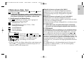 7
7
-
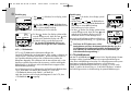 8
8
-
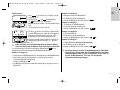 9
9
-
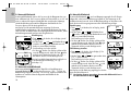 10
10
-
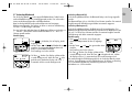 11
11
-
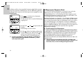 12
12
-
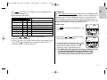 13
13
-
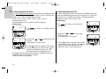 14
14
-
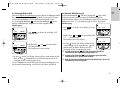 15
15
-
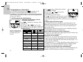 16
16
-
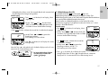 17
17
-
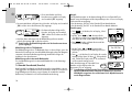 18
18
-
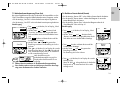 19
19
-
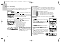 20
20
-
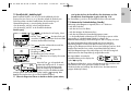 21
21
-
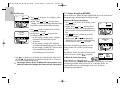 22
22
-
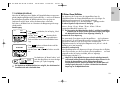 23
23
-
 24
24
-
 25
25
-
 26
26
-
 27
27
-
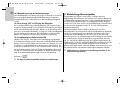 28
28
-
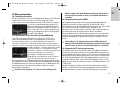 29
29
-
 30
30
-
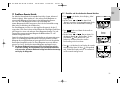 31
31
-
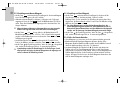 32
32
-
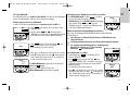 33
33
-
 34
34
-
 35
35
-
 36
36
-
 37
37
-
 38
38
-
 39
39
-
 40
40
-
 41
41
-
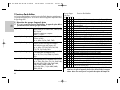 42
42
-
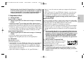 43
43
-
 44
44
-
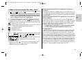 45
45
-
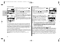 46
46
-
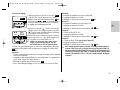 47
47
-
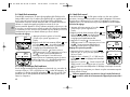 48
48
-
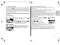 49
49
-
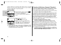 50
50
-
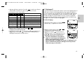 51
51
-
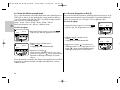 52
52
-
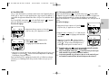 53
53
-
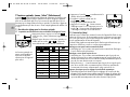 54
54
-
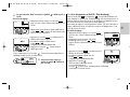 55
55
-
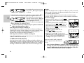 56
56
-
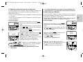 57
57
-
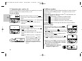 58
58
-
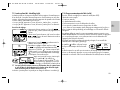 59
59
-
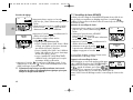 60
60
-
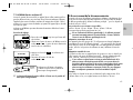 61
61
-
 62
62
-
 63
63
-
 64
64
-
 65
65
-
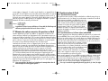 66
66
-
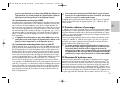 67
67
-
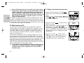 68
68
-
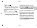 69
69
-
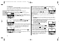 70
70
-
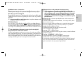 71
71
-
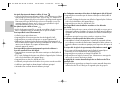 72
72
-
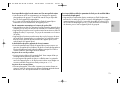 73
73
-
 74
74
-
 75
75
-
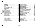 76
76
-
 77
77
-
 78
78
-
 79
79
-
 80
80
-
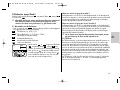 81
81
-
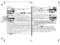 82
82
-
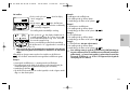 83
83
-
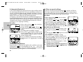 84
84
-
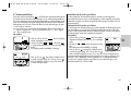 85
85
-
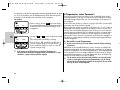 86
86
-
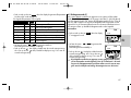 87
87
-
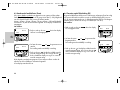 88
88
-
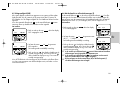 89
89
-
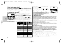 90
90
-
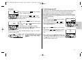 91
91
-
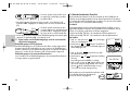 92
92
-
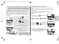 93
93
-
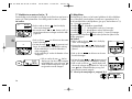 94
94
-
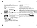 95
95
-
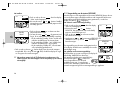 96
96
-
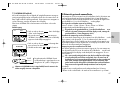 97
97
-
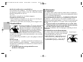 98
98
-
 99
99
-
 100
100
-
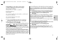 101
101
-
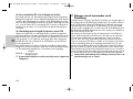 102
102
-
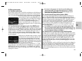 103
103
-
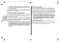 104
104
-
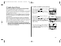 105
105
-
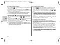 106
106
-
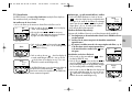 107
107
-
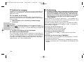 108
108
-
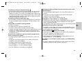 109
109
-
 110
110
-
 111
111
-
 112
112
-
 113
113
-
 114
114
-
 115
115
-
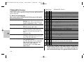 116
116
-
 117
117
-
 118
118
-
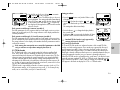 119
119
-
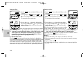 120
120
-
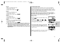 121
121
-
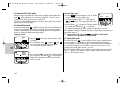 122
122
-
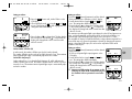 123
123
-
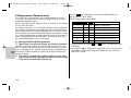 124
124
-
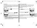 125
125
-
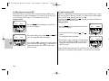 126
126
-
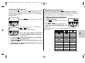 127
127
-
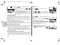 128
128
-
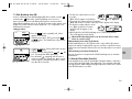 129
129
-
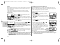 130
130
-
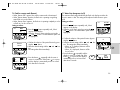 131
131
-
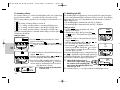 132
132
-
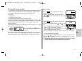 133
133
-
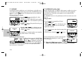 134
134
-
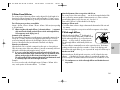 135
135
-
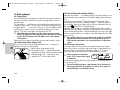 136
136
-
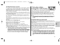 137
137
-
 138
138
-
 139
139
-
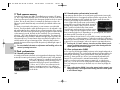 140
140
-
 141
141
-
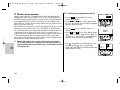 142
142
-
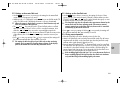 143
143
-
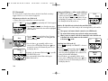 144
144
-
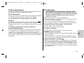 145
145
-
 146
146
-
 147
147
-
 148
148
-
 149
149
-
 150
150
-
 151
151
-
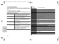 152
152
-
 153
153
-
 154
154
-
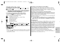 155
155
-
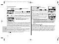 156
156
-
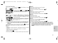 157
157
-
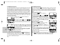 158
158
-
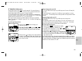 159
159
-
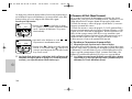 160
160
-
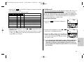 161
161
-
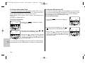 162
162
-
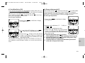 163
163
-
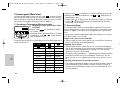 164
164
-
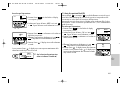 165
165
-
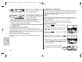 166
166
-
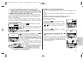 167
167
-
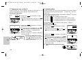 168
168
-
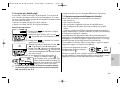 169
169
-
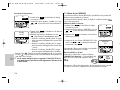 170
170
-
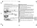 171
171
-
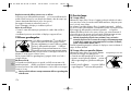 172
172
-
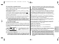 173
173
-
 174
174
-
 175
175
-
 176
176
-
 177
177
-
 178
178
-
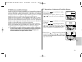 179
179
-
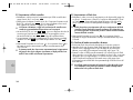 180
180
-
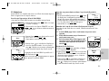 181
181
-
 182
182
-
 183
183
-
 184
184
-
 185
185
-
 186
186
-
 187
187
-
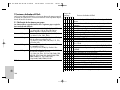 188
188
-
 189
189
-
 190
190
-
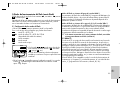 191
191
-
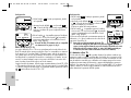 192
192
-
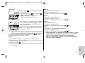 193
193
-
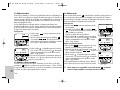 194
194
-
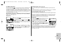 195
195
-
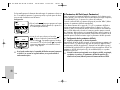 196
196
-
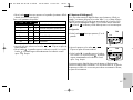 197
197
-
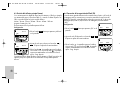 198
198
-
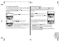 199
199
-
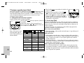 200
200
-
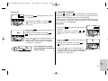 201
201
-
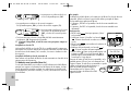 202
202
-
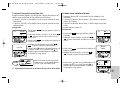 203
203
-
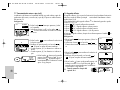 204
204
-
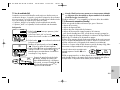 205
205
-
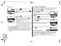 206
206
-
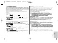 207
207
-
 208
208
-
 209
209
-
 210
210
-
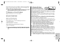 211
211
-
 212
212
-
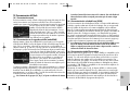 213
213
-
 214
214
-
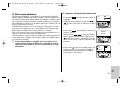 215
215
-
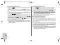 216
216
-
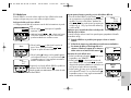 217
217
-
 218
218
-
 219
219
-
 220
220
-
 221
221
-
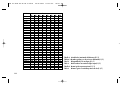 222
222
-
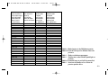 223
223
-
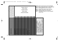 224
224
-
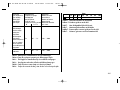 225
225
-
 226
226
-
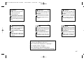 227
227
-
 228
228
-
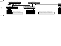 229
229
-
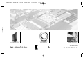 230
230


Metz mecablitz 58 AF-2 digital Nikon Manual de usuario
- Categoría
- Flashes de la cámara
- Tipo
- Manual de usuario
en otros idiomas
Artículos relacionados
-
Metz MECABLITZ 58 AF-1 Samsung El manual del propietario
-
-
-
-
-
-
Metz MECABLITZ 58 AF-2 digital El manual del propietario
-
Metz Mecablitz 64 AF-1 digital -Olympus-Panasonic-Leica El manual del propietario
-
Metz mecablitz 58 AF-1 digital Nikon El manual del propietario
-