Kichler Lighting 44033NI Manual de usuario
- Tipo
- Manual de usuario

Date Issued: 09/11/17 IS-44033-US
We’re here to help 866-558-5706
Hrs: M-F 9am to 5pm EST
CAUTION – RISK OF SHOCK –
Disconnect Power at the main circuit breaker panel or main
fusebox before starting and during the installation.
Before Installing:
All installations should comply with National and local electrical
codes. If you have any doubts concerning installation contact a
qualied licensed electrician.
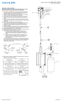
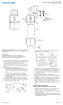
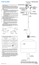
1) Find the appropriate threaded holes on mounting strap [1].
Assemble mounting screws [2] into threaded holes.
2) Attach mounting strap to outlet box [3]. (Screws not provided).
Mounting strap can be adjusted to suit position of xture.
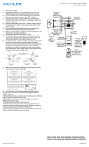
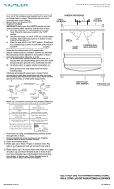
3) Grounding instructions: (See Illus. A or B).
A) On xtures where mounting strap is provided with a
hole and two raised dimples. Wrap ground wire from
outlet box around green ground screw, and thread into
hole.
B) On xtures where a cupped washer is provided. Attach
ground wire from outlet box under cupped washer and
green ground screw, and thread into mounting strap.
If xture is provided with ground wire. Connect xture ground
wire to outlet box ground wire with wire connector. (Not pro-
vided.) After following the above steps. Never connect ground
wire to black or white power supply wires.
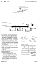
4) Make wire connections (connectors not provided). Reference
chart below for correct connections and wire accordingly.
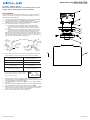
5) Push xture to ceiling, carefully passing mounting screws
through holes in canopy [4]. NOTE: Be certain wires do not get
pinched between canopy and ceiling.
6) Use knobs [5] and lockwashers [6] to secure canopy. Tighten
to secure.
7) Carefully raise glass [7] to the xture. Slip the smaller opening
over the bulb and t the glass against the socket [8].
8) While holding the glass in place, thread the thumbscrews [9]
into the holes in the side of the socket. Tighten to secure the
glass into place. (DO NOT OVER TIGHTEN).
9) Insert recommended bulb. (Not supplied)
We’re here to help 866-558-5706
Hrs: M-F 9am to 5pm EST
GREEN GROUND
SCREW
CUPPED
WASHER
OUTLET BOX
GROUND
FIXTURE
GROUND
DIMPLES
WIRE CONNECTOR
OUTLET BOX
GROUND
GREEN GROUND
SCREW
FIXTURE
GROUND
A
B
Connect Black or
Red Supply Wire to:
Connect
White Supply Wire to:
Black White
*Parallel cord (round & smooth) *Parallel cord (square & ridged)
Clear, Brown, Gold or Black
without tracer
Clear, Brown, Gold or Black
with tracer
Insulated wire (other than green)
with copper conductor
Insulated wire (other than green)
with silver conductor
*Note: When parallel wires (SPT I & SPT II)
are used. The neutral wire is square shaped
or ridged and the other wire will be round in
shape or smooth (see illus.)
Neutral Wire
7
8
9
5
6
4
1
2
3

Date Issued: 09/11/17 IS-44033-US
Estamos aquí para ayudarle 866-558-5706
Horario: Lunes-Viernes 9am a 5pm EST (hora ocial del este)
Antes de instalar:
Todas las instalaciones deben cumplir con las normas nacionales y
locales de códigos. Si tiene alguna duda sobre la instalación, pón
gase en contacto con un electricista calicado.
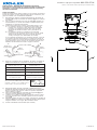
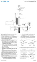
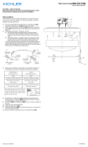
1) Encuentre los oricios roscados adecuados en la correa de
montaje [1]. Montar los tornillos de montaje [2] en los oricios
roscados.
2) Fije la correa de montaje a la caja de salida [3]. (Tornillos no
suministrados). La correa de montaje se puede ajustar para
adaptarse a la posición del aparato.
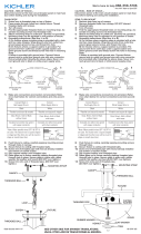
3) Instrucciones para poner a tierra: (Ver Ilustraciones A o B).
A) En artefactos donde se suministra la abrazadera de
montaje con un agujero y dos depresiones onduladas.
Envuelva el conductor de tierra de la caja de salida
alrededor del tornillo de tierra verde y atornille en el
agujero.
B) En artefactos donde se suministra una arandela
cóncava. Fije el conductor de tierra de la caja de salida
debajo de la arandela cóncava y el tornillo de tierra
verde y enrosque en la abrazadera de montaje.
Si se suministra el artefacto con conductor de tierra. Conecte
el conductor de tierra del artefacto al conductor de tierra de
la caja de salida con conector de tierra después de seguir los
pasos anteriores. Nunca conecte el conductor de tierra a los
alambres de alimentación eléctrica negros o blancos.
4) Haga las conexiones de los alambres. Re érase a la tabla de
abajo para realizar las conexiones correctas de los cables.
5) Empuje la jación al techo, pasando cuidadosamente los
tornillos de montaje a través de los oricios de la cubierta [4].
NOTA: Asegúrese de que los cables no queden atrapados
entre el techo y el techo.
6) Utilice las perillas [5] y las arandelas de seguridad [6] para
asegurar el dosel. Apriete para asegurar.
7) Levantar con cuidado el vidrio [7] al aparato. Deslice la aber-
tura más pequeña sobre el bulbo y ajuste el cristal contra el
zócalo [8].
8) Mientras sostiene el vaso en su lugar, enrosque los tornillos de
mariposa [9] en los oricios en el lado del zócalo. Apriete para
asegurar el vidrio en su lugar. (NO APRIETE MÁS).
9) Inserte la bombilla recomendada. (No incluido)
ARANDELA
CONCAVA
TIERRA DE LA
CAJA DE SALIDA
TORNILLO DE TIERRA,
VERDE
DEPRESIONES
TIERRA
ARTEFACTO
CONECTOR DE ALAMBRE
TIERRA DE LA
CAJA DE SALIDA
TORNILLO DE TIERRA,
VERDE
TIERRA
ARTEFACTO
A
B
Conectar el alambre de
suministro negro o rojo al
Conectar el alambre de
suministro blanco al
Negro Blanco
*Cordon paralelo (redondo y liso)
*Cordon paralelo (cuadrado y estriado)
Claro, marrón, amarillio o negro
sin hebra identificadora
Claro, marrón, amarillio o negro
con hebra identificadora
Alambre aislado (diferente del verde)
con conductor de cobre
Alambre aislado (diferente del
verde) con conductor de plata
*Nota: Cuando se utiliza alambre paralelo
(SPT I y SPT II). El alambre neutro es de forma
cuadrada o estriada y el otro alambre será de
forma redonda o lisa. (Vea la ilustracíón).
Hilo Neutral
PRECAUCIÓN – RIESGO DE DESCARGA ELÉCTRICA –
Desconecte la electricidad en el panel principal del interruptor
automático o caja principal de fusibles antes de comenzar y
durante la instalación.
7
8
9
5
6
4
1
2
3
-
 1
1
-
 2
2


Kichler Lighting 44033NI Manual de usuario
- Tipo
- Manual de usuario
en otros idiomas
- English: Kichler Lighting 44033NI User manual
Artículos relacionados
-
 Kichler Lighting 43898OZ Manual de usuario
-
 Kichler Lighting 43896OZ Manual de usuario
-
 Kichler Lighting 49857BKT Manual de usuario
-
 Kichler Lighting 49643OZ Manual de usuario
-
 Kichler Lighting 43895OZ Manual de usuario
-
 Kichler Lighting 3797CH Manual de usuario
-
 Kichler Lighting 43354CH Manual de usuario
-
 Kichler Lighting 44088CH Manual de usuario
-
 Kichler Lighting 42910PN Manual de usuario
-
 Kichler Lighting 44088CH Manual de usuario


