
L
AUX3 VIDEO IN
REAR VIDEO OUT
ZxZ AUDIO OUT AUX3 AUDIO IN REAR FRONT SUB OUT
CENTER
OUT
BUS AUDIO IN /
R
L
R
A
D
C
B
A
A
3
2
1
MIC IN
*
5
REVERSE IN
NAVI
/
CAMERA IN
AUX2 AUDIO IN
AUX1 VIDEO IN
AUX2 VIDEO IN
AUX1 AUDIO IN
BUS
CONTROL IN
AUX3 VIDEO
IN
*
7
ZxZ AUDIO
OUT
*
6
BUS AUDIO IN /
AUX3 AUDIO IN
*
7
REMOTE
IN
CENTER
OUT
REAR VIDEO OUT
REAR AUDIO OUT
FRONT AUDIO OUT
SUB OUT
Installation/Connections
Instalación/Conexiones
⫭塁濊䴾嵓徇㌉
To a car’s illumination signal
Be sure to connect the black ground (earth) lead to a metal
surface of the car fi rst.
To the +12 V power terminal which is
energized in the accessory position of the
ignition switch
Notes
• If there is no accessory position, connect to the +12 V
power (battery) terminal which is energized at all times.
Be sure to connect the black ground (earth) lead to a metal
surface of the car fi rst.
• When your car has a built-in FM/AM antenna (aerial) in the
rear/side glass, see “Notes on the control and power supply
leads.”
To the +12 V power terminal which is
energized at all times
Be sure to connect the black ground (earth) lead to a metal
surface of the car fi rst.
To the parking brake switch cord
To auxiliary equipment such as a portable
media player, game, etc. (not supplied)
Tip
You can use the supplied RCA pin cord , or an optional
one.
To the back camera or navigation device (not
supplied)
To the +12 V power terminal of the car’s back
lamp lead (only when connecting the back
camera)
To the microphone (not supplied)
Notes on the control and power supply leads
• The power antenna (aerial) control lead (blue) supplies +12 V
DC when you turn on the tuner.
• When your car has built-in FM/AM antenna (aerial) in the
rear/side glass, connect the power antenna (aerial) control lead
(blue) or the accessory power supply lead (red) to the power
terminal of the existing antenna (aerial) booster. For details,
consult your dealer.
• A power antenna (aerial) without a relay box cannot be used
with this unit.
Memory hold connection
When the yellow power supply lead is connected, power will
always be supplied to the memory circuit even when the ignition
switch is turned off.
Notes on speaker connection
• Before connecting the speakers, turn the unit off.
• Use speakers with an impedance of 4 to 8 ohms, and with
adequate power handling capacities to avoid its damage.
• Do not connect the speaker terminals to the car chassis, or
connect the terminals of the right speakers with those of the left
speaker.
• Do not connect the ground (earth) lead of this unit to the
negative (–) terminal of the speaker.
• Do not attempt to connect the speakers in parallel.
• Connect only passive speakers. Connecting active speakers
(with built-in amplifi ers) to the speaker terminals may damage
the unit.
• To avoid a malfunction, do not use the built-in speaker leads
installed in your car if the unit shares a common negative (–)
lead for the right and left speakers.
• Do not connect the unit’s speaker leads to each other.
Notes on connection
• If speaker and amplifi er are not connected correctly, “FAILURE”
appears in the display. In this case, make sure the speaker and
amplifi er are connected correctly.
• If you are to use the monitor for the rear seats, connect the
parking brake switch cord to the ground (earth).
REAR AUDIO
OUT
SUB OUT
CENTER
OUT
FRONT AUDIO
OUT
REAR VIDEO
/
ZxZ AUDIO OUT
BUS AUDIO IN
BUS CONTROL IN
NAVI
/
CAMERA
IN
AUX AUDIO
IN
AUX AUDIO
IN
AUX VIDEO
IN
AUX VIDEO
IN
AUX AUDIO
IN
A
B
Equipment used in illustrations (not supplied)
Equipo utilizado en las ilustraciones (no suministrado)
㌶♺ᶑ䗨塁仒濃曂斨彥濄
from car antenna (aerial)
desde la antena del automóvil
Ừ兎㯡帮⢍䴾
Rear speaker
Altavoz posterior
⻰㌾俖◌
Front speaker
Altavoz frontal
↱㌾俖◌
Power amplifi er
Amplifi cador de potencia
∃䋫㒢⢋◌
Cautions
• This unit is designed for negative ground (earth) 12 V
DC operation only.
• Do not disassemble or modify the unit.
• Do not install in locations which interfere with airbag
operation.
• Do not get the leads under a screw, or caught in moving
parts (e.g. seat railing).
• Before making connections, turn the car ignition off to
avoid short circuits.
• Connect the yellow and red power supply leads only
after all other leads have been connected.
• Run all ground (earth) leads to a common
ground (earth) point.
• Be sure to in su late any loose un con nect ed leads with
electrical tape for safety.
• Do not press on the LCD when installing the unit.
• Do not install the unit with the monitor angle changed.
Notes on the power supply lead (yellow)
• When connecting this unit in combination with other
stereo components, the connected car circuit’s rating
must be higher than the sum of each component’s fuse.
• When no car circuits are rated high enough, connect
the unit directly to the battery.
Parts list
The numbers in the list are keyed to those in the
instructions.
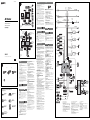
Connection example
Notes (-
A
)
• Be sure to connect the ground (earth) lead before connecting
the amplifi er.
• The alarm will only sound if the built-in amplifi er is used.
Note (-
B
)
You cannot use the optional devices simultaneously, even if they
are connected to the all terminals. If you connect an optional
device to BUS CONTROL IN, AUX3 IN is not available.
Tip (-
B)
For connecting two or more CD changers, the source selector
XA-C40 (not supplied) is necessary.
Connection diagram
To a metal surface of the car
First connect the black ground (earth) lead, then connect the
yellow and red power supply leads.
To the power antenna (aerial) control lead or
power supply lead of antenna (aerial) booster
Notes
• It is not necessary to connect this lead if there is no power
antenna (aerial) or antenna (aerial) booster, or with a
manually-operated telescopic antenna (aerial).
• When your car has a built-in FM/AM antenna (aerial) in
the rear/side glass, see “Notes on the control and power
supply leads.”
To AMP REMOTE IN of an optional power
amplifi er
This connection is only for amplifi ers. Connecting any other
system may damage the unit.
To the interface cable of a car telephone
× 8
CD changer
Cambiador de CD
DE!㌿䠃㧃
Source selector*
Selector de fuente*
杗㷴応㐫◌*
XA-C40
* not supplied
no suministrado
! 曂斨彥
AMP REM
Max. supply current 0.3 A
Corriente máx. de alimentación de 0,3 A
㙤⢋晟㲥!1/4!B
Fuse (10 A)
Fusible (10 A)
ὁ明䳖!)21!B*
Blue/white striped
Con rayas azules y blancas
唱濊䗡㠁䱯
Red
Rojo
䱩凖
Yellow
Amarillo
渧凖
White
Blanco
䗡凖
Green
Verde
䴄凖
Purple
Morado
䲏凖
White/black striped
Con rayas blancas y negras
䗡濊渵㠁䱯
Gray/black striped
Con rayas grises y negras
㿔濊渵㠁䱯
Green/black striped
Con rayas verdes y negras
䴄濊渵㠁䱯
Gray
Gris
㿔凖
Left
Izquierdo
ⵊ
Right
Derecho
⍗
Left
Izquierdo
ⵊ
Right
Derecho
⍗
ANT REM
Black
Negro
渵凖
Blue
Azul
唱凖
Max. supply current 0.1 A
Corriente máx. de alimentación de 0,1 A
㙤⢋晟㲥 1/2!B
Purple/black striped
Con rayas moradas y negras
䲏濊渵㠁䱯
Source selector
(not supplied)
Selector de fuente
(no suministrado)
杗㷴応㐫◌
)曂斨彥*
XA-C40
Supplied with the CD changer
Suministrado con el cambiador de CD
斨㔠!DE!㌿䠃㧃
Rotary commander RM-X4S
Mando rotatorio RM-X4S
㔯庭㌋↚◌!SN.Y5T
*
4
3-216-786-61 (1)
AV Center
XAV-W1
©
2007 Sony Corporation Printed in Taiwan
* not supplied
no suministrado
! 曂斨彥
Monitor (not supplied)
Monitor (no suministrado)
䙇壺◌!)曂斨彥*
*
1
RCA pin cord (not supplied)
*
2
Insert with the cord upwards.
*
3
Supplied with XA-C40
*
4
For details on connecting to the parking brake switch
cord, see “Connecting the parking brake cord ()” on
the reverse side.
*
5
For details on connecting to the MIC input cord, see
“Connecting a microphone ()” on the reverse side.
*
6
The sound is output from this terminal only when ZONE
x ZONE is activated. This terminal outputs a fi xed level
regardless of the volume control of the unit.
*
7
If you connect an optional device to BUS CONTROL IN,
AUX3 IN is not available.
*
8
Do not remove the protective device.
*
2
Light green
Verde claro
㵅䴄凖
*
1
Cable con terminales RCA (no suministrado)
*
2
Insertar con el cable hacia arriba.
*
3
Suministrado con el XA-C40
*
4
Para obtener detalles acerca de cómo conectar el cable
de conmutación del freno de estacionamiento, consulte
“Conexión del cable del freno de estacionamiento ()”
en el dorso.
*
5
Para obtener detalles acerca de cómo conectar el cable
de entrada MIC, consulte “Conexión de un micrófono
()” en el dorso.
*
6
El sonido se emitirá a través de este terminal sólo
cuando esté activado ZONE x ZONE. Este terminal
emite a un nivel fi jo independientemente del control de
volumen de la unidad.
*
7
Si se conecta un dispositivo opcional a BUS CONTROL
IN, AUX3 IN no estará disponible.
*
8
No retire el dispositivo de protección.
*
1
!SDB!慁⛯㌶枑晟䴾濃曂斨彥濄
*
2
!晟䴾⍵ᵮ㌶Ɂ
*
3
!斨㔠!YB.D51
*
4
!㙭敀徇㌉兗῀帮↚∹晟䴾䗨姗䲔娎㕲濇娯⌧壯倰曆䗨ĥ徇
㌉῀帮↚∹晟䴾濃濄ĦɁ
*
5
!㙭敀徇㌉兗NJD府⭲䴾䗨姗䲔娎㕲濇娯⌧壯倰曆䗨ĥ徇
㌉渉₯栌濃濄ĦɁ
*
6
!䓚Ⓝ∹
to dashboard/center console
al tablero o consola central
兗埌㛣濊ᶑ⢒㌋↚䬕
Bracket
Soporte
ㆼ㜚
Bracket
Soporte
ㆼ㜚
Existing parts supplied with your car
Piezas existentes suministradas con su automóvil
昌㯡帮斨彥䗨恌Ṛ
max. size
5 × 8 mm
(
7
/32 ×
11
/32 in)
Tamaño máx.
5 × 8 mm
㙤⢋⮞⭜
69!nn
max. size
5 × 8 mm
(
7
/32 ×
11
/32 in)
Tamaño máx.
5 × 8 mm
㙤⢋⮞⭜
69!nn
Foot brake type
Tipo de freno de pedal
僗↚∹⛯
Parking brake switch cord
Cable de conmutación del
freno de estacionamiento
῀帮↚∹擯敀晟䴾
Hand brake type
Tipo de freno manual
ㆯ↚∹⛯
Parking brake switch cord
Cable de conmutación del
freno de estacionamiento
῀帮↚∹擯敀晟䴾
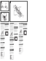
Precautions
• Choose the installation location carefully so that the
unit will not interfere with normal driving operations.
• Avoid installing the unit in areas subject to dust, dirt,
excessive vibration, or high temperatures, such as in
direct sunlight or near heater ducts.
• Use only the supplied mounting hardware for a safe
and secure installation.
• To open/close the front panel smoothly, insert/eject
a disc easily, and especially to drive safely, a certain
distance between the front panel and the shift lever is
necessary. The necessary distance differs, depending on
the shift lever position of your car. Before installing the
unit, choose the installation location carefully so that
you can drive safely.
87.8 mm
(3
1
/2 in)
Shift lever
Mounting angle adjustment
Adjust the mounting angle to less than 45°.
Connecting the parking brake
cord
Be sure to connect the parking cord (light green) of
to the parking brake switch cord. The mounting position
of the parking brake switch cord depends on your car.
Consult your car dealer or your nearest Sony dealer for
further details.
Connecting a microphone
You can connect a microphone (not supplied) to enjoy
karaoke.
Notes
• Whether in use or not, route the MIC input cord such that it
does not interfere with driving. Secure with a cord clamp, etc.,
if the cords are installed around your feet.
• The karaoke function is unavailable while driving.
Mounting the unit in a Japanese
car
You may not be able to install this unit in some makes of
Japanese cars. In such a case, consult your Sony dealer.
When mounting this unit to the preinstalled brackets of
your car, use the supplied screws in the appropriate
screw holes, according to your car: T for TOYOTA, M
for MITSUBISHI and N for NISSAN.
T
N
T
M
N
M
T
N
M
N
N
T
T
Notes
• To prevent malfunction, install only with the supplied screws
.
• Do not apply excessive force to the buttons of the unit.
• Do not press on the LCD.
• Before mounting, make sure there is nothing on the top of the
unit.
Warning if your car’s ignition
has no ACC position
Be sure to set the Auto Off function. For details, see the
supplied Operating Instructions.
The unit will shut off completely and automatically in
the set time after the unit is turned off, which prevents
battery drain.
If you do not set the Auto Off function, press and hold
until the display disappears each time you turn
the ignition off.
Reset button
When the installation and connections are completed,
be sure to press the reset button with a ball-point pen, etc.
Precauciones
• Elija cuidadosamente el lugar de montaje de forma que
la unidad no interfi era con las funciones normales de
conducción.
• Evite instalar la unidad donde pueda quedar sometida
a polvo, suciedad, vibraciones excesivas o altas
temperaturas como, por ejemplo, a la luz solar directa o
cerca de conductos de calefacción.
• Para realizar una instalación segura y fi rme, utilice
solamente elementos de instalación suministrados.
• Para abrir/cerrar el panel frontal con suavidad, insertar/
extraer discos fácilmente y sobre todo para conducir
con seguridad, es necesario mantener cierta distancia
entre el panel frontal y la palanca de cambios. La
distancia necesaria varía en función de la posición de la
palanca de cambios de su automóvil. Antes de instalar
la unidad, elija cuidadosamente el lugar de instalación
para que pueda conducir con seguridad.
87,8 mm
Palanca de
cambios
Ajuste del ángulo de montaje
Ajuste el ángulo de montaje a menos de 45°.
Conexión del cable del freno de
estacionamiento
Asegúrese de conectar el cable del freno (verde claro) de
al cable de conmutación del freno de estacionamiento.
La posición de montaje del cable de conmutación
del freno de estacionamiento depende del automóvil.
Consulte al distribuidor del automóvil o al distribuidor
Sony más cercano para obtener más detalles.
Conexión de un micrófono
Es posible conectar un micrófono (no suministrado) y
disfrutar de la función de karaoke.
Notas
• Se esté utilizando o no, coloque el cable de entrada MIC
de modo que no interfi era en el manejo del automóvil. Si
instala los cables cerca de la zona de los pies, fíjelos con una
abrazadera, etc.
• La función de karaoke no está disponible mientras maneja el
automóvil.
Montaje de la unidad en un
automóvil japonés
Es posible que no pueda instalar esta unidad en algunos
automóviles japoneses. En tal caso, consulte a su
distribuidor Sony.
Cuando monte la unidad en los soportes preinstalados de
su automóvil, utilice los tornillos suministrados en los
orifi cios para tornillos correspondientes en función de su
automóvil: La T indica TOYOTA; la M, MITSUBISHI; y
la N, NISSAN.
T
N
T
M
N
M
T
N
M
N
N
T
T
Notas
• Para evitar que se produzcan fallas de funcionamiento, realice
la instalación solamente con los tornillos suministrados .
• No ejerza excesiva fuerza sobre los botones de la unidad.
• No presione la pantalla LCD.
• Asegúrese de que no hay ningún objeto encima de la unidad
antes de montarla.
Advertencia: si el encendido del
automóvil no dispone de una
posición ACC
Asegúrese de ajustar la función de desconexión
automática. Para obtener más información, consulte el
manual de instrucciones suministrado.
La unidad se apagará completa y automáticamente en
el tiempo establecido después de que se desconecte la
unidad, lo que evita que se desgaste la batería.
Si no ha ajustado la función de desconexión automática,
mantenga presionado cada vez que apague
el interruptor de encendido, hasta que la pantalla
desaparezca.
Botón de reinicio
Una vez fi nalizadas la instalación y las conexiones,
asegúrese de presionar el botón de reinicio con un
bolígrafo, etc.
ợ䒌↱㱌びᷯ杩
•!Ḹ䲔応⌺⫭塁ằ仒濇ṉợ㚐㧃ᵱⷖ㑢㫇䗨椹椿㐱
ỀɁ
•!忣₱⭫㚐㧃⫭塁⚌⌻㿔⟙ɀ㯅䇍⏰⺛䀬㊓∹⻕杣䗨
⊤❃濇ㅺ⫭塁⚌樼㸏喹濇⣦䙘⭱旡₭ᵯㅺ䄕㮇䬅德
斨張Ɂ
•!䀞ᷪ⫭塁⫭⏰⍓曄濇⍎偡ợ䒌斨彥䗨⫭塁㤯ṚɁ
•!剉壥偡⢄杪ㆷ擯0敀擭↱曆㛣ɀ幹㕷㌶0彤⅞₭
䠃濇䇝↉㖓䀞ᷪ⫭椹帮濇↱曆㛣八㋶㧸㟣ᶯ擷晤
ὁ㉥ᵤ⫾䗨嵁晆Ɂ㫈嵁晆⼩杬壺「帮㋶㧸㟣䗨ằ
仒佰⫾Ɂ⫭塁㚐㧃↱濇娯媝ゲ応㐫⫭塁ằ仒濇ṉἣ
偡⫭椹帮Ɂ
98/9!nn
㋶㧸㟣
⫭塁夶⸊娣㓘
娯⚌!56ṉ娣㓘⫭塁夶⸊Ɂ
徇㌉῀帮↚∹晟䴾!
⼩杬⭫!!䗨῀帮晟䴾濃㵅䴄凖濄八῀帮↚∹擯敀
晟䴾徇㌉Ɂ῀帮↚∹擯敀晟䴾䗨⫭塁ằ仒⌺㯞㔠「䗨
㯡帮Ɂ㙘姗䲔尫奮濇娯俓䳅「䗨㯡帮䳷戛⒪ㅺ斨張䗨!
Tpoz!䳷戛⒪Ɂ
徇㌉渉₯栌!
「⍓ṉ徇㌉渉₯栌濃曂斨彥濄佰㫅⒕⋅㈭!PLɁ
妟
•!䂅娺ợ䒌八⎊濇恡ㄭ⭫NJD府⭲䴾㋶ⵧ⚌ᵱ㙧⻕杣↔椹帮䗨ằ
仒Ɂ⣦㜀⭲䴾晤⫭塁⚌僗䗨⏌♱濇娯䒌⭲䴾⢢䪭徖垰♞⫾Ɂ
•!椹帮㖦䂅㰹ợ䒌⋅㈭!PL!∃偡Ɂ
⭫㚐㧃⫭塁㔠㕉㚐䒆㯡帮ᵮ!
㙭᷿㕉㚐䒆㯡帮ᵱ偡⫭塁㚐㧃Ɂ⚌彽䦒〩⻆ᵯ濇娯⍵!
Tpoz!䳷戛⒪婒姆Ɂ
䓚「⭫㚐㧃⫭塁↔帮䗨杴妑ㆼ㜚㖦濇娯ἁ㐾「䗨㯡
帮⹄䆰濇⚌忍䓚䗨圞䳖⪸ợ䒌斨彥䗨圞䳖!濕U!ṇ
埌!UPZPUB濇N!ṇ埌!NJUTVCJTIJ濇O!ṇ埌!OJTTBOɁ
T
N
T
M
N
M
T
N
M
N
N
T
T
妟
•!䀞斖㫆䗠䒃㒩昀濇⫭塁㖦⍎偡ợ䒌斨彥䗨圞䳖!Ɂ
•!娯≣徲⸊⢋⇿㉭⠷㚐㧃㉭慹Ɂ
•!娯≣㉭⠷!MDEɁ
•!⫭塁ᶯ↱濇娯䠞⫾㚐㧃ᵮ㔝䂅ṟẹ䇍␥Ɂ
⣦㜀「䗨㯡帮湂㿏擯敀㯶㙭!
BDD!ằ仒㖦䗨嫊⎮
∽⼩妑⫾!Bvup!Pgg!∃偡Ɂ剉晤ᷪ奇姗䲔尫奮濇娯⌧
攕昌斨䗨ợ䒌娎㕲㙜Ɂ
敀擭㚐㧃ṉ⻰㚐㧃㙧⚌妑⫾㖦擷兎∹曆敀㧃濇ṉ
忣₱晟䑚佻晟Ɂ
剉「㚎妑⫾!Bvup!Pgg!∃偡濇娯㉭ẳ!!䙘↔「
㬳㪅敀擭湂㿏擯敀䙯↔染䢞㳬⢕䆖㫆Ɂ
愱妑㉭慹
⫰ㅴ⫭塁八徇㌉㫉槃㖦濇娯∽⼩䒌⌃⪴䪪柂䗨䇍␥㉭
ᵯ愱妑㉭慹Ɂ
-
 1
1
-
 2
2

