dosatron PJDI122V Instrucciones de operación
- Tipo
- Instrucciones de operación

PDI702
20M046
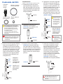
Instructions
(Parts included in kit noted in blue)
Unscrew injection stem assembly nut
(PDI702) and set aside. Pull down
on stem to detach from body of unit.
Remove the hose clamp (20M046).
1.
PDI702
20M046
Unscrew check valve nut (PDI747)
and pull out check valve assembly
(PJDI118V). It will come out in one
piece. Discard.
2.
PJDI118V
PDI747
Unscrew locking nut (PDI746),
remove “C” clamp (PDI751) by
slightly spreading the opening
and gently sliding it down over the
threads. Unscrew adjusting sleeve
(PPDI037). Holding the sleeve
(PDI741), push up on the threaded
part of the injection stem (PDI743)
and slide it out of the sleeve from
the top. Replace both sleeve and
injection stem o-rings (JDI100 and
JDI122).
3.
JDI123
JDI122
JDI100
PDI743
PDI741
PDI702
PPDI037
PDI751
PDI746
To remove o-ring
easily without tools,
squeeze it on either
side to raise the
seal, then slide it
over the groove
Remove and
replace plunger
seal (JDI123),
using same
method as above.
4.
Using tools could
damage the
plunger and aect
the injection rate
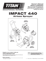
Slide the injection stem (PDI743)
down into the sleeve (PDI741),
making sure the small key located on
the bottom inside of the sleeve is
properly aligned with the longest
groove on the white stem. Holding the
black sleeve, pull down on the white
stem as far as it will go. Screw adjust-
ing sleeve (PPDI037) back onto the
sleeve (PDI741).
5.
JD123
JDI122
JDI100
PDI743
PDI741
PDI702
PPDI037
PDI751
PDI746
Reinstall “C”
clamp by sliding
it gently over the
thread at the
bottom of the
white stem.
Rotate clamp
until it clicks into
place.
Screw locking
nut (PDI746)
back on.
Insert new check valve (PJDI118V)
at the bottom of the stem, making sure
that the 4 white keys on the check
valve seat next to the 4 black keys on
the bottom of the stem. Screw check
valve nut (PDI747) back on.
6.
Push injection stem
assembly in
position at the
bottom of the
blue body, making
sure desired scale
is facing front of
injector. Screw
injection stem nut
(PDI702). Insert
hose onto the bottom
7.
To ensure hose is air-tight, you
may choose to carefully cut the top
of hose before reinserting.
Kit Contents:
PJDI118V: Check
valve assembly
JDI100: Sleeve
o-ring
JDI123: Plunger
seal
We recommend cleaning all parts with warm
soapy water and a toothbrush before
installing the new parts.
Water normally lubricates the parts, but you
may use silicone on the o-ring to facilitate
insertion.
Check valve may be taken apart and
cleaned in between maintenance to remove
particles.
JDI122: Injection
stem o-ring
STOP
CAUTION: Parts may contain
concentrated chemicals. The use of Prop-
er Protective Equipment is recommended
when performing maintenance.
PJDI118V
PDI747
of the check valve barb (PJDI118V).
Attach the clamp (20M046).
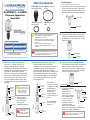
Part # PJDI122V
D14TMZ10 - 14 GPM
Viscous Injection
Seal Kit
(1) JDI123 Plunger seal
(1) JDI122 Injection stem o-ring
(1) JDI100 Sleeve o-ring
(1) PJDI118V Check valve assembly
This kit contains:
Vea el reverso para
instrucciones en Español.

Instrucciones
(Partes en color azul están incluídas en el kit)
Desatornille la tuerca del cono de
inyección (PDI702) y colóquela a un
lado. Jale hacia abajo el cono de inye-
cción hasta separarlo del cuerpo de la
unidad. Remueva la abrazadera de la
manguera (20M046).
1.
Desatornille la tuerca (PDI747) y
remueva la válvula cheque
(PJDI118V). Esta saldrá en una
sola pieza. Deséchela.
2.
Desatornille la tuerca de seguridad
(PDI746), remueva la arandela en
forma de “C” (PDI751). Desatornille
la manga de ajuste (PPDI037). Su-
jetando la manga (PDI741), empuje
hacia arriba la parte del cono de
inyección con rosquilla (PDI743) y
sáquela completamente de la man-
ga. Reemplace ambos o-rings, el de
la manga y el del cono de inyección
(JDI100 y JDI122).
3.
JDI123
JDI122
JDI100
PDI743
PDI741
PDI702
PPDI037
PDI751
PDI746
Para remover facil-
mente el o-ring sin
uso de herramien-
tas, apriete ambos
lados del o-ring y
este levantara una
parte para poder
ser extraído.
Remueva y reem-
place el sello del
embolo (JDI123),
usando el mismo
método descrito
anteriormente.
4.
El uso de herra-
mientas podría
dañar el embolo
afectando el índice
de inyección.
Inserte el cono de inyección (PDI743)
dentro de la manga (PDI741), ase-
gurándose que las marcas ubicadas
en la parte inferior dentro de la manga
coincidan con las ranuras en el cono
(barra blanca). Sujetando la manga
negra, jale hacia abajo el cono (barra
blanca) tanto como pueda. Atornille
la manga de ajuste (PPDI037) a la
manga (PDI741).
5.
JDI123
JDI122
JDI100
PDI743
PDI741
PDI702
PPDI037
PDI751
PDI746
Reinstale la
arandela en
forma de “C”,
rotándola hasta
que haga clic.
Atornille en su
lugar la tuerca
de seguridad
(PDI746).
Inserte la nueva válvula cheque
(PJDI118V) en la parte inferior del
cono (barra blanca), asegurándose
que las 4 marcas en la válvula cheque
queden alineadas con las 4 marcas en
la parte inferior del cono. Atornille de
nuevo la tuerca de la válvula cheque
(PDI747).
Para asegurarse que haya una succión
adecuada, usted puede cortar con
cuidado el nal de la manguera en
línea recta.
Inserte todo el montaje de inyección
en la unidad, empujándolo comple-
tamente hasta que esté en posición.
Girando el montaje de inyección,
usted puede asegurarse que la escala
deseada (Porcentajes o proporciones)
se encuentra en la parte frontal del
inyector. Atornille la tuerca (PDI702).
Inserte la manguera en la parte inferior
al nal de la válvula cheque
(PJDI118V) y vuelva a colocar la
abrazadera de la manguera (20M046).
7.
6.
Contenido del Kit:
PJDI118V:
Válvula
cheque
JDI100: O-ring del
cono de inyección
JDI122: O-ring
parte superior
JDI123: Sello del
embolo
Recomendamos limpiar todas las partes
con agua tibia jabonosa y un cepillo de dien-
tes, antes de instalar las partes nuevas.
El agua normalmente lubrica las partes,
pero usted puede usar silicón en el o-ring
para facilitar la inserción.
La válvula cheque se puede desarmar y
limpiar entre mantenimientos para remover
las partículas.
STOP PRECAUCIÓN: Las partes pueden
contener químicos concentrados. El uso
de Equipo de Protección Adecuado es
recomendado cuando se efectúa el
mantenimiento.
PDI702
20M046
PJDI118V
PDI747
PJDI118V
PDI747
PDI702
20M046
-
 1
1
-
 2
2


dosatron PJDI122V Instrucciones de operación
- Tipo
- Instrucciones de operación
en otros idiomas
Artículos relacionados
Otros documentos
-
Simplicity 01906-0 Manual de usuario
-
Titan Impact 440 Service Manual Manual de usuario
-
-
-
-
-
 Dino-Power Titan 440i El manual del propietario
-
WAGNER EP2205 El manual del propietario
-
