
2
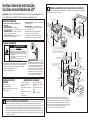
PREPARE THE OPENING (FOR INDOOR USE ONLY)
NOTE: Drop-In Ranges are designed to hang from the countertop only. Do not install on a platform or
sup port rails.
BEFORE YOU BEGIN
Read these instructions completely and
carefully.
•
,03257$17³ Save these
instructions for local inspector’s use.
•
,03257$17³ Observe all
governing codes and ordinances.
• Note to Installer – Be sure to leave these
instructions with consumer.
• Note to consumer – Keep these
instructions for future reference.
• Skill level – Installation of this appliance
requires a qualified installer or electrician.
• Proper installation is the responsibility of the
installer.
• Product failure due to improper installation is
not covered under warranty.
FOR YOUR SAFETY:
If you did not receive an anti-tip bracket with your purchase,
call 1.800.626.8774 to receive one at no cost. (In Canada,
call 1.800.561.3344.) For installation instructions of the bracket,
visit: www.GEAppliances.com. (In Canada, www.GEAppliances.ca.)
Installation Instructions
30” Electric Drop-In Ranges
MATERIALS YOU MAY NEED TOOLS YOU WILL NEED
Junction Box
Wire Nuts
Strain Relief Clamp for 1/2” Conduit
1
REMOVE PACKAGING MATERIALS: Failure to remove packaging materials could
result in damage to the appliance. Remove all packing parts from oven, racks, and heating
elements. Remove protective film and labels on the outer door and control panel. Also remove
plastic on trims and panel and all tape around the oven. Open oven door and remove literature
pack and oven racks. Remove the bottom trim from the side of the oven. It will be installed at the
end of the installation process. The trim is wrapped separately in a plastic bag which will also
contain the 4 screws to secure the bottom trim and the 2 shoulder screws used to secure the
product to the cabinet.
1/8” Drill Bit and Electric
Drill
Phillips Screwdriver
Level
Flathead Screwdriver
Tape Measure
1/4” Nut Driver
Straight edge or Square
Hammer
Hand or Saber Saw
Pencil
Safety Glasses
• A child or adult can tip the range and be killed.
• Install the anti-tip bracket to the wall or floor.
• Engage the range to the anti-tip bracket by sliding the
range back such that the foot is engaged.
• Re-engage the anti-tip bracket if the range is moved.
• Failure to do so can result in death or serious burns
to children or adults.
Tip-Over Hazard
WARNING
Questions? Call 1.800.GE.CARES (1.800.432.2737) or visit www.GEAppliances.com
In Canada, call 1.800.
561.3344
or visit www.GEAppliances.ca
WARNING
³
Before beginning
the installation, switch power off at service
panel and lock the service disconnecting
means to prevent power from being
switched on accidentally. When the service
disconnecting means cannot be locked,
securely fasten a prominent warning device,
such as a tag,
to the service panel.
Oven
Anti-Tip Bracket
Countertop or
Wood Block
Rear
Wall
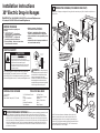
Allow 30” minimum clearance between surface units and
bottom of unprotected wood or metal cabinet. Allow a 24”
minimum when bottom of wood or metal is protected by no
less than 1/4” thick flame retardant millboard covered with not
less than No 28 MSG sheet metal (.015”), .015” thick stainless
steel, .024” aluminum or .020” copper.

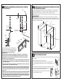
2
PREPARE THE OPENING (FOR INDOOR USE ONLY) (Continued)
3
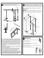
WHEN INSTALLING RANGE IN COUNTERTOP CUT OUT TO WALL
If the counter opening extends to the walls, it will require maintop filler kit WB07T1068X or backguard
kit JXS32XX to close the gap. Refer to the filler or back guard kit instructions for installation details.
NOTE: If the countertop is greater than 25” it will show a gap between the back-guard and wall or
between filler kit and the wall.
WARNING: An additional anti-tip bracket support must be mounted to the rear wall of the
cutout. The anti-tip bracket support is typically a 2x4 piece of lumber screwed directly into the wall
studs. The anti-tip bracket support must be able to withstand 200 lbs of force at the engagement
point.
4
REMOVE OVEN DOOR
Door removal is not a requirement for installation of the product but is an added
convenience. To remove the door:
1. Open the oven door as far as it will go.
2. Push both hinge locks toward the door frame to the unlocked position. This
may require a flat blade screwdriver.
3. Place hands on both sides of the door, and close the door to the removal position. This is half way
between the broil stop and fully closed.
4. Lift the door up and out until the hinge arms clear the slots.
Wall
1/4” min. flat
23-3/16”
9/16” min.
flat
9/16” min.
flat
29-15/16”– 30-1/16”
smooth cut
25”
typically
The Standard Installation of this Drop-In Range is to hang by the countertop on the side metal flang es
under glass cooktop. This Range must not be installed on a base or sub structure (2”x 4” support).
If the construction of your cabinet cannot provide a 1/4” flat area at the back of the countertop
opening, consider changing the countertop to accommodate this dimension. If the area is not flat,
excess tension may be applied to the glass cooktop, causing breakage and voiding the warranty.
• Countertop thickness 1-1/4” min. is required to support the product. Braces must be installed
between the underside of the countertop and the cabinet if required to obtain 1-1/4” minimum
thickness (each side).
• Make sure the wall coverings, counters and cabinets around the oven can withstand the heat (up
to 200° F (93.3° C) generated by the oven.
• This appliance has been approved for 0” spacing to adjacent surfaces above the cooktop.
However, a 6” minimum spacing to surfaces less than 15” above the cooktop and adjacent
cabinet is recommended to reduce exposure to steam, grease splatter and heat.
• Locate the wiring junction box at the rear of the cutout. The dimension from the top of the wiring
junction box to the countertop must be a minimum of 28-1/2”. The box must not extend more
than 3” off the plane of the wall. The junction box must be located where it will allow considerable
slack in the range conduit, so that the range can be pulled out for service if necessary.
1/4”
R
Flat
area
Countertop
Range support
29-15/16” Min.
30-1/16” Max.
10-3/8” from
countertop to
anti-tip support
25”
9/16”
9/16”
Must be Flat
Must be Flat
Anti-Tip Support
Wall
Hinge Lock
(Unlocked
Position)
Hinge
Slot
Hinge Arm
Hinge
Clears Slot

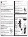
5
ELECTRICAL REQUIREMENTS
WARNING Electric Shock Hazard
• This appliance must be properly grounded.
• Do not use an extension cord.
•
Before installing range, switch power off at the service panel and lock the service disconnecting means
to prevent power from being switched on accidentally. When the disconnection means cannot be locked,
securely fasten a prominent warning device, such as a tag, to the service panel.
Failure to follow these instructions may result in serious injury or death.
WARNING Fire Hazard
Improper connection of aluminum house wiring to copper leads can result in an electrical or
fire hazard. If residence leads are aluminum, use only connectors designed for joining copper to
aluminum and follow the manufacturer’s recommended procedure closely. Failure to do so may
result in serious injury or death.
We recommend you have the electrical wiring and hookup of the appliance connected by a qualified
electrician. After installation, have the electrician show you how to disconnect power from the appliance.
You must use a single-phase, 120/208 VAC or 120/240 VAC, 60 Hertz electrical system.
Effective January 1, 1996, the National Electrical Code requires that new construction (not existing) utilize
a four-conductor connection to an electric oven. When installing an electric oven in new construction,
a mobile home, recreational vehicle or area where local codes prohibit grounding through the neutral
conductor, refer to the section on four-conductor branch circuit connections.
Check with your local utilities for electrical codes which apply in your area. Failure to wire your oven
according to governing code could result in a hazardous condition. If there are no local codes, your oven
must be wired and fused to meet the National Electrical Code, NFPA No. 70-latest edition, available from
the National Fire Protection Association.
Rating plate is located on oven front frame and is visible when oven door is open.
This appliance must supplied be with the proper voltage and frequency, and connected to an individual,
properly grounded, 40 amp (minimum) branch circuit protected by a circuit breaker or time-delay fuse.
DO NOT shorten the flexible conduit. The conduit strain relief clamp must be securely attached to the
junction box and the flexible conduit must securely attached to the clamp. If the flexible conduit will not
fit within the clamp, do not install the oven until a clamp of the proper size is obtained.
The 3 power leads supplied with this appliance are suitable for connection to heavier gauge household
wiring. The insulation of these 3 leads is rated for temperatures much higher than the temperature rating
of the household wiring. The current-carrying capacity of the conductor is governed by the wire gauge
and the temperature rating of the insulation around the wire.
MAKE ELECTRICAL CONNECTIONS
Place the unit on a platform or table even with the cutout opening. The platform must support 200 lbs.
(91 kg). Connect the flexible conduit to the electrical junction box as follows:
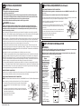
THREE-CONDUCTOR BRANCH CIRCUIT CONNECTION
NOTE: If residence leads are aluminum conductors, see WARNING in section 5A, Electrical Requirements.
When connecting to a three-conductor branch circuit, if local codes permit:
1. Connect the oven ground conductor along with the neutral (white)
lead to the branch circuit neutral (white or gray in color), using a
wire nut.
2. Connect the oven red lead to the branch circuit red lead, and the
oven black lead to the branch circuit black lead in accordance with
local codes, using wire nuts.
3. Install proper strain relief clamp.
4. Install junction box cover.
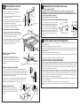
5
ELECTRICAL REQUIREMENTS (Continued)
FOUR-CONDUCTOR BRANCH CIRCUIT CONNECTION
NOTE: If residence leads or ground are aluminum conductors, see WARNING in section 5A, Electrical
Requirements.
When connecting to a four-conductor branch circuit, if local codes permit:
1. Free the neutral (white) lead from being restrained to any other wires. If necessary, cut the neutral
(white) lead and then re-strip it to expose the proper length of conductor.
2. Attach the appliance grounding lead (green or bare copper)
in accordance with local codes.
3. Connect the oven neutral (white) lead to the branch circuit
neutral (white or gray) in accordance with local codes, using
a wire nut.
4. Connect the oven red lead to the branch circuit red lead and
the oven black lead to the branch circuit black lead in ac cor-
dance with local codes, using wire nuts.
5. Install proper strain relief clamp.
6. Install junction box cover.
6
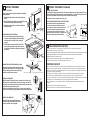
ANTI-TIP DEVICE INSTALLATION
WARNING
• To reduce the risk of tipping the range, the range must be properly secured to the countertop or
rear wall using the anti-tip suppport. (See section 3 for details.)
• Weight on the door could potentially cause the range to tip and result in injury. Never allow
anyone to climb, sit, stand, or hang on the oven door.
Installing the Anti-Tip
Bracket
The anti-tip bracket is
attached to the back
of the Drop-In Range.
It is designed to fit
under the bottom
of the countertop
opening at the rear.
Measure counter
thickness at back of
cutout to determine
correct bracket
location.
Select the proper
position for the
countertop thickness
and move bracket to
proper position. (Unit
is sup plied with brack-
et in
po si tion 1.)
1 For 1.18” (3 cm)
Counter
2 For 1.5” Counter
3 For 3.5” Counter
4 Alternate (shown)
31-11041 08-16 GEA
Branch
circuit
Black
Alternate
knockout
Range conduit
snaps into box
Red
White
Ground
wires
ANTI-TIP INSTALLATION
Interior wall
1/4”
min. flat
area
Wall stud
Countertop
thickness
Bottom of
countertop
Wire cover
Maintop
Anti-tip
bracket
Bottom of
countertop
to engage
bracket by
1/2” min.
Wall stud
10-3/8”
1-1/2”
Countertop
surface
Interior wall
Wire
cover
Attachment
anchored to
wall stud is
required
Anti-tip bracket
Attachment
Non-kit ap pli ca tion
Maintop
Position
#5 non-kit
application
*Attachment
to engage
bracket by 1/2” min.
Anti-tip bracket location
(rear of range)
Cooktop
Branch
circuit
Black
Alternate
knockout
Neutral wire
connection
Range
conduit
snaps
into box
Red
Ground and
neutral wires
(white)
Tape or
Crimp

7
INSTALL THE RANGE
INSTALL STOP SCREW
These screws prevent the range from sliding out of position
during operation.
1. Carefully mark the cabinet for the location of the stop
screws.
2. Drill 1/8” pilot holes into cabinet, on each side of the range.
(Do not drill entirely through the cabinet wall.)
3. Carefully turn the shoulder screws into the pilot holes
until they are tight.
PLACING RANGE INTO THE OPENING
1. It is recommended that two people lift the range
into place, carefully setting the side metal flanges
under the glass on the edges of the countertop
opening.
2. Carefully slide the range toward the back of the
opening. Stop pushing the range when there is till
a 4” gap at the front before flushing the range with
the counter.
REMOVE THE PROTECTIVE CHANNELS (if provided)
Carefully remove the protective channels from the
sides of the glass cooktop. This may require a slight
lifting of the range to remove the weight of the
range from the protective channels.
CHECK ANTI-TIP BRACKET
With the range still sitting out from the counter-top, confirm the anti-
tip bracket is securely attached to the rear of the range, and slide the
range back so that the anti-tip bracket slides just under the countertop
or wood block attached to the rear wall.
If the range is pulled from the wall for any reason, always repeat this
procedure to verify the range is properly secured by the anti-tip bracket.
ATTACH THE LOWER TRIM
Attach the lower trim (supplied separately
with the range) to the bottom of the vertical
side trim with the 4 screws supplied.
7
INSTALL THE RANGE (Continued)
LOCATING THE STOP SCREW
Carefully slide the range towards the back of the opening. When the range is approximately 1” from
the back of the opening, lift the front of the range approximately ½” to clear the stop screw located
in the sides of the cabinet. Slide the range until it is seated into the opening.
Lower the front of the range onto the counter-top.
CHECK FOR PROPER INSTALLATION OF THE STOP SCREW
Look at both sides of the range under the door.
The stop screws must be located in the notch
on the sides of the range, and not touch the top
of the notch when the range is fully seated on
the countertop. If the screws do not meet the
requirements, move the screws to a position that
meets these requirements. (See illustration.)
Gap Approx. 4”
Gap Approx. 4”
Countertop
Glass Cooktop
Protective Cover
Remove Protective Cover from Both Sides after Range is in Cabinet
Oven
Anti-Tip Bracket
Countertop or
Wood Block
Side
trim
Lower
Trim
Lower
right
end of
front
frame
Attach 2
screws
each
side
Clear
Lower
Trim
Shoulder Screw
Notch in Bottom
of Side Trim
8
FINAL INSTALLATION CHECKLIST
• Check to make sure the circuit breaker is closed (RESET) or the circuit fuses are replaced.
• Be sure power is in service to the building.
•
Check that all packing material and tape have been removed. Failure to remove these materials could result
in damage to the appliance once the appliance has been turned on and surfaces have heated.
• Remove all items from inside the oven.
• Confirm that anti-tip device has been properly installed (see Section 6).
• Check that the bottom trim is installed properly (see Section 7).
OPERATION CHECKLIST
• Turn on one of the surface units to observe that the element glows within 60 seconds. Turn the unit
off when glow is detected. If the glow is not detected within the time limit, recheck the range wiring
connections. If change is required, retest again. If no change is required, have building wiring checked
for proper connections and voltage.
• Check that the Clock display is energized. If a series of horizontal red lines appear in the display,
disconnect power immediately. Recheck the range wiring connections. If change is made to
connections, retest again. If no change is required, have building wiring checked for proper connections
and voltage. It is recommended that the clock be changed if the red lines appear.
• Turn on the power to your oven(refer to Owner’s manual). Verify that the bake and broil operate
properly.
• See your owner’s manual for trouble shooting list.
• Be sure all of the oven controls are OFF before leaving the oven.

2
PREPARE LA ABERTURA (SÓLO PARA USO EN EL INTERIOR)
NOTA: Las cocinas empotrables son diseñadas para colgar de la base únicamente. No instale sobre
una plataforma de rieles con soportes.
ANTES DE COMENZAR
Lea estas instrucciones por completo y con
detenimiento.
• IMPORTANTE ³ Guarde estas
instrucciones para el uso de inspectores locales.
• IMPORTANTE ³ Cumpla con todos los
códigos y ordenanzas vigentes.
• Nota al instalador –Asegúrese de dejar estas
instrucciones con el consumidor.
• Nota al consumidor – estas instrucciones para
referencia futura.
• Nivel de destreza – La instalación de este
aparato requiere el trabajo de un instalador o
electricista calificados.
• El instalador tiene la responsabilidad de
efectuar una instalación adecuada.
• La garantía no cubre las fallas del producto
provocadas por una instalación incorrecta.
PARA SU SEGURIDAD
Si no recibió un soporte anti-volcaduras con su compra, llame al
1.800.626.8774 para recibir uno sin costo. (En Canadá, llame al
1.800.561.3344). Para recibir instrucciones de instalación
del soporte, visite: GEAppliances.com
(En Canadá, GEAppliances.ca.).
Instrucciones de instalación
Cocinas encastrables de 30”
MATERIALES QUE PUEDE
NECESITAR
HERRAMIENTAS NECESARIAS
Caja de conexiones
Tapones de alambre
Abrazadera de alivio de tensión para
conducto de 1/2”
1
QUITE LOS MATERIALES DE EMPAQUE No quitar los materiales de empaque
puede provocar daños al electrodoméstico.. Quite la película protectora y las etiquetas de la
puerta exterior y panel de control. Además, quite el plástico de los rebordes y panel y toda la cinta
colocada alrededor del horno. Abra la puerta del horno y quite el material informativo y las
bandejas del horno. Quite el reborde inferior de la parte lateral del horno. Se colocará al final del
proceso de instalación. El borde está envuelto de forma aparte en una bolsa plástica que también
contendrá 4 tornillos para asegurar el borde inferior y los tornillos de tope usados para asegurar
el producto al gabinete.
Broca de perforadora
de 1/8” y perforadora
eléctrical
Destornillador de estrella
Nivel
Destornillador con punta
plana
Cinta métrica
Llave de tuercas de 1/4”
Punta derecha o cuadrada
Martillo
Sierra de mano o sierra
sable
Lápiz
Gafas de Seguridad
• Un niño o adulto pueden volcar la cocina y morir.
• Instale el soporte anti-volcaduras sobre la pared o el piso.
•
Asegúrese la estufa al soporte anti-volcaduras deslizando
la unidad hacia atras de tal manera que la pata niveladora
sea enganchada.
• Vuelva a adherir el soporte anti-volcaduras si la estufa
se mueve de lugar.
• Si esto no se hace, se podrá producir la muerte o
quemaduras graves en niños o adultos.
Riesgo de Caída
ADVERTENCIA
¿Preguntas? Llame al 1.800.GE.CARES (1.800.432.2737) o visite www.GEAppliances.com
En Canadá, llame al 1.800.561.3344 o visite www.GEAppliances.ca.
ADVERTENCIA³
Antes de
comenzar la instalación, desconecte la
energía del panel de servicio y bloquee
los medios de desconexión para evitar
el accionamiento de la energía de
manera accidental. Cuando los medios
de desconexión de servicio no pueden
bloquearse, coloque sobre el panel de
servicio un dispositivo de advertencia
bien visible, como una etiqueta.
Hornov
Soporte Anti-Volcaduras
Base o Bloque
de Madera
Pared
Trasera
Profundidad total
de 26-1/2”
5-5/8” Bobina
2-7/8” Radiante
hasta la superficie
frontal de la base
20-5/8”
Espacio hasta
la puerta desde
la superficie
de la base
Franjas
de protección
(si se suministran)
Relleno
del gabinete
frontal
(si se requiere)
Soportes
del relleno
de la parte
frontal
Mín. de 27-1/2”
30”
Siga las instrucciones embaladas
con los electrodomésticos alternativos.
(Se deberá mantener una dim. mín.
de 24" entre la superficie de la cocina
y el lado inferior del electrodoméstico)
Mín. de 30”
Muestra
del Tablero
Posterior
Preformado
Profundidad
máx. de 13”
Distancia vertical mín. 15”
desde la parte inferior
de los gabinetes adyacentes
elevados
Profundidad
de la base
de 25”
Mín. de 1-1/4”
desde la base
a la parte superior
del cajón
9/16”
Mín. de 29 15/16”
Máx. de 30 1/16”
Para una instalación óptima,
estas superficies deberá
ser planas y estar a nivel
Área del
tomacorrientes
eléctrico
aceptable.
También en
el gabinete
adyacente o
debajo del piso
1/4”
plano
Mín. de 30”
desde la
superficie
de cocina
hasta la parte inferior
de los gabinetes elevados
Se recomienda un mín.
De 6” desde las paredes
23-3/16”
Afeitar borde levantado
para eliminar 31-1/8 "
de ancho del panel
Mín. de 28 1/2"
desde la parte
superior de la mesada
Deje un espacio mínimo de 30” entre las unidades de la
superficie y la parte inferior del gabinete de madera o metal
sin protección. Deje un espacio mínimo de 24” cuando la parte
inferior de la madera o metal estén protegidas por cartón de
retardo de incendios de 1/4” de grosor, cubierto con no menos
que una hoja de acero inoxidable Nº 28 MGS de 0.15”, de
aluminio de 0.24” o de cobre de .020” de grosor.

2
PREPARE LA ABERTURA (SÓLO PARA USO EN EL INTERIOR)
(Continuación)
3
CUANDO INSTALE LA COCINA EN UN MOSTRADOR QUE TIENE
UN RECORTE EN LA PARED
Si la abertura de la base se extiende hasta las paredes, se requerirá un kit de relleno de la base de
la parte superior WB07T1068X o un kit de protección trasera JXS32XX para cerrar la brecha. Para
acceder a detalles de la instalación, consulte el kit de relleno o de protección trasera.
NOTA: Si la base es superior a 25”, mostrará una brecha entre la protección trasera y la pared o entre
el kit de relleno y la pared.
ADVERTENCIA Se deberá montar un soporte anti-volcaduras adicional sobre la pared
trasera de la abertura. El soporte anti-volcaduras es típicamente una pieza de madera de 2 x 4 que
se atornilla directamente en montajes de pared. El soporte anti-volcaduras deberá poder resistir 200
libras de fuerza en el punto de adhesión.
4
QUITE LA PUERTA DEL HORNO
No es un requisito que se retire la puerta para la instalación del producto, pero es conveniente. Para
retirar la puerta:
1. Abra la puerta del horno tanto como sea posible.
2. Empuje ambas trabas de las bisagras hacia el marco de la puerta hasta la
posición destrabada. Esto podrá requerir el uso de un destornillador de punta
plana.
3. Coloque las manos sobre ambos lados de la puerta, y cierre la misma en la posición
para su retiro. Esto se encuentra entre la posición de detenimiento
de la función de asar a la parrilla y totalmente cerrado.
4. Levante la puerta hacia arriba y afuera, hasta que los brazos de
las bisagras despejen las ranuras.
La Instalación Estándar de esta Estufa Empotrable es
colgando de la base sobre la pestaña metálica lateral
debajo de la cocina de vidrio. Esta Estufa no deberá
ser instalada sobre una base o subestructura
(soporte de 2” x 4”).
Si la construcción de su gabinete no puede brindar un área plana de ¼” en la parte trasera
de la abertura de la base, considere la posibilidad de cambiar la base para que se acomode a
esta dimensión. Si el área no es plana, se podrá aplicar tensión excesiva a la cocina de vidrio,
ocasionando roturas y anulando la garantía.
• Se requiere un grosor de la base mín. de 1-1/4” para el soporte del producto. Se deberán instalar
abrazaderas entre el lado inferior de la base y el gabinete, si se requiere obtener un grosor mín.
de 1-1/4” (en cada lado).
• Asegúrese de que los cobertores de pared, bases y gabinetes alrededor del horno puedan resistir
el calor (hasta 200º F/ 93.3º C) generado por el horno.
• Este aparato ha sido aprobado para un espacio de 0” respecto de superficies adyacentes sobre
la estufa. Sin embargo, se recomienda un espacio mínimo de 6” respecto de superficies menores
a 15” sobre la estufa y gabinete adyacente para reducir la exposición al vapor, salpicaduras de
grasa y calor.
• Ubique una caja de conexiones de cableado en la parte trasera del recorte. La dimensión desde la
parte superior de la caja de conexiones hasta el mostrador debe ser de un mínimo de 28-1/2”. La
caja no debe extenderse más de 3” del plano de la pared. La caja de conexiones debe ubicarse en
un lugar en donde permita una holgura considerable en el conducto de la cocina, para que ésta
pueda moverse a fin de efectuar reparaciones si fuera necesario.
Hinge Lock
(Unlocked
Position)
Hinge
Slot
Hinge Arm
Hinge
Clears Slot
Pared
Mín. de ¼”
plano
23-3/16”
Min. de 9/16”
plano
Mín. de 9/16”
plano
Corte parejo de
29-15/16”-30-1/16”
Típicamente
de 25”
1/4”
R
Área
plana
Base
Soporte de la estufa
Mín. de 29 -15/16”
Máx. de 30 -1/16”
10-3/8” desde
la mesada hasta
el soporte
anti-volcaduras
25”
9/16”
9/16”
Deberá ser plana
Deberá ser plana
Soporte
anti-volcaduras
Pared

5
REQUISITOS ELÉCTRICOS
ADVERTENCIA Riesgo de descarga eléctrica
• Este aparato debe contar con una adecuada conexión a tierra.
• No utilice un cable de extensión.
• Antes de comenzar la instalación, desconecte la energía del panel de servicio y bloquee los medios de
desconexión para evitar el accionamiento de la energía de manera accidental. Cuando los medios de
desconexión de servicio no pueden bloquearse, coloque sobre el panel de servicio un dispositivo de
advertencia bien visible, como una etiqueta.
No seguir estas instrucciones puede provocar una lesión grave o la muerte.
ADVERTENCIA Riesgo de incendio
Una conexión inadecuada de cableado doméstico de aluminio con cables de cobre puede generar
un peligro eléctrico o un incendio. Si los cables domésticos son de aluminio, sólo use conectores
diseñados para unir cobre con aluminio y siga al pie de la letra el procedimiento recomendado del
fabricante. No hacerlo puede provocar una lesión grave o la muerte.
Recomendamos que un electricista calificado conecte el cableado eléctrico de su aparato. Después de la
instalación, solicite al electricista que le indique cómo desconectar la energía del aparato.
Usted debe usar un sistema eléctrico de fase única de 120/208 VAC o 120/240 VAC de 60 hercios.
Vigente desde el 1 de enero de 1996, el Código Eléctrico Nacional requiere que las nuevas construcciones
(no existentes) utilicen una conexión de cuatro conductores a un horno eléctrico. Cuando instale un horno
eléctrico en una construcción nueva, una casa rodante, un vehículo recreativo o un área donde los códigos
locales prohíben la conexión a tierra a través de un conductor neutral, consulte la sección sobre conexiones en
circuito derivado de cuatro conductores.
Consulte a las empresas de servicio público sobre los códigos eléctricos que se aplican en su área. No realizar
el cableado de su horno de acuerdo con los códigos vigentes puede provocar una situación peligrosa. Si no
existen códigos locales, el cableado y fusibles de su horno deben cumplir con el Código Eléctrico Nacional,
NFPA Nº 70, última edición, disponible en National Fire Protection Association (Asociación Nacional de
Protección contra Incendios).
La placa de clasificación se encuentra en el armazón frontal del horno y es visible cuando se abre la puerta del horno.
Este electrodoméstico debe recibir el voltaje y frecuencia adecuados, y debe conectarse a un circuito derivado
individual con adecuada conexión a tierra de 40 amperios (mínimo) protegido por un interruptor de circuitos o
fusible con retraso.
NO acorte el conducto flexible. La abrazadera del alivio de tensión del conducto debe estar bien sujeta a la
caja de conexiones y el conducto flexible debe estar bien sujeto a la abrazadera. Si el conducto flexible no
entra dentro de la abrazadera, no instale el horno hasta obtener una abrazadera del tamaño adecuado.
Los 3 cables de energía suministrados con este aparato son adecuados para conexiones con cableados
domésticos de calibre mayores. La aislación de estos 3 cables está clasificada a temperaturas mucho más
elevadas que la clasificación del cableado doméstico. La capacidad de transmitir corriente del conductor está
determinada por el calibre del cable y la clasificación de temperatura de la aislación alrededor del cable.
REALICE LAS CONEXIONES ELÉCTRICAS
Coloque el horno sobre una mesa o plataforma en forma nivelada con la abertura. La plataforma debe poder
soportar 200 lbs. (91 kg). Conecte el conducto flexible a la caja de conexiones eléctrica como se indica abajo.
CONEXIÓN DE CIRCUITO DERIVADO DE TRES CONDUCTORES
NOTA: Si los cables del hogar poseen conductores de aluminio, ver la
ADVERTENCIA de la sección 5a, Requisitos eléctricos.
Cuando conecte un circuito derivado de cuatro conductores, si lo
permiten los códigos locales:
1. Conecte el conductor de conexión a tierra junto con el cable neutro
(blanco) al neutro del circuito de empalmes (de color blanco o gris),
usando una tuerca para cables.
2. Conecte el cable rojo del horno al cable rojo del circuito derivado y el
cable negro del horno al cable negro del circuito derivado de acuerdo
con los códigos locales, utilizando tapones de alambre.
3. Instale una abrazadera adecuada de alivio de tensión.
4. Instale la tapa de la caja de conexiones.
5
REQUISITOS ELÉCTRICOS (Continuación)
CONEXIÓN DE CIRCUITO DERIVADO DE CUATRO CONDUCTORES
NOTA: Si los cables domésticos o de conexión a tierra son conductores de aluminio, ver la
ADVERTENCIA de la sección 5a, Requisitos eléctricos.
Cuando conecte un circuito derivado de cuatro conductores, si lo permiten los códigos locales:
1. Evite que el conductor neutro (blanco) quede enredado con cualquier otro cable. De ser necesario,
corte el conductor neutro (blanco) y luego vuelva a pelar el mismo, a fin de exponer la longitud
adecuada del conductor.
2. Conecte el cable a tierra del aparato (verde o cobre) de acuerdo
con los códigos locales.
3. Conecte el cable neutral (blanco) del horno con el neutral de
circuito derivado (blanco o gris) de acuerdo con códigos locales,
utilizando un tapón de alambre.
4. Conecte el cable rojo del horno al cable rojo del circuito derivado
y el cable negro del horno al cable negro del circuito derivado de
acuerdo con los códigos locales, utilizando tapones de alambre.
5. Instale una abrazadera adecuada de alivio de tensión.
6. Instale la tapa de la caja de conexiones.
6
INSTALACIÓN DEL DISPOSITIVO ANTI-VOLCADURAS
ADVERTENCIA
• A fin de reducir el riesgo de volcaduras de la estufa, la misma deberá estar correctamente
asegurada a la base o la pared trasera usando un soporte anti-volcaduras. (Para más detalles,
consulte la sección 3).
• El peso sobre la puerta podría
potencialmente hacer que
la estufa se vuelque y que
esto produzca lesiones.
Nunca permita que
nadie se trepe siente,
pare ni cuelgue de
la puerta del horno.
Instalación de los
Soportes Anti-Volcaduras
El soporte anti-
volcaduras
se encuentra adherido
a la parte trasera de
la Cocina Empotrable.
Fue diseñado para su
ubicación debajo de
la abertura de la base en
la parte trasera. Mida el grosor de la base
en la parte trasera de la abertura para determinar
la ubicación correcta del soporte.
Seleccione la posición correcta de acuerdo
al grosor de la base y mueva el soporte hasta
la posición adecuada. (La unidad se entrega con
el soporte en la posición 1).
1 Para una base de 1.18” (3 cm.)
2 Para una base de 1.5”
3 Para una base de 3.5”
4 Alternativa (se muestra a continuación)
Circuito
ramificado
Negro
Agujero ciego
alternativo
El tubo de
la estufa
se ajusta
en la caja
Rojo
Blanco
Cables
a tierra
INSTALACIÓN ALTERNATIVA DEL DISPOSITIVO
ANTI-VOLCADURAS
INSTALACIÓN DEL DISPOSITIVO
ANTI-VOLCADURAS
Pared interior
Espacio plano
mín. de 1/4”
Montaje
de pared
Grosor de
la base
Parte
inferior de
la base
Cubre
cables
Base en la parte
superior
Soporte anti-
volcaduras
Parte
inferior del
soporte anti-
volcaduras
para colocar
el soporte
a un mín.
de ½”
Montaje de pared
10-3/8”
1-1/2”
Superficie de
la mesada
Pared interior
Cubre
cables
Se requiere
colocar la
adhesión al
montaje de
pared
Soporte anti-
volcaduras
Adhesión
Aplicación sin kit
Base en
la parte
superior
Aplicación
sin kit en
posición 5
* Adhesión para colocar el
soporte a un mín. de ½”
UBICACIÓN DEL SOPORTE ANTI-VOLCADURAS
(PARTE TRASERA DE LA COCINA)
Estufa
31-11041 08-16 GEA
Circuito
ramificado
Negro
Agujero
ciego
alternativo
Cable neutral
conexión
Encinte o
Prense
El tubo de
la estufa
se ajusta
en la caja
Rojo
Cables a
tierra y
neutrales
(blanco)

7
INSTALACIÓN DE LA COCINA
INSTALACIÓN DEL TORNILLO DE DETENCIÓN
Estos tornillos evitan que la cocina se mueva de su
posición durante el funcionamiento.
1. Con cuidado, marque en el gabinete la ubicación de
los tornillos de detención.
2. Haga agujeros de prueba de 1/8” en el gabinete,
sobre cada lado de la cocina. (No haga el agujero
atravesando la pared del gabinete).
3. Con cuidado, gire los tornillos de tope en los agujeros
de prueba hasta que queden ajustados.
COLOCACIÓN DE LA COCINA EN LA ABERTURA
1. Es recomendable que dos personas levanten la
estufa hasta su ubicación, colocando con cuidado las
pestañas metálicas laterales debajo del vidrio sobre
los extremos de la abertura de la base.
2. Con cuidado, deslice la cocina hacia la parte trasera
de la abertura. Deje de empujar la cocina cuando
aún haya un espacio de 4” en el frente, antes de
colocar la cocina al ras de la base.
RETIRE LOS CANALES PROTECTORES
(si están incluidos)
Con cuidado retire los canales protectores a
ambos lados de la estufa de vidrio. Es posible que
sea necesario levantar levemente la cocina, a fin
de quitar el peso de la cocina sobre los canales
protectores.
CONTROLE EL SOPORTE ANTI-VOLCADURAS
Con la cocina aún apoyada en parte afuera de la punta de la base,
confirme que el soporte anti-volcaduras esté ajustado de forma segura
a la parte trasera de la cocina, y vuelva a deslizar esta última de modo
que el soporte anti-volcaduras se deslice debajo de la base o del bloque
de madera ajustado a la pared trasera.
En caso de que la cocina sea empujada de la pared por alguna razón,
siempre repita este procedimiento para verificar que la cocina esté
correctamente asegurada por el soporte anti-volcaduras.
ADHIERA DEL BORDE INFERIOR
Adhiera el borde inferior (suministrado en
forma aparte con la cocina) a la parte inferior
del borde del lado vertical con los 4 tornillos
provistos.
7
INSTALACIÓN DE LA COCINA (Continuación)
UBICACIÓN DEL TORNILLO SUPERIOR
Con cuidado, deslice la cocina hacia la parte trasera de la abertura. Cuando la cocina esté
aproximadamente a 1” de la parte trasera de la abertura levante la parte frontal de la cocina
aproximadamente ½” para retirar el tornillo superior ubicado a ambos lados del gabinete. Deslice la
cocina hasta que se ubique en la abertura.
Baje la parte frontal de la cocina sobre la base.
CONTROLE QUE LA INSTALACIÓN DEL TORNILLO SUPERIOR SEA ADECUADA
Controle ambos lados de la cocina debajo de la
puerta. Los tornillos superiores deberán estar
ubicados en el agujero sobre los costados de la
cocina, y no tocar la parte superior del agujero
cuando la cocina se encuentre totalmente ubicada
sobre la base. Si los tornillos no cumplen con los
requisitos, mueva los mismos a una posición de
modo que cumplan con los requisitos. (Vea la
ilustración).
26-1/4” desde
la base hasta
la línea central
del tornillo
2-1/2” desde
el extremo
frontal de
la base hasta
la línea
central
del tornillo
Un tornillo sobr
e
cada lado
Espacio de 4” aprox.
Espacio de 4” aprox.
Base
Hornov
Soporte Anti-Volcaduras
Base o Bloque
de Madera
Pared
Trasera
Borde
lateral
Borde
inferior
Extremo
inferior
derecho
del
marco
frontal
Agregue
2 tornillos
a cada
lado
Clear
Borde
inferior
Tornillo de tope
Agujero en la
parte inferior del
borde lateral
Estufa de vidrio
Tapa protectora
Retire la tapa protectora a ambos lados una vez que la cocina esté
en el gabinete.
EMPUJE
8
LISTA DE CONTROL FINAL DE LA INSTALACIÓN
• Verifique que el interruptor de circuitos se encuentre cerrado (RESET) o que los fusibles del circuito se
hayan reemplazado.
• Asegúrese de que haya suministro eléctrico en el edificio.
•
Controle que se haya quitado todo el material de empaque y la cinta adhesiva. No quitar estos materiales
puede provocar daños al electrodoméstico una vez que el aparato se haya encendido y las superficies se
hayan calentado.
• Quite todos los elementos ubicados dentro del horno.
• Confirme que el dispositivo anti-volcaduras haya sido instalado de forma correcta (consulte la Sección
6).
• Verifique que el reborde inferior esté bien instalado (ver sección 6).
LISTA DE CONTROL DE FUNCIONAMIENTO
• Accione una de las unidades de superficie para observar que el elemento se encienda dentro de los 60
segundos. Apague la unidad cuando se detecte el encendido. Si no se detecta el encendido dentro del
límite de tiempo, vuelva a verificar las conexiones del cableado de la cocina. Si se requiere un cambio,
vuelva a probar el aparato. Si no se requiere un cambio, haga controlar el cableado del edificio para
verificar las conexiones y voltaje adecuados.
• Controle que la pantalla del reloj se haya encendido. Si en la pantalla aparece una serie de líneas rojas
horizontales, desconecte la energía de inmediato. Vuelva a controlar las conexiones del cableado de
la cocina. Si se efectúa un cambio en las conexiones, vuelva a probar el aparato. Si no se requiere un
cambio, haga controlar el cableado del edificio para verificar las conexiones y voltaje adecuados. Se
recomienda cambiar el reloj si aparecen las líneas rojas.
• Accione la energía del horno (consulte el Manual del propietario). Verifique que el horneado y el asado
funcionen correctamente.
• Ver el Manual del propietario para la lista de detección y solución de problemas.
• Asegúrese de que todos los controles del horno se encuentren en OFF (apagado) antes de dejar el
horno.
-
 1
1
-
 2
2
-
 3
3
-
 4
4
-
 5
5
-
 6
6
-
 7
7
-
 8
8


GE JD630DFBB Guía de instalación
- Tipo
- Guía de instalación
en otros idiomas
- English: GE JD630DFBB Installation guide
Artículos relacionados
-
GE JD630SFSS Guía de instalación
-
GE JD750DFBB Guía de instalación
-
-
GE JM250DFWW Guía de instalación
-
GE JM250DTWW Guía de instalación
-
-
GE Appliances JSP46SPSS Guía de instalación
-
GE Profile P2S975SEPSS Instrucciones de operación
-
GE JS630DFBB Guía de instalación
-