El GE JD750DFBB es una cocina eléctrica de 30 pulgadas con cuatro quemadores y un horno de convección. Los quemadores tienen una amplia gama de configuraciones de calor, lo que los hace ideales para cocinar a fuego lento o hervir. El horno de convección cocina los alimentos de manera uniforme y rápida, y también cuenta con una función de asado. La cocina también tiene una función de limpieza automática, que facilita la limpieza.
El GE JD750DFBB es una cocina eléctrica de 30 pulgadas con cuatro quemadores y un horno de convección. Los quemadores tienen una amplia gama de configuraciones de calor, lo que los hace ideales para cocinar a fuego lento o hervir. El horno de convección cocina los alimentos de manera uniforme y rápida, y también cuenta con una función de asado. La cocina también tiene una función de limpieza automática, que facilita la limpieza.


-
 1
1
-
 2
2
-
 3
3
-
 4
4
-
 5
5
-
 6
6
-
 7
7
-
 8
8
-
 9
9
-
 10
10
-
 11
11
-
 12
12
-
 13
13
-
 14
14
-
 15
15
-
 16
16
-
 17
17
-
 18
18
-
 19
19
-
 20
20
-
 21
21
-
 22
22
-
 23
23
-
 24
24


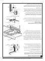
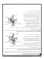
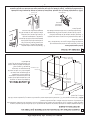
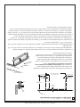
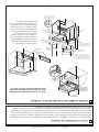
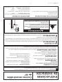
GE JD750DFBB Guía de instalación
- Tipo
- Guía de instalación
- Este manual también es adecuado para
El GE JD750DFBB es una cocina eléctrica de 30 pulgadas con cuatro quemadores y un horno de convección. Los quemadores tienen una amplia gama de configuraciones de calor, lo que los hace ideales para cocinar a fuego lento o hervir. El horno de convección cocina los alimentos de manera uniforme y rápida, y también cuenta con una función de asado. La cocina también tiene una función de limpieza automática, que facilita la limpieza.
en otros idiomas
- English: GE JD750DFBB Installation guide
Artículos relacionados
-
GE JD630SFSS Guía de instalación
-
-
-
GE JM250DFWW Guía de instalación
-
GE Appliances JSP46SPSS Guía de instalación
-
GE JM250DTWW Guía de instalación
-
GE Profile P2S975WEMWW Guía de instalación
-
-
-
GE JS630DFBB Guía de instalación