Sime Murelle Equipe 220 660 ErP El manual del propietario
- Tipo
- El manual del propietario

MURELLE EQUIPE 220-660 ErP
(PACK OF 2-6 MURELLE HE 110 R ErP)
199839
INSTALLATION AND SERVICING INSTRUCTIONS
ENSURE THAT THESE
INSTRUCTIONS ARE LEFT
FOR THE USER AFTER
COMPLETION OF THE
BENCHMARK SECTION
PLEASE READ THE
IMPORTANT NOTICE
WITHIN THIS GUIDE
REGARDING YOUR BOILER
WARRANTY
UK
Cod. 6328543 - 07/2019
ORIGINAL INSTRUCTIONS

This boiler may require 2 or more operatives to move it into its installation site, remove it from its packaging and
during movement into its installation location. Manoeuvring the boiler may include the use of a sack truck and
involve lifting pushing and pulling.
Caution should be exercised during these operations.
Operatives should be knowledgeable in handling techniques when performing these tasks and the following pre-
cautions should be considered:
– Grip the boiler at the base
– Be physically capable
– Use personal protective equipment as appropriate e.g. gloves, safety footwear.
During all manoeuvres and handling actions, every attempt should be made to ensure the following unless unavoi-
dable and/or the weight is light.
– Keep back straight
– Avoid twisting at the waist
– Always grip with the palm of the hand
– Keep load as close to the body as possible
– Always use assistance
WARNING
Caution should be exercised when performing any work on this appliance.
Protective gloves and safety glasses are recommended.
– Avoid direct contact with sharp edges.
– Avoid contact with any hot surfaces.
NOTICE
Please be aware that due to the wet testing of the appliance, there may some residual water in the hydraulic circuit.
– Protect any surfaces, carpets or floorings.
– Use a suitable container to catch any water that escape when removing the protective caps from the connections.
SAFE HANDLING

All descriptions and illustrations provided in this manual have been carefully prepared but we reserve the right to make
changes and improvements in our products that may affect the accuracy of the information contained in this manual.
Please refer to commissioning instructions for filling in the checklist at the back of this installation guide.
Note: All Gas Safe registered installers carry a ID Card.
You can check your installer is Gas Safe Registered by calling 0800 408 5577
CONTENTS
1 MODULAR SYSTEM DESCRIPTION ............................................................................................................. page 4
2 FRAME ASSEMBLY OF SINGLE MODULE SUPPORT .................................................................................. page 17
3 FITTING CONNECTION AND CONDENSATE DRAIN ................................................................................... page 19
4 ASSEMBLE THE CASCADE FLUE ................................................................................................................ page 24
5 CASCADE CONNECTION ............................................................................................................................. page 25
6 CASCADE MANAGEMENT ........................................................................................................................... page 26
7 APPENDIX (GUIDANCE HHIC) ..................................................................................................................... page 31
8 APPENDIX 2 (VENTILATION GUIDENCE) .................................................................................................... page 45
9 PRODUCT DETAILS ........................................................................................................................................ page 46
10 ANNEX AA.1 ................................................................................................................................................... page 47
IMPORTANT
Prior to switching on the boiler for the first time, check the following:
– Make sure that there are no liquids or inflammable materials in the immediate vicinity of the boiler.
– Make sure that the electrical connections have been made correctly and that the earth wire is connected
to a good earthing system.
– Ensure that tightness and let by test have been conducted, including the internal gas pipe work.
– Make sure that the boiler is set for operation for the type of gas supplied.
– Check that the flue pipe for the outlet of the products of the combustion is unobstructed and has been
properly installed.
– Make sure that any isolation valves are open.
– Make sure that the system is filled with water and is thoroughly vented.
– Check that the circulating pump is not jammed.
– Purge the gas supply pipe work.
– Ensure that the checklist is filled in when the commissioning has been completed.
IPX4D
Important Information
IT IS A STATUTORY REQUIREMENT THAT ALL GAS APPLIANCES ARE INSTALLED BY COMPETENT PERSONS,
IN ACCORDANCE WITH THE GAS SAFETY (INSTALLATION AND USE) REGULATIONS (CURRENT EDITION).
The manufacturer’s instructions must not be taken as overriding any statutory requirements, and failure
to comply with these regulations may lead to prosecution.
No modifications to the appliance should be made unless they are fully approved by the manufacturer.
GAS LEAKS: DO NOT OPERATE ANY ELECTRICAL SWITCH, OR USE A NAKED FLAME. TURN OFF THE GAS
SUPPLY AND VENTILATE THE AREA BY OPENING DOORS AND WINDOWS CONTACT THE GAS EMERGENCY
SERVICE ON 0800111999.

4
1.1 INTRODUCTION
This manual is for the construction main-
tenance and operation of a modular unit
composed of multiple premixed conden-
sation boilers in the MURELLE EQUIPE
220-660 ErP series linked in sequence/
cascade independently of one another.
The packages are provided with the fol-
lowing codes:
– MURELLE EQUIPE 220 ErP
Boilers and Mounting Frames and He-
aders code 9001220
Low Loss Header Connection Kit code
8101532
Low Loss Header code 8101552
Cascade Flue code 9000220
– MURELLE EQUIPE 330 ErP
Boilers and Mounting Frames and He-
aders code 9001330
Low Loss Header Connection Kit code
8101532
Low Loss Header code 8101552
Cascade Flue code 9000330
– MURELLE EQUIPE 440 ErP
Boilers and Mounting Frames and He-
aders code 9001440
Low Loss Header Connection Kit code
8101533
Low Loss Header code 8101553
Cascade Flue code 9000440
– MURELLE EQUIPE 550 ErP
Boilers and Mounting Frames and He-
aders code 9001550
Low Loss Header Connection Kit code
8101533
Low Loss Header code 8101553
Cascade Flue code 9000550
– MURELLE EQUIPE 660 ErP
Boilers and Mounting Frames and He-
aders code 9001660
Low Loss Header Connection Kit code
8101533
Low Loss Header code 8101553
Cascade Flue code 9000660
VENTILATION, for guidance see APPEN-
DIX 2.
1 MODULAR SYSTEM DESCRIPTION
1.2 DIMENSIONS AND FITTINGS
Note: The low loss header and flue can be positioned to exit at either the left or right hand side.
1.2.1 MURELLE EQUIPE 220-330 ErP (fig. 1/a)
DIMENSIONS
Murelle Equipe 220 ErP 330 ErP
L mm 1104 1656
H mm 2292 2326
D mm 200 200
620
374
131
155
155
131
374
620
260
555
ø D
ø D
MURELLE EQUIPE 220-330 UK
MURELLE EQUIPE 440-550 UK
1780
L
260
380
296
470
S3
G
M
R
1780
260
555
635
551
L
590
500
M
R
S3
G
H
H
Fig. 1/a
FIXTURES
M C.H. flow (Flange PN6-DN100)
R C.H. return (Flange PN6-DN100)
G Gas (Flange PN6-DN50)
S3 Condensation drain ø 40

5
G
S3
M
R
131
374
620
3314
ø 250
500
590
550
635
2428
260
555
1780
154
Kit - 8101553
Kit - 8101533
1.2.3 MURELLE EQUIPE 660 ErP (fig. 1/c)
FIXTURES
M C.H. flow (Flange PN6-DN100)
R C.H. return (Flange PN6-DN100)
G Gas (Flange PN6-DN50)
S3 Condensation drain ø 40
Fig. 1/c
1.2.2 MURELLE EQUIPE 440-550 ErP (fig. 1/b)
Fig. 1/b
620
374
131
155
155
131
374
620
260
555
ø D
ø D
MURELLE EQUIPE 220-330 UK
MURELLE EQUIPE 440-550 UK
1780
L
260
380
296
470
S3
G
M
R
1780
260
555
635
551
L
590
500
M
R
S3
G
H
H
DIMENSIONS
Murelle Equipe 440 ErP 550 ErP
L mm 2208 2760
H mm 2360 2394
D mm 200 200
FIXTURES
M C.H. flow (Flange PN6-DN100)
R C.H. return (Flange PN6-DN100)
G Gas (Flange PN6-DN50)
S3 Condensation drain ø 40

6
1.3 TECHNICAL SPECIFICATIONS MURELLE EQUIPE 220-550 ErP
MURELLE EQUIPE 220 ErP 330 ErP 440 ErP 550 ErP
Heat output
Nominal (80-60°C) (Pn max) kW 211.2 (2 x 105.6) 316.8 (3 x 105.6) 422.4 (4 x 105.6) 528.0 (5 x 105.6)
Nominal (50-30°C) (Pn max) kW 229.2 (6 x 114.6) 343.8 (3 x 114.6) 458.4 (4 x 114.6) 573.0 (2 x 114.6)
Minimum (80-60°C) (Pn min) kW 21.1 21.1 21.1 21.1
Minimum (50-30°C) (Pn min) kW 23.6 23.6 23.6 23.6
Heat input (*)
Nominal (Qn max - Qnw max) kW 216.0 (2 x 108.0) 324.0 (3 x 108.0) 432.0 (4 x 108.0) 540.0 (5 x 108.0)
Minimum (Qn min - Qnw min) kW 21.6 21.6 21.6 21.6
Min/max operating yield (80-60°C) % 97.7/97.8 97.7/97.8 97.7/97.8 97.7/97.8
Min/max operating yield (50-30°C) % 109.1/106.1 109.1/106.1 109.1/106.1 109.1/106.1
Operating yield at 30% (40-30°C) % 108.1 108.1 108.1 108.1
Losses after shutdown to 50°C (EN 15502) W 548 821 1095 1369
MURELLE HE 110 R ErP generators n° 2 3 4 5
Feeding tension V-Hz 230-50 230-50 230-50 230-50
Absorbed power consumption (Qn max) W 516 (2 x 258) 774 (3 x 258) 1032 (4 x 258) 1290 (5 x 258)
Absorbed power consumption (Qn min) W 134 138 142 146
Absorbed power consumption modulating pump W 260 (2 x 130) 390 (3 x 130) 520 (4 x 130) 650 (5 x 130)
Electrical protection grade IPX4D IPX4D IPX4D IPX4D
Energy efficiency
Seasonal energy efficiency class of the heating system A A A A
Seasonal energy efficiency of the heating system % 93 93 93 93
Sound power of the heating system dB (A) --- --- --- ---
Single module temperature regulation °C 20/80 20/80 20/80 20/80
Water content modules l 36.3 55.9 72.6 92.2
Max operating pressure (PMS) bar (kPa) 5 (490) 5 (490) 5 (490) 5 (490)
Max operating temperature (T max) °C 85 85 85 85
Exhaust temperature at max flow rate (80-60°C) °C 86.2 86.2 86.2 86.2
Exhaust temperature at min flow rate (80-60°C) °C 74.6 74.6 74.6 74.6
Exhaust temperature at max flow rate (50-30°C) °C 61.6 61.6 61.6 61.6
Exhaust temperature at min flow rate (50-30°C) °C 49.2 49.2 49.2 49.2
Smokes flow min/max g/s 10.28/103.34 10.28/155.00 10.28/206.67 10.28/258.34
CO
2 at min/max flow rate (G20) % 9.0/9.0 9.0/9.0 9.0/9.0 9.0/9.0
CO2 at min/max flow rate (G31) % 10.2/10.2 10.2/10.2 10.2/10.2 10.2/10.2
NOx measured (EN 15502-1:2015) mg/kWh 22 22 22 22
Max. output pressure fumes manifold Pa 375 375 375 375
Max. pressure independent fumes Pa 428 428 428 428
PIN number 1312CM5614
Category II2H3P
Type B23-B53-B23P-B53P-C13-C33-C43-C53-C83
NOx emission class (EN 15502-1:2015) 6 (‹ 56 mg/kWh)
Nozzle
Number n° 1 1 1 1
Nozzle diameter (G20) ø 17.2 17.2 17.2 17.2
Nozzle diameter (G31) ø 9.8 9.8 9.8 9.8
Gas consumption at nominal/minimum output
Nominal (G20) m
3
/h 22.84 (2 x 11.42) 34.26 (3 x 11.42) 45.68 (4 x 11.42) 57.10 (5 x 11.42)
Minimum (G20) m
3
/h 2.28 2.28 2.28 2.28
Nominal (G31) kg/h 16.76 (2 x 8.38) 25.14 (3 x 8.38) 33.52 (4 x 8.38) 41.90 (5 x 8.38)
Minimum (G31) kg/h 1.68 1.68 1.68 1.68
Supply pressure (G20/G31) mbar (kPa) 20/37 (1.96/3.63) 20/37 (1.96/3.63) 20/37 (1.96/3.63) 20/37 (1.96/3.63)
(*) Heat input of the heating system measured using lower heating value (LHV)

7
1.4 TECHNICAL SPECIFICATIONS MURELLE EQUIPE 660 ErP
MURELLE EQUIPE 660 ErP
Heat output
Nominal (80-60°C) (Pn max) kW 633.6 (6 x 105.6)
Nominal (50-30°C) (Pn max) kW 687.6 (6 x 114.6)
Minimum (80-60°C) (Pn min) kW 21.1
Minimum (50-30°C) (Pn min) kW 23.6
Heat input (*)
Nominal (Qn max - Qnw max) kW 648.0 (6 x 108.0)
Minimum (Qn min - Qnw min) kW 21.6
Min/max operating yield (80-60°C) % 97.7/97.8
Min/max operating yield (50-30°C) % 109.1/106.1
Operating yield at 30% (40-30°C) % 108.1
Losses after shutdown to 50°C (EN 15502) W 1640
MURELLE HE 110 R ErP generators n° 6
Feeding tension V-Hz 230-50
Absorbed power consumption (Qn max) W 1548 (6 x 258)
Absorbed power consumption (Qn min) W 150
Absorbed power consumption modulating pump W 780 (6 x 130)
Electrical protection grade IPX4D
Energy efficiency
Seasonal energy efficiency class of the heating system A
Seasonal energy efficiency of the heating system % 93
Sound power of the heating system dB (A) ---
Single module temperature regulation °C 20/80
Water content modules l 117,6
Max operating pressure (PMS) bar (kPa) 5 (490)
Max operating temperature (T max) °C 85
Exhaust temperature at max flow rate (80-60°C) °C 86.2
Exhaust temperature at min flow rate (80-60°C) °C 74.6
Exhaust temperature at max flow rate (50-30°C) °C 61.6
Exhaust temperature at min flow rate (50-30°C) °C 49.2
Smokes flow min/max g/s 10.28/310.00
CO
2 at min/max flow rate (G20) % 9.0/9.0
CO2 at min/max flow rate (G31) % 10.2/10.2
NOx measured
(EN 15502-1:2015)
mg/kWh 22
Max. output pressure fumes manifold Pa 375
Max. pressure independent fumes Pa 428
PIN number 1312CM5614
Category II2H3P
Type B23-B53-B23P-B53P-C13-C33-C43-C53-C83
NOx class
(EN 15502-1:2015)
6 (‹ 56 mg/kWh)
Nozzle
Number n° 1
Nozzle diameter (G20) ø 17.2
Nozzle diameter (G31) ø 9.8
Gas consumption at nominal/minimum output
Nominal (G20) m
3
/h 68.52 (6 x 11.42)
Minimum (G20) m
3
/h 2.28
Nominal (G31) kg/h 50.28 (6 x 8.38)
Minimum (G31) kg/h 1.68
Supply pressure (G20/G31) mbar (kPa) 20/37
(1.96/3.63)
(*) Heat input of the heating system measured using lower heating value (LHV)

8
1.5 HYDRAULIC CIRCUIT (fig. 2)
M
R
1
2
25
23
22
G
26
12
16
14
15
18
24
27
6
8
10
9
11
17
S3
5
30
3
3
Fig. 2
KEY
1 Cascade supply probe (SMC)
2 Low Loss Header
3 Loss Header Connection Kit
5 Condensate drain trap
6 Gas valve
7 -------
8 Fan
9 Heating supply probe (SM)
10 Safety thermostat 100°C
11 Exhaust probe (SF)
12 Primary exchanger
14 Heating return probe (SR)
15 Water pressure transducer
16 Air release vent
17 Check valve
18 Pump high efficiency
19 -------
20 -------
21 -------
22 3-way drain tap
23 System supply tap
24 Single module drain
25 Gas tap
26 8 litre expansion tank (supplied with connection kit)
27 Safety valve 5 bar
29 -------
30 -------
FIXTURES
M C.H. flow
R C.H. return
G Gas
S3 Condensation drain
1.6 AVAILABLE PREVALENCE TO THE SYSTEM, COLLECTORS DELIVERY AND SUPPLY FITTINGS
“MURELLE EQUIPE 220-550 ErP” (fig. 3)
400
500
600
700
PORTATA (m
3
/h)
51015
0
100
200
300
∆p (mbar)
Murelle Equipe
800
20
110 BOX ErP - 92.5 R ErP
220 - 220 BOX ErP
330 - 330 BOX ErP / 280 - 280 BOX ErP
440 - 440 BOX ErP / 370 - 370 BOX ErP
550 - 550 BOX ErP / 460 - 460 BOX ErP
660 - 660 BOX ErP
Fig. 3
CAPACITY (m
3
/h)

1.8 PRESSURE DROPS OF THE HYDRAULIC COMPENSATOR SUPPLIED UPON REQUEST WITH KIT CODE 8101552/53 (fig. 4)
100
150
5
PORTATA (m
3
/h)
10 15 20 25 30
0
50
∆p (mbar)
35
40
45
200
Fig. 4
9
1.7 AVAILABLE PREVALENCE TO THE SYSTEM, COLLECTORS DELIVERY AND SUPPLY FITTINGS
“MURELLE EQUIPE 660 ErP” (fig. 3/a)
400
500
600
700
PORTATA (m
3
/h)
51015
0
100
200
300
∆p (mbar)
Murelle Equipe 660
800
20
Fig. 3/a
CAPACITY (m
3
/h)
CAPACITY (m
3
/h)

10
MODEL
SERIAL NUMBER
YEAR OF CONSTRUCTION
WATER CONTENT IN BOILER
HEAT INPUT MAX
HEAT OUTPUT MAX (80-60°C)
HEAT OUTPUT MAX (50-30°C)
MAX OPERATING PRESSURE
CONTENTS D.H.W.
HEAT INPUT MAX D.H.W.
MAX OPERATING PRESSURE D.H.W.
D.H.W. FLOW RATE
POWER SUPPLY
MAX POWER ABSORBED
COUNTRIES OF DESTINATION
CATEGORY
TYPE
CODE
DIRECTIVE OF REFERENCE
PIN NUMBER
HEAT INPUT MIN
HEAT OUTPUT MIN (80-60°C)
HEAT OUTPUT MIN (50-30°C)
MAX OPERATING PRESSURE
HEAT INPUT MIN D.H.W.
MAX OPERATING PRESSURE D.H.W.
ELECTRICAL PROTECTION GRADE
NOx CLASS
CODE GAS COUNCIL NUMBER (UK)
CERTIFICATION WRAS (UK)
TYPE OF GAS
GAS SUPPLY PRESSURE
CLASSIFICATIONS
1.9 PLATE TECHNICAL DATA
1.10
INTERFACE WITH OTHER
ELECTRONIC DEVICES
OPTIONAL
The electronic boiler board is prepa-
red for the application of the following
electronic devices to be requested sepa-
rately:
- remote control SIME HOME
code 8092281
- thermoregulator RVS code 8092255
- mixed zone kit code 8092275/76
- SOLAR kit code 8092277
- MODBUS kit code 8092278 which allows
to MODBUS communication cascade
boilers
- additional casing board code 8092236
when you connect mixed zone or insol
board.
All devices are supplied with instructions
for installation and use.
For the configuration of devices
SIME HOME e RVS with electronic boiler
board set PAR 10.
To access the installer parameters see
section 6 (RS-485 board for cascade
management).

Pmin
Pmax
Cod. 8102552
Cod. 8102556 x 5
Cod. 8102524
ø 160-200
cod. 6296521
(L. 650)
cod. 6296507
(A = 133 mm)
cod. 6296530
cod. 6296531
cod. 6296521
(L. 650)
cod. 6296507
(A = 133 mm)
cod. 6296530
Cod. 8102552
cod. 6296531
Cod. 8102527
ø 200-250
cod. 6296534
(L. 650)
Cod. 8102553
Cod. 8102556
ALTEZZA VARIABILE
DELLA CURVA A 93°
cod. 6296515
(L. 550)
cod. 6296500
cod. 6296530 x 2
cod. 6296505 x 2
(A = 78 mm)
cod. 6296520
(L. 630)
Cod. 5192930
cod. 6296531 x 2
cod. 6296523
(A = 213 mm)
cod. 6296530
cod. 6296531
TAGLIARE
(Accorciare
di 170 mm)
TAGLIARE
(Accorciare
di 15 0 mm)
KIT COLLETTORE FUMI “MURELLE EQUIPE 550”
KIT COLLETTORE FUMI “MURELLE EQUIPE 220”
Cod. 8102556 x 2
Cod. 8102556 x 3
Cod. 8102524
ø 160-200
cod. 6296521
(L. 650)
cod. 6296507
(A = 133 mm)
cod. 6296530
Cod. 8102552
cod. 6296531
Cod. 8102552
Cod. 8102556 x 4
Cod. 8102524
ø 160-200
cod. 6296521
(L. 650)
cod. 6296507
(A = 133 mm)
cod. 6296530
cod. 6296531
cod. 6296521
(L. 650)
cod. 6296507
(A = 133 mm)
cod. 6296530
Cod. 8102552
cod. 6296531
cod. 6296515
(L. 550)
cod. 6296516
cod. 6296500
cod. 6296530 x 2
cod. 6296505 x 2
(A = 78 mm)
cod. 6296520
(L. 630)
Cod. 5192930
cod. 6296531 x 2
Cod. 8102556
cod. 6296515
(L. 550)
cod. 6296516
cod. 6296500
cod. 6296530 x 2
cod. 6296505 x 2
(A = 78 mm)
cod. 6296520
(L. 630)
Cod. 5192930
cod. 6296531 x 2
cod. 6296515
(L. 550)
cod. 6296516
cod. 6296500
cod. 6296530 x 2
cod. 6296505 x 2
(A = 78 mm)
cod. 6296520
(L. 630)
Cod. 5192930
cod. 6296531 x 2
ALTEZZA VARIABILE
DELLA CURVA A 93°
TAGLIARE
(Accorciare
di 170 mm)
TAGLIARE
(Accorciare
di 170 mm)
KIT COLLETTORE FUMI “MURELLE EQUIPE 330”
KIT COLLETTORE FUMI “MURELLE EQUIPE 440”
Raccordo a 45° cod. 6034301
Tubo in plastica cod. 6034301
Tappo cod. 6034303
COD. 5192961
COD. 6296530
L= 170
COD. 5192954
COD. 5192954
COD. 6296530
L= 170
COD. 5192961
COD. 6296530
L= 170
COD. 5192954
COD. 5192954
COD. 6296530
L= 170
COD. 5192954
COD. 6296530
L= 170
COD. 5192961
COD. 6296530
L= 170
COD. 5192954
COD. 5192954
COD. 6296530
L= 170
COD. 5192954
COD. 6296530
L= 170
COD. 5192954
COD. 6296513
L=250
COD. 5192961
COD. 6296530
L= 170
COD. 5192954
COD. 5192954
COD. 6296530
L= 170
COD. 5192954
COD. 6296530
L= 170
COD. 5192954
COD. 6296513
L= 250
COD. 5192954
COD. 6296513
L= 250
KIT COLLETTORE FUMI “MURELLE EQUIPE 220 ErP”
KIT COLLETTORE FUMI “MURELLE EQUIPE 330 ErP”
KIT COLLETTORE FUMI “MURELLE EQUIPE 440 ErP”
KIT COLLETTORE FUMI “MURELLE EQUIPE 550 ErP”
G
R
M
M2
– N. 2 frames code 6294800 (MURELLE EQUIPE 220 ErP)
– N. 3 frames code 6294800 (MURELLE EQUIPE 330 ErP)
– N. 4 frames code 6294800 (MURELLE EQUIPE 440 ErP)
– N. 5 frames code 6294800 (MURELLE EQUIPE 550 ErP)
– N. 6 frames code 6294800 (MURELLE EQUIPE 660 ErP)
– N. 2 collector support brackets code 6294811
(MURELLE EQUIPE 220-330 ErP)
– N. 4 collector support brackets code 6294811
(MURELLE EQUIPE 440-550-660 ErP)
– N. 2 polyurethane coated delivery/return collectors code
6291940 with gasket and M12 fixing screws and N. 1 gas col-
lectors code 6286330 (MURELLE EQUIPE 220 ErP)
– N. 2 polyurethane coated delivery/return collectors code
6291941 with gasket and M12 fixing screws and N. 1 gas col-
lectors code 6286331 (MURELLE EQUIPE 330 ErP)
– N. 4 polyurethane coated delivery/return collectors code
6291940 with gasket and M12 fixing screws and N. 2 gas col-
lectors code 6286330 (MURELLE EQUIPE 440 ErP)
– N. 2 polyurethane coated delivery/return collectors code
6291940 + N. 2 polyurethane coated delivery/return collec-
tors code 6291941 with gasket and M12 fixing screws, N.
2 gas collectors code 6286330 + N. 1 gas collectors code
6286331 (MURELLE EQUIPE 550 ErP)
– N. 4 polyurethane coated delivery/return collectors code
6291941 with gasket and M12 fixing screws and N. 2 gas col-
lectors code 6286331 (MURELLE EQUIPE 660 ErP)
1.11 COMPOSITION OF THE KIT (fig. 5)
Fig. 5/a
Fig. 5/b
Fig. 5/c
11

12
Pmin
Pmax
Cod. 8102552
Cod. 8102556 x 5
Cod. 8102524
ø 160-200
cod. 6296521
(L. 650)
cod. 6296507
(A = 133 mm)
cod. 6296530
cod. 6296531
cod. 6296521
(L. 650)
cod. 6296507
(A = 133 mm)
cod. 6296530
Cod. 8102552
cod. 6296531
Cod. 8102527
ø 200-250
cod. 6296534
(L. 650)
Cod. 8102553
Cod. 8102556
ALTEZZA VARIABILE
DELLA CURVA A 93°
cod. 6296515
(L. 550)
cod. 6296500
cod. 6296530 x 2
cod. 6296505 x 2
(A = 78 mm)
cod. 6296520
(L. 630)
Cod. 5192930
cod. 6296531 x 2
cod. 6296523
(A = 213 mm)
cod. 6296530
cod. 6296531
TAGLIARE
(Accorciare
di 170 mm)
TAGLIARE
(Accorciare
di 15 0 mm)
KIT COLLETTORE FUMI “MURELLE EQUIPE 550”
KIT COLLETTORE FUMI “MURELLE EQUIPE 220”
Cod. 8102556 x 2
Cod. 8102556 x 3
Cod. 8102524
ø 160-200
cod. 6296521
(L. 650)
cod. 6296507
(A = 133 mm)
cod. 6296530
Cod. 8102552
cod. 6296531
Cod. 8102552
Cod. 8102556 x 4
Cod. 8102524
ø 160-200
cod. 6296521
(L. 650)
cod. 6296507
(A = 133 mm)
cod. 6296530
cod. 6296531
cod. 6296521
(L. 650)
cod. 6296507
(A = 133 mm)
cod. 6296530
Cod. 8102552
cod. 6296531
cod. 6296515
(L. 550)
cod. 6296516
cod. 6296500
cod. 6296530 x 2
cod. 6296505 x 2
(A = 78 mm)
cod. 6296520
(L. 630)
Cod. 5192930
cod. 6296531 x 2
Cod. 8102556
cod. 6296515
(L. 550)
cod. 6296516
cod. 6296500
cod. 6296530 x 2
cod. 6296505 x 2
(A = 78 mm)
cod. 6296520
(L. 630)
Cod. 5192930
cod. 6296531 x 2
cod. 6296515
(L. 550)
cod. 6296516
cod. 6296500
cod. 6296530 x 2
cod. 6296505 x 2
(A = 78 mm)
cod. 6296520
(L. 630)
Cod. 5192930
cod. 6296531 x 2
ALTEZZA VARIABILE
DELLA CURVA A 93°
TAGLIARE
(Accorciare
di 170 mm)
TAGLIARE
(Accorciare
di 170 mm)
KIT COLLETTORE FUMI “MURELLE EQUIPE 330”
KIT COLLETTORE FUMI “MURELLE EQUIPE 440”
Raccordo a 45° cod. 6034301
Tubo in plastica cod. 6034301
Tappo cod. 6034303
COD. 5192961
COD. 6296530
L= 170
COD. 5192954
COD. 5192954
COD. 6296530
L= 170
COD. 5192961
COD. 6296530
L= 170
COD. 5192954
COD. 5192954
COD. 6296530
L= 170
COD. 5192954
COD. 6296530
L= 170
COD. 5192961
COD. 6296530
L= 170
COD. 5192954
COD. 5192954
COD. 6296530
L= 170
COD. 5192954
COD. 6296530
L= 170
COD. 5192954
COD. 6296513
L=250
COD. 5192961
COD. 6296530
L= 170
COD. 5192954
COD. 5192954
COD. 6296530
L= 170
COD. 5192954
COD. 6296530
L= 170
COD. 5192954
COD. 6296513
L= 250
COD. 5192954
COD. 6296513
L= 250
KIT COLLETTORE FUMI “MURELLE EQUIPE 220 ErP”
KIT COLLETTORE FUMI “MURELLE EQUIPE 330 ErP”
KIT COLLETTORE FUMI “MURELLE EQUIPE 440 ErP”
KIT COLLETTORE FUMI “MURELLE EQUIPE 550 ErP”
G
R
M
M2
– N. 1 blind flange PN6 DN 50 for gas collector with gasket
and fixing screws, code 6105150
– N. 2 blind flanges PN6 DN 100 for system delivery/return
collectors with gasket and fixing screws, code 6105155
Pmin
Pmax
Cod. 8102552
Cod. 8102556 x 5
Cod. 8102524
ø 160-200
cod. 6296521
(L. 650)
cod. 6296507
(A = 133 mm)
cod. 6296530
cod. 6296531
cod. 6296521
(L. 650)
cod. 6296507
(A = 133 mm)
cod. 6296530
Cod. 8102552
cod. 6296531
Cod. 8102527
ø 200-250
cod. 6296534
(L. 650)
Cod. 8102553
Cod. 8102556
ALTEZZA VARIABILE
DELLA CURVA A 93°
cod. 6296515
(L. 550)
cod. 6296500
cod. 6296530 x 2
cod. 6296505 x 2
(A = 78 mm)
cod. 6296520
(L. 630)
Cod. 5192930
cod. 6296531 x 2
cod. 6296523
(A = 213 mm)
cod. 6296530
cod. 6296531
TAGLIARE
(Accorciare
di 170 mm)
TAGLIARE
(Accorciare
di 15 0 mm)
KIT COLLETTORE FUMI “MURELLE EQUIPE 550”
KIT COLLETTORE FUMI “MURELLE EQUIPE 220”
Cod. 8102556 x 2
Cod. 8102556 x 3
Cod. 8102524
ø 160-200
cod. 6296521
(L. 650)
cod. 6296507
(A = 133 mm)
cod. 6296530
Cod. 8102552
cod. 6296531
Cod. 8102552
Cod. 8102556 x 4
Cod. 8102524
ø 160-200
cod. 6296521
(L. 650)
cod. 6296507
(A = 133 mm)
cod. 6296530
cod. 6296531
cod. 6296521
(L. 650)
cod. 6296507
(A = 133 mm)
cod. 6296530
Cod. 8102552
cod. 6296531
cod. 6296515
(L. 550)
cod. 6296516
cod. 6296500
cod. 6296530 x 2
cod. 6296505 x 2
(A = 78 mm)
cod. 6296520
(L. 630)
Cod. 5192930
cod. 6296531 x 2
Cod. 8102556
cod. 6296515
(L. 550)
cod. 6296516
cod. 6296500
cod. 6296530 x 2
cod. 6296505 x 2
(A = 78 mm)
cod. 6296520
(L. 630)
Cod. 5192930
cod. 6296531 x 2
cod. 6296515
(L. 550)
cod. 6296516
cod. 6296500
cod. 6296530 x 2
cod. 6296505 x 2
(A = 78 mm)
cod. 6296520
(L. 630)
Cod. 5192930
cod. 6296531 x 2
ALTEZZA VARIABILE
DELLA CURVA A 93°
TAGLIARE
(Accorciare
di 170 mm)
TAGLIARE
(Accorciare
di 170 mm)
KIT COLLETTORE FUMI “MURELLE EQUIPE 330”
KIT COLLETTORE FUMI “MURELLE EQUIPE 440”
Raccordo a 45° cod. 6034301
Tubo in plastica cod. 6034301
Tappo cod. 6034303
COD. 5192961
COD. 6296530
L= 170
COD. 5192954
COD. 5192954
COD. 6296530
L= 170
COD. 5192961
COD. 6296530
L= 170
COD. 5192954
COD. 5192954
COD. 6296530
L= 170
COD. 5192954
COD. 6296530
L= 170
COD. 5192961
COD. 6296530
L= 170
COD. 5192954
COD. 5192954
COD. 6296530
L= 170
COD. 5192954
COD. 6296530
L= 170
COD. 5192954
COD. 6296513
L=250
COD. 5192961
COD. 6296530
L= 170
COD. 5192954
COD. 5192954
COD. 6296530
L= 170
COD. 5192954
COD. 6296530
L= 170
COD. 5192954
COD. 6296513
L= 250
COD. 5192954
COD. 6296513
L= 250
KIT COLLETTORE FUMI “MURELLE EQUIPE 220 ErP”
KIT COLLETTORE FUMI “MURELLE EQUIPE 330 ErP”
KIT COLLETTORE FUMI “MURELLE EQUIPE 440 ErP”
KIT COLLETTORE FUMI “MURELLE EQUIPE 550 ErP”
G
R
M
M2
– N. 2 kit of three-way/gas delivery/return cocks with connection tubes,
nipple 1”, check valve and gaskets (MURELLE EQUIPE 220 ErP)
– N. 3 kit of three-way/gas delivery/return cocks with connection tubes,
nipple 1”, check valve and gaskets (MURELLE EQUIPE 330 ErP)
– N. 4 kit of three-way/gas delivery/return cocks with connection tubes,
nipple 1”, check valve and gaskets (MURELLE EQUIPE 440 ErP)
– N. 5 kit of three-way/gas delivery/return cocks with connection tubes,
nipple 1”, check valve and gaskets (MURELLE EQUIPE 550 ErP)
– N. 6 kit of three-way/gas delivery/return cocks with connection tubes,
nipple 1”, check valve and gaskets (MURELLE EQUIPE 660 ErP)
CAUTION: Before assembling the three-way drain cocks, direct the ball
regulator shaft as indicated in the figure.
M C.H. flow
R C.H. return
G Gas
M2 D.H.W. tank flow
Fig. 5/d
Fig. 5/e
Fig. 5/f
– N. 1 condensate drain collector consisting of 2 fittings, 2 tubes
and 1 cap. Moreover, the collector is supplied with brackets,
nuts and M8 fixing screws (MURELLE EQUIPE 220 ErP)
– N. 1 condensate drain collector consisting of 3 fittings, 3 tubes
and 1 cap. Moreover, the collector is supplied with brackets,
nuts and M8 fixing screws (MURELLE EQUIPE 330 ErP)
– N. 1 condensate drain collector consisting of 4 fittings, 4 tubes
and 1 cap. Moreover, the collector is supplied with brackets,
nuts and M8 fixing screws (MURELLE EQUIPE 440 ErP)
– N. 1 condensate drain collector consisting of 5 fittings, 5 tubes
and 1 cap. Moreover, the collector is supplied with brackets,
nuts and M8 fixing screws (MURELLE EQUIPE 550 ErP)
– N. 1 condensate drain collector consisting of 6 fittings, 6 tubes
and 1 cap. Moreover, the collector is supplied with brackets,
nuts and M8 fixing screws (MURELLE EQUIPE 660 ErP)
45° fitting code 6034301
Plastic tube code 6034304
Cap code 6034303
ORIENTAMENTO ALBERO
REGOLAZIONE SFERA
CURVA DI
SCARICO
NIPPLO 3/4"
POSIZIONE MONTAGGIO LEVA
COLLETTORE
DI RITORNO
LEVER ASSEMBLY
POSITION
SHAFT DIRECTION
BALL ADJUSTMENT
RETURN
COLLECTOR
DRAIN
CURVE
NIPPLE
3/4”

Pmin
Pmax
Cod. 8102552
Cod. 8102556 x 5
Cod. 8102524
ø 160-200
cod. 6296521
(L. 650)
cod. 6296507
(A = 133 mm)
cod. 6296530
cod. 6296531
cod. 6296521
(L. 650)
cod. 6296507
(A = 133 mm)
cod. 6296530
Cod. 8102552
cod. 6296531
Cod. 8102527
ø 200-250
cod. 6296534
(L. 650)
Cod. 8102553
Cod. 8102556
ALTEZZA VARIABILE
DELLA CURVA A 93°
cod. 6296515
(L. 550)
cod. 6296500
cod. 6296530 x 2
cod. 6296505 x 2
(A = 78 mm)
cod. 6296520
(L. 630)
Cod. 5192930
cod. 6296531 x 2
cod. 6296523
(A = 213 mm)
cod. 6296530
cod. 6296531
TAGLIARE
(Accorciare
di 170 mm)
TAGLIARE
(Accorciare
di 15 0 mm)
KIT COLLETTORE FUMI “MURELLE EQUIPE 550”
KIT COLLETTORE FUMI “MURELLE EQUIPE 220”
Cod. 8102556 x 2
Cod. 8102556 x 3
Cod. 8102524
ø 160-200
cod. 6296521
(L. 650)
cod. 6296507
(A = 133 mm)
cod. 6296530
Cod. 8102552
cod. 6296531
Cod. 8102552
Cod. 8102556 x 4
Cod. 8102524
ø 160-200
cod. 6296521
(L. 650)
cod. 6296507
(A = 133 mm)
cod. 6296530
cod. 6296531
cod. 6296521
(L. 650)
cod. 6296507
(A = 133 mm)
cod. 6296530
Cod. 8102552
cod. 6296531
cod. 6296515
(L. 550)
cod. 6296516
cod. 6296500
cod. 6296530 x 2
cod. 6296505 x 2
(A = 78 mm)
cod. 6296520
(L. 630)
Cod. 5192930
cod. 6296531 x 2
Cod. 8102556
cod. 6296515
(L. 550)
cod. 6296516
cod. 6296500
cod. 6296530 x 2
cod. 6296505 x 2
(A = 78 mm)
cod. 6296520
(L. 630)
Cod. 5192930
cod. 6296531 x 2
cod. 6296515
(L. 550)
cod. 6296516
cod. 6296500
cod. 6296530 x 2
cod. 6296505 x 2
(A = 78 mm)
cod. 6296520
(L. 630)
Cod. 5192930
cod. 6296531 x 2
ALTEZZA VARIABILE
DELLA CURVA A 93°
TAGLIARE
(Accorciare
di 170 mm)
TAGLIARE
(Accorciare
di 170 mm)
KIT COLLETTORE FUMI “MURELLE EQUIPE 330”
KIT COLLETTORE FUMI “MURELLE EQUIPE 440”
Raccordo a 45° cod. 6034301
Tubo in plastica cod. 6034301
Tappo cod. 6034303
COD. 5192961
COD. 6296530
L= 170
COD. 5192954
COD. 5192954
COD. 6296530
L= 170
COD. 5192961
COD. 6296530
L= 170
COD. 5192954
COD. 5192954
COD. 6296530
L= 170
COD. 5192954
COD. 6296530
L= 170
COD. 5192961
COD. 6296530
L= 170
COD. 5192954
COD. 5192954
COD. 6296530
L= 170
COD. 5192954
COD. 6296530
L= 170
COD. 5192954
COD. 6296513
L=250
COD. 5192961
COD. 6296530
L= 170
COD. 5192954
COD. 5192954
COD. 6296530
L= 170
COD. 5192954
COD. 6296530
L= 170
COD. 5192954
COD. 6296513
L= 250
COD. 5192954
COD. 6296513
L= 250
KIT COLLETTORE FUMI “MURELLE EQUIPE 220 ErP”
KIT COLLETTORE FUMI “MURELLE EQUIPE 330 ErP”
KIT COLLETTORE FUMI “MURELLE EQUIPE 440 ErP”
KIT COLLETTORE FUMI “MURELLE EQUIPE 550 ErP”
G
R
M
M2
– MURELLE EQUIPE 220 ErP
fume exhaust unit consisting of:
N. 2 ø 200 collectors code 5192954
N. 2 L. 170 ø 80 extensions code 6296530
N. 1 collector closure code 5192961
– MURELLE EQUIPE 330 ErP
fume exhaust unit consisting of:
N. 3 ø 200 collectors code 5192954
N. 3 L. 170 ø 80 extensions code 6296530
N. 1 collector closure code 5192961
– MURELLE EQUIPE 440 ErP
fume exhaust unit consisting of:
N. 4 ø 200 collectors code 5192954
N. 3 L. 170 ø 80 extensions code 6296530
N. 1 L. 250 ø 80 extensions code 6296513
N. 1 collector closure code 5192961
CAUTION: Use silicone grease to ease the
connection of the flue components.
Fig. 5/g
MURELLE EQUIPE 220 ErP
MURELLE EQUIPE 330 ErP
MURELLE EQUIPE 440 ErP
13

14
Pmin
Pmax
Cod. 8102552
Cod. 8102556 x 5
Cod. 8102524
ø 160-200
cod. 6296521
(L. 650)
cod. 6296507
(A = 133 mm)
cod. 6296530
cod. 6296531
cod. 6296521
(L. 650)
cod. 6296507
(A = 133 mm)
cod. 6296530
Cod. 8102552
cod. 6296531
Cod. 8102527
ø 200-250
cod. 6296534
(L. 650)
Cod. 8102553
Cod. 8102556
ALTEZZA VARIABILE
DELLA CURVA A 93°
cod. 6296515
(L. 550)
cod. 6296500
cod. 6296530 x 2
cod. 6296505 x 2
(A = 78 mm)
cod. 6296520
(L. 630)
Cod. 5192930
cod. 6296531 x 2
cod. 6296523
(A = 213 mm)
cod. 6296530
cod. 6296531
TAGLIARE
(Accorciare
di 170 mm)
TAGLIARE
(Accorciare
di 15 0 mm)
KIT COLLETTORE FUMI “MURELLE EQUIPE 550”
KIT COLLETTORE FUMI “MURELLE EQUIPE 220”
Cod. 8102556 x 2
Cod. 8102556 x 3
Cod. 8102524
ø 160-200
cod. 6296521
(L. 650)
cod. 6296507
(A = 133 mm)
cod. 6296530
Cod. 8102552
cod. 6296531
Cod. 8102552
Cod. 8102556 x 4
Cod. 8102524
ø 160-200
cod. 6296521
(L. 650)
cod. 6296507
(A = 133 mm)
cod. 6296530
cod. 6296531
cod. 6296521
(L. 650)
cod. 6296507
(A = 133 mm)
cod. 6296530
Cod. 8102552
cod. 6296531
cod. 6296515
(L. 550)
cod. 6296516
cod. 6296500
cod. 6296530 x 2
cod. 6296505 x 2
(A = 78 mm)
cod. 6296520
(L. 630)
Cod. 5192930
cod. 6296531 x 2
Cod. 8102556
cod. 6296515
(L. 550)
cod. 6296516
cod. 6296500
cod. 6296530 x 2
cod. 6296505 x 2
(A = 78 mm)
cod. 6296520
(L. 630)
Cod. 5192930
cod. 6296531 x 2
cod. 6296515
(L. 550)
cod. 6296516
cod. 6296500
cod. 6296530 x 2
cod. 6296505 x 2
(A = 78 mm)
cod. 6296520
(L. 630)
Cod. 5192930
cod. 6296531 x 2
ALTEZZA VARIABILE
DELLA CURVA A 93°
TAGLIARE
(Accorciare
di 170 mm)
TAGLIARE
(Accorciare
di 170 mm)
KIT COLLETTORE FUMI “MURELLE EQUIPE 330”
KIT COLLETTORE FUMI “MURELLE EQUIPE 440”
Raccordo a 45° cod. 6034301
Tubo in plastica cod. 6034301
Tappo cod. 6034303
COD. 5192961
COD. 6296530
L= 170
COD. 5192954
COD. 5192954
COD. 6296530
L= 170
COD. 5192961
COD. 6296530
L= 170
COD. 5192954
COD. 5192954
COD. 6296530
L= 170
COD. 5192954
COD. 6296530
L= 170
COD. 5192961
COD. 6296530
L= 170
COD. 5192954
COD. 5192954
COD. 6296530
L= 170
COD. 5192954
COD. 6296530
L= 170
COD. 5192954
COD. 6296513
L=250
COD. 5192961
COD. 6296530
L= 170
COD. 5192954
COD. 5192954
COD. 6296530
L= 170
COD. 5192954
COD. 6296530
L= 170
COD. 5192954
COD. 6296513
L= 250
COD. 5192954
COD. 6296513
L= 250
KIT COLLETTORE FUMI “MURELLE EQUIPE 220 ErP”
KIT COLLETTORE FUMI “MURELLE EQUIPE 330 ErP”
KIT COLLETTORE FUMI “MURELLE EQUIPE 440 ErP”
KIT COLLETTORE FUMI “MURELLE EQUIPE 550 ErP”
G
R
M
M2
Fig. 5/h
– MURELLE EQUIPE 550 ErP
fume exhaust unit consisting of:
N. 5 ø 200 collectors code 5192954
N. 3 L. 170 ø 80 extensions code 6296530
N. 2 L. 250 ø 80 extensions code 6296513
N. 1 collector closure code 5192961
CAUTION: Use silicone grease to ease the connec-
tion of the flue components.
COD. 5192961
COD. 6296530
L= 170
COD. 5192954
COD. 5192954
COD. 6296530
L= 170
COD. 5192954
COD. 6296530
L= 170
COD. 5192956
COD. 6296513
L= 250
COD. 5192954
COD. 6296513
L= 250
Cod. 8102529
ø 200 - ø 250
TAGLIARE
(Accorciare di 110 mm)
COD. 6296513
L= 250
COD. 5192956
Fig. 5/i
– MURELLE EQUIPE 660 ErP
fume exhaust unit consisting of:
N. 4 ø 200 collectors, code 5192954
N. 2 ø 250 collectors, code 5192955
N. 3 L. 170 ø 80 extensions, code 6296530
N. 3 L. 250 ø 80 extensions, code 6296513
N. 1 collector closure, code 5192961
N. 1 ø 200- ø 250 reduction, code 8102529
CAUTION: Use silicone grease to ease the connec-
tion of the flue components.
CUT OFF
(Shortening of 110 mm)

– N. 1 sensor kit, code 8092250 with
external temperature sensor (SE), ca-
scade delivery sensor (SMC) and RS-
485 board connection cable
NOTE: Section 5 show the electrical con-
nection for the sensors.
Pmin
Pmax
Cod. 8102552
Cod. 8102556 x 5
Cod. 8102524
ø 160-200
cod. 6296521
(L. 650)
cod. 6296507
(A = 133 mm)
cod. 6296530
cod. 6296531
cod. 6296521
(L. 650)
cod. 6296507
(A = 133 mm)
cod. 6296530
Cod. 8102552
cod. 6296531
Cod. 8102527
ø 200-250
cod. 6296534
(L. 650)
Cod. 8102553
Cod. 8102556
ALTEZZA VARIABILE
DELLA CURVA A 93°
cod. 6296515
(L. 550)
cod. 6296500
cod. 6296530 x 2
cod. 6296505 x 2
(A = 78 mm)
cod. 6296520
(L. 630)
Cod. 5192930
cod. 6296531 x 2
cod. 6296523
(A = 213 mm)
cod. 6296530
cod. 6296531
TAGLIARE
(Accorciare
di 170 mm)
TAGLIARE
(Accorciare
di 15 0 mm)
KIT COLLETTORE FUMI “MURELLE EQUIPE 550”
KIT COLLETTORE FUMI “MURELLE EQUIPE 220”
Cod. 8102556 x 2
Cod. 8102556 x 3
Cod. 8102524
ø 160-200
cod. 6296521
(L. 650)
cod. 6296507
(A = 133 mm)
cod. 6296530
Cod. 8102552
cod. 6296531
Cod. 8102552
Cod. 8102556 x 4
Cod. 8102524
ø 160-200
cod. 6296521
(L. 650)
cod. 6296507
(A = 133 mm)
cod. 6296530
cod. 6296531
cod. 6296521
(L. 650)
cod. 6296507
(A = 133 mm)
cod. 6296530
Cod. 8102552
cod. 6296531
cod. 6296515
(L. 550)
cod. 6296516
cod. 6296500
cod. 6296530 x 2
cod. 6296505 x 2
(A = 78 mm)
cod. 6296520
(L. 630)
Cod. 5192930
cod. 6296531 x 2
Cod. 8102556
cod. 6296515
(L. 550)
cod. 6296516
cod. 6296500
cod. 6296530 x 2
cod. 6296505 x 2
(A = 78 mm)
cod. 6296520
(L. 630)
Cod. 5192930
cod. 6296531 x 2
cod. 6296515
(L. 550)
cod. 6296516
cod. 6296500
cod. 6296530 x 2
cod. 6296505 x 2
(A = 78 mm)
cod. 6296520
(L. 630)
Cod. 5192930
cod. 6296531 x 2
ALTEZZA VARIABILE
DELLA CURVA A 93°
TAGLIARE
(Accorciare
di 170 mm)
TAGLIARE
(Accorciare
di 170 mm)
KIT COLLETTORE FUMI “MURELLE EQUIPE 330”
KIT COLLETTORE FUMI “MURELLE EQUIPE 440”
Raccordo a 45° cod. 6034301
Tubo in plastica cod. 6034301
Tappo cod. 6034303
COD. 5192961
COD. 6296530
L= 170
COD. 5192954
COD. 5192954
COD. 6296530
L= 170
COD. 5192961
COD. 6296530
L= 170
COD. 5192954
COD. 5192954
COD. 6296530
L= 170
COD. 5192954
COD. 6296530
L= 170
COD. 5192961
COD. 6296530
L= 170
COD. 5192954
COD. 5192954
COD. 6296530
L= 170
COD. 5192954
COD. 6296530
L= 170
COD. 5192954
COD. 6296513
L=250
COD. 5192961
COD. 6296530
L= 170
COD. 5192954
COD. 5192954
COD. 6296530
L= 170
COD. 5192954
COD. 6296530
L= 170
COD. 5192954
COD. 6296513
L= 250
COD. 5192954
COD. 6296513
L= 250
KIT COLLETTORE FUMI “MURELLE EQUIPE 220 ErP”
KIT COLLETTORE FUMI “MURELLE EQUIPE 330 ErP”
KIT COLLETTORE FUMI “MURELLE EQUIPE 440 ErP”
KIT COLLETTORE FUMI “MURELLE EQUIPE 550 ErP”
G
R
M
M2
Fig. 5/l
1.12 KIT CODE 8101532 MURELLE EQUIPE 220-330 ErP
(to be requested separately) (fig. 6)
Fig. 6
– N. 1 kit with collector delivery/return tube, code
6291968, 8 litres expansion vessel, code 6245108, ex-
pansion vessel connection tube, code 6227661, reduced
nipple 1” - 3/4”, code 2040252, gaskets, nuts and M16
fixing screws
15

16
– N. 1 hydraulic compressor with gaskets, nuts
and M16 fixing screws
Fig. 9
1.15 CODE 8101553 “MURELLE EQUIPE 440-550-660 ErP” (to be requested separately) (fig. 9)
C
– N. 1 kit with collector delivery tube, code
6291969, collector return tube, code
6291971, 8 litres expansion vessel, code
6245108, expansion vessel connection tube,
code 6227661, reduced nipple 1” - 3/4”, code
2040252, gaskets, nuts and M16 fixing screws
Fig. 7
1.13 KIT CODE 8101533 “MURELLE EQUIPE 440-550-660 ErP”
(to be requested separately) (fig. 7)
– N. 1 hydraulic compressor with gaskets, nuts
and M16 fixing screws
C
Fig. 8
1.14 CODE 8101552 “MURELLE EQUIPE 220-330 ErP” (to be requested separately) (fig. 8)

2 FRAME ASSEMBLY OF SINGLE MODULE SUPPORT
Fori di fissaggio alla parete
Pmin
Pmax
G
M
R
1
Assemble the boiler supports using the TE M8 x 75 screws and the L=52 spacer.
Secure the assembled frames to the wall or other secure structure.
WALL FIXING HOLES
17

18
Fori di fissaggio alla parete
Pmin
Pmax
G
M
R
2
Mount the collector supporting brackets, fastening them to the frame using
the washers and M10 nuts.
The position where to place the washer and bracket blocking nut is indi-
cated by two arrows in correspondence with the frame studs to be used.
Mount the supports of the condensate drain collector, fastening them to
the supporting brackets, using the M5 screws.

3 FITTING CONNECTION AND CONDENSATE DRAIN
Fori di fissaggio alla parete
Pmin
Pmax
G
M
R
1
Place the condensate drain collector inside the appropriate support.
Connect the condensate drain of each module to the collector.
Condensate drain
connection
to the boiler
19

20
Fori di fissaggio alla parete
Pmin
Pmax
G
M
R
3
Mount the blind flanges with gaskets to the delive-
ry/return headers using the screws and M12 nuts.
Secure them to the brackets using the screws,
washers and M8 nuts.
Fori di fissaggio alla parete
Pmin
Pmax
G
M
R
2
Mount the blind flanges with gaskets to the gas hea-
der using the screws and M12 nuts.
Secure the gas header using the screws, washers
and M8 nuts.

Fori di fissaggio alla parete
Pmin
Pmax
G
M
R
4
Mount the series of three-way drain cocks
and the system delivery/gas cocks to the
relative collectors and connect the tubes
to the fittings of the boiler using the
respective gaskets.
CAUTION: Before assembling the three-
way drain cocks, reposition the ball
regulator shaft as indicated in the figure.
M C.H. flow
R C.H. return
G Gas
ORIENTAMENTO ALBERO
REGOLAZIONE SFERA
CURVA DI
SCARICO
NIPPLO 3/4"
POSIZIONE MONTAGGIO LEVA
COLLETTORE
DI RITORNO
LEVER ASSEMBLY POSITION
SHAFT DIRECTION
BALL ADJUSTMENT
RETURN
COLLECTOR
DRAIN
CURVE
NIPPLE 3/4”
21

22
5
Low Loss Header connection kit (to
be requested separately).
Use the gaskets with screws and
M16 fixing nuts for the assembly.
MURELLE EQUIPE 440-550-660 ErP
MURELLE EQUIPE 220-330 ErP

6
Low Loss Header (to be requested
separately).
Use the gaskets and fasten it to the
connection outlets using the screws
and M16 nuts provided.
MURELLE EQUIPE 440-550-660 ErP
MURELLE EQUIPE 220-330 ErP
23

24
4 ASSEMBLE THE CASCADE FLUE
Fori di fissaggio alla parete
Pmin
Pmax
G
M
R
1
Assemble the cascade flue as shown. use silicone grea-
se to ease connection of the components.
The flue can be orientated to the left or the right, but
always must fall to the condensate drain.
CAUTION: The boiler becomes a C-type appliance
when the intake terminal is removed from the flan-
ge and the intake is connected.
In these cases, use ø 80 polypropylene accessories,
authorised and customised by SIME (refer to the
instruction manual provided with the boiler).
STAFFA TELAIO
CALDAIA
G
M
R
Pmin
Pmax
When boilers are used with a cascade flue
PAR 1 on each boiler must be reset.
On natural gas PAR 1 = 69
On LPG PAR 1 = 71
To access the INST parameters and configure
PAR 9, press the INSTALLER BUTTONS (
5
3
1
2
4
and
5
3
1
2
4
) simultaneously for 2 seconds.
Parameter 1 will be displayed. Change the
values use the buttons (
5
3
1
2
4
and
5
3
1
2
4
).
After 60 seconds, the INST parameters will
be exited automatically or by pressing one of
the command buttons (2), except the RESET.
Apre
2
2
2
Circuito
riscaldamento 2
Circuito
riscaldamento 3
(impianto tre
zone)
INSTALLER
BUTTONS
Provided with each
boiler there is a ø 80
rubber gasket to be
placed inside the fume
exhaust unit, as shown
in the figure.

5 CASCADE CONNECTION
1
Connect the RS 485 boards as shown.
The external temperature sensor (SE) must
be connected to the MASTER module and the
cascade delivery sensor (SMC) to the SLAVE
1 module.
Pmin
Pmax
TS
Kit sicurezze
ISPSEL
RS-485
RS-485
RS-485 RS-485
RS-485
SE
SMC
(MASTER)
(SLAVE 2)
(SLAVE 3)
(SLAVE 4)
(SLAVE 1)
RS-485
(SLAVE 5)
Schema elettrico MURELLE EQUIPE 660
1 BOILER 2 BOILER 3 BOILER 4 BOILER 5 BOILER 6 BOILER
25

26
6 CASCADE MANAGEMENT
Apre
2
2
2
Circuito
riscaldamento 2
Circuito
riscaldamento 3
(impianto tre
zone)
INSTALLER
BUTTONS
cd

© Heating and Hotwater Industry Council (HHIC)
www.centralheating.co.uk
SERVICE & INTERIM BOILER WORK RECORD
It is recommended that your boiler and heating system are regularly serviced and maintained, in line with manufacturers’ instructions, and that the appropriate service /
interim work record is completed.
Service provider
When completing a service record (as below), please ensure you have carried out the service as described in the manufacturers’ instructions. Always use the
SERVICE/INTERIM WORK ON BOILER
delete as appropriate
Date:
Engineer name: Company name:
Telephone N
o
: Gas Safe registration N
o
:
Max rate CO ppm CO
²
% CO/CO
²
Min rate CO ppm CO
²
% CO/CO
²
undertaken in accordance with manufacturers’
instructions, and readings are correct?”
yes
Gas rate: m
3
/h OR ft
3
/h
delete as appropriate YesNo
System inhibitor concentration has been checked and
appropriate action taken, in accordance with BS 7593
and boiler manufacturers’ instructions. *
yes n/a
Comments:
Signature:
instructions and BS 7593. It is only acceptable to not have undertaken this if the service engineers
attendance visit was in between annual services to attend a non-water facing component.
instructions and BS 7593. It is only acceptable to not have undertaken this if the service engineers
attendance visit was in between annual services to attend a non-water facing component.
instructions and BS 7593. It is only acceptable to not have undertaken this if the service engineers
attendance visit was in between annual services to attend a non-water facing component.
instructions and BS 7593. It is only acceptable to not have undertaken this if the service engineers
attendance visit was in between annual services to attend a non-water facing component.
instructions and BS 7593. It is only acceptable to not have undertaken this if the service engineers
attendance visit was in between annual services to attend a non-water facing component.
instructions and BS 7593. It is only acceptable to not have undertaken this if the service engineers
attendance visit was in between annual services to attend a non-water facing component.
SERVICE/INTERIM WORK ON BOILER
delete as appropriate
Date:
Engineer name: Company name:
Telephone N
o
:Gas Safe registration N
o
:
Max rate CO ppmCO
²
%CO/CO
²
Min rate CO ppmCO
²
%CO/CO
²
undertaken in accordance with manufacturers’
instructions, and readings are correct?”
yes
Gas rate:m
3
/h OR ft
3
/h
delete as appropriate YesNo
System inhibitor concentration has been checked and
appropriate action taken, in accordance with BS 7593
and boiler manufacturers’ instructions. *
ye
sn
/a
Comments:
Signature:
SERVICE/INTERIM WORK ON BOILER delete as appropriate
Date:
Engineer name: Company name:
Telephone N
o
: Gas Safe registration N
o
:
Max rate CO ppm CO
²
% CO/CO
²
Min rate CO ppm CO
²
% CO/CO
²
undertaken in accordance with manufacturers’
instructions, and readings are correct?”
yes
Gas rate: m
3
/h OR ft
3
/h
delete as appropriate YesNo
System inhibitor concentration has been checked and
appropriate action taken, in accordance with BS 7593
and boiler manufacturers’ instructions. *
yes n/a
Comments:
Signature:
SERVICE/INTERIM WORK ON BOILER delete as appropriate
Date:
Engineer name: Company name:
Telephone N
o
:Gas Safe registration N
o
:
Max rate CO ppmCO
²
%CO/CO
²
Min rateCO ppmCO
²
%CO/CO
²
undertaken in accordance with manufacturers’
instructions, and readings are correct?”
yes
Gas rate: m
3
/h OR ft
3
/h
delete as appropriate YesNo
System inhibitor concentration has been checked and
appropriate action taken, in accordance with BS 7593
and boiler manufacturers’ instructions. *
ye
sn
/a
Comments:
Signature:
SERVICE/INTERIM WORK ON BOILER delete as appropriate
Date:
Engineer name: Company name:
Telephone N
o
: Gas Safe registration N
o
:
Max rate CO ppm CO
²
% CO/CO
²
Min rate CO ppm CO
²
% CO/CO
²
undertaken in accordance with manufacturers’
instructions, and readings are correct?”
yes
Gas rate: m
3
/h OR ft
3
/h
delete as appropriate
YesNo
System inhibitor concentration has been checked and
appropriate action taken, in accordance with BS 7593
and boiler manufacturers’ instructions. *
yes n/a
Comments:
Signature:
SERVICE/INTERIM WORK ON BOILER delete as appropriate
Date:
Engineer name: Company name:
Telephone N
o
:Gas Safe registration N
o
:
Max rate CO ppmCO
²
%CO/CO
²
Min rateCO ppmCO
²
%CO/CO
²
undertaken in accordance with manufacturers’
instructions, and readings are correct?”
yes
Gas rate: m
3
/h OR ft
3
/h
delete as appropriate
YesNo
System inhibitor concentration has been checked and
appropriate action taken, in accordance with BS 7593
and boiler manufacturers’ instructions. *
ye
sn
/a
Comments:
Signature:
27

28
© Heating and Hotwater Industry Council (HHIC)
www.centralheating.co.uk
SERVICE & INTERIM BOILER WORK RECORD
It is recommended that your boiler and heating system are regularly serviced and maintained, in line with manufacturers’ instructions, and that the appropriate service /
interim work record is completed.
Service provider
When completing a service record (as below), please ensure you have carried out the service as described in the manufacturers’ instructions. Always use the
SERVICE/INTERIM WORK ON BOILER delete as appropriate
Date:
Engineer name: Company name:
Telephone N
o
: Gas Safe registration N
o
:
Max rate CO ppm CO
²
% CO/CO
²
Min rate CO ppm CO
²
% CO/CO
²
undertaken in accordance with manufacturers’
instructions, and readings are correct?”
yes
Gas rate: m
3
/h OR ft
3
/h
delete as appropriate YesNo
System inhibitor concentration has been checked and
appropriate action taken, in accordance with BS 7593
and boiler manufacturers’ instructions. *
yes n/a
Comments:
Signature:
instructions and BS 7593. It is only acceptable to not have undertaken this if the service engineers
attendance visit was in between annual services to attend a non-water facing component.
instructions and BS 7593. It is only acceptable to not have undertaken this if the service engineers
attendance visit was in between annual services to attend a non-water facing component.
instructions and BS 7593. It is only acceptable to not have undertaken this if the service engineers
attendance visit was in between annual services to attend a non-water facing component.
instructions and BS 7593. It is only acceptable to not have undertaken this if the service engineers
attendance visit was in between annual services to attend a non-water facing component.
instructions and BS 7593. It is only acceptable to not have undertaken this if the service engineers
attendance visit was in between annual services to attend a non-water facing component.
instructions and BS 7593. It is only acceptable to not have undertaken this if the service engineers
attendance visit was in between annual services to attend a non-water facing component.
SERVICE/INTERIM WORK ON BOILER delete as appropriate
Date:
Engineer name: Company name:
Telephone N
o
:Gas Safe registration N
o
:
Max rate CO ppmCO
²
%CO/CO
²
Min rate CO ppmCO
²
%CO/CO
²
undertaken in accordance with manufacturers’
instructions, and readings are correct?”
yes
Gas rate:m
3
/h OR ft
3
/h
delete as appropriate YesNo
System inhibitor concentration has been checked and
appropriate action taken, in accordance with BS 7593
and boiler manufacturers’ instructions. *
ye
sn
/a
Comments:
Signature:
SERVICE/INTERIM WORK ON BOILER delete as appropriate
Date:
Engineer name: Company name:
Telephone N
o
: Gas Safe registration N
o
:
Max rate CO ppm CO
²
% CO/CO
²
Min rate CO ppm CO
²
% CO/CO
²
undertaken in accordance with manufacturers’
instructions, and readings are correct?”
yes
Gas rate: m
3
/h OR ft
3
/h
delete as appropriate YesNo
System inhibitor concentration has been checked and
appropriate action taken, in accordance with BS 7593
and boiler manufacturers’ instructions. *
yes n/a
Comments:
Signature:
SERVICE/INTERIM WORK ON BOILER delete as appropriate
Date:
Engineer name: Company name:
Telephone N
o
:Gas Safe registration N
o
:
Max rate CO ppmCO
²
%CO/CO
²
Min rateCO ppmCO
²
%CO/CO
²
undertaken in accordance with manufacturers’
instructions, and readings are correct?”
yes
Gas rate: m
3
/h OR ft
3
/h
delete as appropriate YesNo
System inhibitor concentration has been checked and
appropriate action taken, in accordance with BS 7593
and boiler manufacturers’ instructions. *
ye
sn
/a
Comments:
Signature:
SERVICE/INTERIM WORK ON BOILER delete as appropriate
Date:
Engineer name: Company name:
Telephone N
o
: Gas Safe registration N
o
:
Max rate CO ppm CO
²
% CO/CO
²
Min rate CO ppm CO
²
% CO/CO
²
undertaken in accordance with manufacturers’
instructions, and readings are correct?”
yes
Gas rate: m
3
/h OR ft
3
/h
delete as appropriate YesNo
System inhibitor concentration has been checked and
appropriate action taken, in accordance with BS 7593
and boiler manufacturers’ instructions. *
yes n/a
Comments:
Signature:
SERVICE/INTERIM WORK ON BOILER delete as appropriate
Date:
Engineer name: Company name:
Telephone N
o
:Gas Safe registration N
o
:
Max rate CO ppmCO
²
%CO/CO
²
Min rateCO ppmCO
²
%CO/CO
²
undertaken in accordance with manufacturers’
instructions, and readings are correct?”
yes
Gas rate: m
3
/h OR ft
3
/h
delete as appropriate YesNo
System inhibitor concentration has been checked and
appropriate action taken, in accordance with BS 7593
and boiler manufacturers’ instructions. *
ye
sn
/a
Comments:
Signature:

29
Commissioning Checklist for Boilers in Cascade
This checklist is for guidence only, and is not a full installaon safety chec
k
A
dd
ress
Engineer
12345678
Sasfactory visual check of flue Y/N
Flue within allowable length and correctly terminated Y/N
Confirm Tightness of installaon pipework downstream of Isolang valve
using leak detecon fluid Y/N
Check ghtness of all valves Y/N
Carryout ignion test of boiler with gas isolated to ensure boiler fails safe Y/N
Turn on gas supply to boiler and isolate main burner(disconnect gas valve)
and ensure boiler goes to lockout Y/N
Reset boiler lockout and retry, ensuring boiler again locks out Y/N
Reconnect gas valve, reset boiler lockout, and ensure boiler lights and is stable Y/N
Test safety devices Y/N
Saety stat(TS) - Disconnect - the boiler locks out Y/N
Flue analysis Boiler 1Boiler 2Boiler 3Boiler 4Boiler 5Boiler 6Boiler 7Boiler 8
Boiler Output Min Max MinMax MinMax MinMax Min Max MinMax MinMax MinMax
CO ppm
CO2 %
Rao
Boiler size
Serial Number
Completed By
Date

30
Commissioning Checklist for Murelle HE 110 R Single Boilers and Boilers in Cascade
This checklist is for guidance only, and is not a full installaon safety chec
k
A
dd
ress
Commisioning etaDreenignE
Signature
A
ll
S
ystems
Has t
h
e system
b
een
fl
us
h
e
d
an
d
c
l
eane
d
i
n accor
d
ance w
i
t
h
BS7593 an
d
manu
f
actureres recommen
d
at
i
ons
?
YES
What system cleanser was used?
What inhibiter was used?Quanty Litres
. 12345678
Sasfactory visual check of flue Y/N
Flue within allowable length and correctly terminated Y/N
Confirm Tightness of installaon pipework downstream of Isolang valve
using leak detecon fluid Y/N
Check ghtness of all valves Y/N
Carryout ignion test of boiler with gas isolated to ensure boiler fails safe Y/N
Turn on gas supply to boiler and isolate main burner(disconnect gas valve)
and ensure boiler goes to lockout Y/N
Reset boiler lockout and retry, ensuring boiler again locks out Y/N
Reconnect gas valve, reset boiler lockout, and ensure boiler lights and is stable Y/N
Test safety devices Y/N
Safety stat(TS) - Disconnect - the boiler locks out Y/N
Flue analysis Boiler 1Boiler 2Boiler 3Boiler 4Boiler 5Boiler 6Boiler 7Boiler 8
Boiler Output Min Max MinMax MinMax MinMax Min Max Min Max MinMax MinMax
CO ppm
CO2 %
Rao
Boiler size
Serial Number
Completed By
Date

31
7 APPENDIX (GUIDANCE HHIC - October 2018 Issue 1.0)
Manufacturer’s instructions must be followed for the correct connection of the
condensate discharge pipe from the boiler as this may vary due to the design
of the boiler. For example a visible air break and trap is not required if there is a
trap with a minimum condensate seal of 75 mm incorporated into the boiler.
Internal Pipe Run In Unheated Spaces
Condensate discharge pipes that are routed in an unheated space such as a loft
or garage should be insulated to prevent freezing.
Internal condensate discharge pipework must be a minimum of 19mm ID
(typically 22mm OD) plastic pipe or as per manufacturer’s instructions and this
should “fall” a minimum of 45mm per metre away from the boiler, taking the
shortest practicable route to the termination point.
(45mm as per BS6798, 52mm per metre as per industry practice is specied in the following
diagrams)
To minimise the risk of freezing during prolonged sub-zero conditions, an
internal “gravity discharge point” such as an internal soil stack (preferred
method), internal kitchen, utility room or bathroom waste pipe e.g. from a sink,
basin, bath or shower should be adopted, where possible.
Note - A suitable permanent connection to the foul waste pipe should be used.
Figures 1, 2(a), 2(b) show appropriate connection methods.
Manufacturers Instructions
Manufacturers Instructions must be referred to when
installing boiler condensate discharge pipes
Internal Condensate Pipe Discharge Termination

32
Figure 1 – Connection of condensate discharge pipe to internal soil and vent stack.
Note – Check manufacturer’s instructions to see if an air break is required.
Key
1 Boiler
2 Visible air break
3 75 mm trap
4 Visible air break and trap not required if there is a trap with a minimum condensate seal
of 75 mm incorporated into the boiler
5 Soil and vent stack
6 Invert
7 450 mm minimum up to three storeys
8 Minimum internal diameter 19 mm
Manufacturers Instructions must be referred to when
installing boiler condensate discharge pipes
1
2 5
4
8
3
7
6

33
Internal Condensate Pipe Discharge Termination
Manufacturers Instructions must be referred to when
installing boiler condensate discharge pipes
Figure 2(a) –
Connection of a condensate discharge pipe downstream of a sink, basin, bath or
shower waste trap.
Note – Check manufacturer’s instructions to see if an air break is required.
Key
1 Boiler
2 Visible air break
3 75 mm trap
4
Visible air break and trap not required if there is a trap with a minimum condensate seal
of 75 mm incorporated into the boiler. In this case the 100 mm is measured to the trap
in the boiler.
5 Sink, basin, bath or shower
6 Open end of condensate discharge pipe direct into gully 25 mm min below grating but
above water level; end cut at 45 °
Note – the maximum external condensate discharge length is 3 metres
7 Sink lip
8 Minimum internal diameter 19 mm
9 Pipe size transition
10 Minimum internal diameter 30 mm
11 Water/weather proof insulation
12 Drain cover/leaf guard
1
2
10
5
9
4
8
3
7
6
11
12

34
Manufacturers Instructions must be referred to when
installing boiler condensate discharge pipes
Key
1 Boiler
2 Visible air break at plug hole – alternative connection can be below sink trap
3 75 mm sink, basin, bath or shower waste trap
4 Sink, basin, bath or shower with integral overow
5 Open end of condensate discharge pipe direct into gully 25 mm min below grating but
above water level; end cut at 45 °
Note – the maximum external condensate discharge length is 3 metres
6 Minimum internal diameter 19 mm
7 Pipe size transition
8 Minimum internal diameter 30 mm
9 Water/weather proof insulation
10 Fit drain cover/leaf guard
Figure 2(b) – Connection of a condensate discharge pipe upstream of a sink, basin, bath or
shower waste trap
Internal Condensate Pipe Discharge Termination
1
2
10
5
94
8
3
7
6

35
Internal Condensate Pipe Discharge Termination
Manufacturers Instructions must be referred to when
installing boiler condensate discharge pipes
The possibility of waste pipes freezing downstream of the connection point
should be considered when determining a suitable connection point - e.g. a
slightly longer pipe run to an internal soil stack may be preferable to a shorter
run connecting into a kitchen waste pipe discharging directly through the wall to
an external drain.
Note - Where “gravity discharge” to an internal termination is not physically
possible (e.g. the discharge point is above the appliance location, or access is
obstructed by a doorway), or where very long internal pipe runs would be
required to reach a suitable discharge point, then a condensate pump should be
used.
External waste pipes from kitchens, utility rooms or bathrooms such as sink,
basin, and bath or shower waste outlets should be insulated with waterproof UV
resistant, class 0 material, terminated below the grid but above the water line
and a drain/leaf guard tted. The waste pipe should be cut at 45 degrees where
it terminates into the grid. (See insulation section for guidance on suitable
materials).
Use of a Condensate Pump to an Internal Termination
Condensate can be removed using a proprietary condensate pump, of a
specication recommended by the boiler or pump manufacturer. In order to
minimise the risk of freezing during prolonged sub-zero spells, one of the
following methods internal to the property for terminating the boiler condensate
pump to a foul water discharge point should be adopted such as an internal soil
stack (preferred method), internal kitchen, utility room or bathroom waste pipe
such as sink, basin, and bath or shower waste. Figure 3 shows a typical
connection method.
Condensate Pumps
Manufacturers Instructions must be referred to when
installing boiler condensate discharge pipes

36
Manufacturers Instructions must be referred to when
installing boiler condensate discharge pipes
Internal Condensate Pipe Discharge Termination
Manufacturers Instructions must be referred to when
installing boiler condensate discharge pipes
Figure 3 – Connection of a condensate pump - typical method (NB manufacturer’s detailed
instructions should be followed).
Note – Any external pipe work should be insulated, pipe cut at 45 degrees and a drain/ leaf
guard tted.
Key
1 Condensate discharge from boiler
2 Condensate pump
3 Visible air break at plug hole
4 Sink or basin with integrated overow
5 75mm sink waste trap
2
5
4
3
Key
1 Boiler
2 Visible air break at plug hole
3 75 mm sink, basin, bath or shower
waste trap
4 Sink, basin, bath or shower with
integral overow
5 Open end of condensate discharge
pipe direct into gully 25 mm min below
grating but above water level; end cut
at 45 °
Note – the maximum external
condensate discharge length is 3 metres
6 Minimum internal diameter 19 mm
7 Pipe size transition
8 Minimum internal diameter 30 mm
9 Water/weather proof insulation
10 Fit drain cover/leaf guard
1
1
2
3
4
5
10
6
7
8
9

37
External Connections
Manufacturers Instructions must be referred to when
installing boiler condensate discharge pipes
Only t an external boiler condensate drain connection if an internal gravity or
pumped connection is impractical to install.
The pipe work from the boiler should be of a minimum 19mm ID or as per
manufacturer’s instructions and the condensate discharge pipe shall be run in a
standard drainpipe material, e.g. poly (vinyl chloride) (PVC), un-plasticized poly
(vinyl chloride) (PVC-U), acrylonitrile butadiene-styrene (ABS), polypropylene (PP)
or chlorinated poly (vinyl chloride) (PVC-C).
Note - Fixing centres for brackets should be a maximum of 300mm for exible pipe and
500mm for solid pipe and manufacturer’s recommendations should be followed.
The condensate pipe should be run internally as far as possible before going
externally and the pipe diameter should be increased to a minimum of 30mm
ID (typically 32mm OD) before it passes through the wall. The angle of the pipe
should slope downwards by at least 3 degrees as it passes through the wall to
assist in maintaining a good velocity as the condensate exits the building.
The external pipe run should be kept as short as possible to a maximum of 3
metres, taking the most direct and “most vertical” route to the discharge point,
with no horizontal sections in which condensate might collect.
External Connections
Manufacturers Instructions must be referred to when
installing boiler condensate discharge pipes
Manufacturers Instructions must be referred to when
installing boiler condensate discharge pipes
External Connections

38
Manufacturers Instructions must be referred to when
installing boiler condensate discharge pipes
External Connections
Manufacturers Instructions must be referred to when
installing boiler condensate discharge pipes
Key
1 Boiler
2 Visible air break
3 75 mm trap
4 Visible air break and trap not required if there is a trap with a minimum condensate seal
of 75mm incorporated into the boiler.
5 Soil and vent stack
6 Invert
7 450mm minimum upto three storeys
8 Minimum internal diameter 19 mm
9 Pipe size transition point
10 Minimum internal diameter 30mm
11 Water/weather proof insulation
Figure 4 – Connection of condensate discharge pipe to external soil and vent stack
1
2
10
5
9
4
8
3
7
6
11

39
External Connections
Manufacturers Instructions must be referred to when
installing boiler condensate discharge pipes
Alternative Solutions
Cold weather protection methods approved or endorsed by boiler manufacturers
and/or service organisations may be adopted if these are considered suitable by
the parties involved. It is the responsibility of the manufacturer of these products
to ensure they have completed the necessary testing or calculations to ensure
the product offers suitable protection to prevent the condensate pipe from
freezing. The product manufacturer should provide information as to what level
of external temperature and for what time period the product can protect against
sub-zero temperatures, i.e. -15°C for 48 hours. BS6798 refers to devices that
pump the condensate produced by a condensing boiler to a ne misting nozzle
in the boiler ue terminal so that the condensate is discharged with the hot ue
gas. (BS6798 section 6.3.8 note 4). The boiler manufacturer’s instructions will
provide advice regarding tting and siting of the ue terminal to ensure safe
disposal of the condensate.
Manufacturers Instructions must be referred to when
installing boiler condensate discharge pipes
Manufacturers Instructions must be referred to when
installing boiler condensate discharge pipes
Additional Measures
At least one of the following measures should be tted in addition to the
measures detailed above for external condensate discharge pipes
• Insulate external pipe with a minimum thickness of insulation to be 19mm
“O” class PVC coated material.
• Fit trace heating – with insulation as recommended by manufacturer.
• Fit internal auxiliary(additional) high volume syphon unit
Auxiliary Syphon – Fitted Internally
Auxiliary siphons tted inside the premises assist with the siting of the boiler
where an external condensate pipe must be tted. The storage capacity of the
auxiliary siphon increases the volume of condensate discharge reducing the risk
of freezing. A further reduction in the potential for the pipe to freeze is achieved
when combined with the external insulation requirements.

40
Manufacturers Instructions must be referred to when
installing boiler condensate discharge pipes
External Connections
Manufacturers Instructions must be referred to when
installing boiler condensate discharge pipes
Electric Trace Heating
Trace heating with an external thermostat can be tted to the external
condensate pipe to raise the temperature of the condensate pipe in freezing
conditions. Trace heating takes the form of an electrical heating element run in
physical contact along the length of the condensate pipe. The pipe is usually
covered with thermal insulation to retain heat losses from the pipe. Heat
generated by the element then maintains the temperature of the pipe. If such a
system is used then the installation instructions of the trace heating
manufacturer and any specic recommendations regarding pipe diameter,
insulation, etc. should be followed. All other relevant guidance on condensate
discharge pipe installation should also be followed.
Insulation Materials
Insulation used for external condensate pipes, sink or washing machine waste
pipes should be of class ‘O’ grade with an outer coating that is weather proof,
bird/animal proof, and UV resistant nish. A minimum of 19mm thick insulation
is recommended for 32mm external pipes.
Use of Air Breaks In Condensate Discharge Pipes
Heating engineers should follow manufacturer’s instructions on the use of air
breaks in condensate discharge pipes. A visible air break is not required if the
boiler condensate trap has a minimum condensate seal of 75mm incorporated
into the boiler.
Connecting to a rain water downpipe/External Soil Stack
When an external soil stack or rain water downpipe is used as the termination
(NB only permissible if this downpipe passes to a combined foul and rainwater
drainage system) an external air break must be installed between the condensate
discharge pipe and the downpipe to avoid reverse ow of rainwater/sewage into
the boiler should the downpipe itself become ooded or frozen.
Figure 5 shows a suitable connection method. Pipe insulation should be tted.

41
External Connections
Manufacturers Instructions must be referred to when
installing boiler condensate discharge pipes
Manufacturers Instructions must be referred to when
installing boiler condensate discharge pipes
Manufacturers Instructions must be referred to when
installing boiler condensate discharge pipes
Figure 5 – External termination to rainwater downpipe (NB only combined foul/rainwater
drain)
Key
1 Condensate discharge pipe from boiler
2 Pipe size transition point
3 Water/weather proof insulation
4 43mm 90° male/female bend
5 External rain water pipe into foul water
6 External air break
7 Air gap
8 68mm PVCu strap on tting
9 Minimum internal diameter 19mm
10 Minimum internal diameter 30mm
11 End cut at 45°
1
2
10
5
9
4
8
3
7
6
11

42
Manufacturers Instructions must be referred to when
installing boiler condensate discharge pipes
External Connections
Manufacturers Instructions must be referred to when
installing boiler condensate discharge pipes
External Termination of the Condensate Pipe
Where the condensate discharge pipe is terminated over an open foul drain or
gully, the pipe should terminate below the grating level, but above water level,
in order to minimise “wind chill” at the open end. Pipe drainage and resistance
to freezing will be improved if the termination end of the condensate pipe is cut
at 45 degrees as opposed to a straight cut.
The use of a drain cover (such as those used to prevent blockage by leaves)
must be tted to offer further protection from wind chill. Figure 6 (following
page)shows a suitable connection method. Where the condensate drain pipe
terminates in a purpose-designed soakaway (see BS 6798:2014 or boiler
installation manual for soakaway design requirements) any above-ground
section of condensate discharge pipe should be run and insulated as described
above. Figure 7 (following page) shows a suitable connection method.
Unheated Areas in Buildings
Internal condensate drainage pipes run in unheated areas such as lofts,
basements and garages should be treated as external connections and insulated
accordingly. Weather proof materials may not be necessary and should be
assessed by the heating engineer.
Use of Air Breaks In Condensate Discharge Pipes
Installers should follow the manufacturer’s instructions on the use of air breaks
in condensate discharge pipes. A visible air break and trap is not required if the
boiler condensate trap has a minimum condensate seal of 75 mm incorporated
into the boiler.

43
External Connections
Figure 6 – External drain, gully or rainwater hopper
Key
1 Boiler
2 Visible air break
3 38mm minimum trap
4 Visible air break and trap not required if there is a trap with a minimum condensate seal
of 38 mm incorporated into the boiler – refer to manufacturers instructions
5 External length of pipe 3 m maximum
6 Open end of condensate discharge pipe direct into gully 25 mm min below grating but
above water level; end cut at 45 °
7 Minimum internal diameter 19 mm
8 Pipe size transition point
9 Minimum internal diameter 30 mm
10 Water/weather proof insulation
11 Fit drain cover/leaf guard
Manufacturers Instructions must be referred to when
installing boiler condensate discharge pipes
1
2
10
5
9
4
8
3
7
6
11

44
Manufacturers Instructions must be referred to when
installing boiler condensate discharge pipes
External Connections
Manufacturers Instructions must be referred to when
installing boiler condensate discharge pipes
Manufacturers Instructions must be referred to when
installing boiler condensate discharge pipes
Figure 7 – Example of a purpose made soakaway
Key
1 Condensate discharge pipe from boiler
2 Ground (this section of the condensate discharge pipe may be run either above or below
round level); End cut at 45°
3 Diameter 100 mm minimum plastic tube
4 Bottom of tube sealed
5 Limestone chippings
6 Two rows of three 12 mm holes at 25 mm centres, 50 mm from bottom of tube and facing
away from house
7 Hole depth 400 mm minimum by 300 mm diameter
8 Minimum internal diameter 19 mm
9 Pipe size transition point
10 Minimum internal diameter 30 mm
11 Water/weather proof insulation
1
2
10
5
9
4
8
3
7
6
11

45
Ventilation Requirements for “Murelle Equipe 220 – 660 ErP” Cascade
This information is provided for guidance only
BS6644:2005 requires the temperatures in the room or compartment not to exceed certain levels:
25°C up to 100 mm from floor level
32°C 1500 mm above floor level
40°C 100 mm from ceiling level
The following provided for guidance only, and assumes the ventilation air is taken directly from outside. The size of the
vents may need to be increased in respect of other appliances installed in the same area, and seasonal use. Take care
that the position of low level vents would not be subject to adverse weather conditions, i.e. flooding.
When installed as a class B appliance (opened flue, not room sealed).
Installed in a room
High level, within 15% of room height from the ceiling = 2 cm
2
per Kw net heat input (Nominal)
Low Level, low as possible within G20 - 1000 mm G31 - 250 mm = 4 cm
2
per Kw net heat input (Nominal)
Each model requirement for their net heat input is:
Murelle Equipe Cascade
220 ErP high 436 cm
2
low 872 cm
2
330 ErP high 648 cm
2
low 1296 cm
2
440 ErP high 846 cm
2
low 1728 cm
2
550 ErP high 1080 cm
2
low 2160 cm
2
660 ErP high 1296 cm
2
low 2592 cm
2
Installed in a compartment or enclosure
High level, within 15% of room height from the ceiling = 5 cm
2
per Kw net heat input (Nominal)
Low Level, low as possible within G20 - 1000 mm G31 - 250 mm = 10 cm
2
per Kw net heat input (Nominal)
Each model requirement for their net heat input is:
Murelle Equipe Cascade
220 ErP high 1090 cm
2
low 2180 cm
2
330 ErP high 1620 cm
2
low 3240 cm
2
440 ErP high 2160 cm
2
low 4320 cm
2
550 ErP high 2700 cm
2
low 5400 cm
2
660 ErP high 3240 cm
2
low 6480 cm
2
When installed as a class C appliance (room sealed)
Installed in a room
High level, within 15% of room height from the ceiling = 2 cm
2
per Kw net heat input (Nominal)
Low Level, low as possible within G20 - 1000 mm G31 - 250 mm = 2 cm
2
per Kw net heat input (Nominal)
Each model requirement for their net heat input is:
Murelle Equipe Cascade
220 ErP high 436 cm
2
low 436 cm
2
330 ErP high 648 cm
2
low 648 cm
2
440 ErP high 846 cm
2
low 846 cm
2
550 ErP high 1080 cm
2
low 1080 cm
2
660 ErP high 1296 cm
2
low 1296 cm
2
Installed in a compartment or enclosure
High level, within 15% of room height from the ceiling = 5 cm
2
per Kw net heat input (Nominal)
Low Level, low as possible within G20 - 1000 mm G31 - 250 mm = 5 cm
2
per Kw net heat input (Nominal)
Each model requirement for their net heat input is:
Murelle Equipe Cascade
220 ErP high 1090 cm
2
low 1090 cm
2
330 ErP high 1620 cm
2
low 1620 cm
2
440 ErP high 2160 cm
2
low 2160 cm
2
550 ErP high 2700 cm
2
low 2700 cm
2
660 ErP high 3240 cm
2
low 3240 cm
2
8 APPENDIX 2 (VENTILATION GUIDENCE)

46
9 PRODUCT DETAILS
Murelle Equipe
Clase de eficiencia energética estacional
en calefacción
Classe de eficiência energética do aquecimento
ambiente sazonal
Potencia térmica (kW)
Potência calorífica (kW)
Consumo anual de energía en calefacción (GJ)
Consumo anual de energia para aquecimento (GJ)
Eficiencia energética estacional en calefacción (%)
Eficiência energética do aquecimento sazonal (%)
C.H. energy efficiency class
Heat output (kW)
C.H. annual energy consumption (GJ)
C.H. seasonal energy efficiency (%)
Potencia sonora dB(A)
Potência sonora dB(A)
Sound power dB(A)
Con arreglo al anexo IV (punto 1) del Reglamento Delegado (UE) Nº 811/2013 que completa la Directiva 2010/30/UE
Em conformidade com o anexo IV (ponto 1) do regulamento delegado (UE) N.o 811/2013 que complementa a Diretiva 2010/30/UE
Conforming to Annex IV (item 1) of the Delegated Regulations (EU) No. 811/2013 which supplements Directive 2010/30/EU
422
689
93
--
220 ErP
317
526
93
--
528
854
93
--
634
1018
93
--
Specific precautionary measures to be adopted at the time of assembly, installation or maintenance of the equipment are contained
in the boiler instruction manual
Precauções específicas a tomar no momento da montagem, instalação ou manutenção do aparelho estão contidas no manual de
instruções do aquecedor
En el manual de instrucciones de la caldera se indican las precauciones específicas que se deben adoptar durante el montaje, la
instalación o el mantenimiento del aparato
Classe efficienza energetica stagionale riscaldamento
Potenza termica (kW)
Consumo annuo di energia riscaldamento (GJ)
Efficienza energetica stagionale riscaldamento (%)
Potenza sonora dB(A)
Conforme all’allegato IV (punto 1) del regolamento delegato (UE) N° 811/2013 che integra la Direttiva 2010/30/UE
Specifiche precauzioni da adottare al momento del montaggio, dell’installazione o della manutenzione dell’apparecchio sono contenute
all’interno del manuale istruzioni della caldaia
IT ES PT EN
330 ErP
440 ErP
550 ErP
660 ErP
211
361
93
--

47
10 ANNEX AA.1
MURELLE EQUIPE 220 ErP (code 8117050)
Información obligatoria para calderas de calefacción de espacios y calderas mixtas
Informações a fornecer para aquecedores de ambiente com caldeira e aquecedores combinados com caldeira
Modello / Modelos /
Modelos / Model:
MURELLE EQUIPE 220 ErP
Caldeira de condensação / Condensing boiler:
Yes
Yes
Caldaia di tipo B11/ Caldera de tipo B11/
Caldeira B11 / B11 boiler
:
No
Equipo de cogeneración para calefacción
de espacios:
Aquecedor de ambiente com cogeração:
No
Equipado con un aparato de calefacción
suplementario:
Equipado com aquecedor complementar:
No
Apparecchio di riscaldamento misto / Equipo de calefacción mixto:
Aquecedor combinado / Combunation heater:
No
Elemento / Elemento
Elemento / item
Symbol Value
Unit
Potencia térmica nominal
Potência caloríca nominal
P
n
211
Eciencia energética estacional de
calefacción
Eciência energética do aquecimento
ambiente sazonal
s
Para calderas de calefacción de espacios y calderas mixtas: potencia térmica útil
Aquecedores de ambiente com caldeira e aquecedores combinados
equipados com caldeira: energia caloríca útil
Para calderas de calefacción de espacios y calderas mixtas: eciencia útil
Aquecedores de ambiente com caldeira e aquecedores combinados
equipados com caldeira: eciência útil
A potencia caloríca nominal y régimen
de alta temperatura
a
À potência caloríca nominal e em regime
de alta temperatura
a
P
4
A potencia caloríca nominal y régimen
de alta temperatura (*)
À potência caloríca nominal e em regime
de alta temperatura (*)
4
A 30% de potencia caloríca nominal y
régimen de baja temperatura
b
A 30% da potência caloríca nominal e
em regime de baixa temperatura
b
P
1
A 30% de potencia caloríca nominal y
régimen de baja temperatura (*)
A 30% da potência caloríca nominal e
em regime de baixa temperatura (*)
1
Consumo ausiliario di elettricità / Consumos eléctricos auxiliares
Consumos elétricos auxiliares / Auxiliary electricity consumption
Altri elementi / Otros elementos
Outros elementos / Other items
A pieno carico
A plena carga
Em plena carga
At full load
el
máx
Dispersión térmica en stand-by
Perdas de calor em modo de vigília
Pstby
A carico parziale
A carga parcial
Em carga parcial
At part load
el
mín
Ignition burner power consumtion
Pign
In modo standby / En modo de espera
Em modo de vigília / In standby mode
PSB
Emissioni di NOx / Emisiones de Nox
Emissões de Nox / Emission of nitrogen oxides
NOx
Per gli apparecchi di riscaldamento misto / Para los calefactores combinados /
Aquecedores combinados / For combination heaters
:
Prolo di carico dichiarato
Perl de carga declarado
Perl de carga declarado / Declared load prole
--
Eciencia energética de caldeo de agua
Eciência energética do aquecimento de água
wh
Consumo diario de electricidad
Consumo diário de eletricidade
Qelec
Consumo diario de combustible
Consumo diário de combustível
Qfuel
Recapiti / Datos de contacto
Elementos de contacto / Contact details
Fonderie Sime S.p.A. Via Garbo 27, 37045 Legnago (VR) ITALIA
a. Régimen de alta temperatura: temperatura de retorno de 60°C a la entrada y 80°C de temperatura de alimentación a la salida del aparato.
b. Baja temperatura: temperatura de retorno (a la entrada de la caldera) de 30°C para las calderas de condensación, de 37°C para las calderas de baja
temperatura y de 50°C para las demás calderas.
a.
Regime de alta temperatura: temperatura de retorno de 60°C à entrada do aquecedor e temperatura de alimentação de 80°C à saída do aquecedor.
b.
Baixa temperatura: temperatura de retorno de 30°C para as caldeiras de condensação, 37°C para as caldeiras de baixa temperatura e 50°C para os outros
aquecedores (à entrada do aquecedor).
Informazioni da fornire per le caldaie per il riscaldamento d’ambiente e le caldaie miste
Information requirements for boiler space heaters, boiler combination heaters
Caldaia a condensazione / Caldera de condensación:
Caldaia a bassa temperatura / Caldera de baja temperatura:
Caldeira de baixa temperatura / Low-temperature boiler:
Apparecchio di cogenerazione per il riscaldamento d’ambiente:
Cogenerator space heater:
Munito di un apparecchio di riscaldamento supplementare:
Equipped with a supplementary heater:
Elemento / Elemento
Elemento / item
Symbol Value
Unit
Potenza termica nominale
Nominal heat output for space heating
Ecienza energetica stagionale
del riscaldamento d’ambiente
Seasonal space heating energy eciency
Per le caldaie per il riscaldamento d’ambiente e le caldaie miste:
potenza termica utile
For boiler space heaters and boiler combination heaters: useful heat output
Per le caldaie per il riscaldamento d’ambiente e le caldaie miste:
ecienza utile
For boiler space heaters and boiler combination heaters: useful eciency
Alla potenza termica nominale e a un
regime ad alta temperatura
a
At nominal heat output and
high-temperature regime
Al 30% della potenza termica nominale e a
un regime a bassa temperatura
At 30% of nominal heat output and
low-temperatura regime
a
b
b
Consumo quotidiano di energia
Daily electricity consumption
a. Regime ad alta temperatura: temperatura di ritorno di 60°C all’entrata e 80°C di temperatura di fruizione all’uscita dell’apparecchio
b. Bassa temperatura: temperatura di ritorno (all’entrata della caldaia) per le caldaie a condensazione 30°C, per le caldaie a bassa temperatura 37°C e per
le altre caldaie 50°C
a. High-temperature regime means 60°C return temperature at heater inlet and 80°C feed temperature at heater outlet.
b. Low-temperature regime means for condensig boilers 30°C, for low-temperature boilers 37°C and for other heaters 50°C return temperature.
Alla potenza termica nominale e a un regime
ad alta temperatura (*)
At nominal heat output and
high-temperature regime (*)
Al 30% della potenza termica nominale e a
un regime a bassa temperatura (*)
At 30% of nominal heat output and
low-temperature regime (*)
Dispersione termica in standbay
Standby heat loss
Consumo energetico del bruciatore di accensione
Consumo energético del quemador de encendido
Consumo de energia do queimador de
ignição
Ecienza energetica di riscaldamento dell’acqua
Water heating energy eciency
Consumo quotidiano di combustibile
Daily fuel consumption
(*) Dati di rendimento calcolati con potere calorico superiore Hs / Datos de rendimiento calculado con el valor caloríco superior Hs
Os valores do desempenho calculados com valor caloríco superior Hs / Performance data calculated with gross caloric value Hs
kW
kW
kW
kW
kW
kW
kWh
%
%
%
kW
kW
mg/kWh
%
kWh
210,8
63,2
0,256
0,025
0,007
--
93
87,8
97,3
0,548
0
22
--
--
IT
ES
PT
EN

48
MURELLE EQUIPE 330 ErP (code 8117051)
Información obligatoria para calderas de calefacción de espacios y calderas mixtas
Informações a fornecer para aquecedores de ambiente com caldeira e aquecedores combinados com caldeira
Modello / Modelos /
Modelos / Model:
MURELLE EQUIPE 330 ErP
Caldeira de condensação / Condensing boiler:
Yes
Yes
Caldaia di tipo B11/ Caldera de tipo B11/
Caldeira B11 / B11 boiler
:
No
Equipo de cogeneración para calefacción
de espacios:
Aquecedor de ambiente com cogeração:
No
Equipado con un aparato de calefacción
suplementario:
Equipado com aquecedor complementar:
No
Apparecchio di riscaldamento misto / Equipo de calefacción mixto:
Aquecedor combinado / Combunation heater:
No
Elemento / Elemento
Elemento / item
Symbol Value
Unit
Potencia térmica nominal
Potência caloríca nominal
P
n
317
Eciencia energética estacional de
calefacción
Eciência energética do aquecimento
ambiente sazonal
s
Para calderas de calefacción de espacios y calderas mixtas: potencia térmica útil
Aquecedores de ambiente com caldeira e aquecedores combinados
equipados com caldeira: energia caloríca útil
Para calderas de calefacción de espacios y calderas mixtas: eciencia útil
Aquecedores de ambiente com caldeira e aquecedores combinados
equipados com caldeira: eciência útil
A potencia caloríca nominal y régimen
de alta temperatura
a
À potência caloríca nominal e em regime
de alta temperatura
a
P
4
A potencia caloríca nominal y régimen
de alta temperatura (*)
À potência caloríca nominal e em regime
de alta temperatura (*)
4
A 30% de potencia caloríca nominal y
régimen de baja temperatura
b
A 30% da potência caloríca nominal e
em regime de baixa temperatura
b
P
1
A 30% de potencia caloríca nominal y
régimen de baja temperatura (*)
A 30% da potência caloríca nominal e
em regime de baixa temperatura (*)
1
Consumo ausiliario di elettricità / Consumos eléctricos auxiliares
Consumos elétricos auxiliares / Auxiliary electricity consumption
Altri elementi / Otros elementos
Outros elementos / Other items
A pieno carico
A plena carga
Em plena carga
At full load
el
máx
Dispersión térmica en stand-by
Perdas de calor em modo de vigília
Pstby
A carico parziale
A carga parcial
Em carga parcial
At part load
el
mín
Ignition burner power consumtion
Pign
In modo standby / En modo de espera
Em modo de vigília / In standby mode
PSB
Emissioni di NOx / Emisiones de Nox
Emissões de Nox / Emission of nitrogen oxides
NOx
Per gli apparecchi di riscaldamento misto / Para los calefactores combinados /
Aquecedores combinados / For combination heaters
:
Prolo di carico dichiarato
Perl de carga declarado
Perl de carga declarado / Declared load prole
--
Eciencia energética de caldeo de agua
Eciência energética do aquecimento de água
wh
Consumo diario de electricidad
Consumo diário de eletricidade
Qelec
Consumo diario de combustible
Consumo diário de combustível
Qfuel
Recapiti / Datos de contacto
Elementos de contacto / Contact details
Fonderie Sime S.p.A. Via Garbo 27, 37045 Legnago (VR) ITALIA
a. Régimen de alta temperatura: temperatura de retorno de 60°C a la entrada y 80°C de temperatura de alimentación a la salida del aparato.
b. Baja temperatura: temperatura de retorno (a la entrada de la caldera) de 30°C para las calderas de condensación, de 37°C para las calderas de baja
temperatura y de 50°C para las demás calderas.
a.
Regime de alta temperatura: temperatura de retorno de 60°C à entrada do aquecedor e temperatura de alimentação de 80°C à saída do aquecedor.
b.
Baixa temperatura: temperatura de retorno de 30°C para as caldeiras de condensação, 37°C para as caldeiras de baixa temperatura e 50°C para os outros
aquecedores (à entrada do aquecedor).
Informazioni da fornire per le caldaie per il riscaldamento d’ambiente e le caldaie miste
Information requirements for boiler space heaters, boiler combination heaters
Caldaia a condensazione / Caldera de condensación:
Caldaia a bassa temperatura / Caldera de baja temperatura:
Caldeira de baixa temperatura / Low-temperature boiler:
Apparecchio di cogenerazione per il riscaldamento d’ambiente:
Cogenerator space heater:
Munito di un apparecchio di riscaldamento supplementare:
Equipped with a supplementary heater:
Elemento / Elemento
Elemento / item
Symbol Value
Unit
Potenza termica nominale
Nominal heat output for space heating
Ecienza energetica stagionale
del riscaldamento d’ambiente
Seasonal space heating energy eciency
Per le caldaie per il riscaldamento d’ambiente e le caldaie miste:
potenza termica utile
For boiler space heaters and boiler combination heaters: useful heat output
Per le caldaie per il riscaldamento d’ambiente e le caldaie miste:
ecienza utile
For boiler space heaters and boiler combination heaters: useful eciency
Alla potenza termica nominale e a un
regime ad alta temperatura
a
At nominal heat output and
high-temperature regime
Al 30% della potenza termica nominale e a
un regime a bassa temperatura
At 30% of nominal heat output and
low-temperatura regime
a
b
b
Consumo quotidiano di energia
Daily electricity consumption
a. Regime ad alta temperatura: temperatura di ritorno di 60°C all’entrata e 80°C di temperatura di fruizione all’uscita dell’apparecchio
b. Bassa temperatura: temperatura di ritorno (all’entrata della caldaia) per le caldaie a condensazione 30°C, per le caldaie a bassa temperatura 37°C e per
le altre caldaie 50°C
a. High-temperature regime means 60°C return temperature at heater inlet and 80°C feed temperature at heater outlet.
b. Low-temperature regime means for condensig boilers 30°C, for low-temperature boilers 37°C and for other heaters 50°C return temperature.
Alla potenza termica nominale e a un regime
ad alta temperatura (*)
At nominal heat output and
high-temperature regime (*)
Al 30% della potenza termica nominale e a
un regime a bassa temperatura (*)
At 30% of nominal heat output and
low-temperature regime (*)
Dispersione termica in standbay
Standby heat loss
Consumo energetico del bruciatore di accensione
Consumo energético del quemador de encendido
Consumo de energia do queimador de
ignição
Ecienza energetica di riscaldamento dell’acqua
Water heating energy eciency
Consumo quotidiano di combustibile
Daily fuel consumption
(*) Dati di rendimento calcolati con potere calorico superiore Hs / Datos de rendimiento calculado con el valor caloríco superior Hs
Os valores do desempenho calculados com valor caloríco superior Hs / Performance data calculated with gross caloric value Hs
kW
kW
kW
kW
kW
kW
kWh
%
%
%
kW
kW
mg/kWh
%
kWh
317
95,1
0,384
0,027
0,011
--
93
87,8
97,3
0,821
0
22
--
--
IT
ES
PT
EN

49
MURELLE EQUIPE 440 ErP (code 8117052)
Información obligatoria para calderas de calefacción de espacios y calderas mixtas
Informações a fornecer para aquecedores de ambiente com caldeira e aquecedores combinados com caldeira
Modello / Modelos /
Modelos / Model:
MURELLE EQUIPE 440 ErP
Caldeira de condensação / Condensing boiler:
Yes
Yes
Caldaia di tipo B11/ Caldera de tipo B11/
Caldeira B11 / B11 boiler
:
No
Equipo de cogeneración para calefacción
de espacios:
Aquecedor de ambiente com cogeração:
No
Equipado con un aparato de calefacción
suplementario:
Equipado com aquecedor complementar:
No
Apparecchio di riscaldamento misto / Equipo de calefacción mixto:
Aquecedor combinado / Combunation heater:
No
Elemento / Elemento
Elemento / item
Symbol Value
Unit
Potencia térmica nominal
Potência caloríca nominal
P
n
422
Eciencia energética estacional de
calefacción
Eciência energética do aquecimento
ambiente sazonal
s
Para calderas de calefacción de espacios y calderas mixtas: potencia térmica útil
Aquecedores de ambiente com caldeira e aquecedores combinados
equipados com caldeira: energia caloríca útil
Para calderas de calefacción de espacios y calderas mixtas: eciencia útil
Aquecedores de ambiente com caldeira e aquecedores combinados
equipados com caldeira: eciência útil
A potencia caloríca nominal y régimen
de alta temperatura
a
À potência caloríca nominal e em regime
de alta temperatura
a
P
4
A potencia caloríca nominal y régimen
de alta temperatura (*)
À potência caloríca nominal e em regime
de alta temperatura (*)
4
A 30% de potencia caloríca nominal y
régimen de baja temperatura
b
A 30% da potência caloríca nominal e
em regime de baixa temperatura
b
P
1
A 30% de potencia caloríca nominal y
régimen de baja temperatura (*)
A 30% da potência caloríca nominal e
em regime de baixa temperatura (*)
1
Consumo ausiliario di elettricità / Consumos eléctricos auxiliares
Consumos elétricos auxiliares / Auxiliary electricity consumption
Altri elementi / Otros elementos
Outros elementos / Other items
A pieno carico
A plena carga
Em plena carga
At full load
el
máx
Dispersión térmica en stand-by
Perdas de calor em modo de vigília
Pstby
A carico parziale
A carga parcial
Em carga parcial
At part load
el
mín
Ignition burner power consumtion
Pign
In modo standby / En modo de espera
Em modo de vigília / In standby mode
PSB
Emissioni di NOx / Emisiones de Nox
Emissões de Nox / Emission of nitrogen oxides
NOx
Per gli apparecchi di riscaldamento misto / Para los calefactores combinados /
Aquecedores combinados / For combination heaters
:
Prolo di carico dichiarato
Perl de carga declarado
Perl de carga declarado / Declared load prole
--
Eciencia energética de caldeo de agua
Eciência energética do aquecimento de água
wh
Consumo diario de electricidad
Consumo diário de eletricidade
Qelec
Consumo diario de combustible
Consumo diário de combustível
Qfuel
Recapiti / Datos de contacto
Elementos de contacto / Contact details
Fonderie Sime S.p.A. Via Garbo 27, 37045 Legnago (VR) ITALIA
a. Régimen de alta temperatura: temperatura de retorno de 60°C a la entrada y 80°C de temperatura de alimentación a la salida del aparato.
b. Baja temperatura: temperatura de retorno (a la entrada de la caldera) de 30°C para las calderas de condensación, de 37°C para las calderas de baja
temperatura y de 50°C para las demás calderas.
a.
Regime de alta temperatura: temperatura de retorno de 60°C à entrada do aquecedor e temperatura de alimentação de 80°C à saída do aquecedor.
b.
Baixa temperatura: temperatura de retorno de 30°C para as caldeiras de condensação, 37°C para as caldeiras de baixa temperatura e 50°C para os outros
aquecedores (à entrada do aquecedor).
Informazioni da fornire per le caldaie per il riscaldamento d’ambiente e le caldaie miste
Information requirements for boiler space heaters, boiler combination heaters
Caldaia a condensazione / Caldera de condensación:
Caldaia a bassa temperatura / Caldera de baja temperatura:
Caldeira de baixa temperatura / Low-temperature boiler:
Apparecchio di cogenerazione per il riscaldamento d’ambiente:
Cogenerator space heater:
Munito di un apparecchio di riscaldamento supplementare:
Equipped with a supplementary heater:
Elemento / Elemento
Elemento / item
Symbol Value
Unit
Potenza termica nominale
Nominal heat output for space heating
Ecienza energetica stagionale
del riscaldamento d’ambiente
Seasonal space heating energy eciency
Per le caldaie per il riscaldamento d’ambiente e le caldaie miste:
potenza termica utile
For boiler space heaters and boiler combination heaters: useful heat output
Per le caldaie per il riscaldamento d’ambiente e le caldaie miste:
ecienza utile
For boiler space heaters and boiler combination heaters: useful eciency
Alla potenza termica nominale e a un
regime ad alta temperatura
a
At nominal heat output and
high-temperature regime
Al 30% della potenza termica nominale e a
un regime a bassa temperatura
At 30% of nominal heat output and
low-temperatura regime
a
b
b
Consumo quotidiano di energia
Daily electricity consumption
a. Regime ad alta temperatura: temperatura di ritorno di 60°C all’entrata e 80°C di temperatura di fruizione all’uscita dell’apparecchio
b. Bassa temperatura: temperatura di ritorno (all’entrata della caldaia) per le caldaie a condensazione 30°C, per le caldaie a bassa temperatura 37°C e per
le altre caldaie 50°C
a. High-temperature regime means 60°C return temperature at heater inlet and 80°C feed temperature at heater outlet.
b. Low-temperature regime means for condensig boilers 30°C, for low-temperature boilers 37°C and for other heaters 50°C return temperature.
Alla potenza termica nominale e a un regime
ad alta temperatura (*)
At nominal heat output and
high-temperature regime (*)
Al 30% della potenza termica nominale e a
un regime a bassa temperatura (*)
At 30% of nominal heat output and
low-temperature regime (*)
Dispersione termica in standbay
Standby heat loss
Consumo energetico del bruciatore di accensione
Consumo energético del quemador de encendido
Consumo de energia do queimador de
ignição
Ecienza energetica di riscaldamento dell’acqua
Water heating energy eciency
Consumo quotidiano di combustibile
Daily fuel consumption
(*) Dati di rendimento calcolati con potere calorico superiore Hs / Datos de rendimiento calculado con el valor caloríco superior Hs
Os valores do desempenho calculados com valor caloríco superior Hs / Performance data calculated with gross caloric value Hs
kW
kW
kW
kW
kW
kW
kWh
%
%
%
kW
kW
mg/kWh
%
kWh
421,6
126,5
0,512
0,029
0,014
--
93
87,8
97,3
1,095
0
22
--
--
IT
ES
PT
EN

50
MURELLE EQUIPE 550 ErP (code 8117053)
Información obligatoria para calderas de calefacción de espacios y calderas mixtas
Informações a fornecer para aquecedores de ambiente com caldeira e aquecedores combinados com caldeira
Modello / Modelos /
Modelos / Model:
MURELLE EQUIPE 550 ErP
Caldeira de condensação / Condensing boiler:
Yes
Yes
Caldaia di tipo B11/ Caldera de tipo B11/
Caldeira B11 / B11 boiler
:
No
Equipo de cogeneración para calefacción
de espacios:
Aquecedor de ambiente com cogeração:
No
Equipado con un aparato de calefacción
suplementario:
Equipado com aquecedor complementar:
No
Apparecchio di riscaldamento misto / Equipo de calefacción mixto:
Aquecedor combinado / Combunation heater:
No
Elemento / Elemento
Elemento / item
Symbol Value
Unit
Potencia térmica nominal
Potência caloríca nominal
P
n
528
Eciencia energética estacional de
calefacción
Eciência energética do aquecimento
ambiente sazonal
s
Para calderas de calefacción de espacios y calderas mixtas: potencia térmica útil
Aquecedores de ambiente com caldeira e aquecedores combinados
equipados com caldeira: energia caloríca útil
Para calderas de calefacción de espacios y calderas mixtas: eciencia útil
Aquecedores de ambiente com caldeira e aquecedores combinados
equipados com caldeira: eciência útil
A potencia caloríca nominal y régimen
de alta temperatura
a
À potência caloríca nominal e em regime
de alta temperatura
a
P
4
A potencia caloríca nominal y régimen
de alta temperatura (*)
À potência caloríca nominal e em regime
de alta temperatura (*)
4
A 30% de potencia caloríca nominal y
régimen de baja temperatura
b
A 30% da potência caloríca nominal e
em regime de baixa temperatura
b
P
1
A 30% de potencia caloríca nominal y
régimen de baja temperatura (*)
A 30% da potência caloríca nominal e
em regime de baixa temperatura (*)
1
Consumo ausiliario di elettricità / Consumos eléctricos auxiliares
Consumos elétricos auxiliares / Auxiliary electricity consumption
Altri elementi / Otros elementos
Outros elementos / Other items
A pieno carico
A plena carga
Em plena carga
At full load
el
máx
Dispersión térmica en stand-by
Perdas de calor em modo de vigília
Pstby
A carico parziale
A carga parcial
Em carga parcial
At part load
el
mín
Ignition burner power consumtion
Pign
In modo standby / En modo de espera
Em modo de vigília / In standby mode
PSB
Emissioni di NOx / Emisiones de Nox
Emissões de Nox / Emission of nitrogen oxides
NOx
Per gli apparecchi di riscaldamento misto / Para los calefactores combinados /
Aquecedores combinados / For combination heaters
:
Prolo di carico dichiarato
Perl de carga declarado
Perl de carga declarado / Declared load prole
--
Eciencia energética de caldeo de agua
Eciência energética do aquecimento de água
wh
Consumo diario de electricidad
Consumo diário de eletricidade
Qelec
Consumo diario de combustible
Consumo diário de combustível
Qfuel
Recapiti / Datos de contacto
Elementos de contacto / Contact details
Fonderie Sime S.p.A. Via Garbo 27, 37045 Legnago (VR) ITALIA
a. Régimen de alta temperatura: temperatura de retorno de 60°C a la entrada y 80°C de temperatura de alimentación a la salida del aparato.
b. Baja temperatura: temperatura de retorno (a la entrada de la caldera) de 30°C para las calderas de condensación, de 37°C para las calderas de baja
temperatura y de 50°C para las demás calderas.
a.
Regime de alta temperatura: temperatura de retorno de 60°C à entrada do aquecedor e temperatura de alimentação de 80°C à saída do aquecedor.
b.
Baixa temperatura: temperatura de retorno de 30°C para as caldeiras de condensação, 37°C para as caldeiras de baixa temperatura e 50°C para os outros
aquecedores (à entrada do aquecedor).
Informazioni da fornire per le caldaie per il riscaldamento d’ambiente e le caldaie miste
Information requirements for boiler space heaters, boiler combination heaters
Caldaia a condensazione / Caldera de condensación:
Caldaia a bassa temperatura / Caldera de baja temperatura:
Caldeira de baixa temperatura / Low-temperature boiler:
Apparecchio di cogenerazione per il riscaldamento d’ambiente:
Cogenerator space heater:
Munito di un apparecchio di riscaldamento supplementare:
Equipped with a supplementary heater:
Elemento / Elemento
Elemento / item
Symbol Value
Unit
Potenza termica nominale
Nominal heat output for space heating
Ecienza energetica stagionale
del riscaldamento d’ambiente
Seasonal space heating energy eciency
Per le caldaie per il riscaldamento d’ambiente e le caldaie miste:
potenza termica utile
For boiler space heaters and boiler combination heaters: useful heat output
Per le caldaie per il riscaldamento d’ambiente e le caldaie miste:
ecienza utile
For boiler space heaters and boiler combination heaters: useful eciency
Alla potenza termica nominale e a un
regime ad alta temperatura
a
At nominal heat output and
high-temperature regime
Al 30% della potenza termica nominale e a
un regime a bassa temperatura
At 30% of nominal heat output and
low-temperatura regime
a
b
b
Consumo quotidiano di energia
Daily electricity consumption
a. Regime ad alta temperatura: temperatura di ritorno di 60°C all’entrata e 80°C di temperatura di fruizione all’uscita dell’apparecchio
b. Bassa temperatura: temperatura di ritorno (all’entrata della caldaia) per le caldaie a condensazione 30°C, per le caldaie a bassa temperatura 37°C e per
le altre caldaie 50°C
a. High-temperature regime means 60°C return temperature at heater inlet and 80°C feed temperature at heater outlet.
b. Low-temperature regime means for condensig boilers 30°C, for low-temperature boilers 37°C and for other heaters 50°C return temperature.
Alla potenza termica nominale e a un regime
ad alta temperatura (*)
At nominal heat output and
high-temperature regime (*)
Al 30% della potenza termica nominale e a
un regime a bassa temperatura (*)
At 30% of nominal heat output and
low-temperature regime (*)
Dispersione termica in standbay
Standby heat loss
Consumo energetico del bruciatore di accensione
Consumo energético del quemador de encendido
Consumo de energia do queimador de
ignição
Ecienza energetica di riscaldamento dell’acqua
Water heating energy eciency
Consumo quotidiano di combustibile
Daily fuel consumption
(*) Dati di rendimento calcolati con potere calorico superiore Hs / Datos de rendimiento calculado con el valor caloríco superior Hs
Os valores do desempenho calculados com valor caloríco superior Hs / Performance data calculated with gross caloric value Hs
kW
kW
kW
kW
kW
kW
kWh
%
%
%
kW
kW
mg/kWh
%
kWh
528
158,4
0,64
0,032
0,018
--
93
87,8
97,3
1,369
0
22
--
--
IT
ES
PT
EN

51
MURELLE EQUIPE 660 ErP (code 8117054)
Información obligatoria para calderas de calefacción de espacios y calderas mixtas
Informações a fornecer para aquecedores de ambiente com caldeira e aquecedores combinados com caldeira
Modello / Modelos /
Modelos / Model:
MURELLE EQUIPE 660 ErP
Caldeira de condensação / Condensing boiler:
Yes
Yes
Caldaia di tipo B11/ Caldera de tipo B11/
Caldeira B11 / B11 boiler
:
No
Equipo de cogeneración para calefacción
de espacios:
Aquecedor de ambiente com cogeração:
No
Equipado con un aparato de calefacción
suplementario:
Equipado com aquecedor complementar:
No
Apparecchio di riscaldamento misto / Equipo de calefacción mixto:
Aquecedor combinado / Combunation heater:
No
Elemento / Elemento
Elemento / item
Symbol Value
Unit
Potencia térmica nominal
Potência caloríca nominal
P
n
634
Eciencia energética estacional de
calefacción
Eciência energética do aquecimento
ambiente sazonal
s
Para calderas de calefacción de espacios y calderas mixtas: potencia térmica útil
Aquecedores de ambiente com caldeira e aquecedores combinados
equipados com caldeira: energia caloríca útil
Para calderas de calefacción de espacios y calderas mixtas: eciencia útil
Aquecedores de ambiente com caldeira e aquecedores combinados
equipados com caldeira: eciência útil
A potencia caloríca nominal y régimen
de alta temperatura
a
À potência caloríca nominal e em regime
de alta temperatura
a
P
4
A potencia caloríca nominal y régimen
de alta temperatura (*)
À potência caloríca nominal e em regime
de alta temperatura (*)
4
A 30% de potencia caloríca nominal y
régimen de baja temperatura
b
A 30% da potência caloríca nominal e
em regime de baixa temperatura
b
P
1
A 30% de potencia caloríca nominal y
régimen de baja temperatura (*)
A 30% da potência caloríca nominal e
em regime de baixa temperatura (*)
1
Consumo ausiliario di elettricità / Consumos eléctricos auxiliares
Consumos elétricos auxiliares / Auxiliary electricity consumption
Altri elementi / Otros elementos
Outros elementos / Other items
A pieno carico
A plena carga
Em plena carga
At full load
el
máx
Dispersión térmica en stand-by
Perdas de calor em modo de vigília
Pstby
A carico parziale
A carga parcial
Em carga parcial
At part load
el
mín
Ignition burner power consumtion
Pign
In modo standby / En modo de espera
Em modo de vigília / In standby mode
PSB
Emissioni di NOx / Emisiones de Nox
Emissões de Nox / Emission of nitrogen oxides
NOx
Per gli apparecchi di riscaldamento misto / Para los calefactores combinados /
Aquecedores combinados / For combination heaters
:
Prolo di carico dichiarato
Perl de carga declarado
Perl de carga declarado / Declared load prole
--
Eciencia energética de caldeo de agua
Eciência energética do aquecimento de água
wh
Consumo diario de electricidad
Consumo diário de eletricidade
Qelec
Consumo diario de combustible
Consumo diário de combustível
Qfuel
Recapiti / Datos de contacto
Elementos de contacto / Contact details
Fonderie Sime S.p.A. Via Garbo 27, 37045 Legnago (VR) ITALIA
a. Régimen de alta temperatura: temperatura de retorno de 60°C a la entrada y 80°C de temperatura de alimentación a la salida del aparato.
b. Baja temperatura: temperatura de retorno (a la entrada de la caldera) de 30°C para las calderas de condensación, de 37°C para las calderas de baja
temperatura y de 50°C para las demás calderas.
a.
Regime de alta temperatura: temperatura de retorno de 60°C à entrada do aquecedor e temperatura de alimentação de 80°C à saída do aquecedor.
b.
Baixa temperatura: temperatura de retorno de 30°C para as caldeiras de condensação, 37°C para as caldeiras de baixa temperatura e 50°C para os outros
aquecedores (à entrada do aquecedor).
Informazioni da fornire per le caldaie per il riscaldamento d’ambiente e le caldaie miste
Information requirements for boiler space heaters, boiler combination heaters
Caldaia a condensazione / Caldera de condensación:
Caldaia a bassa temperatura / Caldera de baja temperatura:
Caldeira de baixa temperatura / Low-temperature boiler:
Apparecchio di cogenerazione per il riscaldamento d’ambiente:
Cogenerator space heater:
Munito di un apparecchio di riscaldamento supplementare:
Equipped with a supplementary heater:
Elemento / Elemento
Elemento / item
Symbol Value
Unit
Potenza termica nominale
Nominal heat output for space heating
Ecienza energetica stagionale
del riscaldamento d’ambiente
Seasonal space heating energy eciency
Per le caldaie per il riscaldamento d’ambiente e le caldaie miste:
potenza termica utile
For boiler space heaters and boiler combination heaters: useful heat output
Per le caldaie per il riscaldamento d’ambiente e le caldaie miste:
ecienza utile
For boiler space heaters and boiler combination heaters: useful eciency
Alla potenza termica nominale e a un
regime ad alta temperatura
a
At nominal heat output and
high-temperature regime
Al 30% della potenza termica nominale e a
un regime a bassa temperatura
At 30% of nominal heat output and
low-temperatura regime
a
b
b
Consumo quotidiano di energia
Daily electricity consumption
a. Regime ad alta temperatura: temperatura di ritorno di 60°C all’entrata e 80°C di temperatura di fruizione all’uscita dell’apparecchio
b. Bassa temperatura: temperatura di ritorno (all’entrata della caldaia) per le caldaie a condensazione 30°C, per le caldaie a bassa temperatura 37°C e per
le altre caldaie 50°C
a. High-temperature regime means 60°C return temperature at heater inlet and 80°C feed temperature at heater outlet.
b. Low-temperature regime means for condensig boilers 30°C, for low-temperature boilers 37°C and for other heaters 50°C return temperature.
Alla potenza termica nominale e a un regime
ad alta temperatura (*)
At nominal heat output and
high-temperature regime (*)
Al 30% della potenza termica nominale e a
un regime a bassa temperatura (*)
At 30% of nominal heat output and
low-temperature regime (*)
Dispersione termica in standbay
Standby heat loss
Consumo energetico del bruciatore di accensione
Consumo energético del quemador de encendido
Consumo de energia do queimador de
ignição
Ecienza energetica di riscaldamento dell’acqua
Water heating energy eciency
Consumo quotidiano di combustibile
Daily fuel consumption
(*) Dati di rendimento calcolati con potere calorico superiore Hs / Datos de rendimiento calculado con el valor caloríco superior Hs
Os valores do desempenho calculados com valor caloríco superior Hs / Performance data calculated with gross caloric value Hs
kW
kW
kW
kW
kW
kW
kWh
%
%
%
kW
kW
mg/kWh
%
kWh
634
190,1
0,769
0,036
0,022
--
93
87,8
97,3
1,64
0
22
--
--
IT
ES
PT
EN

Sime Ltd
1a Blue Ridge Park
Thunderhead Ridge
Glasshoughton, Castleford, WF10 4UA
Phone: 0345 901 1114
Fax: 0345 901 1115
www.sime.co.uk
Email: [email protected]
-
 1
1
-
 2
2
-
 3
3
-
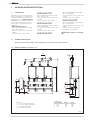 4
4
-
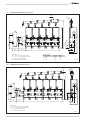 5
5
-
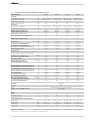 6
6
-
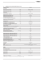 7
7
-
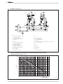 8
8
-
 9
9
-
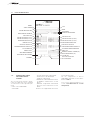 10
10
-
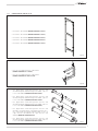 11
11
-
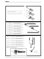 12
12
-
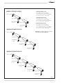 13
13
-
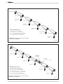 14
14
-
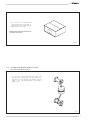 15
15
-
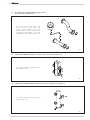 16
16
-
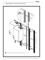 17
17
-
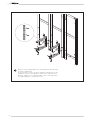 18
18
-
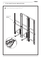 19
19
-
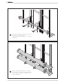 20
20
-
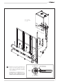 21
21
-
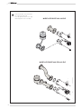 22
22
-
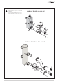 23
23
-
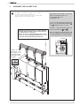 24
24
-
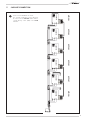 25
25
-
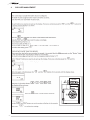 26
26
-
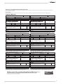 27
27
-
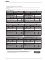 28
28
-
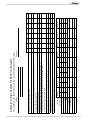 29
29
-
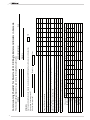 30
30
-
 31
31
-
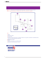 32
32
-
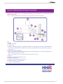 33
33
-
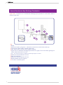 34
34
-
 35
35
-
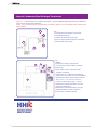 36
36
-
 37
37
-
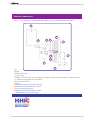 38
38
-
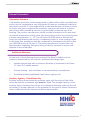 39
39
-
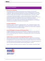 40
40
-
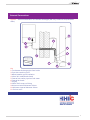 41
41
-
 42
42
-
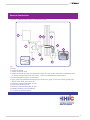 43
43
-
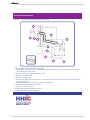 44
44
-
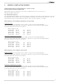 45
45
-
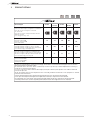 46
46
-
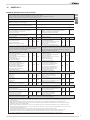 47
47
-
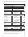 48
48
-
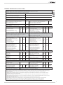 49
49
-
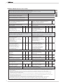 50
50
-
 51
51
-
 52
52


Sime Murelle Equipe 220 660 ErP El manual del propietario
- Tipo
- El manual del propietario
en otros idiomas
Artículos relacionados
Otros documentos
-
Kampa GA4000 Manual de usuario
-
Dometic Kampa Geyser Instrucciones de operación
-
Jacuzzi J?SP180F Instrucciones de operación
-
Hach Flo-Dar Basic User Manual
-
-
Otsein-Hoover OHTC100H Manual de usuario
-
Dimplex ESSW2 El manual del propietario
-
Candy CTR15RS/E Manual de usuario
-
Buderus 7736502326 Installation And Maintenance Instructions Manual
-
Wolf RTKF El manual del propietario