
AKO-14721 Thermostat Panel-mounted 1: 7A cos ϕ =1
(SPDT)
12V ⵑ, ±15%, 173 mAⵑ
2: 7A cos ϕ =1
(SPDT)
INSTALLATION:
Thermostat:
The thermostat must be installed in a place away from vibrations, water and corrosive gas and where the ambient
temperature is within the range in the technical specifications.
For protection level IP65, the joint between the device and the surrounding of the panel space where it is installed
must be properly made.
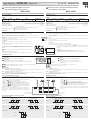
Probe:
For correct readings, the probe must be installed in a place free of thermal effects other than the temperature to be
measured or controlled.
This diagram shows how the probe must be connected:
Functions:
UP key
During programming, increases the figure being displayed.
DOWN key
During programming, lowers the figure being displayed.
Conexionado:
Conectar las regletas enchufables según esquema en etiqueta de características de los
aparatos.
Los cables para el conexionado de los contactos de los relés, deberán tener una sección
de entre 1mm
2
y 2,5 mm
2
.
La sonda y su cable correspondiente NUNCA deben instalarse en una conducción junto
con cables de potencia, control o alimentación, pudiéndose prolongar sin que produzca
desviación.
Connections:
Connect plugging terminals according to the rating plate diagram.
.
Section of connecting wires for relays contacts must be between 1mm
2
and 2,5 mm
2
.
The probe and its corresponding cable should NEVER be installed in ducting along with
mains, control or power supply wiring, probe cables can be extended and no deviation
will appear
.
www.ako.com
HOJA TÉCNICA
1472H100
Edición 06
(
01 de 02
)
E
Termostato digital hasta 600ºC, 12 V, 2 relés
para sondas Pt 100 y montaje en panel
AKO-14721
GB
Digital, 12 V, two-relay, panel mounted thermostat
for Pt 100 probes, up to 600 °C
AKO-14721
DESCRIPCIÓN GENERAL:
Termostato electrónico panelable adecuado para visualizar, controlar y regular generadores de frío o de calor.
DATOS TÉCNICOS:
Rango de temperatura:..........................................................................................................................................-50ºC a 600ºC
Entrada sonda Pt 100: ....................................................................Ref. AKO-15184, AKO-15185A, AKO-15595, AKO-15596
Precisión del controlador: ................................................................................................................................................⫾0,5ºC
Temp. ambiente de trabajo: ........................................................................................................................................5ºC a 40ºC
Temp. ambiente de almacenaje:..............................................................................................................................-30ºC a 70ºC
VERSIÓN:
MODELO FUNCIÓN ANCLAJE RELÉS ALIMENTACIÓN
AKO-14721 Termostato Panelable 1: 7A cos ϕ =1
(SPDT)
12V ⵑ, ⫾15%,173 mAⵑ
2: 7A cos ϕ =1
(SPDT)
- de montaje independiente
- de característica de funcionamiento automático acción Tipo 1.B
- para utilización en situación limpia
-soporte lógico (software) clase A
Clasificación dispositivo de control:
INSTALACIÓN:
Termostato:
El termostato debe ser instalado en un sitio protegido de las vibraciones, del agua y de los gases corrosivos,
y donde la temperatura ambiente no supere los valores reflejados en los datos técnicos.
Para que el equipo tenga un grado de protección IP65 deberá instalarse correctamente la junta entre el
aparato y el perímetro del hueco del panel donde deba montarse.
Pt100
Blanco / White
Rojo / Red
Rojo / Red
Sonda:
Para que la lectura sea correcta, la sonda se ha de instalar en un sitio sin influencias térmicas ajenas a la
temperatura que se desea medir o controlar.
La conexión de la sonda se realiza de acuerdo con el siguiente esquema:
Anclaje:
Para la fijación del aparato situar los anclajes 1 sobre las guías 2 en la posición de la
figura.
Desplazar el anclaje en el sentido de la flecha.
Presionando la pestaña 3 puede desplazarse el anclaje en sentido contrario a la flecha.
máx.
18 mm
3
2
1
61,5
70,5
28,5
HUECO PANEL
PANEL CUT-OUT
44
Fonctions:
Tecla SUBIR
En programación, sube el valor que se está visualizando.
Tecla BAJAR
En programación, baja el valor que se está visualizando.
Pulsando simultáneamente durante 10 segundos se entra en el menú de programación.
Pulsando simultáneamentese fija el nuevo valor.
LEDS indicadores:
LED 1 permanente: Indica que está activado el relé 1.
intermitente: Indica que por temperatura detectada por la sonda el relé 1 tendría que estar activado, pero no lo
está por alguna condición de programación.
LED 2 permanente: Indica que está activado el relé 2.
intermitente: Indica que por temperatura detectada por la sonda el relé 2 tendría que estar activado, pero no lo
está por alguna condición de programación.
LED PR intermitente: Fase programación punto de ajuste o parámetros.
FUNCIONES DEL FRONTAL
PRG
PR
ºC
SET
1
2
LED 2
LED 1
TECLA SUBIR
UP KEY
LED PR
TECLA BAJAR
DOWN KEY
Pulsando durante 5 segundos se entra en el menú de ajuste de las temperaturas.
Los valores de fábrica, de AJUSTE DE TEMPERATURA (Set Point) 1 y 2 por defecto son de 0°C.
AJUSTES DE LA TEMPERATURA (SET POINT):
SP1 = Punto de ajuste R1
SP2 = Punto de ajuste R2
+ Held down simultaneously for 10 seconds brings up the programming menu.
+ Held down simultaneously enters the new value.
Indicator LEDs:
LED 1 constant: Shows relay 1 is on.
flashing: Means relay 1 should be on according to the temperature detected by the probe, but is not, owing to a
programming condition.
LED 2 constant: Shows relay 2 is on.
flashing: Means relay 2 should be on according to the temperature detected by the probe, but is not, owing to a
programming condition.
LED PR flashing: Programming set point or parameters.
The default (factory) setting for SET POINTS 1 and 2 are 0ºC.
GENERAL DESCRIPTION:
Panel-mounted electronic thermostat, suitable for display, control and regulation of heat or cold generators.
TECHNICAL SPECIFICATIONS:
Temperature range: ..............................................................................................................................................-50ºC to 600ºC
Pt 100 probe entry: ........................................................................Ref. AKO-15184, AKO-15185A, AKO-15595, AKO-15596
Controller accuracy: ..........................................................................................................................................................±0,5ºC
Ambient working temperature: ..................................................................................................................................5ºC to 40ºC
Ambient storage temperature:................................................................................................................................-30ºC to 70ºC
FRONT PANELS FUNCTIONS:
VERSION:
Fastening:
To fix the unit, place the fasteners 1 over the sliders 2 as shown in the figure.
Move the fasteners in the direction of the arrow.
By pressing tab 3, the fasteners may be moved in the opposite direction to the arrow.
TEMPERATURE SET POINT:
MODEL FUNCTION MOUNTING RELAYS POWER SUPPLY
5 Seg.
5 Sec
.
AJUSTE ACTUAL
PRESENT
SETTING
INDICACIÓN
TEMPERATURA
TEMPERATURA
DISPLAY
NUEVO AJUSTE
NEW SETTING
AJUSTE ACTUAL
PRESENT
SETTING
SP1= Set Point for R1
SP2= Set Point for R2
SELECCIÓN
SELECTION
NUEVO AJUSTE
NEW SETTING
ACEPTAR EL NUEVO
ENTER NEW VALUE
VARIAR VALOR
CHANGE VALUE
VISUALIZAR
DISPLAY
MENU DE AJUSTE
SETTINGS MENU
Holding it down for 5 seconds brings up the temperature
adjustment menu.
- with independent mounting
- with characteristic of automatic operation action, Type 1.B
- to be used in clean situation
-logical medium (software) class A
Control device classification:
- Hold the key down for 5 seconds. This opens the SP1 or SP2 setting menu
(the PR led will flash).
- Press the or key to select SET POINT 1 or SET POINT 2.
- Press the + keys simultaneously to show the setting you want to change.
- Press the or keys to change the SET POINT to the figure you want.
- Press the + keys simultaneously to enter the new figure. When you do this,
the display shows the temperature again and the PR led stops flashing.
NOTE: If no key is pressed for 30 seconds during any of these steps, the controller
automatically returns to temperature display, neither of the SET POINTS being
changed.
- Pulse la tecla durante 5 segundos. Permite entrar en el menú de ajuste SP1
o SP2 y se iluminará el led PR de forma intermitente.
- Pulse las teclas ó para seleccionar el AJUSTE 1 o AJUSTE 2.
- Pulse las teclas + simultáneamente para visualizar el ajuste que desea mo-
dificar.
- Pulse las teclas ó para modificar el AJUSTE (Set Point) al valor deseado.
- Pulse las teclas + simultáneamente para fijar el nuevo valor. Al realizar esta
operación, el display volverá a la situación de indicación de temperatura y el led
PR dejará de iluminarse de forma intermitente.
NOTA: Si no se pulsa tecla alguna durante 30 segundos en cualquiera de los
pasos anteriores, el controlador volverá automáticamente a la situación de
indicación de temperatura, sin modificar los valores de los AJUSTES deseados
(Set Point).
MODOS DE FUNCIONAMIENTO Y CONTROL DE LOS RELÉS
P00=0 Actuación ON-OFF
Funcionamiento CALOR
P02=1
ON
OFF
SP2
Temp.
arranque
Temp.
paro
Temp.
arranque
Temp.
paro
SP2 + C12
C12>0
SP2SP2 - C12
C12<0
ON
OFF
SP2
Temp.
arranque
Temp.
paro
Temp.
arranque
Temp.
paro
SP2 + C12
C12>0
SP2SP2 - C12
C12<0
ON
Funcionamiento FRÍO P01=0
Funcionamiento FRÍO
P02=0
Funcionamiento CALOR P01=1
OFF
SP1
Temp.
arranque
Temp.
paro
Temp.
arranque
Temp.
paro
SP1 + C11
C11>0
SP1SP1 - C11
C11<0
ON
OFF
SP1
Temp.
arranque
Temp.
paro
Temp.
arranque
Temp.
paro
SP1 + C11
C11>0
SP1SP1 - C11
C11<0
ON
OFF
ON
OFF
SP1 - C15 SP1 + C15SP1
RELÉ 2
RELÉ 1
RELÉ 2
P00=1 Zona Neutra
RELÉ 1
RELAY CONTROL AND OPERATING MODES
P00=0 ON-OFF Switching
HEAT operation P02= 1
ON
OFF
SP2 SP2 + C12
C12>0
SP2
SP2 - C12
C12<0
ON
OFF
SP2 SP2 + C12
C12>0
SP2SP2 - C12
C12<0
ON
COLD operation P01=0
COLD operation P02=0
HEAT operation P01= 1
OFF
SP1
Temp.
ON
Temp.
OFF
Temp.
ON
Temp.
OFF
Temp.
ON
Temp.
OFF
Temp.
ON
Temp.
OFF
SP1 + C11
a C11>0
SP1SP1 - C11
C11<0
ON
OFF
SP1
Temp.
ON
Temp.
OFF
Temp.
ON
Temp.
OFF
Temp.
ON
Temp.
OFF
Temp.
ON
Temp.
OFF
SP1 + C11
C11>0
SP1SP1 - C11
C11<0
ON
OFF
ON
OFF
SP1 - C15
SP1 + C15
SP1
RELAY 2
RELAY 1
RELAY 2
P00=1 Neutral Zone
RELAY 1
+
+

MANTENIMIENTO:
Limpie la superficie del controlador con un paño suave, agua y jabón. No utilice detergentes abrasivos, gasolina, alcohol o
disolventes.
Los parámetros sólo deben ser programados o modificados por personal que
conozca el funcionamiento y las posibilidades del equipo donde se aplica.
Programación de parámetros:
Nivel 1:
- Pulse simultáneamente las teclas + durante 10 segundos. El led PR se
iluminará de forma intermitente y en el display aparecerá el primer parámetro “P00”.
- Pulse la tecla para acceder al parámetro siguiente y la tecla para retroceder
al parámetro anterior.
- Situándonos en el último parámetro EP, pulsando las teclas + simultánemente,
el controlador volverá a la situación de indicación de temperatura y el led PR dejará
de iluminarse de forma intermitente.
Nivel 2:
- Para ver el valor actual de cualquier parámetro, sitúese en el que se desea y pulse
las teclas + simultáneamente. Una vez visualizado, si quiere modificarlo pulse
las teclas ó .
- Pulse las teclas + simultáneamente para fijar el nuevo valor. Al realizar esta
operación la programación volverà al nivel 1 (parámetros).
NOTA: Si no se pulsa tecla alguna durante 30 segundos en cualquiera de los pasos
anteriores, el controlador volverá automáticamente a la situación de indicación de
temperatura, sin modificar el valor de los parámetros.
Parameters should only be programmed or chenged by personnel familiar with
the operation of the apparatus and its possibilities where applied.
Programming parameters:
Level 1:
- Hold the + keys down simultaneously for 10 seconds. The PR led will flash and
the first parameter, “P00”, will be shown on the display.
- Press the or key to change to the next parameter or previous parameter,
respectively.
- When the final parameter EP is on the display, press the + keys simultaneously,
the controller will return to the temperature display and the PR led will stop flashing.
Level 2:
- To see the current value of any parameter, find the one you want and press the + keys
simultaneously. When it is on display, you can change it with the or keys.
- Press the + keys simultaneously to set the new value. When you do this, the
programming will return to level 1 (parameters).
NOTE: If no key is pressed for 30 seconds during any of these steps, the controller
automatically returns to temperature display, none of the parameter values being
changed.
351472100 REV. 05 2005
D.L.: B-3.050-2002
Nos reservamos el derecho de suministrar materiales que pudieran diferir levemente de los descritos en nuestras hojas técnicas.
www.ako.com
HOJA TÉCNICA
1472H100
Edición 06
(
02 de 02
)
AKO Electromecànica,
S.A.L.
Av. Roquetes, 30-38 08812 S. PERE DE RIBES
(
Barcelona
)(
Spain
)
El uso del equipo no respetando las instrucciones del fabricante, puede alterar los requisitos de seguridad del mismo.
VISUALIZACIÓN
ESTADO DESCRIPCIÓN
MENSAJES DE FUNCIONAMIENTO:
AH
Intermitente con
la temperatura
Temperatura por encima del valor de los limitadores máximos del punto de ajuste de
C21 y C22.
AL
Intermitente con
la temperatura
Temperatura por debajo del valor de los limitadores mínimos del punto de ajuste de
C31 y C32.
E1
Fijo
Sonda en corto circuito, circuito abierto, >614ºC ó <-60.6ºC
EE
Fijo
Fallo de memoria.
ADVERTENCIAS:
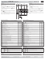
P00
Modo de funcionamiento
Selección 0 = Actuación ON-OFF
Ver modos de funcionamiento.
Posibilidad de programar puntos de ajuste independientes para cada relé.
Selección 1 = zona neutra.
Ver modos de funcionamiento.
DESCRIPCIÓN
RANGO
MIN.
0
MAX.
DEF.
1
0
P01
Funcionamiento (frío/calor) del relé 1
Selección 0 = Frío
Selección 1 = Calor
P02
Funcionamiento (frío/calor) del relé
2
Selección 0 = Frío
Selección 1 = Calor
0
1
1
P07
Resolución para la visualización de la temperatura
0=0,1 ºC entre –50,0 y +99,9 ºC, resto de escala 1 ºC
1 = 1 ºC en toda la escala.
0
1
0
P3
Volver a parámetros iniciales
1 = sí, configura todos los parámetros del equipo con los valores de la columna DEF de estas
instrucciones y sale inmediatamente de programación.
-
C0
Calibración de la sonda (offset).
Incremento / decremento de temperatura que se añade a la temperatura detectada por el
termostato para ajustar la sonda al valor real.
-20ºC
20ºC
0ºC
-650ºC +650ºC
2ºC
-650ºC
+650ºC
2ºC
C11
Diferencial R1
Incremento o decremento de temperatura por encima o por debajo de la temperatura indicada por el
PUNTO DE AJUSTE 1 (SP1) para que actúe el relé 1.
Ver funcionamiento relé 1 en actuación ON-OFF.
C12
Diferencial R2
Incremento o decremento de temperatura por encima o por debajo de la temperatura indicada por el
PUNTO DE AJUSTE 2 (SP2) para que actúe el relé 2.
Ver funcionamiento relé 2 en actuación ON-OFF.
1ºC
325ºC
2ºC
C15
Valor zona neutra
Incremento y decremento de temperatura por encima o por debajo de la temperatura programada
en el PUNTO DE AJUSTE 1 (SP1) para que actúen los relés R1 y R2.
Ver funcionamiento Zona Neutra.
xxxºC
600ºC 600ºC
C21
Limitador máximo del PUNTO DE AJUSTE (Set Point) R1
No se podrá fijar un SET POINT del relé 1 por encima de este valor, apareciendo la indicación de
alarma AH si la temperatura es superior al valor de C21 y C22.
xxxºC
600ºC 600ºC
C22
Limitador máximo del PUNTO DE AJUSTE (Set Point) R2
No se podrá fijar un SET POINT del relé 2 por encima de este valor, apareciendo la indicación de
alarma AH si la temperatura es superior al valor de C21 y C22.
-50ºC
xxxºC
-50ºC
C31
Limitador mínimo del PUNTO DE AJUSTE (Set Point) R1
No se podrá fijar un SET POINT del relé 1 por debajo de este valor, apareciendo la indicación de
alarma AL si la temperatura es inferior al valor de C31 y C32.
-50ºC
xxxºC
-50ºC
C32
Limitador mínimo del PUNTO DE AJUSTE (Set Point) R2
No se podrá fijar un SET POINT del relé 2 por debajo de este valor, apareciendo la indicación de
alarma AL si la temperatura es inferior al valor de C31 y C32.
0 min.
99 min.
0 min.
C51
Retardo accionamiento relé R1
Retardo a la conexión del relé 1 desde que la temperatura manda activarlo.
0 min.
99 min.
0 min.
C52
Retardo accionamiento relé R2
Retardo a la conexión del relé 2 desde que la temperatura manda activarlo.
0
1
0
C61
Estado de R1 con sonda averiada
0 = off
1 = on
0
1
0
C62
EP
Estado de R2 con sonda averiada
0 = off
1 = on
Salida de programación
0
1
1
1
-
VALOR
Para programar los PUNTOS DE AJUSTE (Set Point) ver AJUSTES DE LA TEMPERATURA.
Los valores de la columna DEF. vienen programados de fábrica.
DESCRIPCIÓN DE LOS PARÁMETROS:
PROGRAMACIÓN:
INDICACIÓN
TEMPERATURA
TEMPERATURE
INDICATION
NIVEL 2
VALORES
LEVEL 2 VALUES
NIVEL 1
PARÁMETROS
LEVEL 1 PARAMETERS
VISUALIZAR
VALOR
DISPLAY VALUES
VARIAR VALOR
CHANGE VALUES
ACEPTAR EL
NUEVO
ENTER NEW
VALUES
VALOR ACTUAL
CURRENT VALUE
NUEVO VALOR
NEW VALUE
10 Seg./ 10 Sec.
SALIDA PROGRAMACIÓN
PROGRAMMING EXIT
PROGRAMMING:
Using this unit without heeding the manufacturer’s instructions may change its safety requirements.
DISPLAY
STATE
DESCRIPTION
OPERATING MESSAGES:
AH
Flashing with
temperature
Temperature above the maximum limit values set in C21 and C22.
AL
Flashing with
temperature
Temperature below the minimum limit values set in C31 and C32.
E1
Steady
Probe short circuited, circuit open >614ºC or <-60.6ºC
EE
Steady
Memory failure
MAINTENANCE:
WARNINGS:
Clean the surface of the controller with a smooth cloth, soap and water. Do not use abrasive detergents, petrol, alcohol or
solvents.
P00
Operating mode
Selection 0= ON-OFF Switching.
See operating modes.
Set points can be programmed separately for each relay.
Selection 1 = neutral zone.
See operating modes.
DESCRIPTION
RANGE
MIN.
0
MAX.
VALUE
1
0
P01
Operation (cold/heat) of relay 1
Selection 0 = Cold
Selection 1 = Heat
P02
Operation (cold/heat) of relay 2
Selection 0 = Cold
Selection 1 = Heat
0
1
1
0
1
1
DEF.
For Set Point programming, see TEMPERATURE SET POINT.
The figures in the DEF column are the factory settings.
DESCRIPTION OF PARAMETERS:
P07
Resolution for temperature display.
0=0,1ºC between -50,0 and +99,9ºC rest of the range 1ºC
1= 1ºC for the complete range.
0
1
0
P3
Return to original parameters
1 sets all parameters in the device to the values in the DEF. VALUE column of this table, then
exits programming immediately.
-
C0
Probe calibration (offset)
Increases or decreases the correction to the temperature detected by the thermostat in order to
adjust the probe to real temperature.
-20ºC
20ºC
0ºC
-650ºC +650ºC
2ºC
-650ºC
+650ºC
2ºC
C11
R1 Differential
Increases or decreases the temperature from that indicated by SET POINT 1 (SP1) for R1 to be
switched on.
See relay 1 operating in ON-OFF switching mode.
C12
R2 Differential
Increase or decreases the temperature from that indicated by SET POINT 2 (SP2) for R2 to be
switched on.
See relay 2 operating in ON-OFF switching mode.
1ºC
325ºC
2ºC
C15
Neutral zone value
Increases/decreases the temperature above or below SET POINT 1 for relays R1 and R2 to
act.
See Neutral Zone operating.
xxxºC
600ºC
600ºC
C22
Maximum limit for R2 SET POINT
Relay 2’s SET POINT cannot be established above this figure, the alarm AH being produced if the
temperature is above the value of C21 and C22.
-50ºC
xxxºC
-50ºC
C31
Minimum limit for R1 SET POINT
Relay 1’s SET POINT cannot be established below this figure, the alarm AL being produced if the
temperature is less than the value of C31 and C32.
-50ºC xxxºC
-50ºC
C32
Minimum limit for R2 SET POINT
Relay 2’s SET POINT cannot be established below this figure, the alarm AL being produced if the
temperature is less than the value of C31 and C32.
0 min.
99 min.
0 min.
C51
Relay R1 Triggering Delay
Delay for R1 being triggered after the temperature commands its activation.
0 min.
99 min.
0 min.
C52
Relay R2 Triggering Delay
Delay for R2 being triggered after the temperature commands its activation.
0
1
0
C61
R1 status when the probe has failed
0=off
1=on
0
1
0
C62
EP
R2 status when the probe has failed
0=off
1=on
Exit Programming
1
-
xxxºC
600ºC
600ºC
C21
Maximum limit for R1 SET POINT
Relay 1’s SET POINT cannot be established above this figure, the alarm AH being produced if the
temperature is above the value of C21 and C22.
PARÁMETRO
PARAMETER
-
 1
1
-
 2
2


AKO Digital thermostat up to 600 °C, 12 V AKO-14721 Instrucciones de operación
- Tipo
- Instrucciones de operación
- Este manual también es adecuado para
En otros idiomas
Documentos relacionados
-
AKO 1530 Instrucciones de operación
-
-
-
-
-
-
Otros documentos
-
 AKO Electronica AKO-14721 Installation and User Instructions
-
Suzuki 1999 SY419 Manual de usuario
-
M-Audio Oxygen 61 Guía de inicio rápido
-
Danfoss 080Z5000 Guía de instalación
-
ESAB ESP-600C Manual de usuario
-
-
Optimus PA-127 Manual de usuario
-
-
-
 AKO Electronica AKO-52092 Manual de usuario

